EP3771155A1 - Gateway and method for connecting a building automation network to the internet - Google Patents
Gateway and method for connecting a building automation network to the internet Download PDFInfo
- Publication number
- EP3771155A1 EP3771155A1 EP19188279.4A EP19188279A EP3771155A1 EP 3771155 A1 EP3771155 A1 EP 3771155A1 EP 19188279 A EP19188279 A EP 19188279A EP 3771155 A1 EP3771155 A1 EP 3771155A1
- Authority
- EP
- European Patent Office
- Prior art keywords
- internet
- network
- electronic devices
- area network
- network interface
- Prior art date
- Legal status (The legal status is an assumption and is not a legal conclusion. Google has not performed a legal analysis and makes no representation as to the accuracy of the status listed.)
- Granted
Links
Images



Classifications
-
- H—ELECTRICITY
- H04—ELECTRIC COMMUNICATION TECHNIQUE
- H04L—TRANSMISSION OF DIGITAL INFORMATION, e.g. TELEGRAPHIC COMMUNICATION
- H04L12/00—Data switching networks
- H04L12/28—Data switching networks characterised by path configuration, e.g. LAN [Local Area Networks] or WAN [Wide Area Networks]
- H04L12/2803—Home automation networks
- H04L12/283—Processing of data at an internetworking point of a home automation network
- H04L12/2834—Switching of information between an external network and a home network
Definitions
- the invention relates to a gateway, a computer implemented method, a computer program and a computer-readable medium for connecting a building automation network to the internet.
- Building automation is the automatic centralized control of a building's heating, ventilation and air conditioning, lighting and other systems through a building management system or building automation system (BAS).
- BAS building automation system
- the objectives of building automation are improved occupant comfort, efficient operation of building systems, reduction in energy consumption and operating costs and improved life cycle of utilities.
- intranets which are private networks established with the technologies for local area networks (LANs) and wide area networks (WANs), also called building automation networks, are involved for connecting electronic devices designed to monitor and control the security, fire and flood safety, lighting (especially emergency lighting), heating, ventilation, and air conditioning (HVAC) etc. in a building.
- LANs local area networks
- WANs wide area networks
- HVAC heating, ventilation, and air conditioning
- cloud computing providers also provide various service models via the internet to buildings and/or the above-mentioned electronic devices to e.g. analyze the monitored conditions of the buildings to improve the building automation.
- cloud gateways are used to allow data to flow between the building automation networks and the networks of the cloud service providers.
- the building automation networks and the internet are kept physically separate. However, in some instances, they may be running on the same network.
- a conventional cloud gateway is designed to support a network configuration with either physically separating the building automation networks with the internet, or having them running on the same network. If a cloud gate way is required to function properly on both of the network configurations, additional physical and/or hardware workarounds such as double Ethernet cables and/or network switches are needed.
- the invention provides, according to a first aspect, a gateway for connecting a building automation network to the internet.
- a plurality of electronic devices are provided in the building automation network for monitoring and controlling conditions in a building, in particular security, fire and flood safety, lighting, heating, ventilation, and air conditioning (HVAC) .
- HVAC heating, ventilation, and air conditioning
- the gateway comprises a local area network interface configured to connect the gateway to the building automation network for communicating with the plurality of electronic devices, a wide area network interface configured to connect the gateway to the internet, a host network unit configured to provide a host network on which at least one local service corresponding to the monitoring and controlling of at least one of the conditions in the building runs, a container network unit configured to provide a container network for at least one remote service, in particular a cloud computing service, provided by an endpoint device or a cloud in the internet to at least one of the electronic devices, a loopback network unit configured to provide a loopback network which interconnects the host network and the container network, and a selection unit configured to select a connecting mode of the gateway from either connecting at least one of the electronic devices via the local area network interface to the internet or connecting the at least one of the electronic devices via the wide area network interface to the internet.
- the commissioning of the inventive gateway is possible for a non-IT expert, such as an installer of building products corresponding to the electronic devices for monitoring and controlling conditions in a building.
- the installer can easily select how the devices in a building automation network are connected to the Internet.
- the backend application programming interfaces APIs automatically apply the corresponding network configuration and settings, without having to involve any additional action from the installer.
- the complex network layer i.e., all the connections between the services and the networks are abstracted.
- a developer of a building product may easily assign to which network a certain local service should connect for operations.
- a developer may choose to open permitted ports required by a local service for communication with networks.
- the host network is connected to the at least one of the electronic devices via the local area network interface
- the container network is connected to the internet via the wide area network interface.
- the gateway connects to the building automation network and to the internet using separate network interfaces.
- the building automation network and the internet are physically separate.
- the host network is connected to the at least one of the electronic devices via the wide area network interface
- the container network is connected to the internet via the wide area network interface
- the gateway connects to the building automation network and to the internet using a single network interface.
- the building automation network and the internet run on the same network.
- the local service runs on the host network via the local area network interface connecting the at least one of the electronic devices with the host network. Any local service which conventionally communicates over a local area network runs inventively in the host network.
- the local service runs on the host network via the wide area network interface connecting the at least one of the electronic devices with the host network. Any local service which conventionally communicates over a local area network runs inventively in the host network.
- the outgoing data traffic of the container network is routed though the wide area network interface.
- the at least one of the electronic devices is connected to the internet via the host network, the loopback network, the container network and the wide area network interface.
- the host network unit is configured to provide the host network in which the plurality of electronic devices are communicated with each other. Thereby, the management of the local communications for local services is simplified.
- the invention further provides, according to a second aspect, a computer implemented method for connecting a building automation network to the internet.
- a plurality of electronic devices are provided in the building automation network for monitoring and controlling conditions in a building, in particular security, fire and flood safety, lighting, heating, ventilation, and air conditioning (HVAC) .
- HVAC heating, ventilation, and air conditioning
- the method comprises the steps of providing a host network on which at least one local service corresponding to the monitoring and controlling of at least one of the conditions in the building runs, providing a container network for at least one remote service, in particular a cloud computing service, provided by an endpoint device or a cloud in the internet to at least one of the electronic devices, providing a loopback network which interconnects the host network and the container network, providing a local area network interface to connect the plurality of electronic devices to the host network, providing a wide area network interface to connect the container network to the internet, and selecting from either connecting the at least one of the electronic devices via the local area network interface to the internet or connecting the at least one of the electronic devices via the wide area network interface to the internet.
- the host network is connected to the at least one of the electronic devices via the local area network interface
- the container network is connected to the internet via the wide area network interface.
- the host network is connected to the at least one of the electronic devices via the wide area network interface
- the container network is connected to the internet via the wide area network interface.
- the local service runs on the host network via the local area network interface connecting the at least one of the electronic devices with the host network.
- the local service runs on the host network via the wide area network interface connecting the at least one of the electronic devices with the host network.
- the invention further provides, according to a third aspect, a computer program comprising instructions which, when the program is executed by a computer, cause the computer to carry out the method according to the second aspect.
- a Developer of a building automation application needs to write additional code or route configurations for enabling his application to run on the host network of the inventive gateway.
- the invention further provides, according to a fourth aspect, a computer-readable medium comprising instructions which, when executed by a computer, cause the computer to carry out the method according to the second aspect.
- the embodiment of the inventive gate way 100 for connecting a building automation network 2 to the internet shown in Fig. 1a comprises a local area network interface 40 configured to connect the gateway 100 to the building automation network 2 for communicating with two electronic devices 4, 6, a wide area network interface 50 configured to connect the gateway 100 to the internet, a host network unit 10 configured to provide a host network on which at least one local service 12 corresponding to the monitoring and controlling of at least one of the conditions in the building runs, a container network unit 20 configured to provide a container network for at least one cloud computing service 14 provided by a cloud 9 in the internet to the electronic devices 4, 6, a loopback network unit configured to provide a loopback network 30 which interconnects the host network and the container network, and a selection unit configured to select a connecting mode of the gateway 100 from either connecting the electronic devices 4, 6 via the local area network interface 40 to the internet or connecting the electronic devices 4, 6 via the wide area network interface 50 to the internet.
- FIG. 1a the connecting mode in which the electronic devices 4, 6 are connected to the internet via the wide area network interface 50 is selected.
- Fig. 1b shows the network topology when the other connecting mode of the gateway 100 is selected in which the electronic devices 4, 6 are connected to the internet via the local area network interface 40.
- arrow 2a represents the connection of the host network to the building automation network 2
- arrow 8a represents the connection of the container network to the internet 8.
- the software of the gateway 100 is architected to comprise three networks that are interconnected, namely, the container network for cloud connections, the host network for all local services 12 in the building and the loopback network 30 that interconnects the container network and the host network.
- These three different networks provide flexibility in the way of connecting local services 12 (using the local area network interface 40 or the wide area network interface 50) to the internet (using the wide area network interface 50), ensuring that cybersecurity is not compromised.
- the local service 12 is a domain specific service which requires communicating with devices 4, 6 locally by means of e.g. the BACnet or Modbus protocol.
- the cloud (computing) service 14 is a service responsible to securely communicate with a cloud endpoint.
- the local area network interface 40 is a physical interface to connect to the building automation network 2 for communicating with physical devices 4, 6.
- the wide area network interface 50 is a physical interface to connect to the internet network for communicating with the internet 8.
- Fig. 2 shows a user interface 60 of another embodiment of the inventive gate way 100 for commissioning.
- a separate network mode 62 and a single network mode 64 are provided for selection.
- the gateway 100 connects to the building automation network 2, i.e. to the devices 4, 6, and to the internet 8 using separate network interfaces, i.e., the local area network interface 40 (over a local area network 22) and the wide area network interface 50 (over a wide area network 24) .
- the gateway 100 connects to the building automation network 2, i.e. to the devices 4, 6, and to the internet 8 using a single network interface, i.e., the wide area network interface 50 (over a wide area network 24) .
- the separate network mode 62 has been selected.
- a 4G or 3G dongle which is basically a small modem with the ability to connect to the 4G or 3G wireless network is provided to replace the wide area network interface 50.
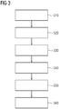
- the embodiment of the inventive computer implemented method for connecting a building automation network to the internet shown in Fig. 3 comprises six steps S10, S20, S30, S40, S50, S60.
- a host network is provided on which at least one local service corresponding to the monitoring and controlling of at least one of the conditions in the building runs.
- a container network is provided for at least one remote service, in particular a cloud computing service, provided by an endpoint device or a cloud in the internet to at least one of the electronic devices.
- a loopback network which interconnects the host network and the container network is provided.
- a local area network interface is provided to connect the plurality of electronic devices to the host network.
- a wide area network interface is provided to connect the container network to the internet.
- a connecting mode or network mode is selected from either connecting the at least one of the electronic devices via the local area network interface to the internet or connecting the at least one of the electronic devices via the wide area network interface to the internet.
- the embodiment of the inventive computer program 200 shown in Fig. 4 comprises instructions 250 which, when the program 200 is executed by a computer, cause the computer to carry out the embodiment of the inventive method shown in Fig. 3 .
- the embodiment of the inventive computer-readable medium 300 shown in Fig. 5 comprises instructions 350 which, when executed by a computer, cause the computer to carry out the embodiment of the inventive method shown in Fig. 3 .
Landscapes
- Engineering & Computer Science (AREA)
- Automation & Control Theory (AREA)
- Computing Systems (AREA)
- Computer Networks & Wireless Communication (AREA)
- Signal Processing (AREA)
- Data Exchanges In Wide-Area Networks (AREA)
- Conveying And Assembling Of Building Elements In Situ (AREA)
Abstract
Description
- The invention relates to a gateway, a computer implemented method, a computer program and a computer-readable medium for connecting a building automation network to the internet.
- Building automation is the automatic centralized control of a building's heating, ventilation and air conditioning, lighting and other systems through a building management system or building automation system (BAS). The objectives of building automation are improved occupant comfort, efficient operation of building systems, reduction in energy consumption and operating costs and improved life cycle of utilities.
- For this purpose, intranets which are private networks established with the technologies for local area networks (LANs) and wide area networks (WANs), also called building automation networks, are involved for connecting electronic devices designed to monitor and control the security, fire and flood safety, lighting (especially emergency lighting), heating, ventilation, and air conditioning (HVAC) etc. in a building.
- Besides, cloud computing providers also provide various service models via the internet to buildings and/or the above-mentioned electronic devices to e.g. analyze the monitored conditions of the buildings to improve the building automation. For connecting a building automation network to the internet for cloud services, cloud gateways are used to allow data to flow between the building automation networks and the networks of the cloud service providers.
- Conventionally, the building automation networks and the internet are kept physically separate. However, in some instances, they may be running on the same network. A conventional cloud gateway is designed to support a network configuration with either physically separating the building automation networks with the internet, or having them running on the same network. If a cloud gate way is required to function properly on both of the network configurations, additional physical and/or hardware workarounds such as double Ethernet cables and/or network switches are needed.
- This leads to a time-consuming configuration of the corresponding network setup for the cloud gateway. Furthermore, during the commissioning thereof, IT-experts are required to make sure that the whole system is installed, tested, operated, and maintained according to the operational requirements of final users.
- Accordingly, it is an object of the present invention to at least overcome the drawbacks of the conventional cloud gateways for a building automation system.
- This object is inventively achieved by the independent claims. Advantageous further developments may be taken from the dependent claims.
- The invention provides, according to a first aspect, a gateway for connecting a building automation network to the internet. A plurality of electronic devices are provided in the building automation network for monitoring and controlling conditions in a building, in particular security, fire and flood safety, lighting, heating, ventilation, and air conditioning (HVAC) . The gateway comprises a local area network interface configured to connect the gateway to the building automation network for communicating with the plurality of electronic devices, a wide area network interface configured to connect the gateway to the internet, a host network unit configured to provide a host network on which at least one local service corresponding to the monitoring and controlling of at least one of the conditions in the building runs, a container network unit configured to provide a container network for at least one remote service, in particular a cloud computing service, provided by an endpoint device or a cloud in the internet to at least one of the electronic devices, a loopback network unit configured to provide a loopback network which interconnects the host network and the container network, and a selection unit configured to select a connecting mode of the gateway from either connecting at least one of the electronic devices via the local area network interface to the internet or connecting the at least one of the electronic devices via the wide area network interface to the internet.
- It is particularly advantageous that inventively buildings presenting a variety of different network topologies are supported by the same gateway solution.
- In addition, the commissioning of the inventive gateway is possible for a non-IT expert, such as an installer of building products corresponding to the electronic devices for monitoring and controlling conditions in a building. The installer can easily select how the devices in a building automation network are connected to the Internet. Upon selection, the backend application programming interfaces (APIs) automatically apply the corresponding network configuration and settings, without having to involve any additional action from the installer.
- All configuration activities run in the backend and are not visible to the installer. The configuration is prompt, thus the time for onsite configuration being reduced compared with the state of the art, and independent of the configurations of existing devices already connected to the gateway. Once the configuration is finished, a restart of the gateway is not required.
- Furthermore, with the help of the inventive gateway, the complex network layer, i.e., all the connections between the services and the networks are abstracted. Thereby, a developer of a building product may easily assign to which network a certain local service should connect for operations.
- In order to improve the configuration of a building product, a developer may choose to open permitted ports required by a local service for communication with networks.
- It is also advantageous that when installing the inventive gateway in a building automation network, the cybersecurity against cyberattacks is ensured because the building automation network is not directly exposed to the Internet. A possible attacker from the Internet cannot reach an electronic device in the building automation network.
- In a preferable embodiment, in the connecting mode that the at least one of the electronic devices is connected to the internet via the local area network interface, the host network is connected to the at least one of the electronic devices via the local area network interface, and the container network is connected to the internet via the wide area network interface.
- In this connecting mode, the gateway connects to the building automation network and to the internet using separate network interfaces. Thus, the building automation network and the internet are physically separate.
- In a further preferable embodiment, in the connecting mode that the at least one of the electronic devices is connected to the internet via the wide area network interface, the host network is connected to the at least one of the electronic devices via the wide area network interface, and the container network is connected to the internet via the wide area network interface.
- In this connecting mode, the gateway connects to the building automation network and to the internet using a single network interface. Thus, the building automation network and the internet run on the same network.
- In a further preferable embodiment, in the connecting mode that the at least one of the electronic devices is connected to the internet via the local area network interface, the local service runs on the host network via the local area network interface connecting the at least one of the electronic devices with the host network. Any local service which conventionally communicates over a local area network runs inventively in the host network.
- In a further preferable embodiment, in the connecting mode that the at least one of the electronic devices is connected to the internet via the wide area network interface, the local service runs on the host network via the wide area network interface connecting the at least one of the electronic devices with the host network. Any local service which conventionally communicates over a local area network runs inventively in the host network.
- In a further preferable embodiment, for the remote service, the outgoing data traffic of the container network is routed though the wide area network interface. Thereby, it is ensured that all the cloud service requests are sent to the internet, but not to any of the devices in the building automation network. Any counterfeit service requests from a possible hacker in the internet would not jeopardize the security of the building automation network.
- In a further preferable embodiment, for the remote service, the at least one of the electronic devices is connected to the internet via the host network, the loopback network, the container network and the wide area network interface. Thereby, it is possible to simplify the management of all the devices in the building automation network for connecting to the internet.
- In a further preferable embodiment, the host network unit is configured to provide the host network in which the plurality of electronic devices are communicated with each other. Thereby, the management of the local communications for local services is simplified.
- The invention further provides, according to a second aspect, a computer implemented method for connecting a building automation network to the internet. A plurality of electronic devices are provided in the building automation network for monitoring and controlling conditions in a building, in particular security, fire and flood safety, lighting, heating, ventilation, and air conditioning (HVAC) . The method comprises the steps of providing a host network on which at least one local service corresponding to the monitoring and controlling of at least one of the conditions in the building runs, providing a container network for at least one remote service, in particular a cloud computing service, provided by an endpoint device or a cloud in the internet to at least one of the electronic devices, providing a loopback network which interconnects the host network and the container network, providing a local area network interface to connect the plurality of electronic devices to the host network, providing a wide area network interface to connect the container network to the internet, and selecting from either connecting the at least one of the electronic devices via the local area network interface to the internet or connecting the at least one of the electronic devices via the wide area network interface to the internet.
- In a preferable embodiment of the computer implemented method, if connecting the at least one of the electronic devices via the local area network interface to the internet is selected, the host network is connected to the at least one of the electronic devices via the local area network interface, and the container network is connected to the internet via the wide area network interface.
- In a further preferable embodiment of the computer implemented method, if connecting the at least one of the electronic devices via the wide area network interface to the internet is selected, the host network is connected to the at least one of the electronic devices via the wide area network interface, and the container network is connected to the internet via the wide area network interface.
- In a further preferable embodiment of the computer implemented method, if connecting the at least one of the electronic devices via the local area network interface to the internet is selected, the local service runs on the host network via the local area network interface connecting the at least one of the electronic devices with the host network.
- In a further preferable embodiment of the computer implemented method, if connecting the at least one of the electronic devices via the wide area network interface to the internet is selected, the local service runs on the host network via the wide area network interface connecting the at least one of the electronic devices with the host network.
- The invention further provides, according to a third aspect, a computer program comprising instructions which, when the program is executed by a computer, cause the computer to carry out the method according to the second aspect.
- A Developer of a building automation application needs to write additional code or route configurations for enabling his application to run on the host network of the inventive gateway.
- The invention further provides, according to a fourth aspect, a computer-readable medium comprising instructions which, when executed by a computer, cause the computer to carry out the method according to the second aspect.
- Further advantageous details and features may be taken from the following description of several exemplary embodiments of the invention in conjunction with the drawings, in which:
-
Fig. 1a shows schematically an embodiment of the inventive gate way connected to a building automation network and a cloud, the gate way being in one of the connecting modes; -
Fig. 1b shows schematically the embodiment of the inventive gate way shown inFig. 1a , the gate way being in the other connecting mode; -
Fig. 2 shows schematically a user interface of another embodiment of the inventive gate way; -
Fig. 3 shows a block diagram of an embodiment of the inventive computer implemented method for connecting a building automation network to the internet; -
Fig. 4 shows a block diagram of an embodiment of the inventive computer program; and -
Fig. 5 shows a block diagram of an embodiment of the inventive computer-readable medium. - The embodiment of the
inventive gate way 100 for connecting abuilding automation network 2 to the internet shown inFig. 1a comprises a localarea network interface 40 configured to connect thegateway 100 to thebuilding automation network 2 for communicating with twoelectronic devices area network interface 50 configured to connect thegateway 100 to the internet, ahost network unit 10 configured to provide a host network on which at least onelocal service 12 corresponding to the monitoring and controlling of at least one of the conditions in the building runs, acontainer network unit 20 configured to provide a container network for at least onecloud computing service 14 provided by acloud 9 in the internet to theelectronic devices loopback network 30 which interconnects the host network and the container network, and a selection unit configured to select a connecting mode of thegateway 100 from either connecting theelectronic devices area network interface 40 to the internet or connecting theelectronic devices area network interface 50 to the internet. - As shown in
Fig. 1a , the connecting mode in which theelectronic devices area network interface 50 is selected.Fig. 1b shows the network topology when the other connecting mode of thegateway 100 is selected in which theelectronic devices area network interface 40. In both of the figures,arrow 2a represents the connection of the host network to thebuilding automation network 2, andarrow 8a represents the connection of the container network to theinternet 8. - The software of the
gateway 100 is architected to comprise three networks that are interconnected, namely, the container network for cloud connections, the host network for alllocal services 12 in the building and theloopback network 30 that interconnects the container network and the host network. - These three different networks provide flexibility in the way of connecting local services 12 (using the local
area network interface 40 or the wide area network interface 50) to the internet (using the wide area network interface 50), ensuring that cybersecurity is not compromised. - The
local service 12 is a domain specific service which requires communicating withdevices service 14 is a service responsible to securely communicate with a cloud endpoint. The localarea network interface 40 is a physical interface to connect to thebuilding automation network 2 for communicating withphysical devices area network interface 50 is a physical interface to connect to the internet network for communicating with theinternet 8. -
Fig. 2 shows auser interface 60 of another embodiment of theinventive gate way 100 for commissioning. In theuser interface 60, aseparate network mode 62 and asingle network mode 64 are provided for selection. In theseparate network mode 62, thegateway 100 connects to thebuilding automation network 2, i.e. to thedevices internet 8 using separate network interfaces, i.e., the local area network interface 40 (over a local area network 22) and the wide area network interface 50 (over a wide area network 24) . In thesingle network mode 64, thegateway 100 connects to thebuilding automation network 2, i.e. to thedevices internet 8 using a single network interface, i.e., the wide area network interface 50 (over a wide area network 24) . In theuser interface 60 shown inFig. 2 , theseparate network mode 62 has been selected. - In an embodiment of the gateway not shown, in the
separate network mode 62, a 4G or 3G dongle which is basically a small modem with the ability to connect to the 4G or 3G wireless network is provided to replace the widearea network interface 50. - The embodiment of the inventive computer implemented method for connecting a building automation network to the internet shown in
Fig. 3 comprises six steps S10, S20, S30, S40, S50, S60. - In step S10, a host network is provided on which at least one local service corresponding to the monitoring and controlling of at least one of the conditions in the building runs. In step S20, a container network is provided for at least one remote service, in particular a cloud computing service, provided by an endpoint device or a cloud in the internet to at least one of the electronic devices. In step S30, a loopback network which interconnects the host network and the container network is provided. In step S40, a local area network interface is provided to connect the plurality of electronic devices to the host network. In step S50, a wide area network interface is provided to connect the container network to the internet. In step S60, a connecting mode or network mode is selected from either connecting the at least one of the electronic devices via the local area network interface to the internet or connecting the at least one of the electronic devices via the wide area network interface to the internet.
- The embodiment of the
inventive computer program 200 shown inFig. 4 comprisesinstructions 250 which, when theprogram 200 is executed by a computer, cause the computer to carry out the embodiment of the inventive method shown inFig. 3 . - The embodiment of the inventive computer-
readable medium 300 shown inFig. 5 comprisesinstructions 350 which, when executed by a computer, cause the computer to carry out the embodiment of the inventive method shown inFig. 3 . - The invention is described and illustrated in detail by the preferable embodiments mentioned above. However, the invention is not limited by the disclosed examples, and other variations can be derived therefrom while still being inside the protection scope of the invention. For instance, for each building, more than one gate way may be employed, each for connecting a building automation network to the internet.
Claims (15)
- A gateway (100) for connecting a building automation network (2) to the internet (8), wherein a plurality of electronic devices (4, 6) are provided in the building automation network (2) for monitoring and controlling conditions in a building, in particular security, fire and flood safety, lighting, heating, ventilation, and air conditioning (HVAC), the gateway (100) comprising
a local area network interface (40) configured to connect the gateway (100) to the building automation network (2) for communicating with the plurality of electronic devices (4, 6), a wide area network interface (50) configured to connect the gateway (100) to the internet (8),
a host network unit (10) configured to provide a host network on which at least one local service (12) corresponding to the monitoring and controlling of at least one of the conditions in the building runs,
a container network unit (20) configured to provide a container network for at least one remote service (14), in particular a cloud computing service (14), provided by an endpoint device or a cloud (9) in the internet (8) to at least one of the electronic devices (4, 6),
a loopback network unit configured to provide a loopback network (30) which interconnects the host network and the container network, and
a selection unit configured to select a connecting mode of the gateway (100) from either connecting at least one of the electronic devices (4, 6) via the local area network interface (40) to the internet (8) or connecting the at least one of the electronic devices (4, 6) via the wide area network interface (50) to the internet (8). - The gateway (100) according to claim 1, wherein in the connecting mode that the at least one of the electronic devices (4, 6) is connected to the internet (8) via the local area network interface (40), the host network is connected to the at least one of the electronic devices (4, 6) via the local area network interface (40), and the container network is connected to the internet (8) via the wide area network interface (50).
- The gateway (100) according to claim 1, wherein in the connecting mode that the at least one of the electronic devices (4, 6) is connected to the internet (8) via the wide area network interface (50), the host network is connected to the at least one of the electronic devices (4, 6) via the wide area network interface (50), and the container network is connected to the internet (8) via the wide area network interface (50).
- The gateway (100) according to claim 1 or 2, wherein in the connecting mode that the at least one of the electronic devices (4, 6) is connected to the internet (8) via the local area network interface (40), the local service (12) runs on the host network via the local area network interface (40) connecting the at least one of the electronic devices (4, 6) with the host network.
- The gateway (100) according to claim 1 or 3, wherein in the connecting mode that the at least one of the electronic devices (4, 6) is connected to the internet (8) via the wide area network interface (50), the local service (12) runs on the host network via the wide area network interface (50) connecting the at least one of the electronic devices (4, 6) with the host network.
- The gateway (100) according to any of the preceding claims, wherein for the remote service (14), the outgoing data traffic of the container network is routed though the wide area network interface (50).
- The gateway (100) according to any of the preceding claims, wherein for the remote service (14), the at least one of the electronic devices (4, 6) is connected to the internet (8) via the host network, the loopback network (30), the container network and the wide area network interface (50).
- The gateway (100) according to any of the preceding claims, wherein the host network unit (10) is configured to provide the host network in which the plurality of electronic devices (4, 6) are communicated with each other.
- A computer implemented method for connecting a building automation network (2) to the internet (8), wherein a plurality of electronic devices (4, 6) are provided in the building automation network (2) for monitoring and controlling conditions in a building, in particular security, fire and flood safety, lighting, heating, ventilation, and air conditioning (HVAC), the method comprising the steps of:providing (S10) a host network on which at least one local service (12) corresponding to the monitoring and controlling of at least one of the conditions in the building runs,providing (S20) a container network for at least one remote service (14), in particular a cloud computing service (14),provided by an endpoint device or a cloud (9) in the internet (8) to at least one of the electronic devices (4, 6),providing (S30) a loopback network (30) which interconnects the host network and the container network,providing (S40) a local area network interface (40) to connect the plurality of electronic devices (4, 6) to the host network,providing (S50) a wide area network interface (50) to connect the container network to the internet (8), andselecting (S60) from either connecting the at least one of the electronic devices (4, 6) via the local area network interface (40) to the internet (8) or connecting the at least one of the electronic devices (4, 6) via the wide area network interface (50) to the internet (8).
- The computer implemented method according to claim 9, wherein if connecting the at least one of the electronic devices (4, 6) via the local area network interface (40) to the internet (8) is selected, the host network is connected to the at least one of the electronic devices (4, 6) via the local area network interface (40), and the container network is connected to the internet (8) via the wide area network interface (50).
- The computer implemented method according to claim 9, wherein if connecting the at least one of the electronic devices (4, 6) via the wide area network interface (50) to the internet (8) is selected, the host network is connected to the at least one of the electronic devices (4, 6) via the wide area network interface (50), and the container network is connected to the internet (8) via the wide area network interface (50).
- The computer implemented method according to claim 9 or 10, wherein if connecting the at least one of the electronic devices (4, 6) via the local area network interface (40) to the internet (8) is selected, the local service (12) runs on the host network via the local area network interface (40) connecting the at least one of the electronic devices (4, 6) with the host network.
- The computer implemented method according to claim 9 or 11, wherein if connecting the at least one of the electronic devices (4, 6) via the wide area network interface (50) to the internet (8) is selected, the local service (12) runs on the host network via the wide area network interface (50) connecting the at least one of the electronic devices (4, 6) with the host network.
- A computer program (200) comprising instructions (250) which, when the program is executed by a computer, cause the computer to carry out the method of any one of claims 9 to 13.
- A computer-readable medium (300) comprising instructions (350) which, when executed by a computer, cause the computer to carry out the method of any one of claims 9 to 13.
Priority Applications (2)
| Application Number | Priority Date | Filing Date | Title |
|---|---|---|---|
| FIEP19188279.4T FI3771155T3 (en) | 2019-07-25 | 2019-07-25 | Gateway and method for connecting a building automation network to the internet |
| EP19188279.4A EP3771155B1 (en) | 2019-07-25 | 2019-07-25 | Gateway and method for connecting a building automation network to the internet |
Applications Claiming Priority (1)
| Application Number | Priority Date | Filing Date | Title |
|---|---|---|---|
| EP19188279.4A EP3771155B1 (en) | 2019-07-25 | 2019-07-25 | Gateway and method for connecting a building automation network to the internet |
Publications (2)
| Publication Number | Publication Date |
|---|---|
| EP3771155A1 true EP3771155A1 (en) | 2021-01-27 |
| EP3771155B1 EP3771155B1 (en) | 2024-03-06 |
Family
ID=67438849
Family Applications (1)
| Application Number | Title | Priority Date | Filing Date |
|---|---|---|---|
| EP19188279.4A Active EP3771155B1 (en) | 2019-07-25 | 2019-07-25 | Gateway and method for connecting a building automation network to the internet |
Country Status (2)
| Country | Link |
|---|---|
| EP (1) | EP3771155B1 (en) |
| FI (1) | FI3771155T3 (en) |
Cited By (1)
| Publication number | Priority date | Publication date | Assignee | Title |
|---|---|---|---|---|
| US12467975B2 (en) | 2023-03-07 | 2025-11-11 | Honeywell International Inc. | Generating a lighting system analysis |
Citations (3)
| Publication number | Priority date | Publication date | Assignee | Title |
|---|---|---|---|---|
| US20090067441A1 (en) * | 2007-09-11 | 2009-03-12 | Amir Ansari | Multi-interface wireless adapter and network bridge |
| US20110277001A1 (en) * | 2010-05-06 | 2011-11-10 | Ikanos Communications, Inc. | Gateway Device |
| US20180316513A1 (en) * | 2017-04-27 | 2018-11-01 | Johnson Controls Technology Company | Temporary service and equipment installation network for a building |
-
2019
- 2019-07-25 EP EP19188279.4A patent/EP3771155B1/en active Active
- 2019-07-25 FI FIEP19188279.4T patent/FI3771155T3/en active
Patent Citations (3)
| Publication number | Priority date | Publication date | Assignee | Title |
|---|---|---|---|---|
| US20090067441A1 (en) * | 2007-09-11 | 2009-03-12 | Amir Ansari | Multi-interface wireless adapter and network bridge |
| US20110277001A1 (en) * | 2010-05-06 | 2011-11-10 | Ikanos Communications, Inc. | Gateway Device |
| US20180316513A1 (en) * | 2017-04-27 | 2018-11-01 | Johnson Controls Technology Company | Temporary service and equipment installation network for a building |
Cited By (1)
| Publication number | Priority date | Publication date | Assignee | Title |
|---|---|---|---|---|
| US12467975B2 (en) | 2023-03-07 | 2025-11-11 | Honeywell International Inc. | Generating a lighting system analysis |
Also Published As
| Publication number | Publication date |
|---|---|
| FI3771155T3 (en) | 2024-05-16 |
| EP3771155B1 (en) | 2024-03-06 |
Similar Documents
| Publication | Publication Date | Title |
|---|---|---|
| EP4292248B1 (en) | Cloud-based automation system, zone control, building gateway and method for increasing the energy efficiency of buildings | |
| EP3681110B1 (en) | A region interconnect control using vrf tables across heterogeneous networks | |
| RU2651149C2 (en) | Sdn-controller, data processing center system and the routed connection method | |
| US20100280636A1 (en) | Building automation system controller including network management features | |
| US20120131579A1 (en) | Method and system for deploying at least one virtual network on the fly and on demand | |
| US11218370B2 (en) | Method for applying a patch to a virtualized network function to be updated | |
| CN108183935B (en) | Method for providing network communication between IP devices via internet | |
| JP2010178089A (en) | Remote management system, remote management apparatus and connection device | |
| US20180083917A1 (en) | Topology Based Internet Protocol (IP) Addressing | |
| JP2016503978A (en) | Method for automatically deploying network device configurations | |
| RU2678486C1 (en) | Method of configuring modular control device of industrial automation system and modular control device | |
| EP3771155B1 (en) | Gateway and method for connecting a building automation network to the internet | |
| CN112671914B (en) | IOT (Internet of things) equipment communication method and system based on actor model | |
| CN105308909A (en) | Device in a building system and building technology system | |
| US20180167229A1 (en) | Method, Communication Web Service, And Server For Providing Network Communication Between BACNET Devices | |
| US12001179B2 (en) | Control subsystem having an integration framework | |
| US9838218B2 (en) | Method for providing overlay network interworking with underlay network and system performing same | |
| JP5445626B2 (en) | Network management system | |
| KR101315219B1 (en) | Facilities controller, and system and method for monitoring and controllging facilities having the same | |
| US11165595B2 (en) | Network and switch providing controllable power through outlets and communication ports | |
| KR20150116509A (en) | Method and appratus for collecting and analyzing traffic data on cloud computing system | |
| JP2007215187A (en) | Data transmission method, communication apparatus and coupling module via data network | |
| KR20240129352A (en) | Sdn controller, sdn network system and method for implementing ztp(zero touch provisioning) based on l3 routing protocol | |
| US12294468B2 (en) | Building controller with managed multiport switch | |
| US11463326B2 (en) | Lightweight ring manager with distributed policies |
Legal Events
| Date | Code | Title | Description |
|---|---|---|---|
| PUAI | Public reference made under article 153(3) epc to a published international application that has entered the european phase |
Free format text: ORIGINAL CODE: 0009012 |
|
| STAA | Information on the status of an ep patent application or granted ep patent |
Free format text: STATUS: THE APPLICATION HAS BEEN PUBLISHED |
|
| AK | Designated contracting states |
Kind code of ref document: A1 Designated state(s): AL AT BE BG CH CY CZ DE DK EE ES FI FR GB GR HR HU IE IS IT LI LT LU LV MC MK MT NL NO PL PT RO RS SE SI SK SM TR |
|
| AX | Request for extension of the european patent |
Extension state: BA ME |
|
| STAA | Information on the status of an ep patent application or granted ep patent |
Free format text: STATUS: REQUEST FOR EXAMINATION WAS MADE |
|
| STAA | Information on the status of an ep patent application or granted ep patent |
Free format text: STATUS: EXAMINATION IS IN PROGRESS |
|
| 17P | Request for examination filed |
Effective date: 20210719 |
|
| RBV | Designated contracting states (corrected) |
Designated state(s): AL AT BE BG CH CY CZ DE DK EE ES FI FR GB GR HR HU IE IS IT LI LT LU LV MC MK MT NL NO PL PT RO RS SE SI SK SM TR |
|
| 17Q | First examination report despatched |
Effective date: 20210812 |
|
| GRAP | Despatch of communication of intention to grant a patent |
Free format text: ORIGINAL CODE: EPIDOSNIGR1 |
|
| STAA | Information on the status of an ep patent application or granted ep patent |
Free format text: STATUS: GRANT OF PATENT IS INTENDED |
|
| INTG | Intention to grant announced |
Effective date: 20231220 |
|
| GRAS | Grant fee paid |
Free format text: ORIGINAL CODE: EPIDOSNIGR3 |
|
| GRAA | (expected) grant |
Free format text: ORIGINAL CODE: 0009210 |
|
| STAA | Information on the status of an ep patent application or granted ep patent |
Free format text: STATUS: THE PATENT HAS BEEN GRANTED |
|
| AK | Designated contracting states |
Kind code of ref document: B1 Designated state(s): AL AT BE BG CH CY CZ DE DK EE ES FI FR GB GR HR HU IE IS IT LI LT LU LV MC MK MT NL NO PL PT RO RS SE SI SK SM TR |
|
| REG | Reference to a national code |
Ref country code: CH Ref legal event code: EP |
|
| REG | Reference to a national code |
Ref country code: IE Ref legal event code: FG4D |
|
| REG | Reference to a national code |
Ref country code: DE Ref legal event code: R096 Ref document number: 602019047644 Country of ref document: DE |
|
| REG | Reference to a national code |
Ref country code: FI Ref legal event code: FGE |
|
| REG | Reference to a national code |
Ref country code: SE Ref legal event code: TRGR |
|
| REG | Reference to a national code |
Ref country code: LT Ref legal event code: MG9D |
|
| REG | Reference to a national code |
Ref country code: NL Ref legal event code: FP |
|
| PG25 | Lapsed in a contracting state [announced via postgrant information from national office to epo] |
Ref country code: LT Free format text: LAPSE BECAUSE OF FAILURE TO SUBMIT A TRANSLATION OF THE DESCRIPTION OR TO PAY THE FEE WITHIN THE PRESCRIBED TIME-LIMIT Effective date: 20240306 |
|
| PG25 | Lapsed in a contracting state [announced via postgrant information from national office to epo] |
Ref country code: GR Free format text: LAPSE BECAUSE OF FAILURE TO SUBMIT A TRANSLATION OF THE DESCRIPTION OR TO PAY THE FEE WITHIN THE PRESCRIBED TIME-LIMIT Effective date: 20240607 |
|
| PG25 | Lapsed in a contracting state [announced via postgrant information from national office to epo] |
Ref country code: RS Free format text: LAPSE BECAUSE OF FAILURE TO SUBMIT A TRANSLATION OF THE DESCRIPTION OR TO PAY THE FEE WITHIN THE PRESCRIBED TIME-LIMIT Effective date: 20240606 Ref country code: HR Free format text: LAPSE BECAUSE OF FAILURE TO SUBMIT A TRANSLATION OF THE DESCRIPTION OR TO PAY THE FEE WITHIN THE PRESCRIBED TIME-LIMIT Effective date: 20240306 |
|
| PG25 | Lapsed in a contracting state [announced via postgrant information from national office to epo] |
Ref country code: ES Free format text: LAPSE BECAUSE OF FAILURE TO SUBMIT A TRANSLATION OF THE DESCRIPTION OR TO PAY THE FEE WITHIN THE PRESCRIBED TIME-LIMIT Effective date: 20240306 |
|
| PG25 | Lapsed in a contracting state [announced via postgrant information from national office to epo] |
Ref country code: RS Free format text: LAPSE BECAUSE OF FAILURE TO SUBMIT A TRANSLATION OF THE DESCRIPTION OR TO PAY THE FEE WITHIN THE PRESCRIBED TIME-LIMIT Effective date: 20240606 Ref country code: NO Free format text: LAPSE BECAUSE OF FAILURE TO SUBMIT A TRANSLATION OF THE DESCRIPTION OR TO PAY THE FEE WITHIN THE PRESCRIBED TIME-LIMIT Effective date: 20240606 Ref country code: LT Free format text: LAPSE BECAUSE OF FAILURE TO SUBMIT A TRANSLATION OF THE DESCRIPTION OR TO PAY THE FEE WITHIN THE PRESCRIBED TIME-LIMIT Effective date: 20240306 Ref country code: HR Free format text: LAPSE BECAUSE OF FAILURE TO SUBMIT A TRANSLATION OF THE DESCRIPTION OR TO PAY THE FEE WITHIN THE PRESCRIBED TIME-LIMIT Effective date: 20240306 Ref country code: GR Free format text: LAPSE BECAUSE OF FAILURE TO SUBMIT A TRANSLATION OF THE DESCRIPTION OR TO PAY THE FEE WITHIN THE PRESCRIBED TIME-LIMIT Effective date: 20240607 Ref country code: ES Free format text: LAPSE BECAUSE OF FAILURE TO SUBMIT A TRANSLATION OF THE DESCRIPTION OR TO PAY THE FEE WITHIN THE PRESCRIBED TIME-LIMIT Effective date: 20240306 Ref country code: BG Free format text: LAPSE BECAUSE OF FAILURE TO SUBMIT A TRANSLATION OF THE DESCRIPTION OR TO PAY THE FEE WITHIN THE PRESCRIBED TIME-LIMIT Effective date: 20240306 |
|
| PG25 | Lapsed in a contracting state [announced via postgrant information from national office to epo] |
Ref country code: LV Free format text: LAPSE BECAUSE OF FAILURE TO SUBMIT A TRANSLATION OF THE DESCRIPTION OR TO PAY THE FEE WITHIN THE PRESCRIBED TIME-LIMIT Effective date: 20240306 |
|
| PG25 | Lapsed in a contracting state [announced via postgrant information from national office to epo] |
Ref country code: IS Free format text: LAPSE BECAUSE OF FAILURE TO SUBMIT A TRANSLATION OF THE DESCRIPTION OR TO PAY THE FEE WITHIN THE PRESCRIBED TIME-LIMIT Effective date: 20240706 |
|
| PG25 | Lapsed in a contracting state [announced via postgrant information from national office to epo] |
Ref country code: PT Free format text: LAPSE BECAUSE OF FAILURE TO SUBMIT A TRANSLATION OF THE DESCRIPTION OR TO PAY THE FEE WITHIN THE PRESCRIBED TIME-LIMIT Effective date: 20240708 Ref country code: SM Free format text: LAPSE BECAUSE OF FAILURE TO SUBMIT A TRANSLATION OF THE DESCRIPTION OR TO PAY THE FEE WITHIN THE PRESCRIBED TIME-LIMIT Effective date: 20240306 |
|
| PG25 | Lapsed in a contracting state [announced via postgrant information from national office to epo] |
Ref country code: EE Free format text: LAPSE BECAUSE OF FAILURE TO SUBMIT A TRANSLATION OF THE DESCRIPTION OR TO PAY THE FEE WITHIN THE PRESCRIBED TIME-LIMIT Effective date: 20240306 Ref country code: CZ Free format text: LAPSE BECAUSE OF FAILURE TO SUBMIT A TRANSLATION OF THE DESCRIPTION OR TO PAY THE FEE WITHIN THE PRESCRIBED TIME-LIMIT Effective date: 20240306 |
|
| PG25 | Lapsed in a contracting state [announced via postgrant information from national office to epo] |
Ref country code: PL Free format text: LAPSE BECAUSE OF FAILURE TO SUBMIT A TRANSLATION OF THE DESCRIPTION OR TO PAY THE FEE WITHIN THE PRESCRIBED TIME-LIMIT Effective date: 20240306 |
|
| PG25 | Lapsed in a contracting state [announced via postgrant information from national office to epo] |
Ref country code: SK Free format text: LAPSE BECAUSE OF FAILURE TO SUBMIT A TRANSLATION OF THE DESCRIPTION OR TO PAY THE FEE WITHIN THE PRESCRIBED TIME-LIMIT Effective date: 20240306 |
|
| PG25 | Lapsed in a contracting state [announced via postgrant information from national office to epo] |
Ref country code: SM Free format text: LAPSE BECAUSE OF FAILURE TO SUBMIT A TRANSLATION OF THE DESCRIPTION OR TO PAY THE FEE WITHIN THE PRESCRIBED TIME-LIMIT Effective date: 20240306 Ref country code: SK Free format text: LAPSE BECAUSE OF FAILURE TO SUBMIT A TRANSLATION OF THE DESCRIPTION OR TO PAY THE FEE WITHIN THE PRESCRIBED TIME-LIMIT Effective date: 20240306 Ref country code: RO Free format text: LAPSE BECAUSE OF FAILURE TO SUBMIT A TRANSLATION OF THE DESCRIPTION OR TO PAY THE FEE WITHIN THE PRESCRIBED TIME-LIMIT Effective date: 20240306 Ref country code: PT Free format text: LAPSE BECAUSE OF FAILURE TO SUBMIT A TRANSLATION OF THE DESCRIPTION OR TO PAY THE FEE WITHIN THE PRESCRIBED TIME-LIMIT Effective date: 20240708 Ref country code: PL Free format text: LAPSE BECAUSE OF FAILURE TO SUBMIT A TRANSLATION OF THE DESCRIPTION OR TO PAY THE FEE WITHIN THE PRESCRIBED TIME-LIMIT Effective date: 20240306 Ref country code: IS Free format text: LAPSE BECAUSE OF FAILURE TO SUBMIT A TRANSLATION OF THE DESCRIPTION OR TO PAY THE FEE WITHIN THE PRESCRIBED TIME-LIMIT Effective date: 20240706 Ref country code: EE Free format text: LAPSE BECAUSE OF FAILURE TO SUBMIT A TRANSLATION OF THE DESCRIPTION OR TO PAY THE FEE WITHIN THE PRESCRIBED TIME-LIMIT Effective date: 20240306 Ref country code: CZ Free format text: LAPSE BECAUSE OF FAILURE TO SUBMIT A TRANSLATION OF THE DESCRIPTION OR TO PAY THE FEE WITHIN THE PRESCRIBED TIME-LIMIT Effective date: 20240306 |
|
| REG | Reference to a national code |
Ref country code: DE Ref legal event code: R097 Ref document number: 602019047644 Country of ref document: DE |
|
| PLBE | No opposition filed within time limit |
Free format text: ORIGINAL CODE: 0009261 |
|
| STAA | Information on the status of an ep patent application or granted ep patent |
Free format text: STATUS: NO OPPOSITION FILED WITHIN TIME LIMIT |
|
| PG25 | Lapsed in a contracting state [announced via postgrant information from national office to epo] |
Ref country code: DK Free format text: LAPSE BECAUSE OF FAILURE TO SUBMIT A TRANSLATION OF THE DESCRIPTION OR TO PAY THE FEE WITHIN THE PRESCRIBED TIME-LIMIT Effective date: 20240306 |
|
| PG25 | Lapsed in a contracting state [announced via postgrant information from national office to epo] |
Ref country code: DK Free format text: LAPSE BECAUSE OF FAILURE TO SUBMIT A TRANSLATION OF THE DESCRIPTION OR TO PAY THE FEE WITHIN THE PRESCRIBED TIME-LIMIT Effective date: 20240306 |
|
| PG25 | Lapsed in a contracting state [announced via postgrant information from national office to epo] |
Ref country code: MC Free format text: LAPSE BECAUSE OF FAILURE TO SUBMIT A TRANSLATION OF THE DESCRIPTION OR TO PAY THE FEE WITHIN THE PRESCRIBED TIME-LIMIT Effective date: 20240306 |
|
| 26N | No opposition filed |
Effective date: 20241209 |
|
| PG25 | Lapsed in a contracting state [announced via postgrant information from national office to epo] |
Ref country code: LU Free format text: LAPSE BECAUSE OF NON-PAYMENT OF DUE FEES Effective date: 20240725 |
|
| PG25 | Lapsed in a contracting state [announced via postgrant information from national office to epo] |
Ref country code: LU Free format text: LAPSE BECAUSE OF NON-PAYMENT OF DUE FEES Effective date: 20240725 |
|
| PG25 | Lapsed in a contracting state [announced via postgrant information from national office to epo] |
Ref country code: SI Free format text: LAPSE BECAUSE OF FAILURE TO SUBMIT A TRANSLATION OF THE DESCRIPTION OR TO PAY THE FEE WITHIN THE PRESCRIBED TIME-LIMIT Effective date: 20240306 Ref country code: BE Free format text: LAPSE BECAUSE OF NON-PAYMENT OF DUE FEES Effective date: 20240731 |
|
| REG | Reference to a national code |
Ref country code: BE Ref legal event code: MM Effective date: 20240731 |
|
| PG25 | Lapsed in a contracting state [announced via postgrant information from national office to epo] |
Ref country code: IE Free format text: LAPSE BECAUSE OF NON-PAYMENT OF DUE FEES Effective date: 20240725 |
|
| PGFP | Annual fee paid to national office [announced via postgrant information from national office to epo] |
Ref country code: NL Payment date: 20250709 Year of fee payment: 7 |
|
| REG | Reference to a national code |
Ref country code: CH Ref legal event code: U11 Free format text: ST27 STATUS EVENT CODE: U-0-0-U10-U11 (AS PROVIDED BY THE NATIONAL OFFICE) Effective date: 20251006 |
|
| PGFP | Annual fee paid to national office [announced via postgrant information from national office to epo] |
Ref country code: FI Payment date: 20250725 Year of fee payment: 7 |
|
| PGFP | Annual fee paid to national office [announced via postgrant information from national office to epo] |
Ref country code: DE Payment date: 20250919 Year of fee payment: 7 |
|
| PGFP | Annual fee paid to national office [announced via postgrant information from national office to epo] |
Ref country code: IT Payment date: 20250718 Year of fee payment: 7 |
|
| PGFP | Annual fee paid to national office [announced via postgrant information from national office to epo] |
Ref country code: GB Payment date: 20250811 Year of fee payment: 7 |
|
| PGFP | Annual fee paid to national office [announced via postgrant information from national office to epo] |
Ref country code: AT Payment date: 20250606 Year of fee payment: 7 Ref country code: FR Payment date: 20250716 Year of fee payment: 7 |
|
| PGFP | Annual fee paid to national office [announced via postgrant information from national office to epo] |
Ref country code: SE Payment date: 20250707 Year of fee payment: 7 |
|
| PGFP | Annual fee paid to national office [announced via postgrant information from national office to epo] |
Ref country code: CH Payment date: 20251006 Year of fee payment: 7 |
|
| PG25 | Lapsed in a contracting state [announced via postgrant information from national office to epo] |
Ref country code: CY Free format text: LAPSE BECAUSE OF FAILURE TO SUBMIT A TRANSLATION OF THE DESCRIPTION OR TO PAY THE FEE WITHIN THE PRESCRIBED TIME-LIMIT; INVALID AB INITIO Effective date: 20190725 |
|
| REG | Reference to a national code |
Ref country code: AT Ref legal event code: UEP Ref document number: 1664614 Country of ref document: AT Kind code of ref document: T Effective date: 20240306 |
|
| PG25 | Lapsed in a contracting state [announced via postgrant information from national office to epo] |
Ref country code: HU Free format text: LAPSE BECAUSE OF FAILURE TO SUBMIT A TRANSLATION OF THE DESCRIPTION OR TO PAY THE FEE WITHIN THE PRESCRIBED TIME-LIMIT; INVALID AB INITIO Effective date: 20190725 |