EP3771128A1 - Signal sending method and network device - Google Patents
Signal sending method and network device Download PDFInfo
- Publication number
- EP3771128A1 EP3771128A1 EP19772111.1A EP19772111A EP3771128A1 EP 3771128 A1 EP3771128 A1 EP 3771128A1 EP 19772111 A EP19772111 A EP 19772111A EP 3771128 A1 EP3771128 A1 EP 3771128A1
- Authority
- EP
- European Patent Office
- Prior art keywords
- ssb
- detection
- channel detection
- channel
- time domain
- Prior art date
- Legal status (The legal status is an assumption and is not a legal conclusion. Google has not performed a legal analysis and makes no representation as to the accuracy of the status listed.)
- Pending
Links
Images




Classifications
-
- H—ELECTRICITY
- H04—ELECTRIC COMMUNICATION TECHNIQUE
- H04W—WIRELESS COMMUNICATION NETWORKS
- H04W56/00—Synchronisation arrangements
- H04W56/001—Synchronization between nodes
-
- H—ELECTRICITY
- H04—ELECTRIC COMMUNICATION TECHNIQUE
- H04W—WIRELESS COMMUNICATION NETWORKS
- H04W74/00—Wireless channel access
- H04W74/08—Non-scheduled access, e.g. ALOHA
- H04W74/0808—Non-scheduled access, e.g. ALOHA using carrier sensing, e.g. carrier sense multiple access [CSMA]
-
- H—ELECTRICITY
- H04—ELECTRIC COMMUNICATION TECHNIQUE
- H04L—TRANSMISSION OF DIGITAL INFORMATION, e.g. TELEGRAPHIC COMMUNICATION
- H04L5/00—Arrangements affording multiple use of the transmission path
- H04L5/003—Arrangements for allocating sub-channels of the transmission path
- H04L5/0053—Allocation of signalling, i.e. of overhead other than pilot signals
-
- H—ELECTRICITY
- H04—ELECTRIC COMMUNICATION TECHNIQUE
- H04L—TRANSMISSION OF DIGITAL INFORMATION, e.g. TELEGRAPHIC COMMUNICATION
- H04L27/00—Modulated-carrier systems
- H04L27/0006—Assessment of spectral gaps suitable for allocating digitally modulated signals, e.g. for carrier allocation in cognitive radio
-
- H—ELECTRICITY
- H04—ELECTRIC COMMUNICATION TECHNIQUE
- H04L—TRANSMISSION OF DIGITAL INFORMATION, e.g. TELEGRAPHIC COMMUNICATION
- H04L5/00—Arrangements affording multiple use of the transmission path
- H04L5/003—Arrangements for allocating sub-channels of the transmission path
- H04L5/0048—Allocation of pilot signals, i.e. of signals known to the receiver
- H04L5/005—Allocation of pilot signals, i.e. of signals known to the receiver of common pilots, i.e. pilots destined for multiple users or terminals
-
- H—ELECTRICITY
- H04—ELECTRIC COMMUNICATION TECHNIQUE
- H04W—WIRELESS COMMUNICATION NETWORKS
- H04W16/00—Network planning, e.g. coverage or traffic planning tools; Network deployment, e.g. resource partitioning or cells structures
- H04W16/14—Spectrum sharing arrangements between different networks
-
- H—ELECTRICITY
- H04—ELECTRIC COMMUNICATION TECHNIQUE
- H04W—WIRELESS COMMUNICATION NETWORKS
- H04W16/00—Network planning, e.g. coverage or traffic planning tools; Network deployment, e.g. resource partitioning or cells structures
- H04W16/24—Cell structures
- H04W16/28—Cell structures using beam steering
-
- H—ELECTRICITY
- H04—ELECTRIC COMMUNICATION TECHNIQUE
- H04W—WIRELESS COMMUNICATION NETWORKS
- H04W24/00—Supervisory, monitoring or testing arrangements
- H04W24/08—Testing, supervising or monitoring using real traffic
-
- H—ELECTRICITY
- H04—ELECTRIC COMMUNICATION TECHNIQUE
- H04W—WIRELESS COMMUNICATION NETWORKS
- H04W48/00—Access restriction; Network selection; Access point selection
- H04W48/08—Access restriction or access information delivery, e.g. discovery data delivery
- H04W48/12—Access restriction or access information delivery, e.g. discovery data delivery using downlink control channel
-
- H—ELECTRICITY
- H04—ELECTRIC COMMUNICATION TECHNIQUE
- H04W—WIRELESS COMMUNICATION NETWORKS
- H04W48/00—Access restriction; Network selection; Access point selection
- H04W48/16—Discovering, processing access restriction or access information
-
- H—ELECTRICITY
- H04—ELECTRIC COMMUNICATION TECHNIQUE
- H04W—WIRELESS COMMUNICATION NETWORKS
- H04W56/00—Synchronisation arrangements
-
- H—ELECTRICITY
- H04—ELECTRIC COMMUNICATION TECHNIQUE
- H04W—WIRELESS COMMUNICATION NETWORKS
- H04W72/00—Local resource management
- H04W72/04—Wireless resource allocation
- H04W72/044—Wireless resource allocation based on the type of the allocated resource
- H04W72/0446—Resources in time domain, e.g. slots or frames
Definitions
- the present disclosure relates to the field of communications technology, and in particular to a signal transmitting method and a network equipment.
- the unlicensed band can be used as a supplement to the licensed band to help operators expand their services.
- the unlicensed band can work in bands of 5GHz, 37GHz and 60GHz.
- the large bandwidth (80 MHz or 100 MHz) of the unlicensed band can reduce the implementation complexity of base stations and User Equipments (UEs) (also called terminals).
- UEs User Equipments
- the unlicensed band is shared by multiple Radio Access Technologies (RATs), such as WiFi, radar, and Long Term Evolution Licensed-Assisted Access (LTE-LAA), etc., in some countries or regions the unlicensed band, when used, must comply with regulations to ensure that all devices can use the resource fairly; such as a regulation that channel detection must be performed before transmission, i.e., listen before talk (LBT), a regulation of maximum channel occupancy time (MCOT), and so on.
- RATs Radio Access Technologies
- LBT listen before talk
- MCOT maximum channel occupancy time
- the base station i.e., gNB
- SSBs Synchronization Signal Blocks
- the SSBs consist of New Radio Primary Synchronization Signal (NR-PSS)/New Radio Secondary Synchronization Signal (NR-SSS) and New Radio Physical Broadcast Channel (NR-PBCH), and are sent periodically by the base station.
- NR-PSS New Radio Primary Synchronization Signal
- NR-SSS New Radio Secondary Synchronization Signal
- NR-PBCH New Radio Physical Broadcast Channel
- the period of SSB can be configured as ⁇ 5,10,20,40,80,160 ⁇ ms. Regardless of the period, the SSBs in the synchronous signal (SS) burst set must be sent within a time window of 5 ms.
- the above SSB transmission mechanism is applicable to the licensed band, and the base station can send SSBs periodically.
- the transmission of SSB can no longer be guaranteed.
- the LBT of one Clear Channel Assessment (CCA) can reasonably increase the transmission opportunity of SSB.
- CCA Clear Channel Assessment
- different SSBs may be transmitted in different spatial directions, thus the technical solutions in the related art cannot solve the problem of transmitting the NR SSBs in unlicensed band.
- Other communication systems also have similar problems.
- the embodiments of the present disclosure provides a signal transmitting method and a network equipment to solve the problem of affecting the RRM measurement and the initial access in the terminal, which is caused by the fact that different SSBs may be transmitted in different spatial directions and there is no solution for transmitting the SSBs in the unlicensed band in the related art.
- an embodiment of the present disclosure provides a signal transmitting method applied to a network equipment, including:
- an embodiment of the present disclosure further provides a network equipment including:
- an embodiment of the present disclosure further provides a network equipment including: a storage, a processor, and a computer program stored on the storage and capable of running on the processor, the computer program implementing, when executed by the processor, the steps of the above signal transmitting method.
- an embodiment of the present disclosure further provides a computer readable storage medium having a computer program stored thereon, the computer program implementing, when executed by a processor, the steps of the above signal transmitting method.
- the beneficial effects of the embodiments of the present disclosure are as follows: by performing channel detection on the time domain transmission unit on the unlicensed band, and sending the synchronization signal block (SSB) according to the detection result of the channel detection, the network communication process is improved, the normal RRM measurement and initial access of the terminal are ensured, thus improving the reliability of network communication.
- SSB synchronization signal block
- words such as “exemplary” or “for example” are used to represent examples, illustrations, or explanations. Any embodiment or design solution described as “exemplary” or “for example” in the embodiments of the present disclosure should not be construed as being more advantageous than other embodiments or design solutions. To be precise, the use of word “exemplary” or “for example” or the like is intended to present related concepts in a specific manner.
- the wireless communication system may be a system adopting a fifth generation (5G) mobile communication technology (hereinafter referred to as 5G system), and those skilled in the art can understand that the 5G NR system is only an example and not a limitation.
- 5G system fifth generation mobile communication technology
- the subcarrier space of SSB of low frequency band may be 15 kHz/30 kHz, and at least one or two symbols at the beginning in a slot of 14 symbols are reserved for downlink (DL) control. At least 2 symbols at the end are reserved for guard period (GP) and uplink (UL) control. There are at most two possible SSB time locations in a slot of 14 symbols.
- the subcarrier space of SSB is 120 kHz/240 kHz.
- the subcarrier space of the SSB is 120 kHz, at least 2 symbols at the beginning in a slot of 14 symbols are reserved for DL control.
- At least 2 symbols at the end are reserved for guard period (GP) and UL control.
- the subcarrier space of SSB is 240 kHz
- the SSBs will be mapped to two consecutive slots of 14 symbols.
- At least 4 symbols at the beginning in the first slot are reserved for DL control.
- At least 4 symbols at the end of the second slot are reserved for guard period and UL control.
- the transmission patterns of SSB in the related art are shown in Figs. 1 to 5 , where Fig. 1 is a schematic diagram of a pattern of SSB with a subcarrier space of 15 kHz, Fig.
- SSB 2 is a schematic diagram of a first pattern of SSB with a subcarrier space of 30 kHz
- Fig. 3 is a schematic diagram of a second pattern of SSB with a subcarrier space of 30 kHz
- Fig. 4 is a schematic diagram of a pattern of SSB with a subcarrier space of 120 kHz
- Fig. 5 is a schematic diagram of a pattern of SSB with a subcarrier space of 240 kHz.
- different SSBs can be transmitted by beamforming in different directions, and each SSB corresponds to a beam, and the beam can also be called a spatial domain transmission filter.
- LBT LBT based on backoff mechanism, which is applicable to Physical Downlink Control Channel (PDCCH)/Physical Downlink Shared Channel (PDSCH)/Enhanced Physical Downlink Control Channel (EPDCCH); when a channel is detected to be idle during the defer duration and counter N is zero, the base station can start a transmission.
- Another access mechanism is for the discovery signal (not including data transmission).
- CCA clear channel assessment
- the base station also needs to perform channel detection before transmitting the SSB. At least one of the two channel access mechanisms must be satisfied.
- the parameters of the channel access mechanism may be adjusted according to the frequency band where the SSB is located or the subcarrier space of SSB.
- channel detection is performed on the transmission direction of each SSB in the time domain transmission unit before a time domain transmission unit, and corresponding SSBs are sequentially transmitted in the transmission directions in which the channel is detected to be idle in the time domain transmission unit; a channel reservation signal is transmitted in all transmission directions of SSB in which transmission is not performed and the channel is idle.
- FIG. 6 it is a schematic diagram of a flowchart of a signal transmitting method according to an embodiment of the present disclosure.
- the signal transmitting method is applied to a network equipment and includes:
- the network equipment may specifically perform the channel detection as follows: performing channel detection in a transmission direction of at least one SSB contained in the time domain transmission unit.
- the time domain transmission unit may contain only one SSB, or two SSBs, or more than two SSBs.
- the network equipment simply needs to perform channel detection in the transmission direction of this SSB;
- the time domain transmission unit has two SSBs or more than two SSBs, the network equipment needs to perform channel detection in the transmission direction of each of the SSBs, in other words, no matter how many SSBs are contained in the time domain transmission unit, the network equipment needs to perform channel detection in the transmission directions of all the SSBs contained in the time domain transmission unit.
- the specific implementation of the signal transmitting method in the embodiment of the present disclosure will also be different.
- the specific implementations of the embodiment of the present disclosure are described as follows.
- the time domain transmission unit contains only one SSB
- the network equipment needs to perform channel detection before each SSB is transmitted.
- the time domain transmission unit may be 4 OFDM symbols.
- the network equipment listens in the transmission direction of the SSB. Specifically, as shown in Fig. 7 , the network equipment performs channel detection in an OFDM symbol before each SSB.
- a dotted box in Fig. 7 represents a time domain transmission unit, and the time domain transmission unit contains only one SSB.
- a slash-filled box represents an OFDM symbol that the time domain transmission unit listens to.
- channel detection of one clear channel assessment (CCA) (for example, one shot LBT) may be used without backoff.
- CCA clear channel assessment
- the channel detection time may be 25 ⁇ s or less, for example, 16 ⁇ s, or 9 ⁇ s.
- the time domain transmission unit contains at least two SSBs
- Step 601 may be as follows: performing channel detection in transmission directions of the at least two SSBs simultaneously.
- the at least two SSBs may be consecutive SSBs, or may be discontinuous SSBs.
- Digital beamforming is adopted for each of the at least two SSBs, that is, only the SSBs of low frequency band can realize simultaneous channel detection in the transmission directions of multiple SSBs.
- Step 602 when it is listened that a channel in a transmission direction of at least one second SSB after a first SSB among the at least two SSBs is idle, transmitting a channel reservation signal of the at least one second SSB in the transmission direction of the at least one second SSB within orthogonal frequency division multiplexing (OFDM) symbols of the first SSB.
- OFDM orthogonal frequency division multiplexing
- the time transmission unit may be selected as multiple consecutive SSBs.
- the network equipment simultaneously performs channel detection in the transmission directions of multiple SSBs before the time domain transmission unit, and transmits SSB in a direction where the channel is idle.
- Fig. 8 shows an SSB pattern with a subcarrier space of 30 kHz. Since the frequency band below 6 GHz may be used for digital beamforming, the network equipment can transmit and receive in different directions. Before every two consecutive SSBs, channel detection is performed on the transmission directions of SSBs simultaneously. In Fig.
- any channel reservation signal may be transmitted in the transmission direction of SSB2 within OFDM symbols of SSB1.
- the former SSB is transmitted normally, and the latter SSB is not transmitted, as shown in SSB3 and SSB4 in Fig. 8 , where the slash-filled boxes represent OFDM symbols that the time domain transmission unit listens to.
- the time domain transmission unit may also be selected as multiple discontinuously transmitted SSBs, as shown in Fig. 9 .
- two discontinuous SSBs are selected as a time domain transmission unit for detection, that is to say, the duration of the time domain transmission unit is from the start symbol of SSB1 to the end symbol of SSB2. If the channels in the transmission directions of SSB1 and SSB2 are both idle, then within OFDM symbols of SSB1, SSB1 is transmitted in the transmission direction of SSB1, and the channel reservation signal is transmitted in the transmission direction of SSB2.
- the channel reservation signal is transmitted in the transmission direction of SSB2, and SSB2 is transmitted within OFDM symbols of SSB2, where the slash-filled box represents an OFDM symbol for time domain transmission unit detection.
- the time domain transmission unit is selected as being from the start OFDM symbol of SSB1 to the end OFDM symbol of SSB4. If channels in all transmission directions are detected as idle, the network equipment must transmit channel reservation signals in the transmission directions of all SSBs that are not transmitted at the same time when transmitting the SSBs. The channel reservation signals are also transmitted on the DL symbols between SSBs. No transmission is performed or no channel reservation signal is transmitted in the reserved gaps or UL OFDM symbols.
- the SSBs in the transmission directions may not be transmitted, and only the channel reservation signals in the transmission directions of the SSBs whose channels are detected as idle are transmitted, where the slash-filled box in the figure represents an OFDM symbol for time domain transmission unit detection.
- Step 601 may be as follows: performing channel detection in the transmission directions of the at least two SSBs sequentially.
- the at least two SSBs may be consecutive SSBs, or may be discontinuous SSBs. Either digital beamforming or analog beamforming is adopted for the at least two SSBs.
- the network equipment since the SSB of high frequency band adopts analog beamforming, only one direction of beam can be sent at the same time, and the network equipment cannot perform channel detection in all directions at one time.
- the network equipment needs to perform channel detection in the transmission directions of individual SSBs sequentially; for the SSB of low frequency band, the network equipment can either perform channel detection in the transmission direction of each SSB simultaneously, or perform channel detection in the transmission directions of individual SSBs sequentially.
- Step 602 when analog beamforming is adopted for each of the at least two SSBs, a specific implementation of Step 602 is: when it is listened that a channel in a transmission direction of a third SSB among the at least two SSBs is busy and there is a fourth SSB after the third SSB, transmitting a channel reservation signal of the fourth SSB in a transmission direction of the fourth SSB within OFDM symbols of the third SSB.
- channel detection may be performed in the transmission directions of individual SSBs sequentially before the time domain transmission unit, and then the SSB may be transmitted in the transmission direction where the channel is idle, as shown in Fig. 11 . If the transmission direction of SSB1 is busy, the channel reservation signal may be transmitted in the transmission direction of SSB2 within OFDM symbols of SSB1, where the slash-filled boxes in the figure represent OFDM symbols that the time domain transmission unit listens to.
- the time domain transmission unit includes the SSB and physical downlink control channel (PDCCH)
- Step 601 is: performing channel detection in transmission directions of the PDCCH and the SSB in the time domain transmission unit.
- the time domain transmission unit may include PDCCH and SSB.
- PDCCH Physical Downlink Control Channel
- SSB subcarrier space of 15 kHz
- second pattern of SSB with a subcarrier space of 30 kHz as an example, for the first SSB of each slot, channel detection is performed in the transmission direction of the PDCCH and the transmission direction of the SSB in the last OFDM symbol of the previous slot.
- channel detection is performed within OFDM symbols of the second SSB before the SSB in a slot.
- the vertical filled boxes in Fig. 12 represent PDCCH transmission symbols
- the dash-dotted boxes represent intervals and PUCCH transmission symbols
- the slash-filled boxes are OFDM symbols that are listened by the time domain transmission unit.
- the transmission direction of the PDCCH is the same as the transmission direction of the first SSB in the slot, only one direction of channel detection is required.
- the detection method is similar, and will not be repeated here.
- the time domain transmission unit includes the SSB and a PDCCH and a physical downlink sharing channel (PDSCH) of target information
- Step 601 is: performing channel detection in transmission directions of the PDCCH and the PDSCH of the target information and the SSB in the time domain transmission unit, wherein the target information includes at least one of: remaining minimum system information (RMSI), other system information (OSI), and paging signaling.
- RMSI remaining minimum system information
- OSI system information
- paging signaling paging signaling
- time domain transmission unit of this format channel detection is performed simultaneously or sequentially for the transmission directions of these signals when detection, and then time division multiplexing (TDM) or frequency division multiplexing (FDM) is used to transmit these signals.
- TDM time division multiplexing
- FDM frequency division multiplexing
- Step 601 in the embodiment of the present disclosure may also be implemented as follows:
- omnidirectional channel detection or sector channel detection is performed on the DL symbols before the time domain transmission unit.
- all the SSBs in the time domain transmission unit can be transmitted.
- the direction of the sector needs to cover the transmission directions of all the SSBs in the time domain transmission unit, where the slash-filled boxs represent OFDM symbols that the time domain transmission unit listens to.
- ED is a power detection threshold set based on a gain of the spatial domain transmission filter.
- ED is a power detection threshold set based on a gain of the spatial domain transmission filter.
- a detection time of omnidirectional channel detection or sector channel detection is acquired as follows: the detection time of the omnidirectional channel detection or the sector channel detection is acquired according to a difference between the gain of the target antenna, and the gain of the SSB based on the spatial domain transmission filter, wherein the target antenna is: an omnidirectional antenna or a sector antenna.
- the antenna gain of the spatial domain transmission filter is 3 dB larger than the gain of the sector antenna.
- the time of the CCA slot may be adjusted to 50 ⁇ s.
- the channel detection can not only use one CCA channel detection, but also can use channel detection based on the backoff mechanism when the time domain transmission unit is long.
- the above embodiment of the present disclosure can solve the problem of transmitting SSBs on unlicensed bands, thereby improving the network communication process, ensuring the normal RRM measurement and initial access of the terminal, and improving the reliability of network communication.
- an embodiment of the present disclosure further provides a network equipment 1400, which includes:
- the detection module 1401 is configured to: perform channel detection in a transmission direction of at least one SSB contained in the time domain transmission unit.
- the detection module 1401 is configured to: perform channel detection in transmission directions of the at least two SSBs simultaneously.
- digital beamforming is adopted for each of the at least two SSBs.
- the transmitting module 1402 is configured to: when it is listened that a channel in a transmission direction of at least one second SSB after a first SSB among the at least two SSBs is idle, transmit a channel reservation signal of the at least one second SSB in the transmission direction of the at least one second SSB within orthogonal frequency division multiplexing (OFDM) symbols of the first SSB.
- OFDM orthogonal frequency division multiplexing
- the detection module 1401 is configured to: perform channel detection in transmission directions of the at least two SSBs sequentially.
- the transmitting module 1402 is configured to: when it is listened that a channel in a transmission direction of a third SSB among the at least two SSBs is busy and there is a fourth SSB after the third SSB, transmitting a channel reservation signal of the fourth SSB in a transmission direction of the fourth SSB within OFDM symbols of the third SSB.
- the detection module 1401 is configured to: perform channel detection in transmission directions of the PDCCH and the SSB in the time domain transmission unit.
- PDCCH physical downlink control channel
- the detection module 1401 is configured to: perform channel detection in transmission directions of the PDCCH and the PDSCH of the target information and the SSB in the time domain transmission unit, wherein the target information includes at least one of: remaining minimum system information (RMSI), other system information (OSI), and paging signaling.
- RMSI remaining minimum system information
- OSI system information
- paging signaling paging signaling
- the detection module 1401 is configured to:
- a detection time of the omnidirectional channel detection or the sector channel detection is acquired as follows: the detection time of the omnidirectional channel detection or the sector channel detection is acquired according to a difference between a gain of a target antenna, and a gain of the SSB based on a spatial domain transmission filter; wherein the target antenna is: an omnidirectional antenna or a sector antenna.
- the channel detection adopts one of: channel detection of one clear channel assessment (CCA) and channel detection based on backoff mechanism.
- CCA clear channel assessment
- the transmitting module 1402 is configured to: when it is listened that a channel in a transmission direction of a target SSB is idle, transmit the target SSB in the transmission direction of the target SSB within OFDM symbols of the target SSB.
- this network equipment embodiment is a network equipment corresponding to the above signal transmitting method applied to the network equipment side. All the implementations of the above-mentioned embodiment are applicable to this network equipment embodiment, and can also achieve the same technical effects.
- An embodiment of the present disclosure further provides a network equipment including: a storage, a processor, and a computer program stored on the storage and capable of running on the processor; the computer program implements, when executed by the processor, the processes in the above signal transmitting method embodiment applied to a network equipment, and can achieve the same technical effects. To avoid repetition, they will not be described again here.
- An embodiment of the present disclosure further provides a computer readable storage medium, wherein the computer readable storage medium stores a computer program thereon, and when executed by a processor, the computer program implements the processes in the above signal transmitting method embodiment applied to a network equipment, and can achieve the same technical effects. To avoid repetition, they will not be described again here.
- the computer readable storage medium may be such as a Read-Only Memory (ROM), a Random Access Memory (RAM), a magnetic disks or an optical disks, etc.
- Fig. 15 is a structural diagram of a network equipment according to an embodiment of the present disclosure, which can implement the details of the above signal transmitting method applied to a network equipment side, and achieve the same effects.
- the network equipment 1500 includes: a processor 1501, a transceiver 1502, a storage 1503 and a bus interface, wherein:
- the bus architecture may include any number of interconnected buses and bridges, which are linked together specifically by various circuits such as one or more processors represented by the processor 1001 and the storage represented by the storage 1003.
- the bus architecture can also link various other circuits such as peripheral devices, voltage regulators, and power management circuits, etc., which are well known in the art, and therefore, they will not be further described herein.
- the bus interface provides interfaces.
- the transceiver 1502 may be a plurality of elements, including a transmitter and a receiver, and provides units for communicating with various other devices on a transmission medium.
- the processor 1501 is responsible for managing the bus architecture and general processing, and the storage 1503 may store data used by the processor 1501 when performing operations.
- the processor 1501 further reads the program stored in the storage 1503 to perform: performing channel detection in a transmission direction of at least one SSB contained in the time domain transmission unit.
- the processor 1501 when the time domain transmission unit includes at least two SSBs, the processor 1501 further reads the program stored in the storage 1503 to perform: performing channel detection in transmission directions of the at least two SSBs simultaneously.
- the processor 1501 further reads the program stored in the storage 1503 to perform: when it is listened that a channel in a transmission direction of at least one second SSB after a first SSB among the at least two SSBs is idle, transmitting a channel reservation signal of the at least one second SSB in the transmission direction of the at least one second SSB within orthogonal frequency division multiplexing (OFDM) symbols of the first SSB.
- OFDM orthogonal frequency division multiplexing
- the processor 1501 when the time domain transmission unit includes at least two SSBs, the processor 1501 further reads the program stored in the storage 1503 to perform: performing channel detection in transmission directions of the at least two SSBs sequentially.
- the processor 1501 when analog beamforming is adopted for each of the at least two SSBs, the processor 1501 further reads programs stored in the storage 1503 to perform: when it is listened that a channel in a transmission direction of a third SSB among the at least two SSBs is busy and there is a fourth SSB after the third SSB, transmitting a channel reservation signal of the fourth SSB in a transmission direction of the fourth SSB within OFDM symbols of the third SSB.
- the processor 1501 further reads programs stored in the storage 1503 to perform: performing channel detection in transmission directions of the PDCCH and the SSB in the time domain transmission unit.
- the processor 1501 when the time domain transmission unit further includes a PDCCH and a physical downlink sharing channel (PDSCH) of target information, the processor 1501 further reads programs stored in the storage 1503 to perform: performing channel detection in transmission directions of the PDCCH and the PDSCH of the target information and the SSB in the time domain transmission unit, wherein the target information includes at least one of: remaining minimum system information (RMSI), other system information (OSI), and paging signaling.
- RMSI remaining minimum system information
- OSI system information
- the processor 1501 further reads programs stored in the storage 1503 to perform:
- the channel detection adopts one of: channel detection of one clear channel assessment (CCA), and channel detection based on backoff mechanism.
- CCA clear channel assessment
- the processor 1501 further reads programs stored in the storage 1503 to perform: when it is listened that a channel in a transmission direction of a target SSB is idle, transmitting the target SSB in the transmission direction of the target SSB within OFDM symbols of the target SSB via the transceiver 1502.
- the network equipment may be a base station (Base Transceiver Station, BTS) in Global System of Mobile communication (GSM) or Code Division Multiple Access (CDMA), or may be a base station (NodeB, NB) in (Wideband Code Division Multiple Access, WCDMA), or may also be a base station (Evolutional Node B, eNB or eNodeB) in LTE, or a relay station or access point, or a base station in a future 5G network etc., which is not limited here.
- BTS Base Transceiver Station
- GSM Global System of Mobile communication
- CDMA Code Division Multiple Access
- NodeB, NB base station
- WCDMA Wideband Code Division Multiple Access
- the methods in the above embodiments can be implemented by means of software plus a necessary general hardware platform, and of course, can also be implemented by hardware, but in many cases the former is a preferred implementation.
- the essential technical solutions of the present disclosure, or part of the technical solutions that contributes to the related art can be embodied in the form of a software product; the computer software product is stored in a storage medium (such as a ROM/RAM, a magnetic disk, or an optical disk), including several instructions used to cause a terminal (which may be a mobile phone, a computer, a server, an air conditioner, or a network equipment, etc.) to perform the methods described in various embodiments of the present disclosure.
- a terminal which may be a mobile phone, a computer, a server, an air conditioner, or a network equipment, etc.
Landscapes
- Engineering & Computer Science (AREA)
- Signal Processing (AREA)
- Computer Networks & Wireless Communication (AREA)
- Computer Security & Cryptography (AREA)
- Physics & Mathematics (AREA)
- Health & Medical Sciences (AREA)
- General Health & Medical Sciences (AREA)
- Spectroscopy & Molecular Physics (AREA)
- Mobile Radio Communication Systems (AREA)
Abstract
Description
- The present application claims the priority of Chinese Patent Application No.
201810247834.0 filed on March 23rd, 2018 - The present disclosure relates to the field of communications technology, and in particular to a signal transmitting method and a network equipment.
- In a future communications system, the unlicensed band can be used as a supplement to the licensed band to help operators expand their services. In order to be consistent with the deployment of New Radio (NR) and maximize NR-based unlicensed access as much as possible, the unlicensed band can work in bands of 5GHz, 37GHz and 60GHz. The large bandwidth (80 MHz or 100 MHz) of the unlicensed band can reduce the implementation complexity of base stations and User Equipments (UEs) (also called terminals). Since the unlicensed band is shared by multiple Radio Access Technologies (RATs), such as WiFi, radar, and Long Term Evolution Licensed-Assisted Access (LTE-LAA), etc., in some countries or regions the unlicensed band, when used, must comply with regulations to ensure that all devices can use the resource fairly; such as a regulation that channel detection must be performed before transmission, i.e., listen before talk (LBT), a regulation of maximum channel occupancy time (MCOT), and so on.
- In an NR communication system, for initial access, Radio Resource Management (RRM) measurement, etc., the base station (i.e., gNB) needs to send Synchronization Signal Blocks (SSBs) for the UE to perform measurement evaluation, etc. The SSBs consist of New Radio Primary Synchronization Signal (NR-PSS)/New Radio Secondary Synchronization Signal (NR-SSS) and New Radio Physical Broadcast Channel (NR-PBCH), and are sent periodically by the base station. For CONNECTED/IDLE and non-standalone cases, the period of SSB can be configured as {5,10,20,40,80,160} ms. Regardless of the period, the SSBs in the synchronous signal (SS) burst set must be sent within a time window of 5 ms.
- The above SSB transmission mechanism is applicable to the licensed band, and the base station can send SSBs periodically. In the unlicensed band, due to the uncertainty of channel, the transmission of SSB can no longer be guaranteed. Considering that the actual transmission time of SSB is relatively short, the LBT of one Clear Channel Assessment (CCA) can reasonably increase the transmission opportunity of SSB. However, in NR, different SSBs may be transmitted in different spatial directions, thus the technical solutions in the related art cannot solve the problem of transmitting the NR SSBs in unlicensed band. Other communication systems also have similar problems.
- The embodiments of the present disclosure provides a signal transmitting method and a network equipment to solve the problem of affecting the RRM measurement and the initial access in the terminal, which is caused by the fact that different SSBs may be transmitted in different spatial directions and there is no solution for transmitting the SSBs in the unlicensed band in the related art.
- In a first aspect, an embodiment of the present disclosure provides a signal transmitting method applied to a network equipment, including:
- performing channel detection on a time domain transmission unit, on an unlicensed band;
- transmitting a synchronization signal block (SSB) according to a detection result of the channel detection;
- wherein the time domain transmission unit includes at least one SSB.
- In a second aspect, an embodiment of the present disclosure further provides a network equipment including:
- a detection module configured to perform channel detection on a time domain transmission unit, on an unlicensed band;
- a transmitting module configured to transmit a synchronization signal block (SSB) according to a detection result of the channel detection;
- wherein the time domain transmission unit includes at least one SSB.
- In a third aspect, an embodiment of the present disclosure further provides a network equipment including: a storage, a processor, and a computer program stored on the storage and capable of running on the processor, the computer program implementing, when executed by the processor, the steps of the above signal transmitting method.
- In a fourth aspect, an embodiment of the present disclosure further provides a computer readable storage medium having a computer program stored thereon, the computer program implementing, when executed by a processor, the steps of the above signal transmitting method.
- The beneficial effects of the embodiments of the present disclosure are as follows: by performing channel detection on the time domain transmission unit on the unlicensed band, and sending the synchronization signal block (SSB) according to the detection result of the channel detection, the network communication process is improved, the normal RRM measurement and initial access of the terminal are ensured, thus improving the reliability of network communication.
- In order to explain the technical solutions of the embodiments of the present application more clearly, the accompanying drawings used in the embodiments or the description of the related art will be described briefly below. Obviously, the drawings in the following description are only some embodiments recited in the present application. For those of ordinary skill in the art, other drawings may be obtained based on these drawings without creative labor.
-
Fig. 1 shows a schematic diagram of a pattern of SSB with a subcarrier space of 15 kHz; -
Fig. 2 shows a schematic diagram of a first pattern of SSB with a subcarrier space of 30 kHz; -
Fig. 3 shows a schematic diagram of a second pattern of SSB with a subcarrier space of 30 kHz; -
Fig. 4 shows a schematic diagram of a pattern of SSB with a subcarrier space of 120 kHz; -
Fig. 5 shows a schematic diagram of a pattern of SSB with a subcarrier space of 240 kHz; -
Fig. 6 shows a schematic diagram of a flowchart of a signal transmitting method according to an embodiment of the present disclosure; -
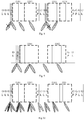
Fig. 7 shows a schematic diagram of a detection mode of a network equipment when a time domain transmission unit contains only one SSB; -
Fig. 8 shows a schematic diagram of a detection mode and SSB transmission for SSB with a subcarrier space of 30 kHz when a time domain transmission unit contains two consecutive SSBs; -
Fig. 9 shows a schematic diagram of a detection mode and SSB transmission for SSB with a subcarrier space of 30 kHz when a time domain transmission unit contains two discontinuous SSBs; -
Fig. 10 shows a schematic diagram of a detection mode and SSB transmission for SSB when a time domain transmission unit contains four SSBs; -
Fig. 11 shows a schematic diagram of a detection mode and SSB transmission for SSB of high frequency band; -
Fig. 12 shows a schematic diagram of a detection mode and SSB transmission for a network equipment when a time domain transmission unit contains the PDCCH and the SSB; -
Fig. 13 shows a schematic diagram of a detection mode and SSB transmission when a network equipment performs omnidirectional channel detection or sector channel detection; -
Fig. 14 is a schematic diagram of modules of a network equipment according to an embodiment of the present disclosure; and -
Fig. 15 is a structural block diagram of a network equipment according to an embodiment of the present disclosure. - Hereinafter, the technical solutions in the embodiments of the present disclosure will be described clearly and thoroughly in conjunction with the drawings in the embodiments of the present disclosure. Obviously, the described embodiments are part of the embodiments of the present disclosure, but not all of the embodiments. Based on the embodiments in the present disclosure, all other embodiments obtained by a person of ordinary skill in the art without creative efforts should fall within the protection scope of the present disclosure.
- The terms "first", "second", etc. in the specification and claims of this application are used to distinguish similar objects, and are not necessarily used to describe a specific sequence or priority. It should be understood that the data used in this way can be interchanged under appropriate circumstances so that the embodiments of the present application described herein, for example, can be implemented in a sequence other than those illustrated or described herein. In addition, the terms "comprising and "having" and any variations thereof are intended to cover non-exclusive inclusions. For example, processes, methods, systems, products or devices that include a series of steps or units is not necessarily limited to those clearly listed steps or units, but may include other steps or units that are not clearly listed or are inherent to these processes, methods, products, or devices. In addition, the use of "and/or" in the specification and claims means at least one of the connected objects, for example, A and/or B, which means three situations: A is included alone, B is included alone, and both A and B are included.
- In the embodiments of the present disclosure, words such as "exemplary" or "for example" are used to represent examples, illustrations, or explanations. Any embodiment or design solution described as "exemplary" or "for example" in the embodiments of the present disclosure should not be construed as being more advantageous than other embodiments or design solutions. To be precise, the use of word "exemplary" or "for example" or the like is intended to present related concepts in a specific manner.
- The following describes embodiments of the present disclosure in conjunction with the drawings. The signal transmitting method and the network equipment provided by the embodiments of the present disclosure can be applied to a wireless communication system. The wireless communication system may be a system adopting a fifth generation (5G) mobile communication technology (hereinafter referred to as 5G system), and those skilled in the art can understand that the 5G NR system is only an example and not a limitation.
- In the description of the embodiments of the present disclosure, some concepts used in the following description are first explained.
- The subcarrier space of SSB of low frequency band (a frequency band below 6 GHz) may be 15 kHz/30 kHz, and at least one or two symbols at the beginning in a slot of 14 symbols are reserved for downlink (DL) control. At least 2 symbols at the end are reserved for guard period (GP) and uplink (UL) control. There are at most two possible SSB time locations in a slot of 14 symbols. In the high frequency band (a frequency band higher than 6 GHz), the subcarrier space of SSB is 120 kHz/240 kHz. When the subcarrier space of the SSB is 120 kHz, at least 2 symbols at the beginning in a slot of 14 symbols are reserved for DL control. At least 2 symbols at the end are reserved for guard period (GP) and UL control. There are at most two possible SSB time locations in a slot of 14 symbols. When the subcarrier space of SSB is 240 kHz, the SSBs will be mapped to two consecutive slots of 14 symbols. At least 4 symbols at the beginning in the first slot are reserved for DL control. At least 4 symbols at the end of the second slot are reserved for guard period and UL control. There are at most 4 possible SSB time locations in two consecutive slots of 14 symbols. The transmission patterns of SSB in the related art are shown in
Figs. 1 to 5 , whereFig. 1 is a schematic diagram of a pattern of SSB with a subcarrier space of 15 kHz,Fig. 2 is a schematic diagram of a first pattern of SSB with a subcarrier space of 30 kHz,Fig. 3 is a schematic diagram of a second pattern of SSB with a subcarrier space of 30 kHz,Fig. 4 is a schematic diagram of a pattern of SSB with a subcarrier space of 120 kHz,Fig. 5 is a schematic diagram of a pattern of SSB with a subcarrier space of 240 kHz. Among them, different SSBs can be transmitted by beamforming in different directions, and each SSB corresponds to a beam, and the beam can also be called a spatial domain transmission filter. - On the unlicensed band, there are two types of downlink channel access procedures. One is LBT based on backoff mechanism, which is applicable to Physical Downlink Control Channel (PDCCH)/Physical Downlink Shared Channel (PDSCH)/Enhanced Physical Downlink Control Channel (EPDCCH); when a channel is detected to be idle during the defer duration and counter N is zero, the base station can start a transmission. Another access mechanism is for the discovery signal (not including data transmission). When the channel is detected to be idle in one clear channel assessment (CCA), it can immediately start a transmission of no more than 1 ms. The base station also needs to perform channel detection before transmitting the SSB. At least one of the two channel access mechanisms must be satisfied. The parameters of the channel access mechanism may be adjusted according to the frequency band where the SSB is located or the subcarrier space of SSB.
- In the embodiments of the present disclosure, channel detection is performed on the transmission direction of each SSB in the time domain transmission unit before a time domain transmission unit, and corresponding SSBs are sequentially transmitted in the transmission directions in which the channel is detected to be idle in the time domain transmission unit; a channel reservation signal is transmitted in all transmission directions of SSB in which transmission is not performed and the channel is idle.
- Specifically, as shown in
Fig. 6 , it is a schematic diagram of a flowchart of a signal transmitting method according to an embodiment of the present disclosure. The signal transmitting method is applied to a network equipment and includes: -
Step 601, performing channel detection on a time domain transmission unit, on an unlicensed band;
It should be noted that, the channel detection here refers to perform LBT on the time domain transmission unit. The time domain transmission unit includes at least one synchronization signal block (SSB), that is, the smallest unit of the time domain transmission unit may be the transmission time of one SSB, that is, 4 Orthogonal Frequency Division Multiplexing (OFDM) symbols. - Step 602, transmitting a synchronization signal block (SSB) according to a detection result of the channel detection;
It should be noted that, on the unlicensed band, when it is listened, according to the detection result of the time domain transmission unit, that a channel in a transmission direction of a target SSB is idle, the target SSB is transmitted in the transmission direction of the target SSB within the OFDM symbols of the target SSB, thereby achieving the transmission of the SSB on the unlicensed band. - Furthermore, the network equipment may specifically perform the channel detection as follows: performing channel detection in a transmission direction of at least one SSB contained in the time domain transmission unit.
- It should be noted here that, when performing channel detection on these SSBs, the network equipment needs to perform channel detection in the transmission directions of the SSBs. The time domain transmission unit may contain only one SSB, or two SSBs, or more than two SSBs. When the time domain transmission unit has only one SSB, the network equipment simply needs to perform channel detection in the transmission direction of this SSB; when the time domain transmission unit has two SSBs or more than two SSBs, the network equipment needs to perform channel detection in the transmission direction of each of the SSBs, in other words, no matter how many SSBs are contained in the time domain transmission unit, the network equipment needs to perform channel detection in the transmission directions of all the SSBs contained in the time domain transmission unit.
- Because the content contained in the time domain transmission unit is different, the specific implementation of the signal transmitting method in the embodiment of the present disclosure will also be different. Hereinafter, from the perspective of the specific content contained in the time domain transmission unit, the specific implementations of the embodiment of the present disclosure are described as follows.
- In this case, the network equipment needs to perform channel detection before each SSB is transmitted.
- For example, for the SSB transmission pattern of 15 kHz or the second SSB transmission pattern of 30 kHz, the time domain transmission unit may be 4 OFDM symbols. Before transmitting each SSB, the network equipment listens in the transmission direction of the SSB. Specifically, as shown in
Fig. 7 , the network equipment performs channel detection in an OFDM symbol before each SSB. A dotted box inFig. 7 represents a time domain transmission unit, and the time domain transmission unit contains only one SSB. A slash-filled box represents an OFDM symbol that the time domain transmission unit listens to. - It should be noted here that, because the transmission time of SSB is very short, channel detection of one clear channel assessment (CCA) (for example, one shot LBT) may be used without backoff. The channel detection time may be 25 µs or less, for example, 16 µs, or 9 µs.
- It should be noted that, when the time domain transmission unit contains at least two SSBs, an implementation of
Step 601 may be as follows:
performing channel detection in transmission directions of the at least two SSBs simultaneously. - In this case, the at least two SSBs may be consecutive SSBs, or may be discontinuous SSBs. Digital beamforming is adopted for each of the at least two SSBs, that is, only the SSBs of low frequency band can realize simultaneous channel detection in the transmission directions of multiple SSBs.
- Specifically, in this case, a specific implementation of Step 602 is:
when it is listened that a channel in a transmission direction of at least one second SSB after a first SSB among the at least two SSBs is idle, transmitting a channel reservation signal of the at least one second SSB in the transmission direction of the at least one second SSB within orthogonal frequency division multiplexing (OFDM) symbols of the first SSB. - For example, for the SSB patterns shown in
Figs. 1 to 3 , the time transmission unit may be selected as multiple consecutive SSBs. The network equipment simultaneously performs channel detection in the transmission directions of multiple SSBs before the time domain transmission unit, and transmits SSB in a direction where the channel is idle. Specifically, as shown inFig. 8 , it shows an SSB pattern with a subcarrier space of 30 kHz. Since the frequency band below 6 GHz may be used for digital beamforming, the network equipment can transmit and receive in different directions. Before every two consecutive SSBs, channel detection is performed on the transmission directions of SSBs simultaneously. InFig. 8 , before the transmission of SSB1 and SSB2, the transmission directions of SSB1 and SSB2 are listened to. When the channel detection result of the transmission direction of SSB1 is busy, and the channel detection result of the transmission direction of SSB2 is idle, the SSB1 cannot be transmitted while the SSB2 can be transmitted. However, in order to prevent the channel for SSB2 from being occupied by other Radio Access Technologies (RAT) or other transmission nodes during the transmission time of SSB1, any channel reservation signal may be transmitted in the transmission direction of SSB2 within OFDM symbols of SSB1. If it is detected that the SSB whose channel is busy is the latter of two consecutive SSBs, the former SSB is transmitted normally, and the latter SSB is not transmitted, as shown in SSB3 and SSB4 inFig. 8 , where the slash-filled boxes represent OFDM symbols that the time domain transmission unit listens to. - It should also be noted that for low frequency SSBs, the time domain transmission unit may also be selected as multiple discontinuously transmitted SSBs, as shown in
Fig. 9 . InFig. 9 , two discontinuous SSBs are selected as a time domain transmission unit for detection, that is to say, the duration of the time domain transmission unit is from the start symbol of SSB1 to the end symbol of SSB2. If the channels in the transmission directions of SSB1 and SSB2 are both idle, then within OFDM symbols of SSB1, SSB1 is transmitted in the transmission direction of SSB1, and the channel reservation signal is transmitted in the transmission direction of SSB2. Within the symbols between the SSB1 and the SSB2, the channel reservation signal is transmitted in the transmission direction of SSB2, and SSB2 is transmitted within OFDM symbols of SSB2, where the slash-filled box represents an OFDM symbol for time domain transmission unit detection. - If the length of the time domain transmission unit is greater than one slot, for example, spans two time slots, as shown in
Fig. 10 , the time domain transmission unit is selected as being from the start OFDM symbol of SSB1 to the end OFDM symbol of SSB4. If channels in all transmission directions are detected as idle, the network equipment must transmit channel reservation signals in the transmission directions of all SSBs that are not transmitted at the same time when transmitting the SSBs. The channel reservation signals are also transmitted on the DL symbols between SSBs. No transmission is performed or no channel reservation signal is transmitted in the reserved gaps or UL OFDM symbols. It should be noted that, when the channels in the transmission directions of some SSBs are detected as busy, the SSBs in the transmission directions may not be transmitted, and only the channel reservation signals in the transmission directions of the SSBs whose channels are detected as idle are transmitted, where the slash-filled box in the figure represents an OFDM symbol for time domain transmission unit detection. - It should be noted that, when the time domain transmission unit contains at least two SSBs, another implementation of
Step 601 may be as follows:
performing channel detection in the transmission directions of the at least two SSBs sequentially. - It should be noted that, in this case, the at least two SSBs may be consecutive SSBs, or may be discontinuous SSBs. Either digital beamforming or analog beamforming is adopted for the at least two SSBs. However, it should be noted here that, since the SSB of high frequency band adopts analog beamforming, only one direction of beam can be sent at the same time, and the network equipment cannot perform channel detection in all directions at one time. Thus, for at least two SSBs of high frequency band, the network equipment needs to perform channel detection in the transmission directions of individual SSBs sequentially; for the SSB of low frequency band, the network equipment can either perform channel detection in the transmission direction of each SSB simultaneously, or perform channel detection in the transmission directions of individual SSBs sequentially.
- Specifically, when analog beamforming is adopted for each of the at least two SSBs, a specific implementation of Step 602 is:
when it is listened that a channel in a transmission direction of a third SSB among the at least two SSBs is busy and there is a fourth SSB after the third SSB, transmitting a channel reservation signal of the fourth SSB in a transmission direction of the fourth SSB within OFDM symbols of the third SSB. - For example, for the SSBs of high frequency band, channel detection may be performed in the transmission directions of individual SSBs sequentially before the time domain transmission unit, and then the SSB may be transmitted in the transmission direction where the channel is idle, as shown in
Fig. 11 . If the transmission direction of SSB1 is busy, the channel reservation signal may be transmitted in the transmission direction of SSB2 within OFDM symbols of SSB1, where the slash-filled boxes in the figure represent OFDM symbols that the time domain transmission unit listens to. - III. The time domain transmission unit includes the SSB and physical downlink control channel (PDCCH)
- It should be noted that, in this case, a specific implementation of
Step 601 is:
performing channel detection in transmission directions of the PDCCH and the SSB in the time domain transmission unit. - For example, when the network equipment has a PDCCH to be transmitted, the time domain transmission unit may include PDCCH and SSB. As shown in
Fig. 12 , taking a pattern of SSB with a subcarrier space of 15 kHz or a second pattern of SSB with a subcarrier space of 30 kHz as an example, for the first SSB of each slot, channel detection is performed in the transmission direction of the PDCCH and the transmission direction of the SSB in the last OFDM symbol of the previous slot. For the second SSB in a slot, channel detection is performed within OFDM symbols of the second SSB before the SSB in a slot. Wherein, the vertical filled boxes inFig. 12 represent PDCCH transmission symbols, the dash-dotted boxes represent intervals and PUCCH transmission symbols, and the slash-filled boxes are OFDM symbols that are listened by the time domain transmission unit. - It should be noted here that, if the transmission direction of the PDCCH is the same as the transmission direction of the first SSB in the slot, only one direction of channel detection is required. For the first pattern of SSB with a subcarrier space of 30 kHz, the detection method is similar, and will not be repeated here.
- It should be noted that, in this case, a specific implementation of
Step 601 is:
performing channel detection in transmission directions of the PDCCH and the PDSCH of the target information and the SSB in the time domain transmission unit, wherein the target information includes at least one of: remaining minimum system information (RMSI), other system information (OSI), and paging signaling. - It should be noted that, for the time domain transmission unit of this format, channel detection is performed simultaneously or sequentially for the transmission directions of these signals when detection, and then time division multiplexing (TDM) or frequency division multiplexing (FDM) is used to transmit these signals.
- It should also be noted that,
Step 601 in the embodiment of the present disclosure may also be implemented as follows: - performing omnidirectional channel detection or sector channel detection on the time domain transmission unit;
- wherein the omnidirectional channel detection adopts an omnidirectional antenna for detection;
- the sector channel detection adopts a sector antenna for detection.
- For example, as shown in
Fig. 13 , omnidirectional channel detection or sector channel detection is performed on the DL symbols before the time domain transmission unit. When the channel is listened to be idle, all the SSBs in the time domain transmission unit can be transmitted. It should be noted that, when performing sector channel detection, the direction of the sector needs to cover the transmission directions of all the SSBs in the time domain transmission unit, where the slash-filled boxs represent OFDM symbols that the time domain transmission unit listens to. - It should be noted that, for directional transmission, it is assumed that ED is a power detection threshold set based on a gain of the spatial domain transmission filter. When adopting omnidirectional channel detection or sector channel detection, since the gain of the omnidirectional antenna or sector antenna is different from a gain based on the spatial domain transmission filter, it is necessary to adjust the power detection threshold or power detection method to match the channel detection with the transmitted power matched.
- For ease of implementation, in the embodiment of the present disclosure, without changing the power detection threshold, a detection time of omnidirectional channel detection or sector channel detection is acquired as follows: the detection time of the omnidirectional channel detection or the sector channel detection is acquired according to a difference between the gain of the target antenna, and the gain of the SSB based on the spatial domain transmission filter, wherein the target antenna is: an omnidirectional antenna or a sector antenna.
- For example, assuming that a CCA slot based on the spatial domain transmission filter is 25 µs, the antenna gain of the spatial domain transmission filter is 3 dB larger than the gain of the sector antenna. In order to compensate for the antenna gain difference of 3dB, the time of the CCA slot may be adjusted to 50 µs.
- In addition, it should also be noted that, in the embodiment of the present disclosure, the channel detection can not only use one CCA channel detection, but also can use channel detection based on the backoff mechanism when the time domain transmission unit is long.
- It should be noted that, the above embodiment of the present disclosure can solve the problem of transmitting SSBs on unlicensed bands, thereby improving the network communication process, ensuring the normal RRM measurement and initial access of the terminal, and improving the reliability of network communication.
- As shown in
Fig. 14 , an embodiment of the present disclosure further provides anetwork equipment 1400, which includes: - a
detection module 1401 configured to perform channel detection on a time domain transmission unit, on an unlicensed band; - a
transmitting module 1402 configured to transmit a synchronization signal block (SSB) according to a detection result of the channel detection; - wherein the time domain transmission unit includes at least one SSB.
- Optionally, the
detection module 1401 is configured to:
perform channel detection in a transmission direction of at least one SSB contained in the time domain transmission unit. - Optionally, when the time domain transmission unit includes at least two SSBs, the
detection module 1401 is configured to:
perform channel detection in transmission directions of the at least two SSBs simultaneously. - Specifically, digital beamforming is adopted for each of the at least two SSBs.
- Optionally, the
transmitting module 1402 is configured to:
when it is listened that a channel in a transmission direction of at least one second SSB after a first SSB among the at least two SSBs is idle, transmit a channel reservation signal of the at least one second SSB in the transmission direction of the at least one second SSB within orthogonal frequency division multiplexing (OFDM) symbols of the first SSB. - Optionally, when the time domain transmission unit includes at least two SSBs, the
detection module 1401 is configured to:
perform channel detection in transmission directions of the at least two SSBs sequentially. - Further, when analog beamforming is adopted for each of the at least two SSBs, the
transmitting module 1402 is configured to:
when it is listened that a channel in a transmission direction of a third SSB among the at least two SSBs is busy and there is a fourth SSB after the third SSB, transmitting a channel reservation signal of the fourth SSB in a transmission direction of the fourth SSB within OFDM symbols of the third SSB. - Optionally, when the time domain transmission unit further includes a physical downlink control channel (PDCCH), the
detection module 1401 is configured to:
perform channel detection in transmission directions of the PDCCH and the SSB in the time domain transmission unit. - Optionally, when the time domain transmission unit further includes a PDCCH and a physical downlink sharing channel (PDSCH) of target information, the
detection module 1401 is configured to:
perform channel detection in transmission directions of the PDCCH and the PDSCH of the target information and the SSB in the time domain transmission unit, wherein the target information includes at least one of: remaining minimum system information (RMSI), other system information (OSI), and paging signaling. - Optionally, the
detection module 1401 is configured to: - perform omnidirectional channel detection or sector channel detection on the time domain transmission unit;
- wherein the omnidirectional channel detection adopts an omnidirectional antenna for detection, and the sector channel detection adopts a sector antenna for detection.
- Further, a detection time of the omnidirectional channel detection or the sector channel detection is acquired as follows: the detection time of the omnidirectional channel detection or the sector channel detection is acquired according to a difference between a gain of a target antenna, and a gain of the SSB based on a spatial domain transmission filter;
wherein the target antenna is: an omnidirectional antenna or a sector antenna. - Further, the channel detection adopts one of: channel detection of one clear channel assessment (CCA) and channel detection based on backoff mechanism.
- Further, the
transmitting module 1402 is configured to:
when it is listened that a channel in a transmission direction of a target SSB is idle, transmit the target SSB in the transmission direction of the target SSB within OFDM symbols of the target SSB. - It should be noted that, this network equipment embodiment is a network equipment corresponding to the above signal transmitting method applied to the network equipment side. All the implementations of the above-mentioned embodiment are applicable to this network equipment embodiment, and can also achieve the same technical effects.
- An embodiment of the present disclosure further provides a network equipment including: a storage, a processor, and a computer program stored on the storage and capable of running on the processor; the computer program implements, when executed by the processor, the processes in the above signal transmitting method embodiment applied to a network equipment, and can achieve the same technical effects. To avoid repetition, they will not be described again here.
- An embodiment of the present disclosure further provides a computer readable storage medium, wherein the computer readable storage medium stores a computer program thereon, and when executed by a processor, the computer program implements the processes in the above signal transmitting method embodiment applied to a network equipment, and can achieve the same technical effects. To avoid repetition, they will not be described again here. The computer readable storage medium may be such as a Read-Only Memory (ROM), a Random Access Memory (RAM), a magnetic disks or an optical disks, etc.
-
Fig. 15 is a structural diagram of a network equipment according to an embodiment of the present disclosure, which can implement the details of the above signal transmitting method applied to a network equipment side, and achieve the same effects. As shown inFig. 15 , thenetwork equipment 1500 includes: aprocessor 1501, atransceiver 1502, astorage 1503 and a bus interface, wherein: - the
processor 1501 is configured to read a program stored in thestorage 1503 and perform the following processes: - performing channel detection on a time domain transmission unit, on an unlicensed band;
- transmitting a synchronization signal block (SSB) via the
transceiver 1502 according to a detection result of the channel detection; - wherein the time domain transmission unit includes at least one SSB.
- In
Fig. 15 , the bus architecture may include any number of interconnected buses and bridges, which are linked together specifically by various circuits such as one or more processors represented by the processor 1001 and the storage represented by the storage 1003. The bus architecture can also link various other circuits such as peripheral devices, voltage regulators, and power management circuits, etc., which are well known in the art, and therefore, they will not be further described herein. The bus interface provides interfaces. Thetransceiver 1502 may be a plurality of elements, including a transmitter and a receiver, and provides units for communicating with various other devices on a transmission medium. - The
processor 1501 is responsible for managing the bus architecture and general processing, and thestorage 1503 may store data used by theprocessor 1501 when performing operations. - Optionally, the
processor 1501 further reads the program stored in thestorage 1503 to perform:
performing channel detection in a transmission direction of at least one SSB contained in the time domain transmission unit. - Optionally, when the time domain transmission unit includes at least two SSBs, the
processor 1501 further reads the program stored in thestorage 1503 to perform:
performing channel detection in transmission directions of the at least two SSBs simultaneously. - Wherein digital beamforming is adopted for each of the at least two SSBs.
- Optionally, the
processor 1501 further reads the program stored in thestorage 1503 to perform:
when it is listened that a channel in a transmission direction of at least one second SSB after a first SSB among the at least two SSBs is idle, transmitting a channel reservation signal of the at least one second SSB in the transmission direction of the at least one second SSB within orthogonal frequency division multiplexing (OFDM) symbols of the first SSB. - Optionally, when the time domain transmission unit includes at least two SSBs, the
processor 1501 further reads the program stored in thestorage 1503 to perform:
performing channel detection in transmission directions of the at least two SSBs sequentially. - Optionally, when analog beamforming is adopted for each of the at least two SSBs, the
processor 1501 further reads programs stored in thestorage 1503 to perform:
when it is listened that a channel in a transmission direction of a third SSB among the at least two SSBs is busy and there is a fourth SSB after the third SSB, transmitting a channel reservation signal of the fourth SSB in a transmission direction of the fourth SSB within OFDM symbols of the third SSB. - Optionally, the
processor 1501 further reads programs stored in thestorage 1503 to perform:
performing channel detection in transmission directions of the PDCCH and the SSB in the time domain transmission unit. - Optionally, when the time domain transmission unit further includes a PDCCH and a physical downlink sharing channel (PDSCH) of target information, the
processor 1501 further reads programs stored in thestorage 1503 to perform:
performing channel detection in transmission directions of the PDCCH and the PDSCH of the target information and the SSB in the time domain transmission unit, wherein the target information includes at least one of: remaining minimum system information (RMSI), other system information (OSI), and paging signaling. - Optionally, the
processor 1501 further reads programs stored in thestorage 1503 to perform: - performing omnidirectional channel detection or sector channel detection on the time domain transmission unit;
- wherein the omnidirectional channel detection adopts an omnidirectional antenna for detection, and the sector channel detection adopts a sector antenna for detection.
- wherein a detection time of the omnidirectional channel detection or the sector channel detection is acquired as follows: the detection time of the omnidirectional channel detection or the sector channel detection is acquired according to a difference between a gain of a target antenna, and a gain of the SSB based on a spatial domain transmission filter; wherein the target antenna is: an omnidirectional antenna or a sector antenna.
- Specifically, the channel detection adopts one of: channel detection of one clear channel assessment (CCA), and channel detection based on backoff mechanism.
- Optionally, the
processor 1501 further reads programs stored in thestorage 1503 to perform:
when it is listened that a channel in a transmission direction of a target SSB is idle, transmitting the target SSB in the transmission direction of the target SSB within OFDM symbols of the target SSB via thetransceiver 1502. - Wherein, the network equipment may be a base station (Base Transceiver Station, BTS) in Global System of Mobile communication (GSM) or Code Division Multiple Access (CDMA), or may be a base station (NodeB, NB) in (Wideband Code Division Multiple Access, WCDMA), or may also be a base station (Evolutional Node B, eNB or eNodeB) in LTE, or a relay station or access point, or a base station in a future 5G network etc., which is not limited here.
- It should be noted that, the terms "comprising", "including" herein or any other variants thereof are intended to cover non-exclusive inclusion, so that processes, methods, articles or devices including a series of elements not only includes those elements, but also includes other elements not explicitly listed, or elements inherent to the processes, methods, articles, or devices. Without more restrictions, the element defined by the sentence "comprising a..." does not exclude that there are other identical elements in the process, method, article, or terminal equipment that includes the element.
- With the description of the above embodiments, those skilled in the art can clearly understand that the methods in the above embodiments can be implemented by means of software plus a necessary general hardware platform, and of course, can also be implemented by hardware, but in many cases the former is a preferred implementation. Based on such an understanding, the essential technical solutions of the present disclosure, or part of the technical solutions that contributes to the related art, can be embodied in the form of a software product; the computer software product is stored in a storage medium (such as a ROM/RAM, a magnetic disk, or an optical disk), including several instructions used to cause a terminal (which may be a mobile phone, a computer, a server, an air conditioner, or a network equipment, etc.) to perform the methods described in various embodiments of the present disclosure.
- The above are optional implementations of the present disclosure. It should be noted that, for those of ordinary skill in the art, many improvements and modifications can be made without departing from the principles described in this disclosure, and these improvements and modifications are also within the protection scope of this disclosure.
Claims (28)
- A signal transmitting method applied to a network equipment, comprising:performing channel detection on a time domain transmission unit on an unlicensed band;transmitting a synchronization signal block (SSB) according to a detection result of the channel detection, wherein the time domain transmission unit comprises at least one SSB.
- The signal transmitting method according to claim 1, wherein the performing channel detection on the time domain transmission unit comprises:
performing channel detection in a transmission direction of at least one SSB contained in the time domain transmission unit. - The signal transmitting method according to claim 1, wherein, when the time domain transmission unit comprises at least two SSBs, the performing channel detection on the time domain transmission unit comprises:
performing channel detection in transmission directions of the at least two SSBs simultaneously. - The signal transmitting method according to claim 3, wherein digital beamforming is adopted for each of the at least two SSBs.
- The signal transmitting method according to claim 3, wherein the transmitting the synchronization signal block (SSB) according to the detection result of the channel detection comprises:
when it is listened that a channel in a transmission direction of at least one second SSB after a first SSB among the at least two SSBs is idle, transmitting a channel reservation signal of the at least one second SSB in the transmission direction of the at least one second SSB within orthogonal frequency division multiplexing (OFDM) symbols of the first SSB. - The signal transmitting method according to claim 1, wherein, when the time domain transmission unit comprises at least two SSBs, the performing channel detection on the time domain transmission unit comprises:
performing channel detection in transmission directions of the at least two SSBs sequentially. - The signal transmitting method according to claim 6, wherein, when analog beamforming is adopted for each of the at least two SSBs, the transmitting the synchronization signal block (SSB) according to the detection result of the channel detection comprises:
when it is listened that a channel in a transmission direction of a third SSB among the at least two SSBs is busy and there is a fourth SSB after the third SSB, transmitting a channel reservation signal of the fourth SSB in a transmission direction of the fourth SSB within OFDM symbols of the third SSB. - The signal transmitting method according to claim 1, wherein, when the time domain transmission unit further comprises a physical downlink control channel (PDCCH), the performing channel detection on the time domain transmission unit comprises:
performing channel detection in transmission directions of the PDCCH and the SSB in the time domain transmission unit. - The signal transmitting method according to claim 1, wherein, when the time domain transmission unit further comprises a PDCCH and a physical downlink sharing channel (PDSCH) of target information, the performing channel detection on the time domain transmission unit comprises:
performing channel detection in transmission directions of the PDCCH and the PDSCH of the target information and the SSB in the time domain transmission unit, wherein the target information comprises at least one of: remaining minimum system information (RMSI), other system information (OSI), and paging signaling. - The signal transmitting method according to claim 1, wherein the performing channel detection on the time domain transmission unit comprises:performing omnidirectional channel detection or sector channel detection on the time domain transmission unit;wherein the omnidirectional channel detection adopts an omnidirectional antenna for detection, and the sector channel detection adopts a sector antenna for detection.
- The signal transmitting method according to claim 10, wherein a detection time of the omnidirectional channel detection or the sector channel detection is acquired as follows: the detection time of the omnidirectional channel detection or the sector channel detection is acquired according to a difference between a gain of a target antenna, and a gain of the SSB based on a spatial domain transmission filter;
wherein the target antenna is: an omnidirectional antenna or a sector antenna. - The signal transmitting method according to claim 1, wherein the channel detection adopts channel detection of one clear channel assessment (CCA) or channel detection based on backoff mechanism.
- The signal transmitting method according to any of claims 1 to 12, wherein the transmitting the synchronization signal block (SSB) according to the detection result of the channel detection comprises:
when it is listened that a channel in a transmission direction of a target SSB is idle, transmitting the target SSB in the transmission direction of the target SSB within OFDM symbols of the target SSB. - A network equipment, comprising:a detection module configured to perform channel detection on a time domain transmission unit on an unlicensed band;a transmitting module configured to transmit a synchronization signal block (SSB) according to a detection result of the channel detection, wherein the time domain transmission unit comprises at least one SSB.
- The network equipment according to claim 14, wherein the detection module is configured to:
perform channel detection in a transmission direction of at least one SSB contained in the time domain transmission unit. - The network equipment according to claim 14, wherein, when the time domain transmission unit comprises at least two SSBs, the detection module is configured to:
perform channel detection in transmission directions of the at least two SSBs simultaneously. - The network equipment according to claim 16, wherein digital beamforming is adopted for each of the at least two SSBs.
- The network equipment according to claim 16, wherein the transmitting module is configured to:
when it is listened that a channel in a transmission direction of at least one second SSB after a first SSB among the at least two SSBs is idle, transmit a channel reservation signal of the at least one second SSB in the transmission direction of the at least one second SSB within orthogonal frequency division multiplexing (OFDM) symbols of the first SSB. - The network equipment according to claim 14, wherein, when the time domain transmission unit comprises at least two SSBs, the detection module is configured to:
perform channel detection in transmission directions of the at least two SSBs sequentially. - The network equipment according to claim 19, wherein, when analog beamforming is adopted for each of the at least two SSBs, the transmitting module is configured to:
when it is listened that a channel in a transmission direction of a third SSB among the at least two SSBs is busy and there is a fourth SSB after the third SSB, transmitting a channel reservation signal of the fourth SSB in a transmission direction of the fourth SSB within OFDM symbols of the third SSB. - The network equipment according to claim 14, wherein, when the time domain transmission unit further comprises a physical downlink control channel (PDCCH), the detection module is configured to:
perform channel detection in transmission directions of the PDCCH and the SSB in the time domain transmission unit. - The network equipment according to claim 14, wherein, when the time domain transmission unit further comprises a PDCCH and a physical downlink sharing channel (PDSCH) of target information, the detection module is configured to:
perform channel detection in transmission directions of the PDCCH and the PDSCH of the target information and the SSB in the time domain transmission unit, wherein the target information comprises at least one of: remaining minimum system information (RMSI), other system information (OSI), and paging signaling. - The network equipment according to claim 14, wherein the detection module is configured to:perform omnidirectional channel detection or sector channel detection on the time domain transmission unit;wherein the omnidirectional channel detection adopts an omnidirectional antenna for detection, and the sector channel detection adopts a sector antenna for detection.
- The network equipment according to claim 23, wherein a detection time of the omnidirectional channel detection or the sector channel detection is acquired as follows: the detection time of the omnidirectional channel detection or the sector channel detection is acquired according to a difference between a gain of a target antenna, and a gain of the SSB based on a spatial domain transmission filter;
wherein the target antenna is: an omnidirectional antenna or a sector antenna. - The network equipment according to claim 14, wherein the channel detection adopts channel detection of one clear channel assessment (CCA) or channel detection based on backoff mechanism.
- The network equipment according to any of claims 14 to 25, wherein the transmitting module is configured to:
when it is listened that a channel in a transmission direction of a target SSB is idle, transmit the target SSB in the transmission direction of the target SSB within OFDM symbols of the target SSB. - A network equipment, comprising a storage, a processor, and a computer program stored on the storage and capable of running on the processor, the computer program implementing, when executed by the processor, the steps of the signal transmitting method according to any of claims 1 to 13.
- A computer readable storage medium having a computer program stored thereon, the computer program implementing, when executed by a processor, the steps of the signal transmitting method according to any of claims 1 to 13.
Applications Claiming Priority (2)
| Application Number | Priority Date | Filing Date | Title |
|---|---|---|---|
| CN201810247834.0A CN110300442B (en) | 2018-03-23 | 2018-03-23 | Signal sending method and network equipment |
| PCT/CN2019/075189 WO2019179263A1 (en) | 2018-03-23 | 2019-02-15 | Signal sending method and network device |
Publications (2)
| Publication Number | Publication Date |
|---|---|
| EP3771128A1 true EP3771128A1 (en) | 2021-01-27 |
| EP3771128A4 EP3771128A4 (en) | 2021-05-19 |
Family
ID=67986640
Family Applications (1)
| Application Number | Title | Priority Date | Filing Date |
|---|---|---|---|
| EP19772111.1A Pending EP3771128A4 (en) | 2018-03-23 | 2019-02-15 | SIGNAL SENDING PROCESS AND NETWORK DEVICE |
Country Status (4)
| Country | Link |
|---|---|
| US (1) | US12219505B2 (en) |
| EP (1) | EP3771128A4 (en) |
| CN (1) | CN110300442B (en) |
| WO (1) | WO2019179263A1 (en) |
Cited By (1)
| Publication number | Priority date | Publication date | Assignee | Title |
|---|---|---|---|---|
| US20220360418A1 (en) * | 2019-07-18 | 2022-11-10 | Datang Mobile Communications Equipment Co.,Ltd. | Method for detecting downlink control channel, method for transmitting downlink control channel, and relevant devices |
Families Citing this family (9)
| Publication number | Priority date | Publication date | Assignee | Title |
|---|---|---|---|---|
| WO2019191897A1 (en) * | 2018-04-03 | 2019-10-10 | Oppo广东移动通信有限公司 | Clear channel listening method and apparatus, and device |
| CN114175832B (en) * | 2019-08-09 | 2024-09-20 | 联想(北京)有限公司 | Method and device for sharing channel occupancy time |
| CN111010742B (en) * | 2019-12-09 | 2022-07-15 | Oppo广东移动通信有限公司 | Method and terminal device for determining random access resources |
| US12250724B2 (en) | 2019-12-25 | 2025-03-11 | Beijing Xiaomi Mobile Software Co., Ltd. | Data transmission method and device, and computer storage medium |
| CN111669238B (en) * | 2020-05-15 | 2022-03-29 | 中国信息通信研究院 | High-frequency discovery signal transmission method, device and system |
| CN111669239B (en) * | 2020-05-15 | 2022-09-09 | 中国信息通信研究院 | A method, device and system supporting directional listen-before-send transmission |
| CN116318584A (en) * | 2020-07-27 | 2023-06-23 | 大唐移动通信设备有限公司 | Method, device and equipment for broadcast data transmission |
| US20230217383A1 (en) * | 2022-01-06 | 2023-07-06 | Mediatek Singapore Pte. Ltd. | Data-aided ssb signal processing |
| CN114501610B (en) * | 2022-04-02 | 2022-07-15 | 北京云智软通信息技术有限公司 | Cell synchronization method and device |
Family Cites Families (30)
| Publication number | Priority date | Publication date | Assignee | Title |
|---|---|---|---|---|
| US20040157645A1 (en) * | 2003-02-12 | 2004-08-12 | Smith Adrian David | System and method of operation an array antenna in a distributed wireless communication network |
| EP2929592A4 (en) * | 2012-12-10 | 2016-08-17 | Intel Corp | MODULAR ANTENNA ARRAY WITH RF BEAM AND BASEBAND FORMATION |
| US10057779B2 (en) * | 2014-06-13 | 2018-08-21 | Qualcomm Incorporated | Techniques for enhancing frame structure and listen before talk procedure (LBT) for transmissions using an unlicensed radio frequency spectrum band |
| CN105162563B (en) * | 2014-08-25 | 2020-07-10 | 中兴通讯股份有限公司 | Method and device for transmitting and receiving unauthorized carrier information |
| US9647864B2 (en) * | 2015-04-10 | 2017-05-09 | Motorola Mobility Llc | Method and apparatus for reception of control signaling |
| US10531488B2 (en) * | 2015-08-11 | 2020-01-07 | Lg Electronics Inc. | Method for transmitting/receiving wireless signal in wireless communication system and device therefor |
| US10917913B2 (en) * | 2015-10-26 | 2021-02-09 | Intel IP Corporation | Apparatus, system and method of communication based on clear channel assessment (CCA) in one or more directions |
| CN106992804A (en) * | 2016-01-20 | 2017-07-28 | 中兴通讯股份有限公司 | The sending method and device of a kind of detection reference signal |
| EP3840277B1 (en) * | 2016-04-25 | 2022-12-07 | Electronics and Telecommunications Research Institute | Method for transmitting discovery signals and method for receiving discovery signals |
| US10959264B2 (en) * | 2016-07-19 | 2021-03-23 | Lg Electronics Inc. | Method for transmitting frame in wireless LAN system and wireless terminal using same |
| MY202521A (en) * | 2016-08-10 | 2024-05-02 | Interdigital Patent Holdings Inc | Methods and apparatus for efficient power saving in wireless networks |
| CN110024338B (en) * | 2016-09-30 | 2021-06-25 | 中兴通讯股份有限公司 | Techniques for Improving EDCA Mechanism in Spatial Multiplexing |
| KR102412727B1 (en) * | 2016-09-30 | 2022-06-24 | 삼성전자 주식회사 | Signal transmission/reception method and device |
| US10257848B2 (en) * | 2016-10-04 | 2019-04-09 | Qualcomm Incorporated | Directional channel reservation for time-division multiplexing downlink and uplink data burst transmission |
| US11115983B2 (en) * | 2016-11-11 | 2021-09-07 | Qualcomm Incorporated | Data and control channels in synchronization bursts for millimeter wave new radio |
| US10368301B2 (en) * | 2017-02-21 | 2019-07-30 | Qualcomm Incorporated | Multi-beam and single-beam discovery reference signals for shared spectrum |
| WO2018152985A1 (en) * | 2017-02-27 | 2018-08-30 | 华为技术有限公司 | Data transmission method and user equipment |
| US10462761B2 (en) * | 2017-07-25 | 2019-10-29 | Samsung Electronics Co., Ltd. | Method and SS block time locations and SS burst set composition for NR unlicensed spectrum |
| US10687356B2 (en) * | 2017-08-08 | 2020-06-16 | Qualcomm Incorporated | Channel reservation signal in NR shared spectrum |
| US10925091B2 (en) * | 2017-08-16 | 2021-02-16 | Qualcomm Incorporated | Listen-before-talk (LBT) with new radio-spectrum sharing (NR-SS) discovery signal transmission |
| CN107528682B (en) * | 2017-09-20 | 2020-12-22 | 宇龙计算机通信科技(深圳)有限公司 | Reference signal transmission method and device |
| US10959105B2 (en) * | 2017-09-29 | 2021-03-23 | Qualcomm Incorporated | Methods, apparatuses and systems for configuring bandwidth parts in shared spectrum |
| US10764896B2 (en) * | 2017-11-08 | 2020-09-01 | Samsung Electronics Co., Ltd. | Method and apparatus for beam management in the unlicensed spectrum |
| CN107820259B (en) * | 2017-11-09 | 2021-06-18 | 宇龙计算机通信科技(深圳)有限公司 | A beam-based channel idle determination method and device |
| US11324047B2 (en) * | 2017-11-10 | 2022-05-03 | Qualcomm Incorporated | NR-unlicensed transmission opportunity structure with flexible starting point |
| US10785799B2 (en) * | 2017-11-20 | 2020-09-22 | Qualcomm Incorporated | Adaptive medium sensing thresholds |
| WO2019119249A1 (en) * | 2017-12-19 | 2019-06-27 | 南通朗恒通信技术有限公司 | Method and apparatus used in user equipment and base station for wireless communication |
| US10405263B2 (en) * | 2018-02-05 | 2019-09-03 | Verizon Patent And Licensing Inc. | Private radio networks |
| US10912129B2 (en) * | 2018-02-08 | 2021-02-02 | Qualcomm Incorporated | SSB multiplexing and RMSI monitoring in NR-U |
| WO2019160741A1 (en) * | 2018-02-14 | 2019-08-22 | Idac Holdings, Inc. | Methods, apparatus, and system using multiple antenna techniques for new radio (nr) operations in unlicensed bands |
-
2018
- 2018-03-23 CN CN201810247834.0A patent/CN110300442B/en active Active
-
2019
- 2019-02-15 EP EP19772111.1A patent/EP3771128A4/en active Pending
- 2019-02-15 WO PCT/CN2019/075189 patent/WO2019179263A1/en not_active Ceased
- 2019-02-15 US US17/040,826 patent/US12219505B2/en active Active
Cited By (2)
| Publication number | Priority date | Publication date | Assignee | Title |
|---|---|---|---|---|
| US20220360418A1 (en) * | 2019-07-18 | 2022-11-10 | Datang Mobile Communications Equipment Co.,Ltd. | Method for detecting downlink control channel, method for transmitting downlink control channel, and relevant devices |
| US12113748B2 (en) * | 2019-07-18 | 2024-10-08 | Datang Mobile Communications Equipment Co., Ltd. | Method for detecting downlink control channel, method for transmitting downlink control channel, and relevant devices |
Also Published As
| Publication number | Publication date |
|---|---|
| US12219505B2 (en) | 2025-02-04 |
| US20210022095A1 (en) | 2021-01-21 |
| CN110300442B (en) | 2020-07-28 |
| EP3771128A4 (en) | 2021-05-19 |
| CN110300442A (en) | 2019-10-01 |
| WO2019179263A1 (en) | 2019-09-26 |
Similar Documents
| Publication | Publication Date | Title |
|---|---|---|
| US12219505B2 (en) | Signal transmitting method and network equipment | |
| EP3536075B1 (en) | Solving deafness in directional clear channel assessment (cca) | |
| US12375934B2 (en) | Network node and method for dynamic spectrum sharing between radio access technologies | |
| US9788320B2 (en) | Scanning secondary cells in cellular communications system | |
| US11844109B2 (en) | Controlling AUL transmissions when coexisting with scheduled UEs | |
| US10820355B2 (en) | Method and apparatus for random access in mobile communication system | |
| US11622283B2 (en) | Wireless communication system with discrimination between extraneous received signals | |
| EP3253165B1 (en) | Processing method and device for discovery signal | |
| EP3413676B1 (en) | Method and device for transmitting prach signals in unauthorized spectrum | |
| US12471116B2 (en) | Method and apparatus for resource allocation for sidelink communication | |
| US10631326B2 (en) | Scheduling method, data transmission method, and apparatus | |
| EP4007428B1 (en) | Random access method, device, and medium | |
| US12238656B2 (en) | Rate matching indication method and apparatus, and device and storage medium | |
| EP3771127B1 (en) | Signal transmission method and network device | |
| US20250280435A1 (en) | Time gap adjustment for channel access procedure by user devices for a sidelink communication in an unlicensed spectrum | |
| US20250331006A1 (en) | Sidelink slot structure | |
| EP3445122B1 (en) | Signal sending method and apparatus, and resource notification method and apparatus | |
| US12114275B2 (en) | Synchronization signal/PBCH block transmission method, receiving method, apparatus, device, and medium | |
| RU2792774C1 (en) | Signaling method and network device | |
| US10827447B2 (en) | Method and device for transmitting uplink | |
| WO2025213432A1 (en) | Random access channel transmission in subband non-overlapping full duplex | |
| KR20250056065A (en) | Device and method for allocating resource | |
| HK40078766B (en) | Apparatuses and methods for wireless communications | |
| HK40078766A (en) | Apparatuses and methods for wireless communications |
Legal Events
| Date | Code | Title | Description |
|---|---|---|---|
| STAA | Information on the status of an ep patent application or granted ep patent |
Free format text: STATUS: THE INTERNATIONAL PUBLICATION HAS BEEN MADE |
|
| PUAI | Public reference made under article 153(3) epc to a published international application that has entered the european phase |
Free format text: ORIGINAL CODE: 0009012 |
|
| STAA | Information on the status of an ep patent application or granted ep patent |
Free format text: STATUS: REQUEST FOR EXAMINATION WAS MADE |
|
| 17P | Request for examination filed |
Effective date: 20201013 |
|
| AK | Designated contracting states |
Kind code of ref document: A1 Designated state(s): AL AT BE BG CH CY CZ DE DK EE ES FI FR GB GR HR HU IE IS IT LI LT LU LV MC MK MT NL NO PL PT RO RS SE SI SK SM TR |
|
| AX | Request for extension of the european patent |
Extension state: BA ME |
|
| A4 | Supplementary search report drawn up and despatched |
Effective date: 20210415 |
|
| RIC1 | Information provided on ipc code assigned before grant |
Ipc: H04L 5/00 20060101AFI20210409BHEP Ipc: H04W 74/08 20090101ALI20210409BHEP Ipc: H04B 7/06 20060101ALI20210409BHEP |
|
| DAV | Request for validation of the european patent (deleted) | ||
| DAX | Request for extension of the european patent (deleted) | ||
| STAA | Information on the status of an ep patent application or granted ep patent |
Free format text: STATUS: EXAMINATION IS IN PROGRESS |
|
| 17Q | First examination report despatched |
Effective date: 20230615 |
|
| REG | Reference to a national code |
Ref country code: DE Ref legal event code: R079 Free format text: PREVIOUS MAIN CLASS: H04L0005000000 Ipc: H04W0074080800 |
|
| RIC1 | Information provided on ipc code assigned before grant |
Ipc: H04W 74/0808 20240101AFI20260209BHEP Ipc: H04W 48/12 20090101ALI20260209BHEP Ipc: H04L 5/00 20060101ALI20260209BHEP Ipc: H04L 27/00 20060101ALI20260209BHEP Ipc: H04W 24/08 20090101ALI20260209BHEP Ipc: H04W 48/16 20090101ALI20260209BHEP |
|
| GRAP | Despatch of communication of intention to grant a patent |
Free format text: ORIGINAL CODE: EPIDOSNIGR1 |
|
| STAA | Information on the status of an ep patent application or granted ep patent |
Free format text: STATUS: GRANT OF PATENT IS INTENDED |
|
| INTG | Intention to grant announced |
Effective date: 20260319 |