EP3770995A1 - Single-cell battery, battery module, power battery and electric vehicle - Google Patents
Single-cell battery, battery module, power battery and electric vehicle Download PDFInfo
- Publication number
- EP3770995A1 EP3770995A1 EP19772632.6A EP19772632A EP3770995A1 EP 3770995 A1 EP3770995 A1 EP 3770995A1 EP 19772632 A EP19772632 A EP 19772632A EP 3770995 A1 EP3770995 A1 EP 3770995A1
- Authority
- EP
- European Patent Office
- Prior art keywords
- plate
- cell according
- section
- support plate
- electrode tab
- Prior art date
- Legal status (The legal status is an assumption and is not a legal conclusion. Google has not performed a legal analysis and makes no representation as to the accuracy of the status listed.)
- Withdrawn
Links
- 125000006850 spacer group Chemical group 0.000 claims abstract description 51
- 230000007704 transition Effects 0.000 claims description 18
- 238000003466 welding Methods 0.000 description 8
- 230000002708 enhancing effect Effects 0.000 description 5
- 238000005452 bending Methods 0.000 description 4
- 238000010586 diagram Methods 0.000 description 3
- 239000000463 material Substances 0.000 description 2
- 241001391944 Commicarpus scandens Species 0.000 description 1
- 238000004891 communication Methods 0.000 description 1
- 230000006872 improvement Effects 0.000 description 1
- 238000009413 insulation Methods 0.000 description 1
- 230000007774 longterm Effects 0.000 description 1
- 238000004519 manufacturing process Methods 0.000 description 1
- 239000002184 metal Substances 0.000 description 1
- 238000012986 modification Methods 0.000 description 1
- 230000004048 modification Effects 0.000 description 1
- 238000007493 shaping process Methods 0.000 description 1
Images



Classifications
-
- H—ELECTRICITY
- H01—ELECTRIC ELEMENTS
- H01M—PROCESSES OR MEANS, e.g. BATTERIES, FOR THE DIRECT CONVERSION OF CHEMICAL ENERGY INTO ELECTRICAL ENERGY
- H01M50/00—Constructional details or processes of manufacture of the non-active parts of electrochemical cells other than fuel cells, e.g. hybrid cells
- H01M50/50—Current conducting connections for cells or batteries
- H01M50/528—Fixed electrical connections, i.e. not intended for disconnection
-
- H—ELECTRICITY
- H01—ELECTRIC ELEMENTS
- H01M—PROCESSES OR MEANS, e.g. BATTERIES, FOR THE DIRECT CONVERSION OF CHEMICAL ENERGY INTO ELECTRICAL ENERGY
- H01M50/00—Constructional details or processes of manufacture of the non-active parts of electrochemical cells other than fuel cells, e.g. hybrid cells
- H01M50/50—Current conducting connections for cells or batteries
- H01M50/528—Fixed electrical connections, i.e. not intended for disconnection
- H01M50/529—Intercell connections through partitions, e.g. in a battery casing
-
- H—ELECTRICITY
- H01—ELECTRIC ELEMENTS
- H01M—PROCESSES OR MEANS, e.g. BATTERIES, FOR THE DIRECT CONVERSION OF CHEMICAL ENERGY INTO ELECTRICAL ENERGY
- H01M10/00—Secondary cells; Manufacture thereof
- H01M10/36—Accumulators not provided for in groups H01M10/05-H01M10/34
- H01M10/38—Construction or manufacture
-
- H—ELECTRICITY
- H01—ELECTRIC ELEMENTS
- H01M—PROCESSES OR MEANS, e.g. BATTERIES, FOR THE DIRECT CONVERSION OF CHEMICAL ENERGY INTO ELECTRICAL ENERGY
- H01M50/00—Constructional details or processes of manufacture of the non-active parts of electrochemical cells other than fuel cells, e.g. hybrid cells
- H01M50/10—Primary casings; Jackets or wrappings
- H01M50/147—Lids or covers
-
- H—ELECTRICITY
- H01—ELECTRIC ELEMENTS
- H01M—PROCESSES OR MEANS, e.g. BATTERIES, FOR THE DIRECT CONVERSION OF CHEMICAL ENERGY INTO ELECTRICAL ENERGY
- H01M50/00—Constructional details or processes of manufacture of the non-active parts of electrochemical cells other than fuel cells, e.g. hybrid cells
- H01M50/10—Primary casings; Jackets or wrappings
- H01M50/147—Lids or covers
- H01M50/148—Lids or covers characterised by their shape
- H01M50/15—Lids or covers characterised by their shape for prismatic or rectangular cells
-
- H—ELECTRICITY
- H01—ELECTRIC ELEMENTS
- H01M—PROCESSES OR MEANS, e.g. BATTERIES, FOR THE DIRECT CONVERSION OF CHEMICAL ENERGY INTO ELECTRICAL ENERGY
- H01M50/00—Constructional details or processes of manufacture of the non-active parts of electrochemical cells other than fuel cells, e.g. hybrid cells
- H01M50/10—Primary casings; Jackets or wrappings
- H01M50/147—Lids or covers
- H01M50/155—Lids or covers characterised by the material
-
- H—ELECTRICITY
- H01—ELECTRIC ELEMENTS
- H01M—PROCESSES OR MEANS, e.g. BATTERIES, FOR THE DIRECT CONVERSION OF CHEMICAL ENERGY INTO ELECTRICAL ENERGY
- H01M50/00—Constructional details or processes of manufacture of the non-active parts of electrochemical cells other than fuel cells, e.g. hybrid cells
- H01M50/10—Primary casings; Jackets or wrappings
- H01M50/172—Arrangements of electric connectors penetrating the casing
- H01M50/174—Arrangements of electric connectors penetrating the casing adapted for the shape of the cells
- H01M50/176—Arrangements of electric connectors penetrating the casing adapted for the shape of the cells for prismatic or rectangular cells
-
- H—ELECTRICITY
- H01—ELECTRIC ELEMENTS
- H01M—PROCESSES OR MEANS, e.g. BATTERIES, FOR THE DIRECT CONVERSION OF CHEMICAL ENERGY INTO ELECTRICAL ENERGY
- H01M50/00—Constructional details or processes of manufacture of the non-active parts of electrochemical cells other than fuel cells, e.g. hybrid cells
- H01M50/40—Separators; Membranes; Diaphragms; Spacing elements inside cells
- H01M50/471—Spacing elements inside cells other than separators, membranes or diaphragms; Manufacturing processes thereof
- H01M50/477—Spacing elements inside cells other than separators, membranes or diaphragms; Manufacturing processes thereof characterised by their shape
-
- H—ELECTRICITY
- H01—ELECTRIC ELEMENTS
- H01M—PROCESSES OR MEANS, e.g. BATTERIES, FOR THE DIRECT CONVERSION OF CHEMICAL ENERGY INTO ELECTRICAL ENERGY
- H01M50/00—Constructional details or processes of manufacture of the non-active parts of electrochemical cells other than fuel cells, e.g. hybrid cells
- H01M50/50—Current conducting connections for cells or batteries
- H01M50/531—Electrode connections inside a battery casing
- H01M50/533—Electrode connections inside a battery casing characterised by the shape of the leads or tabs
-
- H—ELECTRICITY
- H01—ELECTRIC ELEMENTS
- H01M—PROCESSES OR MEANS, e.g. BATTERIES, FOR THE DIRECT CONVERSION OF CHEMICAL ENERGY INTO ELECTRICAL ENERGY
- H01M50/00—Constructional details or processes of manufacture of the non-active parts of electrochemical cells other than fuel cells, e.g. hybrid cells
- H01M50/50—Current conducting connections for cells or batteries
- H01M50/572—Means for preventing undesired use or discharge
- H01M50/584—Means for preventing undesired use or discharge for preventing incorrect connections inside or outside the batteries
-
- H—ELECTRICITY
- H01—ELECTRIC ELEMENTS
- H01M—PROCESSES OR MEANS, e.g. BATTERIES, FOR THE DIRECT CONVERSION OF CHEMICAL ENERGY INTO ELECTRICAL ENERGY
- H01M50/00—Constructional details or processes of manufacture of the non-active parts of electrochemical cells other than fuel cells, e.g. hybrid cells
- H01M50/50—Current conducting connections for cells or batteries
- H01M50/572—Means for preventing undesired use or discharge
- H01M50/584—Means for preventing undesired use or discharge for preventing incorrect connections inside or outside the batteries
- H01M50/59—Means for preventing undesired use or discharge for preventing incorrect connections inside or outside the batteries characterised by the protection means
- H01M50/593—Spacers; Insulating plates
-
- H—ELECTRICITY
- H01—ELECTRIC ELEMENTS
- H01M—PROCESSES OR MEANS, e.g. BATTERIES, FOR THE DIRECT CONVERSION OF CHEMICAL ENERGY INTO ELECTRICAL ENERGY
- H01M2220/00—Batteries for particular applications
- H01M2220/20—Batteries in motive systems, e.g. vehicle, ship, plane
-
- Y—GENERAL TAGGING OF NEW TECHNOLOGICAL DEVELOPMENTS; GENERAL TAGGING OF CROSS-SECTIONAL TECHNOLOGIES SPANNING OVER SEVERAL SECTIONS OF THE IPC; TECHNICAL SUBJECTS COVERED BY FORMER USPC CROSS-REFERENCE ART COLLECTIONS [XRACs] AND DIGESTS
- Y02—TECHNOLOGIES OR APPLICATIONS FOR MITIGATION OR ADAPTATION AGAINST CLIMATE CHANGE
- Y02E—REDUCTION OF GREENHOUSE GAS [GHG] EMISSIONS, RELATED TO ENERGY GENERATION, TRANSMISSION OR DISTRIBUTION
- Y02E60/00—Enabling technologies; Technologies with a potential or indirect contribution to GHG emissions mitigation
- Y02E60/10—Energy storage using batteries
-
- Y—GENERAL TAGGING OF NEW TECHNOLOGICAL DEVELOPMENTS; GENERAL TAGGING OF CROSS-SECTIONAL TECHNOLOGIES SPANNING OVER SEVERAL SECTIONS OF THE IPC; TECHNICAL SUBJECTS COVERED BY FORMER USPC CROSS-REFERENCE ART COLLECTIONS [XRACs] AND DIGESTS
- Y02—TECHNOLOGIES OR APPLICATIONS FOR MITIGATION OR ADAPTATION AGAINST CLIMATE CHANGE
- Y02P—CLIMATE CHANGE MITIGATION TECHNOLOGIES IN THE PRODUCTION OR PROCESSING OF GOODS
- Y02P70/00—Climate change mitigation technologies in the production process for final industrial or consumer products
- Y02P70/50—Manufacturing or production processes characterised by the final manufactured product
Definitions
- a shape of the head 14 of the inner spacer 10 is not limited thereto, and the head 14 of the inner spacer 10 may further be elliptical, drop-shaped, etc., so as to reduce damage to the electrode tab 21.
- the connecting plate is a ring surrounding the bottom plate, and the clamping plate is connected to the connecting plate and is disposed coplanar with the support plate.
Landscapes
- Chemical & Material Sciences (AREA)
- Chemical Kinetics & Catalysis (AREA)
- Electrochemistry (AREA)
- General Chemical & Material Sciences (AREA)
- Engineering & Computer Science (AREA)
- Manufacturing & Machinery (AREA)
- Connection Of Batteries Or Terminals (AREA)
- Sealing Battery Cases Or Jackets (AREA)
Abstract
Description
- This application claims priority to Chinese Patent Application Serial No. "
201820409789.X - The present disclosure belongs to the technical field of vehicle manufacturing, and relates to a cell and a battery module provided with the cell, a power battery provided with the battery module, and an electric vehicle provided with the power battery.
- Generally, a power battery has at least two conductive terminals, and one end is connected to the conductive terminal by using a double-layer connector, and the other end is configured to clamp an electrode tab to be connected to a pole core, so that a circuit is powered on. In the related art, the connector clamping the electrode tab drives the tag to bend. Side spacers on both sides of a cover plate fixe and insulate the tag, but occupy at least a thickness of four layers of the connectors in a height direction, not facilitating increase of space utilization of a battery cell. The double-layer connector only clamps an end part of the electrode tab, and cannot effectively shape other parts of the electrode tab, especially a bent region. In addition, a tip of the double-layer connector is attached to the electrode tab. When the cell is under extreme conditions such as collision or vibration, the electrode tab may be cut, and even internal resistance in the cell may be increase and heat is generated abnormally, so that a risk of causing a safety accident is caused, and there is room for improvement.
- The present disclosure is intended to resolve at least one of technical problems existing in the prior art. Accordingly, the present disclosure provides a cell, and an inner spacer of the cell supports, insulates, and shapes an electrode tab and is not easy to cut the electrode tab.
- The cell according to an embodiment of the present disclosure includes: a housing; a cover plate located at an end of the housing; a pole core located in the housing and having an electrode tab; an inner spacer including a bottom plate, a connecting plate, and a support plate, where the bottom plate is disposed on a surface of the pole core facing the cover plate, one end of the connecting plate is connected to a side edge of the bottom plate and is formed in a bent shape with a side edge of the bottom plate, the other end of the connecting plate is connected to the support plate and is formed in a bent shape with the support plate, and the support plate extends toward a direction away from the bottom plate, a part of the electrode tab extending from a side surface of the support plate facing the pole core to a side surface away from the pole core; and a conductive terminal disposed on the cover plate and electrically connected to a side surface of the electrode tab away from the support plate.
- For the cell according to an embodiment of the present disclosure, the inner spacer is disposed between the pole core and the conductive terminal. The inner spacer may support the electrode tab, and insulate and shape the electrode tab simultaneously, and prevent the electrode tab and the core from being short-circuited. In addition, the electrode tab is directly connected to the conductive terminal by welding, and the electrode tab is connected to the conductive terminal without the connector, reducing a space occupied by the cell in a height direction, increasing space utilization of the cell, and enhancing practicability of the cell.
- The present disclosure further provides a battery module, including a connector and the cell in any of the foregoing embodiments, and the cells are connected in series or in parallel through a connector.
- The present disclosure further provides a power battery, including a pack body and a battery module disposed in the pack body, and the battery module is the battery module described in the foregoing embodiment.
- The present disclosure further provides an electric vehicle provided with the power battery described in the foregoing embodiment.
- Compared to the prior art, advantages of the battery module, the power battery, the electric vehicle, and the foregoing cell are the same, and are not described herein again.
- Additional aspects and advantages of the present disclosure will be given in the following description, some of which will become apparent from the following description or may be learned from practices of the present disclosure.
- The foregoing and/or additional aspects and advantages of the present disclosure will become apparent and comprehensible from the following descriptions of the embodiments with reference to the accompanying drawings., where:
-
FIG. 1 andFIG. 2 are schematic structural diagrams of a cell according to an embodiment of the present disclosure; -
FIG. 3 is a schematic structural diagram of an inner spacer of the cell according to an embodiment of the present disclosure; -
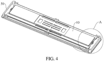
FIG. 4 is a schematic structural diagram of clamping of the inner spacer of the cell with an insulating plate according to an embodiment of the present disclosure; and -
FIG. 5 is a partially enlarged view of part A inFIG. 4 . -
Inner spacer 10,Bottom plate 11, Connectingplate 12,Support plate 13,Head 14,First section 141,Second section 142,Third section 143, Avoidinggroove 15,Clamping plate 16,Positioning slot 161,
Pole core 20, Electrodetab 21,
Transition plate 30,Housing 40,Cover plate 50,Insulating plate 60,Buckle 61, Connectingpost 611,Clamping portion 612, Guide surface 6121, andConductive terminal 70. - The following describes embodiments of the present disclosure in detail. Examples of the embodiments are shown in the accompanying drawings, and same or similar reference signs in all the accompanying drawings indicate same or similar components or components having same or similar functions. The embodiments described below with reference to the accompanying drawings are exemplary, and are intended to explain the present disclosure and cannot be construed as a limitation to the present disclosure.
- In the description of the present disclosure, it should be understood that orientation or position relationships indicated by the terms such as "length", "width", "thickness", ""above", "below", "front", "back", "left", "right", "vertical", and "horizontal" "top", "bottom", "inside", "outside", and "circumferential" are based on orientation or position relationships shown in the accompanying drawings, and are used only for ease of describing the present disclosure and for ease of simplified descriptions, rather than indicating or implying that the mentioned apparatus or component needs to have a particular orientation or needs to be constructed and operated in a particular orientation. Therefore, such terms should not be construed as limiting of the present disclosure. In addition, a feature defined to be "first" or "second" may explicitly or implicitly include one or more features. In the description of the present disclosure, unless stated otherwise, the meaning of "a plurality of" is two or more than two.
- In the description of the present disclosure, it should be noted that unless otherwise explicitly specified or defined, the terms such as "mount", "install", "connect", and "connection" should be understood in a broad sense. For example, the connection may be a fixed connection, a detachable connection, or an integral connection; or the connection may be a mechanical connection; or the connection may be a direct connection, an indirect connection through an intermediary, or internal communication between two components. A person of ordinary skill in the art may understand the specific meanings of the foregoing terms in the present disclosure according to specific situations.
- A
cell 100 according to an embodiment of the present disclosure is described below with reference toFIG. 1 to FIG. 3 . - As shown in
FIG. 1 to FIG. 2 , thecell 100 according to an embodiment of the present disclosure includes: ahousing 40, acover plate 50, apole core 20, and aninner spacer 10. - The
cover plate 50 is located at an end of thehousing 40. Thepole core 20 is disposed inside thecell 100, thepole core 20 is located in thehousing 40, thepole core 20 has aelectrode tab 21, and thepole core 20 is connected to aconductive terminal 70 of thecell 100 through theelectrode tab 21. For example, theelectrode tab 21 is connected to theconductive terminal 70 of thecell 100 by welding to implement current guidance of thepole core 20 and acover plate 50 assembly and ensure normal current conduction between thepole core 20 and thecover plate 50 assembly. - As shown in
FIG. 1 andFIG. 2 , theinner spacer 10 may be configured to separate theconductive terminal 70 of thecell 100 from thepole core 20 to effectively insulate theconductive terminal 70 from thepole core 20. As shown inFIG. 3 , theinner spacer 10 includes abottom plate 11, a connectingplate 12, and asupport plate 13. Thebottom plate 11 is supported by thepole core 20. Thebottom plate 11 is disposed on a surface of thepole core 20 facing thecover plate 50. One end of the connectingplate 12 is connected to an edge of thebottom plate 11, and the one end of the connectingplate 12 and a side edge of thebottom plate 11 are formed in a shape. In other words, a direction in which the connectingplate 12 extends is different from a direction in which thebottom plate 11 extends. For example, thebottom plate 11 extends in a horizontal direction, and theconnecting plate 12 extends toward a height direction of the cell 1 00. - As shown in
FIG. 1 andFIG. 2 , thesupport plate 13 is connected to the other end of the connectingplate 12, and thesupport plate 13 and the other end of the connectingplate 12 are formed in a bent shape, that is, thesupport plate 13 and thebottom plate 11 are connected through theconnecting plate 12. Thesupport plate 13 extends toward a direction away from thebottom plate 11, and a certain height difference is formed between thesupport plate 13 and thebottom plate 11. It may be understood that the height difference between thesupport plate 13 and thebottom plate 11 may facilitate that theelectrode tab 21 protrudes from an upper surface of thepole core 20, theelectrode tab 21 extends to a lower surface of thesupport plate 13 and bends, and then extends along the lower surface of thesupport plate 13 toward a direction away from thebottom plate 11. In this way, thesupport plate 13, the connectingplate 12, and thebottom plate 11 are sequentially connected as a whole, and a part of theelectrode tab 21 extends from a side surface of thesupport plate 13 facing thepole core 20 to a side surface away from thepole core 20. In an embodiment, theelectrode tab 21 extends along the lower surface of thesupport plate 13 toward a direction away from thebottom plate 11, and theelectrode tab 21 bypasses the end of thesupport plate 13 and extends to an upper surface of thesupport plate 13, thereby effectively shaping theelectrode tab 21, especially the bent portion of the electrode tab. - It should be noted that in
FIG. 3 , both ends of thebottom plate 11 are provided with a connectingplate 12 and asupport plate 13. In other words, theinner spacer 10 includes twoconnecting plates 12, twosupport plates 13, and abottom plate 11. In this way, theinner spacer 10 may be simultaneously fitted with twoelectrode tabs 21 through mounting, to support and insulate theelectrode tabs 21 of thepole core 20 and ensure normal current conduction between theelectrode tabs 21 and theconductive terminal 70. - As shown in
FIG. 1 andFIG. 2 , theconductive terminal 70 is disposed on thecover plate 50, and theconductive terminal 70 is electrically connected to a side surface of theelectrode tab 21 away from thesupport plate 13. In other words, after theelectrode tab 21 is bent and bypasses thesupport plate 13 to extend, an upper surface of theelectrode tab 21 is attached to and connected, by welding, to theconductive terminal 70. Therefore, theelectrode tab 21 contacts theconductive terminal 70 in a large contact area, effectively increasing overcurrent capability of theelectrode tab 21 and theconductive terminal 70, and improving practical performance of thecell 100. Theconductive terminal 70 is connected to thecover plate 50 in an insulated and sealed manner. In this way, there is no current conduction between theconductive terminal 70 and thecover plate 50. - In an embodiment, as shown in
FIG. 1 andFIG. 2 , theelectrode tab 21 of thepole core 20 may be directly connected to theconductive terminal 70 by welding, theinner spacer 10 supports theelectrode tab 21 below theelectrode tab 21 and separates theelectrode tab 21 from the pole core 20 a height direction, to achieve effective insulation, and theelectrode tab 21 is bent along an outer side of theinner spacer 10. In this way, theelectrode tab 21 is directly welded to theconductive terminal 70 without a connector, reducing space occupied in the height direction and effectively improving space utilization of thecell 100. - For the
cell 100 according to this embodiment of the present disclosure, theinner spacer 10 is disposed between thepole core 20 and theconductive terminal 70. Theinner spacer 10 may support theelectrode tab 21, and insulate and shape theelectrode tab 21 simultaneously, and prevent theelectrode tab 21 and the core 20 from being short-circuited. In addition, theelectrode tab 21 is directly connected to theconductive terminal 70 by welding, and theelectrode tab 21 is connected to theconductive terminal 70 without the connector, reducing a space occupied by thecell 100 in a height direction, increasing space utilization of thecell 100, and enhancing practicability of thecell 100. - For the
cell 100 according to this embodiment of the present disclosure, as shown inFIG. 1 andFIG. 2 , atransition plate 30 is further included and thetransition plate 30 has a through hole. The conductive terminal 70 sequentially passes through thecover plate 50 and the through hole, and theconductive terminal 70 is connected to thetransition plate 30 by welding, and a side surface of thetransition plate 30 away from thecover plate 50 is connected to a side surface of the electrode tab away from thesupport plate 13. In this way, theconductive terminal 70 is connected to theelectrode tab 21 through thetransition plate 30 to conduct current between theconductive terminal 70 of thecell 100 and thepole core 20. - In an embodiment, as shown in
FIG. 1 andFIG. 2 , thecell 100 of the present disclosure further includes an insulatingplate 60. The insulatingplate 60 is located between thecover plate 50 and thetransition plate 30, the insulatingplate 60 has fixing hole, and the conductive terminal 70 passes through the fixing hole to fix the insulatingplate 60. Therefore, the conductive terminal 70 sequentially passes through thecover plate 50, the fixing hole of the insulatingplate 60, and the through hole of thetransition plate 30, and is connected to theelectrode tab 21. At the same time, theconductive terminal 70, the insulatingplate 60, thetransition plate 30, and theelectrode tab 21 are relatively fixed to ensure that an overall structure inside thecell 100 is complete. - As shown in
FIG. 4 andFIG. 5 , theinner spacer 10 is fixedly connected to the insulatingplate 60 through clamping. In an embodiment, an end of theinner spacer 10 is provided with apositioning slot 161, the insulatingplate 60 has abuckle 61, and thebuckle 61 fits thepositioning slot 161 to relatively fix the insulatingplate 60 to theinner spacer 10. Theinner spacer 10 further includes a clampingplate 16, and the clampingplate 16 is disposed on a side edge of thebottom plate 11. In an embodiment, the clampingplate 16 is disposed at both ends of thebottom plate 11 along a length direction, the clampingplate 16 extends along a width direction of thebottom plate 11, and the clampingplate 16 and thesupport plate 13 are located on adjacent sides of thebottom plate 11. It may be understood that thesupport plate 13 is located at both ends of thebottom plate 11 along the width direction, and thesupport plate 13 extends along the length direction of thebottom plate 11. In this way, the clampingplate 16 and thesupport plate 13 are spaced apart along a circumferential direction of thebottom plate 11. Thepositioning slot 161 is disposed at an end of the clampingplate 16 away from thebottom plate 11, and thepositioning slot 161 is located on a surface of the clampingplate 16 facing thepole core 20. In other words, thepositioning slot 161 is located on a surface of the clampingplate 16 away from the insulatingboard 60. An end of the clampingplate 16 is provided with an avoidinggroove 15. It should be noted that the insulatingplate 60 is located on a side surface of the clampingplate 16 away from thepole core 20. Therefore, thebuckle 61 passes through the avoidinggroove 15 from a side of the clampingplate 16 away from thepole core 20, and extends to a side of the clampingplate 16 close to thepole core 20, so that thebuckle 61 is clamped into thepositioning slot 161 of the clampingplate 16, and the insulatingplate 60 is stably and fixedly connected to theinner spacer 10. - In some embodiments, as shown in
FIG. 4 andFIG. 5 , thebuckle 61 includes a connectingpost 611 and a clampingportion 612. One end of the connectingpost 611 is connected to the insulatingplate 60, that is, one end of the connectingpost 611 away from the pole core is fixedly connected to the insulatingplate 60. The clampingportion 612 is connected to the other end of the connectingpost 611, that is, the clampingportion 612 is connected to an end of the connectingpost 611 close to the pole core. In addition, the clampingportion 612 protrudes toward a direction close to the clampingplate 16 and thesupport plate 13, the clampingportion 612 presses against a bottom wall of apositioning groove 161 toward end surfaces of the clampingplate 16 and thesupport plate 13, and an end surface of the clampingportion 612 away from the clampingplate 16 and thesupport plate 13 is provided with a guide surface 6121. The guide surface 6121 may facilitate clamping between thesupport plate 13 and thebuckle 61. - It should be noted that the insulating
plate 60 is provided with two sets ofbuckles 61 disposed opposite to each other, and thesupport plate 13 is provided with two sets of positioningslots 161 disposed opposite to each other. A distance between two sets of clampingportions 612 of the two sets ofbuckles 61 is less than a distance between two ends of thesupport plate 13, and the distance between the two ends of thesupport plate 13 is less than a distance between two sets of connectingposts 611 of the two sets ofbuckles 61. The two sets of clampingportions 612 are provided with guide surfaces 6121 disposed opposite to each other. In this way, an end of thesupport plate 13 is pressed along the guide surface 6121 of the clampingportion 612, the connectingpost 611 is bent under a pressure from the guide surface 6121, an inner spacer is clamped between the two sets of connectingposts 611, and the clampingportion 612 may prevent the inner spacer from detaching from thebuckle 61, improving stability of an overall structure of the cell. - For the
cell 100 according to an embodiment of the present disclosure, as shown inFIG. 1 to FIG. 3 , thebottom plate 11 and thesupport plate 13 are both disposed in a direction parallel to thecover plate 50. For example, thebottom plate 11 is parallel to and attached to thepole core 20 of thecell 100, thesupport plate 13 is connected to thebottom plate 11 through the connectingplate 12, and thesupport plate 13 is formed through extension along a direction parallel to thebottom plate 11. There is a height difference between thebottom plate 11 and thesupport plate 13, and thebottom plate 11 is parallel to thepole core 20, so that there is a distance difference between thesupport plate 13 and thepole core 20. For example, in some embodiments, the connectingplate 12 is perpendicular to thesupport plate 13 and thebottom plate 11, and theelectrode tab 21 is spaced apart from thebottom plate 11 and the connectingplate 12. In other words, a certain space is defined among the connectingplate 12, thesupport plate 13, and thepole core 20. In this way, the defined space may facilitate that theelectrode tab 21 is protruded from thepole core 20 and bent, thereby enhancing rationality of disposing of various components of thecell 100. - In some embodiments, the connecting
plate 12 is a ring surrounding thebottom plate 11, the clampingplate 16 is connected to the connectingplate 12, and the clampingplate 16 is disposed coplanar with thesupport plate 13. It may be understood that theinner spacer 10 includes the clampingplate 16, the connectingplate 12, thebottom plate 11, the connectingplate 12, and the clampingplate 16 that are sequentially connected along a length direction, and theinner spacer 10 includes thesupport plate 13, the connectingplate 12, thebottom plate 11, the connectingplate 12, and thesupport plate 13 that are sequentially connected in a width direction. Therefore, an outer side of thebottom plate 11 is provided with a connectingplate 12 extending in a circumferential direction, and an outer side of the connectingplate 12 is provided with asupport plate 13 and a clampingplate 16 spaced apart and extending in a circumferential direction. Thebottom plate 11, the connectingplate 12, thesupport plate 13, and the clampingplate 16 are integrally formed, facilitating increase of integrality of theinner spacer 10, enhancing structural strength of theinner spacer 10, and facilitating mounting. - For the
cell 100 according to an embodiment of the present disclosure, as shown inFIG. 3 , theinner spacer 10 further includes ahead 14. Thehead 14 is arc-shaped, and thehead 14 is connected to an end of thesupport plate 13 away from the connectingplate 12. At least one part of thehead 14 is arc-shaped, and a thickness of thehead 14 is greater than a thickness of thesupport plate 13. In this way, theelectrode tab 21 extends along a lower surface of thesupport plate 13 toward a direction away from thebottom plate 11 to thehead 14, and theelectrode tab 21 bypasses thehead 14 and extends to an upper surface of thesupport plate 13. A bending curvature of theelectrode tab 21 at a position bypassing thehead 14 is small, that is, a bending stress of theelectrode tab 21 is small, which is not easy to cause theelectrode tab 21 to bend and break. When an arc section of thehead 14 contacts theelectrode tab 21, theelectrode tab 21 is not cut, to prevent theelectrode tab 21 from being cut due to a cutting edge in theinner spacer 10, improving safety of use of thecell 100. - In an embodiment, as shown in
FIG. 3 , a profile of thehead 14 includes afirst section 141, asecond section 142, and athird section 143 that are sequentially connected. An end of thefirst section 141 away from thesecond section 142 is connected to a surface of thesupport plate 13 facing thepole core 20, and an end of thethird section 143 away from thesecond section 142 is connected to a surface of thesupport plate 13 away from thepole core 20, that is, thefirst section 141, thesecond section 142, and thethird section 143 extend from a lower surface of thesupport plate 13 to an upper surface of thesupport plate 13. In this way, theelectrode tab 21 extends along the lower surface of thesupport plate 13 to thefirst section 141, and then extends along an outer surface of thefirst section 141 and sequentially bypasses thesecond section 142 and thethird section 143, so that theelectrode tab 21 is bent and extended to the upper surface of thesupport plate 13, and is then attached to, connected, by welding, to theconductive terminal 70. - As shown in
FIG. 3 , thefirst section 141 is arc-shaped. When theelectrode tab 21 extends along the outside of thefirst section 141, the arc-shapedfirst section 141 does not cut theelectrode tab 21. It should be noted that theelectrode tab 21 is a multilayer metal sheet, and theelectrode tab 21 has relatively low hardness. When theelectrode tab 21 bypasses thehead 14 of theinner spacer 10, theelectrode tab 21 may contact a surface of thehead 14 of theinner spacer 10. In this way, when thecell 100 is under extreme conditions such as collision or vibration, theelectrode tab 21 is not cut by theinner spacer 10, effectively prolonging a service life of theelectrode tab 21, thereby improving use performance of thecell 100. - As shown in
FIG. 3 , thesecond section 142 is linear. In other words, when theelectrode tab 21 bypasses thehead 14 of theinner spacer 10, theelectrode tab 21 extends at least partially along a straight line, and a distance from thesecond section 142 to thepole core 20 is greater than a distance from thesupport plate 13 to thepole core 20, that is, an upper surface of thesecond section 142 is higher than an upper surface of thesupport plate 13. In other words, a thickness of thehead 14 of theinner spacer 10 is greater than a thickness of thesupport plate 13. In this way, when theelectrode tab 21 bypasses thehead 14 of theinner spacer 10, a bent arc of theelectrode tab 21 is great, that is, a bending curvature of theelectrode tab 21 is small. When theelectrode tab 21 is bent, stresses on an inner side of theelectrode tab 21 and an outer side of theelectrode tab 21 are both small, so that theelectrode tab 21 is not easy to break during bending, significantly improving safety performance of use of theelectrode tab 21 and extending a service life of theelectrode tab 21, thereby facilitating long-term use of the electrode tab. - As shown in
FIG. 3 , thethird section 143 is arc-shaped. A radius of curvature of thefirst section 141 is less than a radius of curvature of thethird section 143. When theelectrode tab 21 bypasses thethird section 143, theelectrode tab 21 may not be completely attached to thethird section 143. In this way, after theelectrode tab 21 bypasses thesecond section 142, theelectrode tab 21 extends to the upper surface of thesupport plate 13 by using a radius of curvature less than a radius of curvature of thethird section 143. In other words, there is a small gap between a lower surface of theelectrode tab 21 and thethird section 143. The gap may absorb a part of vibration energy when thecell 100 is under extreme conditions such as collision or vibration, to reduce damage to thecell 100 caused by the external environment, and further facilitating increase of rationality of overall structure design of thecell 100. - In an embodiment, as shown in
FIG. 3 , thethird section 143 includes two arcs. Centers of curvature of the two arcs of thethird section 143 are respectively located on both sides of thethird section 143. For example, a center of curvature of one arc connecting thethird section 143 to thesupport plate 13 is located on a side of thethird section 143 away from thepole core 20, and a center of curvature of the other arc connecting thethird section 143 to thesecond section 142 is located at a side of thethird section 143 close to thepole core 20. In this way, thethird section 143 is formed as a smooth arc-shaped transition between thesupport plate 13 and thesecond section 142, and theelectrode tab 21 is prevented from being cut when thethird section 143 contacts theelectrode tab 21, improving rationality of the overall structure of thecell 100, and enhancing safety of use of theelectrode tab 21. - Definitely, a shape of the
head 14 of theinner spacer 10 is not limited thereto, and thehead 14 of theinner spacer 10 may further be elliptical, drop-shaped, etc., so as to reduce damage to theelectrode tab 21. - In some embodiments, as shown in
FIG. 1 to FIG. 3 , a part of theelectrode tab 21 is located above thebottom plate 11, that is, theelectrode tab 21 extends along the upper surface of thesupport plate 13 to an end of thesupport plate 13 away from thehead 14, and then continues extending. In this way, a length of connection between theelectrode tab 21 and theconductive terminal 70 is great, that is, an area in which theelectrode tab 21 contacts theconductive terminal 70 is great, to effectively enhance overcurrent capability between theelectrode tab 21 and theconductive terminal 70 and improve practicability of thecell 100. In addition, a part of theelectrode tab 21 is spaced from thebottom plate 11, so that the part of theelectrode tab 21 is well attached to theconductive terminal 70. - The present disclosure further provides a battery module provided with the cell of any of the foregoing embodiments, and the cells are connected in series or in parallel through a connector of the cell to form the battery module.
- The present disclosure further provides a power battery.
- The power battery according to an embodiment of the present disclosure is provided with the battery module of the foregoing embodiment.
- The present disclosure further provides an electric vehicle.
- For the electric vehicle according to an embodiment of the present disclosure, the power battery of the foregoing embodiment is disposed. For the electric vehicle according to an embodiment of the present disclosure, an
inner spacer 10 is disposed between apole core 20 and aconductive terminal 70. Theinner spacer 10 may support anelectrode tab 21, and insulate and shape theelectrode tab 21 simultaneously, and prevent theelectrode tab 21 and the core 20 from being short-circuited. In addition, theelectrode tab 21 is directly connected to theconductive terminal 70 by welding, and theelectrode tab 21 is connected to theconductive terminal 70 without a connector, reducing a space occupied by thecell 100 in a height direction, significantly improving use performance of an entire vehicle. - The cell according to an embodiment of the present disclosure includes: a housing; a cover plate located at an end of the housing; a pole core located in the housing and having an electrode tab; an inner spacer including a bottom plate, a connecting plate, and a support plate, where the bottom plate is disposed on a surface of the pole core facing the cover plate, one end of the connecting plate is connected to a side edge of the bottom plate and is formed in a bent shape with a side edge of the bottom plate, the other end of the connecting plate is connected to the support plate and is formed in a bent shape with the support plate, and the support plate extends toward a direction away from the bottom plate, a part of the electrode tab extending from a side surface of the support plate facing the pole core to a side surface away from the pole core; and a conductive terminal disposed on the cover plate and electrically connected to a side surface of the electrode tab away from the support plate.
- The cell according to an embodiment of the present disclosure further includes a transition plate having a through hole, where the conductive terminal sequentially passes through the cover plate and the through hole and is welded to the transition plate, and a side surface of the transition plate away from the cover plate is welded to the side surface of the electrode tab away from the support plate.
- The cell according to an embodiment of the present disclosure further includes an insulating plate, where the insulating plate is located between the cover plate and the transition plate and the insulating plate is provided with a fixing hole, the conductive terminal passing through the fixing hole to fix the insulating plate.
- For the cell according to an embodiment of the present disclosure, the inner spacer is fixedly connected to the insulating plate through clamping.
- For the cell according to an embodiment of the present disclosure, an end of the inner spacer is provided with a positioning slot, and the insulating plate has a buckle that fits the positioning slot.
- For the cell according to an embodiment of the present disclosure, the inner spacer further includes: a clamping plate disposed on a side edge of the bottom plate, where the clamping plate and the support plate are located on adjacent sides of the bottom plate, and the positioning slot is disposed at an end of the clamping plate away from the bottom plate and located on a surface of the clamping plate facing the pole core.
- For the cell according to an embodiment of the present disclosure, the end of the clamping plate is provided with an avoiding groove for avoiding the buckle.
- For the cell according to an embodiment of the present disclosure, the buckle includes: a connecting post, one end of the connecting post being connected to the insulating plate; and a clamping portion connected to the other end of the connecting post and protruding toward a direction close to the clamping plate, an end surface of the clamping portion facing the clamping plate being pressed against a bottom wall of the positioning slot, and an end surface of the clamping portion away from the clamping plate being provided with a guide surface.
- For the cell according to an embodiment of the present disclosure, the connecting plate is a ring surrounding the bottom plate, and the clamping plate is connected to the connecting plate and is disposed coplanar with the support plate.
- For the cell according to an embodiment of the present disclosure, the bottom plate, the connecting plate, the support plate, and the clamping plate are integrally formed.
- For the cell according to an embodiment of the present disclosure, the inner spacer further includes: a head connected to an end of the support plate away from the connecting plate, at least one part of the head being arc-shaped.
- For the cell according to an embodiment of the present disclosure, the head is arc-shaped.
- For the cell according to an embodiment of the present disclosure, a thickness of the head is greater than a thickness of the support plate.
- For the cell according to an embodiment of the present disclosure, a profile of the head includes a first section, a second section, and a third section that are sequentially connected, one end of the first section away from the second section being connected to a surface of the support plate facing the pole core, an end of the third section away from the second section being connected to a surface of the support plate away from the pole core, and the first section being arc-shaped.
- For the cell according to an embodiment of the present disclosure, the second section is linear, a distance from the second section to the pole core being greater than a distance from the support plate to the pole core.
- For the cell according to an embodiment of the present disclosure, the third section is arc-shaped, a radius of curvature of the first section being less than a radius of curvature of the third section.
- For the cell according to an embodiment of the present disclosure, the third section includes two arcs, centers of curvature of the two arcs of the third section being respectively located on both sides of the third section.
- For the cell according to an embodiment of the present disclosure, both the bottom plate and the support plate are disposed in a direction parallel to the cover plate.
- For the cell according to an embodiment of the present disclosure, the connecting plate is perpendicular to the support plate and the bottom plate.
- For the cell according to an embodiment of the present disclosure, the electrode tab is spaced apart from the bottom plate and the connecting plate.
- For the cell according to an embodiment of the present disclosure, a part of the electrode tab is located above the bottom plate and spaced apart from the bottom plate.
- For the cell according to an embodiment of the present disclosure, the conductive terminal is connected to the cover plate in an insulated and sealed manner..
- In the description of this specification, the description of the reference terms such as "an embodiment", "some embodiments", "exemplary embodiments", "example", "specific example", or "some examples" means that the specific features, structures, materials or characteristics described with reference to the embodiment or example are included in at least one embodiment or example of the present disclosure. In this specification, schematic descriptions of the foregoing terms do not necessarily directed at the same embodiment or example. Moreover, the specific features, structures, materials, or characteristics described may be combined in any one or more embodiments or examples in an appropriate manner.
- Although the embodiments of the present disclosure have been shown and described, a person of ordinary skill in the art should understand that various changes, modifications, replacements and variations may be made to the embodiments without departing from the principles and spirit of the present disclosure, and the scope of the present disclosure is as defined by the appended claims and their equivalents.
Claims (25)
- A cell, comprising:a housing;a cover plate located at an end of the housing;a pole core located in the housing and having a electrode tab;an inner spacer comprising a bottom plate, a connecting plate, and a support plate, wherein the bottom plate is disposed on a surface of the pole core facing the cover plate, one end of the connecting plate is connected to a side edge of the bottom plate and is formed in a bent shape with a side edge of the bottom plate, the other end of the connecting plate is connected to the support plate and is formed in a bent shape with the support plate, and the support plate extends toward a direction away from the bottom plate, a part of the electrode tab extending from a side surface of the support plate facing the pole core to a side surface away from the pole core; anda conductive terminal disposed on the cover plate and electrically connected to a side surface of the electrode tab away from the support plate.
- The cell according to claim 1, further comprising: a transition plate having a through hole, wherein the conductive terminal sequentially passes through the cover plate and the through hole and is welded to the transition plate, and a side surface of the transition plate away from the cover plate is welded to a side surface of the electrode tab away from the support plate.
- The cell according to claim 2, further comprising: an insulating plate located between the cover plate and the transition plate and the insulating plate is provided with a fixing hole, wherein the conductive terminal passes through the fixing hole to fix the insulating plate.
- The cell according to claim 3, wherein the inner spacer is fixedly connected to the insulating plate through clamping.
- The cell according to claim 4, wherein an end of the inner spacer is provided with a positioning slot and the insulating plate has a buckle that fits the positioning slot.
- The cell according to claim 5, wherein the inner spacer further comprises: a clamping plate disposed on a side edge of the bottom plate, wherein the clamping plate and the support plate are located on adjacent sides of the bottom plate, and the positioning slot is disposed at an end of the clamping plate away from the bottom plate and located on a surface of the clamping plate facing the pole core.
- The cell according to claim 6, wherein the end of the clamping plate is provided with an avoiding groove for avoiding the buckle.
- The cell according to claim 6 or 7, wherein the buckle comprises:a connecting post, one end of the connecting post being connected to the insulating plate; anda clamping portion connected to the other end of the connecting post and protruding toward a direction close to the clamping plate, an end surface of the clamping portion facing the clamping plate being pressed against a bottom wall of the positioning slot, and an end surface of the clamping portion away from the clamping plate is provided with a guide surface.
- The cell according to any of claims 6 to 8, wherein the connecting plate is a ring surrounding the bottom plate, and the clamping plate is connected to the connecting plate and is disposed coplanar with the support plate.
- The cell according to claim 9, wherein the bottom plate, the connecting plate, the support plate, and the clamping plate are integrally formed.
- The cell according to any of claims 1 to 10, wherein the inner spacer further comprises: a head connected to an end of the support plate away from the connecting plate, at least one part of the head being arc-shaped.
- The cell according to claim 11, wherein the head is arc-shaped.
- The cell according to claim 11 or 12, wherein a thickness of the head is greater than a thickness of the support plate.
- The cell according to any of claims 11 to 13, wherein a profile of the head comprises a first section, a second section, and a third section that are sequentially connected, one end of the first section away from the second section being connected to a surface of the support plate facing the pole core, one end of the third section away from the second section being connected to a surface of the support plate away from the pole core, and the first section being arc-shaped.
- The cell according to claim 14, wherein the second section is linear, a distance from the second section to the pole core being greater than a distance from the support plate to the pole core.
- The cell according to claim 14 or 15, wherein the third section is arc-shaped, a radius of curvature of the first section is less than a radius of curvature of the third section.
- The cell according to any of claims 14 to 16, wherein the third section comprises two arcs, centers of curvature of the two arcs of the third section being respectively located on both sides of the third section.
- The cell according to any of claims 1 to 17, wherein both the bottom plate and the support plate are disposed in a direction parallel to the cover plate.
- The cell according to any of claims 1 to 18, wherein the connecting plate is perpendicular to the support plate and the bottom plate.
- The cell according to any of claims 1 to 19, wherein the electrode tab is spaced apart from the bottom plate and the connecting plate.
- The cell according to any of claims 1 to 20, wherein a part of the electrode tab is located above the bottom plate and spaced apart from the bottom plate.
- The cell according to any of claims 1 to 21, wherein the conductive terminal is connected to the cover plate in an insulated and sealed manner.
- A battery module, comprising a connector and the cell according to any of claims 1 to 22, wherein the cells are connected in series or in parallel through the connector.
- A power battery, comprising a pack body and a battery module disposed in the pack body, wherein the battery module is the battery module according to claim 23.
- An electric vehicle provided with the power battery according to claim 24.
Applications Claiming Priority (2)
| Application Number | Priority Date | Filing Date | Title |
|---|---|---|---|
| CN201820409789.XU CN208189697U (en) | 2018-03-23 | 2018-03-23 | Single battery, battery modules, power battery and electric car |
| PCT/CN2019/072662 WO2019179232A1 (en) | 2018-03-23 | 2019-01-22 | Single-cell battery, battery module, power battery and electric vehicle |
Publications (2)
| Publication Number | Publication Date |
|---|---|
| EP3770995A1 true EP3770995A1 (en) | 2021-01-27 |
| EP3770995A4 EP3770995A4 (en) | 2021-06-02 |
Family
ID=64438444
Family Applications (1)
| Application Number | Title | Priority Date | Filing Date |
|---|---|---|---|
| EP19772632.6A Withdrawn EP3770995A4 (en) | 2018-03-23 | 2019-01-22 | Single-cell battery, battery module, power battery and electric vehicle |
Country Status (6)
| Country | Link |
|---|---|
| US (1) | US20210066700A1 (en) |
| EP (1) | EP3770995A4 (en) |
| JP (1) | JP7090172B2 (en) |
| KR (1) | KR20200135847A (en) |
| CN (1) | CN208189697U (en) |
| WO (1) | WO2019179232A1 (en) |
Cited By (3)
| Publication number | Priority date | Publication date | Assignee | Title |
|---|---|---|---|---|
| EP3855558A4 (en) * | 2019-11-25 | 2021-07-28 | Contemporary Amperex Technology Co., Limited | BATTERY ELEMENT, BATTERY MODULE, BATTERY PACK, DEVICE USING A BATTERY ELEMENT AS POWER SUPPLY, AND BATTERY ELEMENT ASSEMBLY METHOD |
| EP4583266A1 (en) * | 2024-01-08 | 2025-07-09 | Hithium Tech HK Limited | Energy-storage device and electricity-consumption apparatus |
| US12463297B2 (en) | 2020-01-17 | 2025-11-04 | Contemporary Amperex Technology (Hong Kong) Limited | Secondary battery, battery module, and device using battery as power supply |
Families Citing this family (26)
| Publication number | Priority date | Publication date | Assignee | Title |
|---|---|---|---|---|
| CN208189697U (en) * | 2018-03-23 | 2018-12-04 | 比亚迪股份有限公司 | Single battery, battery modules, power battery and electric car |
| CN111384335B (en) * | 2018-12-30 | 2024-09-13 | 宁德时代新能源科技股份有限公司 | Battery pack and vehicle |
| CN209344216U (en) | 2019-04-08 | 2019-09-03 | 宁德时代新能源科技股份有限公司 | Battery |
| CN112350002A (en) * | 2019-08-07 | 2021-02-09 | 江苏时代新能源科技有限公司 | Secondary battery and battery pack |
| CN210467893U (en) | 2019-08-07 | 2020-05-05 | 江苏时代新能源科技有限公司 | Secondary battery and battery pack |
| CN111540873A (en) * | 2020-04-30 | 2020-08-14 | 中航锂电(洛阳)有限公司 | Connector protection components and battery modules |
| CN111785901B (en) * | 2020-07-24 | 2025-08-08 | 欣旺达动力科技股份有限公司 | A single cell and a power battery |
| WO2023070677A1 (en) * | 2021-11-01 | 2023-05-04 | 宁德时代新能源科技股份有限公司 | Battery cell, battery, electrical device, and method and device for manufacturing battery cell |
| CN114381637B (en) * | 2021-12-15 | 2024-04-16 | 东风汽车集团股份有限公司 | A conductive busbar aluminum alloy, a conductive busbar and a preparation method thereof |
| EP4391166B1 (en) * | 2022-01-14 | 2026-05-20 | Contemporary Amperex Technology Hong Kong Ltd | BATTERY CELL |
| CN114614171A (en) * | 2022-04-12 | 2022-06-10 | 浙江极氪智能科技有限公司 | Battery assembly and method for connecting tab and cover plate |
| CN217134614U (en) * | 2022-05-12 | 2022-08-05 | 比亚迪股份有限公司 | Battery, battery pack and vehicle |
| WO2024021529A1 (en) * | 2022-07-28 | 2024-02-01 | 北京石头世纪科技股份有限公司 | Pile, cleaning apparatus and cleaning system |
| JP7684933B2 (en) * | 2022-09-07 | 2025-05-28 | プライムプラネットエナジー&ソリューションズ株式会社 | battery |
| EP4496108A4 (en) * | 2022-09-13 | 2025-10-01 | Contemporary Amperex Technology Hong Kong Ltd | BATTERY CELL, BATTERY, ELECTRICAL APPARATUS AND MANUFACTURING METHOD |
| CN118435449A (en) * | 2022-09-16 | 2024-08-02 | 宁德时代新能源科技股份有限公司 | Battery cells, batteries and electrical equipment |
| CN218472105U (en) * | 2022-10-11 | 2023-02-10 | 湖北亿纬动力有限公司 | Battery cover and power battery |
| CN118696459A (en) * | 2022-10-18 | 2024-09-24 | 宁德时代新能源科技股份有限公司 | Battery cells, batteries and electrical equipment |
| JP7622724B2 (en) * | 2022-11-11 | 2025-01-28 | トヨタ自動車株式会社 | Energy storage cell |
| EP4586394A4 (en) * | 2023-01-04 | 2026-02-25 | Contemporary Amperex Technology Hong Kong Ltd | BATTERY CELL, BATTERY AND ELECTRICAL DEVICE |
| CN119542695B (en) * | 2023-08-31 | 2025-10-17 | 比亚迪股份有限公司 | Battery monomer, battery device and electric equipment |
| CN222380793U (en) * | 2024-01-18 | 2025-01-21 | 广州汽车集团股份有限公司 | Cells, Batteries and Vehicles |
| CN121123537A (en) * | 2024-06-11 | 2025-12-12 | 宁德时代新能源科技股份有限公司 | Battery cells, batteries and electrical devices |
| JP2025187630A (en) * | 2024-06-14 | 2025-12-25 | プライムプラネットエナジー&ソリューションズ株式会社 | Secondary battery and manufacturing method thereof |
| CN118943594B (en) * | 2024-09-24 | 2025-09-23 | 孝感楚能新能源创新科技有限公司 | Battery cells, battery modules and battery packs |
| CN120300420B (en) * | 2025-06-10 | 2025-08-26 | 中创新航科技集团股份有限公司 | Battery cells and battery packs |
Family Cites Families (7)
| Publication number | Priority date | Publication date | Assignee | Title |
|---|---|---|---|---|
| CN105591062B (en) * | 2016-03-17 | 2018-08-24 | 宁德时代新能源科技股份有限公司 | Secondary battery |
| CN205543009U (en) * | 2016-03-17 | 2016-08-31 | 宁德时代新能源科技股份有限公司 | Secondary battery |
| KR102264700B1 (en) * | 2016-07-25 | 2021-06-11 | 삼성에스디아이 주식회사 | Rechargeable battery |
| KR102260826B1 (en) * | 2016-09-06 | 2021-06-03 | 삼성에스디아이 주식회사 | Rechargeable battery |
| CN206250229U (en) * | 2016-12-02 | 2017-06-13 | 宁德时代新能源科技股份有限公司 | secondary battery |
| CN206210861U (en) * | 2016-12-12 | 2017-05-31 | 宁德时代新能源科技股份有限公司 | Top cover structure of power battery and electrokinetic cell |
| CN208189697U (en) * | 2018-03-23 | 2018-12-04 | 比亚迪股份有限公司 | Single battery, battery modules, power battery and electric car |
-
2018
- 2018-03-23 CN CN201820409789.XU patent/CN208189697U/en active Active
-
2019
- 2019-01-22 JP JP2020551373A patent/JP7090172B2/en active Active
- 2019-01-22 US US17/040,409 patent/US20210066700A1/en not_active Abandoned
- 2019-01-22 EP EP19772632.6A patent/EP3770995A4/en not_active Withdrawn
- 2019-01-22 WO PCT/CN2019/072662 patent/WO2019179232A1/en not_active Ceased
- 2019-01-22 KR KR1020207030482A patent/KR20200135847A/en not_active Withdrawn
Cited By (3)
| Publication number | Priority date | Publication date | Assignee | Title |
|---|---|---|---|---|
| EP3855558A4 (en) * | 2019-11-25 | 2021-07-28 | Contemporary Amperex Technology Co., Limited | BATTERY ELEMENT, BATTERY MODULE, BATTERY PACK, DEVICE USING A BATTERY ELEMENT AS POWER SUPPLY, AND BATTERY ELEMENT ASSEMBLY METHOD |
| US12463297B2 (en) | 2020-01-17 | 2025-11-04 | Contemporary Amperex Technology (Hong Kong) Limited | Secondary battery, battery module, and device using battery as power supply |
| EP4583266A1 (en) * | 2024-01-08 | 2025-07-09 | Hithium Tech HK Limited | Energy-storage device and electricity-consumption apparatus |
Also Published As
| Publication number | Publication date |
|---|---|
| JP2021518974A (en) | 2021-08-05 |
| US20210066700A1 (en) | 2021-03-04 |
| JP7090172B2 (en) | 2022-06-23 |
| CN208189697U (en) | 2018-12-04 |
| EP3770995A4 (en) | 2021-06-02 |
| KR20200135847A (en) | 2020-12-03 |
| WO2019179232A1 (en) | 2019-09-26 |
Similar Documents
| Publication | Publication Date | Title |
|---|---|---|
| US20210066700A1 (en) | Single-cell battery, battery module, power battery and electric vehicle | |
| CN111864172B (en) | Battery unit and battery module | |
| US12113241B2 (en) | Battery module | |
| EP3726621A1 (en) | Battery, battery pack provided with same and electric vehicle | |
| EP4379944A1 (en) | Battery module busbar, battery module and battery pack | |
| CN215451691U (en) | Electrical connectors and power batteries | |
| EP3624220A1 (en) | Battery module, busbar and busbar assembly thereof | |
| EP4601108A1 (en) | Current collector and battery | |
| EP3624219B1 (en) | Battery module and busbar assembly thereof | |
| CN119029435A (en) | Cover structure and battery | |
| CN114696024A (en) | Battery with long battery core and vehicle comprising battery | |
| CN213782207U (en) | Bus bar, battery module and power battery | |
| CN218472213U (en) | Busbar assembly and battery module | |
| CN221861787U (en) | Batteries and battery devices | |
| CN221614143U (en) | Power battery post, post assembly structure, battery shell and battery | |
| CN221574074U (en) | Battery and battery device | |
| CN220290868U (en) | a single battery | |
| CN220042190U (en) | Battery and battery device | |
| CN220627879U (en) | Battery module and battery pack | |
| CN219066998U (en) | Battery end cover | |
| CN218586293U (en) | A battery cell structure and assembled battery | |
| CN214706172U (en) | Battery connection piece assembly and cell | |
| CN220291020U (en) | Single cell | |
| CN219937103U (en) | Secondary batteries and electrical equipment | |
| CN220341462U (en) | Pin structure, cover plate assembly, single battery, battery and electric equipment |
Legal Events
| Date | Code | Title | Description |
|---|---|---|---|
| STAA | Information on the status of an ep patent application or granted ep patent |
Free format text: STATUS: THE INTERNATIONAL PUBLICATION HAS BEEN MADE |
|
| PUAI | Public reference made under article 153(3) epc to a published international application that has entered the european phase |
Free format text: ORIGINAL CODE: 0009012 |
|
| STAA | Information on the status of an ep patent application or granted ep patent |
Free format text: STATUS: REQUEST FOR EXAMINATION WAS MADE |
|
| 17P | Request for examination filed |
Effective date: 20201020 |
|
| AK | Designated contracting states |
Kind code of ref document: A1 Designated state(s): AL AT BE BG CH CY CZ DE DK EE ES FI FR GB GR HR HU IE IS IT LI LT LU LV MC MK MT NL NO PL PT RO RS SE SI SK SM TR |
|
| AX | Request for extension of the european patent |
Extension state: BA ME |
|
| A4 | Supplementary search report drawn up and despatched |
Effective date: 20210503 |
|
| RIC1 | Information provided on ipc code assigned before grant |
Ipc: H01M 50/531 20210101AFI20210426BHEP Ipc: H01M 50/584 20210101ALI20210426BHEP Ipc: H01M 50/477 20210101ALI20210426BHEP |
|
| DAV | Request for validation of the european patent (deleted) | ||
| DAX | Request for extension of the european patent (deleted) | ||
| STAA | Information on the status of an ep patent application or granted ep patent |
Free format text: STATUS: THE APPLICATION IS DEEMED TO BE WITHDRAWN |
|
| 18D | Application deemed to be withdrawn |
Effective date: 20211201 |