EP3770993A1 - Battery pack - Google Patents
Battery pack Download PDFInfo
- Publication number
- EP3770993A1 EP3770993A1 EP20183140.1A EP20183140A EP3770993A1 EP 3770993 A1 EP3770993 A1 EP 3770993A1 EP 20183140 A EP20183140 A EP 20183140A EP 3770993 A1 EP3770993 A1 EP 3770993A1
- Authority
- EP
- European Patent Office
- Prior art keywords
- cell block
- flexible wiring
- battery cells
- battery pack
- flexible
- Prior art date
- Legal status (The legal status is an assumption and is not a legal conclusion. Google has not performed a legal analysis and makes no representation as to the accuracy of the status listed.)
- Pending
Links
Images


Classifications
-
- H—ELECTRICITY
- H01—ELECTRIC ELEMENTS
- H01M—PROCESSES OR MEANS, e.g. BATTERIES, FOR THE DIRECT CONVERSION OF CHEMICAL ENERGY INTO ELECTRICAL ENERGY
- H01M10/00—Secondary cells; Manufacture thereof
- H01M10/42—Methods or arrangements for servicing or maintenance of secondary cells or secondary half-cells
- H01M10/4207—Methods or arrangements for servicing or maintenance of secondary cells or secondary half-cells for several batteries or cells simultaneously or sequentially
-
- H—ELECTRICITY
- H01—ELECTRIC ELEMENTS
- H01M—PROCESSES OR MEANS, e.g. BATTERIES, FOR THE DIRECT CONVERSION OF CHEMICAL ENERGY INTO ELECTRICAL ENERGY
- H01M50/00—Constructional details or processes of manufacture of the non-active parts of electrochemical cells other than fuel cells, e.g. hybrid cells
- H01M50/20—Mountings; Secondary casings or frames; Racks, modules or packs; Suspension devices; Shock absorbers; Transport or carrying devices; Holders
-
- H—ELECTRICITY
- H01—ELECTRIC ELEMENTS
- H01M—PROCESSES OR MEANS, e.g. BATTERIES, FOR THE DIRECT CONVERSION OF CHEMICAL ENERGY INTO ELECTRICAL ENERGY
- H01M10/00—Secondary cells; Manufacture thereof
- H01M10/42—Methods or arrangements for servicing or maintenance of secondary cells or secondary half-cells
- H01M10/425—Structural combination with electronic components, e.g. electronic circuits integrated to the outside of the casing
-
- H—ELECTRICITY
- H01—ELECTRIC ELEMENTS
- H01M—PROCESSES OR MEANS, e.g. BATTERIES, FOR THE DIRECT CONVERSION OF CHEMICAL ENERGY INTO ELECTRICAL ENERGY
- H01M10/00—Secondary cells; Manufacture thereof
- H01M10/42—Methods or arrangements for servicing or maintenance of secondary cells or secondary half-cells
- H01M10/4285—Testing apparatus
-
- H—ELECTRICITY
- H01—ELECTRIC ELEMENTS
- H01M—PROCESSES OR MEANS, e.g. BATTERIES, FOR THE DIRECT CONVERSION OF CHEMICAL ENERGY INTO ELECTRICAL ENERGY
- H01M10/00—Secondary cells; Manufacture thereof
- H01M10/42—Methods or arrangements for servicing or maintenance of secondary cells or secondary half-cells
- H01M10/44—Methods for charging or discharging
- H01M10/441—Methods for charging or discharging for several batteries or cells simultaneously or sequentially
-
- H—ELECTRICITY
- H01—ELECTRIC ELEMENTS
- H01M—PROCESSES OR MEANS, e.g. BATTERIES, FOR THE DIRECT CONVERSION OF CHEMICAL ENERGY INTO ELECTRICAL ENERGY
- H01M10/00—Secondary cells; Manufacture thereof
- H01M10/42—Methods or arrangements for servicing or maintenance of secondary cells or secondary half-cells
- H01M10/48—Accumulators combined with arrangements for measuring, testing or indicating the condition of cells, e.g. the level or density of the electrolyte
- H01M10/482—Accumulators combined with arrangements for measuring, testing or indicating the condition of cells, e.g. the level or density of the electrolyte for several batteries or cells simultaneously or sequentially
-
- H—ELECTRICITY
- H01—ELECTRIC ELEMENTS
- H01M—PROCESSES OR MEANS, e.g. BATTERIES, FOR THE DIRECT CONVERSION OF CHEMICAL ENERGY INTO ELECTRICAL ENERGY
- H01M10/00—Secondary cells; Manufacture thereof
- H01M10/42—Methods or arrangements for servicing or maintenance of secondary cells or secondary half-cells
- H01M10/48—Accumulators combined with arrangements for measuring, testing or indicating the condition of cells, e.g. the level or density of the electrolyte
- H01M10/486—Accumulators combined with arrangements for measuring, testing or indicating the condition of cells, e.g. the level or density of the electrolyte for measuring temperature
-
- H—ELECTRICITY
- H01—ELECTRIC ELEMENTS
- H01M—PROCESSES OR MEANS, e.g. BATTERIES, FOR THE DIRECT CONVERSION OF CHEMICAL ENERGY INTO ELECTRICAL ENERGY
- H01M10/00—Secondary cells; Manufacture thereof
- H01M10/60—Heating or cooling; Temperature control
- H01M10/61—Types of temperature control
- H01M10/613—Cooling or keeping cold
-
- H—ELECTRICITY
- H01—ELECTRIC ELEMENTS
- H01M—PROCESSES OR MEANS, e.g. BATTERIES, FOR THE DIRECT CONVERSION OF CHEMICAL ENERGY INTO ELECTRICAL ENERGY
- H01M10/00—Secondary cells; Manufacture thereof
- H01M10/60—Heating or cooling; Temperature control
- H01M10/62—Heating or cooling; Temperature control specially adapted for specific applications
- H01M10/625—Vehicles
-
- H—ELECTRICITY
- H01—ELECTRIC ELEMENTS
- H01M—PROCESSES OR MEANS, e.g. BATTERIES, FOR THE DIRECT CONVERSION OF CHEMICAL ENERGY INTO ELECTRICAL ENERGY
- H01M10/00—Secondary cells; Manufacture thereof
- H01M10/60—Heating or cooling; Temperature control
- H01M10/64—Heating or cooling; Temperature control characterised by the shape of the cells
- H01M10/643—Cylindrical cells
-
- H—ELECTRICITY
- H01—ELECTRIC ELEMENTS
- H01M—PROCESSES OR MEANS, e.g. BATTERIES, FOR THE DIRECT CONVERSION OF CHEMICAL ENERGY INTO ELECTRICAL ENERGY
- H01M10/00—Secondary cells; Manufacture thereof
- H01M10/60—Heating or cooling; Temperature control
- H01M10/65—Means for temperature control structurally associated with the cells
- H01M10/655—Solid structures for heat exchange or heat conduction
- H01M10/6554—Rods or plates
-
- H—ELECTRICITY
- H01—ELECTRIC ELEMENTS
- H01M—PROCESSES OR MEANS, e.g. BATTERIES, FOR THE DIRECT CONVERSION OF CHEMICAL ENERGY INTO ELECTRICAL ENERGY
- H01M10/00—Secondary cells; Manufacture thereof
- H01M10/60—Heating or cooling; Temperature control
- H01M10/65—Means for temperature control structurally associated with the cells
- H01M10/655—Solid structures for heat exchange or heat conduction
- H01M10/6554—Rods or plates
- H01M10/6555—Rods or plates arranged between the cells
-
- H—ELECTRICITY
- H01—ELECTRIC ELEMENTS
- H01M—PROCESSES OR MEANS, e.g. BATTERIES, FOR THE DIRECT CONVERSION OF CHEMICAL ENERGY INTO ELECTRICAL ENERGY
- H01M50/00—Constructional details or processes of manufacture of the non-active parts of electrochemical cells other than fuel cells, e.g. hybrid cells
- H01M50/50—Current conducting connections for cells or batteries
- H01M50/502—Interconnectors for connecting terminals of adjacent batteries; Interconnectors for connecting cells outside a battery casing
-
- H—ELECTRICITY
- H01—ELECTRIC ELEMENTS
- H01M—PROCESSES OR MEANS, e.g. BATTERIES, FOR THE DIRECT CONVERSION OF CHEMICAL ENERGY INTO ELECTRICAL ENERGY
- H01M2200/00—Safety devices for primary or secondary batteries
- H01M2200/10—Temperature sensitive devices
- H01M2200/105—NTC
-
- H—ELECTRICITY
- H01—ELECTRIC ELEMENTS
- H01M—PROCESSES OR MEANS, e.g. BATTERIES, FOR THE DIRECT CONVERSION OF CHEMICAL ENERGY INTO ELECTRICAL ENERGY
- H01M2200/00—Safety devices for primary or secondary batteries
- H01M2200/10—Temperature sensitive devices
- H01M2200/106—PTC
-
- H—ELECTRICITY
- H01—ELECTRIC ELEMENTS
- H01M—PROCESSES OR MEANS, e.g. BATTERIES, FOR THE DIRECT CONVERSION OF CHEMICAL ENERGY INTO ELECTRICAL ENERGY
- H01M2220/00—Batteries for particular applications
- H01M2220/20—Batteries in motive systems, e.g. vehicle, ship, plane
-
- Y—GENERAL TAGGING OF NEW TECHNOLOGICAL DEVELOPMENTS; GENERAL TAGGING OF CROSS-SECTIONAL TECHNOLOGIES SPANNING OVER SEVERAL SECTIONS OF THE IPC; TECHNICAL SUBJECTS COVERED BY FORMER USPC CROSS-REFERENCE ART COLLECTIONS [XRACs] AND DIGESTS
- Y02—TECHNOLOGIES OR APPLICATIONS FOR MITIGATION OR ADAPTATION AGAINST CLIMATE CHANGE
- Y02E—REDUCTION OF GREENHOUSE GAS [GHG] EMISSIONS, RELATED TO ENERGY GENERATION, TRANSMISSION OR DISTRIBUTION
- Y02E60/00—Enabling technologies; Technologies with a potential or indirect contribution to GHG emissions mitigation
- Y02E60/10—Energy storage using batteries
Definitions
- One or more embodiments relate to a battery pack.
- secondary batteries refer to batteries that can be charged and recharged unlike non-rechargeable primary batteries. Secondary batteries are used as energy sources of devices, e.g., mobile devices, electric vehicles, hybrid vehicles, electric bicycles, or uninterruptible power supplies. Secondary batteries may be used individually or in modules (packs), e.g., each module may include a plurality of secondary batteries connected as one unit, according to the types of external devices using the secondary batteries.
- large devices e.g., electric vehicles or hybrid vehicles
- large devices e.g., electric vehicles or hybrid vehicles
- large devices e.g., electric vehicles or hybrid vehicles
- the output voltages or currents of battery modules may be increased by adjusting the number of batteries included in each battery module.
- a battery pack includes a cell block with battery cells electrically connected to each other, the cell block having a pair of long sides and a pair of short sides which surround lateral surfaces of the battery cells and are tangent to the lateral surfaces of the battery cells, and a flexible wiring surrounding the cell block in a direction parallel to the pair of long sides of the cell block, the flexible wiring including sensors to detect state information from the battery cells.
- the flexible wiring may surround opposite upper and lower surfaces and opposite first and second lateral surfaces of the cell block and may be configured to collect state information from the group of battery cells.
- the flexible wiring may surround the opposite upper and lower surfaces and the opposite first and second lateral surfaces of the cell block in opposite directions parallel to the pair of long sides of the cell block.
- the flexible wiring may form ( e.g. include) voltage detection positions on the upper and lower surfaces of the cell block, and temperature detection positions on the first and second lateral surfaces of the cell block.
- the flexible wiring may include an end extension portion extending along the lower surface of the cell block and into the cell block, and the end extension portion may form ( e.g. include) a temperature detection position inside the cell block.
- the battery pack may further include a holder into which the group of battery cells are inserted, the holder including a first holder and a second holder which are separate from each other in the direction parallel to the pair of long sides of the cell block, wherein the end extension portion may extend into the cell block through a gap between the first and second holders.
- the flexible wiring may make, at voltage detection positions, conductive contact with a tab plate which electrically connects the group of battery cells to each other, and the flexible wiring may make, at temperature detection positions, thermal contact with the lateral surfaces of the group of battery cells.
- the battery pack may further include a plurality of tab plates electrically connecting the group of battery cells to each other and arranged in the direction parallel ( e.g. extending in parallel) to the pair of long sides of the cell block, wherein the flexible wiring may extend across the plurality of tab plates and forms voltage detection positions while making conductive contact with the plurality of tab plates.
- the flexible wiring may include bent portions which are formed in front of and behind a temperature detection position in a length direction of the flexible wiring.
- the flexible wiring may include bent portions at temperature detection positions along a length direction of the flexible wiring.
- the battery pack may further include a circuit board connected to the flexible wiring, and a cooling plate between the circuit board and the cell block, wherein the flexible wiring may extend from a connection position with the circuit board along the cooling plate ( e.g. while surrounding the cooling plate) to bypass the cooling plate, and may extend between the cooling plate and the cell block to form voltage detection positions.
- the flexible wiring may include a first flexible wire extending along ( e.g. surrounding) the cell block in a forward direction parallel to the pair of long sides of the cell block, and a second flexible wire extending along ( e.g. surrounding) the cell block in a reverse direction parallel to the pair of long sides of the cell block.
- the first flexible wire may extend along ( e.g. surround) the cell block in a clockwise direction parallel to the pair of long sides of the cell block
- the second flexible wire may extend along ( e.g. surround) the cell block in a counterclockwise direction parallel to the pair of long sides of the cell block.
- the first flexible wire may extend along ( e.g. surround) an upper surface and a first lateral surface of the cell block to a side ( e.g. a first side) of a lower surface of the cell block
- the second flexible wire may extend ( e.g. surround) along a second lateral surface of the cell block to the other side ( e.g. a second side) of the lower surface of the cell block.
- the battery pack may further include a cooling plate on the cell block, wherein the first flexible wire may extend between the cooling plate and the upper surface of the cell block.
- the battery pack may further include a holder into which the group of battery cells are inserted, the holder including a first holder and a second holder which are separate from each other in the direction parallel to the pair of long sides of the cell block, and the side ( e.g. the first side) and the other side ( e.g. the second side) of the lower surface of the cell block may respectively correspond to lower surfaces of the second and first holders.
- the second flexible wire may extend along the other side (e.g. the second side) of the lower surface of the cell block into the cell block.
- the flexible wiring may form ( e.g. include) voltage detection positions together with a plurality of tab plates arranged in a length direction of the flexible wiring.
- the flexible wiring may form ( e.g. include) voltage detection positions and temperature detection positions that are spaced apart from each other in a length direction of the flexible wiring.
- the flexible wiring may include thermistors mounted on the flexible wiring at temperature detection positions.
- the term "and/or” includes any and all combinations of one or more of the associated listed items.
- the expression "at least one of a, b or c" indicates only a, only b, only c, both a and b, both a and c, both b and c, all of a, b, and c, or variations thereof.
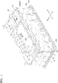
- FIG. 1 is a perspective view illustrating a battery pack according to an embodiment.
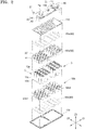
- FIG. 2 is an exploded perspective view illustrating the battery pack in FIG. 1 .
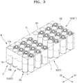
- FIG. 3 is a perspective view illustrating a cell block in FIG. 2 .
- a battery pack may include a plurality of battery cells C, a holder 50 structurally binding the battery cells C together, and tab plates 80 electrically connecting the battery cells C to each other.
- a cooling plate 110 and a circuit board 100 may be sequentially arranged above the tab plates 80.
- the battery cells C may be, e.g., cylindrical battery cells.
- Each battery cell C may include an upper end portion 10a and a lower end portion 10b which form both ends of the battery cell C in the length direction of the battery cell C (e.g., along direction Z3), and a cylindrical lateral surface 10c formed between the upper end portion 10a and the lower end portion 10b.
- the upper end portion 10a and the lower end portion 10b of each battery cell C may form electrodes having different polarities.
- the upper end portion 10a and the lower end portion 10b of each battery cell C may respectively refer to an end portion at an upper position and an end portion at a lower position in a vertical direction (e.g., direction Z3) parallel to the length direction of the battery cell C, and may not be distinguished from each other according to the polarities thereof such as a positive polarity and a negative polarity. That is, the upper end portions 10a of battery cells C adjacent to each other may have the same polarity or different polarities according to the vertical orientations of the battery cells C. Similarly, the lower end portions 10b of battery cells C adjacent to each other may have the same polarity or different polarities according to the vertical orientations of the battery cells C.
- the battery cells C are electrically connected to each other and form a cell block B.
- the cell block B may be a polygonal region that includes a group of battery cells C electrically connected to each other, surrounds the outside of the group of battery cells C, and makes contact with the group of battery cells C.
- the cell block B may be defined as a polyhedral region including an upper surface U facing the upper end portions 10a of the group of battery cells C, a lower surface L facing the lower end portions 10b of the group of battery cells C, and lateral surfaces S facing the lateral surfaces 10c of the group of battery cells C.
- the upper surface U, the lower surface L, and the lateral surfaces S of the cell block B may be defined as surfaces that surround the outside of the group of battery cells C and make contact with the group of battery cells C.
- the cell block B may be a virtual, e.g., imaginary, block with specific defined virtual surfaces that facilitate explanation and definition of elements relative to the group of cells C.
- the cell block B may be defined as a polyhedral region that includes a flat surface making contact with the upper end portions 10a of the group of battery cells C as the upper surface U, a flat surface making contact with the lower end portions 10b of the group of battery cells C as the lower surface L, and flat surfaces making contact with the lateral surfaces 10c of the group of battery cells C as the lateral surfaces S.
- the lateral surfaces 10c of the battery cells C may be formed in a cylindrical shape, e.g., to have curved or wavy surfaces
- the lateral surfaces S of the cell block B are flat surfaces surrounding and being tangent to the lateral surfaces 10c of the battery cells C (e.g., rather than being wavy surfaces connecting and tracing the lateral surfaces 10c of the battery cells C adjacent to each other).
- the cell block B may be formed in a hexahedral shape, and the lateral surfaces S of the cell block B may include a pair of long lateral surfaces S1 and a pair of short lateral surfaces S2 that surround and are tangent to the lateral surfaces 10c of the group of battery cells C.
- Each of the upper surface U and the lower surface L of the cell block B may be a quadrangular surface that has a pair of long sides B1 and a pair of short sides B2 as neighboring sides.
- the long sides B 1 of the cell block B may be relatively long sides along which the upper surface U (or the lower surface L) and the long lateral surfaces S1 of the cell block B having a hexahedral shape are in contact with each other.
- the short sides B2 of the cell block B may be relatively short sides along which the upper surface U (or the lower surface L) and the short lateral surfaces S2 of the cell block B having a hexahedral shape are in contact with each other.
- the lateral surfaces S of the cell block B are not waved surfaces connecting the lateral surfaces 10c of the group of battery cells C to each other, but are flat surfaces surrounding and being tangent to waved surfaces connecting the lateral surfaces 10c of the group of battery cells C to each other. Therefore, the long sides B1 and the short sides B2 along which the lateral surfaces S and the upper surface U (or the lower surface L) are in contact with each other are not waved sides connecting the lateral surfaces 10c of the group of battery cells C but are straight sides surrounding and being tangent to waved sides.
- the battery pack includes a flexible wiring 40.
- the flexible wiring 40 surrounds the cell block B in a direction parallel to the long sides B1 of the cell block B to detect state information from the battery cells C.
- the battery pack may include the holder 50 to structurally bind the battery cells C together.
- the holder 50 may include an array of cell accommodation portions 51 having a cylindrical shape and matching the lateral surfaces 10c of the battery cells C to surround the lateral surfaces 10c of the battery cells C, so the battery cells C may be surrounded by the cell accommodation portions 51 and assembled in place.
- the battery cells C may be placed, e.g., arranged, at staggered positions such that the battery cells C may be inserted between each other, e.g., the battery cells C may be arranged in a honeycomb pattern to have adjacent rows offset with respect to each other, thereby increasing the density of the battery cells C in the battery pack.
- the cell accommodation portions 51 surrounding the battery cells C may also be arranged in the same dense pattern as the battery cells C.
- the holder 50 may include terminal holes 50' to expose at least portions of the upper end portions 10a and the lower end portions 10b of the battery cells C, and allow electrical connection through the upper end portions 10a and the lower end portions 10b.
- the terminal holes 50' may be through-holes penetrating the cell accommodation portions 51 of the holder 50.
- the tab plates 80 may be arranged on, e.g., above, the holder 50 and may be electrically connected to the upper end portions 10a and the lower end portions 10b of the battery cells C that are exposed through the terminal holes 50' of the holder 50.
- the holder 50 may include an upper holder 50a and a lower holder 50b that respectively surround the upper end portions 10a and the lower end portions 10b of the battery cells C, and the lateral surfaces 10c of the battery cells C may be exposed between the upper holder 50a and the lower holder 50b in the length direction of the battery cells C.
- temperature detection positions PT (refer to FIG. 4 ) of the flexible wiring 40 may be formed on exposed portions of the lateral surfaces 10c of the battery cells C.
- the holder 50 may not be integrally formed with respect to the group of battery cells C electrically connected to each other, but may be divided into two parts in a direction Z1 parallel to the long sides B1 of the cell block B.
- the lower holder 50b may include first and second holders 50b1 and 50b2 that are spaced apart from each other in the direction Z1 parallel to the long sides B1 of the cell block B.
- an end extension portion 40e (refer to FIG. 7 ) of the flexible wiring 40 may extend into the cell block B through a gap between the first and second holders 50b1 and 50b2 that are spaced apart from each other, and may form a temperature detection position PT inside the cell block B.
- the lower holder 50b may be divided in the direction Z1 parallel to the long sides B1 of the cell block B according to the number of temperature detection positions PT required to be formed inside the cell block B.
- the upper holder 50a may be formed in one piece with respect to the group of battery cells C electrically connected to each other.
- the group of battery cells C forming the cell block B may be electrically connected to each other through the tab plates 80.
- the tab plates 80 may electrically connect the battery cells C to each other by connecting the upper end portions 10a and the lower end portions 10b of the battery cells C.
- the tab plates 80 may electrically connect the battery cells C in parallel to each other by connecting identical polarities together and may electrically connect the battery cells C in series to each other by connecting opposite polarities together.
- the battery cells C electrically connected to each other by the tab plates 80 may be arranged with the same vertical orientation in a parallel connection direction Z2 such that identical polarities may be connected to each other through the tab plates 80 for parallel connection, and may be arranged with vertically reversed orientations in a series connection direction Z1 such that opposite polarities may be connected together through the tab plates 80 for series connection.
- the parallel connection direction Z2 and the series connection direction Z1 may respectively refer to a direction Z2 parallel to the short sides B2 of the cell block B and a direction Z1 parallel to the long sides B1 of the cell block B.
- the arrangement of the battery cells C in the direction Z2 parallel to the short sides B2 of the cell block B may form parallel connection in which identical polarities are connected to each other through the tab plates 80, and the arrangement of the battery cells C in the direction Z1 parallel to the long sides B1 of the cell block B may form series connection in which different polarities are connected to each other through the tab plates 80.
- the arrangement of the battery cells C forming series connection is set to be longer than the arrangement of the battery cells C forming parallel connection such that the series connection direction Z1 may be parallel to the long sides B1 which are relatively long, and the parallel connection direction Z2 may be parallel to the short sides B2 which are relatively short.
- the parallel connection direction Z2 may be the length direction Z2 of the tab plates 80 in which each tab plate 80 extends
- the series connection direction Z1 may be an arrangement direction Z1 in which the tab plates 80 are arranged.
- the battery cells C may be connected in parallel to each other in the length direction Z2 of the tab plates 80 and may be connected in series to each other in the arrangement direction Z1 in which the tab plates 80 are arranged.
- the tab plates 80 may include upper tab plates 80a connected to the upper end portions 10a of the battery cells C, and lower tab plates 80b connected to the lower end portions 10b of the battery cells C.
- the battery cells C arranged in the parallel connection direction Z2 parallel to the short sides B2 of the cell block B may be connected in parallel to each other through the upper tab plates 80a and the lower tab plates 80b, and the battery cells C arranged in the series connection direction Z1 parallel to the long sides B1 of the cell block B may be connected in series to each other through the upper tab plates 80a and the lower tab plates 80b.
- the upper tab plates 80a and the lower tab plates 80b may be staggered in an alternating pattern in the series connection direction Z1 such that the battery cells C arranged in the series connection direction Z1 may be connected in series to each other through the upper tab plates 80a and the lower tab plates 80b.
- the flexible wiring 40 may extend to surround the cell block B in the series connection direction Z1 parallel to the long sides B1 and may form, e.g., include, voltage detection positions PV (refer to FIG. 4 ) while extending across the tab plates 80 arranged in the series connection direction Z1.
- the circuit board 100 may be placed on the tab plates 80.
- the circuit board 100 may collect state information from the battery cells C and control charge and discharge operations of the battery cells C based on the collected state information.
- the circuit board 100 may detect malfunctions of the battery cells C, e.g., overheating, overcharging, or overdischarging, and may take protective measures to prevent accidents, e.g., explosions or fires, and may stop charge and discharge operations of the battery cells C by using a switch device 90 provided on a charge-discharge path.
- the flexible wiring 40 may be connected to the circuit board 100.
- An end portion of the flexible wiring 40 may be connected to the circuit board 100 to form a connection position PB, and voltage and temperature information collected through the flexible wiring 40 may be transmitted to the circuit board 100 via the connection position PB.
- the cooling plate 110 may be arranged between the circuit board 100 and the tab plates 80.
- the cooling plate 110 is arranged between the circuit board 100 and the tab plates 80, and thus, state information regarding the battery cells C may not be transmitted directly from the tab plates 80 to the circuit board 100.
- state information regarding the battery cells C may be transmitted to the circuit board 100 through the flexible wiring 40, which extends around the cell block B in opposite directions to surround the cell block B.
- the cooling plate 110 may be arranged between the tab plates 80 and the circuit board 100 to cool the circuit board 100 together with the battery cells C connected to the tab plates 80.
- the cooling plate 110 may cool circuit elements arranged on the circuit board 100 and the switch device 90 connected to the circuit board 100, and may cool the battery cells C through the tab plates 80.
- the cooling plate 110 may cool the switch device 90, which is connected to the circuit board 100 and placed on the charge-discharge path to connect and disconnect the charge and discharge path.
- the switch device 90 may be provided between the circuit board 100 and an external terminal E2.
- a pair of external terminals E1 and E2 may be formed and may be respectively connected to the circuit board 100 and the switch device 90.
- reference numeral 130 in FIG. 2 denotes an insulating frame for insulating the tab plates 80 (the lower tab plates 80b).
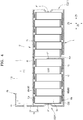
- FIG. 4 is a view schematically illustrating an arrangement of the flexible wiring 40.
- FIGS. 5 to 7 are perspective views illustrating the battery pack in different directions according to embodiments.
- FIG. 8 illustrates a structure of the flexible wiring 40.
- the battery pack includes the flexible wiring 40 that surrounds the cell block B in the direction Z1 parallel to the long sides B1 of the cell block B for detecting state information about the battery cells C, e.g., the flexible wiring 40 may extend along surfaces U and L along the direction Z1 to surround the cell block B.
- the flexible wiring 40 may extend to surround the cell block B in the direction Z1 parallel to the long sides B1 of the cell block B to efficiently collect state information about the group of battery cells C forming the cell block B.
- the flexible wiring 40 extends to surround the cell block B in the direction Z1 parallel to the long sides B1 of the cell block B such that the flexible wiring 40 may extend across a relatively large number of battery cells C and the number of battery cells C, which are monitorable using the flexible wiring 40 wound once around the cell block B, may be increased.
- the flexible wiring 40 were to extend around the cell block B in the direction Z2 parallel to the short sides B2 of the cell block B (rather than the direction Z1), the flexible wiring 40 would extend across a relatively small number of battery cells C, thereby limiting the number of monitorable battery cells C via a single flexible wiring 40 and requiring additional flexible wiring 40 to collect state information from a same number of battery cells C.
- the flexible wiring 40 may include a first flexible wire 41 surrounding the cell block B in a forward direction parallel to the long sides B 1 of the cell block B, and a second flexible wire 42 surrounding the cell block B in a reverse direction parallel to the long sides B 1 of the cell block B.
- the forward direction and the reverse direction may respectively refer to clockwise and counterclockwise directions which are parallel to the long sides B1 of the cell block B.
- the first and second flexible wires 41 and 42 may extend in the direction Z1 parallel to the long sides B1 of the cell block B, such that when viewed toward lateral surface S1 of the cell block B (into the page of FIGS. 3 and 4 ), the first and second flexible wires 41 and 42 surround the cell block B respectively in the clockwise and counterclockwise directions.
- the first flexible wire 41 may surround the cell block B in the forward direction (e.g., extend right in FIG. 4 ) parallel to the long sides B1 of the cell block B, while extending across the upper surface U and a first lateral surface S21 of the cell block B, and extending to a side ( e.g. a first side) of the lower surface L of the cell block B.
- the second flexible wire 42 may surround the cell block B in the reverse direction parallel to the long sides B1 of the cell block B, while extending across a second lateral surface S22 of the cell block B to the other side ( e.g. a second side) of the lower surface L of the cell block B.
- the first and second lateral surfaces S21 and S22 of the cell block B, across which the first and second flexible wires 41 and 42 extend may be lateral surfaces S which face each other in the direction Z1 parallel to the long sides B1.
- the first and second flexible wires 41 and 42 may extend across the upper and lower surfaces U and L of the cell block B, which are opposite each other, and across the first and second lateral surfaces S21 and S22 of the cell block B, which are opposite each other, such that state information may be detected through the first and second flexible wires 41 and 42.
- the first and second flexible wires 41 and 42 may form a plurality of voltage detection positions PV along extension paths thereof.
- the first and second flexible wires 41 and 42 may form, e.g., define, voltage detection positions PV while making conductive contact with the tab plates 80 that electrically connect the battery cells C to each other.
- the tab plates 80 electrically connected to the upper end portions 10a and the lower end portions 10b of the battery cells C may have substantially the same potentials as the electrodes of the battery cells C, and thus, voltage information about the battery cells C may be detected through the flexible wiring 40, which are in conductive contact with the tab plates 80.
- a portion of the first flexible wire 41 (on the upper surface U) may extend between the cooling plate 110 and the upper tab plate 80a, and a portion of the second flexible wire 42 (on the lower surface L) may extend between the insulating plate 130 and the lower tab plate 80b.
- the first flexible wire 41 may make conductive contact with the upper tab plates 80a connected to the upper end portions 10a of the battery cells C to form voltage detection positions PV, and while extending across one side (e.g. a first side) of the lower surface L of the cell block B, the first flexible wire 41 may make conductive contact with the lower tab plates 80b connected to the lower end portions 10b of the battery cells C to form voltage detection positions PV.
- the second flexible wire 42 may make conductive contact with the lower tab plates 80b connected to the lower end portions 10b of the battery cells C to form voltage detection positions PV.
- the first flexible wire 41 may be arranged on one side (e.g. a first side) of the lower surface L of the cell block B (e.g., right side of FIG. 4 ), and the second flexible wire 42 may be arranged on the other side ( e.g. a second side) of the lower surface L of the cell block B (e.g., left side of FIG. 4 ), such that the lower surface L of the cell block B may be divided into two sides that do not overlap each other, and voltage information may be collected from the two sides respectively through the first and second flexible wires 41 and 42.
- the first and second flexible wires 41 and 42 are for detecting state information from the battery cells C while extending across the cell block B, and since the combination of the first and second flexible wires 41 and 42 extends around the cell block B, state information may be detected from the group of battery cells C electrically connected to each other.
- the first and second flexible wires 41 and 42 may not be arranged in an overlapping manner.
- the first and second flexible wires 41 and 42 may have a non-overlapping relationship on the lower surface L in a plan view, e.g., the first and second flexible wires 41 and 42 may define a single loop surrounding the cell block B without overlapping portions.
- the sides of the lower surface L of the cell block B on which the first and second flexible wires 41 and 42 are respectively arranged may correspond to the bottom surfaces of the first and second holders 50b1 and 50b2, which are separated from each other.
- the flexible wiring 40 may extend to surround the cell block B in the series connection direction Z1 parallel to the long sides B1 and may form the voltage detection positions PV together with the tab plates 80 while extending across the tab plates 80 arranged in the series connection direction Z1.
- the series connection direction Z1 may refer to the direction Z1 in which the tab plates 80 are arranged, and the flexible wiring 40 may extend across the tab plates 80 arranged in the series connection direction Z1 to collect voltage information via the tab plates 80.
- the flexible wiring 40 may be used to detect temperature information together with voltage information.
- the flexible wiring 40 may form voltage detection positions PV for detecting voltage information about the battery cells C while making conductive contact with the tab plates 80 arranged on the upper surface U and the lower surface L of the cell block B, and may form temperature detection positions PT for detecting temperature information about the battery cells C while extending across the lateral surfaces S of the cell block B and making thermal contact with the lateral surfaces 10c of the battery cells C.
- the first and second flexible wires 41 and 42 may surround the cell block B in the forward and reverse directions parallel to the long sides B1 of the cell block B while extending across the first and second lateral surfaces S21 and S22 of the cell block B that are opposite each other in the direction Z1 parallel to the long sides B1, and may form temperature detection positions PT on the lateral surfaces 10c of the battery cells C to detect temperature information.
- the lateral surfaces 10c of the battery cells C may be exposed between the upper holder 50a and the lower holder 50b that surround the battery cells C. That is, the temperature detection positions PT of the flexible wiring 40 may be formed, e.g., directly, on the exposed lateral surfaces 10c of the battery cells C.
- the flexible wiring 40 may form the temperature detection positions PT on the lateral surfaces 10c of the battery cells C, and bent portions R may be formed in front of and behind each of the temperature detection positions PT in the length direction of the flexible wiring 40.
- the bent portions R of the flexible wiring 40 may be structures protruding toward the lateral surfaces 10c of the battery cells C and making tight contact with the lateral surfaces 10c of the battery cells C to form the temperature detection positions PT, and may be structures for effectively bringing the flexible wiring 40 (for example, refer to thermistors 40b shown in FIG. 8 ) into, e.g., direct, contact with the lateral surfaces 10c of the battery cells C.
- each bent portion R of the flexible wiring 40 may extend between respective upper and lower holders 50a and 50b, e.g., in an approximate U-shape, on an exposed portion of the battery cell C between the upper holder 50a and the lower holder 50b to define the temperature detection positions PT, e.g., each bent portion R may protrude from a linear portion of the flexible wiring 40 on the holder 50 toward an exposed portion of the battery cell C between the upper holder 50a and the lower holder 50b.
- the first and second flexible wires 41 and 42 may form temperature detection positions PT on the first and second lateral surfaces S21 and S22 of the cell block B, and heat may be relatively easily dissipated from the first and second lateral surfaces S21 and S22 of the cell block B because the first and second lateral surfaces S21 and S22 of the cell block B are exposed to the outside.
- a temperature detection position PT may be formed on an inner portion of the cell block B from which heat is relatively poorly dissipated because the inner portion is not exposed to the outside.
- the second flexible wire 42 may extend on the lower surface L across the second lateral surface S22 of the cell block B while extending along the cell block B in the reverse direction parallel to the long sides B1, and an end extension portion 40e of the second flexible wire 42 may enter the inside of the cell block B, e.g., may extend upwards in the Z3 direction between two adjacent interior battery cells C of the cell block B to include a temperature detection position PT on the lateral surface 10c of an internal battery cell C.
- the end extension portion 40e of the second flexible wire 42 may enter the inside of the cell block B through the gap which is formed in the lower surface L of the cell block B between the first and second holders 50b1 and 50b2, and may form a temperature detection position PT on the lateral surface 10c of an internal battery cell C.
- temperature detection positions PT are formed on the first and second lateral surfaces S21 and S22 of the cell block B, which are outer lateral surfaces S of the cell block B, and on an inner portion of the cell block B from which heat is relatively poorly dissipated, such that overheating of the cell block B may be detected without failure to take measures against overheating.
- the flexible wiring 40 may have, e.g., exhibit, flexibility to surround the cell block B in the forward and reverse directions parallel to the long sides B1 of the cell block B.
- the flexible wiring 40 may include sensing structures at the voltage detection positions PV and the temperature detection positions PT of the battery cells C, and voltage detection lines and temperature detection lines connected to the voltage detection positions PV and the temperature detection positions PT.
- the flexible wiring 40 may be a flexible circuit board but is not limited thereto.
- the flexible wiring 40 may form voltage detection positions PV and temperature detection positions PT at different locations in the length direction Z1 of the flexible wiring 40.
- the flexible wiring 40 may form voltage detection positions PV on the upper surface U and the lower surface L of the cell block B, and temperature detection positions PT on the first and second lateral surfaces S21 and S22 of the cell block B, i.e., the voltage detection positions PV and temperature detection positions PT are at different locations in the length direction Z1 of the flexible wiring 40.
- the flexible wiring 40 may form a plurality of voltage detection positions PV at different locations in the length direction Z1 of the flexible wiring 40, and similarly, the flexible wiring 40 may form a plurality of temperature detection positions PT at different positions in the length direction of the flexible wiring 40.
- the flexible wiring 40 may include conductive pads 40a which are exposed through an insulating film 40c of the flexible wiring 40 at the voltage detection positions PV.
- the conductive pads 40a may be connected to the voltage detection lines covered with the insulating film 40c of the flexible wiring 40, and the voltage detection lines may be connected to the circuit board 100 through a connector CN formed at an end portion of the flexible wiring 40.
- the flexible wiring 40 may include thermistors 40b exposed through the insulating film 40c of the flexible wiring 40 at the temperature detection positions PT.
- the thermistors 40b may be chip-type thermistors, which are directly mounted on the flexible wiring 40 by a solder mounting method in which terminals of the thermistors 40b are fitted to the flexible wiring 40 and solder is applied thereto.
- the thermistors 40b provided as chip-type thermistors are directly mounted on the flexible wiring 40, additional leads for connecting the thermistors 40b to the flexible wiring 40 are not required.
- the thermistors 40b may be connected to the temperature detection lines covered with the insulating film 40c of the flexible wiring 40, and the temperature detection lines may be connected to the circuit board 100 through the connector CN formed on the end portion of the flexible wiring 40.
- the flexible wiring 40 may be connected to the circuit board 100.
- the flexible wiring 40 may include the first and second flexible wires 41 and 42, and connection positions PB of the first and second flexible wires 41 and 42 may be formed on the same side of the circuit board 100.
- the circuit board 100 may include a relatively long side 101 and a relatively short side 102, and the connection positions PB of the first and second flexible wires 41 and 42 may be formed on the same short side 102.
- the first and second flexible wires 41 and 42 may extend to surround the cell block B in the direction Z1 parallel to the long sides B1 of the cell block B, and to this end, the first and second flexible wires 41 and 42 may surround the cell block B from a short side B2 of the cell block B.
- the connection positions PB may be formed on the short side 102 of the circuit board 100, which is parallel to the short sides B2 of the cell block B.
- the first and second flexible wires 41 and 42 may extend in the direction Z1 parallel to the long sides B 1 of the cell block B from the connection positions PB with the circuit board 100.
- the connection positions PB of the first and second flexible wires 41 and 42 may be respectively formed on opposite short sides 102 of the circuit board 100.
- connection positions PB of the first and second flexible wires 41 and 42 are formed on the same side of the circuit board 100, the connection positions PB of the first and second flexible wires 41 and 42 may not be the same position or may not overlap each other.
- the connection positions PB of the first and second flexible wires 41 and 42 may be offset along the short side 102 of the circuit board 100. Therefore, electrical and physical interference between the first and second flexible wires 41 and 42 may be prevented.
- the first and second flexible wires 41 and 42 may not surround the cell block B in such a manner that the first and second flexible wires 41 and 42 extend in the forward and reverse directions, which are parallel to the long sides B 1 of the cell block B, immediately from the connection positions PB of the circuit board 100.
- the first and second flexible wires 41 and 42 may extend in the same direction from the connection positions PB of the circuit board 100 toward an edge of the cooling plate 110, and then the first and second flexible wires 41 and 42 may extend from the edge of the cooling plate 110 in the forward and reverse directions to surround the cell block B.
- the first flexible wire 41 may extend in parallel with the second flexible wire 42 from the connection positions PB of the circuit board 100, then along the cooling plate 110 to bypass the cooling plate 110, and then between the cooling plate 110 and the cell block B to form the voltage detection positions PV on the upper surface U of the cell block B.
- the expression "the first and second flexible wires 41 and 42 surround the cell block B in the forward and reverse directions which are parallel to the long sides B1" is for describing the directions in which the first and second flexible wires 41 and 42 surround the cell block B, but is not for describing the direction in which the first and second flexible wires 41 and 42 extend in parallel to each other from the connection positions PB of the circuit board 100 before the first and second flexible wires 41 and 42 surround the cell block B or is not for describing the direction in which the first flexible wire 41 surrounds the cooling plate 110.
- the first and second flexible wires 41 and 42 may extend in the same direction from the connection positions PB of the circuit board 100.
- the direction is not a direction in which the first and second flexible wires 41 and 42 surround the cell block B, and the directions in which the first and second flexible wires 41 and 42 surround the cell block B are the forward and reverse directions, which are opposite each other.
- one or more embodiments include a battery pack having an improved structure for collecting state information from a plurality of battery cells. That is, as described above, according to the one or more of the above embodiments, state information may be collected from the battery cells C through the flexible wiring 40 surrounding the cell block B in the forward and reverse directions to detect temperature information about the battery cells C and also voltage information about the battery cells C.
- cooling efficiency may be improved due to the cooling plate 110 provided between the cell block B and the circuit board 100.
- state information about the battery cells C may be easily collected through the flexible wiring 40 which connects the cell block B to the circuit board 100 while bypassing the cooling plate 110.
Landscapes
- Chemical & Material Sciences (AREA)
- Chemical Kinetics & Catalysis (AREA)
- Electrochemistry (AREA)
- General Chemical & Material Sciences (AREA)
- Engineering & Computer Science (AREA)
- Manufacturing & Machinery (AREA)
- Microelectronics & Electronic Packaging (AREA)
- Connection Of Batteries Or Terminals (AREA)
- Battery Mounting, Suspending (AREA)
Abstract
A battery pack includes a cell block including battery cells electrically connected to each other, the cell block having a pair of long sides and a pair of short sides which surround lateral surfaces of the battery cells and are tangent to the lateral surfaces of the battery cells, and a flexible wiring surrounding the cell block in a direction parallel to the pair of long sides of the cell block, the flexible wiring including sensors to detect state information from the battery cells.
Description
- One or more embodiments relate to a battery pack.
- In general, secondary batteries refer to batteries that can be charged and recharged unlike non-rechargeable primary batteries. Secondary batteries are used as energy sources of devices, e.g., mobile devices, electric vehicles, hybrid vehicles, electric bicycles, or uninterruptible power supplies. Secondary batteries may be used individually or in modules (packs), e.g., each module may include a plurality of secondary batteries connected as one unit, according to the types of external devices using the secondary batteries.
- Unlike small mobile devices, e.g., cellular phones, that are operable for a certain period of time using a single battery, large devices, e.g., electric vehicles or hybrid vehicles, have long operation times and consume large amounts of electricity, and therefore, implement battery modules (packs) including a plurality of batteries (battery cells) to address larger power and capacity requirements. The output voltages or currents of battery modules may be increased by adjusting the number of batteries included in each battery module.
- According to one or more embodiments, a battery pack includes a cell block with battery cells electrically connected to each other, the cell block having a pair of long sides and a pair of short sides which surround lateral surfaces of the battery cells and are tangent to the lateral surfaces of the battery cells, and a flexible wiring surrounding the cell block in a direction parallel to the pair of long sides of the cell block, the flexible wiring including sensors to detect state information from the battery cells.
- For example, the flexible wiring may surround opposite upper and lower surfaces and opposite first and second lateral surfaces of the cell block and may be configured to collect state information from the group of battery cells.
- For example, the flexible wiring may surround the opposite upper and lower surfaces and the opposite first and second lateral surfaces of the cell block in opposite directions parallel to the pair of long sides of the cell block.
- For example, the flexible wiring may form (e.g. include) voltage detection positions on the upper and lower surfaces of the cell block, and temperature detection positions on the first and second lateral surfaces of the cell block.
- For example, the flexible wiring may include an end extension portion extending along the lower surface of the cell block and into the cell block, and the end extension portion may form (e.g. include) a temperature detection position inside the cell block.
- For example, the battery pack may further include a holder into which the group of battery cells are inserted, the holder including a first holder and a second holder which are separate from each other in the direction parallel to the pair of long sides of the cell block, wherein the end extension portion may extend into the cell block through a gap between the first and second holders.
- For example, the flexible wiring may make, at voltage detection positions, conductive contact with a tab plate which electrically connects the group of battery cells to each other, and the flexible wiring may make, at temperature detection positions, thermal contact with the lateral surfaces of the group of battery cells.
- For example, the battery pack may further include a plurality of tab plates electrically connecting the group of battery cells to each other and arranged in the direction parallel (e.g. extending in parallel) to the pair of long sides of the cell block, wherein the flexible wiring may extend across the plurality of tab plates and forms voltage detection positions while making conductive contact with the plurality of tab plates.
- For example, the flexible wiring may include bent portions which are formed in front of and behind a temperature detection position in a length direction of the flexible wiring. For example, the flexible wiring may include bent portions at temperature detection positions along a length direction of the flexible wiring.
- For example, the battery pack may further include a circuit board connected to the flexible wiring, and a cooling plate between the circuit board and the cell block, wherein the flexible wiring may extend from a connection position with the circuit board along the cooling plate (e.g. while surrounding the cooling plate) to bypass the cooling plate, and may extend between the cooling plate and the cell block to form voltage detection positions.
- For example, the flexible wiring may include a first flexible wire extending along (e.g. surrounding) the cell block in a forward direction parallel to the pair of long sides of the cell block, and a second flexible wire extending along (e.g. surrounding) the cell block in a reverse direction parallel to the pair of long sides of the cell block.
- For example, the first flexible wire may extend along (e.g. surround) the cell block in a clockwise direction parallel to the pair of long sides of the cell block, and the second flexible wire may extend along (e.g. surround) the cell block in a counterclockwise direction parallel to the pair of long sides of the cell block.
- For example, the first flexible wire may extend along (e.g. surround) an upper surface and a first lateral surface of the cell block to a side (e.g. a first side) of a lower surface of the cell block, and the second flexible wire may extend (e.g. surround) along a second lateral surface of the cell block to the other side (e.g. a second side) of the lower surface of the cell block.
- For example, the battery pack may further include a cooling plate on the cell block, wherein the first flexible wire may extend between the cooling plate and the upper surface of the cell block.
- For example, the battery pack may further include a holder into which the group of battery cells are inserted, the holder including a first holder and a second holder which are separate from each other in the direction parallel to the pair of long sides of the cell block, and the side (e.g. the first side) and the other side (e.g. the second side) of the lower surface of the cell block may respectively correspond to lower surfaces of the second and first holders.
- For example, the second flexible wire may extend along the other side (e.g. the second side) of the lower surface of the cell block into the cell block.
- For example, the flexible wiring may form (e.g. include) voltage detection positions together with a plurality of tab plates arranged in a length direction of the flexible wiring.
- For example, the flexible wiring may form (e.g. include) voltage detection positions and temperature detection positions that are spaced apart from each other in a length direction of the flexible wiring.
- For example, wherein the flexible wiring may include thermistors mounted on the flexible wiring at temperature detection positions.
- At least some of the above and other features of the invention are set out in the claims.
- Features will become apparent to those of skill in the art by describing in detail embodiments with reference to the attached drawings, in which:
-
FIG. 1 is a perspective view illustrating a battery pack according to an embodiment; -
FIG. 2 is an exploded perspective view illustrating the battery pack inFIG. 1 ; -
FIG. 3 is a perspective view illustrating a cell block inFIG. 2 ; -
FIG. 4 is a view schematically illustrating an arrangement of flexible wiring; -
FIGS. 5 to 7 are perspective views illustrating the battery pack in different directions according to embodiments; and -
FIG. 8 is a view illustrating a structure of the flexible wiring. - Example embodiments will now be described more fully hereinafter with reference to the accompanying drawings; however, they may be embodied in different forms and should not be construed as limited to the embodiments set forth herein. Rather, these embodiments are provided so that this disclosure will be thorough and complete, and will fully convey implementations to those skilled in the art.
- In the drawing figures, the dimensions of layers and regions may be exaggerated for clarity of illustration. It will also be understood that when a layer or element is referred to as being "on" another layer or substrate, it can be directly on the other layer or substrate, or intervening layers may also be present. In addition, it will also be understood that when a layer is referred to as being "between" two layers, it can be the only layer between the two layers, or one or more intervening layers may also be present. Like reference numerals refer to like elements throughout.
- As used herein, the term "and/or" includes any and all combinations of one or more of the associated listed items. Throughout the disclosure, the expression "at least one of a, b or c" indicates only a, only b, only c, both a and b, both a and c, both b and c, all of a, b, and c, or variations thereof.
- A battery pack will now be described according to embodiments with reference to the accompanying drawings.
-
FIG. 1 is a perspective view illustrating a battery pack according to an embodiment.FIG. 2 is an exploded perspective view illustrating the battery pack inFIG. 1 .FIG. 3 is a perspective view illustrating a cell block inFIG. 2 . - Referring to
FIGS. 1-2 , according to an embodiment, a battery pack may include a plurality of battery cells C, aholder 50 structurally binding the battery cells C together, andtab plates 80 electrically connecting the battery cells C to each other. Acooling plate 110 and acircuit board 100 may be sequentially arranged above thetab plates 80. - In detail, the battery cells C may be, e.g., cylindrical battery cells. Each battery cell C may include an
upper end portion 10a and alower end portion 10b which form both ends of the battery cell C in the length direction of the battery cell C (e.g., along direction Z3), and a cylindricallateral surface 10c formed between theupper end portion 10a and thelower end portion 10b. Theupper end portion 10a and thelower end portion 10b of each battery cell C may form electrodes having different polarities. Throughout the present specification, theupper end portion 10a and thelower end portion 10b of each battery cell C may respectively refer to an end portion at an upper position and an end portion at a lower position in a vertical direction (e.g., direction Z3) parallel to the length direction of the battery cell C, and may not be distinguished from each other according to the polarities thereof such as a positive polarity and a negative polarity. That is, theupper end portions 10a of battery cells C adjacent to each other may have the same polarity or different polarities according to the vertical orientations of the battery cells C. Similarly, thelower end portions 10b of battery cells C adjacent to each other may have the same polarity or different polarities according to the vertical orientations of the battery cells C. - Referring to
FIG. 3 , the battery cells C are electrically connected to each other and form a cell block B. The cell block B may be a polygonal region that includes a group of battery cells C electrically connected to each other, surrounds the outside of the group of battery cells C, and makes contact with the group of battery cells C. For example, the cell block B may be defined as a polyhedral region including an upper surface U facing theupper end portions 10a of the group of battery cells C, a lower surface L facing thelower end portions 10b of the group of battery cells C, and lateral surfaces S facing thelateral surfaces 10c of the group of battery cells C. In this case, the upper surface U, the lower surface L, and the lateral surfaces S of the cell block B may be defined as surfaces that surround the outside of the group of battery cells C and make contact with the group of battery cells C. The cell block B may be a virtual, e.g., imaginary, block with specific defined virtual surfaces that facilitate explanation and definition of elements relative to the group of cells C. - For example, the cell block B may be defined as a polyhedral region that includes a flat surface making contact with the
upper end portions 10a of the group of battery cells C as the upper surface U, a flat surface making contact with thelower end portions 10b of the group of battery cells C as the lower surface L, and flat surfaces making contact with thelateral surfaces 10c of the group of battery cells C as the lateral surfaces S. For example, even though thelateral surfaces 10c of the battery cells C may be formed in a cylindrical shape, e.g., to have curved or wavy surfaces, the lateral surfaces S of the cell block B are flat surfaces surrounding and being tangent to thelateral surfaces 10c of the battery cells C (e.g., rather than being wavy surfaces connecting and tracing thelateral surfaces 10c of the battery cells C adjacent to each other). In an embodiment, the cell block B may be formed in a hexahedral shape, and the lateral surfaces S of the cell block B may include a pair of long lateral surfaces S1 and a pair of short lateral surfaces S2 that surround and are tangent to thelateral surfaces 10c of the group of battery cells C. - Each of the upper surface U and the lower surface L of the cell block B may be a quadrangular surface that has a pair of long sides B1 and a pair of short sides B2 as neighboring sides. For example, the long sides B 1 of the cell block B may be relatively long sides along which the upper surface U (or the lower surface L) and the long lateral surfaces S1 of the cell block B having a hexahedral shape are in contact with each other. In addition, the short sides B2 of the cell block B may be relatively short sides along which the upper surface U (or the lower surface L) and the short lateral surfaces S2 of the cell block B having a hexahedral shape are in contact with each other. As described above, the lateral surfaces S of the cell block B are not waved surfaces connecting the lateral surfaces 10c of the group of battery cells C to each other, but are flat surfaces surrounding and being tangent to waved surfaces connecting the lateral surfaces 10c of the group of battery cells C to each other. Therefore, the long sides B1 and the short sides B2 along which the lateral surfaces S and the upper surface U (or the lower surface L) are in contact with each other are not waved sides connecting the lateral surfaces 10c of the group of battery cells C but are straight sides surrounding and being tangent to waved sides.
- Referring back to
FIG. 2 , according to an embodiment, the battery pack includes aflexible wiring 40. As will be described in more detail below with reference toFIG. 4 , theflexible wiring 40 surrounds the cell block B in a direction parallel to the long sides B1 of the cell block B to detect state information from the battery cells C. - As illustrated in
FIG. 2 , the battery pack may include theholder 50 to structurally bind the battery cells C together. Theholder 50 may include an array ofcell accommodation portions 51 having a cylindrical shape and matching the lateral surfaces 10c of the battery cells C to surround the lateral surfaces 10c of the battery cells C, so the battery cells C may be surrounded by thecell accommodation portions 51 and assembled in place. The battery cells C may be placed, e.g., arranged, at staggered positions such that the battery cells C may be inserted between each other, e.g., the battery cells C may be arranged in a honeycomb pattern to have adjacent rows offset with respect to each other, thereby increasing the density of the battery cells C in the battery pack. According to the dense arrangement of the battery cells C, thecell accommodation portions 51 surrounding the battery cells C may also be arranged in the same dense pattern as the battery cells C. - The
holder 50 may include terminal holes 50' to expose at least portions of theupper end portions 10a and thelower end portions 10b of the battery cells C, and allow electrical connection through theupper end portions 10a and thelower end portions 10b. For example, the terminal holes 50' may be through-holes penetrating thecell accommodation portions 51 of theholder 50. For example, thetab plates 80 may be arranged on, e.g., above, theholder 50 and may be electrically connected to theupper end portions 10a and thelower end portions 10b of the battery cells C that are exposed through the terminal holes 50' of theholder 50. - The
holder 50 may include anupper holder 50a and alower holder 50b that respectively surround theupper end portions 10a and thelower end portions 10b of the battery cells C, and the lateral surfaces 10c of the battery cells C may be exposed between theupper holder 50a and thelower holder 50b in the length direction of the battery cells C. As will be described in more detail below, temperature detection positions PT (refer toFIG. 4 ) of theflexible wiring 40 may be formed on exposed portions of the lateral surfaces 10c of the battery cells C. - The
holder 50 may not be integrally formed with respect to the group of battery cells C electrically connected to each other, but may be divided into two parts in a direction Z1 parallel to the long sides B1 of the cell block B. For example, thelower holder 50b may include first and second holders 50b1 and 50b2 that are spaced apart from each other in the direction Z1 parallel to the long sides B1 of the cell block B. As described below, anend extension portion 40e (refer toFIG. 7 ) of theflexible wiring 40 may extend into the cell block B through a gap between the first and second holders 50b1 and 50b2 that are spaced apart from each other, and may form a temperature detection position PT inside the cell block B. In another embodiment, thelower holder 50b may be divided in the direction Z1 parallel to the long sides B1 of the cell block B according to the number of temperature detection positions PT required to be formed inside the cell block B. Furthermore, according to an embodiment, unlike thelower holder 50b, theupper holder 50a may be formed in one piece with respect to the group of battery cells C electrically connected to each other. - The group of battery cells C forming the cell block B may be electrically connected to each other through the
tab plates 80. Thetab plates 80 may electrically connect the battery cells C to each other by connecting theupper end portions 10a and thelower end portions 10b of the battery cells C. In this case, thetab plates 80 may electrically connect the battery cells C in parallel to each other by connecting identical polarities together and may electrically connect the battery cells C in series to each other by connecting opposite polarities together. - The battery cells C electrically connected to each other by the
tab plates 80 may be arranged with the same vertical orientation in a parallel connection direction Z2 such that identical polarities may be connected to each other through thetab plates 80 for parallel connection, and may be arranged with vertically reversed orientations in a series connection direction Z1 such that opposite polarities may be connected together through thetab plates 80 for series connection. Here, the parallel connection direction Z2 and the series connection direction Z1 may respectively refer to a direction Z2 parallel to the short sides B2 of the cell block B and a direction Z1 parallel to the long sides B1 of the cell block B. In an embodiment, the arrangement of the battery cells C in the direction Z2 parallel to the short sides B2 of the cell block B may form parallel connection in which identical polarities are connected to each other through thetab plates 80, and the arrangement of the battery cells C in the direction Z1 parallel to the long sides B1 of the cell block B may form series connection in which different polarities are connected to each other through thetab plates 80. In this case, the arrangement of the battery cells C forming series connection is set to be longer than the arrangement of the battery cells C forming parallel connection such that the series connection direction Z1 may be parallel to the long sides B1 which are relatively long, and the parallel connection direction Z2 may be parallel to the short sides B2 which are relatively short. - In an embodiment, the parallel connection direction Z2 may be the length direction Z2 of the
tab plates 80 in which eachtab plate 80 extends, and the series connection direction Z1 may be an arrangement direction Z1 in which thetab plates 80 are arranged. The battery cells C may be connected in parallel to each other in the length direction Z2 of thetab plates 80 and may be connected in series to each other in the arrangement direction Z1 in which thetab plates 80 are arranged. - The
tab plates 80 may includeupper tab plates 80a connected to theupper end portions 10a of the battery cells C, andlower tab plates 80b connected to thelower end portions 10b of the battery cells C. The battery cells C arranged in the parallel connection direction Z2 parallel to the short sides B2 of the cell block B may be connected in parallel to each other through theupper tab plates 80a and thelower tab plates 80b, and the battery cells C arranged in the series connection direction Z1 parallel to the long sides B1 of the cell block B may be connected in series to each other through theupper tab plates 80a and thelower tab plates 80b. In this case, theupper tab plates 80a and thelower tab plates 80b may be staggered in an alternating pattern in the series connection direction Z1 such that the battery cells C arranged in the series connection direction Z1 may be connected in series to each other through theupper tab plates 80a and thelower tab plates 80b. As described later, according to an embodiment, theflexible wiring 40 may extend to surround the cell block B in the series connection direction Z1 parallel to the long sides B1 and may form, e.g., include, voltage detection positions PV (refer toFIG. 4 ) while extending across thetab plates 80 arranged in the series connection direction Z1. - The
circuit board 100 may be placed on thetab plates 80. Thecircuit board 100 may collect state information from the battery cells C and control charge and discharge operations of the battery cells C based on the collected state information. For example, thecircuit board 100 may detect malfunctions of the battery cells C, e.g., overheating, overcharging, or overdischarging, and may take protective measures to prevent accidents, e.g., explosions or fires, and may stop charge and discharge operations of the battery cells C by using aswitch device 90 provided on a charge-discharge path. - The
flexible wiring 40 may be connected to thecircuit board 100. An end portion of theflexible wiring 40 may be connected to thecircuit board 100 to form a connection position PB, and voltage and temperature information collected through theflexible wiring 40 may be transmitted to thecircuit board 100 via the connection position PB. - The
cooling plate 110 may be arranged between thecircuit board 100 and thetab plates 80. In an embodiment, thecooling plate 110 is arranged between thecircuit board 100 and thetab plates 80, and thus, state information regarding the battery cells C may not be transmitted directly from thetab plates 80 to thecircuit board 100. Thus, in an embodiment, state information regarding the battery cells C may be transmitted to thecircuit board 100 through theflexible wiring 40, which extends around the cell block B in opposite directions to surround the cell block B. - The
cooling plate 110 may be arranged between thetab plates 80 and thecircuit board 100 to cool thecircuit board 100 together with the battery cells C connected to thetab plates 80. For example, thecooling plate 110 may cool circuit elements arranged on thecircuit board 100 and theswitch device 90 connected to thecircuit board 100, and may cool the battery cells C through thetab plates 80. For example, thecooling plate 110 may cool theswitch device 90, which is connected to thecircuit board 100 and placed on the charge-discharge path to connect and disconnect the charge and discharge path. In addition, theswitch device 90 may be provided between thecircuit board 100 and an external terminal E2. A pair of external terminals E1 and E2 may be formed and may be respectively connected to thecircuit board 100 and theswitch device 90. In addition,reference numeral 130 inFIG. 2 denotes an insulating frame for insulating the tab plates 80 (thelower tab plates 80b). -
FIG. 4 is a view schematically illustrating an arrangement of theflexible wiring 40.FIGS. 5 to 7 are perspective views illustrating the battery pack in different directions according to embodiments.FIG. 8 illustrates a structure of theflexible wiring 40. - Referring to
FIGS. 4 to 7 , according to embodiments, the battery pack includes theflexible wiring 40 that surrounds the cell block B in the direction Z1 parallel to the long sides B1 of the cell block B for detecting state information about the battery cells C, e.g., theflexible wiring 40 may extend along surfaces U and L along the direction Z1 to surround the cell block B. Theflexible wiring 40 may extend to surround the cell block B in the direction Z1 parallel to the long sides B1 of the cell block B to efficiently collect state information about the group of battery cells C forming the cell block B. Theflexible wiring 40 extends to surround the cell block B in the direction Z1 parallel to the long sides B1 of the cell block B such that theflexible wiring 40 may extend across a relatively large number of battery cells C and the number of battery cells C, which are monitorable using theflexible wiring 40 wound once around the cell block B, may be increased. For example, if theflexible wiring 40 were to extend around the cell block B in the direction Z2 parallel to the short sides B2 of the cell block B (rather than the direction Z1), theflexible wiring 40 would extend across a relatively small number of battery cells C, thereby limiting the number of monitorable battery cells C via a singleflexible wiring 40 and requiring additionalflexible wiring 40 to collect state information from a same number of battery cells C. - In an embodiment, the
flexible wiring 40 may include a firstflexible wire 41 surrounding the cell block B in a forward direction parallel to the long sides B 1 of the cell block B, and a secondflexible wire 42 surrounding the cell block B in a reverse direction parallel to the long sides B 1 of the cell block B. Here, the forward direction and the reverse direction may respectively refer to clockwise and counterclockwise directions which are parallel to the long sides B1 of the cell block B. For example, the first and secondflexible wires FIGS. 3 and4 ), the first and secondflexible wires - For example, the first
flexible wire 41 may surround the cell block B in the forward direction (e.g., extend right inFIG. 4 ) parallel to the long sides B1 of the cell block B, while extending across the upper surface U and a first lateral surface S21 of the cell block B, and extending to a side (e.g. a first side) of the lower surface L of the cell block B. The secondflexible wire 42 may surround the cell block B in the reverse direction parallel to the long sides B1 of the cell block B, while extending across a second lateral surface S22 of the cell block B to the other side (e.g. a second side) of the lower surface L of the cell block B. Here, the first and second lateral surfaces S21 and S22 of the cell block B, across which the first and secondflexible wires - The first and second
flexible wires flexible wires flexible wires flexible wires tab plates 80 that electrically connect the battery cells C to each other. Thetab plates 80 electrically connected to theupper end portions 10a and thelower end portions 10b of the battery cells C may have substantially the same potentials as the electrodes of the battery cells C, and thus, voltage information about the battery cells C may be detected through theflexible wiring 40, which are in conductive contact with thetab plates 80. For example, referring toFIGS. 2 and4 , when the battery pack is assembled, a portion of the first flexible wire 41 (on the upper surface U) may extend between the coolingplate 110 and theupper tab plate 80a, and a portion of the second flexible wire 42 (on the lower surface L) may extend between the insulatingplate 130 and thelower tab plate 80b. - For example, while extending across the upper surface U of the cell block B, the first
flexible wire 41 may make conductive contact with theupper tab plates 80a connected to theupper end portions 10a of the battery cells C to form voltage detection positions PV, and while extending across one side (e.g. a first side) of the lower surface L of the cell block B, the firstflexible wire 41 may make conductive contact with thelower tab plates 80b connected to thelower end portions 10b of the battery cells C to form voltage detection positions PV. Similarly, while extending across the other side (e.g. a second side) of the lower surface L of the cell block B, the secondflexible wire 42 may make conductive contact with thelower tab plates 80b connected to thelower end portions 10b of the battery cells C to form voltage detection positions PV. - The first
flexible wire 41 may be arranged on one side (e.g. a first side) of the lower surface L of the cell block B (e.g., right side ofFIG. 4 ), and the secondflexible wire 42 may be arranged on the other side (e.g. a second side) of the lower surface L of the cell block B (e.g., left side ofFIG. 4 ), such that the lower surface L of the cell block B may be divided into two sides that do not overlap each other, and voltage information may be collected from the two sides respectively through the first and secondflexible wires flexible wires flexible wires flexible wires flexible wires flexible wires FIG. 6 , the sides of the lower surface L of the cell block B on which the first and secondflexible wires - Referring to
FIGS. 5 and6 , in an embodiment, theflexible wiring 40 may extend to surround the cell block B in the series connection direction Z1 parallel to the long sides B1 and may form the voltage detection positions PV together with thetab plates 80 while extending across thetab plates 80 arranged in the series connection direction Z1. As described above, the series connection direction Z1 may refer to the direction Z1 in which thetab plates 80 are arranged, and theflexible wiring 40 may extend across thetab plates 80 arranged in the series connection direction Z1 to collect voltage information via thetab plates 80. - Referring to
FIG. 4 , theflexible wiring 40 may be used to detect temperature information together with voltage information. Theflexible wiring 40 may form voltage detection positions PV for detecting voltage information about the battery cells C while making conductive contact with thetab plates 80 arranged on the upper surface U and the lower surface L of the cell block B, and may form temperature detection positions PT for detecting temperature information about the battery cells C while extending across the lateral surfaces S of the cell block B and making thermal contact with the lateral surfaces 10c of the battery cells C. - The first and second
flexible wires FIG. 6 , at the temperature detection positions PT, the lateral surfaces 10c of the battery cells C may be exposed between theupper holder 50a and thelower holder 50b that surround the battery cells C. That is, the temperature detection positions PT of theflexible wiring 40 may be formed, e.g., directly, on the exposedlateral surfaces 10c of the battery cells C. - The
flexible wiring 40 may form the temperature detection positions PT on the lateral surfaces 10c of the battery cells C, and bent portions R may be formed in front of and behind each of the temperature detection positions PT in the length direction of theflexible wiring 40. The bent portions R of theflexible wiring 40 may be structures protruding toward the lateral surfaces 10c of the battery cells C and making tight contact with the lateral surfaces 10c of the battery cells C to form the temperature detection positions PT, and may be structures for effectively bringing the flexible wiring 40 (for example, refer tothermistors 40b shown inFIG. 8 ) into, e.g., direct, contact with the lateral surfaces 10c of the battery cells C. For example, as illustrated inFIG. 6 , each bent portion R of theflexible wiring 40 may extend between respective upper andlower holders upper holder 50a and thelower holder 50b to define the temperature detection positions PT, e.g., each bent portion R may protrude from a linear portion of theflexible wiring 40 on theholder 50 toward an exposed portion of the battery cell C between theupper holder 50a and thelower holder 50b. - Referring to
FIG. 4 , the first and secondflexible wires flexible wire 42 may extend on the lower surface L across the second lateral surface S22 of the cell block B while extending along the cell block B in the reverse direction parallel to the long sides B1, and anend extension portion 40e of the secondflexible wire 42 may enter the inside of the cell block B, e.g., may extend upwards in the Z3 direction between two adjacent interior battery cells C of the cell block B to include a temperature detection position PT on thelateral surface 10c of an internal battery cell C. - For example, referring to
FIG. 7 , theend extension portion 40e of the secondflexible wire 42 may enter the inside of the cell block B through the gap which is formed in the lower surface L of the cell block B between the first and second holders 50b1 and 50b2, and may form a temperature detection position PT on thelateral surface 10c of an internal battery cell C. As described above, according to an embodiment, temperature detection positions PT are formed on the first and second lateral surfaces S21 and S22 of the cell block B, which are outer lateral surfaces S of the cell block B, and on an inner portion of the cell block B from which heat is relatively poorly dissipated, such that overheating of the cell block B may be detected without failure to take measures against overheating. - Referring to
FIG. 8 , theflexible wiring 40 may have, e.g., exhibit, flexibility to surround the cell block B in the forward and reverse directions parallel to the long sides B1 of the cell block B. Theflexible wiring 40 may include sensing structures at the voltage detection positions PV and the temperature detection positions PT of the battery cells C, and voltage detection lines and temperature detection lines connected to the voltage detection positions PV and the temperature detection positions PT. For example, theflexible wiring 40 may be a flexible circuit board but is not limited thereto. - For example, the
flexible wiring 40 may form voltage detection positions PV and temperature detection positions PT at different locations in the length direction Z1 of theflexible wiring 40. In other words, while surrounding the cell block B, theflexible wiring 40 may form voltage detection positions PV on the upper surface U and the lower surface L of the cell block B, and temperature detection positions PT on the first and second lateral surfaces S21 and S22 of the cell block B, i.e., the voltage detection positions PV and temperature detection positions PT are at different locations in the length direction Z1 of theflexible wiring 40. For example, theflexible wiring 40 may form a plurality of voltage detection positions PV at different locations in the length direction Z1 of theflexible wiring 40, and similarly, theflexible wiring 40 may form a plurality of temperature detection positions PT at different positions in the length direction of theflexible wiring 40. - The
flexible wiring 40 may includeconductive pads 40a which are exposed through an insulatingfilm 40c of theflexible wiring 40 at the voltage detection positions PV. Theconductive pads 40a may be connected to the voltage detection lines covered with the insulatingfilm 40c of theflexible wiring 40, and the voltage detection lines may be connected to thecircuit board 100 through a connector CN formed at an end portion of theflexible wiring 40. - The
flexible wiring 40 may includethermistors 40b exposed through the insulatingfilm 40c of theflexible wiring 40 at the temperature detection positions PT. In an embodiment, thethermistors 40b may be chip-type thermistors, which are directly mounted on theflexible wiring 40 by a solder mounting method in which terminals of thethermistors 40b are fitted to theflexible wiring 40 and solder is applied thereto. In this case, since thethermistors 40b provided as chip-type thermistors are directly mounted on theflexible wiring 40, additional leads for connecting thethermistors 40b to theflexible wiring 40 are not required. Thethermistors 40b may be connected to the temperature detection lines covered with the insulatingfilm 40c of theflexible wiring 40, and the temperature detection lines may be connected to thecircuit board 100 through the connector CN formed on the end portion of theflexible wiring 40. - Referring to
FIG. 5 , theflexible wiring 40 may be connected to thecircuit board 100. For example, theflexible wiring 40 may include the first and secondflexible wires flexible wires circuit board 100. For example, thecircuit board 100 may include a relativelylong side 101 and a relativelyshort side 102, and the connection positions PB of the first and secondflexible wires short side 102. In an embodiment, the first and secondflexible wires flexible wires short side 102 of thecircuit board 100, which is parallel to the short sides B2 of the cell block B. The first and secondflexible wires circuit board 100. In another embodiment, the connection positions PB of the first and secondflexible wires short sides 102 of thecircuit board 100. - Although the connection positions PB of the first and second
flexible wires circuit board 100, the connection positions PB of the first and secondflexible wires flexible wires short side 102 of thecircuit board 100. Therefore, electrical and physical interference between the first and secondflexible wires - In an embodiment, the first and second
flexible wires flexible wires circuit board 100. For example, in an embodiment, the first and secondflexible wires circuit board 100 toward an edge of thecooling plate 110, and then the first and secondflexible wires cooling plate 110 in the forward and reverse directions to surround the cell block B. For example, the firstflexible wire 41 may extend in parallel with the secondflexible wire 42 from the connection positions PB of thecircuit board 100, then along thecooling plate 110 to bypass thecooling plate 110, and then between the coolingplate 110 and the cell block B to form the voltage detection positions PV on the upper surface U of the cell block B. - In embodiments, the expression "the first and second
flexible wires flexible wires flexible wires circuit board 100 before the first and secondflexible wires flexible wire 41 surrounds thecooling plate 110. For example, the first and secondflexible wires circuit board 100. However, the direction is not a direction in which the first and secondflexible wires flexible wires - By way of summation and review, one or more embodiments include a battery pack having an improved structure for collecting state information from a plurality of battery cells. That is, as described above, according to the one or more of the above embodiments, state information may be collected from the battery cells C through the
flexible wiring 40 surrounding the cell block B in the forward and reverse directions to detect temperature information about the battery cells C and also voltage information about the battery cells C. - Further, according to the one or more of the above embodiments, cooling efficiency may be improved due to the
cooling plate 110 provided between the cell block B and thecircuit board 100. In addition, state information about the battery cells C may be easily collected through theflexible wiring 40 which connects the cell block B to thecircuit board 100 while bypassing thecooling plate 110. - Example embodiments have been disclosed herein, and although specific terms are employed, they are used and are to be interpreted in a generic and descriptive sense only and not for purpose of limitation. In some instances, as would be apparent to one of ordinary skill in the art as of the filing of the present application, features, characteristics, and/or elements described in connection with a particular embodiment may be used singly or in combination with features, characteristics, and/or elements described in connection with other embodiments unless otherwise specifically indicated. Accordingly, it will be understood by those of skill in the art that various changes in form and details may be made without departing from the scope of the present invention as set forth in the following claims.
Claims (15)
- A battery pack, comprising:a cell block (B) including battery cells (C) electrically connected to each other, the cell block (B) having a pair of long sides (B1) and a pair of short sides (B2) which surround lateral surfaces (10c) of the battery cells (C) and are tangent to the lateral surfaces (10c) of the battery cells (C); anda flexible wiring (40) surrounding the cell block (B) in a direction parallel to the pair of long sides (B1) of the cell block (B), the flexible wiring (40) including sensors (40a, 40b) to detect state information from the battery cells (C).
- A battery pack according to claim 1, wherein the flexible wiring (40) surrounds opposite upper and lower surfaces (U, L) and opposite first and second lateral surfaces (S21, S22) of the cell block (B), and the flexible wiring (40) is configured to collect state information from the battery cells (C).
- A battery pack according to claim 2, wherein the flexible wiring (40) surrounds the opposite upper and lower surfaces (U, L) and the opposite first and second lateral surfaces (S21, S22) of the cell block in opposite directions parallel to the pair of long sides (B1) of the cell block (B).
- A battery pack according to claim 2 or claim 3, wherein the flexible wiring defines:voltage detection positions (PV) on the upper and lower surfaces (U, L) of the cell block (B); andtemperature detection positions (PT) on the first and second lateral surfaces (S21, S22) of the cell block (B).
- A battery pack according to any one of claims 2 to 4, wherein the flexible wiring (40) includes an end extension portion (40e) extending along the lower surface (L) of the cell block (B) and into the cell block (B), the end extension portion (40e) defining a temperature detection position (PT) inside the cell block (B), optionally wherein the battery pack further comprises a holder (50) to hold the battery cells (C), the holder (50) including a first holder (50b1) and a second holder (50b2) separate from each other in a direction parallel to the pair of long sides (B1) of the cell block (B), and the end extension portion (40e) extends into the cell block (B) through a gap between the first and second holders (50b1, 50b2).
- A battery pack according to any one of claims 1 to 5, further comprising a tab plate (80) electrically connecting the battery cells (C) to each other, the flexible wiring (40) conductively contacting the tab plate (80) at voltage detection positions (PV), and thermally contacting lateral surfaces (10c) of the battery cells (C) at temperature detection positions (PT).
- A battery pack according to any one of claims 1 to 6, further comprising a plurality of tab plates (80a, 80b) electrically connecting the battery cells (C) to each other, the plurality of tab plates (80a, 80b) extending in parallel to the pair of long sides (B1) of the cell block (B),
wherein the flexible wiring (40) extends across the plurality of tab plates (80a, 80b) and defines voltage detection positions (PV) at conductive contact points with the plurality of tab plates (80a, 80b). - A battery pack according to any one of claims 1 to 7, wherein the flexible wiring (40) includes bent portions (R) at temperature detection positions (PT) along a length direction of the flexible wiring (40).
- A battery pack according to any one of claims 1 to 8, further comprising:a circuit board (100) connected to the flexible wiring (40); anda cooling plate (110) between the circuit board (100) and the cell block (B),wherein the flexible wiring (40) extends from a connection position (PB) with the circuit board (100) while surrounding the cooling plate (110) to bypass the cooling plate (110), and extends between the cooling plate (110) and the cell block (B) to define voltage detection positions (PV).
- A battery pack according to claim 1, wherein the flexible wiring (40) includes:a first flexible wire (41) surrounding the cell block (B) in a forward direction parallel to the pair of long sides (B1) of the cell block (B); anda second flexible wire (42) surrounding the cell block (B) in a reverse direction parallel to the pair of long sides (B1) of the cell block (B).
- A battery pack according to claim 10, wherein:the first flexible wire (41) surrounds the cell block (B) in a clockwise direction parallel to the pair of long sides (B1) of the cell block (B), andthe second flexible wire (42) surrounds the cell block (B) in a counterclockwise direction parallel to the pair of long sides (B1) of the cell block (B).
- A battery pack according to claim 10 or claim 11, wherein:the first flexible wire (41) surrounds an upper surface (U) and a first lateral surface (S21) of the cell block (B) to extend to a first side of a lower surface (L) of the cell block (B), andthe second flexible wire (42) surrounds a second lateral surface (S22) of the cell block (B) to extend to a second side of the lower surface (L) of the cell block (B), optionally wherein the battery pack further comprises a cooling plate (110) on the cell block (B), the first flexible wire (41) extending between the cooling plate (110) and the upper surface (U) of the cell block (B).
- A battery pack according to claim 12, further comprising a holder (50) into which the battery cells (C) are inserted, the holder (50) including a first holder (50b1) and a second holder (50b2) which are separate from each other in a direction parallel to the pair of long sides (B1) of the cell block (B), and first and second sides of the lower surface (L) of the cell block (B) respectively correspond to lower surfaces of the second and first holders (50b1, 50b2).
- A battery pack according to claim 12 or claim 13, wherein the second flexible wire (42) extends along the second side of the lower surface (L) of the cell block (B) into the cell block (B).
- A battery pack according to any one of claims 1 to 14, wherein:(i) the flexible wiring (40) defines voltage detection positions (PV) together with a plurality of tab plates (80a, 80b) arranged in a length direction of the flexible wiring (40); and/or(ii) the flexible wiring (40) defines voltage detection positions (PV) and temperature detection positions (PT) that are spaced apart from each other in a length direction of the flexible wiring (40); and/or(iii) the flexible wiring (40) includes thermistors (40b) on the flexible wiring (40) at temperature detection positions (PT).
Applications Claiming Priority (1)
| Application Number | Priority Date | Filing Date | Title |
|---|---|---|---|
| KR1020190090496A KR102222116B1 (en) | 2019-07-25 | 2019-07-25 | Battery pack |
Publications (1)
| Publication Number | Publication Date |
|---|---|
| EP3770993A1 true EP3770993A1 (en) | 2021-01-27 |
Family
ID=71409180
Family Applications (1)
| Application Number | Title | Priority Date | Filing Date |
|---|---|---|---|
| EP20183140.1A Pending EP3770993A1 (en) | 2019-07-25 | 2020-06-30 | Battery pack |
Country Status (4)
| Country | Link |
|---|---|
| US (1) | US11552336B2 (en) |
| EP (1) | EP3770993A1 (en) |
| KR (1) | KR102222116B1 (en) |
| CN (1) | CN112310538B (en) |
Cited By (1)
| Publication number | Priority date | Publication date | Assignee | Title |
|---|---|---|---|---|
| JP2025511452A (en) * | 2022-12-23 | 2025-04-16 | エルジー エナジー ソリューション リミテッド | Battery Module |
Families Citing this family (6)
| Publication number | Priority date | Publication date | Assignee | Title |
|---|---|---|---|---|
| KR102866485B1 (en) * | 2021-06-09 | 2025-09-29 | 주식회사 엘지에너지솔루션 | Battery Module Comprising Bent Sensing Unit and Electrode Device Comprising the Same |
| KR20230015187A (en) * | 2021-07-22 | 2023-01-31 | 현대두산인프라코어(주) | Battery pack |
| KR102663023B1 (en) * | 2021-08-05 | 2024-05-07 | 삼성에스디아이 주식회사 | Battery pack and control method for the same |
| CN218632195U (en) * | 2021-10-29 | 2023-03-14 | 比亚迪股份有限公司 | Sampling device, battery management system, battery pack and vehicle |
| KR102857426B1 (en) * | 2022-01-05 | 2025-09-08 | 삼성에스디아이 주식회사 | Battery pack |
| JP7850251B2 (en) * | 2022-03-31 | 2026-04-22 | 本田技研工業株式会社 | Battery pack |
Citations (4)
| Publication number | Priority date | Publication date | Assignee | Title |
|---|---|---|---|---|
| US20020182480A1 (en) * | 2001-06-04 | 2002-12-05 | Hanauer Brad T. | Electrical energy storage pack |
| EP2357688A1 (en) * | 2008-12-10 | 2011-08-17 | Panasonic Corporation | Battery module and battery module assembly using same |
| US20130193977A1 (en) * | 2012-01-31 | 2013-08-01 | Johnson Controls Technology Company | Voltage and temperature sensing of battery cell groups |
| CN108511844A (en) * | 2018-03-13 | 2018-09-07 | 孔瑞清 | Flexible heat conduction item and its application in power battery cooling system |
Family Cites Families (21)
| Publication number | Priority date | Publication date | Assignee | Title |
|---|---|---|---|---|
| US5245269A (en) | 1992-08-17 | 1993-09-14 | Ncr Corporation | Battery temperature sensing apparatus |
| JP4080132B2 (en) * | 2000-03-15 | 2008-04-23 | 新神戸電機株式会社 | Assembled battery |
| JP3697384B2 (en) | 2000-07-10 | 2005-09-21 | 松下電器産業株式会社 | Battery pack |
| US6498561B2 (en) | 2001-01-26 | 2002-12-24 | Cornerstone Sensors, Inc. | Thermistor and method of manufacture |
| JP2003178732A (en) | 2001-12-12 | 2003-06-27 | Sanyo Electric Co Ltd | Battery pack |
| KR100886571B1 (en) * | 2006-08-07 | 2009-03-05 | 주식회사 엘지화학 | Battery pack case |
| JP5593591B2 (en) | 2008-06-23 | 2014-09-24 | 株式会社オートネットワーク技術研究所 | Harness and battery device |
| JP5537111B2 (en) | 2009-09-30 | 2014-07-02 | 株式会社東芝 | Secondary battery device |
| JP5481309B2 (en) | 2010-08-04 | 2014-04-23 | 株式会社東芝 | Secondary battery device and manufacturing method thereof |
| US8822051B2 (en) | 2010-11-12 | 2014-09-02 | Samsung Sdi Co., Ltd. | Protection circuit module including thermistor and secondary battery pack having the same |
| CN102544616B (en) | 2010-12-08 | 2014-07-30 | 比亚迪股份有限公司 | Battery module |
| KR101275816B1 (en) | 2010-12-31 | 2013-06-18 | 삼성에스디아이 주식회사 | Battery module |
| KR101836408B1 (en) | 2011-04-20 | 2018-03-12 | 에스케이이노베이션 주식회사 | Substrate for sensing battery cell |
| JP2013098031A (en) * | 2011-11-01 | 2013-05-20 | Auto Network Gijutsu Kenkyusho:Kk | Mounting structure of thermistor |
| JP6227569B2 (en) | 2013-02-06 | 2017-11-08 | 三洋電機株式会社 | Battery system |
| KR20150048501A (en) | 2013-10-28 | 2015-05-07 | 삼성에스디아이 주식회사 | Battery Pack |
| KR101642341B1 (en) | 2015-01-28 | 2016-07-26 | 희성전자 주식회사 | Interface board for detecting temperature and voltage of battery for energy storage equipment |
| KR102317500B1 (en) * | 2015-04-29 | 2021-10-26 | 삼성에스디아이 주식회사 | Battery pack |
| KR20160149576A (en) * | 2015-06-18 | 2016-12-28 | 삼성에스디아이 주식회사 | Battery pack |
| JP2017096687A (en) | 2015-11-19 | 2017-06-01 | トヨタ自動車株式会社 | Current estimation device of battery pack |
| KR102357835B1 (en) | 2017-01-26 | 2022-02-04 | 삼성에스디아이 주식회사 | Battery pack |
-
2019
- 2019-07-25 KR KR1020190090496A patent/KR102222116B1/en active Active
-
2020
- 2020-06-25 US US16/911,514 patent/US11552336B2/en active Active
- 2020-06-30 EP EP20183140.1A patent/EP3770993A1/en active Pending
- 2020-07-24 CN CN202010721156.4A patent/CN112310538B/en active Active
Patent Citations (4)
| Publication number | Priority date | Publication date | Assignee | Title |
|---|---|---|---|---|
| US20020182480A1 (en) * | 2001-06-04 | 2002-12-05 | Hanauer Brad T. | Electrical energy storage pack |
| EP2357688A1 (en) * | 2008-12-10 | 2011-08-17 | Panasonic Corporation | Battery module and battery module assembly using same |
| US20130193977A1 (en) * | 2012-01-31 | 2013-08-01 | Johnson Controls Technology Company | Voltage and temperature sensing of battery cell groups |
| CN108511844A (en) * | 2018-03-13 | 2018-09-07 | 孔瑞清 | Flexible heat conduction item and its application in power battery cooling system |
Cited By (2)
| Publication number | Priority date | Publication date | Assignee | Title |
|---|---|---|---|---|
| JP2025511452A (en) * | 2022-12-23 | 2025-04-16 | エルジー エナジー ソリューション リミテッド | Battery Module |
| EP4459740A4 (en) * | 2022-12-23 | 2025-04-30 | LG Energy Solution, Ltd. | BATTERY MODULE |
Also Published As
| Publication number | Publication date |
|---|---|
| CN112310538B (en) | 2023-03-14 |
| US20210028502A1 (en) | 2021-01-28 |
| KR20210012560A (en) | 2021-02-03 |
| US11552336B2 (en) | 2023-01-10 |
| CN112310538A (en) | 2021-02-02 |
| KR102222116B1 (en) | 2021-03-03 |
Similar Documents
| Publication | Publication Date | Title |
|---|---|---|
| US11552336B2 (en) | Battery pack | |
| US11223076B2 (en) | Battery pack | |
| CN101395737B (en) | Medium or large battery modules | |
| US11424502B2 (en) | Battery pack | |
| US11799143B2 (en) | Battery pack | |
| US11670825B2 (en) | Battery pack | |
| US20230395915A1 (en) | Battery pack | |
| US9257691B2 (en) | Battery pack | |
| CN108140771B (en) | Terminal arrangement for an energy storage device | |
| KR102479720B1 (en) | Battery pack | |
| CN112154566A (en) | Battery pack | |
| US12482872B2 (en) | Battery module and battery pack including the same | |
| KR102813933B1 (en) | Battery module and battery pack including the same | |
| CN111313119B (en) | Battery module and method for assembling cell monitoring circuit carrier to battery module | |
| KR102108648B1 (en) | Battery pack for energy storage system haveing terminal retainer | |
| EP4060802A1 (en) | Battery pack | |
| KR102758670B1 (en) | Battery pack | |
| TW201933653A (en) | Battery module and battery pack | |
| US12176581B2 (en) | Battery pack |
Legal Events
| Date | Code | Title | Description |
|---|---|---|---|
| PUAI | Public reference made under article 153(3) epc to a published international application that has entered the european phase |
Free format text: ORIGINAL CODE: 0009012 |
|
| STAA | Information on the status of an ep patent application or granted ep patent |
Free format text: STATUS: REQUEST FOR EXAMINATION WAS MADE |
|
| 17P | Request for examination filed |
Effective date: 20200630 |
|
| AK | Designated contracting states |
Kind code of ref document: A1 Designated state(s): AL AT BE BG CH CY CZ DE DK EE ES FI FR GB GR HR HU IE IS IT LI LT LU LV MC MK MT NL NO PL PT RO RS SE SI SK SM TR |
|
| AX | Request for extension of the european patent |
Extension state: BA ME |
|
| STAA | Information on the status of an ep patent application or granted ep patent |
Free format text: STATUS: EXAMINATION IS IN PROGRESS |
|
| 17Q | First examination report despatched |
Effective date: 20250729 |