EP3770871A1 - Paper sheet handling device - Google Patents
Paper sheet handling device Download PDFInfo
- Publication number
- EP3770871A1 EP3770871A1 EP18911256.8A EP18911256A EP3770871A1 EP 3770871 A1 EP3770871 A1 EP 3770871A1 EP 18911256 A EP18911256 A EP 18911256A EP 3770871 A1 EP3770871 A1 EP 3770871A1
- Authority
- EP
- European Patent Office
- Prior art keywords
- bills
- conveyance
- cassettes
- determination unit
- handling device
- Prior art date
- Legal status (The legal status is an assumption and is not a legal conclusion. Google has not performed a legal analysis and makes no representation as to the accuracy of the status listed.)
- Withdrawn
Links
- 238000000151 deposition Methods 0.000 description 22
- 238000004804 winding Methods 0.000 description 4
- 230000007423 decrease Effects 0.000 description 3
- 230000006870 function Effects 0.000 description 3
- 238000012423 maintenance Methods 0.000 description 3
- 239000002184 metal Substances 0.000 description 3
- 238000004064 recycling Methods 0.000 description 3
- 238000000034 method Methods 0.000 description 2
- 210000000078 claw Anatomy 0.000 description 1
- 230000000694 effects Effects 0.000 description 1
Images








Classifications
-
- B—PERFORMING OPERATIONS; TRANSPORTING
- B65—CONVEYING; PACKING; STORING; HANDLING THIN OR FILAMENTARY MATERIAL
- B65H—HANDLING THIN OR FILAMENTARY MATERIAL, e.g. SHEETS, WEBS, CABLES
- B65H29/00—Delivering or advancing articles from machines; Advancing articles to or into piles
- B65H29/58—Article switches or diverters
- B65H29/60—Article switches or diverters diverting the stream into alternative paths
-
- B—PERFORMING OPERATIONS; TRANSPORTING
- B65—CONVEYING; PACKING; STORING; HANDLING THIN OR FILAMENTARY MATERIAL
- B65H—HANDLING THIN OR FILAMENTARY MATERIAL, e.g. SHEETS, WEBS, CABLES
- B65H31/00—Pile receivers
- B65H31/24—Pile receivers multiple or compartmented, e.d. for alternate, programmed, or selective filling
-
- B—PERFORMING OPERATIONS; TRANSPORTING
- B65—CONVEYING; PACKING; STORING; HANDLING THIN OR FILAMENTARY MATERIAL
- B65H—HANDLING THIN OR FILAMENTARY MATERIAL, e.g. SHEETS, WEBS, CABLES
- B65H43/00—Use of control, checking, or safety devices, e.g. automatic devices comprising an element for sensing a variable
-
- B—PERFORMING OPERATIONS; TRANSPORTING
- B65—CONVEYING; PACKING; STORING; HANDLING THIN OR FILAMENTARY MATERIAL
- B65H—HANDLING THIN OR FILAMENTARY MATERIAL, e.g. SHEETS, WEBS, CABLES
- B65H83/00—Combinations of piling and depiling operations, e.g. performed simultaneously, of interest apart from the single operation of piling or depiling as such
- B65H83/02—Combinations of piling and depiling operations, e.g. performed simultaneously, of interest apart from the single operation of piling or depiling as such performed on the same pile or stack
- B65H83/025—Combinations of piling and depiling operations, e.g. performed simultaneously, of interest apart from the single operation of piling or depiling as such performed on the same pile or stack onto and from the same side of the pile or stack
-
- G—PHYSICS
- G07—CHECKING-DEVICES
- G07D—HANDLING OF COINS OR VALUABLE PAPERS, e.g. TESTING, SORTING BY DENOMINATIONS, COUNTING, DISPENSING, CHANGING OR DEPOSITING
- G07D11/00—Devices accepting coins; Devices accepting, dispensing, sorting or counting valuable papers
- G07D11/10—Mechanical details
- G07D11/12—Containers for valuable papers
- G07D11/13—Containers for valuable papers with internal means for handling valuable papers
-
- G—PHYSICS
- G07—CHECKING-DEVICES
- G07D—HANDLING OF COINS OR VALUABLE PAPERS, e.g. TESTING, SORTING BY DENOMINATIONS, COUNTING, DISPENSING, CHANGING OR DEPOSITING
- G07D11/00—Devices accepting coins; Devices accepting, dispensing, sorting or counting valuable papers
- G07D11/10—Mechanical details
- G07D11/16—Handling of valuable papers
- G07D11/18—Diverting into different paths or containers
-
- G—PHYSICS
- G07—CHECKING-DEVICES
- G07D—HANDLING OF COINS OR VALUABLE PAPERS, e.g. TESTING, SORTING BY DENOMINATIONS, COUNTING, DISPENSING, CHANGING OR DEPOSITING
- G07D11/00—Devices accepting coins; Devices accepting, dispensing, sorting or counting valuable papers
- G07D11/20—Controlling or monitoring the operation of devices; Data handling
- G07D11/24—Managing the inventory of valuable papers
- G07D11/25—Relocation of valuable papers within devices
-
- G—PHYSICS
- G07—CHECKING-DEVICES
- G07D—HANDLING OF COINS OR VALUABLE PAPERS, e.g. TESTING, SORTING BY DENOMINATIONS, COUNTING, DISPENSING, CHANGING OR DEPOSITING
- G07D11/00—Devices accepting coins; Devices accepting, dispensing, sorting or counting valuable papers
- G07D11/40—Device architecture, e.g. modular construction
-
- G—PHYSICS
- G07—CHECKING-DEVICES
- G07D—HANDLING OF COINS OR VALUABLE PAPERS, e.g. TESTING, SORTING BY DENOMINATIONS, COUNTING, DISPENSING, CHANGING OR DEPOSITING
- G07D7/00—Testing specially adapted to determine the identity or genuineness of valuable papers or for segregating those which are unacceptable, e.g. banknotes that are alien to a currency
- G07D7/181—Testing mechanical properties or condition, e.g. wear or tear
- G07D7/187—Detecting defacement or contamination, e.g. dirt
-
- B—PERFORMING OPERATIONS; TRANSPORTING
- B65—CONVEYING; PACKING; STORING; HANDLING THIN OR FILAMENTARY MATERIAL
- B65H—HANDLING THIN OR FILAMENTARY MATERIAL, e.g. SHEETS, WEBS, CABLES
- B65H2701/00—Handled material; Storage means
- B65H2701/10—Handled articles or webs
- B65H2701/19—Specific article or web
- B65H2701/1912—Banknotes, bills and cheques or the like
-
- G—PHYSICS
- G07—CHECKING-DEVICES
- G07D—HANDLING OF COINS OR VALUABLE PAPERS, e.g. TESTING, SORTING BY DENOMINATIONS, COUNTING, DISPENSING, CHANGING OR DEPOSITING
- G07D2207/00—Paper-money testing devices
-
- G—PHYSICS
- G07—CHECKING-DEVICES
- G07D—HANDLING OF COINS OR VALUABLE PAPERS, e.g. TESTING, SORTING BY DENOMINATIONS, COUNTING, DISPENSING, CHANGING OR DEPOSITING
- G07D2211/00—Paper-money handling devices
Definitions
- the present invention relates to a paper sheet handling device.
- a bill handling device that handles bills such as an automated teller machine (ATM) installed in a bank and the like and a cash dispenser installed in a back office of a store and the like has been conventionally known.
- Such a bill handling device provided with, for example, an acceptance unit in which a conveyance path capable of conveying bills is formed in a loop shape to accept the bills along the conveyance path, a determination unit that determines types of the bills, and a plurality of storage units that stores the bills.
- Patent Literature 1 International Publication No. 2016/203552
- a bill handling device can ensure security of the inside when the entire case body is constituted of a thick metal plate and configured such that only limited persons can open the case body.
- a failure such as a bill conveyance failure occurs inside, only the limited persons can open the case body, and thus maintenance performance declines.
- bill handling devices having a structure in which the inside is divided into a plurality of cases so as to suppress a decline in the maintenance performance and ensure security have been increasing.
- the inside is divided into an upper case and a lower case, an acceptance unit that accepts bills and a determination unit that determines the types of the bills are arranged in the upper case, and a cassette that stores and keeps the bills is arranged in the lower case.
- the lower case is enclosed with a thick metal plate and is high-order security that can be accessed by only limited persons. In this way, the bill handling device can ensure security of the inside of the lower case even when the inside of the upper case is maintained.
- an object of the disclosed technique is to provide a paper sheet handling device that can ensure high expandability.
- a paper sheet handling device includes a first case, a second and a conveyance mechanism.
- the first case is provided with an acceptance unit that accepts paper sheets and a determination unit that determines types of paper sheets that are conveyed between two conveyance ports.
- the second case can pass paper sheets from and to the first case through openings in two locations and can equip a plurality of cassettes capable of storing paper sheets.
- the conveyance mechanism is arranged in the first case and the second case, can convey paper sheets to the openings in two locations regarding at least one conveyance port of the two conveyance ports of the determination unit, can convey paper sheets between the acceptance unit and the plurality of cassettes through the determination unit, and can convey paper sheets from any cassette of the plurality of cassettes to other cassettes through the determination unit.
- FIG. 1 is a view illustrating an example of a configuration of a bill handling device according to an embodiment.
- a bill handling device 10 is a device that handles bills such as an ATM and a cash dispenser.
- the bill handling device 10 is configured to be capable of responding to various customer requests through combining of various units according to mounted functions such as bill depositing, bill dispensing, and bill examination.
- the bill handling device 10 can be configured as an ATM or a cash dispenser through combining of various units.
- FIG.1 illustrates an example of combination of units needed for basic functions related to bill handling such as bill depositing, bill dispensing, and bill examination.
- the bill handling device 10 has a case body 12 that is composed of a plurality of cases 11.
- the bill handling device 10 of the embodiment has the case body 12 composed of an upper case 11A and a lower case 11B.
- the case 11B is enclosed with a thick metal plate and has a configuration like a safe box, and is a relatively high-order security area that can be accessed by only limited persons such as a manager, for example.
- a plurality of cassettes 20 is arranged side by side inside the case 11B.
- five cassettes 20A to 20E are arranged side by side inside the case 11B.
- the case 11B has openings 21A and 21B formed in two locations on an upper surface facing the case 11A, and bills 15 can pass between the case 11A and the case 11B through the openings 21A and 21B.
- the security of the case 11B declines as the number of formed openings increases.
- the number of openings is two.
- the opening 21A is provided at one end of the plurality of cassettes 20 arranged side by side. In the embodiment, the opening 21A is provided above the cassette 20A which is the first from the one end.
- the opening 21B is provided leaving a space corresponding to a width of one to two of the cassettes 20 from the one end. In the embodiment, the opening 21B is provided above a space between the cassette 20A which is the first from the one end and the cassette 20B which is the second from the one end.
- the case 11A is a low-order security area, and is provided with an acceptance unit 30, a determination unit 40, and a temporary holding unit 50.
- the bill handling device 10 can maintain the security inside the case 11B even when a maintenance operator maintains the case 11A, for example.
- the acceptance unit 30 accepts at least one of depositing and dispensing of the bills 15.
- the acceptance unit 30 is provided with an operation panel, which is not illustrated, for accepting various operations.
- the acceptance unit 30 is provided with a storage space 31 in which the bills 15 deposited and dispensed by the user is stored.
- the determination unit 40 determines the types of the bills 15. For example, the determination unit 40 has two conveyance ports 41A and 41B, and is configured to allow the bills 15 to pass between the conveyance ports 41A and 41B. The determination unit 40 determines the types and authenticity of the bills 15 when the bills 15 pass between the conveyance ports 41A and 41B. For example, the determination unit 40 determines denominations of the bills 15 as types of the bills 15. Note that the determination unit 40 may determine the degree of damage or dirt of the bills 15.
- the temporary holding unit 50 temporarily holds the bills 15.
- the temporary holding unit 50 is a winding type holding unit having a band-shaped tape and a winding drum.
- the temporary holding unit 50 can temporarily store the bills 15 by sandwiching the bills 15 between strips of the tape when the winding drum winds the tape, and take out the stored bills 15 by rewinding the tape from the winding drum.
- the bill handling device 10 is provided with a conveyance mechanism 60 that conveys the bills 15 in the upper case 11A and the lower case 11B.
- the conveyance mechanism 60 includes a conveyance path 61 for moving the bills 15 inside the case 11A and the case 11B and is provided with a motor, a roller, and the like, which are not illustrated, for moving the bills 15 along the conveyance path 61.
- the conveyance path 61 branches according to a route for moving the bills 15.
- a switching mechanism such as a switching claw that switches a conveyance direction of the bills 15 is arranged in a branching point in which the route branches, and thus the route through which the bills 15 are conveyed can be switched.
- a conveyance path 61A is connected with the acceptance unit 30.
- the conveyance path 61A is branched into a conveyance path 61B and a conveyance path 61C at a branching point 62A.
- the conveyance path 61B is branched into a conveyance path 61D and a conveyance path 61E at a branching point 62B.
- the conveyance path 61D is connected with the conveyance port 41A of the determination unit 40.
- the conveyance path 61E is branched into a conveyance path 61F and a conveyance path 61G at a branching point 62C.
- the conveyance path 61F is connected with the temporary holding unit 50.
- the conveyance path 61G is branched into a conveyance path 61H and a conveyance path 611 at a branching point 62D.
- the conveyance path 61H is connected with the conveyance port 41B of the determination unit 40.
- the conveyance path 611 is branched into a conveyance path 61J and a conveyance path 61K at a branching point 62E.
- the conveyance path 61K passes through the opening 21B.
- the conveyance path 61J is branched into the above-mentioned conveyance path 61C and a conveyance path 61L at a branching point 62F.
- the conveyance path 61L passes through the opening 21A, is arranged above the cassettes 20, and branched into the above-mentioned conveyance path 61K and a conveyance path 61M at a branching point 62G.
- the conveyance path 61L is provided with a branch to the first cassette 20A.
- the conveyance path 61M is arranged above the cassettes 20 and provided with branches to the second to fifth cassettes 20B to 20E.
- the conveyance paths 61B, 61C, 61E, 61G, 611, and 61J form a loop.
- the conveyance paths 61J, 61L, and 61K form a loop.
- the conveyance mechanism 60 can convey the bills 15 to the openings 21A and 21B in two locations.
- the conveyance mechanism 60 of the embodiment can convey the bills 15 to the openings 21A and 21B in two locations.
- the conveyance mechanism 60 of the embodiment can convey the bills 15 to the openings 21A and 21B in two locations.
- the conveyance mechanism 60 can convey the bills 15 from the conveyance port 41B to the opening 21B.
- the conveyance mechanism 60 can convey the bills 15 from the conveyance port 41B to the opening 21A.
- the conveyance mechanism 60 can convey the bills 15 from the conveyance port 41A to the opening 21B. Moreover, by causing the bills 15 to pass through the conveyance paths 61D, 61B, 61C, and 61L, the conveyance mechanism 60 can convey the bills 15 from the conveyance port 41A to the opening 21A.
- the conveyance mechanism 60 can convey the bills 15 between the acceptance unit 30 and the plurality of cassettes 20 through the determination unit 40. For example, by causing the bills 15 to pass through the conveyance paths 61A, 61B, 61D, 61H, 611, 61K, and 61M, the conveyance mechanism 60 can convey the bills 15 from the acceptance unit 30 to the cassettes 20B to 20E through the determination unit 40. Moreover, by causing the bills 15 to pass through the conveyance paths 61A, 61B, 61D, 61H, 611, 61J, and 61L, the conveyance mechanism 60 can convey the bills 15 from the acceptance unit 30 to the cassette 20A through the determination unit 40.
- the conveyance mechanism 60 can convey the bills 15 from any cassette of the plurality of cassettes 20 to the other cassettes 20 through the determination unit 40. For example, by causing the bills 15 to pass through the conveyance paths 61L, 61C, 61B, 61D, 61H, 611, 61K, and 61M, the conveyance mechanism 60 can convey the bills 15 between the cassette 20A and the cassettes 20B to 20E through the determination unit 40.
- the conveyance mechanism 60 has the conveyance paths 61A to 61M as described above to allow the bills 15 to pass through the determination unit 40 when the bills 15 are handled.
- the bill handling device 10 has a control unit 70 that controls the entire device.
- the control unit 70 is a computer, and includes a central processing unit (CPU), a random access memory (RAM), a read only memory (ROM), an auxiliary storage device, and the like.
- the control unit 70 is electrically connected to each of the acceptance unit 30, the determination unit 40, the temporary holding unit 50, and the conveyance mechanism 60.
- the CPU controls various operations such as bill depositing, bill dispensing, and bill examination through control of the acceptance unit 30, the determination unit 40, the temporary holding unit 50, and the conveyance mechanism 60 based on programs stored in the ROM or the auxiliary storage device, and various data.
- the control unit 70 controls the conveyance mechanism 60 so as to allow the bills 15 to pass through the determination unit 40 when the bills 15 are handled for depositing, dispensing, examination, and the like.
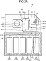
- FIGS. 2A and 2B are views each illustrating an example of a flow of bills at time of depositing.
- the acceptance unit 30 accepts the bills 15 from the user in the storage space 31.
- the control unit 70 controls the conveyance mechanism 60 to take out the bills 15 stored in the storage space 31 one by one.
- the control unit 70 then controls the conveyance mechanism 60 to convey the bills 15 that have been taken out to the determination unit 40 through the conveyance paths 61A, 61B, and 61D, as illustrated in FIG.
- the determination unit 40 determines the types of the bills 15.
- the control unit 70 controls the conveyance mechanism 60 and the temporary holding unit 50 to convey the bills 15 whose types have been determined by the determination unit 40 to the temporary holding unit 50 through the conveyance paths 61H, 61G, and 61F, and temporarily holds the bills 15 in the temporary holding unit 50.
- the control unit 70 displays information according to the determination result by the determination unit 40 in an operation panel of the acceptance unit 30. For example, the control unit 70 displays an amount of money based on the types of the bills 15.
- control unit 70 conveys the bills 15 held in the temporary holding unit 50 to the storage space 31 of the acceptance unit 30 by following the route opposite to the route at time of depositing.
- the control unit 70 controls the conveyance mechanism 60 and the temporary holding unit 50 to take out the bills 15 temporarily held in the temporary holding unit 50, as illustrated in FIG. 2B .
- the control unit 70 controls the conveyance mechanism 60 to convey the bills 15 that have been taken out to the determination unit 40 through the conveyance paths 61F, 61E, and 61D, and the determination unit 40 determines the types of the bills 15 again.
- the control unit 70 controls the conveyance mechanism 60 to store the bills 15 whose types have been determined by the determination unit 40 in the cassettes 20 for each type.
- the control unit 70 stores the bills 15 in separate cassettes 20 for each denomination such as 10,000 bill, 5,000 bill, and 1,000 bill. Note that the control unit 70 may store the same type of bills 15 in the plurality of cassettes 20 separately.
- the control unit 70 controls the conveyance mechanism 60 to convey the bills 15 whose types have been determined by the determination unit 40 to the cassettes 20B to 20E through the conveyance paths 61H, 611, 61K, and 61M. Moreover, the control unit 70 controls the conveyance mechanism 60 to convey the bills 15 whose types have been determined by the determination unit 40 to the cassette 20A through the conveyance paths 61H, 611, 61J, and 61L. Note that the control unit 70 may control the conveyance mechanism 60 to convey the bills 15 whose types have been determined by the determination unit 40 to the cassettes 20B to 20E through the conveyance paths 61H, 611, 61J, 61L, and 61M.
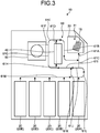
- FIG. 3 is a view illustrating an example of a flow of bills at time of dispensing.
- the control unit 70 specifies a combination of the bills 15 that becomes the specified amount of money.
- the control unit 70 controls the conveyance mechanism 60 to take out the bills 15 one by one from the cassettes 20B to 20E.
- the control unit 70 then controls the conveyance mechanism 60 to convey the bills 15 that have been taken out to the determination unit 40 through the conveyance paths 61M, 61K, 611, and 61H and the determination unit 40 determines the types of the bills 15.
- the control unit 70 controls the conveyance mechanism 60 to take out the bills 15 one by one from the cassette 20A.
- the control unit 70 then controls the conveyance mechanism 60 to convey the bills 15 that have been taken out to the determination unit 40 through the conveyance paths 61L, 61J, 611, and 61H and the determination unit 40 determines the types of the bills 15.
- the control unit 70 may convey the bills 15 that have been stored in the cassettes 20B to 20E to the determination unit 40 through the conveyance paths 61M, 61L, 61J, 611, and 61H.
- the control unit 70 then controls the conveyance mechanism 60 to convey the bills 15 whose types have been determined by the determination unit 40 to the storage space 31 of the acceptance unit 30 through the conveyance paths 61D, 61B, and 61A.
- FIGS. 4A and 4B are views each illustrating an example of a flow of bills at time of examination.
- the bill handling device 10 examines the bills 15 while moving the bills 15 among the cassettes 20.
- the bill handling device 10 empties any one of the cassettes 20.
- the bill handling device 10 empties the cassette 20A.
- the cassette 20A may be empty in advance.
- the bill handling device 10 may empty the cassettes 20 by moving the bills 15 stored in the cassette 20A to the cassettes 20B to 20E.
- the control unit 70 controls the conveyance mechanism 60 to take out the bills 15 one by one from the cassettes 20B to 20E, as illustrated in FIG. 4A .
- the control unit 70 then controls the conveyance mechanism 60 to convey the bills 15 that have been taken out to the determination unit 40 through the conveyance paths 61M, 61K, 611, and 61H and the determination unit 40 determines the types of the bills 15.
- the control unit 70 then controls the conveyance mechanism 60 to convey the bills 15 whose types have been determined by the determination unit 40 to the cassette 20A through the conveyance paths 61D, 61B, 61C, and 61L.
- the control unit 70 controls the conveyance mechanism 60 to take out the bills 15 one by one from the cassette 20A, as illustrated in FIG. 4B .
- the control unit 70 then controls the conveyance mechanism 60 to convey the bills 15 that have been taken out to the determination unit 40 through the conveyance paths 61L, 61C, 61B, and 61D and the determination unit 40 determines the types of the bills 15.
- the control unit 70 then controls the conveyance mechanism 60 to convey the bills 15 whose types have been determined by the determination unit 40 to the cassettes 20 to 20E through the conveyance paths 61H, 611, 61K, and 61M.
- the bill handling device 10 can includes basic functions related to bill handling such as bill depositing, bill dispensing, and bill examination.
- FIG. 5 is a view illustrating examples of detachable units.
- detachable units are indicated with broken lines.
- the temporary holding unit 50, the cassettes 20, and a part of the conveyance mechanism 60 are detachable. In this way, the bill handling device 10 according to the embodiment ensures high expansibility.
- the bill handling device 10 can be configured by the acceptance unit 30, the determination unit 40, two of the cassettes 20 (20A and 20B), and the conveyance mechanism 60 as a minimum configuration.
- FIG. 6A is a view illustrating an example of the bill handling device with a minimum configuration.
- the bill handling device 10 can be configured by the acceptance unit 30, the determination unit 40, two of the cassettes 20 (20A and 20B), and the conveyance mechanism 60 as a minimum configuration.
- the conveyance mechanism 60 of the minimum configuration the conveyance path 61B is connected with the conveyance port 41A of the determination unit 40 and the conveyance path 611 is connected with the conveyance port 41B of the determination unit 40.
- the bill handling device 10 can realize bill depositing, bill dispensing, and bill examination even with the minimum configuration.
- FIG. 6B is a view illustrating an example of a flow of bills at time of depositing with the minimum configuration.
- the control unit 70 controls the conveyance mechanism 60 to take out the bills 15 stored in the storage space 31 one by one.
- the control unit 70 then controls the conveyance mechanism 60 to convey the bills 15 that have been taken out to the determination unit 40 through the conveyance paths 61A and 61B and the determination unit 40 determines the types of the bills 15.
- the control unit 70 then controls the conveyance mechanism 60 to convey the bills 15 whose types have been determined by the determination unit 40 to the cassette 20B through the conveyance paths 611, 61K, and 61M.
- control unit 70 controls the conveyance mechanism 60 to convey the bills 15 whose types have been determined by the determination unit 40 to the cassette 20A through the conveyance paths 611, 61J, and 61L.
- control unit 70 may control the conveyance mechanism 60 to convey the bills 15 whose types have been determined by the determination unit 40 to the cassette 20B through the conveyance paths 611, 61J, 61L, and 61M.
- FIG. 6C is a view illustrating an example of a flow of bills at time of dispensing with the minimum configuration.
- the control unit 70 specifies a combination of the bills 15 that becomes the specified amount of money.
- the control unit 70 controls the conveyance mechanism 60 to take out the bills 15 one by one from the cassette 20B.
- the control unit 70 then controls the conveyance mechanism 60 to convey the bills 15 that have been taken out to the determination unit 40 through the conveyance paths 61M, 61K, and 611 and the determination unit 40 determines the types of the bills 15.
- the control unit 70 controls the conveyance mechanism 60 to take out the bills 15 one by one from the cassette 20A.
- the control unit 70 then controls the conveyance mechanism 60 to convey the bills 15 that have been taken out to the determination unit 40 through the conveyance paths 61L, 61J, and 611 and the determination unit 40 determines the types of the bills 15.
- the control unit 70 may also convey the bills that have been stored in the cassette 20B to the determination unit 40 through the conveyance paths 61M, 61L, 61J, and 611.
- the control unit 70 then controls the conveyance mechanism 60 to convey the bills 15 whose types have been determined by the determination unit 40 to the storage space 31 of the acceptance unit 30 through the conveyance paths 61D, 61B, and 61A.
- FIG. 6D is a view illustrating an example of a flow of bills at time of examination with the minimum configuration.
- the bill handling device 10 examines the bills 15 while moving the bills 15 among the cassettes 20. For example, when the bills 15 stored in the cassette 20B are examined, the control unit 70 controls the conveyance mechanism 60 to take out the bills 15 one by one from the cassette 20B. The control unit 70 then controls the conveyance mechanism 60 to convey the bills 15 that have been taken out to the determination unit 40 through the conveyance paths 61M, 61K, and 611 and the determination unit 40 determines the types of the bills 15. The control unit 70 then controls the conveyance mechanism 60 to convey the bills 15 whose types have been determined by the determination unit 40 to the cassette 20A through the conveyance paths 61B, 61C, and 61L.
- the bill handling device 10 may include a cassette for rejection that takes in the bills 15 unsuitable for recycling such as the bills 15 that are damaged and the bills 15 with a dirt.
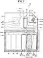
- FIG. 7 is a view illustrating an example of a configuration of the bill handling device provided with a cassette for rejection.
- the three cassettes 20A to 20C are arranged side by side, and the second cassette 20B is the cassette for rejection.
- the first cassette 20A may be the cassette for rejection.
- the opening 21B is provided above a space between the cassette 20B which is the second from the one end and the cassette 20C which is the third from the one end.
- the cassettes 20 indicated with broken lines may be added as cassettes for rejection.
- the bill handling device 10 can store the bills 15 that have been determined to be unsuitable for recycling by the determination unit 40 at time of depositing in the cassettes for rejection.
- the bill handling device 10 of the embodiment includes the case 11A, the case 11B, and the conveyance mechanism 60.
- the case 11A is provided with the acceptance unit 30 and the determination unit 40.
- the acceptance unit 30 accepts the bills 15.
- the determination unit 40 determines the types of the bills 15 that are conveyed between the two conveyance ports 41A and 41B.
- the case 11B the bills 15 can pass from and to the case 11A through the openings 21A and 21B in two locations, and the plurality of cassettes 20 that can store the bills 15 can be arranged.
- the conveyance mechanism 60 is arranged inside the case 11A and the case 11B.
- the conveyance mechanism 60 can convey the bills 15 to the openings 21A and 21B in two locations.
- the conveyance mechanism 60 can convey the bills 15 between the acceptance unit 30 and the plurality of cassettes 20 through the determination unit 40.
- the conveyance mechanism 60 can convey the bills 15 from any cassette of the plurality of cassettes 20 to other cassettes through the determination unit 40. In this way, the bill handling device 10 can ensure high expandability.
- the plurality of cassettes 20 can be arranged side by side in the case 11B.
- the opening 21A which is one of the openings 21A and 21B in two locations, is provided at one end of the plurality of cassettes 20, and the opening 21B, which is another one, is provided leaving a space corresponding to a width of one or two cassettes from the one end.
- the conveyance mechanism 60 has the conveyance path 61L between the opening 21A and the opening 21B, and the conveyance path 61M from the opening 21B to the other end side of the plurality of cassettes 20. In this way, when the number of the cassettes 20 is increased, the bill handling device 10 can arrange the cassettes 20 along the conveyance path 61M, whereby the number of the cassettes 20 can be increased with a little change in the conveyance path.
- the conveyance mechanism 60 conveys the bills 15 from any of the cassettes 20 to the determination unit 40 using one of the conveyance path 61L and the conveyance path 61M. Moreover, the conveyance mechanism 60 conveys the bills 15 whose types have been determined by the determination unit 40 to the other cassettes 20 using another one of the conveyance path 61L and the conveyance path 61M. In this way, the bill handling device 10 can examine the bills 15 inside the plurality of cassettes 20.
- FIG. 8 is a view illustrating another example of a conveyance path of the bill handling device according to the embodiment.
- the conveyance path 611 is connected with the conveyance port 41B of the determination unit 40.
- the conveyance path 61G may be branched from the conveyance path 61K or the conveyance path 61L.
- FIG. 9 is a view illustrating another example of a conveyance path of the bill handling device according to the embodiment. In the bill handling device 10 illustrated in FIG.
- an opening 21C is formed in the case 11B, and the bills 15 can pass between the case 11A and the case 11B through the openings 21A, 21B, and 21C.
- the conveyance path 611 is connected with the conveyance port 41B of the determination unit 40.
- the conveyance path 61G may be branched from the conveyance path 61M through the opening 21C.
- the bill handling device 10 may be a type in which the acceptance unit 30 is separated for depositing and dispensing.
- FIG. 10 is a view illustrating another example of a configuration of the bill handling device according to the embodiment.
- the bill handling device 10 illustrated in FIG. 10 is provided with an acceptance unit 30A for depositing and an acceptance unit 30B for dispensing.
- the conveyance path 61A is connected with the acceptance unit 30B for dispensing.
- a conveyance path 61N branched from the conveyance path 61B is connected with the acceptance unit 30A for depositing.
- the bill handling device 10 may be a type in which the acceptance unit 30 is separated for depositing and dispensing.
- the paper sheets are the bills 15
- the present invention is not limited thereto.
- the paper sheets may be securities such as bills, checks, gift certificates, various securities, and stock certificates.
Landscapes
- Physics & Mathematics (AREA)
- General Physics & Mathematics (AREA)
- Engineering & Computer Science (AREA)
- Mechanical Engineering (AREA)
- Separation, Sorting, Adjustment, Or Bending Of Sheets To Be Conveyed (AREA)
- Pile Receivers (AREA)
Abstract
Description
- The present invention relates to a paper sheet handling device.
- A bill handling device that handles bills such as an automated teller machine (ATM) installed in a bank and the like and a cash dispenser installed in a back office of a store and the like has been conventionally known. Such a bill handling device provided with, for example, an acceptance unit in which a conveyance path capable of conveying bills is formed in a loop shape to accept the bills along the conveyance path, a determination unit that determines types of the bills, and a plurality of storage units that stores the bills.
- Patent Literature 1: International Publication No.
2016/203552 - By the way, a bill handling device can ensure security of the inside when the entire case body is constituted of a thick metal plate and configured such that only limited persons can open the case body. However, in a case where a failure such as a bill conveyance failure occurs inside, only the limited persons can open the case body, and thus maintenance performance declines.
- Therefore, bill handling devices having a structure in which the inside is divided into a plurality of cases so as to suppress a decline in the maintenance performance and ensure security have been increasing. For example, in a bill handling device, the inside is divided into an upper case and a lower case, an acceptance unit that accepts bills and a determination unit that determines the types of the bills are arranged in the upper case, and a cassette that stores and keeps the bills is arranged in the lower case. The lower case is enclosed with a thick metal plate and is high-order security that can be accessed by only limited persons. In this way, the bill handling device can ensure security of the inside of the lower case even when the inside of the upper case is maintained.
- However, when the inside is divided into a plurality of cases, conveyance paths capable of conveying bills between the cases are limited, and thus expandability decreases.
- Note that the problem described above occurs in the conventional paper sheet handling devices that handles paper sheets.
- In view of the above, an object of the disclosed technique is to provide a paper sheet handling device that can ensure high expandability.
- According to an aspect of an embodiment, a paper sheet handling device includes a first case, a second and a conveyance mechanism. The first case is provided with an acceptance unit that accepts paper sheets and a determination unit that determines types of paper sheets that are conveyed between two conveyance ports. The second case can pass paper sheets from and to the first case through openings in two locations and can equip a plurality of cassettes capable of storing paper sheets. The conveyance mechanism is arranged in the first case and the second case, can convey paper sheets to the openings in two locations regarding at least one conveyance port of the two conveyance ports of the determination unit, can convey paper sheets between the acceptance unit and the plurality of cassettes through the determination unit, and can convey paper sheets from any cassette of the plurality of cassettes to other cassettes through the determination unit.
- According to an aspect of the disclosure, high expandability can be ensured.
-
-
FIG. 1 is a view illustrating an example of a configuration of a bill handling device according to an embodiment. -
FIG. 2A is a view illustrating an example of a flow of bills at time of depositing. -
FIG. 2B is a view illustrating an example of a flow of bills at time of depositing. -
FIG. 3 is a view illustrating an example of a flow of bills at time of dispensing. -
FIG. 4A is a view illustrating an example of a flow of bills at time of examination. -
FIG. 4B is a view illustrating an example of a flow of bills at time of examination. -
FIG. 5 is a view illustrating examples of detachable units. -
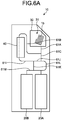
FIG. 6A is a view illustrating an example of the bill handling device with a minimum configuration. -
FIG. 6B is a view illustrating an example of a flow of bills at time of depositing with the minimum configuration. -
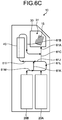
FIG. 6C is a view illustrating an example of a flow of bills at time of depositing with the minimum configuration. -
FIG. 6D is a view illustrating an example of a flow of bills at time of examination with the minimum configuration. -
FIG. 7 is a view illustrating an example of a configuration of the bill handling device provided with a cassette for rejection. -
FIG. 8 is a view illustrating another example of a conveyance path of the bill handling device according to the embodiment. -
FIG. 9 is a view illustrating another example of a conveyance path of the bill handling device according to the embodiment. -
FIG. 10 is a view illustrating another example of a configuration of the bill handling device according to the embodiment. - An embodiment of a paper sheet handling device according to the present disclosure is described below with reference to the drawings. Note that in the following embodiment, a case in which bills are exemplified as paper sheets and a bill handling device is exemplified as a paper sheet handling device will be described as an example. However, the disclosed technique is not limited thereto. Embodiment
-
FIG. 1 is a view illustrating an example of a configuration of a bill handling device according to an embodiment. Abill handling device 10 is a device that handles bills such as an ATM and a cash dispenser. - In order to secure high expandability, various units are detachable from the
bill handling device 10. Thebill handling device 10 is configured to be capable of responding to various customer requests through combining of various units according to mounted functions such as bill depositing, bill dispensing, and bill examination.
For example, thebill handling device 10 can be configured as an ATM or a cash dispenser through combining of various units.FIG.1 illustrates an example of combination of units needed for basic functions related to bill handling such as bill depositing, bill dispensing, and bill examination. - The
bill handling device 10 has acase body 12 that is composed of a plurality ofcases 11. For example, thebill handling device 10 of the embodiment has thecase body 12 composed of anupper case 11A and alower case 11B. - The
case 11B is enclosed with a thick metal plate and has a configuration like a safe box, and is a relatively high-order security area that can be accessed by only limited persons such as a manager, for example. A plurality ofcassettes 20 is arranged side by side inside thecase 11B. In the embodiment, fivecassettes 20A to 20E are arranged side by side inside thecase 11B. - The
case 11B hasopenings case 11A, andbills 15 can pass between thecase 11A and thecase 11B through theopenings case 11B declines as the number of formed openings increases. In thebill handling device 10 of the embodiment, in order to suppress a decline in the security of thecase 11B, the number of openings is two. Theopening 21A is provided at one end of the plurality ofcassettes 20 arranged side by side. In the embodiment, theopening 21A is provided above thecassette 20A which is the first from the one end. Theopening 21B is provided leaving a space corresponding to a width of one to two of thecassettes 20 from the one end. In the embodiment, theopening 21B is provided above a space between thecassette 20A which is the first from the one end and thecassette 20B which is the second from the one end. - As compared with the
case 11B, thecase 11A is a low-order security area, and is provided with anacceptance unit 30, adetermination unit 40, and atemporary holding unit 50. - By composing the
case body 12 by thecases bill handling device 10 can maintain the security inside thecase 11B even when a maintenance operator maintains thecase 11A, for example. - The
acceptance unit 30 accepts at least one of depositing and dispensing of thebills 15. For example, theacceptance unit 30 is provided with an operation panel, which is not illustrated, for accepting various operations. Moreover, theacceptance unit 30 is provided with astorage space 31 in which thebills 15 deposited and dispensed by the user is stored. - The
determination unit 40 determines the types of thebills 15. For example, thedetermination unit 40 has twoconveyance ports 41A and 41B, and is configured to allow thebills 15 to pass between theconveyance ports 41A and 41B. Thedetermination unit 40 determines the types and authenticity of thebills 15 when thebills 15 pass between theconveyance ports 41A and 41B. For example, thedetermination unit 40 determines denominations of thebills 15 as types of thebills 15. Note that thedetermination unit 40 may determine the degree of damage or dirt of thebills 15. - The
temporary holding unit 50 temporarily holds thebills 15. For example, thetemporary holding unit 50 is a winding type holding unit having a band-shaped tape and a winding drum. Thetemporary holding unit 50 can temporarily store thebills 15 by sandwiching thebills 15 between strips of the tape when the winding drum winds the tape, and take out the storedbills 15 by rewinding the tape from the winding drum. - The
bill handling device 10 is provided with aconveyance mechanism 60 that conveys thebills 15 in theupper case 11A and thelower case 11B. Theconveyance mechanism 60 includes aconveyance path 61 for moving thebills 15 inside thecase 11A and thecase 11B and is provided with a motor, a roller, and the like, which are not illustrated, for moving thebills 15 along theconveyance path 61. Theconveyance path 61 branches according to a route for moving thebills 15. Moreover, in theconveyance path 61, a switching mechanism such as a switching claw that switches a conveyance direction of thebills 15 is arranged in a branching point in which the route branches, and thus the route through which thebills 15 are conveyed can be switched. For example, aconveyance path 61A is connected with theacceptance unit 30. Theconveyance path 61A is branched into aconveyance path 61B and aconveyance path 61C at a branchingpoint 62A. Theconveyance path 61B is branched into aconveyance path 61D and aconveyance path 61E at a branchingpoint 62B. Theconveyance path 61D is connected with theconveyance port 41A of thedetermination unit 40. Theconveyance path 61E is branched into aconveyance path 61F and aconveyance path 61G at a branchingpoint 62C. Theconveyance path 61F is connected with thetemporary holding unit 50. Theconveyance path 61G is branched into aconveyance path 61H and aconveyance path 611 at a branching point 62D. Theconveyance path 61H is connected with the conveyance port 41B of thedetermination unit 40. Theconveyance path 611 is branched into aconveyance path 61J and aconveyance path 61K at a branchingpoint 62E. Theconveyance path 61K passes through theopening 21B. Theconveyance path 61J is branched into the above-mentionedconveyance path 61C and aconveyance path 61L at a branchingpoint 62F. Theconveyance path 61L passes through theopening 21A, is arranged above thecassettes 20, and branched into the above-mentionedconveyance path 61K and aconveyance path 61M at a branchingpoint 62G. Theconveyance path 61L is provided with a branch to thefirst cassette 20A. Theconveyance path 61M is arranged above thecassettes 20 and provided with branches to the second tofifth cassettes 20B to 20E. - In the
conveyance mechanism 60, theconveyance paths conveyance mechanism 60, theconveyance paths - Regarding at least one of the two
conveyance ports 41A and 41B of thedetermination unit 40, theconveyance mechanism 60 can convey thebills 15 to theopenings conveyance ports 41A and 41B, theconveyance mechanism 60 of the embodiment can convey thebills 15 to theopenings bills 15 to pass through theconveyance paths conveyance mechanism 60 can convey thebills 15 from the conveyance port 41B to theopening 21B. Moreover, by causing thebills 15 to pass through theconveyance paths conveyance mechanism 60 can convey thebills 15 from the conveyance port 41B to theopening 21A. Moreover, by causing thebills 15 to pass through theconveyance paths conveyance mechanism 60 can convey thebills 15 from theconveyance port 41A to theopening 21B. Moreover, by causing thebills 15 to pass through theconveyance paths conveyance mechanism 60 can convey thebills 15 from theconveyance port 41A to theopening 21A. - The
conveyance mechanism 60 can convey thebills 15 between theacceptance unit 30 and the plurality ofcassettes 20 through thedetermination unit 40. For example, by causing thebills 15 to pass through theconveyance paths conveyance mechanism 60 can convey thebills 15 from theacceptance unit 30 to thecassettes 20B to 20E through thedetermination unit 40. Moreover, by causing thebills 15 to pass through theconveyance paths conveyance mechanism 60 can convey thebills 15 from theacceptance unit 30 to thecassette 20A through thedetermination unit 40. - Moreover, the
conveyance mechanism 60 can convey thebills 15 from any cassette of the plurality ofcassettes 20 to theother cassettes 20 through thedetermination unit 40. For example, by causing thebills 15 to pass through theconveyance paths conveyance mechanism 60 can convey thebills 15 between thecassette 20A and thecassettes 20B to 20E through thedetermination unit 40. - The
conveyance mechanism 60 has theconveyance paths 61A to 61M as described above to allow thebills 15 to pass through thedetermination unit 40 when thebills 15 are handled. - The
bill handling device 10 has acontrol unit 70 that controls the entire device. For example, thecontrol unit 70 is a computer, and includes a central processing unit (CPU), a random access memory (RAM), a read only memory (ROM), an auxiliary storage device, and the like. Thecontrol unit 70 is electrically connected to each of theacceptance unit 30, thedetermination unit 40, thetemporary holding unit 50, and theconveyance mechanism 60. In thecontrol unit 70, the CPU controls various operations such as bill depositing, bill dispensing, and bill examination through control of theacceptance unit 30, thedetermination unit 40, thetemporary holding unit 50, and theconveyance mechanism 60 based on programs stored in the ROM or the auxiliary storage device, and various data. Thecontrol unit 70 controls theconveyance mechanism 60 so as to allow thebills 15 to pass through thedetermination unit 40 when thebills 15 are handled for depositing, dispensing, examination, and the like. - Next, operations of the
bill handling device 10 configured in this way will be described. First, the operation of depositing thebills 15 will be described. Note that in each of the following drawings, illustrations of configurations of parts related to thecontrol unit 70 will be omitted.FIGS. 2A and2B are views each illustrating an example of a flow of bills at time of depositing. Theacceptance unit 30 accepts thebills 15 from the user in thestorage space 31. In the case of the depositing operation, thecontrol unit 70 controls theconveyance mechanism 60 to take out thebills 15 stored in thestorage space 31 one by one. Thecontrol unit 70 then controls theconveyance mechanism 60 to convey thebills 15 that have been taken out to thedetermination unit 40 through theconveyance paths FIG. 2A , and thedetermination unit 40 determines the types of thebills 15. Thecontrol unit 70 then controls theconveyance mechanism 60 and thetemporary holding unit 50 to convey thebills 15 whose types have been determined by thedetermination unit 40 to thetemporary holding unit 50 through theconveyance paths bills 15 in thetemporary holding unit 50. Thecontrol unit 70 displays information according to the determination result by thedetermination unit 40 in an operation panel of theacceptance unit 30. For example, thecontrol unit 70 displays an amount of money based on the types of thebills 15. When receiving an operation that reports that the amount of money is incorrect from the user with respect to the operation panel, or when receiving an operation of cancelling depositing, thecontrol unit 70 conveys thebills 15 held in thetemporary holding unit 50 to thestorage space 31 of theacceptance unit 30 by following the route opposite to the route at time of depositing. - On the other hand, when receiving an operation that reports that the amount of money is correct from the user with respect to the operation panel, the
control unit 70 controls theconveyance mechanism 60 and thetemporary holding unit 50 to take out thebills 15 temporarily held in thetemporary holding unit 50, as illustrated inFIG. 2B . Thecontrol unit 70 then controls theconveyance mechanism 60 to convey thebills 15 that have been taken out to thedetermination unit 40 through theconveyance paths determination unit 40 determines the types of thebills 15 again. Thecontrol unit 70 then controls theconveyance mechanism 60 to store thebills 15 whose types have been determined by thedetermination unit 40 in thecassettes 20 for each type. For example, thecontrol unit 70 stores thebills 15 inseparate cassettes 20 for each denomination such as 10,000 bill, 5,000 bill, and 1,000 bill. Note that thecontrol unit 70 may store the same type ofbills 15 in the plurality ofcassettes 20 separately. - The
control unit 70 controls theconveyance mechanism 60 to convey thebills 15 whose types have been determined by thedetermination unit 40 to thecassettes 20B to 20E through theconveyance paths control unit 70 controls theconveyance mechanism 60 to convey thebills 15 whose types have been determined by thedetermination unit 40 to thecassette 20A through theconveyance paths control unit 70 may control theconveyance mechanism 60 to convey thebills 15 whose types have been determined by thedetermination unit 40 to thecassettes 20B to 20E through theconveyance paths - Next, the operation of dispensing of the
bills 15 will be described.FIG. 3 is a view illustrating an example of a flow of bills at time of dispensing. When receiving the operation of dispensing from the user with respect to the operation panel, thecontrol unit 70 specifies a combination of thebills 15 that becomes the specified amount of money. When the specifiedbills 15 are stored in thecassettes 20B to 20E, thecontrol unit 70 controls theconveyance mechanism 60 to take out thebills 15 one by one from thecassettes 20B to 20E. Thecontrol unit 70 then controls theconveyance mechanism 60 to convey thebills 15 that have been taken out to thedetermination unit 40 through theconveyance paths determination unit 40 determines the types of thebills 15. Moreover, when the specifiedbills 15 are stored in thecassette 20A, thecontrol unit 70 controls theconveyance mechanism 60 to take out thebills 15 one by one from thecassette 20A. Thecontrol unit 70 then controls theconveyance mechanism 60 to convey thebills 15 that have been taken out to thedetermination unit 40 through theconveyance paths determination unit 40 determines the types of thebills 15. Note that thecontrol unit 70 may convey thebills 15 that have been stored in thecassettes 20B to 20E to thedetermination unit 40 through theconveyance paths - The
control unit 70 then controls theconveyance mechanism 60 to convey thebills 15 whose types have been determined by thedetermination unit 40 to thestorage space 31 of theacceptance unit 30 through theconveyance paths - Next, the operation of examination of the
bills 15 will be described.FIGS. 4A and4B are views each illustrating an example of a flow of bills at time of examination. Thebill handling device 10 examines thebills 15 while moving thebills 15 among thecassettes 20. In order to store the examinedbills 15, thebill handling device 10 empties any one of thecassettes 20. For example, thebill handling device 10 empties thecassette 20A. Thecassette 20A may be empty in advance. Alternatively, thebill handling device 10 may empty thecassettes 20 by moving thebills 15 stored in thecassette 20A to thecassettes 20B to 20E. - When examining the
bills 15 stored in thecassettes 20B to 20E, thecontrol unit 70 controls theconveyance mechanism 60 to take out thebills 15 one by one from thecassettes 20B to 20E, as illustrated inFIG. 4A . Thecontrol unit 70 then controls theconveyance mechanism 60 to convey thebills 15 that have been taken out to thedetermination unit 40 through theconveyance paths determination unit 40 determines the types of thebills 15. Thecontrol unit 70 then controls theconveyance mechanism 60 to convey thebills 15 whose types have been determined by thedetermination unit 40 to thecassette 20A through theconveyance paths - On the other hand, when examining the
bills 15 stored in thecassette 20A, thecontrol unit 70 controls theconveyance mechanism 60 to take out thebills 15 one by one from thecassette 20A, as illustrated inFIG. 4B . Thecontrol unit 70 then controls theconveyance mechanism 60 to convey thebills 15 that have been taken out to thedetermination unit 40 through theconveyance paths determination unit 40 determines the types of thebills 15. Thecontrol unit 70 then controls theconveyance mechanism 60 to convey thebills 15 whose types have been determined by thedetermination unit 40 to thecassettes 20 to 20E through theconveyance paths - In this way, the
bill handling device 10 according to the embodiment can includes basic functions related to bill handling such as bill depositing, bill dispensing, and bill examination. - Moreover, as described above, in order to secure high expandability, various units are detachable from the
bill handling device 10.FIG. 5 is a view illustrating examples of detachable units. InFIG. 5 , detachable units are indicated with broken lines. For example, in thebill handling device 10, thetemporary holding unit 50, thecassettes 20, and a part of theconveyance mechanism 60 are detachable. In this way, thebill handling device 10 according to the embodiment ensures high expansibility. - In
FIG. 5 , units needed for a minimum configuration are indicated with solid lines. Thebill handling device 10 can be configured by theacceptance unit 30, thedetermination unit 40, two of the cassettes 20 (20A and 20B), and theconveyance mechanism 60 as a minimum configuration. -
FIG. 6A is a view illustrating an example of the bill handling device with a minimum configuration. Thebill handling device 10 can be configured by theacceptance unit 30, thedetermination unit 40, two of the cassettes 20 (20A and 20B), and theconveyance mechanism 60 as a minimum configuration. In theconveyance mechanism 60 of the minimum configuration, theconveyance path 61B is connected with theconveyance port 41A of thedetermination unit 40 and theconveyance path 611 is connected with the conveyance port 41B of thedetermination unit 40. Thebill handling device 10 can realize bill depositing, bill dispensing, and bill examination even with the minimum configuration. -
FIG. 6B is a view illustrating an example of a flow of bills at time of depositing with the minimum configuration. Thecontrol unit 70 controls theconveyance mechanism 60 to take out thebills 15 stored in thestorage space 31 one by one. Thecontrol unit 70 then controls theconveyance mechanism 60 to convey thebills 15 that have been taken out to thedetermination unit 40 through theconveyance paths determination unit 40 determines the types of thebills 15. Thecontrol unit 70 then controls theconveyance mechanism 60 to convey thebills 15 whose types have been determined by thedetermination unit 40 to thecassette 20B through theconveyance paths control unit 70 controls theconveyance mechanism 60 to convey thebills 15 whose types have been determined by thedetermination unit 40 to thecassette 20A through theconveyance paths control unit 70 may control theconveyance mechanism 60 to convey thebills 15 whose types have been determined by thedetermination unit 40 to thecassette 20B through theconveyance paths -
FIG. 6C is a view illustrating an example of a flow of bills at time of dispensing with the minimum configuration. When receiving the operation of dispensing from the user with respect to the operation panel, thecontrol unit 70 specifies a combination of thebills 15 that becomes the specified amount of money. When the specifiedbills 15 are stored in thecassette 20B, thecontrol unit 70 controls theconveyance mechanism 60 to take out thebills 15 one by one from thecassette 20B. Thecontrol unit 70 then controls theconveyance mechanism 60 to convey thebills 15 that have been taken out to thedetermination unit 40 through theconveyance paths determination unit 40 determines the types of thebills 15. Moreover, when the specifiedbills 15 are stored in thecassette 20A, thecontrol unit 70 controls theconveyance mechanism 60 to take out thebills 15 one by one from thecassette 20A. Thecontrol unit 70 then controls theconveyance mechanism 60 to convey thebills 15 that have been taken out to thedetermination unit 40 through theconveyance paths determination unit 40 determines the types of thebills 15. Note that thecontrol unit 70 may also convey the bills that have been stored in thecassette 20B to thedetermination unit 40 through theconveyance paths - The
control unit 70 then controls theconveyance mechanism 60 to convey thebills 15 whose types have been determined by thedetermination unit 40 to thestorage space 31 of theacceptance unit 30 through theconveyance paths -
FIG. 6D is a view illustrating an example of a flow of bills at time of examination with the minimum configuration. Thebill handling device 10 examines thebills 15 while moving thebills 15 among thecassettes 20. For example, when thebills 15 stored in thecassette 20B are examined, thecontrol unit 70 controls theconveyance mechanism 60 to take out thebills 15 one by one from thecassette 20B. Thecontrol unit 70 then controls theconveyance mechanism 60 to convey thebills 15 that have been taken out to thedetermination unit 40 through theconveyance paths determination unit 40 determines the types of thebills 15. Thecontrol unit 70 then controls theconveyance mechanism 60 to convey thebills 15 whose types have been determined by thedetermination unit 40 to thecassette 20A through theconveyance paths - In addition, the
bill handling device 10 may include a cassette for rejection that takes in thebills 15 unsuitable for recycling such as thebills 15 that are damaged and thebills 15 with a dirt.FIG. 7 is a view illustrating an example of a configuration of the bill handling device provided with a cassette for rejection. InFIG. 7 , the threecassettes 20A to 20C are arranged side by side, and thesecond cassette 20B is the cassette for rejection. Note that thefirst cassette 20A may be the cassette for rejection. - Moreover, in the example of
FIG. 7 , theopening 21B is provided above a space between thecassette 20B which is the second from the one end and thecassette 20C which is the third from the one end. Through arranging of the cassette for rejection between theopening 21A andopening 21B, thebill handling device 10 can store thebills 15 that have been determined to be unsuitable for recycling by thedetermination unit 40 at time of dispensing in the cassette for rejection. - Note that in the
bill handling device 10, thecassettes 20 indicated with broken lines may be added as cassettes for rejection. Through arranging of thecassettes 20 indicated with the broken lines, thebill handling device 10 can store thebills 15 that have been determined to be unsuitable for recycling by thedetermination unit 40 at time of depositing in the cassettes for rejection. - As described above, the
bill handling device 10 of the embodiment includes thecase 11A, thecase 11B, and theconveyance mechanism 60. Thecase 11A is provided with theacceptance unit 30 and thedetermination unit 40. Theacceptance unit 30 accepts thebills 15. Thedetermination unit 40 determines the types of thebills 15 that are conveyed between the twoconveyance ports 41A and 41B. In thecase 11B, thebills 15 can pass from and to thecase 11A through theopenings cassettes 20 that can store thebills 15 can be arranged. Theconveyance mechanism 60 is arranged inside thecase 11A and thecase 11B. Regarding at least one conveyance port of the twoconveyance ports 41A and 41B of thedetermination unit 40, theconveyance mechanism 60 can convey thebills 15 to theopenings conveyance mechanism 60 can convey thebills 15 between theacceptance unit 30 and the plurality ofcassettes 20 through thedetermination unit 40. Theconveyance mechanism 60 can convey thebills 15 from any cassette of the plurality ofcassettes 20 to other cassettes through thedetermination unit 40. In this way, thebill handling device 10 can ensure high expandability. - Moreover, in the
bill handling device 10 of the embodiment, the plurality ofcassettes 20 can be arranged side by side in thecase 11B. In thecase 11B, theopening 21A, which is one of theopenings cassettes 20, and theopening 21B, which is another one, is provided leaving a space corresponding to a width of one or two cassettes from the one end. Theconveyance mechanism 60 has theconveyance path 61L between theopening 21A and theopening 21B, and theconveyance path 61M from theopening 21B to the other end side of the plurality ofcassettes 20. In this way, when the number of thecassettes 20 is increased, thebill handling device 10 can arrange thecassettes 20 along theconveyance path 61M, whereby the number of thecassettes 20 can be increased with a little change in the conveyance path. - Moreover, in the
bill handling device 10 of the embodiment, at time of examination of thebills 15 inside the plurality ofcassettes 20, theconveyance mechanism 60 conveys thebills 15 from any of thecassettes 20 to thedetermination unit 40 using one of theconveyance path 61L and theconveyance path 61M. Moreover, theconveyance mechanism 60 conveys thebills 15 whose types have been determined by thedetermination unit 40 to theother cassettes 20 using another one of theconveyance path 61L and theconveyance path 61M. In this way, thebill handling device 10 can examine thebills 15 inside the plurality ofcassettes 20. - Although the embodiment of the present invention has been described thus far, the present invention may be implemented in various different forms other than the embodiment described above.
- For example, the
conveyance paths 61A to 61M of theconveyance mechanism 60 illustrated inFIG. 1 and the like are examples, and the present invention is not limited thereto.FIG. 8 is a view illustrating another example of a conveyance path of the bill handling device according to the embodiment. In theconveyance mechanism 60 illustrated inFIG. 8 , theconveyance path 611 is connected with the conveyance port 41B of thedetermination unit 40. Moreover, in theconveyance mechanism 60 illustrated inFIG. 8 , theconveyance path 61G may be branched from theconveyance path 61K or theconveyance path 61L.FIG. 9 is a view illustrating another example of a conveyance path of the bill handling device according to the embodiment. In thebill handling device 10 illustrated inFIG. 9 , in addition to theopenings opening 21C is formed in thecase 11B, and thebills 15 can pass between thecase 11A and thecase 11B through theopenings conveyance mechanism 60 illustrated inFIG. 9 , theconveyance path 611 is connected with the conveyance port 41B of thedetermination unit 40. Moreover, in theconveyance mechanism 60 illustrated inFIG. 9 , theconveyance path 61G may be branched from theconveyance path 61M through theopening 21C. - Moreover, the
bill handling device 10 may be a type in which theacceptance unit 30 is separated for depositing and dispensing.FIG. 10 is a view illustrating another example of a configuration of the bill handling device according to the embodiment. Thebill handling device 10 illustrated inFIG. 10 is provided with anacceptance unit 30A for depositing and anacceptance unit 30B for dispensing. Theconveyance path 61A is connected with theacceptance unit 30B for dispensing. Aconveyance path 61N branched from theconveyance path 61B is connected with theacceptance unit 30A for depositing. In this way, thebill handling device 10 may be a type in which theacceptance unit 30 is separated for depositing and dispensing. - Moreover, although, in the above embodiment, a case in which the paper sheets are the
bills 15 is described, the present invention is not limited thereto. For example, the paper sheets may be securities such as bills, checks, gift certificates, various securities, and stock certificates. - 10 BILL HANDLING DEVICE (PAPER SHEET HANDLING DEVICE)
- 11, 11A, 11B
- CASE
- 12
- CASE BODY
- 15
- BILL (PAPER SHEET)
- 20, 20A-20D
- CASSETTE
- 21A, 21B, 21C
- OPENING
- 30, 30A, 30B
- ACCEPTANCE UNIT
- 40
- DETERMINATION UNIT
- 41A, 41B
- CONVEYANCE PORT
- 50
- TEMPORARY HOLDING UNIT
- 60
- CONVEYANCE MECHANISM
- 61, 61A-61M
- CONVEYANCE PATH
- 70
- CONTROL UNIT
Claims (3)
- A paper sheet handling device comprising:a first case provided with an acceptance unit that accepts paper sheets and a determination unit that determines types of paper sheets that are conveyed between two conveyance ports;a second case in which paper sheets can pass from and to the first case through openings in two locations and a plurality of cassettes capable of storing paper sheets can be arranged; anda conveyance mechanism that is arranged in the first case and the second case, can convey paper sheets to the openings in two locations regarding at least one conveyance port of the two conveyance ports of the determination unit, can convey paper sheets between the acceptance unit and the plurality of cassettes through the determination unit, and can convey paper sheets from any cassette of the plurality of cassettes to other cassettes through the determination unit.
- The paper sheet handling device according to claim 1, wherein
in the second case, the plurality of cassettes can be arranged side by side, one opening of the openings in two locations is provided at one end of the plurality of cassettes, and another opening is provided leaving a space corresponding to a width of one or two cassettes from the one end, and
the conveyance mechanism has a first conveyance path between the one opening and the other opening, and a second conveyance path from the other opening to another end side of the plurality of cassettes. - The paper sheet handling device according to claim 2, wherein
at time of examination of paper sheets inside the plurality of cassettes, the conveyance mechanism conveys the paper sheets from any cassette of the plurality of cassettes to the determination unit using one of the first conveyance path and the second conveyance path, and conveys the paper sheets whose types have been determined by the determination unit to other cassettes using another one of the first conveyance path and the second conveyance path.
Applications Claiming Priority (1)
| Application Number | Priority Date | Filing Date | Title |
|---|---|---|---|
| PCT/JP2018/011882 WO2019180958A1 (en) | 2018-03-23 | 2018-03-23 | Paper sheet handing device |
Publications (2)
| Publication Number | Publication Date |
|---|---|
| EP3770871A1 true EP3770871A1 (en) | 2021-01-27 |
| EP3770871A4 EP3770871A4 (en) | 2021-03-31 |
Family
ID=67988303
Family Applications (1)
| Application Number | Title | Priority Date | Filing Date |
|---|---|---|---|
| EP18911256.8A Withdrawn EP3770871A4 (en) | 2018-03-23 | 2018-03-23 | Paper sheet handling device |
Country Status (5)
| Country | Link |
|---|---|
| US (1) | US20200369489A1 (en) |
| EP (1) | EP3770871A4 (en) |
| JP (1) | JPWO2019180958A1 (en) |
| CN (1) | CN111742355A (en) |
| WO (1) | WO2019180958A1 (en) |
Families Citing this family (1)
| Publication number | Priority date | Publication date | Assignee | Title |
|---|---|---|---|---|
| KR102236783B1 (en) | 2019-11-12 | 2021-04-06 | 효성티앤에스 주식회사 | Automatic teller machine |
Family Cites Families (8)
| Publication number | Priority date | Publication date | Assignee | Title |
|---|---|---|---|---|
| EP1130551A3 (en) * | 2000-02-22 | 2004-01-21 | Glory Kogyo Kabushiki Kaisha | Bill handling machine |
| DE102006028633A1 (en) * | 2006-06-22 | 2007-12-27 | Giesecke & Devrient Gmbh | Processing device for value documents |
| EP2680235B1 (en) * | 2011-02-22 | 2019-10-16 | Glory Ltd. | Paper currency processing device |
| EP3040951A4 (en) * | 2013-08-28 | 2016-09-14 | Fujitsu Frontech Ltd | Banknote transaction device |
| JP6088453B2 (en) * | 2014-02-21 | 2017-03-01 | 富士通フロンテック株式会社 | Bill handling apparatus and bill handling system |
| JP6330109B2 (en) | 2015-06-16 | 2018-05-23 | 富士通フロンテック株式会社 | Paper sheet handling device and paper sheet handling method |
| JP2017151928A (en) * | 2016-02-26 | 2017-08-31 | 沖電気工業株式会社 | Automatic transaction device |
| CN107274549A (en) * | 2017-06-30 | 2017-10-20 | 深圳怡化电脑股份有限公司 | A kind of financial self-service equipment and medium input, output intent |
-
2018
- 2018-03-23 WO PCT/JP2018/011882 patent/WO2019180958A1/en not_active Ceased
- 2018-03-23 JP JP2020507279A patent/JPWO2019180958A1/en active Pending
- 2018-03-23 CN CN201880089713.6A patent/CN111742355A/en active Pending
- 2018-03-23 EP EP18911256.8A patent/EP3770871A4/en not_active Withdrawn
-
2020
- 2020-08-12 US US16/991,692 patent/US20200369489A1/en not_active Abandoned
Also Published As
| Publication number | Publication date |
|---|---|
| JPWO2019180958A1 (en) | 2020-10-22 |
| EP3770871A4 (en) | 2021-03-31 |
| WO2019180958A1 (en) | 2019-09-26 |
| CN111742355A (en) | 2020-10-02 |
| US20200369489A1 (en) | 2020-11-26 |
Similar Documents
| Publication | Publication Date | Title |
|---|---|---|
| KR100323490B1 (en) | Leaflets storing units of bills treatment apparatus | |
| US11393273B2 (en) | Money handling apparatus | |
| US8857598B2 (en) | Paper sheet conveying device and automatic cash transaction device | |
| WO2012002036A1 (en) | Automatic transaction apparatus | |
| US9842324B2 (en) | Banknote processing device, and banknote processing method | |
| US10755513B2 (en) | Banknote processing apparatus | |
| JP6380039B2 (en) | Transport path switching device and medium transaction device | |
| EP4015428B1 (en) | Paper sheet processing device | |
| JP2013204358A (en) | Opening and closing device | |
| JP6413688B2 (en) | Automatic transaction equipment | |
| WO2015174232A1 (en) | Medium storage container and medium transaction device | |
| EP3770871A1 (en) | Paper sheet handling device | |
| KR20160066166A (en) | A banknote recieving/dispensing cassette for two different kinds of banknotes and the ATM equipped with the same | |
| JPH11175801A (en) | Paper handling equipment | |
| JP7058774B2 (en) | Transport direction switching device and paper leaf handling device | |
| JP6237911B2 (en) | Medium transport identification apparatus and medium transaction apparatus | |
| JP6737014B2 (en) | Medium storage and medium processing device | |
| JP2025064572A (en) | Banknote Processing Device | |
| JP2025126769A (en) | Bill processing apparatus | |
| JP6087001B2 (en) | Money handling equipment | |
| JP6087000B2 (en) | Money handling equipment | |
| JP2001307175A (en) | Paper money automatic receiving/dispensing device |
Legal Events
| Date | Code | Title | Description |
|---|---|---|---|
| STAA | Information on the status of an ep patent application or granted ep patent |
Free format text: STATUS: THE INTERNATIONAL PUBLICATION HAS BEEN MADE |
|
| PUAI | Public reference made under article 153(3) epc to a published international application that has entered the european phase |
Free format text: ORIGINAL CODE: 0009012 |
|
| STAA | Information on the status of an ep patent application or granted ep patent |
Free format text: STATUS: REQUEST FOR EXAMINATION WAS MADE |
|
| 17P | Request for examination filed |
Effective date: 20200814 |
|
| AK | Designated contracting states |
Kind code of ref document: A1 Designated state(s): AL AT BE BG CH CY CZ DE DK EE ES FI FR GB GR HR HU IE IS IT LI LT LU LV MC MK MT NL NO PL PT RO RS SE SI SK SM TR |
|
| AX | Request for extension of the european patent |
Extension state: BA ME |
|
| A4 | Supplementary search report drawn up and despatched |
Effective date: 20210225 |
|
| RIC1 | Information provided on ipc code assigned before grant |
Ipc: G07D 11/25 20190101ALI20210219BHEP Ipc: G07D 11/18 20190101ALI20210219BHEP Ipc: B65H 29/60 20060101ALI20210219BHEP Ipc: G07D 7/187 20160101ALI20210219BHEP Ipc: G07D 11/40 20190101AFI20210219BHEP Ipc: B65H 31/24 20060101ALI20210219BHEP Ipc: B65H 83/02 20060101ALI20210219BHEP |
|
| DAV | Request for validation of the european patent (deleted) | ||
| DAX | Request for extension of the european patent (deleted) | ||
| STAA | Information on the status of an ep patent application or granted ep patent |
Free format text: STATUS: THE APPLICATION IS DEEMED TO BE WITHDRAWN |
|
| 18D | Application deemed to be withdrawn |
Effective date: 20210928 |