EP3770611B1 - Method, device and system for correcting installation errors of wind vane - Google Patents
Method, device and system for correcting installation errors of wind vane Download PDFInfo
- Publication number
- EP3770611B1 EP3770611B1 EP19889545.0A EP19889545A EP3770611B1 EP 3770611 B1 EP3770611 B1 EP 3770611B1 EP 19889545 A EP19889545 A EP 19889545A EP 3770611 B1 EP3770611 B1 EP 3770611B1
- Authority
- EP
- European Patent Office
- Prior art keywords
- wind turbine
- wind
- generator
- outer rotor
- blades
- Prior art date
- Legal status (The legal status is an assumption and is not a legal conclusion. Google has not performed a legal analysis and makes no representation as to the accuracy of the status listed.)
- Active
Links
Images




Classifications
-
- F—MECHANICAL ENGINEERING; LIGHTING; HEATING; WEAPONS; BLASTING
- F03—MACHINES OR ENGINES FOR LIQUIDS; WIND, SPRING, OR WEIGHT MOTORS; PRODUCING MECHANICAL POWER OR A REACTIVE PROPULSIVE THRUST, NOT OTHERWISE PROVIDED FOR
- F03D—WIND MOTORS
- F03D7/00—Controlling wind motors
- F03D7/02—Controlling wind motors the wind motors having rotation axis substantially parallel to the air flow entering the rotor
- F03D7/04—Automatic control; Regulation
- F03D7/042—Automatic control; Regulation by means of an electrical or electronic controller
- F03D7/047—Automatic control; Regulation by means of an electrical or electronic controller characterised by the controller architecture, e.g. multiple processors or data communications
-
- F—MECHANICAL ENGINEERING; LIGHTING; HEATING; WEAPONS; BLASTING
- F03—MACHINES OR ENGINES FOR LIQUIDS; WIND, SPRING, OR WEIGHT MOTORS; PRODUCING MECHANICAL POWER OR A REACTIVE PROPULSIVE THRUST, NOT OTHERWISE PROVIDED FOR
- F03D—WIND MOTORS
- F03D17/00—Monitoring or testing of wind motors, e.g. diagnostics
-
- F—MECHANICAL ENGINEERING; LIGHTING; HEATING; WEAPONS; BLASTING
- F03—MACHINES OR ENGINES FOR LIQUIDS; WIND, SPRING, OR WEIGHT MOTORS; PRODUCING MECHANICAL POWER OR A REACTIVE PROPULSIVE THRUST, NOT OTHERWISE PROVIDED FOR
- F03D—WIND MOTORS
- F03D7/00—Controlling wind motors
- F03D7/02—Controlling wind motors the wind motors having rotation axis substantially parallel to the air flow entering the rotor
- F03D7/0204—Controlling wind motors the wind motors having rotation axis substantially parallel to the air flow entering the rotor for orientation in relation to wind direction
-
- G—PHYSICS
- G01—MEASURING; TESTING
- G01P—MEASURING LINEAR OR ANGULAR SPEED, ACCELERATION, DECELERATION, OR SHOCK; INDICATING PRESENCE, ABSENCE, OR DIRECTION, OF MOVEMENT
- G01P13/00—Indicating or recording presence, absence, or direction, of movement
- G01P13/02—Indicating direction only, e.g. by weather vane
-
- G—PHYSICS
- G01—MEASURING; TESTING
- G01P—MEASURING LINEAR OR ANGULAR SPEED, ACCELERATION, DECELERATION, OR SHOCK; INDICATING PRESENCE, ABSENCE, OR DIRECTION, OF MOVEMENT
- G01P21/00—Testing or calibrating of apparatus or devices covered by the preceding groups
-
- G—PHYSICS
- G01—MEASURING; TESTING
- G01P—MEASURING LINEAR OR ANGULAR SPEED, ACCELERATION, DECELERATION, OR SHOCK; INDICATING PRESENCE, ABSENCE, OR DIRECTION, OF MOVEMENT
- G01P21/00—Testing or calibrating of apparatus or devices covered by the preceding groups
- G01P21/02—Testing or calibrating of apparatus or devices covered by the preceding groups of speedometers
- G01P21/025—Testing or calibrating of apparatus or devices covered by the preceding groups of speedometers for measuring speed of fluids; for measuring speed of bodies relative to fluids
-
- G—PHYSICS
- G01—MEASURING; TESTING
- G01P—MEASURING LINEAR OR ANGULAR SPEED, ACCELERATION, DECELERATION, OR SHOCK; INDICATING PRESENCE, ABSENCE, OR DIRECTION, OF MOVEMENT
- G01P5/00—Measuring speed of fluids, e.g. of air stream; Measuring speed of bodies relative to fluids, e.g. of ship, of aircraft
- G01P5/02—Measuring speed of fluids, e.g. of air stream; Measuring speed of bodies relative to fluids, e.g. of ship, of aircraft by measuring forces exerted by the fluid on solid bodies, e.g. anemometer
- G01P5/06—Measuring speed of fluids, e.g. of air stream; Measuring speed of bodies relative to fluids, e.g. of ship, of aircraft by measuring forces exerted by the fluid on solid bodies, e.g. anemometer using rotation of vanes
-
- G—PHYSICS
- G06—COMPUTING OR CALCULATING; COUNTING
- G06T—IMAGE DATA PROCESSING OR GENERATION, IN GENERAL
- G06T5/00—Image enhancement or restoration
- G06T5/70—Denoising; Smoothing
-
- G—PHYSICS
- G06—COMPUTING OR CALCULATING; COUNTING
- G06T—IMAGE DATA PROCESSING OR GENERATION, IN GENERAL
- G06T7/00—Image analysis
- G06T7/0002—Inspection of images, e.g. flaw detection
- G06T7/0004—Industrial image inspection
-
- G—PHYSICS
- G06—COMPUTING OR CALCULATING; COUNTING
- G06T—IMAGE DATA PROCESSING OR GENERATION, IN GENERAL
- G06T7/00—Image analysis
- G06T7/10—Segmentation; Edge detection
- G06T7/13—Edge detection
-
- G—PHYSICS
- G06—COMPUTING OR CALCULATING; COUNTING
- G06T—IMAGE DATA PROCESSING OR GENERATION, IN GENERAL
- G06T7/00—Image analysis
- G06T7/70—Determining position or orientation of objects or cameras
- G06T7/73—Determining position or orientation of objects or cameras using feature-based methods
-
- F—MECHANICAL ENGINEERING; LIGHTING; HEATING; WEAPONS; BLASTING
- F05—INDEXING SCHEMES RELATING TO ENGINES OR PUMPS IN VARIOUS SUBCLASSES OF CLASSES F01-F04
- F05B—INDEXING SCHEME RELATING TO WIND, SPRING, WEIGHT, INERTIA OR LIKE MOTORS, TO MACHINES OR ENGINES FOR LIQUIDS COVERED BY SUBCLASSES F03B, F03D AND F03G
- F05B2270/00—Control
- F05B2270/30—Control parameters, e.g. input parameters
- F05B2270/321—Wind directions
-
- F—MECHANICAL ENGINEERING; LIGHTING; HEATING; WEAPONS; BLASTING
- F05—INDEXING SCHEMES RELATING TO ENGINES OR PUMPS IN VARIOUS SUBCLASSES OF CLASSES F01-F04
- F05B—INDEXING SCHEME RELATING TO WIND, SPRING, WEIGHT, INERTIA OR LIKE MOTORS, TO MACHINES OR ENGINES FOR LIQUIDS COVERED BY SUBCLASSES F03B, F03D AND F03G
- F05B2270/00—Control
- F05B2270/30—Control parameters, e.g. input parameters
- F05B2270/329—Azimuth or yaw angle
-
- F—MECHANICAL ENGINEERING; LIGHTING; HEATING; WEAPONS; BLASTING
- F05—INDEXING SCHEMES RELATING TO ENGINES OR PUMPS IN VARIOUS SUBCLASSES OF CLASSES F01-F04
- F05B—INDEXING SCHEME RELATING TO WIND, SPRING, WEIGHT, INERTIA OR LIKE MOTORS, TO MACHINES OR ENGINES FOR LIQUIDS COVERED BY SUBCLASSES F03B, F03D AND F03G
- F05B2270/00—Control
- F05B2270/80—Devices generating input signals, e.g. transducers, sensors, cameras or strain gauges
- F05B2270/802—Calibration thereof
-
- F—MECHANICAL ENGINEERING; LIGHTING; HEATING; WEAPONS; BLASTING
- F05—INDEXING SCHEMES RELATING TO ENGINES OR PUMPS IN VARIOUS SUBCLASSES OF CLASSES F01-F04
- F05B—INDEXING SCHEME RELATING TO WIND, SPRING, WEIGHT, INERTIA OR LIKE MOTORS, TO MACHINES OR ENGINES FOR LIQUIDS COVERED BY SUBCLASSES F03B, F03D AND F03G
- F05B2270/00—Control
- F05B2270/80—Devices generating input signals, e.g. transducers, sensors, cameras or strain gauges
- F05B2270/804—Optical devices
- F05B2270/8041—Cameras
-
- F—MECHANICAL ENGINEERING; LIGHTING; HEATING; WEAPONS; BLASTING
- F05—INDEXING SCHEMES RELATING TO ENGINES OR PUMPS IN VARIOUS SUBCLASSES OF CLASSES F01-F04
- F05D—INDEXING SCHEME FOR ASPECTS RELATING TO NON-POSITIVE-DISPLACEMENT MACHINES OR ENGINES, GAS-TURBINES OR JET-PROPULSION PLANTS
- F05D2270/00—Control
- F05D2270/80—Devices generating input signals, e.g. transducers, sensors, cameras or strain gauges
- F05D2270/804—Optical devices
- F05D2270/8041—Cameras
-
- G—PHYSICS
- G06—COMPUTING OR CALCULATING; COUNTING
- G06T—IMAGE DATA PROCESSING OR GENERATION, IN GENERAL
- G06T2207/00—Indexing scheme for image analysis or image enhancement
- G06T2207/30—Subject of image; Context of image processing
- G06T2207/30108—Industrial image inspection
- G06T2207/30164—Workpiece; Machine component
-
- Y—GENERAL TAGGING OF NEW TECHNOLOGICAL DEVELOPMENTS; GENERAL TAGGING OF CROSS-SECTIONAL TECHNOLOGIES SPANNING OVER SEVERAL SECTIONS OF THE IPC; TECHNICAL SUBJECTS COVERED BY FORMER USPC CROSS-REFERENCE ART COLLECTIONS [XRACs] AND DIGESTS
- Y02—TECHNOLOGIES OR APPLICATIONS FOR MITIGATION OR ADAPTATION AGAINST CLIMATE CHANGE
- Y02E—REDUCTION OF GREENHOUSE GAS [GHG] EMISSIONS, RELATED TO ENERGY GENERATION, TRANSMISSION OR DISTRIBUTION
- Y02E10/00—Energy generation through renewable energy sources
- Y02E10/70—Wind energy
- Y02E10/72—Wind turbines with rotation axis in wind direction
Definitions
- the present disclosure relates to the field of wind power generation, and in particular, to a method, an apparatus and a system for correcting an installation error of a wind vane.
- a yaw system is an important part of a wind turbine.
- the yaw system is capable to achieve fast and smooth wind alignment when the wind direction changes, so that a wind wheel can acquire maximum wind energy.
- a wind vane serves as a front-end input in a yaw strategy for wind alignment. A deviation in detecting the wind direction by the wind vane would result in a power loss of the wind turbine and an increase in a load of the wind turbine.
- the wind vane of the wind turbine is generally installed on top of a nacelle, and the installation is manually performed.
- a direction of the wind vane is adjusted by a staff, in order to align a marking "S" on a rotating shaft of the wind vane with a head of the wind turbine, or align a marking "N” with a tail of the wind turbine.
- the rotating shaft of the wind vane is fixed on top of the nacelle.
- CN207064155U discloses an installation angle measuring device and system of wind vane.
- the wind vane is installed in wind generating set cabin housing top, and wherein, the installation angle measuring device of wind vane includes: the bearing is fixed in on the rotor plane near the cabin side, angle measurement element sets up in the bearing, and angle measurement element includes portion of measurationing and pivot, and the portion of measurationing upwards centers on the pivot extension in the week of pivot and distributes, can obtain the pivot for a pivoted angle of measurationing through the portion of measurationing, adapting unit, including two tip, one of them tip is connected with the pivot, and another tip is connected with the wind vane, and adapting unit is used for driving the pivot and rotates along with the wind vane.
- the utility model discloses the installation angle measuring device of wind vane can detect the mounted position of wind vane to whether the mountedposition of supplementary snap judgments wind vane is in the tram.
- a Computer Vision Approach for Autonomous Wind Turbine Inspection using a Multicopter discloses the mission of autonomous inspection of a wind turbine using a multicopter. Emphasis was placed on recognition and tracking using image processing methods. The Hough line transform was used to extract features of the wind turbine. Hub position was estimated by an algorithm tailored to identify the three-point star resemblance and was tracked by utilizing the Kalman filter. Distance and yaw orientation of the wind turbine were estimated using the pinhole camera model and coordinate transformations. Restricting computational demand was a goal in the program design. Experiments showed accurate position tracking at long range, but with deteriorating performance as range was decreased. Lack of distinctive measurable lengths in the image caused inaccuracy in estimation of distance and yaw orientation. Execution frequency of below 7 Hz was achieved on a single-board computer which was found to be sufficient for reliable control in flight.
- a method, an apparatus and a system for correcting an installation error of a wind vane is provided according to embodiments of the present disclosure, so as to achieve automatic correction of installation errors of wind vanes and improve accuracy of installation of wind vanes.
- a method for correcting an installation error of a wind vane of a wind turbine according to claim 1 is provided according to an embodiment of the present disclosure.
- obtaining the contour of the blades of the wind turbine and the contour of the outer rotor of the generator from the image of the blades of the wind turbine and the outer rotor of the generator includes: obtaining a grayscale image of the blades of the wind turbine and the outer rotor of the generator, according to the image of the blades of the wind turbine and the outer rotor of the generator; performing edge detection on the grayscale image; and performing contour detection on the grayscale image, according to a result of the edge detection.
- performing the edge detection on the grayscale image of the blades of the wind turbine and the outer rotor of the generator includes: denoising the grayscale image of the blades of the wind turbine and the outer rotor of the generator, through a Gaussian filter; calculating gradient magnitude of a grayscale of each pixel in the grayscale image after the de-noising; performing preset enhancement on the grayscale of each pixel, according to the gradient magnitude; and determining an edge pixel of the blades of the wind turbine and the outer rotor of the generator, according to a relationship between the enhanced grayscale and a preset threshold.
- obtaining the orienting plane of the wind vane includes: obtaining a result of laser orientation on the wind vane; and determining the orienting plane of the wind vane according to the result of the laser orientation.
- calculating the deviation angle between the wind vane and the center line of the wind turbine based on the orienting plane of the wind vane and the first intersection point includes: obtaining an intersection point between the orienting plane of the wind vane and the contour of the outer rotor of the generator, as a second intersection; calculating a quantity of pixels, which are between the first intersection point and the second intersection point, in the image of the blades of the wind turbine and the outer rotor of the generator, where the image is obtained by an image collecting apparatus fixed on the wind vane, and the image collecting apparatus is fixed at a head of the wind vane; calculating a distance represented by each pixel in the image, according to a width of a view field of the image collecting apparatus and a quantity of pixels along a width direction of the image; calculating a deviation distance, between the wind vane and the center line of the wind turbine, corresponding to each angle degree of the deviation angle, according to a distance between the image collecting apparatus and the outer rotor of the generator, where the distance between the
- a apparatus for correcting an installation error of a wind vane of a wind turbine according to claim 6 is provided according to an embodiment of the present disclosure.
- the contour obtaining module is configured to: obtain a grayscale image of the blades of the wind turbine and the outer rotor of the generator, according to the image of the blades of the wind turbine and the outer rotor of the generator; perform edge detection on the grayscale image; and perform contour detection on the grayscale image, according to a result of the edge detection.
- the contour obtaining module is configured to: denoise the grayscale image of the blades of the wind turbine and the outer rotor of the generator, through a Gaussian filter; calculate gradient magnitude of a grayscale of each pixel in the grayscale image after the de-noising; perform preset enhancement on the grayscale of each pixel, according to the gradient magnitude; and determine an edge pixel of the blades of the wind turbine and the outer rotor of the generator, according to a relationship between the enhanced grayscale and a preset threshold.
- the alignment determination module is configured to: obtain a result of laser orientation on the wind vane, and determine the orienting plane of the wind vane according to the result of the laser orientation.
- the angle correction module is configured to: obtain an intersection point between the orienting plane of the wind vane and the contour of the outer rotor of the generator, as a second intersection; calculate a quantity of pixels, which are between the first intersection point and the second intersection point, in the image of the blades of the wind turbine and the outer rotor of the generator, where the image is obtained by an image collecting apparatus fixed on the wind vane, and the image collecting apparatus is fixed at a head of the wind vane; calculate a distance represented by each pixel in the image, according to a width of a view field of the image collecting apparatus and a quantity of pixels along a width direction of the image; calculate a deviation distance, between the wind vane and the center line of the wind turbine, corresponding to each angle degree of the deviation angle, according to a distance between the image collecting apparatus and the outer rotor of the generator, where the distance between the image collecting apparatus and the outer rotor of the generator is obtained through ultrasonic distance measurement; and calculate the deviation angle between the wind vane and the center
- a computer-readable storage medium according to claim 7 is provided according to an embodiment of the present disclosure.
- a computing apparatus according to claim 8 is provided according to an embodiment of the present disclosure.
- a system for correcting an installation error of a wind vane of a wind turbine according to claim 9 is provided according to an embodiment of the present disclosure.
- the processor is further configured to: obtain a grayscale image of the blades of the wind turbine and the outer rotor of the generator, according to the image of the blades of the wind turbine and the outer rotor of the generator; perform edge detection on the grayscale image; and perform contour detection on the grayscale image, according to a result of the edge detection.
- the processor is further configured to: denoise the grayscale image of the blades of the wind turbine and the outer rotor of the generator, through a Gaussian filter; calculate gradient magnitude of a grayscale of each pixel in the grayscale image after the de-noising; perform preset enhancement on the grayscale of each pixel, according to the gradient magnitude; and determine an edge pixel of the blades of the wind turbine and the outer rotor of the generator, according to a relationship between the enhanced grayscale and a preset threshold.
- the system further includes a laser scanning apparatus, wherein the laser scanning apparatus is configured to: scan the wind vane and a rotating shaft, and collect data of the orienting plane of the wind vane; where the processor is further configured to: obtain a result of laser orientation on the wind vane, and determine the orienting plane of the wind vane according to the result of the laser orientation.
- the laser scanning apparatus is configured to: scan the wind vane and a rotating shaft, and collect data of the orienting plane of the wind vane
- the processor is further configured to: obtain a result of laser orientation on the wind vane, and determine the orienting plane of the wind vane according to the result of the laser orientation.
- the processor is further configured to: obtain an intersection point between the orienting plane of the wind vane and the contour of the outer rotor of the generator, as a second intersection; calculate a quantity of pixels, which are between the first intersection point and the second intersection point, in the image of the blades of the wind turbine and the outer rotor of the generator, where the image is obtained by the image collecting apparatus fixed on the wind vane; calculate a distance represented by each pixel in the image, according to a width of a view field of the image collecting apparatus and a quantity of pixels along a width direction of the image; calculate a deviation distance, between the wind vane and the center line of the wind turbine, corresponding to each angle degree of the deviation angle, according to a distance between the image collecting apparatus and the outer rotor of the generator, where the distance between the image collecting apparatus and the outer rotor of the generator is obtained through ultrasonic distance measurement; and calculate the deviation angle between the wind vane and the center line of the wind turbine, according to the distance represented by each pixel in the image
- the method, the apparatus, and the system for collecting the installation error of the wind vane are provided according to embodiments of the present disclosure.
- the image of the blades of the wind turbine and the outer rotor of the generator is obtained. It is determined whether the wind vane is aligned with the center line of the wind turbine, according to a relationship between the center line of the wind turbine and the orienting plane of the wind vane in the image.
- the deviation angle between the wind vane and the center line of the wind turbine is calculated, and a direction of the wind vane is corrected according to the deviation angle between the wind vane and the center line of the wind turbine. Therefore, installation errors of the wind vane are accurately determined and corrected, and accuracy is improved for installation of the wind vane.
- Embodiments of the present disclosure are applicable to the field of wind power generation, and in particular, to an apparatus or a system for correcting an installation error of a wind vane.
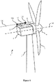
- FIG. 6 shows a wind turbine 1 according to an embodiment of the present disclosure.
- the wind turbine 1 includes a tower 2, a nacelle 3, a wheel hub 4, a generator 6 and a wind vane 11.
- the nacelle 3 is arranged on top of the tower 2, and the wheel hub 4 includes three blades 7.
- the generator 6 is disposed between the nacelle 3 and the wheel hub 4.
- the wind vane 11 is disposed on top of the nacelle 3.
- the wind vane 11 detects a wind direction, and the nacelle 3 yaws according to the wind direction to adjust a direction of wind alignment.
- the wind vane 11 is rotatably connected with a top of the nacelle 3 via a rotating shaft 13.
- the wind vane 11 is a structure in a shape of a long-strip, and has a head 113 and a tail 112.
- the wind vane 11 is rotatable with respect to the rotating shaft 13.
- the wind vane 11 has a central axis 110, and the central axis 110 and the rotating shaft 13 define an orienting plane 92 of the wind vane.
- An installation error of the wind vane refers to an angle 114 between the center axis 110 of the wind vane 11 and the center line 12 of the wind turbine, when an operator installs the wind vane by arranging the head 113 toward the wheel hub 4 and arranging the tail 112 toward the nacelle 3 and away from the wheel hub 4.
- the central axis 110 of the wind vane 11 is parallel to the center line 12 of the wind turbine under an ideal condition, and thereby the wind vane 11 can recognize a wind direction accurately. Due to an error in installation, there is the angle 114 between the center axis 110 of the wind vane 11 and the center line 12 of the wind turbine.
- the angle 114 is an absolute error angle in yawing, resulting in that the nacelle 3 cannot be aligned with an actual wind direction 13.
- the wind vane 11 may be a mechanical wind vane or an ultrasonic wind vane.
- the system includes an image collecting apparatus and a processor.
- the image collecting apparatus is detachably arranged at a head 113 of the wind vane, and is configured to acquire an image of blades of the wind turbine 7 and a generator 6.
- the processor is connected to the image collecting apparatus in communications via an image interface, and receives image data of the blades of the wind turbine and the generator collected by the image collecting apparatus.
- the image collecting apparatus may be a video camera or a camera.
- the system further includes a laser scanning apparatus.
- the laser scanning apparatus is configured to scan the wind vane 11 and a rotating shaft 13, so as to collect data of the orienting plane of the wind vane.
- the data of the orienting plane of the wind vane is determined by the laser scanning apparatus and inputted into the processor.
- the processor may be connected to the laser scanning apparatus via a scanning interface, and the scanning interface is configured to receive the data of the orienting plane of the wind vane generated by the laser scanning apparatus.
- the processor is configured to implement a flow of a method for correcting an installation error of a wind vane as shown in Figure 1 .
- Figure 1 is a flow chart of a method for correcting an installation error of a wind vane according to an embodiment of the present disclosure.
- step S101 an image of blades of the wind turbine and an outer rotor of a generator is obtained.
- the image of the blades of the wind turbine and the outer rotor of the generator may be acquired by an image collecting apparatus fixed on the wind vane.
- the image collecting apparatus may be fixed at a head of the wind vane.
- the image of the blades of the wind turbine and the outer rotor of the generator acquired by the image collecting apparatus at least includes a part of at least two blades in the blades of the wind turbine and a part of the outer rotor of the generator outer.
- the image includes two blades in the blades of the wind turbine and an upper half of the outer rotor of the generator, or a part of the two blades and a part of the outer rotor of the generator that is close to the two blades.
- step S102 a contour of the blades of the wind turbine and a contour of the outer rotor of the generator are obtained from the image of the blades of the wind turbine and the outer rotor of the generator.
- the image of the blades of the wind turbine and the outer rotor of the generator acquired by the image collecting apparatus may contain unwanted background interference information, such as sky and trees.
- Embodiments of the present disclosure focus mainly on the blades of the wind turbine and the outer rotor of the generator. Therefore, an originally acquired image of the blades of the wind turbine and the outer rotor of the generator should be processed to extract a target object that is to be measured, that is, the blades of the wind turbine and the outer rotor of the generator.
- following steps may be performed when obtaining the contour of the blades of the wind turbine and the contour of the outer rotor of the generator from the image of the blades of the wind turbine and the outer rotor of the generator.
- a grayscale image of the blades of the wind turbine and the outer rotor of the generator is obtained according to the image of the blades of the wind turbine and the outer rotor of the generator.
- Edge detection is performed on the grayscale image of the blades of the wind turbine and the outer rotor of the generator.
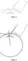
- FIG. 2 is a schematic diagram of a contour detection result of an image of blades of the wind turbine and an outer rotor of a generator acquired by a camera according to an embodiment of the present disclosure.
- Figure 2 shows a partial contour of two blades in the blades of the wind turbine, and a partial contour of the outer rotor of the generator that is close to the two blades.
- the edge detection may be performed based on a first derivative (or gradient magnitude) and a second derivative (or gradient magnitude) of grayscales of pixels in the grayscale image.
- the derivatives or the gradient magnitudes
- the derivatives are sensitive to noise, which reduces accuracy of the result of the edge detection.
- the grayscale image of the blades of the wind turbine and the outer rotor of the generator may be denoised through a Gaussian filter.
- Gradient magnitude of a grayscale of each pixel in the grayscale image is calculated after the de-noising.
- preset enhancement is performed on the grayscale of each pixel according to the gradient magnitude, so as to highlight pixels at which grayscale changes significantly in vicinity.
- an edge pixel of the blades of the wind turbine and the outer rotor of the generator is determined according to a relationship between the enhanced grayscale and a preset threshold.
- a discretized Gaussian function when denoising the grayscale image of the blades of the wind turbine and the outer rotor of the generator through the Gaussian filter, a discretized Gaussian function may be first used to generate a set of normalized Gaussian kernels, and then weighted sum is performed on all points of an image gray matrix based on a Gaussian kernel function.
- following steps may be performed when determining the edge pixel of the blades of the wind turbine and the outer rotor of the generator according to the relationship between the enhanced grayscale and the preset threshold.
- the gradient direction may be approximated to one of four candidate angles (which are 0 degree, 45 degrees, 90 degrees, and 135 degrees generally), and then non-maximum suppression is performed to pre-exclude non-edge pixels.
- the edge pixel may be determined according to a relationship between a grayscale of a pixel that is not excluded and a first threshold and a second threshold.
- a pixel with an enhanced grayscale greater than the first threshold value may be determined as the edge pixel of the blades of the wind turbine and the outer rotor of the generator.
- a pixel with an enhanced grayscale smaller than the second threshold may be determined as a non-edge pixel of the blades of the wind turbine and the outer rotor of the generator.
- a pixel that is adjacent to a determined edge pixel and with an enhanced grayscale greater than the second threshold and less than the first threshold may be determined as the edge pixel of the blades of the wind turbine and the outer rotor of the generator.
- a pixel that is not adjacent to a determined edge pixel and with an enhanced grayscale greater than the second threshold and less than the first threshold may be determined as a non-edge pixel of the blades of the wind turbine and the outer rotor of the generator.
- least square curve-fitting may be performed on the edge pixels of the blades of the wind turbine and the outer rotor of the generator that are determined in the edge detection.
- step S103 a center line of the wind turbine is calculated according to the contour of the outer rotor of the generator and a contour of two blades in the blades of the wind turbine.
- following steps may be performed when calculating the center line of the wind turbine.
- edge lines in the contour of the two blades in the wind turbine may be extended, to obtain an intersection point between the extended edge lines.
- the intersection point between the extended edge lines and a center point of the contour of the outer rotor of the generator are connected, so as to obtain the center line of the wind turbine.
- Figure 3 is a schematic diagram illustrating a center line of a wind turbine, and an intersection point between the center line of a wind turbine and a contour of an outer rotor of a generator according to an embodiment of the present disclosure.
- Figure 3 shows connecting the intersection point between extended edge lines and the center point of the contour of the outer rotor of the generator, to obtain the center line L of the wind turbine.
- Figure 9 where the edge lines in the contour of the two blades refer to two adjacent edge lines 93 and 94 in the contour of the two blades.
- step S104 an intersection point between the center line of the wind turbine and the contour of the outer rotor of the generator is obtained as a first intersection point.
- an intersection point M between the center line L of the wind turbine and the contour of the outer rotor of the generator is obtained as the first intersection point, after the center line L of the wind turbine is calculated.
- step S105 an orienting plane of the wind vane is obtained.
- following steps may be performed when obtaining the orienting plane of the wind vane.
- a result of laser orientation on the wind vane may be obtained.
- the orienting plane of the wind vane is determined according to the result of the laser orientation.
- step S106 it is determined whether the wind vane is aligned with the center line of the wind turbine, according to the center line of the wind turbine and the orienting plane of the wind vane.
- the flow goes to step S108, in a case that the wind vane is aligned with the center line of the wind turbine.
- the flow goes to step S107, in a case that the wind is not aligned with the center line of the wind turbine.
- determining whether the wind vane is aligned with the center line of the wind turbine refers to determining whether the center axis 110 of the wind vane is parallel with the center line 12 of the wind turbine.
- the determination may be based on whether the center line of the wind turbine is parallel with the orienting plane of the wind vane, when determining whether the wind vane is aligned with the center line of the wind turbine. In a case that the center line of the wind turbine is parallel with the orienting plane of the wind vane, it is determined that the wind vane is aligned with the center line of the wind turbine. In a case that the center line of the wind turbine is not parallel with the orienting plane of the wind vane, it is determined that the wind vane is not aligned with the center line of the wind turbine.
- the determination may be based on a distance between the intersection point between the center line of the wind turbine and the contour of the outer rotor of the generator and an intersection point between the orienting plane of the wind vane and the contour of the outer rotor of the generator, when determining whether the wind vane is aligned with the center line of the wind turbine. Further, it may be determined based on another method whether the wind vane is aligned with the center line of the wind turbine.
- step S107 it is determined that the wind vane is not aligned with the center line of the wind turbine, a deviation angle between the wind vane and the center line of the wind turbine is calculated based on the orienting plane of the wind vane and the first intersection point, and a direction of the wind vane is corrected according to the deviation angle between the wind vane and the center line of the wind turbine.
- following steps may be performed when calculating the deviation angle between the wind vane and the center line of the wind turbine based on the orienting plane of the wind vane and the first intersection point.
- a distance represented by each pixel in the image of the blades of the wind turbine and the outer rotor of the generator may be calculated.
- a deviation distance between the wind vane and the center line of the wind turbine, corresponding to each angle degree of the deviation angle is calculated.
- the deviation angle between the wind vane and the center line of the wind turbine is calculated, according to the distance represented by each pixel in the image of the blades of the wind turbine and the outer rotor of the generator and the deviation distance that is between the wind vane and the center line of the wind turbine and corresponds to each angle degree of the deviation angle.
- a sequence of calculating the distance represented by each pixel in the image of the blades of the wind turbine and the outer rotor of the generator and calculating the deviation distance between the wind vane and the center line of the wind turbine that corresponds to each angle degree of the deviation angle is not limited.
- the distance represented by each pixel in the image of the blades of the wind turbine and the outer rotor of the generator may be first calculated, and then the deviation distance between the wind vane and the center line of the wind turbine that corresponds to each angle degree of the deviation angle is calculated.
- the deviation distance between the wind vane and the center line of the wind turbine that corresponds to each angle degree of the deviation angle may be first calculated, and then the distance represented by each pixel in the image of the blades of the wind turbine and the outer rotor of the generator is calculated. Alternatively, the two are simultaneously calculated.
- following steps may be performed when calculating the deviation angle between the wind vane and the center line of the wind turbine based on the orienting plane of the wind vane 92 and the first intersection point.
- First, an intersection point Q between the orienting plane of the wind vane and the contour 91 of the outer rotor of the generator may be obtained as a second intersection point.
- a quantity of pixels between the first intersection point and the second intersection point are calculated in the image of the blades of the wind turbine and the outer rotor of the generator.
- a distance represented by each pixel in the image of the blades of the wind turbine and the outer rotor of the generator is calculated, according to a width of a view field of the image collecting apparatus and a quantity of pixels along a width direction of the image of the blades of the wind turbine and the outer rotor of the generator.
- a deviation distance, between the wind vane and the center line of the wind turbine, corresponding to each angle degree of the deviation angle is calculated according to a distance between the image collecting apparatus and the outer rotor of the generator, which is obtained through ultrasonic distance measurement.
- the deviation angle between the wind vane and the center line of the wind turbine is calculated, according to the distance represented by each pixel in the image of the blades of the wind turbine and the outer rotor of the generator and the deviation distance between the wind vane and the center line of the wind turbine that corresponds to each angle degree of the deviation angle.
- the image collecting apparatus is a camera.
- a width of a view field of the camera is 5m
- a quantity of pixels along a width direction of the image of the blades of the wind turbine and the outer rotor of the generator is 1920.
- the distance represented by each pixel in the image of the blades of the wind turbine and the outer rotor of the generator is equal to 500cm/1920, that is, 0.26cm.
- a distance from the camera to the outer rotor of the generator is 4m, for calculating the deviation distance between the wind vane and the center line of the wind turbine that corresponds to each angle degree of the deviation angle.
- the deviation distance between the wind vane and the center line of the wind turbine that corresponds to each angle degree of the deviation angle is equal to 400cm ⁇ tan(1°), that is, 6.98cm.
- following steps may be performed when calculating the deviation angle between the wind vane and the center line of the wind turbine.
- a quantity of pixels for each angle degree in deviation of the wind vane in the image of the blades of the wind turbine and the outer rotor of the generator may be calculated, according to the distance represented by each pixel in the image of the blades of the wind turbine and the outer rotor of the generator and the deviation distance between the wind vane and the center line of the wind turbine that corresponds to each angle degree of the deviation angle.
- the deviation angle between the wind vane and the center line of the wind turbine is calculated according to the quantity of pixels for deviation of the wind vane and the quantity of pixels for each angle degree in the deviation of the wind vane, in the image of the blades of the wind turbine and the outer rotor of the generator.
- the distance represented by each pixel in the image of the blades of the wind turbine and the outer rotor of the generator is 0.26cm
- the deviation distance between the wind vane and the center line of the wind turbine that corresponds to each angle degree of the deviation angle is 6.98cm.
- the quantity pixels for each angle degree deviation of the wind vane in the image of the blades of the wind turbine and the outer rotor of the generator is 27.
- the deviation angle between the wind vane and the center line of the wind turbine is 2°.
- step S108 the flow of correcting the installation error of the wind vane is terminated, in a case that the wind vane is aligned with the center line of the wind turbine.
- the method for collecting the installation error of the wind vane is provided according to embodiments of the present disclosure.
- the deviation angle between the wind vane and the center line of the wind turbine is calculated, and a direction of the wind vane is corrected according to the deviation angle between the wind vane and the center line of the wind turbine. Therefore, installation errors of the wind vane are accurately determined and corrected, and accuracy is improved for installation of the wind vane.
- Figure 4 is a block diagram of an apparatus for correcting an installation error of a wind vane according to an embodiment of the present disclosure.
- an apparatus for correcting an installation error of a wind vane includes: an image obtaining module 41, a contour obtaining module 42, a center line calculation module 43, a first intersection point obtaining module 44, an alignment determination module 45, and an angle correction module 46.
- the image obtaining module 41 is configured to obtain an image of blades of the wind turbine and an outer rotor of a generator.
- the image of the blades of the wind turbine and the outer rotor of the generator may be acquired by an image collecting apparatus fixed on the wind vane.
- the image collecting apparatus may be fixed at a head of the wind vane.
- the image of the blades of the wind turbine and the outer rotor of the generator acquired by the image collecting apparatus at least includes a part of at least two blades in the blades of the wind turbine and a part of the outer rotor of the generator outer.
- the image includes two blades in the blades of the wind turbine and an upper half of the outer rotor of the generator, or a part of the two blades and a part of the outer rotor of the generator that is close to the two blades.
- the contour obtaining module 42 is configured to obtain a contour of the blades of the wind turbine and a contour of the outer rotor of the generator, from the image of the blades of the wind turbine and the outer rotor of the generator.
- the image of the blades of the wind turbine and the outer rotor of the generator acquired by the image collecting apparatus may contain unwanted background interference information, such as sky and trees.
- Embodiments of the present disclosure focus mainly on the blades of the wind turbine and the outer rotor of the generator. Therefore, an originally acquired image of the blades of the wind turbine and the outer rotor of the generator should be processed to extract a target object that is to be measured, that is, the blades of the wind turbine and the outer rotor of the generator.
- the contour obtaining module 42 is configured to perform following operations.
- a grayscale image of the blades of the wind turbine and the outer rotor of the generator is obtained according to the image of the blades of the wind turbine and the outer rotor of the generator.
- Edge detection is performed on the grayscale image of the blades of the wind turbine and the outer rotor of the generator.
- Contour detection is performed on the grayscale image of the blades of the wind turbine and the outer rotor of the generator, according to a result of the edge detection.
- the edge detection may be performed based on a first derivative (or gradient magnitude) and a second derivative (or gradient magnitude) of grayscales of pixels in the grayscale image.
- the derivatives or the gradient magnitudes
- the derivatives are sensitive to noise, which reduces accuracy of the result of the edge detection.
- the contour obtaining module 42 is configured to perform following operations, when performing edge detection on the grayscale image of the blades of the wind turbine and the outer rotor of the generator.
- the grayscale image of the blades of the wind turbine and the outer rotor of the generator is denoised through a Gaussian filter.
- gradient magnitude of a grayscale of each pixel in the grayscale image is calculated after the de-noising.
- Preset enhancement is performed on the grayscale of each pixel according to the gradient magnitude.
- an edge pixel of the blades of the wind turbine and the outer rotor of the generator is determined according to a relationship between the enhanced grayscale and a preset threshold.
- the contour obtaining module 42 is configured to perform following operations, when denoising the grayscale image of the blades of the wind turbine and the outer rotor of the generator through the Gaussian filter. First a discretized Gaussian function is used to generate a set of normalized Gaussian kernels, and then weighted sum is performed on all points of an image gray matrix based on a Gaussian kernel function.
- the contour obtaining module 42 is configured to perform following operations, when determining the edge pixel of the blades of the wind turbine and the outer rotor of the generator according to the relationship between the enhanced grayscale and the preset threshold.
- the gradient direction may be approximated to one of four candidate angles (which are 0 degree, 45 degrees, 90 degrees, and 135 degrees generally), and then non-maximum suppression is performed to pre-exclude non-edge pixels.
- the edge pixel may be determined according to a relationship between a grayscale of a pixel that is not excluded and a first threshold and a second threshold.
- the contour obtaining module 42 is configured to perform following operations.
- a pixel with an enhanced grayscale greater than the first threshold value is determined to be the edge pixel of the blades of the wind turbine and the outer rotor of the generator.
- a pixel with an enhanced grayscale smaller than the second threshold is determined not to be the edge pixel of the blades of the wind turbine and the outer rotor of the generator.
- a pixel that is adjacent to a determined edge pixel and with an enhanced grayscale greater than the second threshold and less than the first threshold is determined to be the edge pixel of the blades of the wind turbine and the outer rotor of the generator.
- a pixel that is not adjacent to a determined edge pixel and with an enhanced grayscale greater than the second threshold and less than the first threshold is determined not to be the edge pixel of the blades of the wind turbine and the outer rotor of the generator.
- the contour obtaining module 42 is configured to perform a following operation, when performing the contour detection on the grayscale image of the blades of the wind turbine and the outer rotor of the generator according to the result of the edge detection. Least square curve-fitting is performed on the edge pixels of the blades of the wind turbine and the outer rotor of the generator that are determined in the edge detection.
- the center line calculation module 43 is configured to calculate a center line of the wind turbine, according to the contour of the outer rotor of the generator and a contour of two blades in the blades of the wind turbine.
- the center line calculation module 43 is configured to perform following steps, when calculating the center line of the wind turbine. First, edge lines in the contour of the two blades in the wind turbine may be extended, to obtain an intersection point between the extended edge lines. Then, the intersection point between the extended edge lines and a center point of the contour of the outer rotor of the generator are connected, so as to obtain the center line of the wind turbine.
- the first intersection point obtaining module 44 is configured to obtain an intersection point between the center line of the wind turbine and the contour of the outer rotor of the generator, as a first intersection point.
- the alignment determination module 45 is configured to obtain an orienting plane of the wind vane, and determine whether the wind vane is aligned with the center line of the wind turbine according to the center line of the wind turbine and the orienting plane of the wind vane.
- the alignment determination module 45 is configured to perform following operations, when obtaining the orienting plane of the wind vane. First, a result of laser orientation on the wind vane may be obtained. Then, the orienting plane of the wind vane is determined according to the result of the laser orientation.
- the alignment determination module 45 may determine based on whether the center line of the wind turbine is parallel with the orienting plane of the wind vane, when determining whether the wind vane is aligned with the center line of the wind turbine. In a case that the center line of the wind turbine is parallel with the orienting plane of the wind vane, it is determined that the wind vane is aligned with the center line of the wind turbine. In a case that the center line of the wind turbine is not parallel with the orienting plane of the wind vane, it is determined that the wind vane is not aligned with the center line of the wind turbine.
- the alignment determination module 45 may determine based on a distance between the intersection point between the center line of the wind turbine and the contour of the outer rotor of the generator and an intersection point between the orienting plane of the wind vane and the contour of the outer rotor of the generator, when determining whether the wind vane is aligned with the center line of the wind turbine. Further, it may be determined based on another method whether the wind vane is aligned with the center line of the wind turbine.
- the angle correction module 46 is configured to determine that the wind vane is not aligned with the center line of the wind turbine, calculate a deviation angle between the wind vane and the center line of the wind turbine based on the orienting plane of the wind vane and the first intersection point, and correct a direction of the wind vane according to the deviation angle between the wind vane and the center line of the wind turbine.
- the angle correction module 46 is configured to perform following operations, when calculating the deviation angle between the wind vane and the center line of the wind turbine based on the orienting plane of the wind vane and the first intersection point. First, a distance represented by each pixel in the image of the blades of the wind turbine and the outer rotor of the generator is calculated. Then, a deviation distance between the wind vane and the center line of the wind turbine, corresponding to each angle degree of the deviation angle, is calculated.
- the deviation angle between the wind vane and the center line of the wind turbine is calculated, according to the distance represented by each pixel in the image of the blades of the wind turbine and the outer rotor of the generator and the deviation distance that is between the wind vane and the center line of the wind turbine and corresponds to each angle degree of the deviation angle.
- a sequence of calculating the distance represented by each pixel in the image of the blades of the wind turbine and the outer rotor of the generator and calculating the deviation distance between the wind vane and the center line of the wind turbine that corresponds to each angle degree of the deviation angle is not limited for the angle correction module 46.
- the distance represented by each pixel in the image of the blades of the wind turbine and the outer rotor of the generator may be first calculated, and then the deviation distance between the wind vane and the center line of the wind turbine that corresponds to each angle degree of the deviation angle is calculated.
- the deviation distance between the wind vane and the center line of the wind turbine that corresponds to each angle degree of the deviation angle may be first calculated, and then the distance represented by each pixel in the image of the blades of the wind turbine and the outer rotor of the generator is calculated. Alternatively, the two are simultaneously calculated.
- the angle correction module 46 is configured to perform following operations, when calculating the deviation angle between the wind vane and the center line of the wind turbine based on the orienting plane of the wind vane and the first intersection point. First, an intersection point between the orienting plane of the wind vane and the contour of the outer rotor of the generator is obtained as a second intersection point. Then, a quantity of pixels between the first intersection point and the second intersection point are calculated in the image of the blades of the wind turbine and the outer rotor of the generator.
- a distance represented by each pixel in the image of the blades of the wind turbine and the outer rotor of the generator is calculated, according to a width of a view field of the image collecting apparatus and a quantity of pixels along a width direction of the image of the blades of the wind turbine and the outer rotor of the generator.
- a deviation distance, between the wind vane and the center line of the wind turbine, corresponding to each angle degree of the deviation angle is calculated according to a distance between the image collecting apparatus and the outer rotor of the generator, which is obtained through ultrasonic distance measurement.
- the deviation angle between the wind vane and the center line of the wind turbine is calculated, according to the distance represented by each pixel in the image of the blades of the wind turbine and the outer rotor of the generator and the deviation distance between the wind vane and the center line of the wind turbine that corresponds to each angle degree of the deviation angle.
- the angle correction module 46 is configured to perform following operations, when calculating the deviation angle between the wind vane and the center line of the wind turbine. First, a quantity of pixels for each angle degree in deviation of the wind vane in the image of the blades of the wind turbine and the outer rotor of the generator may be calculated, according to the distance represented by each pixel in the image of the blades of the wind turbine and the outer rotor of the generator and the deviation distance between the wind vane and the center line of the wind turbine that corresponds to each angle degree of the deviation angle.
- the deviation angle between the wind vane and the center line of the wind turbine is calculated according to the quantity of pixels for deviation of the wind vane and the quantity of pixels for each angle degree in the deviation of the wind vane, in the image of the blades of the wind turbine and the outer rotor of the generator.
- correcting the installation error of the wind vane is terminated, in a case that the wind vane is aligned with the center line of the wind turbine.
- the apparatus for collecting the installation error of the wind vane is provided according to embodiments of the present disclosure.
- the image of the blades of the wind turbine and the outer rotor of the generator is obtained.
- the deviation angle between the wind vane and the center line of the wind turbine is calculated, and a direction of the wind vane is corrected according to the deviation angle between the wind vane and the center line of the wind turbine. Therefore, installation errors of the wind vane are accurately determined and corrected, and accuracy is improved for installation of the wind vane.
- a computer-readable storage medium is further provided according to an embodiment of the present disclosure.
- the computer-readable storage medium stores a computer program.
- the computer program when executed implements the method for correcting the installation error of the wind vane according to embodiments of the present disclosure.
- the program when executed may implement following steps.
- An image, of blades of a wind turbine and an outer rotor of a generator is obtained.
- a contour of the blades of the wind turbine and a contour of the outer rotor of the generator are obtained from the image of the blades of the wind turbine and the outer rotor of the generator.
- a center line of the wind turbine is calculated according to the contour of the outer rotor of the generator and a contour of two blades in the blades of the wind turbine.
- An intersection point between the center line of the wind turbine and the contour of the outer rotor of the generator is obtained as a first intersection point.
- An orienting plane of the wind vane is obtained, and it is determined whether the wind vane is aligned with the center line of the wind turbine, according to the center line of the wind turbine and the orienting plane of the wind vane.
- a deviation angle between the wind vane and the center line of the wind turbine is calculated based on the orienting plane of the wind vane and the first intersection point, and a direction of the wind vane is corrected according to the deviation angle between the wind vane and the center line of the wind turbine.
- Figure 5 is a block diagram of a computing apparatus according to an embodiment of the present disclosure.
- a computing apparatus 5 includes: a memory 51, a processor 52 and a computer program.
- the computer program is stored in the memory and executable by the processor.
- the processor when executing the computer program implements the method for correcting the installation error of the wind vane according to embodiments of the present disclosure.
- the processor is configured to execute the program including following steps.
- An image, of blades of a wind turbine and an outer rotor of a generator is obtained.
- a contour of the blades of the wind turbine and a contour of the outer rotor of the generator are obtained from the image of the blades of the wind turbine and the outer rotor of the generator.
- a center line of the wind turbine is calculated according to the contour of the outer rotor of the generator and a contour of two blades in the blades of the wind turbine.
- An intersection point between the center line of the wind turbine and the contour of the outer rotor of the generator is obtained as a first intersection point.
- An orienting plane of the wind vane is obtained, and it is determined whether the wind vane is aligned with the center line of the wind turbine, according to the center line of the wind turbine and the orienting plane of the wind vane.
- a deviation angle between the wind vane and the center line of the wind turbine is calculated based on the orienting plane of the wind vane and the first intersection point, and a direction of the wind vane is corrected according to the deviation angle between the wind vane and the center line of the wind turbine.
- the apparatus for correcting the installation error of the wind vane as shown in Figure 4 and the modules thereof may be software, hardware, firmware, or any combination thereof, for performing specific functions.
- the method and the apparatus for collecting the installation error of the wind vane are provided according to embodiments of the present disclosure.
- the image of the blades of the wind turbine and the outer rotor of the generator is obtained. It is determined whether the wind vane is aligned with the center line of the wind turbine, according to a relationship between the center line of the wind turbine and the orienting plane of the wind vane in the image. In a case that the wind vane is not aligned with the center line of the wind turbine, the deviation angle between the wind vane and the center line of the wind turbine is calculated, and a direction of the wind vane is corrected according to the deviation angle between the wind vane and the center line of the wind turbine. Therefore, installation errors of the wind vane are accurately determined and corrected, and accuracy is improved for installation of the wind vane.
Landscapes
- Engineering & Computer Science (AREA)
- Physics & Mathematics (AREA)
- General Physics & Mathematics (AREA)
- Theoretical Computer Science (AREA)
- Computer Vision & Pattern Recognition (AREA)
- Sustainable Energy (AREA)
- Mechanical Engineering (AREA)
- General Engineering & Computer Science (AREA)
- Combustion & Propulsion (AREA)
- Chemical & Material Sciences (AREA)
- Life Sciences & Earth Sciences (AREA)
- Sustainable Development (AREA)
- Quality & Reliability (AREA)
- Aviation & Aerospace Engineering (AREA)
- Wind Motors (AREA)
Description
- The present disclosure relates to the field of wind power generation, and in particular, to a method, an apparatus and a system for correcting an installation error of a wind vane.
- A yaw system is an important part of a wind turbine. The yaw system is capable to achieve fast and smooth wind alignment when the wind direction changes, so that a wind wheel can acquire maximum wind energy. A wind vane serves as a front-end input in a yaw strategy for wind alignment. A deviation in detecting the wind direction by the wind vane would result in a power loss of the wind turbine and an increase in a load of the wind turbine.
- At present, the wind vane of the wind turbine is generally installed on top of a nacelle, and the installation is manually performed. A direction of the wind vane is adjusted by a staff, in order to align a marking "S" on a rotating shaft of the wind vane with a head of the wind turbine, or align a marking "N" with a tail of the wind turbine. Then, the rotating shaft of the wind vane is fixed on top of the nacelle. In such case, there is an absolute error angle between the direction of the wind vane and a center line of the wind turbine, and the wind wheel is not exactly aligned with the wind direction due to the absolute error angle.
-
CN207064155U discloses an installation angle measuring device and system of wind vane. The wind vane is installed in wind generating set cabin housing top, and wherein, the installation angle measuring device of wind vane includes: the bearing is fixed in on the rotor plane near the cabin side, angle measurement element sets up in the bearing, and angle measurement element includes portion of measurationing and pivot, and the portion of measurationing upwards centers on the pivot extension in the week of pivot and distributes, can obtain the pivot for a pivoted angle of measurationing through the portion of measurationing, adapting unit, including two tip, one of them tip is connected with the pivot, and another tip is connected with the wind vane, and adapting unit is used for driving the pivot and rotates along with the wind vane. The utility model discloses the installation angle measuring device of wind vane can detect the mounted position of wind vane to whether the mountedposition of supplementary snap judgments wind vane is in the tram. - "A Computer Vision Approach for Autonomous Wind Turbine Inspection using a Multicopter" discloses the mission of autonomous inspection of a wind turbine using a multicopter. Emphasis was placed on recognition and tracking using image processing methods. The Hough line transform was used to extract features of the wind turbine. Hub position was estimated by an algorithm tailored to identify the three-point star resemblance and was tracked by utilizing the Kalman filter. Distance and yaw orientation of the wind turbine were estimated using the pinhole camera model and coordinate transformations. Restricting computational demand was a goal in the program design. Experiments showed accurate position tracking at long range, but with deteriorating performance as range was decreased. Lack of distinctive measurable lengths in the image caused inaccuracy in estimation of distance and yaw orientation. Execution frequency of below 7 Hz was achieved on a single-board computer which was found to be sufficient for reliable control in flight.
- A method, an apparatus and a system for correcting an installation error of a wind vane is provided according to embodiments of the present disclosure, so as to achieve automatic correction of installation errors of wind vanes and improve accuracy of installation of wind vanes.
- A method for correcting an installation error of a wind vane of a wind turbine according to
claim 1 is provided according to an embodiment of the present disclosure. - In an optional embodiment, obtaining the contour of the blades of the wind turbine and the contour of the outer rotor of the generator from the image of the blades of the wind turbine and the outer rotor of the generator includes: obtaining a grayscale image of the blades of the wind turbine and the outer rotor of the generator, according to the image of the blades of the wind turbine and the outer rotor of the generator; performing edge detection on the grayscale image; and performing contour detection on the grayscale image, according to a result of the edge detection.
- In an optional embodiment, performing the edge detection on the grayscale image of the blades of the wind turbine and the outer rotor of the generator includes: denoising the grayscale image of the blades of the wind turbine and the outer rotor of the generator, through a Gaussian filter; calculating gradient magnitude of a grayscale of each pixel in the grayscale image after the de-noising; performing preset enhancement on the grayscale of each pixel, according to the gradient magnitude; and determining an edge pixel of the blades of the wind turbine and the outer rotor of the generator, according to a relationship between the enhanced grayscale and a preset threshold.
- In an optional embodiment, obtaining the orienting plane of the wind vane includes: obtaining a result of laser orientation on the wind vane; and determining the orienting plane of the wind vane according to the result of the laser orientation.
- In an optional embodiment, calculating the deviation angle between the wind vane and the center line of the wind turbine based on the orienting plane of the wind vane and the first intersection point includes: obtaining an intersection point between the orienting plane of the wind vane and the contour of the outer rotor of the generator, as a second intersection; calculating a quantity of pixels, which are between the first intersection point and the second intersection point, in the image of the blades of the wind turbine and the outer rotor of the generator, where the image is obtained by an image collecting apparatus fixed on the wind vane, and the image collecting apparatus is fixed at a head of the wind vane; calculating a distance represented by each pixel in the image, according to a width of a view field of the image collecting apparatus and a quantity of pixels along a width direction of the image; calculating a deviation distance, between the wind vane and the center line of the wind turbine, corresponding to each angle degree of the deviation angle, according to a distance between the image collecting apparatus and the outer rotor of the generator, where the distance between the image collecting apparatus and the outer rotor of the generator is obtained through ultrasonic distance measurement; and calculating the deviation angle between the wind vane and the center line of the wind turbine, according to the distance represented by each pixel in the image and the deviation distance corresponding to each angle degree.
- A apparatus for correcting an installation error of a wind vane of a wind turbine according to
claim 6 is provided according to an embodiment of the present disclosure. - In an optional embodiment, the contour obtaining module is configured to: obtain a grayscale image of the blades of the wind turbine and the outer rotor of the generator, according to the image of the blades of the wind turbine and the outer rotor of the generator; perform edge detection on the grayscale image; and perform contour detection on the grayscale image, according to a result of the edge detection.
- In an optional embodiment, the contour obtaining module is configured to: denoise the grayscale image of the blades of the wind turbine and the outer rotor of the generator, through a Gaussian filter; calculate gradient magnitude of a grayscale of each pixel in the grayscale image after the de-noising; perform preset enhancement on the grayscale of each pixel, according to the gradient magnitude; and determine an edge pixel of the blades of the wind turbine and the outer rotor of the generator, according to a relationship between the enhanced grayscale and a preset threshold.
- In an optional embodiment, the alignment determination module is configured to: obtain a result of laser orientation on the wind vane, and determine the orienting plane of the wind vane according to the result of the laser orientation.
- In an optional embodiment, the angle correction module is configured to: obtain an intersection point between the orienting plane of the wind vane and the contour of the outer rotor of the generator, as a second intersection; calculate a quantity of pixels, which are between the first intersection point and the second intersection point, in the image of the blades of the wind turbine and the outer rotor of the generator, where the image is obtained by an image collecting apparatus fixed on the wind vane, and the image collecting apparatus is fixed at a head of the wind vane; calculate a distance represented by each pixel in the image, according to a width of a view field of the image collecting apparatus and a quantity of pixels along a width direction of the image; calculate a deviation distance, between the wind vane and the center line of the wind turbine, corresponding to each angle degree of the deviation angle, according to a distance between the image collecting apparatus and the outer rotor of the generator, where the distance between the image collecting apparatus and the outer rotor of the generator is obtained through ultrasonic distance measurement; and calculate the deviation angle between the wind vane and the center line of the wind turbine, according to the distance represented by each pixel in the image and the deviation distance corresponding to each angle degree.
- A computer-readable storage medium according to
claim 7 is provided according to an embodiment of the present disclosure. - A computing apparatus according to claim 8 is provided according to an embodiment of the present disclosure.
- A system for correcting an installation error of a wind vane of a wind turbine according to claim 9 is provided according to an embodiment of the present disclosure.
- In an optional embodiment, the processor is further configured to: obtain a grayscale image of the blades of the wind turbine and the outer rotor of the generator, according to the image of the blades of the wind turbine and the outer rotor of the generator; perform edge detection on the grayscale image; and perform contour detection on the grayscale image, according to a result of the edge detection.
- In an optional embodiment, the processor is further configured to: denoise the grayscale image of the blades of the wind turbine and the outer rotor of the generator, through a Gaussian filter; calculate gradient magnitude of a grayscale of each pixel in the grayscale image after the de-noising; perform preset enhancement on the grayscale of each pixel, according to the gradient magnitude; and determine an edge pixel of the blades of the wind turbine and the outer rotor of the generator, according to a relationship between the enhanced grayscale and a preset threshold.
- In an optional embodiment, the system further includes a laser scanning apparatus, wherein the laser scanning apparatus is configured to: scan the wind vane and a rotating shaft, and collect data of the orienting plane of the wind vane; where the processor is further configured to: obtain a result of laser orientation on the wind vane, and determine the orienting plane of the wind vane according to the result of the laser orientation.
- In an optional embodiment, the processor is further configured to: obtain an intersection point between the orienting plane of the wind vane and the contour of the outer rotor of the generator, as a second intersection; calculate a quantity of pixels, which are between the first intersection point and the second intersection point, in the image of the blades of the wind turbine and the outer rotor of the generator, where the image is obtained by the image collecting apparatus fixed on the wind vane; calculate a distance represented by each pixel in the image, according to a width of a view field of the image collecting apparatus and a quantity of pixels along a width direction of the image; calculate a deviation distance, between the wind vane and the center line of the wind turbine, corresponding to each angle degree of the deviation angle, according to a distance between the image collecting apparatus and the outer rotor of the generator, where the distance between the image collecting apparatus and the outer rotor of the generator is obtained through ultrasonic distance measurement; and calculate the deviation angle between the wind vane and the center line of the wind turbine, according to the distance represented by each pixel in the image and the deviation distance corresponding to each angle degree.
- The method, the apparatus, and the system for collecting the installation error of the wind vane are provided according to embodiments of the present disclosure. The image of the blades of the wind turbine and the outer rotor of the generator is obtained. It is determined whether the wind vane is aligned with the center line of the wind turbine, according to a relationship between the center line of the wind turbine and the orienting plane of the wind vane in the image. In a case that the wind vane is not aligned with the center line of the wind turbine, the deviation angle between the wind vane and the center line of the wind turbine is calculated, and a direction of the wind vane is corrected according to the deviation angle between the wind vane and the center line of the wind turbine. Therefore, installation errors of the wind vane are accurately determined and corrected, and accuracy is improved for installation of the wind vane.
- Hereinafter embodiments are described in conjunction with drawings, such that the above and other objectives and features of embodiments of the present disclosure are clearer.
-
Figure 1 is a flow chart of a method for correcting an installation error of a wind vane according to an embodiment of the present disclosure; -
Figure 2 is a schematic diagram of a contour detection result of an image of blades of the wind turbine and an outer rotor of a generator acquired by a camera according to an embodiment of the present disclosure; -
Figure 3 is a schematic diagram of a center line of a wind turbine, and an intersection point between the center line of a wind turbine and a contour of an outer rotor of a generator according to an embodiment of the present disclosure; -
Figure 4 is a block diagram of an apparatus for correcting an installation error of a wind vane according to an embodiment of the present disclosure; -
Figure 5 is a block diagram of a computing apparatus according to an embodiment of the present disclosure; -
Figure 6 is a schematic diagram of a wind turbine according to an embodiment of the present disclosure; -
Figure 7 is a top view of a wind turbine according to an embodiment of the present disclosure; -
Figure 8 is a schematic diagram of a system for correcting an installation error of a wind vane according to an embodiment of the present disclosure; and -
Figure 9 is a schematic diagram illustrating an orienting plane of the wind vane according to an embodiment of the present disclosure. - Hereinafter detailed reference is made to embodiments of the present disclosure, examples of which are shown in the drawings. Same reference numerals refer to same components. Hereinafter embodiments are described in conjunction with the drawings to explain the present disclosure.
- Embodiments of the present disclosure are applicable to the field of wind power generation, and in particular, to an apparatus or a system for correcting an installation error of a wind vane.
-
Figure 6 shows awind turbine 1 according to an embodiment of the present disclosure. Thewind turbine 1 includes atower 2, anacelle 3, awheel hub 4, agenerator 6 and awind vane 11. Thenacelle 3 is arranged on top of thetower 2, and thewheel hub 4 includes threeblades 7. Thegenerator 6 is disposed between thenacelle 3 and thewheel hub 4. Thewind vane 11 is disposed on top of thenacelle 3. Thewind vane 11 detects a wind direction, and thenacelle 3 yaws according to the wind direction to adjust a direction of wind alignment. There is acenter line 12 of thewind turbine 1. - The
wind vane 11 is rotatably connected with a top of thenacelle 3 via a rotatingshaft 13. Thewind vane 11 is a structure in a shape of a long-strip, and has ahead 113 and atail 112. Thewind vane 11 is rotatable with respect to therotating shaft 13. Thewind vane 11 has acentral axis 110, and thecentral axis 110 and therotating shaft 13 define an orientingplane 92 of the wind vane. - An installation error of the wind vane refers to an
angle 114 between thecenter axis 110 of thewind vane 11 and thecenter line 12 of the wind turbine, when an operator installs the wind vane by arranging thehead 113 toward thewheel hub 4 and arranging thetail 112 toward thenacelle 3 and away from thewheel hub 4. - As shown in
Figure 7 , thecentral axis 110 of thewind vane 11 is parallel to thecenter line 12 of the wind turbine under an ideal condition, and thereby thewind vane 11 can recognize a wind direction accurately. Due to an error in installation, there is theangle 114 between thecenter axis 110 of thewind vane 11 and thecenter line 12 of the wind turbine. Theangle 114 is an absolute error angle in yawing, resulting in that thenacelle 3 cannot be aligned with anactual wind direction 13. - The
wind vane 11 may be a mechanical wind vane or an ultrasonic wind vane. - A system for correcting an installation error of a wind vane of a wind turbine is provided according to an embodiment of the present disclosure. Referring to
Figure 8 , the system includes an image collecting apparatus and a processor. The image collecting apparatus is detachably arranged at ahead 113 of the wind vane, and is configured to acquire an image of blades of thewind turbine 7 and agenerator 6. The processor is connected to the image collecting apparatus in communications via an image interface, and receives image data of the blades of the wind turbine and the generator collected by the image collecting apparatus. - The image collecting apparatus may be a video camera or a camera.
- The system further includes a laser scanning apparatus. The laser scanning apparatus is configured to scan the
wind vane 11 and arotating shaft 13, so as to collect data of the orienting plane of the wind vane. The data of the orienting plane of the wind vane is determined by the laser scanning apparatus and inputted into the processor. The processor may be connected to the laser scanning apparatus via a scanning interface, and the scanning interface is configured to receive the data of the orienting plane of the wind vane generated by the laser scanning apparatus. - The processor is configured to implement a flow of a method for correcting an installation error of a wind vane as shown in
Figure 1 . -
Figure 1 is a flow chart of a method for correcting an installation error of a wind vane according to an embodiment of the present disclosure. - Reference is made to
Figure 1 . In step S101, an image of blades of the wind turbine and an outer rotor of a generator is obtained. - In an embodiment of the present disclosure, the image of the blades of the wind turbine and the outer rotor of the generator may be acquired by an image collecting apparatus fixed on the wind vane. The image collecting apparatus may be fixed at a head of the wind vane. The image of the blades of the wind turbine and the outer rotor of the generator acquired by the image collecting apparatus at least includes a part of at least two blades in the blades of the wind turbine and a part of the outer rotor of the generator outer. For example, the image includes two blades in the blades of the wind turbine and an upper half of the outer rotor of the generator, or a part of the two blades and a part of the outer rotor of the generator that is close to the two blades.
- In step S102, a contour of the blades of the wind turbine and a contour of the outer rotor of the generator are obtained from the image of the blades of the wind turbine and the outer rotor of the generator.
- The image of the blades of the wind turbine and the outer rotor of the generator acquired by the image collecting apparatus may contain unwanted background interference information, such as sky and trees. Embodiments of the present disclosure focus mainly on the blades of the wind turbine and the outer rotor of the generator. Therefore, an originally acquired image of the blades of the wind turbine and the outer rotor of the generator should be processed to extract a target object that is to be measured, that is, the blades of the wind turbine and the outer rotor of the generator.
- In an embodiment of the present disclosure, following steps may be performed when obtaining the contour of the blades of the wind turbine and the contour of the outer rotor of the generator from the image of the blades of the wind turbine and the outer rotor of the generator. First, a grayscale image of the blades of the wind turbine and the outer rotor of the generator is obtained according to the image of the blades of the wind turbine and the outer rotor of the generator. Edge detection is performed on the grayscale image of the blades of the wind turbine and the outer rotor of the generator. Then, contour detection is performed on the grayscale image of the blades of the wind turbine and the outer rotor of the generator, according to a result of the edge detection, so as to obtain the contour of the blades of the wind turbine and the contour of the outer rotor of the generator. Reference is made to
Figure 2 , which is a schematic diagram of a contour detection result of an image of blades of the wind turbine and an outer rotor of a generator acquired by a camera according to an embodiment of the present disclosure.Figure 2 shows a partial contour of two blades in the blades of the wind turbine, and a partial contour of the outer rotor of the generator that is close to the two blades. - In an embodiment of the present disclosure, the edge detection may be performed based on a first derivative (or gradient magnitude) and a second derivative (or gradient magnitude) of grayscales of pixels in the grayscale image. Generally, the derivatives (or the gradient magnitudes) are sensitive to noise, which reduces accuracy of the result of the edge detection.
- Therefore, following steps may be performed in an embodiment of the present disclosure, when performing edge detection on the grayscale image of the blades of the wind turbine and the outer rotor of the generator. First, the grayscale image of the blades of the wind turbine and the outer rotor of the generator may be denoised through a Gaussian filter. Gradient magnitude of a grayscale of each pixel in the grayscale image is calculated after the de-noising. Then, preset enhancement is performed on the grayscale of each pixel according to the gradient magnitude, so as to highlight pixels at which grayscale changes significantly in vicinity. Finally, an edge pixel of the blades of the wind turbine and the outer rotor of the generator is determined according to a relationship between the enhanced grayscale and a preset threshold.
- In an embodiment of the present disclosure, when denoising the grayscale image of the blades of the wind turbine and the outer rotor of the generator through the Gaussian filter, a discretized Gaussian function may be first used to generate a set of normalized Gaussian kernels, and then weighted sum is performed on all points of an image gray matrix based on a Gaussian kernel function.
- In an embodiment of the present disclosure, when calculating the gradient magnitude of the grayscale of each pixel in the grayscale image, the gradient magnitude and a gradient direction may be calculated according to following equations:
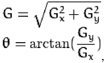
- In an embodiment of the present disclosure, following steps may be performed when determining the edge pixel of the blades of the wind turbine and the outer rotor of the generator according to the relationship between the enhanced grayscale and the preset threshold. First, the gradient direction may be approximated to one of four candidate angles (which are 0 degree, 45 degrees, 90 degrees, and 135 degrees generally), and then non-maximum suppression is performed to pre-exclude non-edge pixels. Afterwards, the edge pixel may be determined according to a relationship between a grayscale of a pixel that is not excluded and a first threshold and a second threshold.
- In an embodiment of the present disclosure, a pixel with an enhanced grayscale greater than the first threshold value may be determined as the edge pixel of the blades of the wind turbine and the outer rotor of the generator. A pixel with an enhanced grayscale smaller than the second threshold may be determined as a non-edge pixel of the blades of the wind turbine and the outer rotor of the generator. A pixel that is adjacent to a determined edge pixel and with an enhanced grayscale greater than the second threshold and less than the first threshold may be determined as the edge pixel of the blades of the wind turbine and the outer rotor of the generator. A pixel that is not adjacent to a determined edge pixel and with an enhanced grayscale greater than the second threshold and less than the first threshold may be determined as a non-edge pixel of the blades of the wind turbine and the outer rotor of the generator.
- In an embodiment of the present disclosure, when performing the contour detection on the grayscale image of the blades of the wind turbine and the outer rotor of the generator according to the result of the edge detection, least square curve-fitting may be performed on the edge pixels of the blades of the wind turbine and the outer rotor of the generator that are determined in the edge detection.
- In step S103, a center line of the wind turbine is calculated according to the contour of the outer rotor of the generator and a contour of two blades in the blades of the wind turbine.
- In an embodiment of the present disclosure, following steps may be performed when calculating the center line of the wind turbine. First, edge lines in the contour of the two blades in the wind turbine may be extended, to obtain an intersection point between the extended edge lines. Then, the intersection point between the extended edge lines and a center point of the contour of the outer rotor of the generator are connected, so as to obtain the center line of the wind turbine. Reference is made to
Figure 3 . -
Figure 3 is a schematic diagram illustrating a center line of a wind turbine, and an intersection point between the center line of a wind turbine and a contour of an outer rotor of a generator according to an embodiment of the present disclosure.Figure 3 shows connecting the intersection point between extended edge lines and the center point of the contour of the outer rotor of the generator, to obtain the center line L of the wind turbine. Reference is made toFigure 9 , where the edge lines in the contour of the two blades refer to twoadjacent edge lines - In step S104, an intersection point between the center line of the wind turbine and the contour of the outer rotor of the generator is obtained as a first intersection point.
- Referring to
Figure 3 , an intersection point M between the center line L of the wind turbine and the contour of the outer rotor of the generator is obtained as the first intersection point, after the center line L of the wind turbine is calculated. - In step S105, an orienting plane of the wind vane is obtained.
- In an embodiment of the present disclosure, following steps may be performed when obtaining the orienting plane of the wind vane. First, a result of laser orientation on the wind vane may be obtained. Then, the orienting plane of the wind vane is determined according to the result of the laser orientation.
- In step S106, it is determined whether the wind vane is aligned with the center line of the wind turbine, according to the center line of the wind turbine and the orienting plane of the wind vane. The flow goes to step S108, in a case that the wind vane is aligned with the center line of the wind turbine. The flow goes to step S107, in a case that the wind is not aligned with the center line of the wind turbine.
- Hereinafter determining whether the wind vane is aligned with the center line of the wind turbine refers to determining whether the
center axis 110 of the wind vane is parallel with thecenter line 12 of the wind turbine. - In an embodiment of the present disclosure, the determination may be based on whether the center line of the wind turbine is parallel with the orienting plane of the wind vane, when determining whether the wind vane is aligned with the center line of the wind turbine. In a case that the center line of the wind turbine is parallel with the orienting plane of the wind vane, it is determined that the wind vane is aligned with the center line of the wind turbine. In a case that the center line of the wind turbine is not parallel with the orienting plane of the wind vane, it is determined that the wind vane is not aligned with the center line of the wind turbine. In addition, the determination may be based on a distance between the intersection point between the center line of the wind turbine and the contour of the outer rotor of the generator and an intersection point between the orienting plane of the wind vane and the contour of the outer rotor of the generator, when determining whether the wind vane is aligned with the center line of the wind turbine. Further, it may be determined based on another method whether the wind vane is aligned with the center line of the wind turbine.
- In step S107, it is determined that the wind vane is not aligned with the center line of the wind turbine, a deviation angle between the wind vane and the center line of the wind turbine is calculated based on the orienting plane of the wind vane and the first intersection point, and a direction of the wind vane is corrected according to the deviation angle between the wind vane and the center line of the wind turbine.
- In an embodiment of the present disclosure, following steps may be performed when calculating the deviation angle between the wind vane and the center line of the wind turbine based on the orienting plane of the wind vane and the first intersection point. First, a distance represented by each pixel in the image of the blades of the wind turbine and the outer rotor of the generator may be calculated. Then, a deviation distance between the wind vane and the center line of the wind turbine, corresponding to each angle degree of the deviation angle, is calculated. Finally, the deviation angle between the wind vane and the center line of the wind turbine is calculated, according to the distance represented by each pixel in the image of the blades of the wind turbine and the outer rotor of the generator and the deviation distance that is between the wind vane and the center line of the wind turbine and corresponds to each angle degree of the deviation angle.
- In an embodiment of the present disclosure, a sequence of calculating the distance represented by each pixel in the image of the blades of the wind turbine and the outer rotor of the generator and calculating the deviation distance between the wind vane and the center line of the wind turbine that corresponds to each angle degree of the deviation angle is not limited. As described above, the distance represented by each pixel in the image of the blades of the wind turbine and the outer rotor of the generator may be first calculated, and then the deviation distance between the wind vane and the center line of the wind turbine that corresponds to each angle degree of the deviation angle is calculated. Or, the deviation distance between the wind vane and the center line of the wind turbine that corresponds to each angle degree of the deviation angle may be first calculated, and then the distance represented by each pixel in the image of the blades of the wind turbine and the outer rotor of the generator is calculated. Alternatively, the two are simultaneously calculated.
- Reference is made to
Figure 9 . In an embodiment of the present disclosure, following steps may be performed when calculating the deviation angle between the wind vane and the center line of the wind turbine based on the orienting plane of thewind vane 92 and the first intersection point. First, an intersection point Q between the orienting plane of the wind vane and thecontour 91 of the outer rotor of the generator may be obtained as a second intersection point. Then, a quantity of pixels between the first intersection point and the second intersection point are calculated in the image of the blades of the wind turbine and the outer rotor of the generator. Further, a distance represented by each pixel in the image of the blades of the wind turbine and the outer rotor of the generator is calculated, according to a width of a view field of the image collecting apparatus and a quantity of pixels along a width direction of the image of the blades of the wind turbine and the outer rotor of the generator. Afterwards, a deviation distance, between the wind vane and the center line of the wind turbine, corresponding to each angle degree of the deviation angle, is calculated according to a distance between the image collecting apparatus and the outer rotor of the generator, which is obtained through ultrasonic distance measurement. Finally, the deviation angle between the wind vane and the center line of the wind turbine is calculated, according to the distance represented by each pixel in the image of the blades of the wind turbine and the outer rotor of the generator and the deviation distance between the wind vane and the center line of the wind turbine that corresponds to each angle degree of the deviation angle. - For example, the image collecting apparatus is a camera. For calculating the distance represented by each pixel in the image of the blades of the wind turbine and the outer rotor of the generator, a width of a view field of the camera is 5m, and a quantity of pixels along a width direction of the image of the blades of the wind turbine and the outer rotor of the generator is 1920. In such case, the distance represented by each pixel in the image of the blades of the wind turbine and the outer rotor of the generator is equal to 500cm/1920, that is, 0.26cm.
- For example, a distance from the camera to the outer rotor of the generator is 4m, for calculating the deviation distance between the wind vane and the center line of the wind turbine that corresponds to each angle degree of the deviation angle. In such case, the deviation distance between the wind vane and the center line of the wind turbine that corresponds to each angle degree of the deviation angle is equal to 400cm × tan(1°), that is, 6.98cm.
- In an embodiment of the present disclosure, following steps may be performed when calculating the deviation angle between the wind vane and the center line of the wind turbine. First, a quantity of pixels for each angle degree in deviation of the wind vane in the image of the blades of the wind turbine and the outer rotor of the generator may be calculated, according to the distance represented by each pixel in the image of the blades of the wind turbine and the outer rotor of the generator and the deviation distance between the wind vane and the center line of the wind turbine that corresponds to each angle degree of the deviation angle. Then, the deviation angle between the wind vane and the center line of the wind turbine is calculated according to the quantity of pixels for deviation of the wind vane and the quantity of pixels for each angle degree in the deviation of the wind vane, in the image of the blades of the wind turbine and the outer rotor of the generator.
- For example, the distance represented by each pixel in the image of the blades of the wind turbine and the outer rotor of the generator is 0.26cm, and the deviation distance between the wind vane and the center line of the wind turbine that corresponds to each angle degree of the deviation angle is 6.98cm. Thereby, the quantity pixels for each angle degree deviation of the wind vane in the image of the blades of the wind turbine and the outer rotor of the generator is 27. In a case that the quantity of the pixels for deviation of the wind vane in the image of the blades of the wind turbine and the outer rotor of the generator is 54, the deviation angle between the wind vane and the center line of the wind turbine is 2°.
- In step S108, the flow of correcting the installation error of the wind vane is terminated, in a case that the wind vane is aligned with the center line of the wind turbine.
- The method for collecting the installation error of the wind vane is provided according to embodiments of the present disclosure. First, the image of the blades of the wind turbine and the outer rotor of the generator is obtained. Then, it is determined whether the wind vane is aligned with the center line of the wind turbine, according to a relationship between the center line of the wind turbine and the orienting plane of the wind vane in the image. In a case that the wind vane is not aligned with the center line of the wind turbine, the deviation angle between the wind vane and the center line of the wind turbine is calculated, and a direction of the wind vane is corrected according to the deviation angle between the wind vane and the center line of the wind turbine. Therefore, installation errors of the wind vane are accurately determined and corrected, and accuracy is improved for installation of the wind vane.
- Hereinabove the method for correcting the installation error of the wind vane is provided in conjunction with
Figures 1 to 3 according to an embodiment of the present disclosure. Hereinafter an apparatus for correcting an installation error of a wind vane is provided according to an embodiment of the present disclosure, with reference toFigure 4 . -
Figure 4 is a block diagram of an apparatus for correcting an installation error of a wind vane according to an embodiment of the present disclosure. - Referring to
Figure 4 , an apparatus for correcting an installation error of a wind vane includes: animage obtaining module 41, acontour obtaining module 42, a centerline calculation module 43, a first intersectionpoint obtaining module 44, analignment determination module 45, and anangle correction module 46. - The
image obtaining module 41 is configured to obtain an image of blades of the wind turbine and an outer rotor of a generator. - In an embodiment of the present disclosure, the image of the blades of the wind turbine and the outer rotor of the generator may be acquired by an image collecting apparatus fixed on the wind vane. The image collecting apparatus may be fixed at a head of the wind vane. The image of the blades of the wind turbine and the outer rotor of the generator acquired by the image collecting apparatus at least includes a part of at least two blades in the blades of the wind turbine and a part of the outer rotor of the generator outer. For example, the image includes two blades in the blades of the wind turbine and an upper half of the outer rotor of the generator, or a part of the two blades and a part of the outer rotor of the generator that is close to the two blades.
- The
contour obtaining module 42 is configured to obtain a contour of the blades of the wind turbine and a contour of the outer rotor of the generator, from the image of the blades of the wind turbine and the outer rotor of the generator. - The image of the blades of the wind turbine and the outer rotor of the generator acquired by the image collecting apparatus may contain unwanted background interference information, such as sky and trees. Embodiments of the present disclosure focus mainly on the blades of the wind turbine and the outer rotor of the generator. Therefore, an originally acquired image of the blades of the wind turbine and the outer rotor of the generator should be processed to extract a target object that is to be measured, that is, the blades of the wind turbine and the outer rotor of the generator.
- In an embodiment of the present disclosure, the
contour obtaining module 42 is configured to perform following operations. A grayscale image of the blades of the wind turbine and the outer rotor of the generator is obtained according to the image of the blades of the wind turbine and the outer rotor of the generator. Edge detection is performed on the grayscale image of the blades of the wind turbine and the outer rotor of the generator. Contour detection is performed on the grayscale image of the blades of the wind turbine and the outer rotor of the generator, according to a result of the edge detection. - In an embodiment of the present disclosure, the edge detection may be performed based on a first derivative (or gradient magnitude) and a second derivative (or gradient magnitude) of grayscales of pixels in the grayscale image. Generally, the derivatives (or the gradient magnitudes) are sensitive to noise, which reduces accuracy of the result of the edge detection.
- Therefore, in an embodiment of the present disclosure, the
contour obtaining module 42 is configured to perform following operations, when performing edge detection on the grayscale image of the blades of the wind turbine and the outer rotor of the generator. First, the grayscale image of the blades of the wind turbine and the outer rotor of the generator is denoised through a Gaussian filter. Then, gradient magnitude of a grayscale of each pixel in the grayscale image is calculated after the de-noising. Preset enhancement is performed on the grayscale of each pixel according to the gradient magnitude. Finally, an edge pixel of the blades of the wind turbine and the outer rotor of the generator is determined according to a relationship between the enhanced grayscale and a preset threshold. - In an embodiment of the present disclosure, the
contour obtaining module 42 is configured to perform following operations, when denoising the grayscale image of the blades of the wind turbine and the outer rotor of the generator through the Gaussian filter. First a discretized Gaussian function is used to generate a set of normalized Gaussian kernels, and then weighted sum is performed on all points of an image gray matrix based on a Gaussian kernel function. - In an embodiment of the present disclosure, the
contour obtaining module 42 is configured to perform following operations, when determining the edge pixel of the blades of the wind turbine and the outer rotor of the generator according to the relationship between the enhanced grayscale and the preset threshold. First, the gradient direction may be approximated to one of four candidate angles (which are 0 degree, 45 degrees, 90 degrees, and 135 degrees generally), and then non-maximum suppression is performed to pre-exclude non-edge pixels. Afterwards, the edge pixel may be determined according to a relationship between a grayscale of a pixel that is not excluded and a first threshold and a second threshold. - In an embodiment of the present disclosure, the
contour obtaining module 42 is configured to perform following operations. A pixel with an enhanced grayscale greater than the first threshold value is determined to be the edge pixel of the blades of the wind turbine and the outer rotor of the generator. A pixel with an enhanced grayscale smaller than the second threshold is determined not to be the edge pixel of the blades of the wind turbine and the outer rotor of the generator. A pixel that is adjacent to a determined edge pixel and with an enhanced grayscale greater than the second threshold and less than the first threshold is determined to be the edge pixel of the blades of the wind turbine and the outer rotor of the generator. A pixel that is not adjacent to a determined edge pixel and with an enhanced grayscale greater than the second threshold and less than the first threshold is determined not to be the edge pixel of the blades of the wind turbine and the outer rotor of the generator. - In an embodiment of the present disclosure, the
contour obtaining module 42 is configured to perform a following operation, when performing the contour detection on the grayscale image of the blades of the wind turbine and the outer rotor of the generator according to the result of the edge detection. Least square curve-fitting is performed on the edge pixels of the blades of the wind turbine and the outer rotor of the generator that are determined in the edge detection. - The center
line calculation module 43 is configured to calculate a center line of the wind turbine, according to the contour of the outer rotor of the generator and a contour of two blades in the blades of the wind turbine. - In an embodiment of the present disclosure, the center
line calculation module 43 is configured to perform following steps, when calculating the center line of the wind turbine. First, edge lines in the contour of the two blades in the wind turbine may be extended, to obtain an intersection point between the extended edge lines. Then, the intersection point between the extended edge lines and a center point of the contour of the outer rotor of the generator are connected, so as to obtain the center line of the wind turbine. - The first intersection
point obtaining module 44 is configured to obtain an intersection point between the center line of the wind turbine and the contour of the outer rotor of the generator, as a first intersection point. - The
alignment determination module 45 is configured to obtain an orienting plane of the wind vane, and determine whether the wind vane is aligned with the center line of the wind turbine according to the center line of the wind turbine and the orienting plane of the wind vane. - In an embodiment of the present disclosure, the
alignment determination module 45 is configured to perform following operations, when obtaining the orienting plane of the wind vane. First, a result of laser orientation on the wind vane may be obtained. Then, the orienting plane of the wind vane is determined according to the result of the laser orientation. - In an embodiment of the present disclosure, the
alignment determination module 45 may determine based on whether the center line of the wind turbine is parallel with the orienting plane of the wind vane, when determining whether the wind vane is aligned with the center line of the wind turbine. In a case that the center line of the wind turbine is parallel with the orienting plane of the wind vane, it is determined that the wind vane is aligned with the center line of the wind turbine. In a case that the center line of the wind turbine is not parallel with the orienting plane of the wind vane, it is determined that the wind vane is not aligned with the center line of the wind turbine. In addition, thealignment determination module 45 may determine based on a distance between the intersection point between the center line of the wind turbine and the contour of the outer rotor of the generator and an intersection point between the orienting plane of the wind vane and the contour of the outer rotor of the generator, when determining whether the wind vane is aligned with the center line of the wind turbine. Further, it may be determined based on another method whether the wind vane is aligned with the center line of the wind turbine. - The
angle correction module 46 is configured to determine that the wind vane is not aligned with the center line of the wind turbine, calculate a deviation angle between the wind vane and the center line of the wind turbine based on the orienting plane of the wind vane and the first intersection point, and correct a direction of the wind vane according to the deviation angle between the wind vane and the center line of the wind turbine. - In an embodiment of the present disclosure, the
angle correction module 46 is configured to perform following operations, when calculating the deviation angle between the wind vane and the center line of the wind turbine based on the orienting plane of the wind vane and the first intersection point. First, a distance represented by each pixel in the image of the blades of the wind turbine and the outer rotor of the generator is calculated. Then, a deviation distance between the wind vane and the center line of the wind turbine, corresponding to each angle degree of the deviation angle, is calculated. Finally, the deviation angle between the wind vane and the center line of the wind turbine is calculated, according to the distance represented by each pixel in the image of the blades of the wind turbine and the outer rotor of the generator and the deviation distance that is between the wind vane and the center line of the wind turbine and corresponds to each angle degree of the deviation angle. - In an embodiment of the present disclosure, a sequence of calculating the distance represented by each pixel in the image of the blades of the wind turbine and the outer rotor of the generator and calculating the deviation distance between the wind vane and the center line of the wind turbine that corresponds to each angle degree of the deviation angle is not limited for the
angle correction module 46. As described above, the distance represented by each pixel in the image of the blades of the wind turbine and the outer rotor of the generator may be first calculated, and then the deviation distance between the wind vane and the center line of the wind turbine that corresponds to each angle degree of the deviation angle is calculated. Or, the deviation distance between the wind vane and the center line of the wind turbine that corresponds to each angle degree of the deviation angle may be first calculated, and then the distance represented by each pixel in the image of the blades of the wind turbine and the outer rotor of the generator is calculated. Alternatively, the two are simultaneously calculated. - In an embodiment of the present disclosure, the
angle correction module 46 is configured to perform following operations, when calculating the deviation angle between the wind vane and the center line of the wind turbine based on the orienting plane of the wind vane and the first intersection point. First, an intersection point between the orienting plane of the wind vane and the contour of the outer rotor of the generator is obtained as a second intersection point. Then, a quantity of pixels between the first intersection point and the second intersection point are calculated in the image of the blades of the wind turbine and the outer rotor of the generator. Further, a distance represented by each pixel in the image of the blades of the wind turbine and the outer rotor of the generator is calculated, according to a width of a view field of the image collecting apparatus and a quantity of pixels along a width direction of the image of the blades of the wind turbine and the outer rotor of the generator. Afterwards, a deviation distance, between the wind vane and the center line of the wind turbine, corresponding to each angle degree of the deviation angle, is calculated according to a distance between the image collecting apparatus and the outer rotor of the generator, which is obtained through ultrasonic distance measurement. Finally, the deviation angle between the wind vane and the center line of the wind turbine is calculated, according to the distance represented by each pixel in the image of the blades of the wind turbine and the outer rotor of the generator and the deviation distance between the wind vane and the center line of the wind turbine that corresponds to each angle degree of the deviation angle. - In an embodiment of the present disclosure, the
angle correction module 46 is configured to perform following operations, when calculating the deviation angle between the wind vane and the center line of the wind turbine. First, a quantity of pixels for each angle degree in deviation of the wind vane in the image of the blades of the wind turbine and the outer rotor of the generator may be calculated, according to the distance represented by each pixel in the image of the blades of the wind turbine and the outer rotor of the generator and the deviation distance between the wind vane and the center line of the wind turbine that corresponds to each angle degree of the deviation angle. Then, the deviation angle between the wind vane and the center line of the wind turbine is calculated according to the quantity of pixels for deviation of the wind vane and the quantity of pixels for each angle degree in the deviation of the wind vane, in the image of the blades of the wind turbine and the outer rotor of the generator. - In an embodiment of the present disclosure, correcting the installation error of the wind vane is terminated, in a case that the wind vane is aligned with the center line of the wind turbine.
- The apparatus for collecting the installation error of the wind vane is provided according to embodiments of the present disclosure. First, the image of the blades of the wind turbine and the outer rotor of the generator is obtained. Then, it is determined whether the wind vane is aligned with the center line of the wind turbine, according to a relationship between the center line of the wind turbine and the orienting plane of the wind vane in the image. In a case that the wind vane is not aligned with the center line of the wind turbine, the deviation angle between the wind vane and the center line of the wind turbine is calculated, and a direction of the wind vane is corrected according to the deviation angle between the wind vane and the center line of the wind turbine. Therefore, installation errors of the wind vane are accurately determined and corrected, and accuracy is improved for installation of the wind vane.
- A computer-readable storage medium is further provided according to an embodiment of the present disclosure. The computer-readable storage medium stores a computer program. The computer program when executed implements the method for correcting the installation error of the wind vane according to embodiments of the present disclosure.
- As an example, the program when executed may implement following steps. An image, of blades of a wind turbine and an outer rotor of a generator, is obtained. A contour of the blades of the wind turbine and a contour of the outer rotor of the generator are obtained from the image of the blades of the wind turbine and the outer rotor of the generator. A center line of the wind turbine is calculated according to the contour of the outer rotor of the generator and a contour of two blades in the blades of the wind turbine. An intersection point between the center line of the wind turbine and the contour of the outer rotor of the generator is obtained as a first intersection point. An orienting plane of the wind vane is obtained, and it is determined whether the wind vane is aligned with the center line of the wind turbine, according to the center line of the wind turbine and the orienting plane of the wind vane. In a case that the wind vane is not aligned with the center line of the wind turbine, a deviation angle between the wind vane and the center line of the wind turbine is calculated based on the orienting plane of the wind vane and the first intersection point, and a direction of the wind vane is corrected according to the deviation angle between the wind vane and the center line of the wind turbine.
- Hereinafter a computing apparatus according to an embodiment of the present disclosure is described in conjunction with
Figure 5 . -
Figure 5 is a block diagram of a computing apparatus according to an embodiment of the present disclosure. - Referring to
Figure 5 , acomputing apparatus 5 according to an embodiment of the present disclosure includes: amemory 51, aprocessor 52 and a computer program. The computer program is stored in the memory and executable by the processor. The processor when executing the computer program implements the method for correcting the installation error of the wind vane according to embodiments of the present disclosure. - For example, the processor is configured to execute the program including following steps. An image, of blades of a wind turbine and an outer rotor of a generator, is obtained. A contour of the blades of the wind turbine and a contour of the outer rotor of the generator are obtained from the image of the blades of the wind turbine and the outer rotor of the generator. A center line of the wind turbine is calculated according to the contour of the outer rotor of the generator and a contour of two blades in the blades of the wind turbine. An intersection point between the center line of the wind turbine and the contour of the outer rotor of the generator is obtained as a first intersection point. An orienting plane of the wind vane is obtained, and it is determined whether the wind vane is aligned with the center line of the wind turbine, according to the center line of the wind turbine and the orienting plane of the wind vane. In a case that the wind vane is not aligned with the center line of the wind turbine, a deviation angle between the wind vane and the center line of the wind turbine is calculated based on the orienting plane of the wind vane and the first intersection point, and a direction of the wind vane is corrected according to the deviation angle between the wind vane and the center line of the wind turbine.
- Hereinabove the method and apparatus for correcting an installation error of a wind vane according to embodiments of the present disclosure are described with reference to
Figures 1 to 5 . The apparatus for correcting the installation error of the wind vane as shown inFigure 4 and the modules thereof may be software, hardware, firmware, or any combination thereof, for performing specific functions. - The method and the apparatus for collecting the installation error of the wind vane are provided according to embodiments of the present disclosure. The image of the blades of the wind turbine and the outer rotor of the generator is obtained. It is determined whether the wind vane is aligned with the center line of the wind turbine, according to a relationship between the center line of the wind turbine and the orienting plane of the wind vane in the image. In a case that the wind vane is not aligned with the center line of the wind turbine, the deviation angle between the wind vane and the center line of the wind turbine is calculated, and a direction of the wind vane is corrected according to the deviation angle between the wind vane and the center line of the wind turbine. Therefore, installation errors of the wind vane are accurately determined and corrected, and accuracy is improved for installation of the wind vane.
Claims (13)
- A method for correcting an installation error of a wind vane (11) of a wind turbine, comprising:obtaining (S101) an image, of blades (7) of a wind turbine and an outer rotor of a generator;obtaining (S102) a contour of the blades of the wind turbine and a contour of the outer rotor of the generator, from the image of the blades of the wind turbine and the outer rotor of the generator;calculating (S103) a center line (12) of the wind turbine, according to the contour of the outer rotor of the generator and a contour of two blades in the blades of the wind turbine;obtaining (S104) an intersection point between the center line of the wind turbine and the contour of the outer rotor of the generator, as a first intersection point;obtaining (S105) an orienting plane of the wind vane;determining (S106) whether the wind vane is aligned with the center line of the wind turbine, according to the center line of the wind turbine and the orienting plane of the wind vane; andin a case that the wind vane is not aligned with the center line of the wind turbine:calculating (S107) a deviation angle between the wind vane and the center line of the wind turbine, based on the orienting plane of the wind vane and the first intersection point, andcorrecting a direction of the wind vane, according to the deviation angle between the wind vane and the center line of the wind turbine;wherein calculating the center line of the wind turbine comprises:extending edge lines in the contour of the two blades of the wind turbine, to obtain an intersection point between the extended edge lines; andconnecting the intersection point between the extended edge lines, and a center point of the contour of the outer rotor of the generator, to obtain the center line of the wind turbine.
- The method according to claim 1, wherein obtaining the contour of the blades of the wind turbine and the contour of the outer rotor of the generator from the image of the blades of the wind turbine and the outer rotor of the generator comprises:obtaining a grayscale image of the blades of the wind turbine and the outer rotor of the generator, according to the image of the blades of the wind turbine and the outer rotor of the generator;performing edge detection on the grayscale image; andperforming contour detection on the grayscale image, according to a result of the edge detection.
- The method according to claim 2, wherein performing the edge detection on the grayscale image of the blades of the wind turbine and the outer rotor of the generator comprises:denoising the grayscale image of the blades of the wind turbine and the outer rotor of the generator, through a Gaussian filter;calculating gradient magnitude of a grayscale of each pixel in the grayscale image after the de-noising;performing preset enhancement on the grayscale of each pixel, according to the gradient magnitude; anddetermining an edge pixel of the blades of the wind turbine and the outer rotor of the generator, according to a relationship between the enhanced grayscale and a preset threshold.
- The method according to claim 1, wherein obtaining the orienting plane of the wind vane comprises:obtaining a result of laser orientation on the wind vane; anddetermining the orienting plane of the wind vane according to the result of the laser orientation.
- The method according to claim 1, wherein calculating the deviation angle between the wind vane and the center line of the wind turbine based on the orienting plane of the wind vane and the first intersection point comprises:obtaining an intersection point between the orienting plane of the wind vane and the contour of the outer rotor of the generator, as a second intersection;calculating a quantity of pixels, which are between the first intersection point and the second intersection point, in the image of the blades of the wind turbine and the outer rotor of the generator, wherein the image is obtained by an image collecting apparatus fixed on the wind vane, and the image collecting apparatus is fixed at a head of the wind vane;calculating a distance represented by each pixel in the image, according to a width of a view field of the image collecting apparatus and a quantity of pixels along a width direction of the image;calculating a deviation distance, between the wind vane and the center line of the wind turbine, corresponding to each angle degree of the deviation angle, according to a distance between the image collecting apparatus and the outer rotor of the generator, wherein the distance between the image collecting apparatus and the outer rotor of the generator is obtained through ultrasonic distance measurement; andcalculating the deviation angle between the wind vane and the center line of the wind turbine, according to the distance represented by each pixel in the image and the deviation distance corresponding to each angle degree.
- An apparatus for correcting an installation error of a wind vane (11) of a wind turbine, comprising:an image obtaining module (41), configured to obtain an image, of blades (7) of a wind turbine and an outer rotor of a generator;a contour obtaining module (42), configured to obtain a contour of the blades of the wind turbine and a contour of the outer rotor of the generator, from the image of the blades of the wind turbine and the outer rotor of the generator;a center line calculation module (43), configured to calculate a center line (12) of a wind turbine, according to the contour of the outer rotor of the generator and a contour of two blades in the blades of the wind turbine;a first intersection point obtaining module (44), configured to obtain an intersection point between the center line of the wind turbine and the contour of the outer rotor of the generator, as a first intersection point;an alignment determination module (45), configured to obtain an orienting plane of the wind vane, and determine whether the wind vane is aligned with the center line of the wind turbine, according to the center line of the wind turbine and the orienting plane of the wind vane; andan angle correction module (46), configured to:determine that the wind vane is not aligned with the center line of the wind turbine,calculate a deviation angle between the wind vane and the center line of the wind turbine based on the orienting plane of the wind vane and the first intersection point, andcorrect a direction of the wind vane according to the deviation angle between the wind vane and the center line of the wind turbine;wherein the center line calculation module is further configured to:extend edge lines in the contour of the two blades of the wind turbine, to obtain an intersection point between the extended edge lines; andconnect the intersection point between the extended edge lines, and a center point of the contour of the outer rotor of the generator, to obtain the center line of the wind turbine.
- A computer-readable storage medium, storing a computer program, wherein the computer program comprises instructions to cause the apparatus for correcting the installation error of the wind vane of the wind turbine according to claim 6 to execute the steps of the method for correcting the installation error of the wind vane of the wind turbine according to any one of claims 1 to 5.
- A computing apparatus (5), comprising:a memory (51),a processor (52), anda computer program stored in the memory and executable by the processor,wherein when the computer program is executed by the processor, cause the apparatus for correcting the installation error of the wind vane of the wind turbine according to claim 6 to execute the steps of the method for correcting the installation error of the wind vane according to any one of claims 1 to 5.
- A system for correcting an installation error of a wind vane (11) of a wind turbine, the system comprising a wind turbine, wherein:the wind turbine comprises a nacelle (3), a wheel hub (4), a generator (6) and a wind vane (11), the wheel hub (4) comprises three blades (7), the generator (6) is disposed between the nacelle (3) and the wheel hub (4), the wind vane (11) is disposed on top of the nacelle (3), and a head (113) of the wind vane points toward the wheel hub (4);the system comprises the apparatus for correcting an installation error of a wind vane (11) of a wind turbine according to claim 6.
- The system according to claim 9, wherein the the apparatus for correcting an installation error is further configured to:obtain a grayscale image of the blades of the wind turbine and the outer rotor of the generator, according to the image of the blades of the wind turbine and the outer rotor of the generator;perform edge detection on the grayscale image; andperform contour detection on the grayscale image, according to a result of the edge detection.
- The system according to claim 10, wherein the the apparatus for correcting an installation error is further configured to:denoise the grayscale image of the blades of the wind turbine and the outer rotor of the generator, through a Gaussian filter;calculate gradient magnitude of a grayscale of each pixel in the grayscale image after the de-noising;perform preset enhancement on the grayscale of each pixel, according to the gradient magnitude; anddetermine an edge pixel of the blades of the wind turbine and the outer rotor of the generator, according to a relationship between the enhanced grayscale and a preset threshold.
- The system according to claim 9, further comprising a laser scanning apparatus,wherein the laser scanning apparatus is configured to scan the wind vane (11) and a rotating shaft (13), and collect data of the orienting plane of the wind vane; andwherein the the apparatus for correcting an installation error is further configured to:obtain a result of laser orientation on the wind vane, anddetermine the orienting plane of the wind vane according to the result of the laser orientation.
- The system according to claim 9, wherein the the apparatus for correcting an installation error is further configured to:obtain an intersection point between the orienting plane of the wind vane and the contour of the outer rotor of the generator, as a second intersection;calculate a quantity of pixels, which are between the first intersection point and the second intersection point, in the image of the blades of the wind turbine and the outer rotor of the generator;calculate a distance represented by each pixel in the image, according to a width of a view field of the image collecting apparatus and a quantity of pixels along a width direction of the image;calculate a deviation distance, between the wind vane and the center line of the wind turbine, corresponding to each angle degree of the deviation angle, according to a distance between the image collecting apparatus and the outer rotor of the generator, wherein the distance between the image collecting apparatus and the outer rotor of the generator is obtained through ultrasonic distance measurement; andcalculate the deviation angle between the wind vane and the center line of the wind turbine, according to the distance represented by each pixel in the image and the deviation distance corresponding to each angle degree.
Applications Claiming Priority (3)
| Application Number | Priority Date | Filing Date | Title |
|---|---|---|---|
| CN201811442050 | 2018-11-29 | ||
| CN201911082745.6A CN110632346B (en) | 2018-11-29 | 2019-11-07 | Method, device and system for correcting installation error of wind vane |
| PCT/CN2019/121870 WO2020108598A1 (en) | 2018-11-29 | 2019-11-29 | Method, device and system for correcting installation errors of wind vane |
Publications (3)
| Publication Number | Publication Date |
|---|---|
| EP3770611A1 EP3770611A1 (en) | 2021-01-27 |
| EP3770611A4 EP3770611A4 (en) | 2021-07-14 |
| EP3770611B1 true EP3770611B1 (en) | 2022-07-20 |
Family
ID=68979094
Family Applications (1)
| Application Number | Title | Priority Date | Filing Date |
|---|---|---|---|
| EP19889545.0A Active EP3770611B1 (en) | 2018-11-29 | 2019-11-29 | Method, device and system for correcting installation errors of wind vane |
Country Status (5)
| Country | Link |
|---|---|
| US (1) | US11686288B2 (en) |
| EP (1) | EP3770611B1 (en) |
| CN (1) | CN110632346B (en) |
| AU (1) | AU2019386038B2 (en) |
| WO (1) | WO2020108598A1 (en) |
Families Citing this family (8)
| Publication number | Priority date | Publication date | Assignee | Title |
|---|---|---|---|---|
| CN114359380B (en) * | 2020-09-27 | 2025-07-08 | 金风科技股份有限公司 | Hub projection positioning system and method |
| CN113393431A (en) * | 2021-06-09 | 2021-09-14 | 东方电气集团科学技术研究院有限公司 | Thermal imaging image enhancement training method and device for fan blade defect detection |
| CN113607168B (en) * | 2021-06-15 | 2023-06-20 | 成都农业科技职业学院 | Cutting machine vision positioning device and method |
| WO2023137299A1 (en) * | 2022-01-11 | 2023-07-20 | University Of Maryland, Baltimore County | Novel zero-contact edge detection method for estimation of realtime angular positions and angular velocities of a rotating structure with application to rotating structure vibration measurement |
| CN116223850B (en) * | 2022-10-27 | 2025-09-12 | 西安热工研究院有限公司 | Anemometer fault warning method, device and electronic equipment |
| CN117437129B (en) * | 2023-12-18 | 2024-03-08 | 山东心传矿山机电设备有限公司 | Mining intelligent water pump impeller fault image detail enhancement method |
| CN119131108B (en) * | 2024-09-06 | 2025-12-05 | 南京悠阔电气科技有限公司 | A Method and System for Identifying the Orientation Angle of Wind Turbine Blades Based on Rotation Frame Detection |
| CN118793573B (en) * | 2024-09-11 | 2024-12-27 | 东北电力大学 | Tower barrel inclination monitoring method and device based on camera shooting internet |
Family Cites Families (26)
| Publication number | Priority date | Publication date | Assignee | Title |
|---|---|---|---|---|
| DE2506160C3 (en) | 1975-02-14 | 1978-04-13 | Alberto 8136 Percha Kling | Wind power plant |
| DE102004051843B4 (en) | 2004-10-25 | 2006-09-28 | Repower Systems Ag | Wind turbine and method for automatically correcting wind vane misadjustments |
| CA2778216A1 (en) * | 2008-04-24 | 2009-10-29 | Composotech Structures Inc. | A method and system for determining an imbalance of a wind turbine rotor |
| CN201348637Y (en) | 2008-11-05 | 2009-11-18 | 南京中网通信有限公司 | Automatic north alignment device of wind direction observation device |
| WO2011051778A1 (en) | 2009-10-27 | 2011-05-05 | Clipper Windpower, Inc. | System for determining wind turbine blade pitch settings |
| US20110135466A1 (en) * | 2010-01-14 | 2011-06-09 | General Electric Company | System and method for monitoring and controlling wind turbine blade deflection |
| GB2481789A (en) * | 2010-06-30 | 2012-01-11 | Vestas Wind Sys As | Reducing yaw error in wind turbines |
| US20120200699A1 (en) * | 2011-02-08 | 2012-08-09 | Steffen Bunge | Balancing of Wind Turbine Parts |
| US9035231B2 (en) * | 2012-08-24 | 2015-05-19 | General Electric Company | System and method for monitoring load-related parameters of a wind turbine rotor blade |
| CN103982379B (en) * | 2014-05-29 | 2016-07-27 | 国电联合动力技术有限公司 | A kind of fan blade zero degree established angle scaling method |
| CN104989592B (en) * | 2015-07-07 | 2018-05-04 | 中能电力科技开发有限公司 | Wind generating set engine room wind direction bearing calibration |
| CN105114258B (en) * | 2015-08-21 | 2017-12-15 | 东方电气风电有限公司 | Wind-driven generator anemoclinograph installs aligning device |
| CN105134495B (en) | 2015-09-09 | 2018-01-05 | 中国石油大学(华东) | A kind of vane of vertical shaft wind-driven generator angle of attack regulation and speed-limiting device |
| CN105486889B (en) * | 2015-11-25 | 2018-05-08 | 江苏天赋新能源工程技术有限公司 | The bearing calibration of wind vane zero correction system |
| CN205237496U (en) * | 2015-12-17 | 2016-05-18 | 中广核风电有限公司 | Wind turbine generator system wind vane alignment device |
| CN105545593B (en) * | 2015-12-31 | 2018-08-10 | 北京金风科创风电设备有限公司 | Laser for wind generating set, and wind aligning method, device and system |
| CN105548615B (en) * | 2015-12-31 | 2018-06-12 | 北京金风科创风电设备有限公司 | Wind vane calibration method for wind generating set |
| DK179018B1 (en) * | 2016-03-14 | 2017-08-21 | Ventus Eng Gmbh | Method of condition monitoring one or more wind turbines and parts thereof and performing instant alarm when needed |
| US10724505B2 (en) * | 2016-11-30 | 2020-07-28 | Dji Technology, Inc. | Aerial inspection in a movable object environment |
| CN107178469B (en) * | 2017-06-29 | 2019-02-15 | 北京金风科创风电设备有限公司 | Correction method and device for yaw angle value of wind turbine |
| CN207064155U (en) * | 2017-08-18 | 2018-03-02 | 北京金风慧能技术有限公司 | The setting angle measurement apparatus and system of wind vane |
| CN108303005B (en) | 2018-02-05 | 2023-07-21 | 马双龙 | A zero position error detection and calibration device for wind vane installation of wind power generator |
| CN207779275U (en) * | 2018-02-05 | 2018-08-28 | 北京三叶瑞风能源科技有限公司 | A kind of installation error of zero detection of wind-driven generator wind vane and calibrating installation |
| CN111120220B (en) * | 2018-10-31 | 2021-05-28 | 北京金风科创风电设备有限公司 | Method and system for video monitoring of wind turbine blades |
| WO2020125885A1 (en) * | 2018-12-20 | 2020-06-25 | Vestas Wind Systems A/S | Correcting pitch angle |
| US11698052B2 (en) * | 2020-02-06 | 2023-07-11 | General Electric Company | Pitch control of a wind turbine based position data from position localization sensors |
-
2019
- 2019-11-07 CN CN201911082745.6A patent/CN110632346B/en not_active Expired - Fee Related
- 2019-11-29 EP EP19889545.0A patent/EP3770611B1/en active Active
- 2019-11-29 AU AU2019386038A patent/AU2019386038B2/en active Active
- 2019-11-29 US US17/043,461 patent/US11686288B2/en active Active
- 2019-11-29 WO PCT/CN2019/121870 patent/WO2020108598A1/en not_active Ceased
Also Published As
| Publication number | Publication date |
|---|---|
| EP3770611A4 (en) | 2021-07-14 |
| EP3770611A1 (en) | 2021-01-27 |
| US11686288B2 (en) | 2023-06-27 |
| CN110632346A (en) | 2019-12-31 |
| US20210115899A1 (en) | 2021-04-22 |
| CN110632346B (en) | 2022-08-26 |
| AU2019386038A1 (en) | 2020-11-26 |
| AU2019386038B2 (en) | 2022-07-14 |
| WO2020108598A1 (en) | 2020-06-04 |
Similar Documents
| Publication | Publication Date | Title |
|---|---|---|
| AU2019386038B2 (en) | Method, device and system for correcting installation errors of wind vane | |
| CN110609268B (en) | A laser radar calibration method, device, system and storage medium | |
| CN110490932B (en) | Monocular Infrared Coplanar Cursor Iterative Optimization Method for Measuring Spatial Pose of Crane Arm | |
| CN115480589B (en) | Unmanned aerial vehicle-based fan routing inspection route generation method and system | |
| WO2012044161A2 (en) | Method and system for wind gust detection in a wind turbine | |
| CN118444693B (en) | A method and system for generating wind turbine inspection routes based on drones | |
| JP7538951B2 (en) | Method and system for object detection - Patents.com | |
| US12152563B1 (en) | Method, apparatus, and electronic device for detecting wind turbine blade based on drone aerial photography | |
| WO2025065750A1 (en) | Fan blade inspection method and apparatus based on unmanned-aerial-vehicle aerial photography, and electronic device | |
| CN118090133A (en) | A method for measuring deformation of wind tunnel models based on digital speckle | |
| CN118570765B (en) | Obstacle detection and tracking method, device, computer equipment and storage medium | |
| CN111798478A (en) | Method for measuring ice thickness on leading edge of wind turbine blades | |
| CN108843492B (en) | Method and system for measuring and calculating fan yaw angle through unmanned aerial vehicle | |
| CN115143056A (en) | Method and device for measuring shutdown attitude parameters of wind driven generator | |
| CN117572874B (en) | Self-aligning unmanned ship and control method | |
| WO2019103621A1 (en) | Wind turbine blade orientation detection | |
| CN113298725A (en) | Correction method for superposition error of ship icon image | |
| CN118015079A (en) | Positioning method, device and equipment of photovoltaic module and storage medium | |
| US20260087665A1 (en) | Positioning method, apparatus, and system for a photovoltaic robot | |
| CN119360218B (en) | Method and device for identifying near-earth space target | |
| CN114127413B (en) | Method and apparatus for computer-implemented monitoring of one or more wind turbines in a wind farm | |
| CN120791785A (en) | Preset position calibration method and system for electric bionic robot | |
| CN114837886B (en) | Wind turbine yaw control method and system based on tower load | |
| CN116883652A (en) | Method and device for dividing drivable area, readable storage medium and robot | |
| CN117420854A (en) | UAV aerial intelligent target calibration method, device and computer storage medium |
Legal Events
| Date | Code | Title | Description |
|---|---|---|---|
| STAA | Information on the status of an ep patent application or granted ep patent |
Free format text: STATUS: THE INTERNATIONAL PUBLICATION HAS BEEN MADE |
|
| PUAI | Public reference made under article 153(3) epc to a published international application that has entered the european phase |
Free format text: ORIGINAL CODE: 0009012 |
|
| STAA | Information on the status of an ep patent application or granted ep patent |
Free format text: STATUS: REQUEST FOR EXAMINATION WAS MADE |
|
| 17P | Request for examination filed |
Effective date: 20201020 |
|
| AK | Designated contracting states |
Kind code of ref document: A1 Designated state(s): AL AT BE BG CH CY CZ DE DK EE ES FI FR GB GR HR HU IE IS IT LI LT LU LV MC MK MT NL NO PL PT RO RS SE SI SK SM TR |
|
| AX | Request for extension of the european patent |
Extension state: BA ME |
|
| A4 | Supplementary search report drawn up and despatched |
Effective date: 20210614 |
|
| RIC1 | Information provided on ipc code assigned before grant |
Ipc: G01P 21/00 20060101AFI20210608BHEP Ipc: G01P 5/06 20060101ALI20210608BHEP Ipc: F03D 7/02 20060101ALI20210608BHEP Ipc: G01P 15/125 20060101ALI20210608BHEP Ipc: G06T 7/13 20170101ALI20210608BHEP Ipc: G06T 7/73 20170101ALI20210608BHEP Ipc: G06T 7/00 20170101ALN20210608BHEP |
|
| DAV | Request for validation of the european patent (deleted) | ||
| DAX | Request for extension of the european patent (deleted) | ||
| GRAP | Despatch of communication of intention to grant a patent |
Free format text: ORIGINAL CODE: EPIDOSNIGR1 |
|
| STAA | Information on the status of an ep patent application or granted ep patent |
Free format text: STATUS: GRANT OF PATENT IS INTENDED |
|
| RIC1 | Information provided on ipc code assigned before grant |
Ipc: G06T 7/00 20170101ALN20220308BHEP Ipc: G01P 21/02 20060101ALI20220308BHEP Ipc: G01P 13/02 20060101ALI20220308BHEP Ipc: G06T 7/73 20170101ALI20220308BHEP Ipc: G06T 7/13 20170101ALI20220308BHEP Ipc: G01P 15/125 20060101ALI20220308BHEP Ipc: F03D 7/02 20060101ALI20220308BHEP Ipc: G01P 5/06 20060101ALI20220308BHEP Ipc: G01P 21/00 20060101AFI20220308BHEP |
|
| INTG | Intention to grant announced |
Effective date: 20220401 |
|
| GRAS | Grant fee paid |
Free format text: ORIGINAL CODE: EPIDOSNIGR3 |
|
| GRAA | (expected) grant |
Free format text: ORIGINAL CODE: 0009210 |
|
| STAA | Information on the status of an ep patent application or granted ep patent |
Free format text: STATUS: THE PATENT HAS BEEN GRANTED |
|
| AK | Designated contracting states |
Kind code of ref document: B1 Designated state(s): AL AT BE BG CH CY CZ DE DK EE ES FI FR GB GR HR HU IE IS IT LI LT LU LV MC MK MT NL NO PL PT RO RS SE SI SK SM TR |
|
| REG | Reference to a national code |
Ref country code: CH Ref legal event code: EP |
|
| REG | Reference to a national code |
Ref country code: DE Ref legal event code: R096 Ref document number: 602019017331 Country of ref document: DE |
|
| REG | Reference to a national code |
Ref country code: AT Ref legal event code: REF Ref document number: 1505854 Country of ref document: AT Kind code of ref document: T Effective date: 20220815 |
|
| REG | Reference to a national code |
Ref country code: IE Ref legal event code: FG4D |
|
| REG | Reference to a national code |
Ref country code: GR Ref legal event code: EP Ref document number: 20220401828 Country of ref document: GR Effective date: 20221010 |
|
| REG | Reference to a national code |
Ref country code: LT Ref legal event code: MG9D |
|
| REG | Reference to a national code |
Ref country code: NL Ref legal event code: MP Effective date: 20220720 |
|
| PG25 | Lapsed in a contracting state [announced via postgrant information from national office to epo] |
Ref country code: SE Free format text: LAPSE BECAUSE OF FAILURE TO SUBMIT A TRANSLATION OF THE DESCRIPTION OR TO PAY THE FEE WITHIN THE PRESCRIBED TIME-LIMIT Effective date: 20220720 Ref country code: RS Free format text: LAPSE BECAUSE OF FAILURE TO SUBMIT A TRANSLATION OF THE DESCRIPTION OR TO PAY THE FEE WITHIN THE PRESCRIBED TIME-LIMIT Effective date: 20220720 Ref country code: PT Free format text: LAPSE BECAUSE OF FAILURE TO SUBMIT A TRANSLATION OF THE DESCRIPTION OR TO PAY THE FEE WITHIN THE PRESCRIBED TIME-LIMIT Effective date: 20221121 Ref country code: NO Free format text: LAPSE BECAUSE OF FAILURE TO SUBMIT A TRANSLATION OF THE DESCRIPTION OR TO PAY THE FEE WITHIN THE PRESCRIBED TIME-LIMIT Effective date: 20221020 Ref country code: NL Free format text: LAPSE BECAUSE OF FAILURE TO SUBMIT A TRANSLATION OF THE DESCRIPTION OR TO PAY THE FEE WITHIN THE PRESCRIBED TIME-LIMIT Effective date: 20220720 Ref country code: LV Free format text: LAPSE BECAUSE OF FAILURE TO SUBMIT A TRANSLATION OF THE DESCRIPTION OR TO PAY THE FEE WITHIN THE PRESCRIBED TIME-LIMIT Effective date: 20220720 Ref country code: LT Free format text: LAPSE BECAUSE OF FAILURE TO SUBMIT A TRANSLATION OF THE DESCRIPTION OR TO PAY THE FEE WITHIN THE PRESCRIBED TIME-LIMIT Effective date: 20220720 Ref country code: FI Free format text: LAPSE BECAUSE OF FAILURE TO SUBMIT A TRANSLATION OF THE DESCRIPTION OR TO PAY THE FEE WITHIN THE PRESCRIBED TIME-LIMIT Effective date: 20220720 Ref country code: ES Free format text: LAPSE BECAUSE OF FAILURE TO SUBMIT A TRANSLATION OF THE DESCRIPTION OR TO PAY THE FEE WITHIN THE PRESCRIBED TIME-LIMIT Effective date: 20220720 |
|
| REG | Reference to a national code |
Ref country code: AT Ref legal event code: MK05 Ref document number: 1505854 Country of ref document: AT Kind code of ref document: T Effective date: 20220720 |
|
| PG25 | Lapsed in a contracting state [announced via postgrant information from national office to epo] |
Ref country code: PL Free format text: LAPSE BECAUSE OF FAILURE TO SUBMIT A TRANSLATION OF THE DESCRIPTION OR TO PAY THE FEE WITHIN THE PRESCRIBED TIME-LIMIT Effective date: 20220720 Ref country code: IS Free format text: LAPSE BECAUSE OF FAILURE TO SUBMIT A TRANSLATION OF THE DESCRIPTION OR TO PAY THE FEE WITHIN THE PRESCRIBED TIME-LIMIT Effective date: 20221120 Ref country code: HR Free format text: LAPSE BECAUSE OF FAILURE TO SUBMIT A TRANSLATION OF THE DESCRIPTION OR TO PAY THE FEE WITHIN THE PRESCRIBED TIME-LIMIT Effective date: 20220720 |
|
| REG | Reference to a national code |
Ref country code: DE Ref legal event code: R097 Ref document number: 602019017331 Country of ref document: DE |
|
| PG25 | Lapsed in a contracting state [announced via postgrant information from national office to epo] |
Ref country code: SM Free format text: LAPSE BECAUSE OF FAILURE TO SUBMIT A TRANSLATION OF THE DESCRIPTION OR TO PAY THE FEE WITHIN THE PRESCRIBED TIME-LIMIT Effective date: 20220720 Ref country code: RO Free format text: LAPSE BECAUSE OF FAILURE TO SUBMIT A TRANSLATION OF THE DESCRIPTION OR TO PAY THE FEE WITHIN THE PRESCRIBED TIME-LIMIT Effective date: 20220720 Ref country code: DK Free format text: LAPSE BECAUSE OF FAILURE TO SUBMIT A TRANSLATION OF THE DESCRIPTION OR TO PAY THE FEE WITHIN THE PRESCRIBED TIME-LIMIT Effective date: 20220720 Ref country code: CZ Free format text: LAPSE BECAUSE OF FAILURE TO SUBMIT A TRANSLATION OF THE DESCRIPTION OR TO PAY THE FEE WITHIN THE PRESCRIBED TIME-LIMIT Effective date: 20220720 Ref country code: AT Free format text: LAPSE BECAUSE OF FAILURE TO SUBMIT A TRANSLATION OF THE DESCRIPTION OR TO PAY THE FEE WITHIN THE PRESCRIBED TIME-LIMIT Effective date: 20220720 |
|
| PLBE | No opposition filed within time limit |
Free format text: ORIGINAL CODE: 0009261 |
|
| STAA | Information on the status of an ep patent application or granted ep patent |
Free format text: STATUS: NO OPPOSITION FILED WITHIN TIME LIMIT |
|
| PG25 | Lapsed in a contracting state [announced via postgrant information from national office to epo] |
Ref country code: SK Free format text: LAPSE BECAUSE OF FAILURE TO SUBMIT A TRANSLATION OF THE DESCRIPTION OR TO PAY THE FEE WITHIN THE PRESCRIBED TIME-LIMIT Effective date: 20220720 Ref country code: EE Free format text: LAPSE BECAUSE OF FAILURE TO SUBMIT A TRANSLATION OF THE DESCRIPTION OR TO PAY THE FEE WITHIN THE PRESCRIBED TIME-LIMIT Effective date: 20220720 |
|
| 26N | No opposition filed |
Effective date: 20230421 |
|
| PG25 | Lapsed in a contracting state [announced via postgrant information from national office to epo] |
Ref country code: MC Free format text: LAPSE BECAUSE OF FAILURE TO SUBMIT A TRANSLATION OF THE DESCRIPTION OR TO PAY THE FEE WITHIN THE PRESCRIBED TIME-LIMIT Effective date: 20220720 Ref country code: AL Free format text: LAPSE BECAUSE OF FAILURE TO SUBMIT A TRANSLATION OF THE DESCRIPTION OR TO PAY THE FEE WITHIN THE PRESCRIBED TIME-LIMIT Effective date: 20220720 |
|
| REG | Reference to a national code |
Ref country code: CH Ref legal event code: PL |
|
| REG | Reference to a national code |
Ref country code: BE Ref legal event code: MM Effective date: 20221130 |
|
| PG25 | Lapsed in a contracting state [announced via postgrant information from national office to epo] |
Ref country code: LI Free format text: LAPSE BECAUSE OF NON-PAYMENT OF DUE FEES Effective date: 20221130 Ref country code: CH Free format text: LAPSE BECAUSE OF NON-PAYMENT OF DUE FEES Effective date: 20221130 |
|
| PG25 | Lapsed in a contracting state [announced via postgrant information from national office to epo] |
Ref country code: SI Free format text: LAPSE BECAUSE OF FAILURE TO SUBMIT A TRANSLATION OF THE DESCRIPTION OR TO PAY THE FEE WITHIN THE PRESCRIBED TIME-LIMIT Effective date: 20220720 Ref country code: LU Free format text: LAPSE BECAUSE OF NON-PAYMENT OF DUE FEES Effective date: 20221129 |
|
| PG25 | Lapsed in a contracting state [announced via postgrant information from national office to epo] |
Ref country code: IE Free format text: LAPSE BECAUSE OF NON-PAYMENT OF DUE FEES Effective date: 20221129 |
|
| PG25 | Lapsed in a contracting state [announced via postgrant information from national office to epo] |
Ref country code: BE Free format text: LAPSE BECAUSE OF NON-PAYMENT OF DUE FEES Effective date: 20221130 |
|
| PG25 | Lapsed in a contracting state [announced via postgrant information from national office to epo] |
Ref country code: CY Free format text: LAPSE BECAUSE OF FAILURE TO SUBMIT A TRANSLATION OF THE DESCRIPTION OR TO PAY THE FEE WITHIN THE PRESCRIBED TIME-LIMIT Effective date: 20220720 |
|
| PG25 | Lapsed in a contracting state [announced via postgrant information from national office to epo] |
Ref country code: MK Free format text: LAPSE BECAUSE OF FAILURE TO SUBMIT A TRANSLATION OF THE DESCRIPTION OR TO PAY THE FEE WITHIN THE PRESCRIBED TIME-LIMIT Effective date: 20220720 Ref country code: HU Free format text: LAPSE BECAUSE OF FAILURE TO SUBMIT A TRANSLATION OF THE DESCRIPTION OR TO PAY THE FEE WITHIN THE PRESCRIBED TIME-LIMIT; INVALID AB INITIO Effective date: 20191129 |
|
| GBPC | Gb: european patent ceased through non-payment of renewal fee |
Effective date: 20231129 |
|
| PG25 | Lapsed in a contracting state [announced via postgrant information from national office to epo] |
Ref country code: BG Free format text: LAPSE BECAUSE OF FAILURE TO SUBMIT A TRANSLATION OF THE DESCRIPTION OR TO PAY THE FEE WITHIN THE PRESCRIBED TIME-LIMIT Effective date: 20220720 |
|
| PG25 | Lapsed in a contracting state [announced via postgrant information from national office to epo] |
Ref country code: MT Free format text: LAPSE BECAUSE OF FAILURE TO SUBMIT A TRANSLATION OF THE DESCRIPTION OR TO PAY THE FEE WITHIN THE PRESCRIBED TIME-LIMIT Effective date: 20220720 |
|
| PG25 | Lapsed in a contracting state [announced via postgrant information from national office to epo] |
Ref country code: GB Free format text: LAPSE BECAUSE OF NON-PAYMENT OF DUE FEES Effective date: 20231129 |
|
| PG25 | Lapsed in a contracting state [announced via postgrant information from national office to epo] |
Ref country code: GB Free format text: LAPSE BECAUSE OF NON-PAYMENT OF DUE FEES Effective date: 20231129 |
|
| PGFP | Annual fee paid to national office [announced via postgrant information from national office to epo] |
Ref country code: FR Payment date: 20250930 Year of fee payment: 7 |
|
| PG25 | Lapsed in a contracting state [announced via postgrant information from national office to epo] |
Ref country code: TR Free format text: LAPSE BECAUSE OF FAILURE TO SUBMIT A TRANSLATION OF THE DESCRIPTION OR TO PAY THE FEE WITHIN THE PRESCRIBED TIME-LIMIT Effective date: 20220720 |
|
| PGFP | Annual fee paid to national office [announced via postgrant information from national office to epo] |
Ref country code: DE Payment date: 20250930 Year of fee payment: 7 |
|
| PGFP | Annual fee paid to national office [announced via postgrant information from national office to epo] |
Ref country code: IT Payment date: 20251022 Year of fee payment: 7 |
|
| PGFP | Annual fee paid to national office [announced via postgrant information from national office to epo] |
Ref country code: GR Payment date: 20251014 Year of fee payment: 7 |