EP3770572A2 - Pressure sensing device and method for using the same - Google Patents
Pressure sensing device and method for using the same Download PDFInfo
- Publication number
- EP3770572A2 EP3770572A2 EP20187214.0A EP20187214A EP3770572A2 EP 3770572 A2 EP3770572 A2 EP 3770572A2 EP 20187214 A EP20187214 A EP 20187214A EP 3770572 A2 EP3770572 A2 EP 3770572A2
- Authority
- EP
- European Patent Office
- Prior art keywords
- film
- pressure sensing
- pressure
- films
- sensing film
- Prior art date
- Legal status (The legal status is an assumption and is not a legal conclusion. Google has not performed a legal analysis and makes no representation as to the accuracy of the status listed.)
- Ceased
Links
Images


Classifications
-
- G—PHYSICS
- G01—MEASURING; TESTING
- G01L—MEASURING FORCE, STRESS, TORQUE, WORK, MECHANICAL POWER, MECHANICAL EFFICIENCY, OR FLUID PRESSURE
- G01L11/00—Measuring steady or quasi-steady pressure of a fluid or a fluent solid material by means not provided for in group G01L7/00 or G01L9/00
- G01L11/02—Measuring steady or quasi-steady pressure of a fluid or a fluent solid material by means not provided for in group G01L7/00 or G01L9/00 by optical means
-
- G—PHYSICS
- G01—MEASURING; TESTING
- G01L—MEASURING FORCE, STRESS, TORQUE, WORK, MECHANICAL POWER, MECHANICAL EFFICIENCY, OR FLUID PRESSURE
- G01L1/00—Measuring force or stress, in general
- G01L1/24—Measuring force or stress, in general by measuring variations of optical properties of material when it is stressed, e.g. by photoelastic stress analysis using infrared, visible light, ultraviolet
Definitions
- a gas turbine engine typically includes a fan section, a compressor section, a combustor section and a turbine section. Air entering the compressor section is compressed and delivered into the combustion section where it is mixed with fuel and ignited to generate a high-energy exhaust gas flow. The high-energy exhaust gas flow expands through the turbine section to drive the compressor and the fan section.
- the compressor section typically includes low and high pressure compressors, and the turbine section includes low and high pressure turbines.
- the high pressure turbine drives the high pressure compressor through an outer shaft to form a high spool
- the low pressure turbine drives the low pressure compressor through an inner shaft to form a low spool.
- the fan section may also be driven by the low inner shaft.
- a direct drive gas turbine engine includes a fan section driven by the low spool such that the low pressure compressor, low pressure turbine and fan section rotate at a common speed in a common direction.
- a speed reduction device such as an epicyclical gear assembly may be utilized to drive the fan section such that the fan section may rotate at a speed different than the turbine section so as to increase the overall propulsive efficiency of the engine.
- a shaft driven by one of the turbine sections provides an input to the epicyclical gear assembly that drives the fan section at a reduced speed such that both the turbine section and the fan section can rotate at closer to optimal speeds.
- a pressure sensing film comprising first and second films.
- the first and second films are configured to form an optical cavity therebetween.
- a flexible transparent film is arranged in the optical cavity.
- the flexible transparent film is compressible in response to a pressure change in air adjacent the pressure sensing film.
- At least one of the first and second films is metallic.
- At least one of the first and second films are comprised of gold.
- At least one of the first and second film are comprised of stacked dielectric layers.
- the first film is reflective and the second film is semi-transparent.
- the first and second films are semi-transparent.
- the flexible transparent film comprises a polymeric material.
- the flexible transparent film comprises luminescent particles.
- the luminescent particles are thermographic phosphors.
- the pressure sensing film is configured to sense a pressure adjacent a surface of a structure in a gas turbine engine.
- a pressure sensing device comprising a pressure sensing film.
- the pressure sensing film includes first and second films.
- the first and second films are configured to form an optical cavity therebetween.
- a flexible transparent film is arranged in the optical cavity.
- the flexible transparent film is compressible in response to a pressure change in air adjacent the pressure sensing film.
- a light source is configured to shine light onto the pressure sensing film.
- a spectrograph is configured to photograph light from the pressure sensing film, and a computing device is configured to analyze information from the spectrograph to determine a pressure change in the air adjacent the pressure sensing film based on compression of the flexible transparent film.
- At least one of the first and second films are metallic.
- At least one of the first and second film are comprised of stacked dielectric layers.
- the first film is reflective and the second film is semi-transparent.
- the spectrograph is configured to capture a photograph of light reflected from the first film.
- the first and second films are semi-transparent.
- the spectrograph is configured to capture a photograph of light transmitted through from the first and second films.
- a method of sensing pressure adjacent a surface comprising shining a light source on a pressure sensing film.
- the pressure sensing film includes first and second films.
- the first and second films are configured to form an optical cavity therebetween.
- a flexible transparent film is arranged in the optical cavity.
- the flexible transparent film is compressible in response to a pressure change in air adjacent the pressure sensing film, collecting information about light from the pressure sensing film and analyzing the information to determine a pressure change in the air adjacent the pressure sensing film based on compression of the flexible transparent film.
- the information is filtered to reduce noise.
- the collecting is accomplished at least in part by a spectrograph.
- the present application relates to a pressure-sensing device for sensing the pressure on a surface.
- the surface can be any surface.
- the concepts described herein can be applied to gas turbine engines, as shown in Figure 1 and discussed below. However, it should be understood that the instant disclosure is not limited to gas turbine engines.
- the concepts described herein can also be applied to other types of vehicles, such as trains (e.g., maglev trains), automobiles, or other types of machinery or applications where pressure sensing is desired.
- FIG. 1 schematically illustrates a gas turbine engine 20.
- the gas turbine engine 20 is disclosed herein as a two-spool turbofan that generally incorporates a fan section 22, a compressor section 24, a combustor section 26 and a turbine section 28.
- the fan section 22 drives air along a bypass flow path B in a bypass duct defined within a housing 15 such as a fan case or nacelle, and also drives air along a core flow path C for compression and communication into the combustor section 26 then expansion through the turbine section 28.
- the exemplary engine 20 generally includes a low speed spool 30 and a high speed spool 32 mounted for rotation about an engine central longitudinal axis A relative to an engine static structure 36 via several bearing systems 38. It should be understood that various bearing systems 38 at various locations may alternatively or additionally be provided, and the location of bearing systems 38 may be varied as appropriate to the application.
- the low speed spool 30 generally includes an inner shaft 40 that interconnects, a first (or low) pressure compressor 44 and a first (or low) pressure turbine 46.
- the inner shaft 40 is connected to the fan 42 through a speed change mechanism, which in exemplary gas turbine engine 20 is illustrated as a geared architecture 48 to drive a fan 42 at a lower speed than the low speed spool 30.
- the high speed spool 32 includes an outer shaft 50 that interconnects a second (or high) pressure compressor 52 and a second (or high) pressure turbine 54.
- a combustor 56 is arranged in exemplary gas turbine 20 between the high pressure compressor 52 and the high pressure turbine 54.
- a mid-turbine frame 57 of the engine static structure 36 may be arranged generally between the high pressure turbine 54 and the low pressure turbine 46.
- the mid-turbine frame 57 further supports bearing systems 38 in the turbine section 28.
- the inner shaft 40 and the outer shaft 50 are concentric and rotate via bearing systems 38 about the engine central longitudinal axis A which is colline
- the core airflow is compressed by the low pressure compressor 44 then the high pressure compressor 52, mixed and burned with fuel in the combustor 56, then expanded over the high pressure turbine 54 and low pressure turbine 46.
- the mid-turbine frame 57 includes airfoils 59 which are in the core airflow path C.
- the turbines 46, 54 rotationally drive the respective low speed spool 30 and high speed spool 32 in response to the expansion.
- gear system 48 may be located aft of the low pressure compressor, or aft of the combustor section 26 or even aft of turbine section 28, and fan 42 may be positioned forward or aft of the location of gear system 48.
- the engine 20 in one example is a high-bypass geared aircraft engine.
- the engine 20 bypass ratio is greater than about 6:1, with an example embodiment being greater than about 10:1
- the geared architecture 48 is an epicyclic gear train, such as a planetary gear system or other gear system, with a gear reduction ratio of greater than about 2.3:1 and the low pressure turbine 46 has a pressure ratio that is greater than about 5:1.
- the engine 20 bypass ratio is greater than about 10:1
- the fan diameter is significantly larger than that of the low pressure compressor 44
- the low pressure turbine 46 has a pressure ratio that is greater than about 5:1.
- Low pressure turbine 46 pressure ratio is pressure measured prior to inlet of low pressure turbine 46 as related to the pressure at the outlet of the low pressure turbine 46 prior to an exhaust nozzle.
- the geared architecture 48 may be an epicycle gear train, such as a planetary gear system or other gear system, with a gear reduction ratio of greater than about 2.3:1 and less than about 5:1. It should be understood, however, that the above parameters are only exemplary of one embodiment of a geared architecture engine and that the present invention is applicable to other gas turbine engines but not limited to including direct drive turbofans, as well as other types of vehicles and machinery.
- the fan section 22 of the engine 20 is designed for a particular flight condition -- typically cruise at about 0.8 Mach and about 35,000 feet (10,668 meters).
- the flight condition of 0.8 Mach and 35,000 ft (10,668 meters), with the engine at its best fuel consumption - also known as "bucket cruise Thrust Specific Fuel Consumption ('TSFC')" - is the industry standard parameter of lbm of fuel being burned divided by lbf of thrust the engine produces at that minimum point.
- "Low fan pressure ratio” is the pressure ratio across the fan blade alone, without a Fan Exit Guide Vane (“FEGV”) system.
- the low fan pressure ratio as disclosed herein according to one non-limiting embodiment is less than about 1.45.
- the "Low corrected fan tip speed” as disclosed herein according to one non-limiting embodiment is less than about 1150 ft / second (350.5 meters/second).
- Structures of the gas turbine engine 20 experience various air pressures during operation of the engine 20.
- the fan 42, compressors 44, 52, and turbines 46, 54 each include vanes and/or blades that experience varying air pressures.
- the housing 15 experiences varying air pressures. It should be understood that other structures within the engine 20, even those not specifically described above, would be known by one of ordinary skill in the art to experience various pressures and can incorporate the features described herein. In some cases, the air pressures experienced by the structures of the engine 20 are variable and depend on the operating conditions or mode of the engine 20.
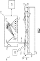
- Figure 2 schematically shows an example structure 100 with a surface 102.
- the structure 100 can be any structure in the engine 20.
- the surface 102 can be a surface in a gas turbine engine 20 that is operational or a gas turbine engine 20 or section of a gas turbine engine 20 used for testing.
- the surface 20 can be a surface in another type of vehicle or machine, as discussed above.
- a pressure sensing device 104 is arranged on the surface 102.
- the pressure sensing device 104 can cover parts of the surface 102 or the entire surface 102.
- the pressure sensing device 104 includes a pressure sensing film 105.
- the pressure sensing film 105 generally includes a flexible transparent film 106 sandwiched between two outer films 108, 110.
- the outer films 108, 110 generally serve to form an optical cavity 120 (discussed in more detail below) therebetween. For instance, the outer films 108, 110 may trap at least some light waves therebetween.
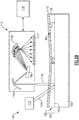
- the first film 108 is replaced by the surface 102. That is, the flexible transparent film 106 is arranged directly adjacent the surface 102.
- the surface 102 may be polished.
- the surface 102 acts like the first film 108 in any of the examples discussed below.
- a first film 108 is a metallic film and is reflective, meaning that the first metallic film 108 reflects substantially all of the light that encounters it.
- the first film 108 may be a thin film, e.g., have a thickness between about 1 nm and 5000 nm. In general, thin films are at least somewhat reflective. In another example, the first film 108 may be polished metal.
- a second outer film 110 is arranged on an opposite side of the flexible transparent film 106 from the first metallic film 108.
- the second outer film 110 is a semi-transparent metallic film, meaning that it reflects only some of the light that encounters it, and remaining light passes through the second metallic film 110.
- the pressure sensing device 104 includes a light source 112 that is configured to shine light onto the pressure sensing film 105.
- a beam of light is schematically represented as 114a, though it should be understood the light from the light source 112 contains many such beams.
- the light source 112 can be any type of light source, such as a light source that provides a combination of light of different wavelengths ("white light").
- the light source 112 can provide a particular type of light, such as ultraviolet, visible, short-wave-infrared, mid-infrared, far-infrared, for instance.
- the light resonates within an optical cavity 120 in the pressure sensing film 105, discussed below, and is reflected out of the optical cavity by the first metallic film 108.
- a reflected light beam is schematically illustrated as 114b, though it should be understood the reflected light contains many such beams.
- the reflected light is indicative of the characteristics of the resonance of the light within the optical cavity.
- a device capable of recording/analyzing light spectra such as a spectrograph 115, is configured to capture "photographs" of the reflected light from the optical cavity 120. Accordingly, the information captured by the spectrograph 115 are indicative of the characteristics of the resonance of the light within the optical cavity.
- the reflected light can be captured from a point within the pressure sensing device 104 or across an area of the pressure sensing device 104, or both. For the latter, local pressures at individual points can also captured, so that a pressure "map" of pressures experienced by the component 102 is created.
- the spectrograph 115 is operable to send information about the reflected light to a computing device 118 that includes processors or other hardware programmed to analyze the information.
- the computing device 118 can be local to or remote from the spectrograph 115.
- the computing device 118 is operable to analyze the information from the spectrograph 115 in order to determine pressure experienced by the pressure sensing film 105, as will be discussed in more detail below.
- the computing device 118 is also programmed to filter the information from the spectrograph 116 to reduce noise in the signals from the spectrograph 116 according to any known filtering techniques.
- the spectrograph 115 can be any known type of spectrograph.
- the spectrograph 115 includes a focusing mirror 116a to focus the light beam 114b and a flat mirror 116b to direct the light beam 114b towards a diffraction grating 116c.
- the diffraction grating 116c disperses the light beam 114b into a frequency spectrum which is captured by a detector 117.
- the outer films 108, 110 have thicknesses M1 and M2, respectively.
- the transparency of the first and second metallic films 108, 110 is related to the thickness and the composition of the first and second metallic films 108, 110.
- the thickness M1 of the first metallic film 108 is selected based on the composition of the first metallic film 108 so that substantially all of the light beam 114a is reflected by the first metallic film 108.
- the thickness M2 of the second metallic film 110 is selected based on the composition of the second metallic film 110 so that at least some of the light beams 114a, 114b travel through the second metallic film 110.
- the metallic films 108, 110 comprise gold.
- a first gold metallic film 108 is between about 50 and 250 nanometers thick and a second gold metallic film 110 is between about 10 and 50 nanometers thick.
- the metallic films 108, 110 can be deposited according to any known method, such as sputter coating or atomic layer deposition.
- Other example metallic films comprise nickel, titanium, aluminum, platinum, gold, other metals, or combinations thereof.
- the "metallic films” comprise other types of materials that have metal-like properties, such as titanium nitride and zirconium nitride or other transition metal nitrides.
- An optical cavity 120 is thus formed in the flexible transparent film 106 between the two metallic films 108, 110.
- the optical cavity 120 traps light in between the outer films 108, 110 so that the light resonates in the optical cavity 120.
- the optical cavity 120 has multiple resonance bands over a broad electromagnetic spectrum from ultraviolet to microwave. Resonance within the optical cavity 120 is related to an optical path length within the optical cavity 120, e.g., the geometry of the pathway of light beams 114a, 114b through the optical cavity 120. Accordingly, the thickness of the flexible transparent film 106 and thus the thickness of the optical cavity 120 is related to the resonance within the optical cavity 120.
- At least one of the outer films 108, 110 comprise stacked dielectric layers ("dielectric mirrors"), which are operable to reflect some wavelengths of light.
- dielectric mirrors stacked dielectric layers
- Other reflective or semi-transparent materials are also contemplated.
- the stacked layers can comprise alternating layers of dielectric and metallic materials forming a composite layer capable of selectively reflecting and transmitting light.
- both the first and second outer films 108, 110 are semi-transparent.
- the pressure sensing device 104 is symmetrical, and the spectrograph 115 measures light transmitted through the optical cavity 120. Accordingly, the spectrograph 115 and light source 112 can be arranged on opposite sides of the pressure sensing device 105, in this example.
- the flexible transparent film 106 is a polymeric material.
- the flexible transparent film 106 is a polymeric material with a Young's modulus (which is related to stiffness of the transparent film 106) that is related to a degree of cross-linking within the polymeric material. That is, the Young's modulus, and thus the stiffness, of the polymeric material can be controlled by controlling the degree of cross-linking in the polymeric material by any known chemistry.
- PDMS polydimethylsiloxane
- the degree of cross-linking is related to the ratio of PDMS base material to curing agent during the PDMS synthesizing process and its Young' modulus can vary between about 3 kPa (low cross-linking) to about 3000 kPa (high cross-linking).
- Another example polymeric material is a high temperature polyamide.
- the flexible transparent film 106 can be deposited onto the reflective metallic film 108 by any known method, such as spin coating or dip coating.
- the flexible transparent film 106 can include luminescent particles, such as nanocrystals or dyes, which produce an optical signal that can be read by the spectrograph 115.
- the particles can be added to the polymer pre-cursor for the flexible transparent film 106 before cross-linking the precursor to form the flexible transparent form 106, in one example.
- the particles can provide additional functionality to the flexible transparent film 106. For instance, particles that are thermographic phosphors can allow for temperature sensing in the flexible transparent film 106, which can allow for calibration of pressure measurements due to local temperature changes.
- the flexible transparent film 106 has a resting thickness T1.
- the resting thickness T1 is the thickness of the flexible transparent film 106 in an environment where the air pressure is ambient air pressure. In one example, the resting thickness T1 is on the order of nanometers to centimeters.
- the flexible transparent film 106 is locally compressed (e.g., experiences strain) when its local environment (e.g., the environment outside of the pressure sensing film 105) is under pressures higher than ambient air pressure. Accordingly, the flexible transparent film 106 has a compressed thickness T2 in areas where pressure is higher than ambient air pressure.
- ⁇ the pressure
- E the Young's modulus of the flexible transparent film 106.
- the resting thickness, T1 is 1000 nm and the nominal wavelength is 1000 nm for the light beams 114a, 114b.
- Young's modulus of E 3 kPa (3000 Pa)
- ⁇ ⁇ ) of 10 Pa results in a ⁇ T of about 3 nanometers, which results in a comparable resonance shift in wavelength.
- the thickness of the flexible transparent film 106 and thus the optical cavity 120 is related to the resonance of light beams 114a, 114b within the optical cavity.
- the spectrograph 115 is a hyperspectral camera that can resolve resonance changes associated with changes in thickness ( ⁇ T) of the optical cavity 120 of about 2 nanometers.
- a hyperspectral camera is known in the art and generally includes individual pixels each working as spectrographs in order to "image" spectral distributions over a surface like the surface 102.
- the pressure sensing device 104 is capable of resolving changes in pressure of 10 Pa across a surface 102. This resolution is orders of magnitude higher than prior art devices. For instance, the resolution of pressure sensitive paint is on the order of about 1000 Pa.
- Equation 2 above holds when resonance frequencies inside the optical cavity 120 are below a cutoff frequency Fc.
- the cutoff frequency Fc is related to the mechanical responsiveness of the flexible transparent film 106 in response to fast pressure changes, which in turn is related to response time of the pressure sensing device 104, e.g., how quickly the pressure sensing device 104 can respond in order to measure fast pressure changes at a given area of the surface 102.
- the cutoff frequency Fc is associated with the wavelength of an elastic wave in the flexible transparent film 106 approaching the thickness of the flexible transparent film 106.
- the cutoff frequency Fc can be determined when the wavelength is two times the thickness of the flexible film 106.
- the cutoff frequency Fc is estimated to be about 870 kHz. This is significantly higher than the cutoff frequency for prior art devices.
- the cutoff frequency for pressure sensitive paint ranges from 10 to 100 kHz.
- the pressure sensing device 104 thus provides high-resolution and fast pressure measurements for pressures experienced by surface 102.
- the pressure sensing film 105 is a continuous film over the surface 102. However, in other examples, the pressure sensing film 105 can be non-continuous.
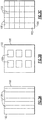
- Figures 3A-C show example arrangements of pressure sensing film 105 on the surface 102.
- the pressure sensing film 105 is arranged in a series of mechanically independent or decoupled sections on the surface 102.
- Figure 3B the pressure sensing film 105 is arranged in independent sections on the surface 102. The independent sections can have any shape or arrangement.
- the pressure sensing film 105 is arranged within a frame 122.
- the frame 122 partitions the surface 102 and is rigid, e.g., it is much less compressible than the flexible transparent film 106.
- the frame 122 thus decouples individual sections of the pressure sensing film 105 so that each individual section produces a pressure reading independent of the others. Though certain example arrangements are shown in Figures 3A-C , these arrangements are only exemplary, and other arrangements are contemplated.
- the pressure sensing film 105 can comprise multiple flexible transparent films and/or optical cavities.
- a second flexible transparent film 206 is sandwiched between outer layer 110 and outer layer 111. Though two flexible transparent films 106, 206 are shown, more flexible transparent films and outer layers are contemplated.
- each flexible transparent film 106, 206 can be configured to address different pressure ranges and associated spectral bands.
- the first flexible transparent film 106 can be configured to sense a broad pressure range and the second transparent film 206 can be configured for a finer pressure range for accurate measurements in that pressure range.
Landscapes
- Physics & Mathematics (AREA)
- General Physics & Mathematics (AREA)
- Measuring Fluid Pressure (AREA)
Abstract
Description
- During the design and operation of gas turbine engines and other vehicles or machines, various elements experience various air pressures. For example, a gas turbine engine typically includes a fan section, a compressor section, a combustor section and a turbine section. Air entering the compressor section is compressed and delivered into the combustion section where it is mixed with fuel and ignited to generate a high-energy exhaust gas flow. The high-energy exhaust gas flow expands through the turbine section to drive the compressor and the fan section. The compressor section typically includes low and high pressure compressors, and the turbine section includes low and high pressure turbines.
- The high pressure turbine drives the high pressure compressor through an outer shaft to form a high spool, and the low pressure turbine drives the low pressure compressor through an inner shaft to form a low spool. The fan section may also be driven by the low inner shaft. A direct drive gas turbine engine includes a fan section driven by the low spool such that the low pressure compressor, low pressure turbine and fan section rotate at a common speed in a common direction.
- A speed reduction device such as an epicyclical gear assembly may be utilized to drive the fan section such that the fan section may rotate at a speed different than the turbine section so as to increase the overall propulsive efficiency of the engine. In such engine architectures, a shaft driven by one of the turbine sections provides an input to the epicyclical gear assembly that drives the fan section at a reduced speed such that both the turbine section and the fan section can rotate at closer to optimal speeds.
- Although geared architectures have improved propulsive efficiency, turbine engine manufacturers continue to seek further improvements to engine performance including improvements to thermal, transfer and propulsive efficiencies.
- These components experience air pressures as the air travels through the engine.
- According to a first aspect of the present invention there is provided a pressure sensing film comprising first and second films. The first and second films are configured to form an optical cavity therebetween. A flexible transparent film is arranged in the optical cavity. The flexible transparent film is compressible in response to a pressure change in air adjacent the pressure sensing film.
- In an embodiment of the above embodiment, at least one of the first and second films is metallic.
- In an embodiment of any of the above embodiments, at least one of the first and second films are comprised of gold.
- In an embodiment of any of the above embodiments, at least one of the first and second film are comprised of stacked dielectric layers.
- In an embodiment of any of the above embodiments, the first film is reflective and the second film is semi-transparent.
- In an embodiment of any of the above embodiments, the first and second films are semi-transparent.
- In an embodiment of any of the above embodiments, the flexible transparent film comprises a polymeric material.
- In an embodiment of any of the above embodiments, the flexible transparent film comprises luminescent particles.
- In an embodiment of any of the above embodiments, the luminescent particles are thermographic phosphors.
- In an embodiment of any of the above embodiments, the pressure sensing film is configured to sense a pressure adjacent a surface of a structure in a gas turbine engine.
- According to a second aspect of the present invention there is provided a pressure sensing device comprising a pressure sensing film. The pressure sensing film includes first and second films. The first and second films are configured to form an optical cavity therebetween. A flexible transparent film is arranged in the optical cavity. The flexible transparent film is compressible in response to a pressure change in air adjacent the pressure sensing film. A light source is configured to shine light onto the pressure sensing film. A spectrograph is configured to photograph light from the pressure sensing film, and a computing device is configured to analyze information from the spectrograph to determine a pressure change in the air adjacent the pressure sensing film based on compression of the flexible transparent film.
- In an embodiment of the above embodiment, at least one of the first and second films are metallic.
- In an embodiment of any of the above embodiments, at least one of the first and second film are comprised of stacked dielectric layers.
- In an embodiment of any of the above embodiments, the first film is reflective and the second film is semi-transparent.
- In an embodiment of any of the above embodiments, the spectrograph is configured to capture a photograph of light reflected from the first film.
- In an embodiment of any of the above embodiments, the first and second films are semi-transparent.
- In an embodiment of any of the above embodiments, the spectrograph is configured to capture a photograph of light transmitted through from the first and second films.
- According to a third aspect of the present invention, there is provided a method of sensing pressure adjacent a surface comprising shining a light source on a pressure sensing film. The pressure sensing film includes first and second films. The first and second films are configured to form an optical cavity therebetween. A flexible transparent film is arranged in the optical cavity. The flexible transparent film is compressible in response to a pressure change in air adjacent the pressure sensing film, collecting information about light from the pressure sensing film and analyzing the information to determine a pressure change in the air adjacent the pressure sensing film based on compression of the flexible transparent film.
- In an embodiment of the above embodiments, the information is filtered to reduce noise.
- In an embodiment of any of the above embodiments, the collecting is accomplished at least in part by a spectrograph.
- Although the different examples have the specific components shown in the illustrations, embodiments of this invention are not limited to those particular combinations. It is possible to use some of the components or features from one of the examples in combination with features or components from another one of the examples.
- These and other features disclosed herein can be best understood from the following specification and drawings, the following of which is a brief description.
-
-
Figure 1 is a schematic view of an example gas turbine engine. -
Figure 2 schematically shows an embodiment of a pressure sensing device according to the present invention. -
Figure 2B schematically shows a second embodiment of a pressure sensing device according to the present invention. -
Figures 3A-C schematically show example embodiments of a pressure sensing film of an embodiment of a pressure sensing device according to the present invention on a surface. -
Figure 4 schematically shows an embodiment of an alternate pressure sensing film according to the present invention. - The present application relates to a pressure-sensing device for sensing the pressure on a surface. The surface can be any surface. For instance, the concepts described herein can be applied to gas turbine engines, as shown in
Figure 1 and discussed below. However, it should be understood that the instant disclosure is not limited to gas turbine engines. The concepts described herein can also be applied to other types of vehicles, such as trains (e.g., maglev trains), automobiles, or other types of machinery or applications where pressure sensing is desired. -
Figure 1 schematically illustrates agas turbine engine 20. Thegas turbine engine 20 is disclosed herein as a two-spool turbofan that generally incorporates afan section 22, acompressor section 24, acombustor section 26 and aturbine section 28. Thefan section 22 drives air along a bypass flow path B in a bypass duct defined within ahousing 15 such as a fan case or nacelle, and also drives air along a core flow path C for compression and communication into thecombustor section 26 then expansion through theturbine section 28. Although depicted as a two-spool turbofan gas turbine engine in the disclosed non-limiting embodiment, it should be understood that the concepts described herein are not limited to use with two-spool turbofans as the teachings may be applied to other types of turbine engines including but not limited to three-spool architectures. - The
exemplary engine 20 generally includes alow speed spool 30 and ahigh speed spool 32 mounted for rotation about an engine central longitudinal axis A relative to an enginestatic structure 36 viaseveral bearing systems 38. It should be understood that various bearingsystems 38 at various locations may alternatively or additionally be provided, and the location of bearingsystems 38 may be varied as appropriate to the application. - The
low speed spool 30 generally includes aninner shaft 40 that interconnects, a first (or low)pressure compressor 44 and a first (or low)pressure turbine 46. Theinner shaft 40 is connected to thefan 42 through a speed change mechanism, which in exemplarygas turbine engine 20 is illustrated as a gearedarchitecture 48 to drive afan 42 at a lower speed than thelow speed spool 30. Thehigh speed spool 32 includes anouter shaft 50 that interconnects a second (or high)pressure compressor 52 and a second (or high)pressure turbine 54. Acombustor 56 is arranged inexemplary gas turbine 20 between thehigh pressure compressor 52 and thehigh pressure turbine 54. Amid-turbine frame 57 of the enginestatic structure 36 may be arranged generally between thehigh pressure turbine 54 and thelow pressure turbine 46. Themid-turbine frame 57 furthersupports bearing systems 38 in theturbine section 28. Theinner shaft 40 and theouter shaft 50 are concentric and rotate via bearingsystems 38 about the engine central longitudinal axis A which is collinear with their longitudinal axes. - The core airflow is compressed by the
low pressure compressor 44 then thehigh pressure compressor 52, mixed and burned with fuel in thecombustor 56, then expanded over thehigh pressure turbine 54 andlow pressure turbine 46. Themid-turbine frame 57 includesairfoils 59 which are in the core airflow path C. Theturbines low speed spool 30 andhigh speed spool 32 in response to the expansion. It will be appreciated that each of the positions of thefan section 22,compressor section 24,combustor section 26,turbine section 28, and fandrive gear system 48 may be varied. For example,gear system 48 may be located aft of the low pressure compressor, or aft of thecombustor section 26 or even aft ofturbine section 28, andfan 42 may be positioned forward or aft of the location ofgear system 48. - The
engine 20 in one example is a high-bypass geared aircraft engine. In a further example, theengine 20 bypass ratio is greater than about 6:1, with an example embodiment being greater than about 10:1, the gearedarchitecture 48 is an epicyclic gear train, such as a planetary gear system or other gear system, with a gear reduction ratio of greater than about 2.3:1 and thelow pressure turbine 46 has a pressure ratio that is greater than about 5:1. In one disclosed embodiment, theengine 20 bypass ratio is greater than about 10:1, the fan diameter is significantly larger than that of thelow pressure compressor 44, and thelow pressure turbine 46 has a pressure ratio that is greater than about 5:1.Low pressure turbine 46 pressure ratio is pressure measured prior to inlet oflow pressure turbine 46 as related to the pressure at the outlet of thelow pressure turbine 46 prior to an exhaust nozzle. The gearedarchitecture 48 may be an epicycle gear train, such as a planetary gear system or other gear system, with a gear reduction ratio of greater than about 2.3:1 and less than about 5:1. It should be understood, however, that the above parameters are only exemplary of one embodiment of a geared architecture engine and that the present invention is applicable to other gas turbine engines but not limited to including direct drive turbofans, as well as other types of vehicles and machinery. - A significant amount of thrust is provided by the bypass flow B due to the high bypass ratio. The
fan section 22 of theengine 20 is designed for a particular flight condition -- typically cruise at about 0.8 Mach and about 35,000 feet (10,668 meters). The flight condition of 0.8 Mach and 35,000 ft (10,668 meters), with the engine at its best fuel consumption - also known as "bucket cruise Thrust Specific Fuel Consumption ('TSFC')" - is the industry standard parameter of lbm of fuel being burned divided by lbf of thrust the engine produces at that minimum point. "Low fan pressure ratio" is the pressure ratio across the fan blade alone, without a Fan Exit Guide Vane ("FEGV") system. The low fan pressure ratio as disclosed herein according to one non-limiting embodiment is less than about 1.45. "Low corrected fan tip speed" is the actual fan tip speed in ft/sec divided by an industry standard temperature correction of [(Tram °R) / (518.7 °R)]0.5 (where °R = K x 9/5). The "Low corrected fan tip speed" as disclosed herein according to one non-limiting embodiment is less than about 1150 ft / second (350.5 meters/second). - Structures of the
gas turbine engine 20 experience various air pressures during operation of theengine 20. For instance, thefan 42,compressors turbines housing 15 experiences varying air pressures. It should be understood that other structures within theengine 20, even those not specifically described above, would be known by one of ordinary skill in the art to experience various pressures and can incorporate the features described herein. In some cases, the air pressures experienced by the structures of theengine 20 are variable and depend on the operating conditions or mode of theengine 20. - Turning now to
Figure 2, Figure 2 schematically shows anexample structure 100 with asurface 102. As discussed above, thestructure 100 can be any structure in theengine 20. Thesurface 102 can be a surface in agas turbine engine 20 that is operational or agas turbine engine 20 or section of agas turbine engine 20 used for testing. In another example, thesurface 20 can be a surface in another type of vehicle or machine, as discussed above. - A
pressure sensing device 104 is arranged on thesurface 102. Thepressure sensing device 104 can cover parts of thesurface 102 or theentire surface 102. Thepressure sensing device 104 includes apressure sensing film 105. Thepressure sensing film 105 generally includes a flexibletransparent film 106 sandwiched between twoouter films outer films outer films - In another example, shown in
Figure 2B , thefirst film 108 is replaced by thesurface 102. That is, the flexibletransparent film 106 is arranged directly adjacent thesurface 102. Thesurface 102 may be polished. In this example, thesurface 102 acts like thefirst film 108 in any of the examples discussed below. - In the example of
Figure 2 , afirst film 108 is a metallic film and is reflective, meaning that the firstmetallic film 108 reflects substantially all of the light that encounters it. Thefirst film 108 may be a thin film, e.g., have a thickness between about 1 nm and 5000 nm. In general, thin films are at least somewhat reflective. In another example, thefirst film 108 may be polished metal. - A second
outer film 110 is arranged on an opposite side of the flexibletransparent film 106 from the firstmetallic film 108. In one example, the secondouter film 110 is a semi-transparent metallic film, meaning that it reflects only some of the light that encounters it, and remaining light passes through the secondmetallic film 110. Thepressure sensing device 104 includes alight source 112 that is configured to shine light onto thepressure sensing film 105. A beam of light is schematically represented as 114a, though it should be understood the light from thelight source 112 contains many such beams. Thelight source 112 can be any type of light source, such as a light source that provides a combination of light of different wavelengths ("white light"). In other examples, thelight source 112 can provide a particular type of light, such as ultraviolet, visible, short-wave-infrared, mid-infrared, far-infrared, for instance. The light resonates within anoptical cavity 120 in thepressure sensing film 105, discussed below, and is reflected out of the optical cavity by the firstmetallic film 108. A reflected light beam is schematically illustrated as 114b, though it should be understood the reflected light contains many such beams. The reflected light is indicative of the characteristics of the resonance of the light within the optical cavity. - A device capable of recording/analyzing light spectra, such as a
spectrograph 115, is configured to capture "photographs" of the reflected light from theoptical cavity 120. Accordingly, the information captured by thespectrograph 115 are indicative of the characteristics of the resonance of the light within the optical cavity. The reflected light can be captured from a point within thepressure sensing device 104 or across an area of thepressure sensing device 104, or both. For the latter, local pressures at individual points can also captured, so that a pressure "map" of pressures experienced by thecomponent 102 is created. Thespectrograph 115 is operable to send information about the reflected light to acomputing device 118 that includes processors or other hardware programmed to analyze the information. Thecomputing device 118 can be local to or remote from thespectrograph 115. Thecomputing device 118 is operable to analyze the information from thespectrograph 115 in order to determine pressure experienced by thepressure sensing film 105, as will be discussed in more detail below. In some examples, thecomputing device 118 is also programmed to filter the information from the spectrograph 116 to reduce noise in the signals from the spectrograph 116 according to any known filtering techniques. - The
spectrograph 115 can be any known type of spectrograph. In one example, thespectrograph 115 includes a focusingmirror 116a to focus thelight beam 114b and aflat mirror 116b to direct thelight beam 114b towards adiffraction grating 116c. Thediffraction grating 116c disperses thelight beam 114b into a frequency spectrum which is captured by a detector 117. - The
outer films metallic films metallic films metallic film 108 is selected based on the composition of the firstmetallic film 108 so that substantially all of thelight beam 114a is reflected by the firstmetallic film 108. The thickness M2 of the secondmetallic film 110 is selected based on the composition of the secondmetallic film 110 so that at least some of thelight beams metallic film 110. In a particular example, themetallic films metallic film 108 is between about 50 and 250 nanometers thick and a second goldmetallic film 110 is between about 10 and 50 nanometers thick. Themetallic films optical cavity 120 is thus formed in the flexibletransparent film 106 between the twometallic films optical cavity 120 traps light in between theouter films optical cavity 120. Theoptical cavity 120 has multiple resonance bands over a broad electromagnetic spectrum from ultraviolet to microwave. Resonance within theoptical cavity 120 is related to an optical path length within theoptical cavity 120, e.g., the geometry of the pathway oflight beams optical cavity 120. Accordingly, the thickness of the flexibletransparent film 106 and thus the thickness of theoptical cavity 120 is related to the resonance within theoptical cavity 120. - In another example, at least one of the
outer films - In yet another example, both the first and second
outer films pressure sensing device 104 is symmetrical, and thespectrograph 115 measures light transmitted through theoptical cavity 120. Accordingly, thespectrograph 115 andlight source 112 can be arranged on opposite sides of thepressure sensing device 105, in this example. - In one example, the flexible
transparent film 106 is a polymeric material. In a more particular example, the flexibletransparent film 106 is a polymeric material with a Young's modulus (which is related to stiffness of the transparent film 106) that is related to a degree of cross-linking within the polymeric material. That is, the Young's modulus, and thus the stiffness, of the polymeric material can be controlled by controlling the degree of cross-linking in the polymeric material by any known chemistry. One example such polymeric material is PDMS (polydimethylsiloxane). For PDMS, the degree of cross-linking is related to the ratio of PDMS base material to curing agent during the PDMS synthesizing process and its Young' modulus can vary between about 3 kPa (low cross-linking) to about 3000 kPa (high cross-linking). Another example polymeric material is a high temperature polyamide. The flexibletransparent film 106 can be deposited onto the reflectivemetallic film 108 by any known method, such as spin coating or dip coating. - In one example, the flexible
transparent film 106 can include luminescent particles, such as nanocrystals or dyes, which produce an optical signal that can be read by thespectrograph 115. The particles can be added to the polymer pre-cursor for the flexibletransparent film 106 before cross-linking the precursor to form the flexibletransparent form 106, in one example. The particles can provide additional functionality to the flexibletransparent film 106. For instance, particles that are thermographic phosphors can allow for temperature sensing in the flexibletransparent film 106, which can allow for calibration of pressure measurements due to local temperature changes. - The flexible
transparent film 106 has a resting thickness T1. The resting thickness T1 is the thickness of the flexibletransparent film 106 in an environment where the air pressure is ambient air pressure. In one example, the resting thickness T1 is on the order of nanometers to centimeters. The flexibletransparent film 106 is locally compressed (e.g., experiences strain) when its local environment (e.g., the environment outside of the pressure sensing film 105) is under pressures higher than ambient air pressure. Accordingly, the flexibletransparent film 106 has a compressed thickness T2 in areas where pressure is higher than ambient air pressure. The amount of compression is directly related to the pressure according to the following Equation 1:
transparent film 106. The local change in surface pressure (Δσ) relative to ambient pressure results in the change in thickness (ΔT = T1-T2) according to the following Equation 2:
- In a particular example, the resting thickness, T1, is 1000 nm and the nominal wavelength is 1000 nm for the
light beams transparent film 106 and thus theoptical cavity 120 is related to the resonance oflight beams - In some examples, the
spectrograph 115 is a hyperspectral camera that can resolve resonance changes associated with changes in thickness (ΔT) of theoptical cavity 120 of about 2 nanometers. A hyperspectral camera is known in the art and generally includes individual pixels each working as spectrographs in order to "image" spectral distributions over a surface like thesurface 102. Accordingly, thepressure sensing device 104 is capable of resolving changes in pressure of 10 Pa across asurface 102. This resolution is orders of magnitude higher than prior art devices. For instance, the resolution of pressure sensitive paint is on the order of about 1000 Pa. - Equation 2 above holds when resonance frequencies inside the
optical cavity 120 are below a cutoff frequency Fc. The cutoff frequency Fc is related to the mechanical responsiveness of the flexibletransparent film 106 in response to fast pressure changes, which in turn is related to response time of thepressure sensing device 104, e.g., how quickly thepressure sensing device 104 can respond in order to measure fast pressure changes at a given area of thesurface 102. The cutoff frequency Fc is associated with the wavelength of an elastic wave in the flexibletransparent film 106 approaching the thickness of the flexibletransparent film 106. The frequency f of the elastic wave in the flexibletransparent film 106 is approximately related to its wavelength λe according to Equation 3 below:
transparent film 106 in theoptical cavity 120. For instance, the cutoff frequency Fc can be determined when the wavelength is two times the thickness of theflexible film 106. In a more particular example, the flexibletransparent film 106 is highly-diluted PDMS (e.g., PDMS with a low level of cross-linking) with E = 3000 Pa, ρ = 1000 kg/m3, and a thickness of 1000 nanometers. In this example, the cutoff frequency Fc is estimated to be about 870 kHz. This is significantly higher than the cutoff frequency for prior art devices. For instance, the cutoff frequency for pressure sensitive paint ranges from 10 to 100 kHz. - The
pressure sensing device 104 thus provides high-resolution and fast pressure measurements for pressures experienced bysurface 102. - In the example of
Figures 2 and2B , thepressure sensing film 105 is a continuous film over thesurface 102. However, in other examples, thepressure sensing film 105 can be non-continuous.Figures 3A-C show example arrangements ofpressure sensing film 105 on thesurface 102. InFigure 3A , thepressure sensing film 105 is arranged in a series of mechanically independent or decoupled sections on thesurface 102. InFigure 3B , thepressure sensing film 105 is arranged in independent sections on thesurface 102. The independent sections can have any shape or arrangement. InFigure 3C , thepressure sensing film 105 is arranged within aframe 122. Theframe 122 partitions thesurface 102 and is rigid, e.g., it is much less compressible than the flexibletransparent film 106. Theframe 122 thus decouples individual sections of thepressure sensing film 105 so that each individual section produces a pressure reading independent of the others. Though certain example arrangements are shown inFigures 3A-C , these arrangements are only exemplary, and other arrangements are contemplated. - In another example, the
pressure sensing film 105 can comprise multiple flexible transparent films and/or optical cavities. In this example illustrated inFigure 4 , a second flexibletransparent film 206 is sandwiched betweenouter layer 110 andouter layer 111. Though two flexibletransparent films transparent film transparent film 106 can be configured to sense a broad pressure range and the secondtransparent film 206 can be configured for a finer pressure range for accurate measurements in that pressure range. - Although the different examples are illustrated as having specific components, the examples of this disclosure are not limited to those particular combinations. It is possible to use some of the components or features from any of the embodiments in combination with features or components from any of the other embodiments.
- The foregoing description shall be interpreted as illustrative and not in any limiting sense. A worker of ordinary skill in the art would understand that certain modifications could come within the scope of this disclosure. For these reasons, the following claims should be studied to determine the true scope and content of this disclosure.
Claims (15)
- A pressure sensing film (105), comprising:first and second films (108, 110), the first and second films (108, 110) configured to form an optical cavity (120) therebetween; anda flexible transparent film (106) arranged in the optical cavity (120), wherein the flexible transparent film (106) is compressible in response to a pressure change in air adjacent the pressure sensing film (105).
- The pressure sensing film of claim 1, wherein at least one of the first and second films (108, 110) is metallic.
- The pressure sensing film of claim 2, wherein at least one of the first and second films (108, 110) comprises gold.
- The pressure sensing film of any of claims 1 to 3, wherein at least one of the first and second films (108, 110) comprises stacked dielectric layers.
- The pressure sensing film of any of claims 1 to 4, wherein the first film (108) is reflective and the second film (110) is semi-transparent.
- The pressure sensing film of any of claims 1 to 4, wherein both the first and second films (108, 110) are semi-transparent.
- The pressure sensing film of any of claims 1 to 6, wherein the flexible transparent film (106) comprises a polymeric material.
- The pressure sensing film of claim 7, wherein the flexible transparent film (106) comprises luminescent particles.
- The pressure sensing film of claim 8, wherein the luminescent particles are thermographic phosphors.
- The pressure sensing film of any of claims 1 to 9, wherein the pressure sensing film (106) is configured to sense a pressure adjacent a surface of a structure (100) in a gas turbine engine (20).
- A pressure sensing device (104), comprising:
a pressure sensing film (105) according to any of claims 1 to 10;:a light source (112) configured to shine light (114a) onto the pressure sensing film (105);a device (115) configured to analyze light (114b) from the pressure sensing film (105); anda computing device (118) configured to analyze information from the device (115) to determine a pressure change in the air adjacent the pressure sensing film (105) based on compression of the flexible transparent film (106). - The pressure sensing device of claim 11, wherein the device (115) is configured to capture a photograph of light reflected from the first film (108) when the first film (108) is reflective and the second film (110) is semi-transparent.
- The pressure sensing device of claim 11, wherein the device (115) is configured to capture a photograph of light transmitted through from the first and second films (108, 110) when the first and second films (108, 110) are semi-transparent.
- A method of sensing pressure adjacent a surface (102), comprising:
shining a light source (112) on a pressure sensing film (105), the pressure sensing film (105) comprising:first and second films (108, 110), the first and second films (108, 110) configured to form an optical cavity (120) therebetween; anda flexible transparent film (106) arranged in the optical cavity (120), wherein the flexible transparent film (106) is compressible in response to a pressure change in air adjacent the pressure sensing film (105);collecting information about light (114b) from the pressure sensing film (105); andanalyzing the information to determine a pressure change in the air adjacent the pressure sensing film (105) based on compression of the flexible transparent film (106), and, optionally, the collecting is accomplished at least in part by a spectrograph (115). - The method of claim 14 further comprising filtering the information to reduce noise.
Applications Claiming Priority (1)
| Application Number | Priority Date | Filing Date | Title |
|---|---|---|---|
| US16/522,917 US11131595B2 (en) | 2019-07-26 | 2019-07-26 | Pressure sensing device and method for using the same |
Publications (2)
| Publication Number | Publication Date |
|---|---|
| EP3770572A2 true EP3770572A2 (en) | 2021-01-27 |
| EP3770572A3 EP3770572A3 (en) | 2021-04-21 |
Family
ID=71741705
Family Applications (1)
| Application Number | Title | Priority Date | Filing Date |
|---|---|---|---|
| EP20187214.0A Ceased EP3770572A3 (en) | 2019-07-26 | 2020-07-22 | Pressure sensing device and method for using the same |
Country Status (2)
| Country | Link |
|---|---|
| US (1) | US11131595B2 (en) |
| EP (1) | EP3770572A3 (en) |
Citations (1)
| Publication number | Priority date | Publication date | Assignee | Title |
|---|---|---|---|---|
| US5889590A (en) * | 1997-03-28 | 1999-03-30 | General Electric Company | Optical cavity sensor |
Family Cites Families (16)
| Publication number | Priority date | Publication date | Assignee | Title |
|---|---|---|---|---|
| US4859060A (en) * | 1985-11-26 | 1989-08-22 | 501 Sharp Kabushiki Kaisha | Variable interferometric device and a process for the production of the same |
| US4933545A (en) * | 1985-12-30 | 1990-06-12 | Metricor, Inc. | Optical pressure-sensing system using optical resonator cavity |
| JP2003214958A (en) * | 2002-01-21 | 2003-07-30 | Gigaphoton Inc | Wavelength detecting device, laser device, and wavelength detecting method |
| AUPS098002A0 (en) * | 2002-03-08 | 2002-03-28 | University Of Western Australia, The | Tunable cavity resonator, and method of fabricating same |
| EP2495212A3 (en) * | 2005-07-22 | 2012-10-31 | QUALCOMM MEMS Technologies, Inc. | Mems devices having support structures and methods of fabricating the same |
| KR20160125531A (en) * | 2008-01-30 | 2016-10-31 | 다우 글로벌 테크놀로지스 엘엘씨 | PROPYLENE/α-OLEFIN BLOCK INTERPOLYMERS |
| EP2529201A1 (en) * | 2010-01-27 | 2012-12-05 | Luxcel Biosciences Ltd. | Photoluminescent pressure probe |
| US8348504B2 (en) * | 2010-05-12 | 2013-01-08 | Wireless Sensor Technologies, Llc | Wireless temperature measurement system and methods of making and using same |
| US8710611B2 (en) | 2011-01-20 | 2014-04-29 | West Virginia University | High sensitivity stress sensor based on hybrid materials |
| US20130127879A1 (en) | 2011-11-18 | 2013-05-23 | Qualcomm Mems Technologies, Inc. | Glass-encapsulated pressure sensor |
| US8695430B1 (en) * | 2011-11-23 | 2014-04-15 | The United States Of America As Represented By The Administrator Of National Aeronautics And Space Administration | Temperature and pressure sensors based on spin-allowed broadband luminescence of doped orthorhombic perovskite structures |
| US9200973B2 (en) * | 2012-06-28 | 2015-12-01 | Intel Corporation | Semiconductor package with air pressure sensor |
| DK3004829T3 (en) * | 2013-06-06 | 2018-04-30 | Univ Denmark Tech Dtu | Optical pressure sensor |
| CN114686137B (en) * | 2015-12-04 | 2025-04-15 | 雷恩哈德库兹基金两合公司 | Membrane and method for producing the same |
| US10139975B2 (en) * | 2016-09-23 | 2018-11-27 | Apple Inc. | Pressure compensation for force-sensitive touch screen |
| US11261800B2 (en) * | 2018-10-24 | 2022-03-01 | Raytheon Technologies Corporation | Adaptive bleed schedule in a gas turbine engine |
-
2019
- 2019-07-26 US US16/522,917 patent/US11131595B2/en active Active
-
2020
- 2020-07-22 EP EP20187214.0A patent/EP3770572A3/en not_active Ceased
Patent Citations (1)
| Publication number | Priority date | Publication date | Assignee | Title |
|---|---|---|---|---|
| US5889590A (en) * | 1997-03-28 | 1999-03-30 | General Electric Company | Optical cavity sensor |
Non-Patent Citations (1)
| Title |
|---|
| BEARD P C ET AL: "Transduction mechanisms of the Fabry-Perot polymer film sensing concept for wideband ultrasound detection", IEEE TRANSACTIONS ON ULTRASONICS, FERROELECTRICS, AND FREQUENCY CONTROL, IEEE, USA, vol. 46, no. 6, 1 November 1999 (1999-11-01), pages 1575 - 1582, XP011438030, ISSN: 0885-3010, DOI: 10.1109/58.808883 * |
Also Published As
| Publication number | Publication date |
|---|---|
| US11131595B2 (en) | 2021-09-28 |
| US20210025775A1 (en) | 2021-01-28 |
| EP3770572A3 (en) | 2021-04-21 |
Similar Documents
| Publication | Publication Date | Title |
|---|---|---|
| US11346239B2 (en) | Heat flux measurement system | |
| US20140182292A1 (en) | Integral instrumentation in additively manufactured components of gas turbine engines | |
| US7532969B2 (en) | Gas turbine speed detection | |
| US10605109B2 (en) | Movable air seal for gas turbine engine | |
| EP3228847B1 (en) | System and method for an adaptive fuel flow estimation with flow meter feedback | |
| US11002637B2 (en) | Embedded wireless and passive sensor | |
| FR2931238A1 (en) | SYSTEM AND METHOD FOR THERMALLY INSPECTING OBJECTS | |
| EP3828401B1 (en) | Gas turbine engine inlet temperature sensor configuration | |
| Doll et al. | Aero-thermal flow characterization downstream of an NGV cascade by five-hole probe and filtered Rayleigh scattering measurements | |
| US20170191369A1 (en) | Curvic Seal for Gas Turbine Engine | |
| US20150355055A1 (en) | In-situ system and method of determining coating integrity of turbomachinery components | |
| US11131595B2 (en) | Pressure sensing device and method for using the same | |
| US10612413B2 (en) | Wear indicator for determining wear on a component of a gas turbine engine | |
| US9726034B2 (en) | Pressure seal with non-metallic wear surfaces | |
| EP4321735A1 (en) | Detection of gas turbine engine blade abnormalities based on light reflections | |
| US10563538B2 (en) | Nanocellular foam damper | |
| US20160003647A1 (en) | Thermally constrained high temperature optical fiber holder | |
| US20250043693A1 (en) | In-flight measured propulsion mass flow and thrust on aircraft | |
| EP3498986B1 (en) | Sensor assembly for gas turbine engines | |
| EP3192969B1 (en) | Gas turbine engine component with optimized leading edge geometry | |
| EP4464872A1 (en) | Method for extracting rotor dynamic orbit from blade tip clearance and time of arrival measurements | |
| Fite et al. | Effect of trailing edge flow injection on fan noise and aerodynamic performance | |
| EP4617476A2 (en) | Optical inspection system embedded in an inlet probe body | |
| US11421607B1 (en) | Fiber optic exit area sensing for gas turbine engine nozzles | |
| US20250084770A1 (en) | Proximity measurement between seal elements of a gas turbine engine |
Legal Events
| Date | Code | Title | Description |
|---|---|---|---|
| PUAI | Public reference made under article 153(3) epc to a published international application that has entered the european phase |
Free format text: ORIGINAL CODE: 0009012 |
|
| STAA | Information on the status of an ep patent application or granted ep patent |
Free format text: STATUS: THE APPLICATION HAS BEEN PUBLISHED |
|
| AK | Designated contracting states |
Kind code of ref document: A2 Designated state(s): AL AT BE BG CH CY CZ DE DK EE ES FI FR GB GR HR HU IE IS IT LI LT LU LV MC MK MT NL NO PL PT RO RS SE SI SK SM TR |
|
| AX | Request for extension of the european patent |
Extension state: BA ME |
|
| PUAL | Search report despatched |
Free format text: ORIGINAL CODE: 0009013 |
|
| AK | Designated contracting states |
Kind code of ref document: A3 Designated state(s): AL AT BE BG CH CY CZ DE DK EE ES FI FR GB GR HR HU IE IS IT LI LT LU LV MC MK MT NL NO PL PT RO RS SE SI SK SM TR |
|
| AX | Request for extension of the european patent |
Extension state: BA ME |
|
| RIC1 | Information provided on ipc code assigned before grant |
Ipc: G01L 11/02 20060101AFI20210316BHEP |
|
| STAA | Information on the status of an ep patent application or granted ep patent |
Free format text: STATUS: REQUEST FOR EXAMINATION WAS MADE |
|
| 17P | Request for examination filed |
Effective date: 20211021 |
|
| RBV | Designated contracting states (corrected) |
Designated state(s): AL AT BE BG CH CY CZ DE DK EE ES FI FR GB GR HR HU IE IS IT LI LT LU LV MC MK MT NL NO PL PT RO RS SE SI SK SM TR |
|
| STAA | Information on the status of an ep patent application or granted ep patent |
Free format text: STATUS: EXAMINATION IS IN PROGRESS |
|
| 17Q | First examination report despatched |
Effective date: 20220627 |
|
| RAP3 | Party data changed (applicant data changed or rights of an application transferred) |
Owner name: RTX CORPORATION |
|
| STAA | Information on the status of an ep patent application or granted ep patent |
Free format text: STATUS: THE APPLICATION HAS BEEN REFUSED |
|
| 18R | Application refused |
Effective date: 20250403 |