EP3770504B1 - Assembly with slider seal having non-circular puck geometry - Google Patents
Assembly with slider seal having non-circular puck geometry Download PDFInfo
- Publication number
- EP3770504B1 EP3770504B1 EP20187988.9A EP20187988A EP3770504B1 EP 3770504 B1 EP3770504 B1 EP 3770504B1 EP 20187988 A EP20187988 A EP 20187988A EP 3770504 B1 EP3770504 B1 EP 3770504B1
- Authority
- EP
- European Patent Office
- Prior art keywords
- puck
- washer
- assembly
- axis
- sectional geometry
- Prior art date
- Legal status (The legal status is an assumption and is not a legal conclusion. Google has not performed a legal analysis and makes no representation as to the accuracy of the status listed.)
- Active
Links
Images






Classifications
-
- F—MECHANICAL ENGINEERING; LIGHTING; HEATING; WEAPONS; BLASTING
- F23—COMBUSTION APPARATUS; COMBUSTION PROCESSES
- F23R—GENERATING COMBUSTION PRODUCTS OF HIGH PRESSURE OR HIGH VELOCITY, e.g. GAS-TURBINE COMBUSTION CHAMBERS
- F23R3/00—Continuous combustion chambers using liquid or gaseous fuel
- F23R3/28—Continuous combustion chambers using liquid or gaseous fuel characterised by the fuel supply
- F23R3/283—Attaching or cooling of fuel injecting means including supports for fuel injectors, stems, or lances
-
- F—MECHANICAL ENGINEERING; LIGHTING; HEATING; WEAPONS; BLASTING
- F16—ENGINEERING ELEMENTS AND UNITS; GENERAL MEASURES FOR PRODUCING AND MAINTAINING EFFECTIVE FUNCTIONING OF MACHINES OR INSTALLATIONS; THERMAL INSULATION IN GENERAL
- F16J—PISTONS; CYLINDERS; SEALINGS
- F16J15/00—Sealings
- F16J15/44—Free-space packings
- F16J15/441—Free-space packings with floating ring
-
- F—MECHANICAL ENGINEERING; LIGHTING; HEATING; WEAPONS; BLASTING
- F01—MACHINES OR ENGINES IN GENERAL; ENGINE PLANTS IN GENERAL; STEAM ENGINES
- F01D—NON-POSITIVE DISPLACEMENT MACHINES OR ENGINES, e.g. STEAM TURBINES
- F01D11/00—Preventing or minimising internal leakage of working-fluid, e.g. between stages
- F01D11/005—Sealing means between non relatively rotating elements
-
- F—MECHANICAL ENGINEERING; LIGHTING; HEATING; WEAPONS; BLASTING
- F01—MACHINES OR ENGINES IN GENERAL; ENGINE PLANTS IN GENERAL; STEAM ENGINES
- F01D—NON-POSITIVE DISPLACEMENT MACHINES OR ENGINES, e.g. STEAM TURBINES
- F01D25/00—Component parts, details, or accessories, not provided for in, or of interest apart from, other groups
- F01D25/24—Casings; Casing parts, e.g. diaphragms, casing fastenings
-
- F—MECHANICAL ENGINEERING; LIGHTING; HEATING; WEAPONS; BLASTING
- F02—COMBUSTION ENGINES; HOT-GAS OR COMBUSTION-PRODUCT ENGINE PLANTS
- F02C—GAS-TURBINE PLANTS; AIR INTAKES FOR JET-PROPULSION PLANTS; CONTROLLING FUEL SUPPLY IN AIR-BREATHING JET-PROPULSION PLANTS
- F02C7/00—Features, components parts, details or accessories, not provided for in, or of interest apart form groups F02C1/00 - F02C6/00; Air intakes for jet-propulsion plants
- F02C7/22—Fuel supply systems
-
- F—MECHANICAL ENGINEERING; LIGHTING; HEATING; WEAPONS; BLASTING
- F02—COMBUSTION ENGINES; HOT-GAS OR COMBUSTION-PRODUCT ENGINE PLANTS
- F02C—GAS-TURBINE PLANTS; AIR INTAKES FOR JET-PROPULSION PLANTS; CONTROLLING FUEL SUPPLY IN AIR-BREATHING JET-PROPULSION PLANTS
- F02C7/00—Features, components parts, details or accessories, not provided for in, or of interest apart form groups F02C1/00 - F02C6/00; Air intakes for jet-propulsion plants
- F02C7/28—Arrangement of seals
-
- F—MECHANICAL ENGINEERING; LIGHTING; HEATING; WEAPONS; BLASTING
- F02—COMBUSTION ENGINES; HOT-GAS OR COMBUSTION-PRODUCT ENGINE PLANTS
- F02C—GAS-TURBINE PLANTS; AIR INTAKES FOR JET-PROPULSION PLANTS; CONTROLLING FUEL SUPPLY IN AIR-BREATHING JET-PROPULSION PLANTS
- F02C7/00—Features, components parts, details or accessories, not provided for in, or of interest apart form groups F02C1/00 - F02C6/00; Air intakes for jet-propulsion plants
- F02C7/32—Arrangement, mounting, or driving, of auxiliaries
-
- F—MECHANICAL ENGINEERING; LIGHTING; HEATING; WEAPONS; BLASTING
- F16—ENGINEERING ELEMENTS AND UNITS; GENERAL MEASURES FOR PRODUCING AND MAINTAINING EFFECTIVE FUNCTIONING OF MACHINES OR INSTALLATIONS; THERMAL INSULATION IN GENERAL
- F16J—PISTONS; CYLINDERS; SEALINGS
- F16J15/00—Sealings
- F16J15/02—Sealings between relatively-stationary surfaces
- F16J15/06—Sealings between relatively-stationary surfaces with solid packing compressed between sealing surfaces
- F16J15/062—Sealings between relatively-stationary surfaces with solid packing compressed between sealing surfaces characterised by the geometry of the seat
-
- F—MECHANICAL ENGINEERING; LIGHTING; HEATING; WEAPONS; BLASTING
- F16—ENGINEERING ELEMENTS AND UNITS; GENERAL MEASURES FOR PRODUCING AND MAINTAINING EFFECTIVE FUNCTIONING OF MACHINES OR INSTALLATIONS; THERMAL INSULATION IN GENERAL
- F16J—PISTONS; CYLINDERS; SEALINGS
- F16J15/00—Sealings
- F16J15/02—Sealings between relatively-stationary surfaces
- F16J15/06—Sealings between relatively-stationary surfaces with solid packing compressed between sealing surfaces
- F16J15/08—Sealings between relatively-stationary surfaces with solid packing compressed between sealing surfaces with exclusively metal packing
- F16J15/0887—Sealings between relatively-stationary surfaces with solid packing compressed between sealing surfaces with exclusively metal packing the sealing effect being obtained by elastic deformation of the packing
-
- F—MECHANICAL ENGINEERING; LIGHTING; HEATING; WEAPONS; BLASTING
- F16—ENGINEERING ELEMENTS AND UNITS; GENERAL MEASURES FOR PRODUCING AND MAINTAINING EFFECTIVE FUNCTIONING OF MACHINES OR INSTALLATIONS; THERMAL INSULATION IN GENERAL
- F16J—PISTONS; CYLINDERS; SEALINGS
- F16J15/00—Sealings
- F16J15/50—Sealings between relatively-movable members, by means of a sealing without relatively-moving surfaces, e.g. fluid-tight sealings for transmitting motion through a wall
-
- F—MECHANICAL ENGINEERING; LIGHTING; HEATING; WEAPONS; BLASTING
- F05—INDEXING SCHEMES RELATING TO ENGINES OR PUMPS IN VARIOUS SUBCLASSES OF CLASSES F01-F04
- F05D—INDEXING SCHEME FOR ASPECTS RELATING TO NON-POSITIVE-DISPLACEMENT MACHINES OR ENGINES, GAS-TURBINES OR JET-PROPULSION PLANTS
- F05D2220/00—Application
- F05D2220/30—Application in turbines
- F05D2220/32—Application in turbines in gas turbines
-
- F—MECHANICAL ENGINEERING; LIGHTING; HEATING; WEAPONS; BLASTING
- F05—INDEXING SCHEMES RELATING TO ENGINES OR PUMPS IN VARIOUS SUBCLASSES OF CLASSES F01-F04
- F05D—INDEXING SCHEME FOR ASPECTS RELATING TO NON-POSITIVE-DISPLACEMENT MACHINES OR ENGINES, GAS-TURBINES OR JET-PROPULSION PLANTS
- F05D2240/00—Components
- F05D2240/55—Seals
-
- F—MECHANICAL ENGINEERING; LIGHTING; HEATING; WEAPONS; BLASTING
- F16—ENGINEERING ELEMENTS AND UNITS; GENERAL MEASURES FOR PRODUCING AND MAINTAINING EFFECTIVE FUNCTIONING OF MACHINES OR INSTALLATIONS; THERMAL INSULATION IN GENERAL
- F16L—PIPES; JOINTS OR FITTINGS FOR PIPES; SUPPORTS FOR PIPES, CABLES OR PROTECTIVE TUBING; MEANS FOR THERMAL INSULATION IN GENERAL
- F16L43/00—Bends; Siphons
-
- F—MECHANICAL ENGINEERING; LIGHTING; HEATING; WEAPONS; BLASTING
- F23—COMBUSTION APPARATUS; COMBUSTION PROCESSES
- F23R—GENERATING COMBUSTION PRODUCTS OF HIGH PRESSURE OR HIGH VELOCITY, e.g. GAS-TURBINE COMBUSTION CHAMBERS
- F23R2900/00—Special features of, or arrangements for continuous combustion chambers; Combustion processes therefor
- F23R2900/00012—Details of sealing devices
-
- Y—GENERAL TAGGING OF NEW TECHNOLOGICAL DEVELOPMENTS; GENERAL TAGGING OF CROSS-SECTIONAL TECHNOLOGIES SPANNING OVER SEVERAL SECTIONS OF THE IPC; TECHNICAL SUBJECTS COVERED BY FORMER USPC CROSS-REFERENCE ART COLLECTIONS [XRACs] AND DIGESTS
- Y02—TECHNOLOGIES OR APPLICATIONS FOR MITIGATION OR ADAPTATION AGAINST CLIMATE CHANGE
- Y02T—CLIMATE CHANGE MITIGATION TECHNOLOGIES RELATED TO TRANSPORTATION
- Y02T50/00—Aeronautics or air transport
- Y02T50/60—Efficient propulsion technologies, e.g. for aircraft
Definitions
- This disclosure relates generally to a seal interface and, more particularly, to a slider seal on, for example, a gas turbine engine.
- Apparatuses such as gas turbine engines may include seal interfaces between a stationary structure and an element projecting through an aperture in the stationary structure containing an engine internal pressure.
- seal interfaces such as slider seals are known in the art. While these known seal interfaces have various benefits, there is still room in the art for improvement. There is a need in the art therefore for an improved seal interface system which, for example, may reduce forces on internal components of a gas turbine engine.
- EP 2 327 858 A2 discloses a prior art composite slider seal for turbojet penetration.
- US 2018/298826 A2 discloses prior art aircraft auxiliary power unit exhaust pipe seals and methods.
- GB 2 038 473 A discloses a prior art fuel injector assembly.
- GB 2 461 503 A discloses a prior art sliding joint for a gas turbine engine fuel manifold.
- EP 2 042 691 A2 discloses a prior art lubricant pipe assembly for a turbine.
- an assembly is provided for a turbine engine as recited in claim 1.
- FIG. 1 is a schematic illustration of an assembly 20 for an apparatus such as, but not limited to, a turbine engine (e.g., see engine 130 in FIG. 14 ).
- a turbine engine e.g., see engine 130 in FIG. 14
- examples of such a turbine engine include, but are not limited to, an industrial gas turbine engine and an aerospace gas turbine engine such as, but not limited to, a turbofan, turbojet or turboshaft gas turbine engine.
- the present disclosure is not limited to turbine engine applications.
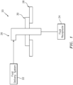
- the assembly 20 of FIG. 1 includes a fluid delivery system 22 (e.g., a fuel system for the turbine engine), a fluid receptacle 24 (e.g., a fuel injector for the turbine engine) and a fluid passage 26.
- This fluid passage 26 fluidly couples the fluid delivery system 22 with the fluid receptacle 24.
- the assembly 20 also includes a support structure 28 and a slider seal 30 configured to provide a compliant seal interface between the support structure 28 and the fluid passage 26 as described below in further detail.
- the support structure 28 may be configured as a pressure vessel for containing pressurized gas (e.g., air) inside the apparatus (e.g., the engine 130) with respect to a surrounding lower outside atmospheric pressure.
- pressurized gas e.g., air
- the fluid passage 26 may be configured from one or more fluid conduits (e.g., rigid pipes and/or flexible hoses); e.g., a linear array of fluidly coupled fluid conduits.
- the portion of the fluid passage 26 shown in FIGS. 2 and 3 includes an exterior fluid conduit 32, an interior fluid conduit 34 and a slider seal fluid conduit 36.
- the slider seal fluid conduit 36 of FIG. 4 includes a first conduit segment 36A and a second conduit segment 36B.
- the first conduit segment 36A may be a length of tubular body that extends longitudinally along a first portion 38A of a longitudinal centerline 38 of the conduit 36 from a distal interior end 40 of the conduit 36 towards (e.g., to) the second conduit segment 36B.
- the first portion 38A of the longitudinal centerline 38 of FIG. 4 is parallel to (e.g., coaxial with) an axis 42 of the slider seal 30.
- the second conduit segment 36B may be another length of tubular body that extends longitudinally along a second portion 38B of the longitudinal centerline 38 of the conduit 36 from a distal exterior end 44 of the conduit 36 towards (e.g., to) the first conduit segment 36A.
- the second portion 38B of the longitudinal centerline 38 may be angularly offset from (e.g., acutely or obtusely angled, or perpendicular to) the axis 42 of the slider seal 30 and/or the first portion 38A of the longitudinal centerline 38.
- the second conduit segment 36B is fluidly is connected to (e.g., formed integral with) the first conduit segment 36A at a corner joint 46; e.g., an elbow joint or fitting.
- the slider seal fluid conduit 36 of FIG. 4 also includes one or more (e.g., annular) flanges 48 and 50 or rims.
- the exterior flange 48 extends circumferentially around the longitudinal centerline 38 and a tubular sidewall of the conduit 36.
- the exterior flange 48 projects radially out from the tubular sidewall to an outer (e.g., peripheral) exterior flange surface 52.
- the interior flange 50 extends circumferentially around the longitudinal centerline 38 and the tubular sidewall.
- the interior flange 50 projects radially out from the tubular sidewall to an outer (e.g., peripheral) interior flange surface 54.
- each of the flange surfaces 52, 54 may have a circular cross-sectional geometry when respectively viewed in a plane perpendicular to the centerline 38 and/or the axis 42.
- the exterior flange 48 of FIG. 4 is arranged between the interior flange 50 and the corner joint 46.
- the interior flange 50 is arranged between the exterior flange 48 and the distal interior end 40 of the conduit 36.
- the support structure 28 may be configured as a turbine engine case; e.g., a tubular casing such as a fan duct case.
- the support structure 28 is configured with a (e.g., stationary) support structure aperture 56 formed by an aperture surface 58.
- This support structure aperture 56 and the aperture surface 58 extend axially along an axis 60 through the support structure 28 between interior and exterior sides of the support structure 28.
- the axis 60 may be parallel to (e.g., coaxial with or non-coaxial with depending upon thermal growth of the assembly 20) the axis 42 of the slider seal 30.
- the support structure aperture 56 and the aperture surface 58 may each have a circular cross-sectional geometry when respectively viewed in a plane perpendicular to the axis 42, 60.
- the slider seal 30 includes a slider seal housing 62, a slider seal washer 64 and a slider seal puck 66; e.g., a tubular puck / bushing. Relative motion, for example in one or more or all directions, between the slider seal fluid conduit 36 and the support structure aperture 56 is accommodated by (a) sliding of the slider seal washer 64 and/or (b) sliding of the slider seal puck 66 relative to the slider seal washer 64.
- the slider seal housing 62 is an annular body (see FIG. 6 ) which extends circumferentially around an axis 68, which may be parallel to (e.g., coaxial with or non-coaxial with depending upon thermal growth of the assembly 20) the axis 42 of the slider seal 30.
- the slider seal housing 62 is configured with a housing bore 70 and a housing counterbore 72.
- the housing bore 70 extends axially along the axis 68 into the housing 62 from an exterior side of the housing to an inner edge of an annular shelf surface 74.
- the housing counterbore 72 extends axially along the axis 68 into the housing 62 from an interior side of the housing to the annular shelf surface 74 and the housing bore 70.
- the housing bore 70 may be formed by a bore surface 76.
- the housing counterbore 72 may be formed by a counterbore surface 78. Referring to FIG. 8 , the housing bore 70 and the associated bore surface 76 and/or the housing counterbore 72 and the associated counterbore surface 78 may each have a circular cross-sectional geometry when respectively viewed in a plane perpendicular to the axis 42, 68.
- the slider seal housing 62 of FIGS. 2 and 3 may also be configured with a (e.g., annular) slot 79.
- This slot 79 projects radially into the slider seal housing 62 from the housing counterbore 72.
- the slot 79 is configured to receive a capture device 80 such as, but not limited to, a retaining ring as shown in FIGS. 2 and 3 .
- the slider seal washer 64 is an annular body which extends circumferentially around an axis 82, which may be parallel to (e.g., coaxial with) the axis 42 of the slider seal 30.
- the slider seal washer 64 extends radially from an inner (e.g., peripheral) washer surface 84 to an outer (e.g., peripheral) washer surface 86.
- Each of these surfaces 84, 86 extends axially along the axis 42, 82 between opposing interior and exterior sides of the slider seal washer 64.
- the inner washer surface 84 extends circumferentially around the axis 42, 82.
- the inner washer surface 84 thereby forms a washer bore 88 axially along the axis 42, 82 through the slider seal washer 64.
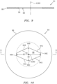
- the inner washer surface 84 has a non-circular cross-sectional geometry (see FIG. 10 ) when viewed in a plane perpendicular to the axis 42, 82.
- This non-circular cross-sectional geometry of FIG. 10 has a minor axis dimension 90 and a major axis dimension 92 that is greater than the minor axis dimension 90.
- minor axis may describe a minimum (shortest) diameter of an elongated shape such as an oval or an ellipse, which diameter extends through a center of the elongated shape.
- major axis may describe a maximum (longest) diameter of an elongated shape such as an oval or an ellipse, which diameter extends through a center of the elongated shape.
- the non-circular cross-sectional geometry for example, may be an oval cross-sectional geometry or a diamond cross-sectional geometry with one or more rounded corners.
- the non-circular cross-sectional geometry includes a plurality of straight side segments 94A-94D and a plurality of curved side segments 96A-96D.
- the first and the second straight side segments 94A and 94B are joined by the first curved side segment 96A at a first corner, where the first and the second straight side segments 94A and 94B are angularly offset by a first acute angle.
- the third and the fourth straight side segments 94C and 94D are joined by the third curved side segment 96C at a third corner, where the third and the fourth straight side segments 94C and 94D are angularly offset by a second acute angle which may be equal to the first acute angle.
- the first and the fourth straight side segments 94A and 94D are joined by the fourth curved side segment 96D at a fourth corner, where the first and the fourth straight side segments 94A and 94D are angularly offset by a first obtuse angle.
- the second and the third straight side segments 94B and 94C are joined by the second curved side segment 96C at a second corner, where the second and the third straight side segments 94B and 94C are angularly offset by a second obtuse angle which may be equal to the first obtuse angle.
- the present disclosure is not limited to the foregoing exemplary non-circular cross-sectional geometry. In other embodiments, for example, the non-circular cross-sectional geometry may have any shape which decreases an area of the geometry relative to a circle; e.g., see dashed line in FIG. 10 .
- the outer washer surface 86 extends circumferentially around the axis 42, 82.
- the outer washer surface 86 may have a circular cross-sectional geometry (see FIG. 10 ) when viewed in a plane perpendicular to the axis 42, 82.
- a shape of the cross-sectional geometry of the outer washer surface 86 may be different than a shape of the non-circular cross-sectional geometry of the inner washer surface 84.
- the slider seal puck 66 is configured with a tubular body.
- the slider seal puck 66 extends axially along an axis 98 between opposing interior and exterior ends 100 and 102, which axis 98 may be parallel to (e.g., coaxial with) the axis 42 of the slider seal 30.
- the slider seal puck 66 extends circumferentially around the axis 42, 98.
- the slider seal puck 66 extends radially from an inner (e.g., peripheral) puck surface 104 to an outer (e.g., peripheral) puck surface 106.
- an inner (e.g., peripheral) puck surface 104 to an outer (e.g., peripheral) puck surface 106.
- the inner puck surface 104 extends axially along the axis 42, 98 between the interior and the exterior ends 100 and 102.
- the outer puck surface 106 extends axially along the axis 42, 98 from the exterior end 102 towards the interior end 100 and, more particularly, to an outer edge of an annular shelf surface 108.
- Another outer surface 110 of the slider seal puck 66 extends axially along the axis 42, 98 from an inner edge of the annular shelf surface 108 to the interior end 100 of the puck 66.
- the inner puck surface 104 extends circumferentially around the axis 42, 98.
- the inner puck surface 104 thereby forms a puck bore 112 axially along the axis 42, 98 through the slider seal puck 66.
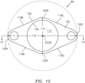
- the inner puck surface 104 has a circular cross-sectional geometry (see FIG. 12 ) when viewed in a plane perpendicular to the axis 42, 98.
- the outer puck surface 106 extends circumferentially around the axis 42, 98.
- the outer puck surface 106 has a non-circular cross-sectional geometry (see FIG. 12 ) when viewed in a plane perpendicular to the axis 42, 98.
- This non-circular cross-sectional geometry is configured to match the non-circular cross-sectional geometry of the inner washer surface 84 (see FIG. 10 ).
- the non-circular cross-sectional geometry of FIG. 12 has a minor axis dimension 114 and a major axis dimension 116 that is greater than the minor axis dimension 114.
- the minor axis dimension 114 may be equal to (or slightly smaller) than the minor axis dimension 90 (see FIG. 10 ).
- the major axis dimension may be equal to (or slightly smaller) than the major axis dimension 92 (see FIG. 10 ).
- the non-circular cross-sectional geometry may be an oval cross-sectional geometry or a diamond cross-sectional geometry with one or more rounded corners.
- a shape of the non-circular cross-sectional geometry of the outer puck surface 106 may be different than a shape of the cross-sectional geometry of the inner puck surface 104.
- the non-circular cross-sectional geometry includes a plurality of straight side segments 118A-D and a plurality of curved side segments 120A-D.
- the first and the second straight side segments 118A and 118B are joined by the first curved side segment 120A at a first corner, where the first and the second straight side segments 118A and 118B are angularly offset by a first acute angle.
- the third and the fourth straight side segments 118C and 118D are joined by the third curved side segment 120C at a third corner, where the third and the fourth straight side segments 118C and 118D are angularly offset by a second acute angle which may be equal to the first acute angle.
- the first and the fourth straight side segments 118A and 118D are joined by the fourth curved side segment 120D at a fourth corner, where the first and the fourth straight side segments 118A and 118D are angularly offset by a first obtuse angle.
- the second and the third straight side segments 118B and 118C are joined by the second curved side segment 120B at a second corner, where the second and the third straight side segments 118B and 118C are angularly offset by a second obtuse angle which may be equal to the first obtuse angle.
- the present disclosure is not limited to the foregoing exemplary non-circular cross-sectional geometry. In other embodiments, for example, the non-circular cross-sectional geometry may have any shape which decreases an area of the geometry relative to a circle; e.g., see dashed line in FIG. 12 .
- the slider seal housing 62 is mounted to the support structure 28.
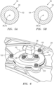
- the slider seal housing 62 may be attached to the support structure 28 by one or more fasteners 122 (e.g., bolts) as shown in FIG. 6 .
- the slider seal washer 64 is nested within the housing counterbore 72 and the slider seal washer 64 is captured within the housing counterbore 72 by the capture device 80; e.g., retaining ring.
- a diameter of the housing counterbore 72 may be greater than a diameter of the outer washer surface 86, which enables the slider seal washer 64 to move radially (e.g., relative to the axis 42) within the housing counterbore 72.
- an axial distance between the capture device 80 and the annular shelf surface 74 may be greater than an axial thickness of the slider seal washer 64, which enables the slider seal washer 64 to move axially (e.g., relative to the axis 42) within the housing counterbore 72. Such movement enables accommodation of dimensional variation due to material thermal expansion.
- the slider seal puck 66 is mated with the slider seal washer 64.
- the slider seal puck 66 is inserted into the washer bore 88 such that the slider seal puck 66 projects axially through the slider seal washer 64.
- the outer puck surface 106 radially sealingly engages (e.g., contacts) the inner washer surface 84, thereby forming a seal interface between the slider seal puck 66 and the slider seal washer 64.
- the outer puck surface 106 is configured to axially slide along the inner washer surface 84, which enables the slider seal puck 66 to move axially (e.g., relative to the axis 42) relative to the slider seal washer 64. Such movement further enables accommodation of dimensional variation due to material thermal expansion.
- the slider seal fluid conduit 36 is mated with the slider seal puck 66.
- the slider seal fluid conduit 36 is inserted into the puck bore 112 such that the slider seal fluid conduit 36 projects axially through the slider seal puck 66.
- Each of the flange surface 52, 54 may radially sealingly engage (e.g., contact) the inner puck surface 104, thereby forming a seal interface between the slider seal puck 66 and the slider seal fluid conduit 36.
- the slider seal fluid conduit 36 is mounted to the slider seal puck 66.
- the slider seal fluid conduit 36 may be fixedly attached to the slider seal puck 66.
- the slider seal fluid conduit 36 is fixedly attached to the slider seal puck 66 via thrust wire 124.
- the present disclosure is not limited to any particular technique or device(s) for fixedly connecting the slider seal fluid conduit 36 to the slider seal puck 66.
- the distal exterior end 44 of the slider seal fluid conduit 36 is fluidly coupled with the exterior fluid conduit 32 (see FIG. 2 ).
- the distal interior end 40 of the slider seal fluid conduit 36 is fluidly coupled with the interior fluid conduit 34 (see FIG. 3 ).
- the distal interior end 34 of the slider seal fluid conduit 36 may be inserted into a receptacle at a distal end of the interior fluid conduit 34.
- the interior fluid conduit 34 may then be attached to the slider seal puck 66 by one or more fasteners 126; e.g., bolts. These fasteners 126 may be torqued to form a seal interface between the fluid conduits 34 and 36.
- the present disclosure is not limited to the foregoing exemplary fluid conduit interconnection technique.
- gas pressure within the support structure 28 may be greater than gas (e.g., air) pressure outside of the support structure 28.
- the slider seal puck 66 may be subject to an outward pressure force (e.g., see pressure force arrow 128) imparting force on the fluid receptacle 24 (see FIG. 1 ). Due to the fixed connection between the slider seal puck 66 and the slider seal fluid conduit 36, the outward pressure force may cause the slider seal puck 66 to pull against the slider seal fluid conduit 36 and, thus, the fluid passage 26 and the components attached thereto. However, this outward pressure force is mitigated by providing the outer puck surface 106 with its non-circular cross-sectional geometry.
- the non-circular cross-sectional geometry has less area than a circular cross-sectional geometry (see dashed line) and, thus, provides the slider seal puck 66 with less surface area against which gas pressure may be exerted, thereby reducing force on the fluid conduit 36 and attached components such as, for example, the fluid receptacle (see FIG. 1 ).
- a relatively small perimeter provided by the non-circular cross-sectional geometry may reduce area for gas leakage relative to a perimeter of a circular cross-sectional geometry.
- the slider seal washer 64 may be constructed from or otherwise include non-metal material such as, but not limited to, fiber-reinforced composite material.
- non-metal material such as, but not limited to, fiber-reinforced composite material.
- present disclosure is not limited to such an exemplary washer material.
- the slider seal puck 66 may be constructed from or otherwise include metal material.
- the present disclosure is not limited to such an exemplary puck material.
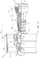
- FIG. 14 is a side cutaway illustration of a geared turbine engine 130 with which the assembly 20 may be included.
- This turbine engine 130 extends along an axial centerline 132 between an upstream airflow inlet 134 and a downstream airflow exhaust 136.
- the turbine engine 130 includes a fan section 138, a compressor section 139, a combustor section 140 and a turbine section 141.
- the compressor section 139 includes a low pressure compressor (LPC) section 139A and a high pressure compressor (HPC) section 139B.
- the turbine section 141 includes a high pressure turbine (HPT) section 141A and a low pressure turbine (LPT) section 141B.
- the engine sections 138-141 are arranged sequentially along the centerline 132 within an engine housing 142, which may include the support structure 28 of FIGS. 2 and 3 .
- the housing 142 of FIG. 14 includes an inner case 144 (e.g., a core case) and an outer case 146 (e.g., a fan case).
- the inner case 144 may house one or more of the engine sections 139-141; e.g., an engine core.
- the outer case 146 may house at least the fan section 138.
- Each of the engine sections 138, 139A, 139B, 141A and 141B includes a respective rotor 148-152.
- Each of these rotors 148-152 includes a plurality of rotor blades arranged circumferentially around and connected to one or more respective rotor disks.
- the rotor blades may be formed integral with or mechanically fastened, welded, brazed, adhered and/or otherwise attached to the respective rotor disk(s).
- the fan rotor 148 is connected to a gear train 154, for example, through a fan shaft 156.
- the gear train 154 and the LPC rotor 149 are connected to and driven by the LPT rotor 152 through a low speed shaft 157.
- the HPC rotor 150 is connected to and driven by the HPT rotor 151 through a high speed shaft 158.
- the shafts 156-158 are rotatably supported by a plurality of bearings 160; e.g., rolling element and/or thrust bearings. Each of these bearings 160 is connected to the engine housing 142 by at least one stationary structure such as, for example, an annular support strut.
- This air is directed through the fan section 138 and into a core gas path 162 and a bypass gas path 164.
- the core gas path 162 extends sequentially through the engine sections 139-141.
- the air within the core gas path 162 may be referred to as "core air”.
- the bypass gas path 164 extends through a bypass duct, which bypasses the engine core.
- the air within the bypass gas path 164 may be referred to as "bypass air”.
- the core air is compressed by the compressor rotors 149 and 150 and directed into a combustion chamber 166 of a combustor in the combustor section 140.
- Fuel is injected into the combustion chamber 166 and mixed with the compressed core air to provide a fuel-air mixture.
- This fuel air mixture is ignited and combustion products thereof flow through and sequentially cause the turbine rotors 151 and 152 to rotate.
- the rotation of the turbine rotors 151 and 152 respectively drive rotation of the compressor rotors 150 and 149 and, thus, compression of the air received from a core airflow inlet.
- the rotation of the turbine rotor 152 also drives rotation of the fan rotor 148, which propels bypass air through and out of the bypass gas path 164.
- the propulsion of the bypass air may account for a majority of thrust generated by the turbine engine 130, e.g., more than seventy-five percent (75%) of engine thrust.
- the turbine engine 130 of the present disclosure is not limited to the foregoing exemplary thrust ratio.
- the assembly 20 and/or its slider seal 30 may be included in various turbine engines other than the one described above as well as in other types of equipment.
- the assembly 20 and/or its slider seal 30, for example, may be included in a geared turbine engine where a gear train connects one or more shafts to one or more rotors in a fan section, a compressor section and/or any other engine section.
- the assembly 20 and/or its slider seal 30 may be included in a turbine engine configured without a gear train.
- the assembly 20 and/or its slider seal 30 may be included in a geared or non-geared turbine engine configured with a single spool, with two spools (e.g., see FIG. 14 ), or with more than two spools.
- the turbine engine may be configured as a turbofan engine, a turbojet engine, a propfan engine, a pusher fan engine or any other type of turbine engine. The present disclosure therefore is not limited to any particular types or configurations of turbine engines or equipment.
Landscapes
- Engineering & Computer Science (AREA)
- General Engineering & Computer Science (AREA)
- Mechanical Engineering (AREA)
- Chemical & Material Sciences (AREA)
- Combustion & Propulsion (AREA)
- Physics & Mathematics (AREA)
- Geometry (AREA)
- Turbine Rotor Nozzle Sealing (AREA)
Description
- This disclosure relates generally to a seal interface and, more particularly, to a slider seal on, for example, a gas turbine engine.
- Apparatuses such as gas turbine engines may include seal interfaces between a stationary structure and an element projecting through an aperture in the stationary structure containing an engine internal pressure. Various types and configurations of seal interfaces such as slider seals are known in the art. While these known seal interfaces have various benefits, there is still room in the art for improvement. There is a need in the art therefore for an improved seal interface system which, for example, may reduce forces on internal components of a gas turbine engine.
-
EP 2 327 858 A2 discloses a prior art composite slider seal for turbojet penetration. -
US 2018/298826 A2 discloses prior art aircraft auxiliary power unit exhaust pipe seals and methods. -
GB 2 038 473 A -
GB 2 461 503 A -
EP 2 042 691 A2 discloses a prior art lubricant pipe assembly for a turbine. - According to an aspect of the present disclosure, an assembly is provided for a turbine engine as recited in
claim 1. - Features of embodiments of the disclosure are set forth in the dependent claims.
- The foregoing features and the operation of the invention will become more apparent in light of the following description and the accompanying drawings.
-
-
FIG. 1 is a schematic illustration of an assembly for an apparatus. -
FIGS. 2 and3 are perspective side sectional illustrations of a portion of the assembly ofFIG. 1 . -
FIG. 4 is a side sectional illustration of a slider seal fluid conduit. -
FIG. 5A is a cross-sectional illustration of the slider seal fluid conduit taken alongline 5A-5A inFIG. 4 . -
FIG. 5B is a cross-sectional illustration of the slider seal fluid conduit taken alongline 5B-5B inFIG. 4 . -
FIG. 6 is a partial exterior view perspective illustration of the assembly portions shown inFIGS. 2 and3 . -
FIG. 7 is a partial exterior view illustration of a support structure. -
FIG. 8 is an interior view illustration of a slider seal housing. -
FIG. 9 is a side sectional illustration of a slider seal washer taken along line 9-9 inFIG. 10 . -
FIG. 10 is an exterior view illustration of the slider seal washer. -
FIG. 11 is a side sectional illustration of a slider seal puck taken along line 11-11 inFIG. 12 . -
FIG. 12 is an exterior view illustration of the slider seal puck. -
FIG. 13 is another perspective sectional illustration of a portion of the assembly ofFIG. 1 . -
FIG. 14 is a side cutaway illustration of a geared turbine engine. -
FIG. 1 is a schematic illustration of anassembly 20 for an apparatus such as, but not limited to, a turbine engine (e.g., seeengine 130 inFIG. 14 ). Examples of such a turbine engine include, but are not limited to, an industrial gas turbine engine and an aerospace gas turbine engine such as, but not limited to, a turbofan, turbojet or turboshaft gas turbine engine. The present disclosure, however, is not limited to turbine engine applications. - The
assembly 20 ofFIG. 1 includes a fluid delivery system 22 (e.g., a fuel system for the turbine engine), a fluid receptacle 24 (e.g., a fuel injector for the turbine engine) and afluid passage 26. Thisfluid passage 26 fluidly couples thefluid delivery system 22 with thefluid receptacle 24. Theassembly 20 also includes asupport structure 28 and aslider seal 30 configured to provide a compliant seal interface between thesupport structure 28 and thefluid passage 26 as described below in further detail. Briefly, thesupport structure 28 may be configured as a pressure vessel for containing pressurized gas (e.g., air) inside the apparatus (e.g., the engine 130) with respect to a surrounding lower outside atmospheric pressure. - Referring to
FIGS. 2 and3 , thefluid passage 26 may be configured from one or more fluid conduits (e.g., rigid pipes and/or flexible hoses); e.g., a linear array of fluidly coupled fluid conduits. The portion of thefluid passage 26 shown inFIGS. 2 and3 , for example, includes anexterior fluid conduit 32, aninterior fluid conduit 34 and a sliderseal fluid conduit 36. - The slider
seal fluid conduit 36 ofFIG. 4 includes afirst conduit segment 36A and asecond conduit segment 36B. Thefirst conduit segment 36A may be a length of tubular body that extends longitudinally along afirst portion 38A of alongitudinal centerline 38 of theconduit 36 from a distalinterior end 40 of theconduit 36 towards (e.g., to) thesecond conduit segment 36B. Thefirst portion 38A of thelongitudinal centerline 38 ofFIG. 4 is parallel to (e.g., coaxial with) anaxis 42 of theslider seal 30. Thesecond conduit segment 36B may be another length of tubular body that extends longitudinally along asecond portion 38B of thelongitudinal centerline 38 of theconduit 36 from a distalexterior end 44 of theconduit 36 towards (e.g., to) thefirst conduit segment 36A. Thesecond portion 38B of thelongitudinal centerline 38 may be angularly offset from (e.g., acutely or obtusely angled, or perpendicular to) theaxis 42 of theslider seal 30 and/or thefirst portion 38A of thelongitudinal centerline 38. Thesecond conduit segment 36B is fluidly is connected to (e.g., formed integral with) thefirst conduit segment 36A at acorner joint 46; e.g., an elbow joint or fitting. - The slider
seal fluid conduit 36 ofFIG. 4 also includes one or more (e.g., annular)flanges exterior flange 48 extends circumferentially around thelongitudinal centerline 38 and a tubular sidewall of theconduit 36. Theexterior flange 48 projects radially out from the tubular sidewall to an outer (e.g., peripheral)exterior flange surface 52. Similarly, theinterior flange 50 extends circumferentially around thelongitudinal centerline 38 and the tubular sidewall. Theinterior flange 50 projects radially out from the tubular sidewall to an outer (e.g., peripheral)interior flange surface 54. Referring toFIGS. 5A and 5B , each of theflange surfaces centerline 38 and/or theaxis 42. - The
exterior flange 48 ofFIG. 4 is arranged between theinterior flange 50 and thecorner joint 46. Theinterior flange 50 is arranged between theexterior flange 48 and the distalinterior end 40 of theconduit 36. - Referring to
FIG. 6 , thesupport structure 28 may be configured as a turbine engine case; e.g., a tubular casing such as a fan duct case. Referring toFIGS. 2 and3 , thesupport structure 28 is configured with a (e.g., stationary)support structure aperture 56 formed by anaperture surface 58. Thissupport structure aperture 56 and theaperture surface 58 extend axially along an axis 60 through thesupport structure 28 between interior and exterior sides of thesupport structure 28. The axis 60 may be parallel to (e.g., coaxial with or non-coaxial with depending upon thermal growth of the assembly 20) theaxis 42 of theslider seal 30. Referring toFIG. 7 , thesupport structure aperture 56 and theaperture surface 58 may each have a circular cross-sectional geometry when respectively viewed in a plane perpendicular to theaxis 42, 60. - Referring to
FIGS. 2 and3 , theslider seal 30 includes aslider seal housing 62, aslider seal washer 64 and aslider seal puck 66; e.g., a tubular puck / bushing. Relative motion, for example in one or more or all directions, between the sliderseal fluid conduit 36 and thesupport structure aperture 56 is accommodated by (a) sliding of theslider seal washer 64 and/or (b) sliding of theslider seal puck 66 relative to theslider seal washer 64. - The
slider seal housing 62 is an annular body (seeFIG. 6 ) which extends circumferentially around an axis 68, which may be parallel to (e.g., coaxial with or non-coaxial with depending upon thermal growth of the assembly 20) theaxis 42 of theslider seal 30. Theslider seal housing 62 is configured with a housing bore 70 and ahousing counterbore 72. The housing bore 70 extends axially along the axis 68 into thehousing 62 from an exterior side of the housing to an inner edge of anannular shelf surface 74. Thehousing counterbore 72 extends axially along the axis 68 into thehousing 62 from an interior side of the housing to theannular shelf surface 74 and the housing bore 70. - The housing bore 70 may be formed by a
bore surface 76. Thehousing counterbore 72 may be formed by acounterbore surface 78. Referring toFIG. 8 , the housing bore 70 and the associatedbore surface 76 and/or thehousing counterbore 72 and the associatedcounterbore surface 78 may each have a circular cross-sectional geometry when respectively viewed in a plane perpendicular to theaxis 42, 68. - The
slider seal housing 62 ofFIGS. 2 and3 may also be configured with a (e.g., annular)slot 79. Thisslot 79 projects radially into theslider seal housing 62 from thehousing counterbore 72. Theslot 79 is configured to receive acapture device 80 such as, but not limited to, a retaining ring as shown inFIGS. 2 and3 . - Referring to
FIGS. 9 and 10 , theslider seal washer 64 is an annular body which extends circumferentially around an axis 82, which may be parallel to (e.g., coaxial with) theaxis 42 of theslider seal 30. Theslider seal washer 64 extends radially from an inner (e.g., peripheral)washer surface 84 to an outer (e.g., peripheral)washer surface 86. Each of thesesurfaces axis 42, 82 between opposing interior and exterior sides of theslider seal washer 64. - The
inner washer surface 84 extends circumferentially around theaxis 42, 82. Theinner washer surface 84 thereby forms a washer bore 88 axially along theaxis 42, 82 through theslider seal washer 64. Theinner washer surface 84 has a non-circular cross-sectional geometry (seeFIG. 10 ) when viewed in a plane perpendicular to theaxis 42, 82. This non-circular cross-sectional geometry ofFIG. 10 has aminor axis dimension 90 and amajor axis dimension 92 that is greater than theminor axis dimension 90. The term "minor axis" may describe a minimum (shortest) diameter of an elongated shape such as an oval or an ellipse, which diameter extends through a center of the elongated shape. The term "major axis" may describe a maximum (longest) diameter of an elongated shape such as an oval or an ellipse, which diameter extends through a center of the elongated shape. The non-circular cross-sectional geometry, for example, may be an oval cross-sectional geometry or a diamond cross-sectional geometry with one or more rounded corners. - In the specific embodiment of
FIG. 10 , the non-circular cross-sectional geometry includes a plurality ofstraight side segments 94A-94D and a plurality ofcurved side segments 96A-96D. The first and the secondstraight side segments curved side segment 96A at a first corner, where the first and the secondstraight side segments straight side segments curved side segment 96C at a third corner, where the third and the fourthstraight side segments straight side segments curved side segment 96D at a fourth corner, where the first and the fourthstraight side segments straight side segments curved side segment 96C at a second corner, where the second and the thirdstraight side segments FIG. 10 . - The
outer washer surface 86 extends circumferentially around theaxis 42, 82. Theouter washer surface 86 may have a circular cross-sectional geometry (seeFIG. 10 ) when viewed in a plane perpendicular to theaxis 42, 82. Thus, a shape of the cross-sectional geometry of theouter washer surface 86 may be different than a shape of the non-circular cross-sectional geometry of theinner washer surface 84. - Referring to
FIGS. 11 and12 , theslider seal puck 66 is configured with a tubular body. Theslider seal puck 66 extends axially along an axis 98 between opposing interior and exterior ends 100 and 102, which axis 98 may be parallel to (e.g., coaxial with) theaxis 42 of theslider seal 30. Theslider seal puck 66 extends circumferentially around theaxis 42, 98. Theslider seal puck 66 extends radially from an inner (e.g., peripheral)puck surface 104 to an outer (e.g., peripheral)puck surface 106. In the specific embodiment ofFIG. 11 , theinner puck surface 104 extends axially along theaxis 42, 98 between the interior and the exterior ends 100 and 102. Theouter puck surface 106 extends axially along theaxis 42, 98 from theexterior end 102 towards theinterior end 100 and, more particularly, to an outer edge of anannular shelf surface 108. Anotherouter surface 110 of theslider seal puck 66 extends axially along theaxis 42, 98 from an inner edge of theannular shelf surface 108 to theinterior end 100 of thepuck 66. - The
inner puck surface 104 extends circumferentially around theaxis 42, 98. Theinner puck surface 104 thereby forms apuck bore 112 axially along theaxis 42, 98 through theslider seal puck 66. Theinner puck surface 104 has a circular cross-sectional geometry (seeFIG. 12 ) when viewed in a plane perpendicular to theaxis 42, 98. - The
outer puck surface 106 extends circumferentially around theaxis 42, 98. Theouter puck surface 106 has a non-circular cross-sectional geometry (seeFIG. 12 ) when viewed in a plane perpendicular to theaxis 42, 98. This non-circular cross-sectional geometry is configured to match the non-circular cross-sectional geometry of the inner washer surface 84 (seeFIG. 10 ). In particular, the non-circular cross-sectional geometry ofFIG. 12 has aminor axis dimension 114 and amajor axis dimension 116 that is greater than theminor axis dimension 114. Theminor axis dimension 114 may be equal to (or slightly smaller) than the minor axis dimension 90 (seeFIG. 10 ). The major axis dimension may be equal to (or slightly smaller) than the major axis dimension 92 (seeFIG. 10 ). The non-circular cross-sectional geometry may be an oval cross-sectional geometry or a diamond cross-sectional geometry with one or more rounded corners. Thus, a shape of the non-circular cross-sectional geometry of theouter puck surface 106 may be different than a shape of the cross-sectional geometry of theinner puck surface 104. - In the specific embodiment of
FIG. 12 , the non-circular cross-sectional geometry includes a plurality ofstraight side segments 118A-D and a plurality ofcurved side segments 120A-D. The first and the secondstraight side segments curved side segment 120A at a first corner, where the first and the secondstraight side segments straight side segments curved side segment 120C at a third corner, where the third and the fourthstraight side segments straight side segments curved side segment 120D at a fourth corner, where the first and the fourthstraight side segments straight side segments curved side segment 120B at a second corner, where the second and the thirdstraight side segments FIG. 12 . - Referring to
FIGS. 2 and3 , theslider seal housing 62 is mounted to thesupport structure 28. For example, theslider seal housing 62 may be attached to thesupport structure 28 by one or more fasteners 122 (e.g., bolts) as shown inFIG. 6 . Theslider seal washer 64 is nested within thehousing counterbore 72 and theslider seal washer 64 is captured within thehousing counterbore 72 by thecapture device 80; e.g., retaining ring. A diameter of thehousing counterbore 72 may be greater than a diameter of theouter washer surface 86, which enables theslider seal washer 64 to move radially (e.g., relative to the axis 42) within thehousing counterbore 72. Furthermore, an axial distance between thecapture device 80 and theannular shelf surface 74 may be greater than an axial thickness of theslider seal washer 64, which enables theslider seal washer 64 to move axially (e.g., relative to the axis 42) within thehousing counterbore 72. Such movement enables accommodation of dimensional variation due to material thermal expansion. - The
slider seal puck 66 is mated with theslider seal washer 64. In particular, theslider seal puck 66 is inserted into the washer bore 88 such that theslider seal puck 66 projects axially through theslider seal washer 64. Theouter puck surface 106 radially sealingly engages (e.g., contacts) theinner washer surface 84, thereby forming a seal interface between theslider seal puck 66 and theslider seal washer 64. Theouter puck surface 106 is configured to axially slide along theinner washer surface 84, which enables theslider seal puck 66 to move axially (e.g., relative to the axis 42) relative to theslider seal washer 64. Such movement further enables accommodation of dimensional variation due to material thermal expansion. - The slider
seal fluid conduit 36 is mated with theslider seal puck 66. In particular, the sliderseal fluid conduit 36 is inserted into the puck bore 112 such that the sliderseal fluid conduit 36 projects axially through theslider seal puck 66. Each of theflange surface inner puck surface 104, thereby forming a seal interface between theslider seal puck 66 and the sliderseal fluid conduit 36. The sliderseal fluid conduit 36 is mounted to theslider seal puck 66. For example, the sliderseal fluid conduit 36 may be fixedly attached to theslider seal puck 66. In the specific embodiment ofFIGS. 2 and3 , the sliderseal fluid conduit 36 is fixedly attached to theslider seal puck 66 viathrust wire 124. The present disclosure, however, is not limited to any particular technique or device(s) for fixedly connecting the sliderseal fluid conduit 36 to theslider seal puck 66. - The distal
exterior end 44 of the sliderseal fluid conduit 36 is fluidly coupled with the exterior fluid conduit 32 (seeFIG. 2 ). The distalinterior end 40 of the sliderseal fluid conduit 36 is fluidly coupled with the interior fluid conduit 34 (seeFIG. 3 ). For example, the distalinterior end 34 of the sliderseal fluid conduit 36 may be inserted into a receptacle at a distal end of the interiorfluid conduit 34. The interiorfluid conduit 34 may then be attached to theslider seal puck 66 by one ormore fasteners 126; e.g., bolts. Thesefasteners 126 may be torqued to form a seal interface between thefluid conduits - Referring to
FIG. 13 , during operation of the turbine engine, gas (e.g., air) pressure within thesupport structure 28 may be greater than gas (e.g., air) pressure outside of thesupport structure 28. As a result, theslider seal puck 66 may be subject to an outward pressure force (e.g., see pressure force arrow 128) imparting force on the fluid receptacle 24 (seeFIG. 1 ). Due to the fixed connection between theslider seal puck 66 and the sliderseal fluid conduit 36, the outward pressure force may cause theslider seal puck 66 to pull against the sliderseal fluid conduit 36 and, thus, thefluid passage 26 and the components attached thereto. However, this outward pressure force is mitigated by providing theouter puck surface 106 with its non-circular cross-sectional geometry. In particular, as described above with respect toFIG. 12 , the non-circular cross-sectional geometry has less area than a circular cross-sectional geometry (see dashed line) and, thus, provides theslider seal puck 66 with less surface area against which gas pressure may be exerted, thereby reducing force on thefluid conduit 36 and attached components such as, for example, the fluid receptacle (seeFIG. 1 ). In addition, a relatively small perimeter provided by the non-circular cross-sectional geometry may reduce area for gas leakage relative to a perimeter of a circular cross-sectional geometry. - In some embodiments, the
slider seal washer 64 may be constructed from or otherwise include non-metal material such as, but not limited to, fiber-reinforced composite material. The present disclosure, however, is not limited to such an exemplary washer material. - In some embodiments, the
slider seal puck 66 may be constructed from or otherwise include metal material. The present disclosure, however, is not limited to such an exemplary puck material. -
FIG. 14 is a side cutaway illustration of a gearedturbine engine 130 with which theassembly 20 may be included. Thisturbine engine 130 extends along anaxial centerline 132 between anupstream airflow inlet 134 and adownstream airflow exhaust 136. Theturbine engine 130 includes afan section 138, acompressor section 139, acombustor section 140 and aturbine section 141. Thecompressor section 139 includes a low pressure compressor (LPC)section 139A and a high pressure compressor (HPC)section 139B. Theturbine section 141 includes a high pressure turbine (HPT)section 141A and a low pressure turbine (LPT)section 141B. - The engine sections 138-141 are arranged sequentially along the
centerline 132 within anengine housing 142, which may include thesupport structure 28 ofFIGS. 2 and3 . Thehousing 142 ofFIG. 14 includes an inner case 144 (e.g., a core case) and an outer case 146 (e.g., a fan case). Theinner case 144 may house one or more of the engine sections 139-141; e.g., an engine core. Theouter case 146 may house at least thefan section 138. - Each of the
engine sections - The
fan rotor 148 is connected to agear train 154, for example, through afan shaft 156. Thegear train 154 and theLPC rotor 149 are connected to and driven by theLPT rotor 152 through alow speed shaft 157. TheHPC rotor 150 is connected to and driven by theHPT rotor 151 through ahigh speed shaft 158. The shafts 156-158 are rotatably supported by a plurality ofbearings 160; e.g., rolling element and/or thrust bearings. Each of thesebearings 160 is connected to theengine housing 142 by at least one stationary structure such as, for example, an annular support strut. - During operation, air enters the
turbine engine 130 through theairflow inlet 134. This air is directed through thefan section 138 and into acore gas path 162 and abypass gas path 164. Thecore gas path 162 extends sequentially through the engine sections 139-141. The air within thecore gas path 162 may be referred to as "core air". Thebypass gas path 164 extends through a bypass duct, which bypasses the engine core. The air within thebypass gas path 164 may be referred to as "bypass air". - The core air is compressed by the
compressor rotors combustion chamber 166 of a combustor in thecombustor section 140. Fuel is injected into thecombustion chamber 166 and mixed with the compressed core air to provide a fuel-air mixture. This fuel air mixture is ignited and combustion products thereof flow through and sequentially cause theturbine rotors turbine rotors compressor rotors turbine rotor 152 also drives rotation of thefan rotor 148, which propels bypass air through and out of thebypass gas path 164. The propulsion of the bypass air may account for a majority of thrust generated by theturbine engine 130, e.g., more than seventy-five percent (75%) of engine thrust. Theturbine engine 130 of the present disclosure, however, is not limited to the foregoing exemplary thrust ratio. - The
assembly 20 and/or itsslider seal 30 may be included in various turbine engines other than the one described above as well as in other types of equipment. Theassembly 20 and/or itsslider seal 30, for example, may be included in a geared turbine engine where a gear train connects one or more shafts to one or more rotors in a fan section, a compressor section and/or any other engine section. Alternatively, theassembly 20 and/or itsslider seal 30 may be included in a turbine engine configured without a gear train. Theassembly 20 and/or itsslider seal 30 may be included in a geared or non-geared turbine engine configured with a single spool, with two spools (e.g., seeFIG. 14 ), or with more than two spools. The turbine engine may be configured as a turbofan engine, a turbojet engine, a propfan engine, a pusher fan engine or any other type of turbine engine. The present disclosure therefore is not limited to any particular types or configurations of turbine engines or equipment. - While various embodiments of the present disclosure have been described, it will be apparent to those of ordinary skill in the art that many more embodiments and implementations are possible within the scope of the disclosure. For example, the present disclosure as described herein includes several aspects and embodiments that include particular features. Although these features may be described individually, it is within the scope of the present disclosure that some or all of these features may be combined with any one of the aspects and remain within the scope of the disclosure. Accordingly, the present disclosure is not to be restricted except in light of the attached claims.
Claims (12)
- An assembly (20) for a turbine engine (130), comprising:a slider seal (30) including a washer (64) and a tubular puck (66);the washer (64) including an inner washer surface (84) and an outer washer surface (86), the inner washer surface (84) extending around an axis (42) of the slider seal (30) and having a non-circular cross-sectional geometry when viewed in a plane perpendicular to the axis (42), the inner washer surface (84) forming a washer bore (88) axially through the washer (64), and the outer washer surface (86) extending around the axis (42) and having a cross-sectional geometry with a shape that is different than a shape of the non-circular cross-sectional geometry; andthe tubular puck (66) projecting axially through the washer bore (88) and including an outer puck surface (106), the outer puck surface (106) extending around the axis (42), and the outer puck surface (106) sealingly engaged with and configured to slide axially along the inner washer surface (84),wherein the tubular puck (66) further includes an inner puck surface (104), and the inner puck surface (104) extends around the axis (42) and forms a puck bore (112) axially through the tubular puck (66),and wherein the inner puck surface (104) has a cross-sectional geometry, when viewed in a plane perpendicular to the axis (42), with a shape that is different than the shape of the non-circular cross-sectional geometry.
- The assembly (20) of claim 1, wherein the non-circular cross-sectional geometry of the inner washer surface (84) is an oval cross-sectional geometry.
- The assembly (20) of claim 1 or 2, wherein the non-circular cross-sectional geometry of the inner washer surface (84) is an elongated cross-sectional geometry with a minor axis dimension (90) and a major axis dimension (92) that is greater than the minor axis dimension (90).
- The assembly (20) of any preceding claim, wherein the cross-sectional geometry of the outer washer surface (86) is a circular cross-sectional geometry.
- The assembly (20) of any preceding claim, further comprising a first conduit (36) projecting axially through the tubular puck (66), the first conduit (36) fixedly attached to and sealingly engaged with the tubular puck (66).
- The assembly (20) of claim 5, further comprising a second conduit (34) fluidly coupled with the first conduit (36), the second conduit (34) connected to the tubular puck (66) by one or more fasteners (126).
- The assembly (20) of claim 5 or 6, further comprising a fluid delivery system (22) for the turbine engine (130), the fluid delivery system (22) configured to direct fluid through the first conduit (36) during operation of the turbine engine (130).
- The assembly (20) of any preceding claim, whereinthe slider seal (30) further includes a housing (62);the housing (62) is configured with a housing bore (70) and a housing counterbore (72);the housing bore (70) has a circular cross-sectional geometry and extends axially along the axis (42);the housing counterbore (72) extends axially along the axis (42) to the housing bore (70); andthe washer (64) is seated in the housing counterbore (72).
- The assembly (20) of claim 8, wherein the washer (64) is configured to move radially and/or axially relative to the axis (42) within the housing counterbore (72).
- The assembly (20) of claim 8 or 9, wherein the washer (64) is captured within the housing counterbore (72) by a retaining ring (80).
- The assembly (20) of any of claims 8 to 10, further comprising:a turbine engine case (28) configured as a pressure vessel for containing pressurize air; anda or the first conduit (36) projecting through and connected to the tubular puck (66);the housing (62) mounted to the turbine engine case (28); andthe slider seal (30) forming a compliant seal interface between the conduit (36) and the turbine engine case (28).
- The assembly (20) of any preceding claim, whereinthe washer (64) comprises fiber-reinforced composite material; andthe tubular puck (66) comprises metal.
Applications Claiming Priority (1)
| Application Number | Priority Date | Filing Date | Title |
|---|---|---|---|
| US16/523,174 US11174948B2 (en) | 2019-07-26 | 2019-07-26 | Slider seal with non-circular puck geometry |
Publications (2)
| Publication Number | Publication Date |
|---|---|
| EP3770504A1 EP3770504A1 (en) | 2021-01-27 |
| EP3770504B1 true EP3770504B1 (en) | 2023-05-03 |
Family
ID=71833274
Family Applications (1)
| Application Number | Title | Priority Date | Filing Date |
|---|---|---|---|
| EP20187988.9A Active EP3770504B1 (en) | 2019-07-26 | 2020-07-27 | Assembly with slider seal having non-circular puck geometry |
Country Status (2)
| Country | Link |
|---|---|
| US (1) | US11174948B2 (en) |
| EP (1) | EP3770504B1 (en) |
Families Citing this family (2)
| Publication number | Priority date | Publication date | Assignee | Title |
|---|---|---|---|---|
| JP2023157148A (en) * | 2022-04-14 | 2023-10-26 | 三菱重工業株式会社 | Fuel supply pipe assembly, gas turbine combustor and gas turbine |
| US12523175B1 (en) * | 2024-12-18 | 2026-01-13 | Pratt & Whitney Canada Corp. | Flame protection seals for gas turbine engines |
Family Cites Families (11)
| Publication number | Priority date | Publication date | Assignee | Title |
|---|---|---|---|---|
| US3793838A (en) | 1972-09-05 | 1974-02-26 | Gen Electric | Augmenter fuel injection mounting system |
| GB2038473B (en) | 1978-12-27 | 1982-12-01 | Lucas Industries Ltd | Fuel injector assembly |
| US7578131B2 (en) | 2005-06-30 | 2009-08-25 | United Technologies Corporation | Augmentor spray bar mounting |
| US8196934B2 (en) * | 2007-01-10 | 2012-06-12 | United Technologies Corporation | Slider seal assembly for gas turbine engine |
| GB2453155A (en) | 2007-09-26 | 2009-04-01 | Rolls Royce Plc | Co-axial pipe assembly which supplies oil to a bearing in a gas turbine engine |
| GB2461503A (en) | 2008-06-30 | 2010-01-06 | Rolls Royce Plc | A sliding joint for a gas turbine engine fuel manifold |
| US8523514B2 (en) | 2009-11-25 | 2013-09-03 | United Technologies Corporation | Composite slider seal for turbojet penetration |
| US9587831B2 (en) * | 2012-11-27 | 2017-03-07 | United Technologies Corporation | Cooled combustor seal |
| GB201506017D0 (en) | 2015-04-09 | 2015-05-27 | Rolls Royce Plc | Fuel injector system |
| CA3060252A1 (en) | 2017-04-18 | 2018-10-25 | Itt Manufacturing Enterprises Llc | Aircraft auxiliary power unit exhaust pipe seals and methods |
| US20200240280A1 (en) * | 2019-01-29 | 2020-07-30 | United Technologies Corporation | Light weight low blockage slider seal |
-
2019
- 2019-07-26 US US16/523,174 patent/US11174948B2/en active Active
-
2020
- 2020-07-27 EP EP20187988.9A patent/EP3770504B1/en active Active
Also Published As
| Publication number | Publication date |
|---|---|
| EP3770504A1 (en) | 2021-01-27 |
| US20210025496A1 (en) | 2021-01-28 |
| US11174948B2 (en) | 2021-11-16 |
Similar Documents
| Publication | Publication Date | Title |
|---|---|---|
| US9033654B2 (en) | Variable geometry vane system for gas turbine engines | |
| US11098652B2 (en) | Isolation seals for gas turbine engines | |
| EP2888463B1 (en) | Annular turbomachine seal and heat shield | |
| US10006568B2 (en) | Double walled tube and manufacture thereof | |
| US10570776B2 (en) | Nozzle for delivering fluid to a component | |
| US10940938B2 (en) | Pitch-changing system equipped with means for lubricating a load-transfer bearing | |
| EP3770504B1 (en) | Assembly with slider seal having non-circular puck geometry | |
| EP4286660A2 (en) | Joint between gas turbine engine components with a spring element | |
| CN111094722B (en) | Dual spool turbojet engine with low pressure shaft thrust bearing in the exhaust casing | |
| EP3730741A1 (en) | Fluid transfer tube with tool receptacle and corresponding assembly | |
| US10746283B2 (en) | Damped fluid transfer tube for a gas turbine engine | |
| US11649729B2 (en) | Anti-vortex tube retaining ring and bore basket | |
| US12018567B2 (en) | Joint between gas turbine engine components with bonded fastener(s) | |
| EP3401515A1 (en) | Turbine vane with inner circumferential anti-rotation features | |
| EP3770476B1 (en) | Compliant jumper tube fitting | |
| US11274770B2 (en) | Monolithic fluid transfer tube | |
| US10670178B2 (en) | Slip joint assembly | |
| EP4707543A1 (en) | Service tube assembly for turbine engine | |
| US12152492B2 (en) | Sealing system including a seal assembly between components | |
| EP3418618A1 (en) | Middle threaded fitting | |
| CN120426132A (en) | Compressor assembly for a gas turbine engine with multi-stage exhaust gas extraction |
Legal Events
| Date | Code | Title | Description |
|---|---|---|---|
| PUAI | Public reference made under article 153(3) epc to a published international application that has entered the european phase |
Free format text: ORIGINAL CODE: 0009012 |
|
| STAA | Information on the status of an ep patent application or granted ep patent |
Free format text: STATUS: THE APPLICATION HAS BEEN PUBLISHED |
|
| AK | Designated contracting states |
Kind code of ref document: A1 Designated state(s): AL AT BE BG CH CY CZ DE DK EE ES FI FR GB GR HR HU IE IS IT LI LT LU LV MC MK MT NL NO PL PT RO RS SE SI SK SM TR |
|
| AX | Request for extension of the european patent |
Extension state: BA ME |
|
| STAA | Information on the status of an ep patent application or granted ep patent |
Free format text: STATUS: REQUEST FOR EXAMINATION WAS MADE |
|
| 17P | Request for examination filed |
Effective date: 20210727 |
|
| RBV | Designated contracting states (corrected) |
Designated state(s): AL AT BE BG CH CY CZ DE DK EE ES FI FR GB GR HR HU IE IS IT LI LT LU LV MC MK MT NL NO PL PT RO RS SE SI SK SM TR |
|
| GRAP | Despatch of communication of intention to grant a patent |
Free format text: ORIGINAL CODE: EPIDOSNIGR1 |
|
| STAA | Information on the status of an ep patent application or granted ep patent |
Free format text: STATUS: GRANT OF PATENT IS INTENDED |
|
| INTG | Intention to grant announced |
Effective date: 20220720 |
|
| GRAJ | Information related to disapproval of communication of intention to grant by the applicant or resumption of examination proceedings by the epo deleted |
Free format text: ORIGINAL CODE: EPIDOSDIGR1 |
|
| STAA | Information on the status of an ep patent application or granted ep patent |
Free format text: STATUS: REQUEST FOR EXAMINATION WAS MADE |
|
| GRAP | Despatch of communication of intention to grant a patent |
Free format text: ORIGINAL CODE: EPIDOSNIGR1 |
|
| STAA | Information on the status of an ep patent application or granted ep patent |
Free format text: STATUS: GRANT OF PATENT IS INTENDED |
|
| INTC | Intention to grant announced (deleted) | ||
| INTG | Intention to grant announced |
Effective date: 20221213 |
|
| GRAS | Grant fee paid |
Free format text: ORIGINAL CODE: EPIDOSNIGR3 |
|
| GRAA | (expected) grant |
Free format text: ORIGINAL CODE: 0009210 |
|
| STAA | Information on the status of an ep patent application or granted ep patent |
Free format text: STATUS: THE PATENT HAS BEEN GRANTED |
|
| AK | Designated contracting states |
Kind code of ref document: B1 Designated state(s): AL AT BE BG CH CY CZ DE DK EE ES FI FR GB GR HR HU IE IS IT LI LT LU LV MC MK MT NL NO PL PT RO RS SE SI SK SM TR |
|
| REG | Reference to a national code |
Ref country code: GB Ref legal event code: FG4D |
|
| REG | Reference to a national code |
Ref country code: AT Ref legal event code: REF Ref document number: 1564885 Country of ref document: AT Kind code of ref document: T Effective date: 20230515 Ref country code: CH Ref legal event code: EP |
|
| REG | Reference to a national code |
Ref country code: DE Ref legal event code: R096 Ref document number: 602020010308 Country of ref document: DE |
|
| REG | Reference to a national code |
Ref country code: IE Ref legal event code: FG4D |
|
| P01 | Opt-out of the competence of the unified patent court (upc) registered |
Effective date: 20230603 |
|
| REG | Reference to a national code |
Ref country code: LT Ref legal event code: MG9D |
|
| REG | Reference to a national code |
Ref country code: NL Ref legal event code: MP Effective date: 20230503 |
|
| REG | Reference to a national code |
Ref country code: AT Ref legal event code: MK05 Ref document number: 1564885 Country of ref document: AT Kind code of ref document: T Effective date: 20230503 |
|
| PG25 | Lapsed in a contracting state [announced via postgrant information from national office to epo] |
Ref country code: SE Free format text: LAPSE BECAUSE OF FAILURE TO SUBMIT A TRANSLATION OF THE DESCRIPTION OR TO PAY THE FEE WITHIN THE PRESCRIBED TIME-LIMIT Effective date: 20230503 Ref country code: PT Free format text: LAPSE BECAUSE OF FAILURE TO SUBMIT A TRANSLATION OF THE DESCRIPTION OR TO PAY THE FEE WITHIN THE PRESCRIBED TIME-LIMIT Effective date: 20230904 Ref country code: NO Free format text: LAPSE BECAUSE OF FAILURE TO SUBMIT A TRANSLATION OF THE DESCRIPTION OR TO PAY THE FEE WITHIN THE PRESCRIBED TIME-LIMIT Effective date: 20230803 Ref country code: NL Free format text: LAPSE BECAUSE OF FAILURE TO SUBMIT A TRANSLATION OF THE DESCRIPTION OR TO PAY THE FEE WITHIN THE PRESCRIBED TIME-LIMIT Effective date: 20230503 Ref country code: ES Free format text: LAPSE BECAUSE OF FAILURE TO SUBMIT A TRANSLATION OF THE DESCRIPTION OR TO PAY THE FEE WITHIN THE PRESCRIBED TIME-LIMIT Effective date: 20230503 Ref country code: AT Free format text: LAPSE BECAUSE OF FAILURE TO SUBMIT A TRANSLATION OF THE DESCRIPTION OR TO PAY THE FEE WITHIN THE PRESCRIBED TIME-LIMIT Effective date: 20230503 |
|
| RAP4 | Party data changed (patent owner data changed or rights of a patent transferred) |
Owner name: RTX CORPORATION |
|
| PG25 | Lapsed in a contracting state [announced via postgrant information from national office to epo] |
Ref country code: RS Free format text: LAPSE BECAUSE OF FAILURE TO SUBMIT A TRANSLATION OF THE DESCRIPTION OR TO PAY THE FEE WITHIN THE PRESCRIBED TIME-LIMIT Effective date: 20230503 Ref country code: PL Free format text: LAPSE BECAUSE OF FAILURE TO SUBMIT A TRANSLATION OF THE DESCRIPTION OR TO PAY THE FEE WITHIN THE PRESCRIBED TIME-LIMIT Effective date: 20230503 Ref country code: LV Free format text: LAPSE BECAUSE OF FAILURE TO SUBMIT A TRANSLATION OF THE DESCRIPTION OR TO PAY THE FEE WITHIN THE PRESCRIBED TIME-LIMIT Effective date: 20230503 Ref country code: LT Free format text: LAPSE BECAUSE OF FAILURE TO SUBMIT A TRANSLATION OF THE DESCRIPTION OR TO PAY THE FEE WITHIN THE PRESCRIBED TIME-LIMIT Effective date: 20230503 Ref country code: IS Free format text: LAPSE BECAUSE OF FAILURE TO SUBMIT A TRANSLATION OF THE DESCRIPTION OR TO PAY THE FEE WITHIN THE PRESCRIBED TIME-LIMIT Effective date: 20230903 Ref country code: HR Free format text: LAPSE BECAUSE OF FAILURE TO SUBMIT A TRANSLATION OF THE DESCRIPTION OR TO PAY THE FEE WITHIN THE PRESCRIBED TIME-LIMIT Effective date: 20230503 Ref country code: GR Free format text: LAPSE BECAUSE OF FAILURE TO SUBMIT A TRANSLATION OF THE DESCRIPTION OR TO PAY THE FEE WITHIN THE PRESCRIBED TIME-LIMIT Effective date: 20230804 |
|
| PG25 | Lapsed in a contracting state [announced via postgrant information from national office to epo] |
Ref country code: FI Free format text: LAPSE BECAUSE OF FAILURE TO SUBMIT A TRANSLATION OF THE DESCRIPTION OR TO PAY THE FEE WITHIN THE PRESCRIBED TIME-LIMIT Effective date: 20230503 |
|
| PG25 | Lapsed in a contracting state [announced via postgrant information from national office to epo] |
Ref country code: SK Free format text: LAPSE BECAUSE OF FAILURE TO SUBMIT A TRANSLATION OF THE DESCRIPTION OR TO PAY THE FEE WITHIN THE PRESCRIBED TIME-LIMIT Effective date: 20230503 |
|
| PG25 | Lapsed in a contracting state [announced via postgrant information from national office to epo] |
Ref country code: SM Free format text: LAPSE BECAUSE OF FAILURE TO SUBMIT A TRANSLATION OF THE DESCRIPTION OR TO PAY THE FEE WITHIN THE PRESCRIBED TIME-LIMIT Effective date: 20230503 Ref country code: SK Free format text: LAPSE BECAUSE OF FAILURE TO SUBMIT A TRANSLATION OF THE DESCRIPTION OR TO PAY THE FEE WITHIN THE PRESCRIBED TIME-LIMIT Effective date: 20230503 Ref country code: RO Free format text: LAPSE BECAUSE OF FAILURE TO SUBMIT A TRANSLATION OF THE DESCRIPTION OR TO PAY THE FEE WITHIN THE PRESCRIBED TIME-LIMIT Effective date: 20230503 Ref country code: EE Free format text: LAPSE BECAUSE OF FAILURE TO SUBMIT A TRANSLATION OF THE DESCRIPTION OR TO PAY THE FEE WITHIN THE PRESCRIBED TIME-LIMIT Effective date: 20230503 Ref country code: DK Free format text: LAPSE BECAUSE OF FAILURE TO SUBMIT A TRANSLATION OF THE DESCRIPTION OR TO PAY THE FEE WITHIN THE PRESCRIBED TIME-LIMIT Effective date: 20230503 Ref country code: CZ Free format text: LAPSE BECAUSE OF FAILURE TO SUBMIT A TRANSLATION OF THE DESCRIPTION OR TO PAY THE FEE WITHIN THE PRESCRIBED TIME-LIMIT Effective date: 20230503 |
|
| REG | Reference to a national code |
Ref country code: DE Ref legal event code: R097 Ref document number: 602020010308 Country of ref document: DE |
|
| PG25 | Lapsed in a contracting state [announced via postgrant information from national office to epo] |
Ref country code: MC Free format text: LAPSE BECAUSE OF FAILURE TO SUBMIT A TRANSLATION OF THE DESCRIPTION OR TO PAY THE FEE WITHIN THE PRESCRIBED TIME-LIMIT Effective date: 20230503 |
|
| PG25 | Lapsed in a contracting state [announced via postgrant information from national office to epo] |
Ref country code: MC Free format text: LAPSE BECAUSE OF FAILURE TO SUBMIT A TRANSLATION OF THE DESCRIPTION OR TO PAY THE FEE WITHIN THE PRESCRIBED TIME-LIMIT Effective date: 20230503 |
|
| REG | Reference to a national code |
Ref country code: CH Ref legal event code: PL |
|
| PLBE | No opposition filed within time limit |
Free format text: ORIGINAL CODE: 0009261 |
|
| STAA | Information on the status of an ep patent application or granted ep patent |
Free format text: STATUS: NO OPPOSITION FILED WITHIN TIME LIMIT |
|
| REG | Reference to a national code |
Ref country code: BE Ref legal event code: MM Effective date: 20230731 |
|
| PG25 | Lapsed in a contracting state [announced via postgrant information from national office to epo] |
Ref country code: LU Free format text: LAPSE BECAUSE OF NON-PAYMENT OF DUE FEES Effective date: 20230727 |
|
| PG25 | Lapsed in a contracting state [announced via postgrant information from national office to epo] |
Ref country code: LU Free format text: LAPSE BECAUSE OF NON-PAYMENT OF DUE FEES Effective date: 20230727 |
|
| 26N | No opposition filed |
Effective date: 20240206 |
|
| REG | Reference to a national code |
Ref country code: IE Ref legal event code: MM4A |
|
| PG25 | Lapsed in a contracting state [announced via postgrant information from national office to epo] |
Ref country code: CH Free format text: LAPSE BECAUSE OF NON-PAYMENT OF DUE FEES Effective date: 20230731 |
|
| PG25 | Lapsed in a contracting state [announced via postgrant information from national office to epo] |
Ref country code: SI Free format text: LAPSE BECAUSE OF FAILURE TO SUBMIT A TRANSLATION OF THE DESCRIPTION OR TO PAY THE FEE WITHIN THE PRESCRIBED TIME-LIMIT Effective date: 20230503 |
|
| PG25 | Lapsed in a contracting state [announced via postgrant information from national office to epo] |
Ref country code: SI Free format text: LAPSE BECAUSE OF FAILURE TO SUBMIT A TRANSLATION OF THE DESCRIPTION OR TO PAY THE FEE WITHIN THE PRESCRIBED TIME-LIMIT Effective date: 20230503 Ref country code: IT Free format text: LAPSE BECAUSE OF FAILURE TO SUBMIT A TRANSLATION OF THE DESCRIPTION OR TO PAY THE FEE WITHIN THE PRESCRIBED TIME-LIMIT Effective date: 20230503 Ref country code: BE Free format text: LAPSE BECAUSE OF NON-PAYMENT OF DUE FEES Effective date: 20230731 |
|
| PG25 | Lapsed in a contracting state [announced via postgrant information from national office to epo] |
Ref country code: IE Free format text: LAPSE BECAUSE OF NON-PAYMENT OF DUE FEES Effective date: 20230727 |
|
| PG25 | Lapsed in a contracting state [announced via postgrant information from national office to epo] |
Ref country code: IE Free format text: LAPSE BECAUSE OF NON-PAYMENT OF DUE FEES Effective date: 20230727 |
|
| PG25 | Lapsed in a contracting state [announced via postgrant information from national office to epo] |
Ref country code: BG Free format text: LAPSE BECAUSE OF FAILURE TO SUBMIT A TRANSLATION OF THE DESCRIPTION OR TO PAY THE FEE WITHIN THE PRESCRIBED TIME-LIMIT Effective date: 20230503 |
|
| PG25 | Lapsed in a contracting state [announced via postgrant information from national office to epo] |
Ref country code: BG Free format text: LAPSE BECAUSE OF FAILURE TO SUBMIT A TRANSLATION OF THE DESCRIPTION OR TO PAY THE FEE WITHIN THE PRESCRIBED TIME-LIMIT Effective date: 20230503 |
|
| PGFP | Annual fee paid to national office [announced via postgrant information from national office to epo] |
Ref country code: GB Payment date: 20250619 Year of fee payment: 6 |
|
| PGFP | Annual fee paid to national office [announced via postgrant information from national office to epo] |
Ref country code: FR Payment date: 20250620 Year of fee payment: 6 |
|
| PG25 | Lapsed in a contracting state [announced via postgrant information from national office to epo] |
Ref country code: CY Free format text: LAPSE BECAUSE OF FAILURE TO SUBMIT A TRANSLATION OF THE DESCRIPTION OR TO PAY THE FEE WITHIN THE PRESCRIBED TIME-LIMIT; INVALID AB INITIO Effective date: 20200727 |
|
| PG25 | Lapsed in a contracting state [announced via postgrant information from national office to epo] |
Ref country code: HU Free format text: LAPSE BECAUSE OF FAILURE TO SUBMIT A TRANSLATION OF THE DESCRIPTION OR TO PAY THE FEE WITHIN THE PRESCRIBED TIME-LIMIT; INVALID AB INITIO Effective date: 20200727 |
|
| REG | Reference to a national code |
Ref country code: DE Ref legal event code: R081 Ref document number: 602020010308 Country of ref document: DE Owner name: RTX CORPORATION (N.D.GES.D. STAATES DELAWARE),, US Free format text: FORMER OWNER: RAYTHEON TECHNOLOGIES CORPORATION, FARMINGTON, CT, US |
|
| PGFP | Annual fee paid to national office [announced via postgrant information from national office to epo] |
Ref country code: DE Payment date: 20250620 Year of fee payment: 6 |
|
| PG25 | Lapsed in a contracting state [announced via postgrant information from national office to epo] |
Ref country code: TR Free format text: LAPSE BECAUSE OF FAILURE TO SUBMIT A TRANSLATION OF THE DESCRIPTION OR TO PAY THE FEE WITHIN THE PRESCRIBED TIME-LIMIT Effective date: 20230503 |