EP3770478A1 - Valve guide with integral assembly support - Google Patents
Valve guide with integral assembly support Download PDFInfo
- Publication number
- EP3770478A1 EP3770478A1 EP20188010.1A EP20188010A EP3770478A1 EP 3770478 A1 EP3770478 A1 EP 3770478A1 EP 20188010 A EP20188010 A EP 20188010A EP 3770478 A1 EP3770478 A1 EP 3770478A1
- Authority
- EP
- European Patent Office
- Prior art keywords
- valve guide
- collar
- coupling
- valve
- circular
- Prior art date
- Legal status (The legal status is an assumption and is not a legal conclusion. Google has not performed a legal analysis and makes no representation as to the accuracy of the status listed.)
- Granted
Links
Images



Classifications
-
- F—MECHANICAL ENGINEERING; LIGHTING; HEATING; WEAPONS; BLASTING
- F16—ENGINEERING ELEMENTS AND UNITS; GENERAL MEASURES FOR PRODUCING AND MAINTAINING EFFECTIVE FUNCTIONING OF MACHINES OR INSTALLATIONS; THERMAL INSULATION IN GENERAL
- F16L—PIPES; JOINTS OR FITTINGS FOR PIPES; SUPPORTS FOR PIPES, CABLES OR PROTECTIVE TUBING; MEANS FOR THERMAL INSULATION IN GENERAL
- F16L37/00—Couplings of the quick-acting type
- F16L37/22—Couplings of the quick-acting type in which the connection is maintained by means of balls, rollers or helical springs under radial pressure between the parts
-
- F—MECHANICAL ENGINEERING; LIGHTING; HEATING; WEAPONS; BLASTING
- F16—ENGINEERING ELEMENTS AND UNITS; GENERAL MEASURES FOR PRODUCING AND MAINTAINING EFFECTIVE FUNCTIONING OF MACHINES OR INSTALLATIONS; THERMAL INSULATION IN GENERAL
- F16L—PIPES; JOINTS OR FITTINGS FOR PIPES; SUPPORTS FOR PIPES, CABLES OR PROTECTIVE TUBING; MEANS FOR THERMAL INSULATION IN GENERAL
- F16L37/00—Couplings of the quick-acting type
- F16L37/28—Couplings of the quick-acting type with fluid cut-off means
- F16L37/30—Couplings of the quick-acting type with fluid cut-off means with fluid cut-off means in each of two pipe-end fittings
- F16L37/32—Couplings of the quick-acting type with fluid cut-off means with fluid cut-off means in each of two pipe-end fittings at least one of two lift valves being opened automatically when the coupling is applied
-
- F—MECHANICAL ENGINEERING; LIGHTING; HEATING; WEAPONS; BLASTING
- F16—ENGINEERING ELEMENTS AND UNITS; GENERAL MEASURES FOR PRODUCING AND MAINTAINING EFFECTIVE FUNCTIONING OF MACHINES OR INSTALLATIONS; THERMAL INSULATION IN GENERAL
- F16L—PIPES; JOINTS OR FITTINGS FOR PIPES; SUPPORTS FOR PIPES, CABLES OR PROTECTIVE TUBING; MEANS FOR THERMAL INSULATION IN GENERAL
- F16L37/00—Couplings of the quick-acting type
- F16L37/28—Couplings of the quick-acting type with fluid cut-off means
- F16L37/38—Couplings of the quick-acting type with fluid cut-off means with fluid cut-off means in only one of two pipe-end fittings
- F16L37/40—Couplings of the quick-acting type with fluid cut-off means with fluid cut-off means in only one of two pipe-end fittings with a lift valve being opened automatically when the coupling is applied
-
- B—PERFORMING OPERATIONS; TRANSPORTING
- B33—ADDITIVE MANUFACTURING TECHNOLOGY
- B33Y—ADDITIVE MANUFACTURING, i.e. MANUFACTURING OF THREE-DIMENSIONAL [3D] OBJECTS BY ADDITIVE DEPOSITION, ADDITIVE AGGLOMERATION OR ADDITIVE LAYERING, e.g. BY 3D PRINTING, STEREOLITHOGRAPHY OR SELECTIVE LASER SINTERING
- B33Y80/00—Products made by additive manufacturing
-
- F—MECHANICAL ENGINEERING; LIGHTING; HEATING; WEAPONS; BLASTING
- F01—MACHINES OR ENGINES IN GENERAL; ENGINE PLANTS IN GENERAL; STEAM ENGINES
- F01L—CYCLICALLY OPERATING VALVES FOR MACHINES OR ENGINES
- F01L3/00—Lift-valve, i.e. cut-off apparatus with closure members having at least a component of their opening and closing motion perpendicular to the closing faces; Parts or accessories thereof
- F01L3/08—Valves guides; Sealing of valve stem, e.g. sealing by lubricant
-
- F—MECHANICAL ENGINEERING; LIGHTING; HEATING; WEAPONS; BLASTING
- F16—ENGINEERING ELEMENTS AND UNITS; GENERAL MEASURES FOR PRODUCING AND MAINTAINING EFFECTIVE FUNCTIONING OF MACHINES OR INSTALLATIONS; THERMAL INSULATION IN GENERAL
- F16K—VALVES; TAPS; COCKS; ACTUATING-FLOATS; DEVICES FOR VENTING OR AERATING
- F16K15/00—Check valves
- F16K15/02—Check valves with guided rigid valve members
- F16K15/025—Check valves with guided rigid valve members the valve being loaded by a spring
- F16K15/026—Check valves with guided rigid valve members the valve being loaded by a spring the valve member being a movable body around which the medium flows when the valve is open
-
- Y—GENERAL TAGGING OF NEW TECHNOLOGICAL DEVELOPMENTS; GENERAL TAGGING OF CROSS-SECTIONAL TECHNOLOGIES SPANNING OVER SEVERAL SECTIONS OF THE IPC; TECHNICAL SUBJECTS COVERED BY FORMER USPC CROSS-REFERENCE ART COLLECTIONS [XRACs] AND DIGESTS
- Y10—TECHNICAL SUBJECTS COVERED BY FORMER USPC
- Y10T—TECHNICAL SUBJECTS COVERED BY FORMER US CLASSIFICATION
- Y10T137/00—Fluid handling
- Y10T137/7722—Line condition change responsive valves
- Y10T137/7837—Direct response valves [i.e., check valve type]
- Y10T137/7904—Reciprocating valves
- Y10T137/7922—Spring biased
- Y10T137/7929—Spring coaxial with valve
- Y10T137/7932—Valve stem extends through fixed spring abutment
-
- Y—GENERAL TAGGING OF NEW TECHNOLOGICAL DEVELOPMENTS; GENERAL TAGGING OF CROSS-SECTIONAL TECHNOLOGIES SPANNING OVER SEVERAL SECTIONS OF THE IPC; TECHNICAL SUBJECTS COVERED BY FORMER USPC CROSS-REFERENCE ART COLLECTIONS [XRACs] AND DIGESTS
- Y10—TECHNICAL SUBJECTS COVERED BY FORMER USPC
- Y10T—TECHNICAL SUBJECTS COVERED BY FORMER US CLASSIFICATION
- Y10T137/00—Fluid handling
- Y10T137/7722—Line condition change responsive valves
- Y10T137/7837—Direct response valves [i.e., check valve type]
- Y10T137/7904—Reciprocating valves
- Y10T137/7922—Spring biased
- Y10T137/7929—Spring coaxial with valve
- Y10T137/7932—Valve stem extends through fixed spring abutment
- Y10T137/7933—Yoke or cage-type support for valve stem
Definitions
- the present disclosure generally relates to valve guides, including valve guides that may be used in connection with a male half of a quick disconnect or a female half of a quick disconnect coupling (QD).
- QD quick disconnect coupling
- valve guides that are used in male halves of quick disconnects often do not incorporate features to provide support of a valve retention collar during initial assembly. Such valve guides commonly require the use of an installation or assembly tool, which is usually used for installation from the backside of the quick disconnect.
- the quick disconnect would be desirable to eliminate the need for an installation or assembly tool, and without affecting the size of the quick disconnect. It would further be desirable to allow the quick disconnect to be used with elbow assemblies using one-piece, unitary bodies, and further to have the ability to connect to quick disconnects of the same style without being affected.
- the ability to form a one-piece, unitary component/body can eliminate the need for multi-piece bodies having or requiring an elastomeric seal between components. Further, such a one-piece, unitary component can save cost and/or weight, and may eliminate potential leak paths.
- the use of a one-piece, unitary component/body can save cost and weight and may eliminate potential leak paths.
- Embodiments of the novel valve guides may be designed or configured to avoid a need to change external dimensions used with existing QDs, so connectivity to QDs of the same or similar type/style is not materially affected.
- a valve guide for a coupling including a circular, longitudinally extending portion, including a substantially circular channel extending therethrough; a ring portion; a plurality of ports radially disposed around a centerline of the valve guide; and one of more collar supports disposed radially about the circular, longitudinally extending portion.
- the valve guide comprises a unitary one-piece component.
- a male portion for a coupling that includes a valve guide with integral assembly support and a method for assembling a coupling assembly are also disclosed.
- FIG. 1 generally illustrates a perspective view of an embodiment of a valve guide 10.
- a valve guide 10 may include inter alia, a circular, longitudinally extending portion 20, which includes a substantially circular channel 22 extending therethrough; a plurality of ports 30 (which may be radially disposed around a centerline of the guide 10 and/or the extending portion 20); one or more collar supports 40, each may further include a collar support pad 50, and a ring portion (or outer circular portion) 60.
- the one or more collar supports 40 are integral with the valve guide and may be configured to, inter alia, to provide assembly support.
- the one or more collar supports may extend in a longitudinal direction (e.g., in a direction of centerline CL).
- Embodiments of a valve guide 10 may comprise a variety of shape and size modifications (including variations from that depicted), and may be comprised of one or more various materials.
- valve guides 10 may be formed as a single, unitary component, which may be formed from a common material.
- Such single, unitary components may be formed as a one-piece component, which may comprise a metal or a plastic material, and may, if desired, be formed via additive manufacturing.
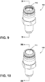
- FIGS. 9 and 10 generally illustrate an embodiment of a male portion 100 for a coupling assembly, such as a quick disconnect assembly.
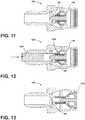
- FIGS. 11 and 13 generally illustrate cross sectional views of an embodiment of the male portion 100.
- a male portion 100 may include a valve guide 10' and a valve 110.
- FIGS. 9 and 11 generally illustrate a valve 110 in a first (or open) position/configuration
- FIGS. 10 and 13 generally illustrate a valve 110 in a second (or closed) position/configuration.
- FIG. 12 generally illustrates the use of a tool 130, and a manner in which it may be used in connection with a male portion 100 and a valve guide more in the nature of that shown in FIG. 1 .
- a tool 130 would need to be inserted from a backside of a quick disconnect coupling component, and through guide ports, in order to provide support to collar 120 while it is positioned (e.g., snapped) over a valve during assembly.
- a tool can be challenging to work with, may be thin, and/or may be prone to damage or may damage components within the male portion 100 when inserted or removed.
- embodiments of the disclosed valve guide 10, including those illustrated herein may eliminate the need for such a tool.
- associated housings may be made into or with elbows, or may be manipulated (e.g., dropped down) to a smaller size without affecting the ability to position (e.g., snap) the collar over the valve to retain it in the male portion/assembly (as no separate tool insertion is required).
- FIG. 14 generally depicts an exploded perspective view of a male portion 100 for a coupling assembly according to teachings of the present disclosure.
- the male portion may include, inter alia, a valve guide 10, a valve 110, a collar 120, a spring 140 (which may provide a biasing force), and a housing 150.
- references to a single element are not necessarily so limited and may include one or more of such element.
- Any directional references e.g., plus, minus, upper, lower, upward, downward, left, right, leftward, rightward, top, bottom, above, below, vertical, horizontal, clockwise, and counterclockwise
- Any directional references are only used for identification purposes to aid the reader's understanding of the present disclosure, and do not create limitations, particularly as to the position, orientation, or use of examples/embodiments.
- joinder references are to be construed broadly and may include intermediate members between a connection of elements and relative movement between elements. As such, joinder references do not necessarily imply that two elements are directly connected/coupled and in fixed relation to each other.
- the use of "e.g.” in the specification is to be construed broadly and is used to provide non-limiting examples of embodiments of the disclosure, and the disclosure is not limited to such examples.
- Uses of "and” and “or” are to be construed broadly (e.g., to be treated as "and/or”). For example and without limitation, uses of "and” do not necessarily require all elements or features listed, and uses of "or” are inclusive unless such a construction would be illogical.
Landscapes
- Engineering & Computer Science (AREA)
- General Engineering & Computer Science (AREA)
- Mechanical Engineering (AREA)
- Quick-Acting Or Multi-Walled Pipe Joints (AREA)
Abstract
Description
- This application claims the benefit of United States Provisional Patent Application Serial No.
62/878,427, filed on July 25, 2019 - The present disclosure generally relates to valve guides, including valve guides that may be used in connection with a male half of a quick disconnect or a female half of a quick disconnect coupling (QD).
- This background description is set forth below for the purpose of providing context only. Therefore, any aspect of this background description, to the extent that it does not otherwise qualify as prior art, is neither expressly nor impliedly admitted as prior art against the instant disclosure.
- Conventional valve guides that are used in male halves of quick disconnects often do not incorporate features to provide support of a valve retention collar during initial assembly. Such valve guides commonly require the use of an installation or assembly tool, which is usually used for installation from the backside of the quick disconnect.
- Among other things, it would be desirable to eliminate the need for an installation or assembly tool, and without affecting the size of the quick disconnect. It would further be desirable to allow the quick disconnect to be used with elbow assemblies using one-piece, unitary bodies, and further to have the ability to connect to quick disconnects of the same style without being affected. The ability to form a one-piece, unitary component/body can eliminate the need for multi-piece bodies having or requiring an elastomeric seal between components. Further, such a one-piece, unitary component can save cost and/or weight, and may eliminate potential leak paths.
- There is a desire for solutions/options that minimize or eliminate one or more challenges or shortcomings of valve guides and fluid couplings. The foregoing discussion is intended only to illustrate examples of the present field and is not a disavowal of scope.
- Among other things, the use of a one-piece, unitary component/body can save cost and weight and may eliminate potential leak paths. Embodiments of the novel valve guides may be designed or configured to avoid a need to change external dimensions used with existing QDs, so connectivity to QDs of the same or similar type/style is not materially affected.
- In embodiments, a valve guide for a coupling including a circular, longitudinally extending portion, including a substantially circular channel extending therethrough; a ring portion; a plurality of ports radially disposed around a centerline of the valve guide; and one of more collar supports disposed radially about the circular, longitudinally extending portion. The valve guide comprises a unitary one-piece component. A male portion for a coupling that includes a valve guide with integral assembly support and a method for assembling a coupling assembly are also disclosed.
- The foregoing and other potential aspects, features, details, utilities, and/or advantages of examples/embodiments of the present disclosure will be apparent from reading the following description, and from reviewing the accompanying drawings.
- While the claims are not limited to a specific illustration, an appreciation of various aspects may be gained through a discussion of various examples. The drawings are not necessarily to scale, and certain features may be exaggerated or hidden to better illustrate and explain an innovative aspect of an example. Further, the exemplary illustrations described herein are not exhaustive or otherwise limiting, and are not restricted to the precise form and configuration shown in the drawings or disclosed in the following detailed description. Exemplary illustrations are described in detail by referring to the drawings as follows:
-
FIG. 1 is a perspective view generally illustrating an embodiment of a more conventional valve guide. -
FIG. 2 is a perspective view generally illustrating another embodiment of a valve guide according to teachings of the present disclosure. -
FIG. 3 is a top view generally illustrating an embodiment of a valve guide such as shown inFIG. 2 . -
FIG. 4 is a bottom view generally illustrating an embodiment of a valve guide such as shown inFIG. 2 . -
FIGS. 5-8 are left, right, rear, and front side views, respectively, generally illustrating an embodiment of a valve guide such as shown inFIG. 2 . -
FIGS. 9 and 10 are perspective views generally illustrating an embodiment of a male portion for a coupling assembly according to teachings of the present disclosure. -
FIG. 11 is a cross sectional view of the male portion shown inFIG. 9 . -
FIG. 12 is a cross sectional view similar to that shown inFIG. 11 , generally illustrated with a partial insertion of an associated tool component. -
FIG. 13 is a cross sectional view of the male portion shown inFIG. 10 . -
FIG. 14 is an exploded perspective view generally illustrating an embodiment of a male portion for a coupling assembly according to teachings of the present disclosure. - Reference will now be made in detail to embodiments of the present disclosure, examples of which are described herein and illustrated in the accompanying drawings. While the present disclosure will be described in conjunction with embodiments and/or examples, they do not limit the present disclosure to these embodiments and/or examples. On the contrary, the present disclosure covers alternatives, modifications, and equivalents.
-
FIG. 1 generally illustrates a perspective view of an embodiment of avalve guide 10. - Another embodiment of a
valve guide 10, with an integral assembly support, is generally illustrated inFIG. 2 . In embodiments, such as generally illustrated inFIG. 2 , avalve guide 10 may include inter alia, a circular, longitudinally extendingportion 20, which includes a substantiallycircular channel 22 extending therethrough; a plurality of ports 30 (which may be radially disposed around a centerline of theguide 10 and/or the extending portion 20); one or more collar supports 40, each may further include acollar support pad 50, and a ring portion (or outer circular portion) 60. The one or more collar supports 40 are integral with the valve guide and may be configured to, inter alia, to provide assembly support. In embodiments, the one or more collar supports may extend in a longitudinal direction (e.g., in a direction of centerline CL). Embodiments of avalve guide 10 may comprise a variety of shape and size modifications (including variations from that depicted), and may be comprised of one or more various materials. - Moreover, embodiments of
valve guides 10, such as disclosed herein, may be formed as a single, unitary component, which may be formed from a common material. Such single, unitary components may be formed as a one-piece component, which may comprise a metal or a plastic material, and may, if desired, be formed via additive manufacturing. -
FIGS. 9 and 10 generally illustrate an embodiment of amale portion 100 for a coupling assembly, such as a quick disconnect assembly.FIGS. 11 and 13 generally illustrate cross sectional views of an embodiment of themale portion 100. As generally illustrated, inFIGS. 9- 11, amale portion 100 may include a valve guide 10' and avalve 110.FIGS. 9 and11 generally illustrate avalve 110 in a first (or open) position/configuration, andFIGS. 10 and13 generally illustrate avalve 110 in a second (or closed) position/configuration. -
FIG. 12 generally illustrates the use of atool 130, and a manner in which it may be used in connection with amale portion 100 and a valve guide more in the nature of that shown inFIG. 1 . In general, such atool 130 would need to be inserted from a backside of a quick disconnect coupling component, and through guide ports, in order to provide support to collar 120 while it is positioned (e.g., snapped) over a valve during assembly. However, such a tool can be challenging to work with, may be thin, and/or may be prone to damage or may damage components within themale portion 100 when inserted or removed. In contrast, embodiments of the disclosedvalve guide 10, including those illustrated herein, may eliminate the need for such a tool. Moreover, associated housings (e.g., housing 150) may be made into or with elbows, or may be manipulated (e.g., dropped down) to a smaller size without affecting the ability to position (e.g., snap) the collar over the valve to retain it in the male portion/assembly (as no separate tool insertion is required). -
FIG. 14 generally depicts an exploded perspective view of amale portion 100 for a coupling assembly according to teachings of the present disclosure. As generally illustrated, the male portion may include, inter alia, avalve guide 10, avalve 110, acollar 120, a spring 140 (which may provide a biasing force), and ahousing 150. - Various examples/embodiments are described herein for various apparatuses, systems, and/or methods. Numerous specific details are set forth to provide a thorough understanding of the overall structure, function, manufacture, and use of the examples/embodiments as described in the specification and illustrated in the accompanying drawings. It will be understood by those skilled in the art, however, that the examples/embodiments may be practiced without such specific details. In other instances, well-known operations, components, and elements have not been described in detail so as not to obscure the examples/embodiments described in the specification. Those of ordinary skill in the art will understand that the examples/embodiments described and illustrated herein are non-limiting examples, and thus it can be appreciated that the specific structural and functional details disclosed herein may be representative and do not necessarily limit the scope of the embodiments.
- Reference throughout the specification to "examples, "in examples," "with examples," "various embodiments," "with embodiments," "in embodiments," or "an embodiment," or the like, means that a particular feature, structure, or characteristic described in connection with the example/embodiment is included in at least one embodiment. Thus, appearances of the phrases "examples, "in examples," "with examples," "in various embodiments," "with embodiments," "in embodiments," or "an embodiment," or the like, in places throughout the specification are not necessarily all referring to the same embodiment. Furthermore, the particular features, structures, or characteristics may be combined in any suitable manner in one or more examples/embodiments. Thus, the particular features, structures, or characteristics illustrated or described in connection with one embodiment/example may be combined, in whole or in part, with the features, structures, functions, and/or characteristics of one or more other embodiments/examples without limitation given that such combination is not illogical or non-functional. Moreover, many modifications may be made to adapt a particular situation or material to the teachings of the present disclosure without departing from the scope thereof.
- It should be understood that references to a single element are not necessarily so limited and may include one or more of such element. Any directional references (e.g., plus, minus, upper, lower, upward, downward, left, right, leftward, rightward, top, bottom, above, below, vertical, horizontal, clockwise, and counterclockwise) are only used for identification purposes to aid the reader's understanding of the present disclosure, and do not create limitations, particularly as to the position, orientation, or use of examples/embodiments.
- Joinder references (e.g., attached, coupled, connected, and the like) are to be construed broadly and may include intermediate members between a connection of elements and relative movement between elements. As such, joinder references do not necessarily imply that two elements are directly connected/coupled and in fixed relation to each other. The use of "e.g." in the specification is to be construed broadly and is used to provide non-limiting examples of embodiments of the disclosure, and the disclosure is not limited to such examples. Uses of "and" and "or" are to be construed broadly (e.g., to be treated as "and/or"). For example and without limitation, uses of "and" do not necessarily require all elements or features listed, and uses of "or" are inclusive unless such a construction would be illogical.
- While processes, systems, and methods may be described herein in connection with one or more steps in a particular sequence, it should be understood that such methods may be practiced with the steps in a different order, with certain steps performed simultaneously, with additional steps, and/or with certain described steps omitted.
- All matter contained in the above description or shown in the accompanying drawings shall be interpreted as illustrative only and not limiting. Changes in detail or structure may be made without departing from the present disclosure.
Claims (15)
- A valve guide for a coupling, comprising:a circular, longitudinally extending portion, including a substantially circular channel extending therethrough;a ring portion;a plurality of ports radially disposed around a centerline of the valve guide; andone of more collar supports disposed radially about the circular, longitudinally extending portion;wherein the valve guide comprises a unitary one-piece component.
- The valve guide of claim 1, wherein the one or more collar supports include a collar support pad.
- The valve guide of claim 2, wherein the collar support pad is configured to support a collar.
- The valve guide of claim 1, wherein the valve guide has at least three ports and at least three collar supports.
- The valve guide of claim 4, wherein each of the at least three ports are positioned between two collar supports.
- The valve guide of claim 1, wherein the valve guide is comprised of one material.
- The valve guide of claim 1, wherein the valve guide is comprised of multiple materials.
- The valve guide of claim 1, wherein the valve guide is comprised of metal or plastic.
- The valve guide of claim 1, wherein the valve guide is formed by additive manufacturing.
- A male portion for a coupling, comprising:a valve guide including a circular, longitudinally extending portion, with a substantially circular channel extending therethrough, a ring portion, a plurality of ports radially disposed around a centerline of the valve guide, and one of more collar supports disposed radially about the circular, longitudinally extending portion;a valve;a collar; anda housing;wherein the valve guide comprises a unitary one-piece component, and the one or more supports are configured to support a portion of the collar.
- The male portion for a coupling of claim 10, wherein the valve guide is formed by additive manufacturing.
- The male portion for a coupling of claim 10, wherein the male portion is configured to be part of a quick disconnect coupling.
- The male portion for a coupling of claim 10, including a spring.
- The male portion for a coupling of claim 10, wherein the collar is configured to be positioned over the valve without the use of a separate tool.
- A method for assembling a coupling assembly, comprising:providing a one-piece, unitary valve guide for a coupling assembly including a circular, longitudinally extending portion; a plurality of ports; and one or more collar support pads;disposing the valve guide within a portion of a coupling assembly;wherein the valve guide provides support for a valve retention collar during assembly.
Applications Claiming Priority (2)
| Application Number | Priority Date | Filing Date | Title |
|---|---|---|---|
| US201962878427P | 2019-07-25 | 2019-07-25 | |
| US16/937,935 US11435019B2 (en) | 2019-07-25 | 2020-07-24 | Valve guide with integral assembly support |
Publications (2)
| Publication Number | Publication Date |
|---|---|
| EP3770478A1 true EP3770478A1 (en) | 2021-01-27 |
| EP3770478B1 EP3770478B1 (en) | 2023-05-03 |
Family
ID=71842513
Family Applications (1)
| Application Number | Title | Priority Date | Filing Date |
|---|---|---|---|
| EP20188010.1A Active EP3770478B1 (en) | 2019-07-25 | 2020-07-27 | Valve guide with integral assembly support |
Country Status (2)
| Country | Link |
|---|---|
| US (1) | US11435019B2 (en) |
| EP (1) | EP3770478B1 (en) |
Citations (4)
| Publication number | Priority date | Publication date | Assignee | Title |
|---|---|---|---|---|
| US3994317A (en) * | 1974-07-31 | 1976-11-30 | Nitto Kohki Co., Ltd. | Pipe coupling |
| WO2006080883A1 (en) * | 2005-01-26 | 2006-08-03 | Todo Ab | A coupling part |
| DE202011004779U1 (en) * | 2011-04-01 | 2011-06-09 | Voswinkel Entwicklungs- und Verwaltungs-GmbH & Co. KG, 58540 | Quick coupling for hydraulic pressure lines |
| WO2019093941A1 (en) * | 2017-11-08 | 2019-05-16 | Mann Teknik Ab | Improved coupling with pressure relief |
Family Cites Families (50)
| Publication number | Priority date | Publication date | Assignee | Title |
|---|---|---|---|---|
| US2522145A (en) * | 1945-02-09 | 1950-09-12 | Robert O Thompson | Expansion safety valve |
| US2594641A (en) * | 1946-08-29 | 1952-04-29 | Henry Valve Company Inc | Check valve |
| US3117592A (en) * | 1957-07-31 | 1964-01-14 | Aeroquip Corp | Self-sealing coupling |
| US3205911A (en) * | 1961-08-11 | 1965-09-14 | Aeroquip Corp | Fluid coupling with improved sealing means |
| US3672631A (en) * | 1970-11-16 | 1972-06-27 | Grise Frederick Gerard J | Valve and actuator therefor |
| US3788348A (en) * | 1971-11-03 | 1974-01-29 | Parker Hannifin Corp | Valve guide |
| US3864537A (en) * | 1973-04-16 | 1975-02-04 | Texas Instruments Inc | Pressure responsive apparatus including valve actuating means |
| US3995658A (en) * | 1974-06-12 | 1976-12-07 | Societe Des Clapets T.J., Socla | Non-return valve |
| US4368756A (en) * | 1978-12-13 | 1983-01-18 | Mark Controls Corporation | Check valve |
| US4535808A (en) * | 1983-07-08 | 1985-08-20 | Dicken Manufacturing Company | Check valve |
| US5027845A (en) * | 1989-08-07 | 1991-07-02 | Tuthill Corporation | Coupling with heat fusible actuator member |
| US5145083A (en) * | 1989-08-28 | 1992-09-08 | Kirin Beer Kabushiki Kaisha | Cap device for mouthpiece of container and methods of sealing mouthpiece portion of container and opening the same |
| US5092364A (en) * | 1991-06-20 | 1992-03-03 | Perfecting Services, Inc. | Quick-action fluid coupling |
| US5265844A (en) * | 1992-11-02 | 1993-11-30 | Westfall Randell W | Receptacle valve assembly and seal |
| US5255699A (en) * | 1992-12-07 | 1993-10-26 | Parker-Hannifin Corporation | Nipple with integral crossbar actuator and check valve |
| US5921276A (en) * | 1995-10-17 | 1999-07-13 | Stream-Flo Industries, Ltd. | Piston-type check valve with diffuser |
| US5911403A (en) * | 1996-04-12 | 1999-06-15 | Colder Products Company | Valve and method for assembling the same |
| US5810048A (en) * | 1996-08-21 | 1998-09-22 | Zeiner-Gundersen; Dag H. | Metal face sealing coupling |
| US5893391A (en) * | 1997-07-11 | 1999-04-13 | Aeroquip Corporation | Coupling latch |
| US6070854A (en) * | 1997-11-12 | 2000-06-06 | Westinghouse Air Brake Company | Dual valve fitting for enabling quick measurement of pressure |
| JP2955661B1 (en) * | 1998-05-29 | 1999-10-04 | 東京大学長 | Low temperature coupler |
| US6328348B1 (en) * | 1998-10-09 | 2001-12-11 | Emco Wheaton Fleet Fueling, Corp. | Hose coupling |
| US6237631B1 (en) * | 1999-08-19 | 2001-05-29 | Parker-Hannifin Corporation | Low spill quick disconnect coupling |
| DE10115588B4 (en) * | 2001-03-29 | 2006-08-31 | Neoperl Gmbh | backflow preventer |
| GB0118742D0 (en) * | 2001-08-01 | 2001-09-26 | Jeory James | A coupling |
| JP3940381B2 (en) * | 2003-05-30 | 2007-07-04 | 日東工器株式会社 | Sockets and plugs for pipe fittings |
| US20050001194A1 (en) * | 2003-07-03 | 2005-01-06 | Bachelder Patrick E. | Pressurized gas coupling |
| US20050103387A1 (en) * | 2003-11-14 | 2005-05-19 | Voege James A. | Quick connect apparatus |
| US7165576B2 (en) * | 2004-05-26 | 2007-01-23 | Catlow, Inc. | Breakaway hose coupling with manual rotational separation |
| US7708025B2 (en) * | 2005-03-07 | 2010-05-04 | Colder Products Company | Poppet valve member |
| US7841580B2 (en) * | 2005-04-18 | 2010-11-30 | Macro Technologies, Inc. | Pressurized fluid coupler with anti-recoil feature and methods |
| FR2895058B1 (en) * | 2005-12-20 | 2008-03-14 | Parker Hannifin France Sas Soc | RIGID COUPLER FOR PRESSURIZED FLUID PIPES, FOR CONNECTING THESE PIPES WHILE PRESSURIZED FLUID SUBSISTS IN ONE OF THESE PIPES |
| CN101861490B (en) * | 2007-09-27 | 2012-01-11 | 日东工器株式会社 | Fittings and Socket Fitting Parts |
| CN102256741A (en) * | 2008-12-17 | 2011-11-23 | 克斯美库股份有限公司 | Fastening system with fluid coupling |
| GB0904805D0 (en) * | 2009-03-20 | 2009-05-06 | Erwin Alexander | Valve assembly |
| IT1402322B1 (en) * | 2010-09-16 | 2013-08-30 | Formula Srl | HYDRAULIC PIPE FITTING |
| US20130019973A1 (en) * | 2011-07-18 | 2013-01-24 | Gose Michael R | Coupling |
| US9404244B1 (en) * | 2012-01-06 | 2016-08-02 | Joelex, Inc. | Fluid control apparatus, systems and methods |
| ES2805016T3 (en) * | 2013-03-29 | 2021-02-10 | Emd Millipore Corp | Coupling and sterile connection / disconnection method |
| BR102013016280A2 (en) * | 2013-06-25 | 2015-08-18 | Dynamics Do Brasil Metalurgia Ltda | Hydraulic coupling enhancement for quick coupling |
| CA2948936C (en) * | 2014-05-12 | 2022-05-03 | Alfa Gomma S.P.A. | Quick coupling engageable under pressure |
| US9791087B2 (en) * | 2014-06-30 | 2017-10-17 | Parker-Hannifin Corporation | Inline connect breakaway hose coupler |
| WO2016025877A2 (en) * | 2014-08-14 | 2016-02-18 | Flomax International, Inc. | Nozzle and keyed flush face receiver |
| KR20170094444A (en) * | 2015-06-26 | 2017-08-17 | 니토 코키 가부시키가이샤 | Slide valve, female joint member provided with said slide valve, and pipe joint obtained from said female joint member and male joint member |
| US10876636B2 (en) * | 2015-12-03 | 2020-12-29 | Engineered Controls International, Llc | Leak resistant and serviceable receptacle |
| WO2017096306A1 (en) * | 2015-12-03 | 2017-06-08 | Engineered Controls International, Llc | Leak resistant and serviceable connector |
| US10888881B2 (en) * | 2017-05-08 | 2021-01-12 | Cummins Filtration Ip, Inc. | Variable inertial particle separator |
| DE102017005588A1 (en) * | 2017-06-13 | 2018-12-13 | Messer France S.A.S. | Clutch for cryogenic liquefied media |
| US10253911B1 (en) * | 2017-09-29 | 2019-04-09 | AdelWiggins Group, a Division of Transdigm Inc. | Quick disconnect coupling with selective mating capability |
| US10738901B1 (en) * | 2019-02-14 | 2020-08-11 | Flotmatic Corporation | Check valve |
-
2020
- 2020-07-24 US US16/937,935 patent/US11435019B2/en active Active
- 2020-07-27 EP EP20188010.1A patent/EP3770478B1/en active Active
Patent Citations (4)
| Publication number | Priority date | Publication date | Assignee | Title |
|---|---|---|---|---|
| US3994317A (en) * | 1974-07-31 | 1976-11-30 | Nitto Kohki Co., Ltd. | Pipe coupling |
| WO2006080883A1 (en) * | 2005-01-26 | 2006-08-03 | Todo Ab | A coupling part |
| DE202011004779U1 (en) * | 2011-04-01 | 2011-06-09 | Voswinkel Entwicklungs- und Verwaltungs-GmbH & Co. KG, 58540 | Quick coupling for hydraulic pressure lines |
| WO2019093941A1 (en) * | 2017-11-08 | 2019-05-16 | Mann Teknik Ab | Improved coupling with pressure relief |
Also Published As
| Publication number | Publication date |
|---|---|
| EP3770478B1 (en) | 2023-05-03 |
| US20210025528A1 (en) | 2021-01-28 |
| US11435019B2 (en) | 2022-09-06 |
Similar Documents
| Publication | Publication Date | Title |
|---|---|---|
| EP2847506B1 (en) | Quick connect coupling with retention feature | |
| US20100044609A1 (en) | Pipe connector | |
| AU2012235793A1 (en) | Irrigation valve | |
| CN103066462A (en) | Electrical connector assembly | |
| EP3187764B1 (en) | Support block for interchangable couplings | |
| US20130313455A1 (en) | Electrical recirculation air valve | |
| US20100194059A1 (en) | Metal fixture for dust cover | |
| WO2018062431A1 (en) | Pipe joint and joint connection device | |
| KR101147049B1 (en) | Fluid pressure equipment provided with low sliding packing | |
| US20190024835A1 (en) | Pipe coupling member having valve element and coil spring for use therein | |
| CN107816561B (en) | Reversing device | |
| US8714197B2 (en) | Valve for water faucet and method for manufacturing the same | |
| US11435019B2 (en) | Valve guide with integral assembly support | |
| EP3043099A1 (en) | Sealing member for pipe connection comprising protrusions | |
| CN220185962U (en) | Drain valve | |
| US10316896B2 (en) | Centering sleeve for bearing and centering a shaft end | |
| CN217502987U (en) | Large-flow quick connector | |
| US10927922B2 (en) | Hydraulic mount | |
| EP2069662B1 (en) | Valve seal member and valve | |
| CN106917904B (en) | valve device | |
| CN220102109U (en) | Drain valve | |
| JP7424722B2 (en) | Piping branch structure | |
| JP2013010121A (en) | Brazed structure and brazing method of piping member | |
| CN223662712U (en) | A ball valve auxiliary assembly structure | |
| CN217030071U (en) | One-way valve |
Legal Events
| Date | Code | Title | Description |
|---|---|---|---|
| PUAI | Public reference made under article 153(3) epc to a published international application that has entered the european phase |
Free format text: ORIGINAL CODE: 0009012 |
|
| STAA | Information on the status of an ep patent application or granted ep patent |
Free format text: STATUS: THE APPLICATION HAS BEEN PUBLISHED |
|
| AK | Designated contracting states |
Kind code of ref document: A1 Designated state(s): AL AT BE BG CH CY CZ DE DK EE ES FI FR GB GR HR HU IE IS IT LI LT LU LV MC MK MT NL NO PL PT RO RS SE SI SK SM TR |
|
| AX | Request for extension of the european patent |
Extension state: BA ME |
|
| STAA | Information on the status of an ep patent application or granted ep patent |
Free format text: STATUS: REQUEST FOR EXAMINATION WAS MADE |
|
| 17P | Request for examination filed |
Effective date: 20210720 |
|
| RBV | Designated contracting states (corrected) |
Designated state(s): AL AT BE BG CH CY CZ DE DK EE ES FI FR GB GR HR HU IE IS IT LI LT LU LV MC MK MT NL NO PL PT RO RS SE SI SK SM TR |
|
| STAA | Information on the status of an ep patent application or granted ep patent |
Free format text: STATUS: EXAMINATION IS IN PROGRESS |
|
| 17Q | First examination report despatched |
Effective date: 20211117 |
|
| GRAP | Despatch of communication of intention to grant a patent |
Free format text: ORIGINAL CODE: EPIDOSNIGR1 |
|
| STAA | Information on the status of an ep patent application or granted ep patent |
Free format text: STATUS: GRANT OF PATENT IS INTENDED |
|
| INTG | Intention to grant announced |
Effective date: 20230208 |
|
| GRAS | Grant fee paid |
Free format text: ORIGINAL CODE: EPIDOSNIGR3 |
|
| GRAA | (expected) grant |
Free format text: ORIGINAL CODE: 0009210 |
|
| STAA | Information on the status of an ep patent application or granted ep patent |
Free format text: STATUS: THE PATENT HAS BEEN GRANTED |
|
| AK | Designated contracting states |
Kind code of ref document: B1 Designated state(s): AL AT BE BG CH CY CZ DE DK EE ES FI FR GB GR HR HU IE IS IT LI LT LU LV MC MK MT NL NO PL PT RO RS SE SI SK SM TR |
|
| REG | Reference to a national code |
Ref country code: GB Ref legal event code: FG4D |
|
| REG | Reference to a national code |
Ref country code: AT Ref legal event code: REF Ref document number: 1564865 Country of ref document: AT Kind code of ref document: T Effective date: 20230515 Ref country code: CH Ref legal event code: EP |
|
| REG | Reference to a national code |
Ref country code: DE Ref legal event code: R096 Ref document number: 602020010309 Country of ref document: DE |
|
| REG | Reference to a national code |
Ref country code: IE Ref legal event code: FG4D |
|
| P01 | Opt-out of the competence of the unified patent court (upc) registered |
Effective date: 20230521 |
|
| REG | Reference to a national code |
Ref country code: LT Ref legal event code: MG9D |
|
| REG | Reference to a national code |
Ref country code: NL Ref legal event code: MP Effective date: 20230503 |
|
| REG | Reference to a national code |
Ref country code: AT Ref legal event code: MK05 Ref document number: 1564865 Country of ref document: AT Kind code of ref document: T Effective date: 20230503 |
|
| PG25 | Lapsed in a contracting state [announced via postgrant information from national office to epo] |
Ref country code: SE Free format text: LAPSE BECAUSE OF FAILURE TO SUBMIT A TRANSLATION OF THE DESCRIPTION OR TO PAY THE FEE WITHIN THE PRESCRIBED TIME-LIMIT Effective date: 20230503 Ref country code: PT Free format text: LAPSE BECAUSE OF FAILURE TO SUBMIT A TRANSLATION OF THE DESCRIPTION OR TO PAY THE FEE WITHIN THE PRESCRIBED TIME-LIMIT Effective date: 20230904 Ref country code: NO Free format text: LAPSE BECAUSE OF FAILURE TO SUBMIT A TRANSLATION OF THE DESCRIPTION OR TO PAY THE FEE WITHIN THE PRESCRIBED TIME-LIMIT Effective date: 20230803 Ref country code: NL Free format text: LAPSE BECAUSE OF FAILURE TO SUBMIT A TRANSLATION OF THE DESCRIPTION OR TO PAY THE FEE WITHIN THE PRESCRIBED TIME-LIMIT Effective date: 20230503 Ref country code: ES Free format text: LAPSE BECAUSE OF FAILURE TO SUBMIT A TRANSLATION OF THE DESCRIPTION OR TO PAY THE FEE WITHIN THE PRESCRIBED TIME-LIMIT Effective date: 20230503 Ref country code: AT Free format text: LAPSE BECAUSE OF FAILURE TO SUBMIT A TRANSLATION OF THE DESCRIPTION OR TO PAY THE FEE WITHIN THE PRESCRIBED TIME-LIMIT Effective date: 20230503 |
|
| PG25 | Lapsed in a contracting state [announced via postgrant information from national office to epo] |
Ref country code: RS Free format text: LAPSE BECAUSE OF FAILURE TO SUBMIT A TRANSLATION OF THE DESCRIPTION OR TO PAY THE FEE WITHIN THE PRESCRIBED TIME-LIMIT Effective date: 20230503 Ref country code: PL Free format text: LAPSE BECAUSE OF FAILURE TO SUBMIT A TRANSLATION OF THE DESCRIPTION OR TO PAY THE FEE WITHIN THE PRESCRIBED TIME-LIMIT Effective date: 20230503 Ref country code: LV Free format text: LAPSE BECAUSE OF FAILURE TO SUBMIT A TRANSLATION OF THE DESCRIPTION OR TO PAY THE FEE WITHIN THE PRESCRIBED TIME-LIMIT Effective date: 20230503 Ref country code: LT Free format text: LAPSE BECAUSE OF FAILURE TO SUBMIT A TRANSLATION OF THE DESCRIPTION OR TO PAY THE FEE WITHIN THE PRESCRIBED TIME-LIMIT Effective date: 20230503 Ref country code: IS Free format text: LAPSE BECAUSE OF FAILURE TO SUBMIT A TRANSLATION OF THE DESCRIPTION OR TO PAY THE FEE WITHIN THE PRESCRIBED TIME-LIMIT Effective date: 20230903 Ref country code: HR Free format text: LAPSE BECAUSE OF FAILURE TO SUBMIT A TRANSLATION OF THE DESCRIPTION OR TO PAY THE FEE WITHIN THE PRESCRIBED TIME-LIMIT Effective date: 20230503 Ref country code: GR Free format text: LAPSE BECAUSE OF FAILURE TO SUBMIT A TRANSLATION OF THE DESCRIPTION OR TO PAY THE FEE WITHIN THE PRESCRIBED TIME-LIMIT Effective date: 20230804 |
|
| PG25 | Lapsed in a contracting state [announced via postgrant information from national office to epo] |
Ref country code: FI Free format text: LAPSE BECAUSE OF FAILURE TO SUBMIT A TRANSLATION OF THE DESCRIPTION OR TO PAY THE FEE WITHIN THE PRESCRIBED TIME-LIMIT Effective date: 20230503 |
|
| PG25 | Lapsed in a contracting state [announced via postgrant information from national office to epo] |
Ref country code: SK Free format text: LAPSE BECAUSE OF FAILURE TO SUBMIT A TRANSLATION OF THE DESCRIPTION OR TO PAY THE FEE WITHIN THE PRESCRIBED TIME-LIMIT Effective date: 20230503 |
|
| PG25 | Lapsed in a contracting state [announced via postgrant information from national office to epo] |
Ref country code: SM Free format text: LAPSE BECAUSE OF FAILURE TO SUBMIT A TRANSLATION OF THE DESCRIPTION OR TO PAY THE FEE WITHIN THE PRESCRIBED TIME-LIMIT Effective date: 20230503 Ref country code: SK Free format text: LAPSE BECAUSE OF FAILURE TO SUBMIT A TRANSLATION OF THE DESCRIPTION OR TO PAY THE FEE WITHIN THE PRESCRIBED TIME-LIMIT Effective date: 20230503 Ref country code: RO Free format text: LAPSE BECAUSE OF FAILURE TO SUBMIT A TRANSLATION OF THE DESCRIPTION OR TO PAY THE FEE WITHIN THE PRESCRIBED TIME-LIMIT Effective date: 20230503 Ref country code: EE Free format text: LAPSE BECAUSE OF FAILURE TO SUBMIT A TRANSLATION OF THE DESCRIPTION OR TO PAY THE FEE WITHIN THE PRESCRIBED TIME-LIMIT Effective date: 20230503 Ref country code: DK Free format text: LAPSE BECAUSE OF FAILURE TO SUBMIT A TRANSLATION OF THE DESCRIPTION OR TO PAY THE FEE WITHIN THE PRESCRIBED TIME-LIMIT Effective date: 20230503 Ref country code: CZ Free format text: LAPSE BECAUSE OF FAILURE TO SUBMIT A TRANSLATION OF THE DESCRIPTION OR TO PAY THE FEE WITHIN THE PRESCRIBED TIME-LIMIT Effective date: 20230503 |
|
| REG | Reference to a national code |
Ref country code: DE Ref legal event code: R097 Ref document number: 602020010309 Country of ref document: DE |
|
| PG25 | Lapsed in a contracting state [announced via postgrant information from national office to epo] |
Ref country code: MC Free format text: LAPSE BECAUSE OF FAILURE TO SUBMIT A TRANSLATION OF THE DESCRIPTION OR TO PAY THE FEE WITHIN THE PRESCRIBED TIME-LIMIT Effective date: 20230503 |
|
| PG25 | Lapsed in a contracting state [announced via postgrant information from national office to epo] |
Ref country code: MC Free format text: LAPSE BECAUSE OF FAILURE TO SUBMIT A TRANSLATION OF THE DESCRIPTION OR TO PAY THE FEE WITHIN THE PRESCRIBED TIME-LIMIT Effective date: 20230503 |
|
| REG | Reference to a national code |
Ref country code: CH Ref legal event code: PL |
|
| PLBE | No opposition filed within time limit |
Free format text: ORIGINAL CODE: 0009261 |
|
| STAA | Information on the status of an ep patent application or granted ep patent |
Free format text: STATUS: NO OPPOSITION FILED WITHIN TIME LIMIT |
|
| REG | Reference to a national code |
Ref country code: BE Ref legal event code: MM Effective date: 20230731 |
|
| PG25 | Lapsed in a contracting state [announced via postgrant information from national office to epo] |
Ref country code: LU Free format text: LAPSE BECAUSE OF NON-PAYMENT OF DUE FEES Effective date: 20230727 |
|
| PG25 | Lapsed in a contracting state [announced via postgrant information from national office to epo] |
Ref country code: LU Free format text: LAPSE BECAUSE OF NON-PAYMENT OF DUE FEES Effective date: 20230727 |
|
| 26N | No opposition filed |
Effective date: 20240206 |
|
| REG | Reference to a national code |
Ref country code: IE Ref legal event code: MM4A |
|
| PG25 | Lapsed in a contracting state [announced via postgrant information from national office to epo] |
Ref country code: CH Free format text: LAPSE BECAUSE OF NON-PAYMENT OF DUE FEES Effective date: 20230731 |
|
| PG25 | Lapsed in a contracting state [announced via postgrant information from national office to epo] |
Ref country code: SI Free format text: LAPSE BECAUSE OF FAILURE TO SUBMIT A TRANSLATION OF THE DESCRIPTION OR TO PAY THE FEE WITHIN THE PRESCRIBED TIME-LIMIT Effective date: 20230503 |
|
| PG25 | Lapsed in a contracting state [announced via postgrant information from national office to epo] |
Ref country code: SI Free format text: LAPSE BECAUSE OF FAILURE TO SUBMIT A TRANSLATION OF THE DESCRIPTION OR TO PAY THE FEE WITHIN THE PRESCRIBED TIME-LIMIT Effective date: 20230503 Ref country code: IT Free format text: LAPSE BECAUSE OF FAILURE TO SUBMIT A TRANSLATION OF THE DESCRIPTION OR TO PAY THE FEE WITHIN THE PRESCRIBED TIME-LIMIT Effective date: 20230503 Ref country code: BE Free format text: LAPSE BECAUSE OF NON-PAYMENT OF DUE FEES Effective date: 20230731 |
|
| PG25 | Lapsed in a contracting state [announced via postgrant information from national office to epo] |
Ref country code: IE Free format text: LAPSE BECAUSE OF NON-PAYMENT OF DUE FEES Effective date: 20230727 |
|
| PG25 | Lapsed in a contracting state [announced via postgrant information from national office to epo] |
Ref country code: IE Free format text: LAPSE BECAUSE OF NON-PAYMENT OF DUE FEES Effective date: 20230727 |
|
| PG25 | Lapsed in a contracting state [announced via postgrant information from national office to epo] |
Ref country code: BG Free format text: LAPSE BECAUSE OF FAILURE TO SUBMIT A TRANSLATION OF THE DESCRIPTION OR TO PAY THE FEE WITHIN THE PRESCRIBED TIME-LIMIT Effective date: 20230503 |
|
| PG25 | Lapsed in a contracting state [announced via postgrant information from national office to epo] |
Ref country code: BG Free format text: LAPSE BECAUSE OF FAILURE TO SUBMIT A TRANSLATION OF THE DESCRIPTION OR TO PAY THE FEE WITHIN THE PRESCRIBED TIME-LIMIT Effective date: 20230503 |
|
| GBPC | Gb: european patent ceased through non-payment of renewal fee |
Effective date: 20240727 |
|
| PG25 | Lapsed in a contracting state [announced via postgrant information from national office to epo] |
Ref country code: GB Free format text: LAPSE BECAUSE OF NON-PAYMENT OF DUE FEES Effective date: 20240727 |
|
| PGFP | Annual fee paid to national office [announced via postgrant information from national office to epo] |
Ref country code: FR Payment date: 20250620 Year of fee payment: 6 |
|
| PG25 | Lapsed in a contracting state [announced via postgrant information from national office to epo] |
Ref country code: CY Free format text: LAPSE BECAUSE OF FAILURE TO SUBMIT A TRANSLATION OF THE DESCRIPTION OR TO PAY THE FEE WITHIN THE PRESCRIBED TIME-LIMIT; INVALID AB INITIO Effective date: 20200727 |
|
| PG25 | Lapsed in a contracting state [announced via postgrant information from national office to epo] |
Ref country code: HU Free format text: LAPSE BECAUSE OF FAILURE TO SUBMIT A TRANSLATION OF THE DESCRIPTION OR TO PAY THE FEE WITHIN THE PRESCRIBED TIME-LIMIT; INVALID AB INITIO Effective date: 20200727 |
|
| PGFP | Annual fee paid to national office [announced via postgrant information from national office to epo] |
Ref country code: DE Payment date: 20250620 Year of fee payment: 6 |
|
| PG25 | Lapsed in a contracting state [announced via postgrant information from national office to epo] |
Ref country code: TR Free format text: LAPSE BECAUSE OF FAILURE TO SUBMIT A TRANSLATION OF THE DESCRIPTION OR TO PAY THE FEE WITHIN THE PRESCRIBED TIME-LIMIT Effective date: 20230503 |