EP3770459A1 - Damping apparatus and associated systems and methods for damping a first member relative to a second member - Google Patents
Damping apparatus and associated systems and methods for damping a first member relative to a second member Download PDFInfo
- Publication number
- EP3770459A1 EP3770459A1 EP20179520.0A EP20179520A EP3770459A1 EP 3770459 A1 EP3770459 A1 EP 3770459A1 EP 20179520 A EP20179520 A EP 20179520A EP 3770459 A1 EP3770459 A1 EP 3770459A1
- Authority
- EP
- European Patent Office
- Prior art keywords
- receiving member
- shaft
- elastomeric
- receiving
- bore
- Prior art date
- Legal status (The legal status is an assumption and is not a legal conclusion. Google has not performed a legal analysis and makes no representation as to the accuracy of the status listed.)
- Pending
Links
Images


Classifications
-
- F—MECHANICAL ENGINEERING; LIGHTING; HEATING; WEAPONS; BLASTING
- F16—ENGINEERING ELEMENTS AND UNITS; GENERAL MEASURES FOR PRODUCING AND MAINTAINING EFFECTIVE FUNCTIONING OF MACHINES OR INSTALLATIONS; THERMAL INSULATION IN GENERAL
- F16F—SPRINGS; SHOCK-ABSORBERS; MEANS FOR DAMPING VIBRATION
- F16F1/00—Springs
- F16F1/36—Springs made of rubber or other material having high internal friction, e.g. thermoplastic elastomers
- F16F1/38—Springs made of rubber or other material having high internal friction, e.g. thermoplastic elastomers with a sleeve of elastic material between a rigid outer sleeve and a rigid inner sleeve or pin, i.e. bushing-type
- F16F1/3807—Springs made of rubber or other material having high internal friction, e.g. thermoplastic elastomers with a sleeve of elastic material between a rigid outer sleeve and a rigid inner sleeve or pin, i.e. bushing-type characterised by adaptations for particular modes of stressing
- F16F1/3814—Springs made of rubber or other material having high internal friction, e.g. thermoplastic elastomers with a sleeve of elastic material between a rigid outer sleeve and a rigid inner sleeve or pin, i.e. bushing-type characterised by adaptations for particular modes of stressing characterised by adaptations to counter axial forces
-
- F—MECHANICAL ENGINEERING; LIGHTING; HEATING; WEAPONS; BLASTING
- F16—ENGINEERING ELEMENTS AND UNITS; GENERAL MEASURES FOR PRODUCING AND MAINTAINING EFFECTIVE FUNCTIONING OF MACHINES OR INSTALLATIONS; THERMAL INSULATION IN GENERAL
- F16F—SPRINGS; SHOCK-ABSORBERS; MEANS FOR DAMPING VIBRATION
- F16F3/00—Spring units consisting of several springs, e.g. for obtaining a desired spring characteristic
- F16F3/08—Spring units consisting of several springs, e.g. for obtaining a desired spring characteristic with springs made of a material having high internal friction, e.g. rubber
- F16F3/087—Units comprising several springs made of plastics or the like material
- F16F3/0873—Units comprising several springs made of plastics or the like material of the same material or the material not being specified
-
- F—MECHANICAL ENGINEERING; LIGHTING; HEATING; WEAPONS; BLASTING
- F16—ENGINEERING ELEMENTS AND UNITS; GENERAL MEASURES FOR PRODUCING AND MAINTAINING EFFECTIVE FUNCTIONING OF MACHINES OR INSTALLATIONS; THERMAL INSULATION IN GENERAL
- F16F—SPRINGS; SHOCK-ABSORBERS; MEANS FOR DAMPING VIBRATION
- F16F15/00—Suppression of vibrations in systems; Means or arrangements for avoiding or reducing out-of-balance forces, e.g. due to motion
- F16F15/02—Suppression of vibrations of non-rotating, e.g. reciprocating systems; Suppression of vibrations of rotating systems by use of members not moving with the rotating systems
- F16F15/04—Suppression of vibrations of non-rotating, e.g. reciprocating systems; Suppression of vibrations of rotating systems by use of members not moving with the rotating systems using elastic means
-
- B—PERFORMING OPERATIONS; TRANSPORTING
- B64—AIRCRAFT; AVIATION; COSMONAUTICS
- B64F—GROUND OR AIRCRAFT-CARRIER-DECK INSTALLATIONS SPECIALLY ADAPTED FOR USE IN CONNECTION WITH AIRCRAFT; DESIGNING, MANUFACTURING, ASSEMBLING, CLEANING, MAINTAINING OR REPAIRING AIRCRAFT, NOT OTHERWISE PROVIDED FOR; HANDLING, TRANSPORTING, TESTING OR INSPECTING AIRCRAFT COMPONENTS, NOT OTHERWISE PROVIDED FOR
- B64F5/00—Designing, manufacturing, assembling, cleaning, maintaining or repairing aircraft, not otherwise provided for; Handling, transporting, testing or inspecting aircraft components, not otherwise provided for
- B64F5/10—Manufacturing or assembling aircraft, e.g. jigs therefor
-
- B—PERFORMING OPERATIONS; TRANSPORTING
- B64—AIRCRAFT; AVIATION; COSMONAUTICS
- B64F—GROUND OR AIRCRAFT-CARRIER-DECK INSTALLATIONS SPECIALLY ADAPTED FOR USE IN CONNECTION WITH AIRCRAFT; DESIGNING, MANUFACTURING, ASSEMBLING, CLEANING, MAINTAINING OR REPAIRING AIRCRAFT, NOT OTHERWISE PROVIDED FOR; HANDLING, TRANSPORTING, TESTING OR INSPECTING AIRCRAFT COMPONENTS, NOT OTHERWISE PROVIDED FOR
- B64F5/00—Designing, manufacturing, assembling, cleaning, maintaining or repairing aircraft, not otherwise provided for; Handling, transporting, testing or inspecting aircraft components, not otherwise provided for
- B64F5/40—Maintaining or repairing aircraft
-
- F—MECHANICAL ENGINEERING; LIGHTING; HEATING; WEAPONS; BLASTING
- F16—ENGINEERING ELEMENTS AND UNITS; GENERAL MEASURES FOR PRODUCING AND MAINTAINING EFFECTIVE FUNCTIONING OF MACHINES OR INSTALLATIONS; THERMAL INSULATION IN GENERAL
- F16F—SPRINGS; SHOCK-ABSORBERS; MEANS FOR DAMPING VIBRATION
- F16F2224/00—Materials; Material properties
- F16F2224/02—Materials; Material properties solids
- F16F2224/0208—Alloys
-
- F—MECHANICAL ENGINEERING; LIGHTING; HEATING; WEAPONS; BLASTING
- F16—ENGINEERING ELEMENTS AND UNITS; GENERAL MEASURES FOR PRODUCING AND MAINTAINING EFFECTIVE FUNCTIONING OF MACHINES OR INSTALLATIONS; THERMAL INSULATION IN GENERAL
- F16F—SPRINGS; SHOCK-ABSORBERS; MEANS FOR DAMPING VIBRATION
- F16F2224/00—Materials; Material properties
- F16F2224/02—Materials; Material properties solids
- F16F2224/025—Elastomers
-
- F—MECHANICAL ENGINEERING; LIGHTING; HEATING; WEAPONS; BLASTING
- F16—ENGINEERING ELEMENTS AND UNITS; GENERAL MEASURES FOR PRODUCING AND MAINTAINING EFFECTIVE FUNCTIONING OF MACHINES OR INSTALLATIONS; THERMAL INSULATION IN GENERAL
- F16F—SPRINGS; SHOCK-ABSORBERS; MEANS FOR DAMPING VIBRATION
- F16F2226/00—Manufacturing; Treatments
- F16F2226/04—Assembly or fixing methods; methods to form or fashion parts
Definitions
- This application relates to mechanical energy damping and, more particularly, to methods, systems and apparatus for damping a first member relative to a second member.
- Shock loads are typically large magnitude, short duration forces. Shock loads may have vibration frequencies ranging from a few hertz to many kilohertz or more, may be transient or continuing in nature, and may have axial and/or lateral directional components.
- the disclosed apparatus for damping includes a receiving member that includes a flange, an axial elastomeric member, and a radial elastomeric member.
- the axial elastomeric member is configured to be positioned between a surface of the first member and the flange of the receiving member, and the radial elastomeric member is configured to be positioned between the first member and the receiving member.
- the disclosed apparatus for damping includes a receiving member, a first axial elastomeric member, a second axial elastomeric member, and a radial elastomeric member.
- the first member includes a first surface, a second surface opposed from the first surface, and a first member through-bore extending between the first surface and the second surface.
- the receiving member includes a shaft that is configured to extend through the first member through-bore, the shaft defining a shaft through-bore that extends along a shaft through-bore axis, as well as a first end portion and a second end portion opposed from the first end portion.
- the receiving member further includes a first flange proximate the first end portion and a second flange proximate the second end portion.
- the first axial elastomeric member is configured to be positioned between the first surface of the first member and the first flange of the receiving member.
- the second axial elastomeric member is configured to be positioned between the second surface of the first member and the second flange of the receiving member.
- the radial elastomeric member is configured to be positioned within the first member through-bore between the first member and the shaft of the receiving member.
- the disclosed damping system includes a first member that includes a first surface, a second surface opposed from the first surface, and a first member through-bore extending between the first surface and the second surface.
- the damping system also includes a receiving member, a first axial elastomeric member, a second axial elastomeric member, a radial elastomeric member, and a second member.
- the receiving member includes a shaft that is configured to extend through the first member through-bore, the shaft defining a shaft through-bore that extends along a shaft through-bore axis, as well as a first end portion and a second end portion opposed from the first end portion.
- the receiving member further includes a first flange proximate the first end portion and a second flange proximate the second end portion.
- the first axial elastomeric member is configured to be positioned between the first surface of the first member and the first flange of the receiving member.
- the second axial elastomeric member is configured to be positioned between the second surface of the first member and the second flange of the receiving member.
- the radial elastomeric member is configured to be positioned within the first member through-bore between the first member and the shaft of the receiving member. The second member is at least partially received within the shaft through-bore of the receiving member.
- the disclosed method for damping a first member relative to a second member includes positioning a receiving member that includes a shaft through-bore within the first member through-bore, positioning at least one elastomeric member between the receiving member and the first member, and positioning the second member within the shaft through-bore.
- the first member includes a first surface, a second surface opposed from the first surface, and a first member through-bore extending between the first surface and the second surface.
- a number of items means one or more of those items.
- a number of items may include one item or a plurality of items.
- use of the plural form of the referred to item means the number of items.
- use of “items” means “the number of items.”
- the damping system 200 includes a first member 10, a second member 20, and a damping apparatus 100 for damping the first member 10 relative to the second member 20.
- the damping apparatus 100 may damp the intermobility of the first member 10 relative to the second member 20 such that significantly less mechanical energy is transferred between the two. In doing so, the damping apparatus 100 significantly affixes their positions relative to one another.
- the first member 10 and the second member 20 may be made from various materials, such as aluminum, titanium and the like.
- the first member 10 may be a monolithic structure or an assembly of smaller components.
- the second member 20 may be a monolithic structure or assemblies of smaller components.
- a damping apparatus 100 for damping a first member 10 relative to a second member 20 of damping system 200.
- the first member 10 includes a first surface 11, a second surface 12 opposed from the first surface 11, and a first member through-bore 13 ( Fig. 5 ) extending between the first surface 11 and the second surface 12.
- the damping apparatus 100 includes a receiving member 30, a first axial elastomeric member 60, a second axial elastomeric member 70 and a radial elastomeric member 80.
- the first axial elastomeric member 60 is positionable between the first surface 11 of the first member 10 and a first flange 44 of the receiving member 30.
- the second axial elastomeric member 70 is positionable between the second surface 12 of the first member 10 and a second flange 54 of the receiving member 30.
- the radial elastomeric member 80 is positionable within the first member through-bore 13 between the first member 10 and a shaft 32 of the receiving member 30, as further explained below.
- the receiving member 30 includes a shaft 32 that extends through the first member through-bore 13.
- the shaft 32 defines a shaft through-bore 34 extending along a shaft through-bore axis A.
- the shaft 32 also includes a first end portion 42, a first flange 44 proximate the first end portion 42, a second end portion 52 axially opposed from the first end portion 42, and a second flange 54 proximate the second end portion 52.
- At least one of the first flange 44 and the second flange 54 may be connected to the shaft 32 by a suitable mechanism for connecting, such as adhesion, swaging, and the like.
- the first flange 44 and the second flange 54 are integral with the shaft 32 of the receiving member 30.
- the receiving member 30 may at least partially receive the second member 20.
- By connecting the second member 20 to the receiving member 30 (such as by inserting the second member through the shaft through-bore of the receiving member), mechanical loads may be transferred between the second member 20 and the receiving member 30.
- the efficiency of mechanical load transfer is related to the degree in which the second member 20 is in contact with the receiving member 30. The tighter the connection between the receiving member 30 and the second member 20, the more efficient the transfer of mechanical loads between the two may be.
- a variety of other mechanisms (such as a ball joint type connection) may be employed to connect the second member 20 to the receiving member 30 without departing from the scope of the present disclosure.
- the receiving member 30 may be made from any suitable material such as titanium, aluminum and the like. Further, the receiving member 30 may be a single monolithic piece or an assembly of smaller components. In the example illustrated in Figs. 4-6 , the receiving member 30 includes a first receiving member portion 40 and a second receiving member portion 50. The first receiving member portion 40 includes a first flange 44 and a portion of the receiving member shaft 32. The second receiving member portion 50 includes a second flange 54 and another portion of the receiving member shaft 32. Those skilled in the art will appreciate that it may be easier to maneuver the receiving member 30 in and out of the first member through-bore 13 if the receiving member 30 was an assembly of several pieces, as opposed to being a single monolithic piece.
- the first receiving member portion 40 may be releasably connected to the second receiving member portion 50.
- the mechanism by which the first and second receiving member portions 40, 50 are releasably connected may include any suitable mechanism or combination of mechanisms for connecting.
- the first receiving member portion 40 may include first threads 46 and the second receiving member portion 50 may include second threads 56 that correspond to the first threads 46.
- the first receiving member portion 40 may be in threaded engagement with the second receiving member portion 50.
- the first receiving member portion 40 may be adhered to the second receiving member portion 50 in addition to being in threaded engagement.
- the first receiving member portion 40 may be mechanically deformed (e.g., swaged) around the second receiving member portion 50.
- a shim 36 may be positioned between the first receiving member portion 40 and the second receiving member portion 50. More specifically, the first receiving member portion 40 may include a first interior surface 48 and the second receiving member portion 50 may include a second interior surface 58. When the first receiving member portion 40 is threaded onto the second receiving member portion 50, the first and second receiving member portions 40, 50 may define a gap 38 therebetween that corresponds to the space between the first interior surface 48 and the second interior surface 58. If used, a shim 36 may be positioned within this gap 38 such that, even when threaded to the maximum extent possible, the first receiving member portion 40 is spaced a predefined minimum distance D 3 apart from the second receiving member portion 50.
- first axial elastomeric member 60 and/or a second axial elastomeric 70 is positioned between their respective surfaces of the first member 10 and flanges of the receiving member 30, that predefining a minimum distance D 3 apart enables an operator to control the degree of clearance between those parts. Threading the first receiving member 40 onto the second receiving member portion 50 may, in an example, compress the first axial elastomeric member 60 between the first flange 44 and the first surface 11 of the first member 10, as well as the second axial elastomeric member 70 between the second flange 54 and the second surface 12 of the first member 10. Those skilled in the art will also appreciate that compressing an elastomeric material may alter the physical properties of that elastomeric material (such as by increasing stiffness).
- Positioning a shim 36 between the first and second receiving member portions 40, 50 may enable an operator to control the degree to which the first axial elastomeric member 60 and/or the second axial elastomeric member 70 are compressed. Positioning a shim 36 between the first and second receiving member portions 40, 50 may also enable an operator to prevent the first and second axial elastomeric members 60, 70 from being compressed until failure.
- the receiving member 30 may also include torquing features.
- torquing features may be particularly useful in, but not limited to, examples of the damping apparatus 100 that include a first receiving member portion 40 in threaded engagement with a second receiving member portion 50 (such as the example illustrated in Figs 1-6 ) because the torquing features may facilitate the threading of the first receiving member portion 40 onto the second receiving member portion 50.
- the first flange 44 of the first receiving member portion 40 includes a first torquing feature 47 and the second flange 54 of the second receiving member portion 50 includes a second torquing feature 57.
- the first torquing feature 47 may rotate the first receiving member portion 40 about shaft through-bore axis A and the second torquing feature 57 may rotate the second receiving member portion 50 about shaft through-bore axis A.
- the first and second torquing features 47, 57 include a plurality of divots that may correspond to an appropriate spanner wrench.
- the first axial elastomeric member 60 is positionable between the first flange 44 and the first surface 11 of the first member 10.
- the first flange 44 may provide a degree of protection to the first axial elastomeric member 60 from environmental factors such as radiation and oxygen exposure. Where relevant, the first flange 44 may also act as a seal in limiting or even preventing the first axial elastomeric member 60 from outgassing (e.g. releasing gas stored within).
- the degree to which the first flange 44 may protect and/or seal the first axial elastomeric member 60 is related to the size of the first axial elastomeric member 60 in relation to the first flange 44.
- a periphery 49 of the first flange 44 is located a first radial distance D 1 from the shaft through-bore axis A and a periphery 69 of the first axial elastomeric member 60 is located a second radial distance D 2 from the shaft through-bore axis A.
- the first radial distance D 1 is greater than the second radial distance D 2 .
- the second radial distance D 2 may be at most about 95% of the first radial distance D 1 .
- the second radial distance D 2 may be at most about 80% of the first radial distance D 1 .
- the second radial distance D 2 may be at most about 65% of the first radial distance D 1 .
- the first flange 44 may provide greater protection to the first axial elastomeric member 60 in examples where the second radial distance D 2 is less than the first radial distance D 1 , than in examples where the second radial distance D 2 is greater than the first radial distance D 1 .
- the second flange 54 may protect and/or seal the second axial elastomeric member 70 in the same way that the first flange 44 protects and/or seals the first axial elastomeric member 60.
- the second flange 54 and the second axial elastomeric member 70 may also define peripheries (not shown) that are sized relative to one another in the same way as the first flange 44 and the first axial elastomeric member 60.
- first axial elastomeric member 60 and the second axial elastomeric member 70 may be generally planar and annular in shape.
- nonplanar axial elastomeric members having non-annular shapes such as a polygonal or irregular shapes, may be employed without departing from the scope of the present disclosure.
- first axial elastomeric member 60 and the second axial elastomeric 70 may also vary in size. More specifically ( Fig.
- the first axial elastomeric member 60 may have a thickness T 1 measured parallel to the shaft through-bore axis A and the second axial elastomeric member 70 may have a thickness T 2 measured parallel to the shaft through-bore axis A.
- T 1 may be substantially equal in thickness to T 2 .
- T 1 may be about twice as thick as T 2 .
- T 1 may be about half as thick as T 2 .
- the thickness of T 1 relative to T 2 may be dictated primarily by end-use considerations and may vary widely without departing from the scope of the present disclosure. Further, the fact that the damping apparatus 100 can accommodate such variability enables the damping apparatus 100 to be more tailorable to any particular end-use application.
- the radial elastomeric member 80 is positionable between the first member 10 and the receiving member 30. More specifically, the first member 10 and the shaft 32 of the receiving member 30 may define an annular space 82 therebetween and the radial elastomeric member 80 may be sized and shaped to substantially fill this annular space 82. Once positioned, the radial elastomeric member 80 may have a radial thickness T 3 measured perpendicular to the shaft through-bore axis A. Those skilled in the art will appreciate that T 3 may vary widely without departing from the scope of the present disclosure.
- additional axial and/or radial elastomeric members may be positioned proximate the first axial elastomeric member 60, the second elastomeric member 70 and the radial elastomeric member 80. Positioning multiple axial and/or radial elastomeric members may improve damping ability. In one example, two radial elastomeric members may be positioned within the first member through-bore 13 between the first member 10 and the shaft 32 of the receiving member 30. In another example, three axial elastomeric members may be positioned between the first flange 44 of the receiving member 30 and the first surface 11 of the first member 10.
- four axial elastomeric members may be positioned between the second flange 54 of the receiving member 30 and the second surface 12 of the first member 10.
- Those skilled in the art will appreciate that any combination of quantity and axial and/or radial elastomeric member positions may be employed without departing from the scope of the present disclosure.
- first axial elastomeric member 60, the second axial elastomeric member 70 and the radial elastomeric member 80 may independently or cooperatively damp the first member 10 relative to the second member 20.
- first member 10 and the second member 20 may move towards one another.
- At least one of the first axial elastomeric member 60, the second axial elastomeric member 70 and the radial elastomeric member 80 may compress in response (the first and second axial elastomeric members 60, 70 may compress between their respective flanges and surfaces of the first member 10, and the radial elastomeric member 80 may compress between the first member 10 and the shaft 32 of the receiving member 30), which thereby lessens the transfer of mechanical energy between the first and second members 10, 20.
- first and second axial elastomeric members 60, 70 may damp lateral movement (e.g., parallel to shaft through-bore axis A) of the first member 10 relative to the second member 20, and the radial elastomeric member 80 may damp radial movement (e.g., perpendicular to shaft through-bore axis A) of the first member 10 relative to the second member 20. Further, at least one of the first axial elastomeric member 60 and the second axial elastomeric member 70 may cooperate with the radial elastomeric member 80 in damping diagonal movement of the first member 10 relative to the second member 20.
- the first axial elastomeric member 60, the second axial elastomeric member 70 and radial elastomeric member 80 may be made from any suitable elastomeric material and may be selected based on a variety of end-use considerations. For example, in applications taking place in space, it may be important to select elastomeric materials that exhibit high damping loss factor, compressive strength and stiffness, but low outgassing total mass loss.
- a suitable type of material for this application may include silicone-based elastomeric materials. It is generally contemplated, however, that the material compositions of the first axial elastomeric member 60, the second axial elastomeric member 70 and radial elastomeric member 80 may vary widely without departing from the scope of the present disclosure.
- Different elastomeric materials may be used for each of the first axial elastomeric member 60, the second axial elastomeric member 70 and the radial elastomeric member 80.
- the damping apparatus 100 may be used in conjunction with a plurality of interchangeable elastomeric members (not shown). These interchangeable elastomeric members may be interchangeable with at least one of the first axial elastomeric member 60, the second axial elastomeric member 70 and the radial elastomeric member 80.
- Each interchangeable elastomeric member of the plurality of interchangeable elastomeric members may also be compositionally distinct from at least one of the first axial elastomeric member 60, the second axial elastomeric member 70 and the radial elastomeric member 80.
- first axial elastomeric member 60, the second axial elastomeric member 70 and the radial elastomeric member 80 further improves the tailorability of the damping apparatus 100 because it allows the damping apparatus 100 to be tailored after it has been in use.
- Tailoring the damping apparatus 100 may be as simple as swapping out at least one of the first axial elastomeric member 60, the second axial elastomeric member 70 and radial elastomeric member 80 for an interchangeable elastomeric member.
- a method 300 for damping a first member 10 relative to a second member 20 may vary.
- the first member 10 may include a first surface 11, a second surface 12 opposed from the first surface 11, and a first member through-bore 13 extending between the first surface 11 and the second surface 12.
- the method 300 includes positioning a receiving member 30 that includes a shaft through-bore 34 within the first member through-bore 13 (block 310).
- the positioning 310 may entail inserting the receiving member 30 into the first member through-bore 13 or assembling the first member 10 around the receiving member 30. This step may also vary depending on the type of receiving member 30 used.
- the receiving member 30 includes a first receiving member portion 40 and a second receiving member portion 50
- the first and second receiving member portions 40, 50 may be positioned by inserting their corresponding portions of the receiving member shaft 32 into the first member through-bore 13.
- Example methods 300 that include using a receiving member 30 that includes a first receiving member portion 40 and a second receiving member portion 50 may also include positioning a shim 36 between the first receiving member portion 40 and the second receiving member portion 50 (block 320). In doing so, the first and second receiving member portions 40, 50 may be spaced a predefined minimum distance D 3 apart, wherein the predefined minimum distance D 3 corresponds to the width of the shim 36.
- the shim 36 prevents the first and second receiving member portions 40, 50 from being tightened to the maximum extent possible, which thereby limits the degree to which the first axial elastomeric member 60 and the second axial elastomeric member 70 may be compressed between their respective surfaces of the first member 10 and a flanges of the receiving member 30 while the damping apparatus 100 is in use.
- first and second receiving member portions 40, 50 may be connected by any suitable mechanism, such as by threads, adhesives, mechanical deformations and the like.
- the method 300 may also include selecting (block 340) a composition of elastomeric material, such as the composition of the axial elastomeric member 60 and/or the composition of the radial elastomeric member 80.
- the selecting 340 may be based on end-use considerations such as at least one of an optimal damping loss factor, an optimal degree of outgassing, and optimal compression strength and an optimal stiffness required for a particular application. Those skilled in the art will appreciate that other considerations may be considered in selecting a composition of elastomeric material without departing from the scope of the present disclosure.
- the method 300 further includes positioning at least one of an axial elastomeric member 60 and a radial elastomeric member 80 between the receiving member 30 and the first member 10 (block 350).
- the axial elastomeric member may be positioned between a flange 44 of the receiving member 30 and a surface 11 of the first member 10.
- the radial elastomeric member may be positioned within the first member through-bore 13 between the first member 10 and the shaft 32 of the receiving member 30.
- the positioning 350 may also, however, include positioning multiple axial elastomeric members and/or multiple radial elastomeric members in those respective locations.
- the positioning 310 of the receiving member may include positioning a receiving member 30 that includes a first flange 44, and the positioning 350 of the at least one elastomeric member may include positioning the elastomeric member between the first surface 11 of the first member 10 and the first flange 44 of the receiving member 30.
- the positioning 310 of the receiving member includes positioning a receiving member 30 that includes a second flange 54 and the positioning 350 of the at least one elastomeric member includes positioning an elastomeric member between the second surface 12 of the first member 10 and the second flange 54 of the receiving member 30.
- the method 300 also includes positioning the second member 20 within the shaft through-bore 34 (block 360).
- the second member 20, as positioned, may extend entirely through the shaft through-bore 34 or partially through it.
- this step 360 may be as simple as inserting a bolt through the shaft through-bore 34 but, alternatively, it may also include the additional step of directly connecting the second member 20 to the receiving member 30, such as by threaded means or an adhesive.
- the method 300 may include swapping at least one of the axial elastomeric member 60 and the radial elastomeric member 80 for an interchangeable elastomeric member (block 370).
- the interchangeable elastomeric member may be any axial or radial elastomeric member 60, 80 that was not immediately in use.
- blocks 340 and 370 may be performed together to better tailor the damping apparatus 100 to a particular application.
- the aircraft manufacturing and service method 500 may include specification and design 504 of the aircraft 502 and material procurement 506.
- component/subassembly manufacturing 508 and system integration 510 of the aircraft 502 takes place.
- the aircraft 502 may go through certification and delivery 512 in order to be placed in service 514.
- routine maintenance and service 516 which may also include modification, reconfiguration, refurbishment and the like.
- a system integrator may include without limitation any number of aircraft manufacturers and major-system subcontractors; a third party may include without limitation any number of venders, subcontractors, and suppliers; and an operator may be an airline, leasing company, military entity, service organization, and so on.
- the aircraft 502 produced by example method 500 may include an airframe 518 with a plurality of systems 520 and an interior 522.
- the plurality of systems 520 may include one or more of a propulsion system 524, an electrical system 526, a hydraulic system 528, and an environmental system 530. Any number of other systems may be included.
- the disclosed apparatus, system and method for damping a first member relative to a second member may be employed during any one or more of the stages of the aircraft manufacturing and service method 500.
- the disclosed apparatus, system and method for damping a first member relative to a second member may be employed during material procurement 506.
- components or subassemblies corresponding to component/subassembly manufacturing 508, system integration 510, and or maintenance and service 516 may be fabricated or manufactured using the disclosed apparatus, system and method for damping a first member relative to a second member.
- the airframe 518 and the interior 522 may be constructed using the disclosed apparatus, system and method for damping a first member relative to a second member.
- one or more apparatus examples, method examples, or a combination thereof may be utilized during component/subassembly manufacturing 508 and/or system integration 510, for example, by substantially expediting assembly of or reducing the cost of an aircraft 502, such as the airframe 518 and/or the interior 522.
- one or more of system examples, method examples, or a combination thereof may be utilized while the aircraft 502 is in service, for example and without limitation, to maintenance and service 516.
- the disclosed apparatus, system and method for damping a first member relative to a second member are described in the context of an aircraft; however, one of ordinary skill in the art will readily recognize that the disclosed apparatus, system and method for damping a first member relative to a second member may be utilized for a variety of applications.
- the disclosed apparatus, system, and method for damping a first member relative to a second member may be implemented in various types of vehicles including, e.g., helicopters, passenger ships, automobiles, and the like.
Landscapes
- Engineering & Computer Science (AREA)
- General Engineering & Computer Science (AREA)
- Mechanical Engineering (AREA)
- Physics & Mathematics (AREA)
- Acoustics & Sound (AREA)
- Aviation & Aerospace Engineering (AREA)
- Health & Medical Sciences (AREA)
- Child & Adolescent Psychology (AREA)
- Vibration Prevention Devices (AREA)
- Springs (AREA)
Abstract
Description
- This application relates to mechanical energy damping and, more particularly, to methods, systems and apparatus for damping a first member relative to a second member.
- Within various industries, it may be desired (or even necessary) to attenuate shock and/or vibrations transmitted from a supporting structure to a piece of functional equipment. Shock loads are typically large magnitude, short duration forces. Shock loads may have vibration frequencies ranging from a few hertz to many kilohertz or more, may be transient or continuing in nature, and may have axial and/or lateral directional components.
- In the aerospace industry, there is a need to prevent substantial mechanical vibrations and/or mechanical shocks generated during operation of an aerospace vehicle (e.g., an aircraft, spacecraft, satellite, rocket, etc.) from reaching functional equipment mounted to a supporting structure of the vehicle. If a sufficient shock load is transmitted to the functional equipment, mechanical vibrations and/or mechanical shocks may damage the functional equipment or cause the functional equipment to fail. Furthermore, space and weight constraints of aerospace vehicles, as well as the need for a high degree of flexibility for strength and load-attenuation requirements, may limit use of existing shock attenuation methods.
- Accordingly, those skilled in the art continue with research and development efforts in the field of mechanical energy damping.
- Disclosed are apparatus, systems, and methods for damping a first member relative to a second member.
- In one example, the disclosed apparatus for damping includes a receiving member that includes a flange, an axial elastomeric member, and a radial elastomeric member. The axial elastomeric member is configured to be positioned between a surface of the first member and the flange of the receiving member, and the radial elastomeric member is configured to be positioned between the first member and the receiving member.
- In another example, the disclosed apparatus for damping includes a receiving member, a first axial elastomeric member, a second axial elastomeric member, and a radial elastomeric member. The first member includes a first surface, a second surface opposed from the first surface, and a first member through-bore extending between the first surface and the second surface. The receiving member includes a shaft that is configured to extend through the first member through-bore, the shaft defining a shaft through-bore that extends along a shaft through-bore axis, as well as a first end portion and a second end portion opposed from the first end portion. The receiving member further includes a first flange proximate the first end portion and a second flange proximate the second end portion. The first axial elastomeric member is configured to be positioned between the first surface of the first member and the first flange of the receiving member. The second axial elastomeric member is configured to be positioned between the second surface of the first member and the second flange of the receiving member. The radial elastomeric member is configured to be positioned within the first member through-bore between the first member and the shaft of the receiving member.
- In one example, the disclosed damping system includes a first member that includes a first surface, a second surface opposed from the first surface, and a first member through-bore extending between the first surface and the second surface. The damping system also includes a receiving member, a first axial elastomeric member, a second axial elastomeric member, a radial elastomeric member, and a second member. The receiving member includes a shaft that is configured to extend through the first member through-bore, the shaft defining a shaft through-bore that extends along a shaft through-bore axis, as well as a first end portion and a second end portion opposed from the first end portion. The receiving member further includes a first flange proximate the first end portion and a second flange proximate the second end portion. The first axial elastomeric member is configured to be positioned between the first surface of the first member and the first flange of the receiving member. The second axial elastomeric member is configured to be positioned between the second surface of the first member and the second flange of the receiving member. The radial elastomeric member is configured to be positioned within the first member through-bore between the first member and the shaft of the receiving member. The second member is at least partially received within the shaft through-bore of the receiving member.
- In one example, the disclosed method for damping a first member relative to a second member includes positioning a receiving member that includes a shaft through-bore within the first member through-bore, positioning at least one elastomeric member between the receiving member and the first member, and positioning the second member within the shaft through-bore. The first member includes a first surface, a second surface opposed from the first surface, and a first member through-bore extending between the first surface and the second surface.
- Other examples of the disclosed apparatus, systems, and methods will become apparent from the following detailed description, the accompanying drawings and the appended claims.
-
-
Fig. 1 is a front view of an example of the disclosed damping system; -
Fig. 2 is a perspective view of the apparatus for damping of the damping system shown inFig. 1 ; -
Fig. 3 is a side elevational view of the apparatus shown inFig. 2 ; -
Fig. 4 is a front elevational view, in cross-section, of the apparatus shown inFig. 2 ; -
Fig. 5 is an exploded perspective view of the apparatus shown inFig. 2 ; -
Fig. 6 is an exploded front view of the apparatus shown inFig. 2 ; -
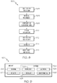
Fig. 7 is a flow diagram depicting an example of the disclosed method for damping a first member relative to a second member; -
Fig. 8 is a flow diagram of an aircraft manufacturing and service methodology; and -
Fig. 9 is a block diagram of an aircraft. - The following detailed description refers to the accompanying drawings, which illustrate specific examples described by the disclosure. Other examples having different structures and operations do not depart from the scope of the present disclosure. Like reference numerals may refer to the same feature, element, or component in the different drawings.
- Illustrative, non-exhaustive examples, which may be, but are not necessarily, claimed, of the subject matter according the present disclosure are provided below. Reference herein to "example" means that one or more feature, structure, element, component, characteristic and/or operational step described in connection with the example is included in at least one embodiment and/or implementation of the subject matter according to the present disclosure. Thus, the phrase "an example" and similar language throughout the present disclosure may, but do not necessarily, refer to the same example. Further, the subject matter characterizing any one example may, but does not necessarily, include the subject matter characterizing any other example.
- As used herein, the phrase "a number of' items means one or more of those items. For example, a number of items may include one item or a plurality of items. For the purpose of simplicity, throughout the present disclosure and unless otherwise indicated, use of the plural form of the referred to item means the number of items. For example, unless otherwise indicated, use of "items" means "the number of items."
- Referring to
Fig. 1 , the present disclosure provides examples of adamping system 200 for damping the movement of afirst member 10 relative to asecond member 20. Thedamping system 200 includes afirst member 10, asecond member 20, and adamping apparatus 100 for damping thefirst member 10 relative to thesecond member 20. Although thefirst member 10 and thesecond member 20 are shown as being a housing and a bolt, thefirst member 10 and thesecond member 20 may be any suitable combination of devices, structures, components and the like. Thedamping apparatus 100 may damp the intermobility of thefirst member 10 relative to thesecond member 20 such that significantly less mechanical energy is transferred between the two. In doing so, thedamping apparatus 100 significantly affixes their positions relative to one another. - The
first member 10 and thesecond member 20 may be made from various materials, such as aluminum, titanium and the like. Thefirst member 10 may be a monolithic structure or an assembly of smaller components. Similarly, thesecond member 20 may be a monolithic structure or assemblies of smaller components. - Referring to
Figs. 2-6 , disclosed is an example of adamping apparatus 100 for damping afirst member 10 relative to asecond member 20 ofdamping system 200. Here, thefirst member 10 includes afirst surface 11, asecond surface 12 opposed from thefirst surface 11, and a first member through-bore 13 (Fig. 5 ) extending between thefirst surface 11 and thesecond surface 12. Thedamping apparatus 100 includes a receivingmember 30, a first axialelastomeric member 60, a second axialelastomeric member 70 and a radialelastomeric member 80. The first axialelastomeric member 60 is positionable between thefirst surface 11 of thefirst member 10 and afirst flange 44 of the receivingmember 30. The second axialelastomeric member 70 is positionable between thesecond surface 12 of thefirst member 10 and asecond flange 54 of the receivingmember 30. The radialelastomeric member 80 is positionable within the first member through-bore 13 between thefirst member 10 and ashaft 32 of the receivingmember 30, as further explained below. - The receiving
member 30 includes ashaft 32 that extends through the first member through-bore 13. Theshaft 32 defines a shaft through-bore 34 extending along a shaft through-bore axis A. Theshaft 32 also includes afirst end portion 42, afirst flange 44 proximate thefirst end portion 42, asecond end portion 52 axially opposed from thefirst end portion 42, and asecond flange 54 proximate thesecond end portion 52. At least one of thefirst flange 44 and thesecond flange 54 may be connected to theshaft 32 by a suitable mechanism for connecting, such as adhesion, swaging, and the like. As shown, thefirst flange 44 and thesecond flange 54 are integral with theshaft 32 of the receivingmember 30. - The receiving
member 30 may at least partially receive thesecond member 20. By connecting thesecond member 20 to the receiving member 30 (such as by inserting the second member through the shaft through-bore of the receiving member), mechanical loads may be transferred between thesecond member 20 and the receivingmember 30. Those skilled in the art will appreciate however, that the efficiency of mechanical load transfer is related to the degree in which thesecond member 20 is in contact with the receivingmember 30. The tighter the connection between the receivingmember 30 and thesecond member 20, the more efficient the transfer of mechanical loads between the two may be. Further, a variety of other mechanisms (such as a ball joint type connection) may be employed to connect thesecond member 20 to the receivingmember 30 without departing from the scope of the present disclosure. - The receiving
member 30 may be made from any suitable material such as titanium, aluminum and the like. Further, the receivingmember 30 may be a single monolithic piece or an assembly of smaller components. In the example illustrated inFigs. 4-6 , the receivingmember 30 includes a first receivingmember portion 40 and a second receivingmember portion 50. The first receivingmember portion 40 includes afirst flange 44 and a portion of the receivingmember shaft 32. The secondreceiving member portion 50 includes asecond flange 54 and another portion of the receivingmember shaft 32. Those skilled in the art will appreciate that it may be easier to maneuver the receivingmember 30 in and out of the first member through-bore 13 if the receivingmember 30 was an assembly of several pieces, as opposed to being a single monolithic piece. - The first receiving
member portion 40 may be releasably connected to the second receivingmember portion 50. The mechanism by which the first and second receivingmember portions member portion 40 may includefirst threads 46 and the second receivingmember portion 50 may includesecond threads 56 that correspond to thefirst threads 46. In this example, the first receivingmember portion 40 may be in threaded engagement with the second receivingmember portion 50. In another example, the first receivingmember portion 40 may be adhered to the second receivingmember portion 50 in addition to being in threaded engagement. In yet another example, the first receivingmember portion 40 may be mechanically deformed (e.g., swaged) around the second receivingmember portion 50. Those skilled in the art will appreciate that other connection mechanisms or combinations of connection mechanisms may be employed without departing from the scope of the present disclosure. - Before the first receiving
member portion 40 and the second receivingmember portion 50 are releasably connected to one another, however, ashim 36 may be positioned between the first receivingmember portion 40 and the second receivingmember portion 50. More specifically, the first receivingmember portion 40 may include a firstinterior surface 48 and the second receivingmember portion 50 may include a secondinterior surface 58. When the first receivingmember portion 40 is threaded onto the second receivingmember portion 50, the first and second receivingmember portions gap 38 therebetween that corresponds to the space between the firstinterior surface 48 and the secondinterior surface 58. If used, ashim 36 may be positioned within thisgap 38 such that, even when threaded to the maximum extent possible, the first receivingmember portion 40 is spaced a predefined minimum distance D3 apart from the second receivingmember portion 50. - Those skilled in the art will appreciate that when a first axial
elastomeric member 60 and/or a secondaxial elastomeric 70 is positioned between their respective surfaces of thefirst member 10 and flanges of the receivingmember 30, that predefining a minimum distance D3 apart enables an operator to control the degree of clearance between those parts. Threading the first receivingmember 40 onto the second receivingmember portion 50 may, in an example, compress the first axialelastomeric member 60 between thefirst flange 44 and thefirst surface 11 of thefirst member 10, as well as the second axialelastomeric member 70 between thesecond flange 54 and thesecond surface 12 of thefirst member 10. Those skilled in the art will also appreciate that compressing an elastomeric material may alter the physical properties of that elastomeric material (such as by increasing stiffness). - Positioning a
shim 36 between the first and second receivingmember portions elastomeric member 60 and/or the second axialelastomeric member 70 are compressed. Positioning ashim 36 between the first and second receivingmember portions elastomeric members - The receiving
member 30 may also include torquing features. Those skilled in the art will appreciate that torquing features may be particularly useful in, but not limited to, examples of the dampingapparatus 100 that include a first receivingmember portion 40 in threaded engagement with a second receiving member portion 50 (such as the example illustrated inFigs 1-6 ) because the torquing features may facilitate the threading of the first receivingmember portion 40 onto the second receivingmember portion 50. - As shown, the
first flange 44 of the first receivingmember portion 40 includes afirst torquing feature 47 and thesecond flange 54 of the second receivingmember portion 50 includes asecond torquing feature 57. Thefirst torquing feature 47 may rotate the first receivingmember portion 40 about shaft through-bore axis A and thesecond torquing feature 57 may rotate the second receivingmember portion 50 about shaft through-bore axis A. The first and second torquing features 47, 57 include a plurality of divots that may correspond to an appropriate spanner wrench. Those skilled in the art will appreciate however, that any suitable mechanism for rotating the receiving member 30 (or any component thereof) may be employed without departing from the scope of the present disclosure. - The first axial
elastomeric member 60 is positionable between thefirst flange 44 and thefirst surface 11 of thefirst member 10. When positioned, thefirst flange 44 may provide a degree of protection to the first axialelastomeric member 60 from environmental factors such as radiation and oxygen exposure. Where relevant, thefirst flange 44 may also act as a seal in limiting or even preventing the first axialelastomeric member 60 from outgassing (e.g. releasing gas stored within). The degree to which thefirst flange 44 may protect and/or seal the first axialelastomeric member 60, however, is related to the size of the first axialelastomeric member 60 in relation to thefirst flange 44. - Referring to
Fig. 3 , at every angle about the shaft through-bore axis A, aperiphery 49 of thefirst flange 44 is located a first radial distance D1 from the shaft through-bore axis A and aperiphery 69 of the first axialelastomeric member 60 is located a second radial distance D2 from the shaft through-bore axis A. As shown, the first radial distance D1 is greater than the second radial distance D2. In one example, the second radial distance D2 may be at most about 95% of the first radial distance D1. In another example, the second radial distance D2 may be at most about 80% of the first radial distance D1. In yet another example, the second radial distance D2 may be at most about 65% of the first radial distance D1. Those skilled in the art will appreciate that thefirst flange 44 may provide greater protection to the first axialelastomeric member 60 in examples where the second radial distance D2 is less than the first radial distance D1, than in examples where the second radial distance D2 is greater than the first radial distance D1. - Those skilled in the art will also appreciate that the
second flange 54 may protect and/or seal the second axialelastomeric member 70 in the same way that thefirst flange 44 protects and/or seals the first axialelastomeric member 60. Similarly, thesecond flange 54 and the second axialelastomeric member 70 may also define peripheries (not shown) that are sized relative to one another in the same way as thefirst flange 44 and the first axialelastomeric member 60. - As best shown in
Fig. 5 , the first axialelastomeric member 60 and the second axialelastomeric member 70 may be generally planar and annular in shape. Those skilled in the art will appreciate, however, that nonplanar axial elastomeric members having non-annular shapes, such as a polygonal or irregular shapes, may be employed without departing from the scope of the present disclosure. In addition to shape, the first axialelastomeric member 60 and the secondaxial elastomeric 70 may also vary in size. More specifically (Fig. 4 ), the first axialelastomeric member 60 may have a thickness T1 measured parallel to the shaft through-bore axis A and the second axialelastomeric member 70 may have a thickness T2 measured parallel to the shaft through-bore axis A. In one example, T1 may be substantially equal in thickness to T2. In another example, T1 may be about twice as thick as T2. In yet another example, T1 may be about half as thick as T2. The thickness of T1 relative to T2 may be dictated primarily by end-use considerations and may vary widely without departing from the scope of the present disclosure. Further, the fact that the dampingapparatus 100 can accommodate such variability enables the dampingapparatus 100 to be more tailorable to any particular end-use application. - The radial
elastomeric member 80 is positionable between thefirst member 10 and the receivingmember 30. More specifically, thefirst member 10 and theshaft 32 of the receivingmember 30 may define anannular space 82 therebetween and the radialelastomeric member 80 may be sized and shaped to substantially fill thisannular space 82. Once positioned, the radialelastomeric member 80 may have a radial thickness T3 measured perpendicular to the shaft through-bore axis A. Those skilled in the art will appreciate that T3 may vary widely without departing from the scope of the present disclosure. - It is contemplated that additional axial and/or radial elastomeric members may be positioned proximate the first axial
elastomeric member 60, the secondelastomeric member 70 and the radialelastomeric member 80. Positioning multiple axial and/or radial elastomeric members may improve damping ability. In one example, two radial elastomeric members may be positioned within the first member through-bore 13 between thefirst member 10 and theshaft 32 of the receivingmember 30. In another example, three axial elastomeric members may be positioned between thefirst flange 44 of the receivingmember 30 and thefirst surface 11 of thefirst member 10. In yet another example, four axial elastomeric members may be positioned between thesecond flange 54 of the receivingmember 30 and thesecond surface 12 of thefirst member 10. Those skilled in the art will appreciate that any combination of quantity and axial and/or radial elastomeric member positions may be employed without departing from the scope of the present disclosure. - At this point, those skilled in the art will appreciate that the first axial
elastomeric member 60, the second axialelastomeric member 70 and the radial elastomeric member 80 (and any combination thereof) may independently or cooperatively damp thefirst member 10 relative to thesecond member 20. When a mechanical load is applied to either thefirst member 10 or the second member 20 (which transfers mechanical loads to and from the receiving member), thefirst member 10 and thesecond member 20 may move towards one another. When they do, at least one of the first axialelastomeric member 60, the second axialelastomeric member 70 and the radialelastomeric member 80 may compress in response (the first and second axialelastomeric members first member 10, and the radialelastomeric member 80 may compress between thefirst member 10 and theshaft 32 of the receiving member 30), which thereby lessens the transfer of mechanical energy between the first andsecond members - More specifically, the first and second axial
elastomeric members first member 10 relative to thesecond member 20, and the radialelastomeric member 80 may damp radial movement (e.g., perpendicular to shaft through-bore axis A) of thefirst member 10 relative to thesecond member 20. Further, at least one of the first axialelastomeric member 60 and the second axialelastomeric member 70 may cooperate with the radialelastomeric member 80 in damping diagonal movement of thefirst member 10 relative to thesecond member 20. - The first axial
elastomeric member 60, the second axialelastomeric member 70 and radialelastomeric member 80 may be made from any suitable elastomeric material and may be selected based on a variety of end-use considerations. For example, in applications taking place in space, it may be important to select elastomeric materials that exhibit high damping loss factor, compressive strength and stiffness, but low outgassing total mass loss. A suitable type of material for this application may include silicone-based elastomeric materials. It is generally contemplated, however, that the material compositions of the first axialelastomeric member 60, the second axialelastomeric member 70 and radialelastomeric member 80 may vary widely without departing from the scope of the present disclosure. - Different elastomeric materials may be used for each of the first axial
elastomeric member 60, the second axialelastomeric member 70 and the radialelastomeric member 80. Those skilled in the art will appreciate that the ability to select different elastomeric materials for each of the first axialelastomeric member 60, the second axialelastomeric member 70 and radialelastomeric member 80 enables the dampingapparatus 100 to be highly tailorable to any particular application. Further, the dampingapparatus 100 may be used in conjunction with a plurality of interchangeable elastomeric members (not shown). These interchangeable elastomeric members may be interchangeable with at least one of the first axialelastomeric member 60, the second axialelastomeric member 70 and the radialelastomeric member 80. - Each interchangeable elastomeric member of the plurality of interchangeable elastomeric members may also be compositionally distinct from at least one of the first axial
elastomeric member 60, the second axialelastomeric member 70 and the radialelastomeric member 80. Those skilled in the art will appreciate that the interchangeability of the first axialelastomeric member 60, the second axialelastomeric member 70 and the radialelastomeric member 80 further improves the tailorability of the dampingapparatus 100 because it allows the dampingapparatus 100 to be tailored after it has been in use. Tailoring the dampingapparatus 100 may be as simple as swapping out at least one of the first axialelastomeric member 60, the second axialelastomeric member 70 and radialelastomeric member 80 for an interchangeable elastomeric member. - As shown in
Fig. 7 , disclosed is an example of amethod 300 for damping afirst member 10 relative to asecond member 20. The size, shape and composition of thefirst member 10 and thesecond member 20 may vary. In one or more examples, however, thefirst member 10 may include afirst surface 11, asecond surface 12 opposed from thefirst surface 11, and a first member through-bore 13 extending between thefirst surface 11 and thesecond surface 12. - The
method 300 includes positioning a receivingmember 30 that includes a shaft through-bore 34 within the first member through-bore 13 (block 310). Thepositioning 310 may entail inserting the receivingmember 30 into the first member through-bore 13 or assembling thefirst member 10 around the receivingmember 30. This step may also vary depending on the type of receivingmember 30 used. In examples where the receivingmember 30 includes a first receivingmember portion 40 and a second receivingmember portion 50, the first and second receivingmember portions member shaft 32 into the first member through-bore 13. -
Example methods 300 that include using a receivingmember 30 that includes a first receivingmember portion 40 and a second receivingmember portion 50 may also include positioning ashim 36 between the first receivingmember portion 40 and the second receiving member portion 50 (block 320). In doing so, the first and second receivingmember portions shim 36. Theshim 36 prevents the first and second receivingmember portions elastomeric member 60 and the second axialelastomeric member 70 may be compressed between their respective surfaces of thefirst member 10 and a flanges of the receivingmember 30 while the dampingapparatus 100 is in use. - These examples may further include connecting the first receiving
member portion 40 and the second receiving member portion 50 (block 330). The first and second receivingmember portions - The
method 300 may also include selecting (block 340) a composition of elastomeric material, such as the composition of the axialelastomeric member 60 and/or the composition of the radialelastomeric member 80. The selecting 340 may be based on end-use considerations such as at least one of an optimal damping loss factor, an optimal degree of outgassing, and optimal compression strength and an optimal stiffness required for a particular application. Those skilled in the art will appreciate that other considerations may be considered in selecting a composition of elastomeric material without departing from the scope of the present disclosure. - The
method 300 further includes positioning at least one of an axialelastomeric member 60 and a radialelastomeric member 80 between the receivingmember 30 and the first member 10 (block 350). The axial elastomeric member may be positioned between aflange 44 of the receivingmember 30 and asurface 11 of thefirst member 10. The radial elastomeric member may be positioned within the first member through-bore 13 between thefirst member 10 and theshaft 32 of the receivingmember 30. Thepositioning 350 may also, however, include positioning multiple axial elastomeric members and/or multiple radial elastomeric members in those respective locations. - In one example, the positioning 310 of the receiving member may include positioning a receiving
member 30 that includes afirst flange 44, and thepositioning 350 of the at least one elastomeric member may include positioning the elastomeric member between thefirst surface 11 of thefirst member 10 and thefirst flange 44 of the receivingmember 30. In another example, the positioning 310 of the receiving member includes positioning a receivingmember 30 that includes asecond flange 54 and thepositioning 350 of the at least one elastomeric member includes positioning an elastomeric member between thesecond surface 12 of thefirst member 10 and thesecond flange 54 of the receivingmember 30. - The
method 300 also includes positioning thesecond member 20 within the shaft through-bore 34 (block 360). Thesecond member 20, as positioned, may extend entirely through the shaft through-bore 34 or partially through it. As shown, thisstep 360 may be as simple as inserting a bolt through the shaft through-bore 34 but, alternatively, it may also include the additional step of directly connecting thesecond member 20 to the receivingmember 30, such as by threaded means or an adhesive. - The
method 300 may include swapping at least one of the axialelastomeric member 60 and the radialelastomeric member 80 for an interchangeable elastomeric member (block 370). The interchangeable elastomeric member may be any axial or radialelastomeric member apparatus 100 to a particular application. - Examples of the disclosure may be described in the context of an aircraft manufacturing and
service method 500, as shown inFig. 8 , and anaircraft 502, as shown inFig. 9 . During pre-production, the aircraft manufacturing andservice method 500 may include specification anddesign 504 of theaircraft 502 andmaterial procurement 506. During production, component/subassembly manufacturing 508 andsystem integration 510 of theaircraft 502 takes place. Thereafter, theaircraft 502 may go through certification anddelivery 512 in order to be placed inservice 514. While in service by a customer, theaircraft 502 is scheduled for routine maintenance andservice 516, which may also include modification, reconfiguration, refurbishment and the like. - Each of the processes of
method 500 may be performed or carried out by a system integrator, a third party, and/or an operator (e.g., a customer). For the purposes of this description, a system integrator may include without limitation any number of aircraft manufacturers and major-system subcontractors; a third party may include without limitation any number of venders, subcontractors, and suppliers; and an operator may be an airline, leasing company, military entity, service organization, and so on. - As shown in
Fig. 9 , theaircraft 502 produced byexample method 500 may include anairframe 518 with a plurality ofsystems 520 and an interior 522. Examples of the plurality ofsystems 520 may include one or more of a propulsion system 524, anelectrical system 526, ahydraulic system 528, and anenvironmental system 530. Any number of other systems may be included. - The disclosed apparatus, system and method for damping a first member relative to a second member may be employed during any one or more of the stages of the aircraft manufacturing and
service method 500. As one example, the disclosed apparatus, system and method for damping a first member relative to a second member may be employed duringmaterial procurement 506. As another example, components or subassemblies corresponding to component/subassembly manufacturing 508,system integration 510, and or maintenance andservice 516 may be fabricated or manufactured using the disclosed apparatus, system and method for damping a first member relative to a second member. As another example, theairframe 518 and the interior 522 may be constructed using the disclosed apparatus, system and method for damping a first member relative to a second member. Also, one or more apparatus examples, method examples, or a combination thereof may be utilized during component/subassembly manufacturing 508 and/orsystem integration 510, for example, by substantially expediting assembly of or reducing the cost of anaircraft 502, such as theairframe 518 and/or the interior 522. Similarly, one or more of system examples, method examples, or a combination thereof may be utilized while theaircraft 502 is in service, for example and without limitation, to maintenance andservice 516. - The disclosed apparatus, system and method for damping a first member relative to a second member are described in the context of an aircraft; however, one of ordinary skill in the art will readily recognize that the disclosed apparatus, system and method for damping a first member relative to a second member may be utilized for a variety of applications. For example, the disclosed apparatus, system, and method for damping a first member relative to a second member may be implemented in various types of vehicles including, e.g., helicopters, passenger ships, automobiles, and the like.
- Further, the disclosure includes examples according to the following Clauses:
- Clause 1. A damping apparatus for damping a first member relative to a second member, said damping apparatus comprising: a receiving member comprising a flange; an axial elastomeric member positionable between a surface of said first member and said flange of said receiving member; and a radial elastomeric member positionable between said first member and said receiving member.
- Clause 2. The damping apparatus of Clause 1 further comprising a second axial elastomeric member positionable between a second surface of said first member and a second flange of said receiving member.
- Clause 3. The damping apparatus of Clause 1 or 2 wherein said receiving member further comprises a shaft that defines a shaft through-bore extending along a shaft through-bore axis.
- Clause 4. The damping apparatus of Clause 3 wherein, at each angle about said shaft through-bore axis: a periphery of said flange is located a first radial distance from said shaft through-bore axis; preferably a periphery of said axial elastomeric member is located a second radial distance from said shaft through-bore axis; and preferably said first radial distance is greater than said second radial distance.
- Clause 5. The damping apparatus of any one of Clauses 1 to 4 wherein said receiving member comprises a first receiving member portion and a second receiving member portion releasably connected to said first receiving member portion.
- Clause 6. The damping apparatus of any one of Clauses 1 to 5 wherein at least one of said axial elastomeric member and said radial elastomeric member comprises silicone.
- Clause 7. A damping apparatus for damping a first member relative to a second member, said first member comprising a first surface, a second surface opposed from said first surface, and a first member through-bore extending between said first surface and said second surface, said damping apparatus comprising: a receiving member comprising a shaft configured to extend through said first member through-bore, said shaft defining a shaft through-bore extending along a shaft through-bore axis, said shaft comprising a first end portion and a second end portion opposed from said first end portion, said receiving member further comprising a first flange proximate said first end portion of said shaft and a second flange proximate said second end portion of said shaft; a first axial elastomeric member positionable between said first surface of said first member and said first flange of said receiving member; a second axial elastomeric member positionable between said second surface of said first member and said second flange of said receiving member; and a radial elastomeric member positionable within said first member through-bore between said first member and said shaft of said receiving member.
- Clause 8. The damping apparatus of Clause 7 wherein each of said first axial elastomeric member and said second axial elastomeric member has an annular shape.
- Clause 9. The damping apparatus of Clause 7 or 8 wherein an annular space is defined between said first member and said shaft of said receiving member.
-
Clause 10. The damping apparatus of Clause 9 wherein said radial elastomeric member is sized and shaped to substantially fill said annular space. -
Clause 11. The damping apparatus of any one of Clauses 7 to 10 wherein at least one of said first axial elastomeric member, said second axial elastomeric member and said radial elastomeric member comprises silicone. -
Clause 12. The damping apparatus of any one of Clauses 7 to 11 wherein at least one of said first flange and said second flange is integral with said shaft of said receiving member. -
Clause 13. The damping apparatus of any one of Clauses 7 to 12 wherein, at each angle about said shaft through-bore axis: a periphery of said first flange is located a first radial distance from said shaft through-bore axis. - Clause 14. The damping apparatus of any one of Clauses 7 to 13 wherein, at each angle about said shaft through-bore axis: a periphery of said first axial elastomeric member is located a second radial distance from said shaft through-bore axis
- Clause 15. The damping apparatus of any one of Clauses 7 to 14 wherein, at each angle about said shaft through-bore axis: said first radial distance is greater than said second radial distance.
- Clause 16. The damping apparatus of any one of Clauses 7 to 12 wherein, at each angle about said shaft through-bore axis: a periphery of said first flange is located a first radial distance from said shaft through-bore axis.
- Clause 17. The damping apparatus of any one of Clauses 7 to 12 or 16 wherein, at each angle about said shaft through-bore axis: a periphery of said first axial elastomeric member is located a second radial distance from said shaft through-bore axis.
- Clause 18. The damping apparatus of any one of Clauses 7 to 12, 16, or 17 wherein, at each angle about said shaft through-bore axis: said second radial distance is at most about 95% of said first radial distance.
- Clause 19. The damping apparatus of any one of Clauses 7 to 18 wherein said receiving member comprises aluminum.
-
Clause 20. The damping apparatus of any one of Clauses 7 to 19 wherein said receiving member comprises a first receiving member portion and a second receiving member portion releasably connected to said first receiving member portion. - Clause 21. The damping apparatus of
Clause 20 wherein said first receiving member portion is in threaded engagement with said second receiving member portion. - Clause 22. The damping apparatus of
Clause 20 or 21 wherein said first receiving member portion and said second receiving member portion define a gap therebetween, and further comprising a shim at least partially received in said gap. - Clause 23. The damping apparatus of any one of
Clauses 20 to 22 wherein said first receiving member portion comprises a first torquing feature for rotating said first receiving member portion about said shaft through-bore axis. - Clause 24. The damping apparatus of Clause 23 wherein said second receiving member portion comprises a second torquing feature for rotating said second receiving member portion about said shaft through-bore axis.
- Clause 25. A damping system comprising: a first member comprising a first surface, a second surface opposed from said first surface, and a first member through-bore extending between said first surface and said second surface; the damping apparatus of any one of Clauses 7 to 24; and a second member at least partially received within said shaft through-bore of said receiving member.
- Clause 26. A damping system comprising: a first member comprising a first surface, a second surface opposed from said first surface, and a first member through-bore extending between said first surface and said second surface; a receiving member comprising a shaft extending through said first member through-bore, said shaft defining a shaft through-bore extending along a shaft through-bore axis, said shaft comprising a first end portion and a second end portion opposed from said first end portion, said receiving member further comprising a first flange connected to said first end portion of said shaft and a second flange connected to said second end portion of said shaft; a first axial elastomeric member positioned between said first surface of said first member and said first flange of said receiving member; a second axial elastomeric member positioned between said second surface of said first member and said second flange of said receiving member; a radial elastomeric member positioned within said first member through-bore between said first member and said shaft of said receiving member; and a second member at least partially received within said shaft through-bore of said receiving member.
- Clause 27. The damping system of Clause 25 or 26 wherein said first member comprises titanium.
- Clause 28. The damping system of any one of Clauses 25 to 27 further comprising a plurality of interchangeable elastomeric members,
- Clause 29. The damping system of Clause 28 wherein each interchangeable elastomeric member is interchangeable with at least one of said first axial elastomeric member,
-
Clause 30. The damping system of Clause 28 or 29 wherein said second axial elastomeric member and said radial elastomeric member. - Clause 31. The damping system of any one of Clauses 28 to 30 wherein each interchangeable elastomeric member of said plurality of interchangeable elastomeric members is compositionally distinct from at least one of said first axial elastomeric member, said second axial elastomeric member, and said radial elastomeric member.
-
Clause 32. A method for damping a first member relative to a second member, said first member comprising a first surface, a second surface opposed from said first surface, and a first member through-bore extending between said first surface and said second surface, said method comprising: positioning a receiving member comprising a shaft through-bore within said first member through-bore, positioning at least one of an axial elastomeric member or a radial elastomeric member between said receiving member and said first member, and positioning said second member within said shaft through-bore. - Clause 33. The method of
Clause 32 further comprising selecting a composition of said axial elastomeric member or said radial elastomeric member based on at least one of an optimal damping loss factor, an optimal degree of outgassing, an optimal compression strength, and an optimal stiffness required for a particular application. -
Clause 34. The method ofClause 32 or 33 wherein said positioning of said receiving member within said first member through-bore comprises positioning the receiving member that comprises a first receiving member portion and a second receiving member portion, - Clause 35. The method of
Clause 34 further comprising connecting said first receiving member portion to said second receiving member portion to form said receiving member. -
Clause 36. The method ofClause 34 or 35 further comprising positioning a shim between said first receiving member portion and said second receiving member portion such that said first receiving member portion and said second receiving member portion are spaced a predefined minimum distance apart. - Clause 37. The method of any one of
Clauses 32 to 36 wherein: said positioning of said receiving member comprises positioning the receiving member that comprises a first flange. -
Clause 38. The method of Clause 37 wherein said positioning of said at least one of said axial elastomeric member or said radial elastomeric member comprises positioning said at least one of said axial elastomeric member and said radial elastomeric member between said first surface of said first member and said first flange. - Clause 39. The method of
Clause 37 or 38 wherein: said positioning of said receiving member comprises positioning the receiving member that comprises a second flange. -
Clause 40. The method of Clause 39 wherein said positioning of said at least one of said axial elastomeric member or said radial elastomeric member comprises positioning said at least one of said axial elastomeric member and said radial elastomeric member between said second surface of said first member and said second flange. - Clause 41. The method of any one of
Clauses 32 to 40 further comprising swapping at least one of said axial elastomeric member and said radial elastomeric member for an interchangeable elastomeric member. - Although various examples of the disclosed apparatus, system and method for damping a first member relative to a second member have been shown and described, modifications may occur to those skilled in the art upon reading the specification. The present application includes such modifications and is limited only by the scope of the claims.
Claims (15)
- A damping apparatus (100) for damping a first member (10) relative to a second member (20), said damping apparatus (100) comprising:a receiving member (30) comprising a flange (44);an axial elastomeric member (60) configured to be positioned between a surface (11) of said first member (10) and said flange (44) of said receiving member (30); anda radial elastomeric member (80) configured to be positioned between said first member (10) and said receiving member (30).
- The damping apparatus (100) of Claim 1, further comprising a second axial elastomeric member (70) configured to be positioned between a second surface (12) of said first member (10) and a second flange (54) of said receiving member (30).
- The damping apparatus (100) of Claim 1 or 2, wherein said receiving member (30) further comprises a shaft (32) that defines a shaft through-bore (34) extending along a shaft through-bore axis (A).
- The damping apparatus (100) of Claim 3, wherein, at each angle about said shaft through-bore axis (A):a periphery (49) of said flange (44) is located a first radial distance (Di) from said shaft through-bore axis (A);a periphery (69) of said axial elastomeric member (60, 70) is located a second radial distance (D2) from said shaft through-bore axis (A); andsaid first radial distance (Di) is greater than said second radial distance (D2),preferably wherein said second radial distance (D2) is at most about 95% of said first radial distance (Di).
- The damping apparatus (100) of any one of Claims 1 to 4, wherein said receiving member (30) comprises a first receiving member portion (40) and a second receiving member portion (50) releasably connected to said first receiving member portion (40).
- The damping apparatus (100) of Claim 1, 4, or 5, further comprising a first member (10) having a first surface (11), a second surface (12) opposed from said first surface (11), and a first member through-bore (13) extending between said first surface (11) and said second surface (12), wherein said first member (10) is to be damped relative to a second member (20), and wherein:the receiving member (30) comprises a shaft (32) configured to extend through said first member through-bore (13), said shaft (32) defining a shaft through-bore (34) extending along a shaft through-bore axis (A), said shaft (32) comprising a first end portion (42) and a second end portion (52) opposed from said first end portion (42), said flange being a first flange (44) proximate said first end portion (42) of said shaft (32) and a second flange (54) proximate said second end portion (52) of said shaft (32);the axial elastomeric member being a first axial elastomeric member (60) configured to be positioned between said first surface (11) of said first member (10) and said first flange (44) of said receiving member (30); andthe radial elastomeric member (80) is configured to be positioned within said first member through-bore (13) between said first member (10) and said shaft (32) of said receiving member (30),the damping apparatus further comprising a second axial elastomeric member (70) configured to be positioned between said second surface (12) of said first member (10) and said second flange (54) of said receiving member (30).
- The damping apparatus (100) of Claim 6, wherein an annular space (82) is defined between said first member (10) and said shaft (32) of said receiving member (30), and wherein said radial elastomeric member (80) is sized and shaped to substantially fill said annular space (82).
- The damping apparatus (100) of Claim 6 or 7, wherein a first receiving member portion (40) and a second receiving member portion (50) of said receiving member (30) define a gap (38) therebetween, and further comprising a shim (36) at least partially received in said gap (38).
- The damping apparatus (100) of any one of Claims 6 to 8, wherein a first receiving member portion (40) of said receiving member (30) comprises a first torquing feature (47) for rotating said first receiving member portion (40) about said shaft through-bore axis (A),
preferably wherein a second receiving member portion (50) of said receiving member (30) comprises a second torquing feature (57) for rotating said second receiving member portion (50) about said shaft through-bore axis (A). - A damping system (200), comprising:a first member (10) comprising a first surface (11), a second surface (12) opposed from said first surface (11), and a first member through-bore (13) extending between said first surface (11) and said second surface (12);the damping apparatus (100) of any one of Claims 1 to 9; anda second member (20) at least partially received within said shaft through-bore (34) of said receiving member (30).
- The damping system (200) of Claim 10, further comprising a plurality of interchangeable elastomeric members, wherein each interchangeable elastomeric member is configured to be interchangeable with at least one of said axial elastomeric member (60, 70) and said radial elastomeric member (80),
preferably wherein each interchangeable elastomeric member of said plurality of interchangeable elastomeric members is compositionally distinct from at least one of said axial elastomeric member (60, 70) and said radial elastomeric member (80). - A method (300) for damping a first member (10) relative to a second member (20), wherein said first member (10) comprises a first surface (11), a second surface (12) opposed from said first surface (11), and a first member through-bore (13) extending between said first surface (11) and said second surface (12), said method (300) comprising:positioning (320) a receiving member (30) comprising a shaft through-bore (34) within said first member through-bore (13),positioning (350) at least one of an axial elastomeric member (60, 70) or a radial elastomeric member (80) between said receiving member (30) and said first member (10), andpositioning (360) said second member (20) within said shaft through-bore (34).
- The method (300) of Claim 12, further comprising selecting (340) a composition of said axial elastomeric member (60, 70) or said radial elastomeric member (80) based on at least one of a predefined damping loss factor, degree of outgassing, compression strength and stiffness.
- The method (300) of Claim 12 or 13, wherein said positioning (320) of said receiving member (30) within said first member through-bore (13) comprises positioning the receiving member (30) that comprises a first receiving member portion (40) and a second receiving member portion (50), said method (300) further comprising connecting (330) said first receiving member portion (40) to said second receiving member portion (50) to form said receiving member (30),
preferably further comprising positioning (320) a shim (36) between said first receiving member portion (40) and said second receiving member portion (50) such that said first receiving member portion (40) and said second receiving member portion (50) are spaced a predefined minimum distance (D3) apart. - The method (300) of any one of Claims 12 to 14, wherein:said positioning (320) of said receiving member (30) comprises positioning the receiving member (30) that comprises a first flange (54); andsaid positioning (350) of said at least one of said axial elastomeric member (60) or said radial elastomeric member (80) comprises positioning said at least one of said axial elastomeric member (60, 70) and said radial elastomeric member (80) between said first surface (11) of said first member (10) and said first flange (44).
Applications Claiming Priority (1)
| Application Number | Priority Date | Filing Date | Title |
|---|---|---|---|
| US16/520,586 US11274722B2 (en) | 2019-07-24 | 2019-07-24 | Damping apparatus and associated systems and methods for damping a first member relative to a second member |
Publications (1)
| Publication Number | Publication Date |
|---|---|
| EP3770459A1 true EP3770459A1 (en) | 2021-01-27 |
Family
ID=71092431
Family Applications (1)
| Application Number | Title | Priority Date | Filing Date |
|---|---|---|---|
| EP20179520.0A Pending EP3770459A1 (en) | 2019-07-24 | 2020-06-11 | Damping apparatus and associated systems and methods for damping a first member relative to a second member |
Country Status (4)
| Country | Link |
|---|---|
| US (1) | US11274722B2 (en) |
| EP (1) | EP3770459A1 (en) |
| JP (1) | JP7621745B2 (en) |
| CN (1) | CN112283290B (en) |
Families Citing this family (1)
| Publication number | Priority date | Publication date | Assignee | Title |
|---|---|---|---|---|
| US11888222B1 (en) | 2022-09-23 | 2024-01-30 | The Boeing Company | Flange for 3D printed antennas and related methods |
Citations (3)
| Publication number | Priority date | Publication date | Assignee | Title |
|---|---|---|---|---|
| US4213718A (en) * | 1979-06-22 | 1980-07-22 | Trw Inc. | Strut rod mounting assembly |
| WO1997012160A1 (en) * | 1995-09-26 | 1997-04-03 | Lord Corporation | Vibration isolation system including a passive tuned vibration absorber |
| EP2180203A2 (en) * | 2008-10-23 | 2010-04-28 | Honeywell International Inc. | Vibration isolators |
Family Cites Families (23)
| Publication number | Priority date | Publication date | Assignee | Title |
|---|---|---|---|---|
| US5286014A (en) * | 1993-02-12 | 1994-02-15 | Gencorp Inc. | Slipper bushing with improved axial load capacity |
| EP1467121A2 (en) | 2003-03-31 | 2004-10-13 | Com Dev Ltd. | Shock attenuating mounting bracket |
| US20050040576A1 (en) | 2003-08-20 | 2005-02-24 | Ernest Oxenknecht | Multi-axis isolator and assembly for the same |
| DE102004041426A1 (en) * | 2004-08-27 | 2006-03-30 | Daimlerchrysler Ag | elastomeric bearings |
| DE102004051566B4 (en) * | 2004-10-22 | 2008-06-12 | SGF SüDDEUTSCHE GELENKSCHEIBENFABRIK GMBH & CO. KG | Resilient socket arrangement |
| EP1817508B1 (en) * | 2004-11-29 | 2010-02-24 | Lord Corporation | Vehicle cab suspension damping bushing and method of making |
| JP2006194378A (en) | 2005-01-14 | 2006-07-27 | Tamagawa Seiki Co Ltd | Anti-vibration mounting structure for space stabilizer |
| JP2008202722A (en) * | 2007-02-21 | 2008-09-04 | Toyota Motor Corp | Stopper structure and anti-vibration structure for vehicle |
| JP5051702B2 (en) | 2007-07-02 | 2012-10-17 | Udトラックス株式会社 | Cab mount structure |
| JP5577208B2 (en) * | 2010-09-28 | 2014-08-20 | 東海ゴム工業株式会社 | Anti-vibration bush |
| CN102478095A (en) * | 2010-11-23 | 2012-05-30 | 大连创达技术交易市场有限公司 | Hydraulic damping rubber sleeve bearing capable of being automatically arranged |
| CN202158132U (en) * | 2011-07-18 | 2012-03-07 | 张传文 | Improved structure of shock absorber |
| JP2014224557A (en) * | 2013-05-15 | 2014-12-04 | 株式会社ブリヂストン | Anti-vibration device |
| CN105736685A (en) * | 2016-04-14 | 2016-07-06 | 中国第一汽车股份有限公司 | Vibration damping linkage mechanism for variable-speed control mechanism |
| KR101823968B1 (en) * | 2016-06-16 | 2018-01-31 | 아이아(주) | Roll-rod for vehicle |
| CN107816502A (en) * | 2016-09-14 | 2018-03-20 | 上汽通用五菱汽车股份有限公司 | A kind of subframe bush assembly |
| JP6921659B2 (en) | 2017-07-05 | 2021-08-18 | 株式会社ミツバ | Wiper device and its manufacturing method |
| DE102017122236A1 (en) * | 2017-09-26 | 2019-03-28 | Illinois Tool Works Inc. | Fixing system for fastening a component to a carrier component |
| US10422372B2 (en) * | 2017-10-27 | 2019-09-24 | Mf Ip Holding, Llc | Rotatable bushing |
| CN208268287U (en) * | 2018-04-27 | 2018-12-21 | 中国科学院西安光学精密机械研究所 | Rubber shock absorber |
| CN109083956B (en) * | 2018-10-08 | 2021-01-22 | 株洲时代瑞唯减振装备有限公司 | Method for improving axial rigidity and reducing radial and deflection rigidity of elastic composite element |
| RU186496U1 (en) * | 2018-10-11 | 2019-01-22 | Федеральное государственное бюджетное образовательное учреждение высшего образования "Санкт-Петербургский государственный архитектурно-строительный университет" | VIBRATION PROTECTION HINGE |
| CN109667866A (en) * | 2019-02-01 | 2019-04-23 | 泉州市欣龙汽车零部件制造有限公司 | Connector and bearing pin assembly |
-
2019
- 2019-07-24 US US16/520,586 patent/US11274722B2/en active Active
-
2020
- 2020-06-03 JP JP2020096853A patent/JP7621745B2/en active Active
- 2020-06-11 EP EP20179520.0A patent/EP3770459A1/en active Pending
- 2020-07-14 CN CN202010673438.1A patent/CN112283290B/en active Active
Patent Citations (3)
| Publication number | Priority date | Publication date | Assignee | Title |
|---|---|---|---|---|
| US4213718A (en) * | 1979-06-22 | 1980-07-22 | Trw Inc. | Strut rod mounting assembly |
| WO1997012160A1 (en) * | 1995-09-26 | 1997-04-03 | Lord Corporation | Vibration isolation system including a passive tuned vibration absorber |
| EP2180203A2 (en) * | 2008-10-23 | 2010-04-28 | Honeywell International Inc. | Vibration isolators |
Also Published As
| Publication number | Publication date |
|---|---|
| CN112283290A (en) | 2021-01-29 |
| CN112283290B (en) | 2025-02-25 |
| JP7621745B2 (en) | 2025-01-27 |
| JP2021021482A (en) | 2021-02-18 |
| US20210025468A1 (en) | 2021-01-28 |
| US11274722B2 (en) | 2022-03-15 |
Similar Documents
| Publication | Publication Date | Title |
|---|---|---|
| US5592814A (en) | Attaching brittle composite structures in gas turbine engines for resiliently accommodating thermal expansion | |
| EP2589834B1 (en) | Mounting systems for structural members, fastening assemblies thereof, and vibration isolation systems including the same | |
| US6199801B1 (en) | Whole-spacecraft passive isolation devices | |
| US11725774B2 (en) | Isolation coupler for a structural assembly and method for attenuating a load | |
| CN104334914B (en) | Damping mechanical linkage which controls | |
| US10479471B2 (en) | Fuselage skin panel connection system and method for connecting skin panels | |
| EP3770459A1 (en) | Damping apparatus and associated systems and methods for damping a first member relative to a second member | |
| US11719007B2 (en) | Turnbuckle-style support strut with tunable stiffness | |
| US10690159B2 (en) | Fastening system with a washer having an enlarged bore facing a composite panel | |
| EP3392520A1 (en) | Vibration damping link and method therefore | |
| US11767770B2 (en) | Double bipod fitting to mitigate thermal loading of engine exhaust structures | |
| JP2022125994A (en) | Composite tanks for reusable launch vehicles and methods of fabricating the same | |
| US20260071593A1 (en) | Joint for mounting components on a rocket | |
| US20260071592A1 (en) | Joint for mounting components on a rocket | |
| Sanford | Development and Structural Qualification of the EELV Secondary Payload Adapter (ESPA) | |
| US12083674B2 (en) | Preloaded strut | |
| Holemans | Lessons Learned Developing Separation Systems For Small Satellites | |
| US6793479B1 (en) | Remotely actuated localized pressure and heat apparatus and method of use | |
| Higgins et al. | Testing of a Delta IV Payload Attach Fitting (PAF) Substructure with an Integral Composite Flange | |
| Romberg | Passive damping device for sandwich structures | |
| Palmieri et al. | Development And Qualification Of The Primary Structure Of The Orion European Service Module | |
| CN117759679A (en) | A vibration isolation and noise reduction system for manned spacecraft control moment gyro | |
| Cavallaro et al. | Testing and Analysis of Modified HMMWV Front Lift Provisions | |
| Hissam et al. | Analysis of a Preloaded Bolted Joint in a Ceramic Composite Combustor | |
| Ritchie | Design Trade-Offs that Determine Fastener Selection |
Legal Events
| Date | Code | Title | Description |
|---|---|---|---|
| PUAI | Public reference made under article 153(3) epc to a published international application that has entered the european phase |
Free format text: ORIGINAL CODE: 0009012 |
|
| STAA | Information on the status of an ep patent application or granted ep patent |
Free format text: STATUS: THE APPLICATION HAS BEEN PUBLISHED |
|
| AK | Designated contracting states |
Kind code of ref document: A1 Designated state(s): AL AT BE BG CH CY CZ DE DK EE ES FI FR GB GR HR HU IE IS IT LI LT LU LV MC MK MT NL NO PL PT RO RS SE SI SK SM TR |
|
| AX | Request for extension of the european patent |
Extension state: BA ME |
|
| STAA | Information on the status of an ep patent application or granted ep patent |
Free format text: STATUS: REQUEST FOR EXAMINATION WAS MADE |
|
| 17P | Request for examination filed |
Effective date: 20210726 |
|
| RBV | Designated contracting states (corrected) |
Designated state(s): AL AT BE BG CH CY CZ DE DK EE ES FI FR GB GR HR HU IE IS IT LI LT LU LV MC MK MT NL NO PL PT RO RS SE SI SK SM TR |
|
| RAP3 | Party data changed (applicant data changed or rights of an application transferred) |
Owner name: THE BOEING COMPANY |
|
| STAA | Information on the status of an ep patent application or granted ep patent |
Free format text: STATUS: EXAMINATION IS IN PROGRESS |
|
| 17Q | First examination report despatched |
Effective date: 20240403 |