EP3770400A1 - Low power hybrid turbofan drag reduction - Google Patents
Low power hybrid turbofan drag reduction Download PDFInfo
- Publication number
- EP3770400A1 EP3770400A1 EP20187522.6A EP20187522A EP3770400A1 EP 3770400 A1 EP3770400 A1 EP 3770400A1 EP 20187522 A EP20187522 A EP 20187522A EP 3770400 A1 EP3770400 A1 EP 3770400A1
- Authority
- EP
- European Patent Office
- Prior art keywords
- fan
- electric motor
- nacelle
- drag
- engine
- Prior art date
- Legal status (The legal status is an assumption and is not a legal conclusion. Google has not performed a legal analysis and makes no representation as to the accuracy of the status listed.)
- Withdrawn
Links
- 230000009467 reduction Effects 0.000 title description 4
- 238000000034 method Methods 0.000 claims abstract description 11
- 230000008878 coupling Effects 0.000 claims abstract description 6
- 238000010168 coupling process Methods 0.000 claims abstract description 6
- 238000005859 coupling reaction Methods 0.000 claims abstract description 6
- 238000004146 energy storage Methods 0.000 claims description 6
- 230000004044 response Effects 0.000 claims description 6
- 230000002829 reductive effect Effects 0.000 claims description 4
- 238000004891 communication Methods 0.000 claims description 3
- 230000001141 propulsive effect Effects 0.000 description 7
- 239000000446 fuel Substances 0.000 description 6
- 230000000670 limiting effect Effects 0.000 description 6
- 238000000926 separation method Methods 0.000 description 4
- 230000004048 modification Effects 0.000 description 3
- 238000012986 modification Methods 0.000 description 3
- 238000001514 detection method Methods 0.000 description 2
- 230000003068 static effect Effects 0.000 description 2
- 230000002411 adverse Effects 0.000 description 1
- 230000000903 blocking effect Effects 0.000 description 1
- 230000008859 change Effects 0.000 description 1
- 238000002485 combustion reaction Methods 0.000 description 1
- 230000006835 compression Effects 0.000 description 1
- 238000007906 compression Methods 0.000 description 1
- 238000012937 correction Methods 0.000 description 1
- 230000003247 decreasing effect Effects 0.000 description 1
- 238000013461 design Methods 0.000 description 1
- 230000003116 impacting effect Effects 0.000 description 1
- 230000007246 mechanism Effects 0.000 description 1
- 230000036961 partial effect Effects 0.000 description 1
- 230000008569 process Effects 0.000 description 1
- 230000035939 shock Effects 0.000 description 1
- 238000012546 transfer Methods 0.000 description 1
Images


Classifications
-
- F—MECHANICAL ENGINEERING; LIGHTING; HEATING; WEAPONS; BLASTING
- F02—COMBUSTION ENGINES; HOT-GAS OR COMBUSTION-PRODUCT ENGINE PLANTS
- F02C—GAS-TURBINE PLANTS; AIR INTAKES FOR JET-PROPULSION PLANTS; CONTROLLING FUEL SUPPLY IN AIR-BREATHING JET-PROPULSION PLANTS
- F02C7/00—Features, components parts, details or accessories, not provided for in, or of interest apart form groups F02C1/00 - F02C6/00; Air intakes for jet-propulsion plants
- F02C7/04—Air intakes for gas-turbine plants or jet-propulsion plants
-
- F—MECHANICAL ENGINEERING; LIGHTING; HEATING; WEAPONS; BLASTING
- F02—COMBUSTION ENGINES; HOT-GAS OR COMBUSTION-PRODUCT ENGINE PLANTS
- F02C—GAS-TURBINE PLANTS; AIR INTAKES FOR JET-PROPULSION PLANTS; CONTROLLING FUEL SUPPLY IN AIR-BREATHING JET-PROPULSION PLANTS
- F02C9/00—Controlling gas-turbine plants; Controlling fuel supply in air- breathing jet-propulsion plants
- F02C9/16—Control of working fluid flow
-
- B—PERFORMING OPERATIONS; TRANSPORTING
- B64—AIRCRAFT; AVIATION; COSMONAUTICS
- B64D—EQUIPMENT FOR FITTING IN OR TO AIRCRAFT; FLIGHT SUITS; PARACHUTES; ARRANGEMENT OR MOUNTING OF POWER PLANTS OR PROPULSION TRANSMISSIONS IN AIRCRAFT
- B64D33/00—Arrangement in aircraft of power plant parts or auxiliaries not otherwise provided for
- B64D33/02—Arrangement in aircraft of power plant parts or auxiliaries not otherwise provided for of combustion air intakes
-
- F—MECHANICAL ENGINEERING; LIGHTING; HEATING; WEAPONS; BLASTING
- F02—COMBUSTION ENGINES; HOT-GAS OR COMBUSTION-PRODUCT ENGINE PLANTS
- F02C—GAS-TURBINE PLANTS; AIR INTAKES FOR JET-PROPULSION PLANTS; CONTROLLING FUEL SUPPLY IN AIR-BREATHING JET-PROPULSION PLANTS
- F02C7/00—Features, components parts, details or accessories, not provided for in, or of interest apart form groups F02C1/00 - F02C6/00; Air intakes for jet-propulsion plants
- F02C7/04—Air intakes for gas-turbine plants or jet-propulsion plants
- F02C7/057—Control or regulation
-
- F—MECHANICAL ENGINEERING; LIGHTING; HEATING; WEAPONS; BLASTING
- F02—COMBUSTION ENGINES; HOT-GAS OR COMBUSTION-PRODUCT ENGINE PLANTS
- F02K—JET-PROPULSION PLANTS
- F02K3/00—Plants including a gas turbine driving a compressor or a ducted fan
- F02K3/02—Plants including a gas turbine driving a compressor or a ducted fan in which part of the working fluid by-passes the turbine and combustion chamber
- F02K3/04—Plants including a gas turbine driving a compressor or a ducted fan in which part of the working fluid by-passes the turbine and combustion chamber the plant including ducted fans, i.e. fans with high volume, low pressure outputs, for augmenting the jet thrust, e.g. of double-flow type
- F02K3/06—Plants including a gas turbine driving a compressor or a ducted fan in which part of the working fluid by-passes the turbine and combustion chamber the plant including ducted fans, i.e. fans with high volume, low pressure outputs, for augmenting the jet thrust, e.g. of double-flow type with front fan
-
- F—MECHANICAL ENGINEERING; LIGHTING; HEATING; WEAPONS; BLASTING
- F02—COMBUSTION ENGINES; HOT-GAS OR COMBUSTION-PRODUCT ENGINE PLANTS
- F02K—JET-PROPULSION PLANTS
- F02K5/00—Plants including an engine, other than a gas turbine, driving a compressor or a ducted fan
-
- B—PERFORMING OPERATIONS; TRANSPORTING
- B64—AIRCRAFT; AVIATION; COSMONAUTICS
- B64D—EQUIPMENT FOR FITTING IN OR TO AIRCRAFT; FLIGHT SUITS; PARACHUTES; ARRANGEMENT OR MOUNTING OF POWER PLANTS OR PROPULSION TRANSMISSIONS IN AIRCRAFT
- B64D33/00—Arrangement in aircraft of power plant parts or auxiliaries not otherwise provided for
- B64D33/02—Arrangement in aircraft of power plant parts or auxiliaries not otherwise provided for of combustion air intakes
- B64D2033/0226—Arrangement in aircraft of power plant parts or auxiliaries not otherwise provided for of combustion air intakes comprising boundary layer control means
-
- F—MECHANICAL ENGINEERING; LIGHTING; HEATING; WEAPONS; BLASTING
- F05—INDEXING SCHEMES RELATING TO ENGINES OR PUMPS IN VARIOUS SUBCLASSES OF CLASSES F01-F04
- F05D—INDEXING SCHEME FOR ASPECTS RELATING TO NON-POSITIVE-DISPLACEMENT MACHINES OR ENGINES, GAS-TURBINES OR JET-PROPULSION PLANTS
- F05D2220/00—Application
- F05D2220/30—Application in turbines
- F05D2220/32—Application in turbines in gas turbines
- F05D2220/323—Application in turbines in gas turbines for aircraft propulsion, e.g. jet engines
-
- F—MECHANICAL ENGINEERING; LIGHTING; HEATING; WEAPONS; BLASTING
- F05—INDEXING SCHEMES RELATING TO ENGINES OR PUMPS IN VARIOUS SUBCLASSES OF CLASSES F01-F04
- F05D—INDEXING SCHEME FOR ASPECTS RELATING TO NON-POSITIVE-DISPLACEMENT MACHINES OR ENGINES, GAS-TURBINES OR JET-PROPULSION PLANTS
- F05D2220/00—Application
- F05D2220/30—Application in turbines
- F05D2220/36—Application in turbines specially adapted for the fan of turbofan engines
-
- F—MECHANICAL ENGINEERING; LIGHTING; HEATING; WEAPONS; BLASTING
- F05—INDEXING SCHEMES RELATING TO ENGINES OR PUMPS IN VARIOUS SUBCLASSES OF CLASSES F01-F04
- F05D—INDEXING SCHEME FOR ASPECTS RELATING TO NON-POSITIVE-DISPLACEMENT MACHINES OR ENGINES, GAS-TURBINES OR JET-PROPULSION PLANTS
- F05D2220/00—Application
- F05D2220/70—Application in combination with
- F05D2220/76—Application in combination with an electrical generator
-
- F—MECHANICAL ENGINEERING; LIGHTING; HEATING; WEAPONS; BLASTING
- F05—INDEXING SCHEMES RELATING TO ENGINES OR PUMPS IN VARIOUS SUBCLASSES OF CLASSES F01-F04
- F05D—INDEXING SCHEME FOR ASPECTS RELATING TO NON-POSITIVE-DISPLACEMENT MACHINES OR ENGINES, GAS-TURBINES OR JET-PROPULSION PLANTS
- F05D2260/00—Function
- F05D2260/70—Adjusting of angle of incidence or attack of rotating blades
-
- F—MECHANICAL ENGINEERING; LIGHTING; HEATING; WEAPONS; BLASTING
- F05—INDEXING SCHEMES RELATING TO ENGINES OR PUMPS IN VARIOUS SUBCLASSES OF CLASSES F01-F04
- F05D—INDEXING SCHEME FOR ASPECTS RELATING TO NON-POSITIVE-DISPLACEMENT MACHINES OR ENGINES, GAS-TURBINES OR JET-PROPULSION PLANTS
- F05D2270/00—Control
- F05D2270/01—Purpose of the control system
- F05D2270/07—Purpose of the control system to improve fuel economy
- F05D2270/071—Purpose of the control system to improve fuel economy in particular at idling speed
Definitions
- the in-flight operating condition includes one of a low engine power condition or an engine off condition.
- the nacelle 18 includes a leading edge 76 forward of the fan blades 22 and a plurality of exit guide vanes 62 (one shown in Figure 1 ) disposed about the axis A within the bypass passage 16.
- the leading edge 76 of the nacelle 18 and fan exit guide vanes 62 are configured to provide efficient airflow during engine operation where the fan 22 is rotating to provide a propulsive thrust. Airflow through the bypass duct 16 may be disrupted when the fan section 22 is not rotating under power from the engine 20.
- the fan section 22 may rotate in the non-powered condition in response to airflow through the fan blades 42 due to forward movement of the aircraft.
- the rotation of the fan section 22 in response to such an airflow is typically referred to as windmilling.
Landscapes
- Engineering & Computer Science (AREA)
- Chemical & Material Sciences (AREA)
- Combustion & Propulsion (AREA)
- Mechanical Engineering (AREA)
- General Engineering & Computer Science (AREA)
- Physics & Mathematics (AREA)
- Fluid Mechanics (AREA)
- Aviation & Aerospace Engineering (AREA)
- Structures Of Non-Positive Displacement Pumps (AREA)
- Retarders (AREA)
Abstract
Description
- A gas turbine engine typically includes a fan section, a compressor section, a combustor section and a turbine section. Air entering the compressor section is compressed and delivered into the combustion section where it is mixed with fuel and ignited to generate a high-energy exhaust gas flow. The high-energy exhaust gas flow expands through the turbine section to drive the compressor and the fan section. The compressor section typically includes low and high pressure compressors, and the turbine section includes low and high pressure turbines.
- The fan section may generate a drag on the aircraft during low or engine off conditions during flight. The increased drag created during low or engine off conditions may impact engine and aircraft performance efficiency.
- In accordance with a first aspect of the present disclosure, a method of operating a turbofan engine includes coupling an electric motor to drive a fan rotatable within a nacelle, detecting an in-flight operating condition indicative of an increase in drag, and driving rotation of the fan with the electric motor to redirect a flow of air through the nacelle to reduce drag.
- In an embodiment according to the previous embodiment, the in-flight operating condition includes one of a low engine power condition or an engine off condition.
- In another embodiment according to any of the previous embodiments, the nacelle includes a plurality of exit guide vanes aft of the fan and redirecting a flow air includes adjusting an incident angle of airflow relative to a fan rotational axis from the fan by rotating the fan with the electric motor.
- In another embodiment according to any of the previous embodiments, the incident angle of airflow is adjusted from a first angle corresponding with a non-powered fan to a second angle corresponding with a powered rotation of the fan.
- In another embodiment according to any of the previous embodiments, the first angle is less than the second angle.
- In another embodiment according to any of the previous embodiments, a portion of the increase in drag is generated by an airflow stagnation region at a leading edge of the nacelle being at a first location and driving rotation of the fan includes adjusting the airflow stagnation region at the leading edge toward a second location corresponding with a reduced drag condition.
- In another embodiment according to any of the previous embodiments, the first location is radially inboard of the second location at the leading edge of the nacelle.
- In another embodiment according to any of the previous embodiments, a controller receives information indicative of the in-flight operating condition and controls operation of the electric motor to drive the fan.
- In another embodiment according to any of the previous embodiments, an energy storage system is coupled to the electric motor and provides energy to the electric motor in response to detecting the in-flight operating condition indicative of an increase in drag.
- In another embodiment according to any of the previous embodiments, the turbofan engine includes a fan drive gear system coupled between a shaft driven by a turbine section and the electric motor is coupled to the shaft to drive the fan through the fan drive gear system.
- In another embodiment according to any of the previous embodiments, the turbine section and shaft include a portion of a low spool.
- In accordance with a second aspect of the present disclosure, a turbofan engine includes a fan rotatable about an axis within a nacelle. An electric motor is coupled to the fan. A controller is programmed to operate the electric motor to rotate the fan to redirect a flow of air through the nacelle to reduce drag during an in-flight operating condition indicative of an increase in drag.
- In an embodiment according to the previous embodiment, a plurality of exit guide vanes are within the nacelle aft of the fan and the controller is programmed to adjust an incident angle of airflow relative to a fan rotational axis from the fan by rotating the fan with the electric motor.
- In another embodiment according to any of the previous embodiments, the incident angle of airflow is adjusted from a first angle corresponding with a non-powered fan to a second angle corresponding with powered rotation of the fan. The first angle is less than the second angle.
- In another embodiment according to any of the previous embodiments, the controller is in communication with systems providing information indicative of engine operation for determining the in-flight operating condition indicative of an increase in drag.
- In another embodiment according to any of the previous embodiments, a portion of the increase in drag is generated by an airflow stagnation region at a leading edge of the nacelle being at a first location and the controller operates the electric motor to rotate the fan to adjust the airflow stagnation region at the leading edge toward a second location corresponding with a reduced drag condition, wherein the first location is radially inboard of the second location at the leading edge of the nacelle.
- In another embodiment according to any of the previous embodiments, an energy storage system is coupled to the electric motor and providing energy to the electric motor.
- In another embodiment according to any of the previous embodiments, a fan drive gear system is coupled to a shaft driven by a turbine section for driving the fan at a speed different than the turbine section. The electric motor is coupled to the shaft to drive the fan through the fan drive gear system.
- Although the different examples have the specific components shown in the illustrations, embodiments of this invention are not limited to those particular combinations. It is possible to use some of the components or features from one of the examples in combination with features or components from another one of the examples.
- These and other features disclosed herein can be best understood from the following specification and drawings, the following of which is a brief description.
-
-
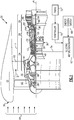
Figure 1 is a schematic view of an example turbofan engine. -
Figure 2 is a schematic view of an example orientation between fan blades and fan exit guide vanes within a bypass flow passage. -
Figure 3 is a schematic view of a front portion of an example turbofan engine embodiment. -
Figure 4 is a schematic view of a leading edge of an example nacelle. -
Figure 1 schematically illustrates aturbofan engine 20. Theturbofan engine 20 is disclosed herein as a two-spool turbofan that generally incorporates afan section 22 and acore engine section 14 including acompressor section 24, acombustor section 26 and aturbine section 28. Thefan section 22 drives bypass airflow B along abypass passage 16 defined within anacelle 18, and also drives air along a core flow path C for compression and communication into thecombustor section 26 followed by expansion through theturbine section 28. Although depicted as a two-spool turbofan gas turbine engine in the disclosed non-limiting embodiment, it should be understood that the concepts described herein are not limited to use with two-spool turbofans as the teachings may be applied to other types of turbine engines including three-spool architectures. - The
exemplary engine 20 generally includes alow speed spool 30 and ahigh speed spool 32 mounted for rotation about an engine central longitudinal axis A relative to an enginestatic structure 36 viaseveral bearing systems 38. It should be understood that thebearing systems 38 may be provided at different locations and that the location ofbearing systems 38 may be varied as appropriate to the application. - The
low speed spool 30 generally includes aninner shaft 40 that interconnects, a first (or low)pressure compressor 44 and a first (or low)pressure turbine 46. Theinner shaft 40 is connected to thefan section 22 through a speed change mechanism, which in theexemplary engine 20 is illustrated as a gearedarchitecture 48 to drivefan blades 42 at a lower speed than thelow speed spool 30. Thehigh speed spool 32 includes anouter shaft 50 that interconnects a second (or high)pressure compressor 52 and a second (or high)pressure turbine 54. Acombustor 56 is arranged in theexemplary turbofan engine 20 between thehigh pressure compressor 52 and thehigh pressure turbine 54. A mid-turbine frame 58 of the enginestatic structure 36 may be arranged generally between thehigh pressure turbine 54 and thelow pressure turbine 46. The mid-turbine frame 58 further supports bearingsystems 38 in theturbine section 28. Theinner shaft 40 and theouter shaft 50 are concentric and rotate via bearing thesystems 38 about the engine central longitudinal axis A which is collinear with their longitudinal axes. - The core airflow is compressed by the
low pressure compressor 44 then thehigh pressure compressor 52, mixed and burned with fuel in thecombustor 56, then expanded over thehigh pressure turbine 54 andlow pressure turbine 46. The mid-turbine frame 58 includesairfoils 60 which are in the core airflow path C. Theturbines low speed spool 30 andhigh speed spool 32 in response to the expansion. It will be appreciated that each of the positions of thefan section 22,compressor section 24,combustor section 26,turbine section 28, and fandrive gear system 48 may be varied. For example,gear system 48 may be located aft of thelow pressure compressor 44 and thefan blades 42 may be positioned forward or aft of the location of the gearedarchitecture 48 or even aft of theturbine section 28. - The
engine 20 in one example is a high-bypass geared aircraft engine. In a further example, theengine 20 bypass ratio is greater than about six, with an example embodiment being greater than about ten, the gearedarchitecture 48 is an epicyclic gear train, such as a planetary gear system or other gear system, with a gear reduction ratio of greater than about 2.3 and thelow pressure turbine 46 has a pressure ratio that is greater than about five. In one disclosed embodiment, the bypass ratio is greater than about ten, a fan diameter is significantly larger than that of thelow pressure compressor 44, and thelow pressure turbine 46 has a pressure ratio that is greater than about five. The pressure ratio of thelow pressure turbine 46 is the pressure measured prior to an inlet of thelow pressure turbine 46 as related to the pressure measured at the outlet of thelow pressure turbine 46 prior to an exhaust nozzle. The gearedarchitecture 48 may be an epicycle gear train, such as a planetary gear system or other gear system, with a gear reduction ratio of greater than about 2.3:1 and less than about 5:1. It should be understood, however, that the above parameters are only exemplary of one embodiment of a geared architecture turbofan engine and that the present invention is applicable to other gas turbine engines including direct drive turbofans. - A significant amount of thrust is provided by the bypass airflow B due to the high bypass ratio. The
fan section 22 of theengine 20 is designed for a particular flight condition -- typically cruise at about 0.8 Mach and about 35,000 feet (10,668 meters). The flight condition of 0.8 Mach and 35,000 ft (10,668 meters), with the engine at its best fuel consumption - also known as "bucket cruise Thrust Specific Fuel Consumption ('TSFC')" - is the industry standard parameter of lbm of fuel being burned divided by lbf of thrust the engine produces at that minimum point. "Low fan pressure ratio" is the pressure ratio across thefan blades 42 alone, without consideration of a Fan Exit Guide Vane ("FEGV") system. The low fan pressure ratio as disclosed herein according to one non-limiting embodiment is less than about 1.45. "Low corrected fan tip speed" is the actual fan tip speed in ft/sec divided by an industry standard temperature correction of [(Tram °R) / (518.7 °R)]0.5 (where °R = K x 9/5). The "Low corrected fan tip speed" as disclosed herein according to one non-limiting embodiment is less than about 1150 ft / second (350.5 meters/second). - The example gas turbine engine includes the
fan section 22 that comprises in one non-limiting embodiment less than about twenty-sixfan blades 42. In another non-limiting embodiment, thefan section 22 includes less than about twentyfan blades 42. Moreover, in one disclosed embodiment thelow pressure turbine 46 includes no more than about six turbine rotors schematically indicated at 34. In another non-limiting example embodiment, thelow pressure turbine 46 includes about three turbine rotors. A ratio between the number offan blades 42 and the number of low pressure turbine rotors is between about 3.3 and about 8.6. The examplelow pressure turbine 46 provides the driving power to rotate thefan section 22 and therefore the relationship between the number ofturbine rotors 34 in thelow pressure turbine 46 and the number ofblades 42 in thefan section 22 disclose an exampleturbofan turbine engine 20 with increased power transfer efficiency. - The
nacelle 18 includes aleading edge 76 forward of thefan blades 22 and a plurality of exit guide vanes 62 (one shown inFigure 1 ) disposed about the axis A within thebypass passage 16. The leadingedge 76 of thenacelle 18 and fanexit guide vanes 62 are configured to provide efficient airflow during engine operation where thefan 22 is rotating to provide a propulsive thrust. Airflow through thebypass duct 16 may be disrupted when thefan section 22 is not rotating under power from theengine 20. Thefan section 22 may rotate in the non-powered condition in response to airflow through thefan blades 42 due to forward movement of the aircraft. The rotation of thefan section 22 in response to such an airflow is typically referred to as windmilling. Thenacelle 18 is configured based at least in part on drag performance when thefan section 22 is windmilling. Thenacelle 18 is configured to prevent excessive drag during windmilling operation of a non-operating engine. The disrupted airflow within thebypass duct 16 generated during windmilling may cause partial blockage of airflow that disrupts incoming airflow schematically shown at 64 at theleading edge 76 of thenacelle 18. The disruption ofincoming airflow 64 may result in an increase in drag produced by the non-powered engine above predefined limits triggering modifications to thenacelle 18 to accommodate engine off conditions. Any modification to thenacelle 18 to address engine off operation may reduce operating efficiencies during normal engine operating conditions. - A disclosed engine embodiment includes an
electric motor 66 coupled to drive theinner shaft 40 during low or no power engine operating conditions to drive thefan section 22 to redirect a flow of air through thenacelle 18 to reduce drag produced by the non-powered engine during in-flight operating conditions. Rotation of the fan directs a flow of air through thenacelle 18 at an incident angle that is moved toward an incident angle of airflow provided during normal engine operation of thefan section 22. Movement away from an incident angle corresponding with a low or non-powered fan reduces drag generated by the nacelle. - A coupling 74 is provided between the
electric motor 66 and theinner shaft 40 to drive thelow spool 30 and thereby thefan section 22 through the gearedarchitecture 48. The example coupling 74 is shown schematically and may include a tower shaft and/or gear system. Moreover, other coupling systems and structures for driving thelow spool 30 are within the contemplation and scope of this disclosure. - The
electric motor 66 receives power from anenergy storage system 68 aboard the aircraft and/or part of theengine 20. Theenergy storage system 68 may be a battery system aboard the aircraft or alternatively be drawn from a generator driven by another engine aboard the aircraft. Theelectric motor 66 may be an electric motor/generator 66 and used to generate electric energy for operation of theengine 20 and for other aircraft systems. - Operation of the
electric motor 66 to drive thefan section 22 is governed by acontroller 70. Thecontroller 70 may be a single controller dedicated to operation of theelectric motor 66 or a part of an overall engine control system. Thecontroller 70 receives information indicative of engine and aircraft operation from various systems of the engine and aircraft such as a Full Authority Digital Engine Control (FADEC) 72. Thecontroller 70 uses the gathered information to detect an engine operating condition that is indicative of an increase in drag. Such operating conditions indicative of an increase in drag can include, low speed engine operation not sufficient to generate a propulsive thrust nor to preferentially direct airflow entering thebypass passage 16. Additionally, an engine off condition where thefan section 22 is not being turned by operation of theengine 20 is also indicative of conditions that would increase in drag produced by theengine 20. - Referring to
Figure 2 , with continued reference toFigure 1 , the fanexit guide vanes 62 are shown schematically in relation tofan blades 42. During normal operation, thefan blades 92 are driven in adirection 90 at a speed determined to produce the desired propulsive thrust. The speed of thefan blades 42 along with the shape and angle of theblades 42 moves airflow toward the fanexit guide vanes 62 along aline 92 at an incident angle 98. The fanexit guide vanes 62 are angled to correspond to the intendedincident angle 92 for efficient normal engine operation. - In a non-powered condition, the
fan blades 42 are not rotating at the speed required to direct the airflow at thenormal incident angle 92. Instead, the airflow impacts the fanexit guide vanes 62 along aline 94 disposed at anincident angle 104 that is substantially parallel to the engine axis A. The direct impact of airflow along theline 94 at theincident angle 104 generates a separation of airflow shown schematically at 102. The separation ofairflow 102 from the fanexit guide vane 62 disrupts airflow and generates a blockage to enteringairflow 64 that results in an increase in drag produced by the nownon-operating engine 20. - Referring to
Figures 3 and 4 with continued reference toFigure 2 ,incoming airflow 64 enters thebypass passage 16 and thefan blades 42 direct the airflow to produce a propulsive thrust. In the process of producing thrust, thefan blades 42 drive and direct the bypass airflow B toward the guide vanes 62. - Powered rotation of the
fan blades 42 preferentially redirects the bypass airflow B through thebypass passage 16 along theline 92 at the defined incident angle 98 accommodated by the fan exit guide vanes 62. However, non-powered operation results in the bypass airflow impacting theexit guide vanes 62 along theline 94 atincident angle 104 that results in an increased resistance to airflow through thenacelle 18. - The resistance to airflow through the
bypass passage 16 for normal engine operation is accommodated by the leadingedge 76 of thenacelle 18. The leadingedge 76 is configured to move astagnation point 88 radially outboard away from the axis A to substantially reduce and/or eliminate adverse drag. Thestagnation point 88 corresponds with astagnation streamline 86 toward the leadingedge 76. During powered engine operation, thefan section 22 drives airflow along thebypass passage 16 such that a resistance to airflow therethrough is such that thestagnation point 88 and stagnation streamline 86 remain at the intended design location. - However, when the
fan section 22 is not operating normally, the stagnation point and corresponding stagnation streamline shifts radially inward as indicated bystagnation point 80 and stagnation streamline 78. The inward shift of thestagnation streamline 78 andstagnation point 80 increases drag produced by the nacelle and may generate additional drag phenomena. Moreover, operation with the stagnation streamline 78 at thestagnation point 80 may increase spillage drag and potentially induce shock drag on thenacelle 18. - The
example engine 20 utilizes theelectric motor 66 to drive rotation of thefan blades 42 in response to detection of an engine off condition to redirect airflow through thebypass passage 16 to reduce drag. The redirected flow of air directs airflow along aline 96 at an incident angle 100 (Figure 2 ) more toward the operational incident angle 98 to reduce separation indicated at 102 and thereby reduce blockage and drag. The reduction in resistance and blockage to airflow through thebypass passage 16 will also move the stagnation point away from thepoint 80 and toward the normal operating stagnation point indicated at 88 (Figure 4 ). In this example, the stagnation point is moved radially outboard toward thepoint 88 to apoint 84 corresponding withstagnation streamline 82. Although thestagnation point 84 and corresponding stagnation streamline 82 are not fully moved back to the normaloperational point 88, the move outboard reduces drag an amount sufficient to avoid redesign of thenacelle 18 to accommodate aircraft operational requirements for engine off conditions. - In operation, with the engine operating normally the
fan blades 42 are driven in thedirection 90 at a speed sufficient to generate propulsive thrust and direct airflow toward the fanexit guide vanes 62 along theline 92 at the incident angle 98 (Figure 2 ). Upon an engine off condition, thefan blades 42 are no longer powered by theengine 20 and rotate at a slower speed than in the powered condition. The slower rotational speed of theblades 42 results in movement of the incident angle toward a straight on flow condition along theline 94 at theincident angle 104. - The
controller 70 detects the conditions that are indicative of an increase in drag. Detection of the increased drag condition can be provided according to a predefined operational parameter such as shaft speed of theinner shaft 40. Moreover, the indication of a drag condition can be detected utilizing other engine parameters that are monitored and controlled by theengine FADEC 72 including temperature, fuel flow, pressure and any other condition indicative of normally operating engine. Upon recognition of the increased drag condition, thecontroller 70 will operate theelectric motor 66 to drive rotation of thefan section 22. Theelectric motor 66 does not drive thefan section 22 in a manner intended for producing a propulsive thrust. Theelectric motor 66 drives thefan section 22 such that the bypass flow B will be directed along a line at an incident angle more closely resembling normal flow along theline 92 at the incident angle 98 attained during normal propulsive operation of theengine 20. - In this example, the
electric motor 66 drives rotation of thefan blades 42 in thedirection 90 to provide an airflow along theline 96 at theincident angle 100 against the fanexit guide vanes 62 that produces a decreased amount ofseparation 102 compared to non-powered rotation of thefan section 22. In this example embodiment, theincident angle 100 is greater than theincident angle 100 along theline 94. The airflow directed along theincident angle 100 relative to the engine axis A reduces resistance to airflow throughbypass passage 16, thereby moving the stagnation streamline 78 outboard toward the stagnation point 84 (Figure 4 ). - Accordingly, the
example turbofan engine 20 includes anelectric motor 66 for driving thefan section 22 in engine off conditions to redirect airflow to adjust an incident angle of airflow at theexit guide vanes 62 to reduce blocking resistance of airflow through thebypass passage 16 thereby reducing overall drag induced by thenacelle 18. - Although an example embodiment has been disclosed, a worker of ordinary skill in this art would recognize that certain modifications would come within the scope of this disclosure. For that reason, the following claims should be studied to determine the scope and content of this disclosure.
Claims (15)
- A method of operating a turbofan engine (20) comprising:coupling an electric motor (66) to drive a fan (22) rotatable within a nacelle(18); detecting an in-flight operating condition indicative of an increase in drag; anddriving rotation of the fan (22) with the electric motor (66) to redirect a flow of air through the nacelle (18) to reduce drag.
- The method as recited in claim 1, wherein the in-flight operating condition comprises one of a low engine power condition or an engine off condition.
- The method as recited in claim 1 or 2, wherein the nacelle (18) includes a plurality of exit guide vanes (62) aft of the fan (22) and redirecting a flow of air includes adjusting an incident angle (100) of airflow relative to a fan rotational axis (A) from the fan (22) by rotating the fan (22) with the electric motor (66).
- The method as recited in claim 3, wherein the incident angle (100) of airflow is adjusted from a first angle (104) corresponding with a non-powered fan (22) to a second angle (98) corresponding with a powered rotation of the fan (22), and wherein, optionally, the first angle (104) is less than the second angle (98).
- The method as recited in any preceding claim, wherein a portion of the increase in drag is generated by an airflow stagnation region at a leading edge (76) of the nacelle (18) being at a first location (80) and driving rotation of the fan (22) comprises adjusting the airflow stagnation region at the leading edge (76) toward a second location (84) corresponding with a reduced drag condition, and wherein, optionally, the first location (80) is radially inboard of the second location (84) at the leading edge (76) of the nacelle (18).
- The method as recited in any preceding claim, including a controller (70) receiving information indicative of the in-flight operating condition and controlling operation of the electric motor (66) to drive the fan (22).
- The method as recited in any preceding claim, including an energy storage system (68) coupled to the electric motor (66) and providing energy to the electric motor (66) in response to detecting the in-flight operating condition indicative of an increase in drag.
- The method as recited in any preceding claim, wherein the turbofan engine (20) includes including a fan drive gear system (48) coupled between a shaft (40) driven by a turbine section (28) and the electric motor (66) is coupled to the shaft (40) to drive the fan (22) through the fan drive gear system (48), and wherein, optionally, the turbine section (28) and shaft (40) comprise a portion of a low spool (30).
- A turbofan engine (20) comprising:a fan (22) rotatable about an axis (A) within a nacelle (18);an electric motor (66) coupled to the fan (22); anda controller (70) programmed to operate the electric motor (66) to rotate the fan (22) to redirect a flow of air through the nacelle (18) to reduce drag during an in-flight operating condition indicative of an increase in drag.
- The turbofan engine (20) as recited in claim 9, including a plurality of exit guide vanes (62) within the nacelle (18) aft of the fan (22) and wherein the controller (70) is programmed to adjust an incident angle (100) of airflow relative to the fan rotational axis (A) from the fan (22) by rotating the fan (22) with the electric motor (66).
- The turbofan engine (20) as recited in claim 10, wherein the incident angle (100) of airflow is adjusted from a first angle (104) corresponding with a non-powered fan (22) to a second angle (98) corresponding with powered rotation of the fan (22), the first angle (104) being less than the second angle (98).
- The turbofan engine (20) as recited in any of claims 9 to 11, wherein the controller (70) is in communication with systems (72) providing information indicative of engine operation for determining the in-flight operating condition indicative of an increase in drag.
- The turbofan engine (20) as recited in any of claims 9 to 12, wherein a portion of the increase in drag is generated by an airflow stagnation region at a leading edge (76) of the nacelle (18) being at a first location (80) and the controller (70) operates the electric motor (66) to rotate the fan (22) to adjust the airflow stagnation region at the leading edge (76) toward a second location (84) corresponding with a reduced drag condition, wherein the first location (80) is radially inboard of the second location (84) at the leading edge (76) of the nacelle (18).
- The turbofan engine (20) as recited in any of claims 9 to 13, including an energy storage system (68) coupled to the electric motor (66) and providing energy to the electric motor (66).
- The turbofan engine (20) as recited in any of claims 9 to 14, including a fan drive gear system (48) coupled to a shaft (40) driven by a turbine section (28) for driving the fan (22) at a speed different than the turbine section (28), wherein the electric motor (66) is coupled to the shaft (40) to drive the fan (22) through the fan drive gear system (48).
Applications Claiming Priority (1)
| Application Number | Priority Date | Filing Date | Title |
|---|---|---|---|
| US16/521,633 US20210025335A1 (en) | 2019-07-25 | 2019-07-25 | Low power hybrid turbofan drag reduction |
Publications (1)
| Publication Number | Publication Date |
|---|---|
| EP3770400A1 true EP3770400A1 (en) | 2021-01-27 |
Family
ID=71783966
Family Applications (1)
| Application Number | Title | Priority Date | Filing Date |
|---|---|---|---|
| EP20187522.6A Withdrawn EP3770400A1 (en) | 2019-07-25 | 2020-07-23 | Low power hybrid turbofan drag reduction |
Country Status (2)
| Country | Link |
|---|---|
| US (1) | US20210025335A1 (en) |
| EP (1) | EP3770400A1 (en) |
Citations (4)
| Publication number | Priority date | Publication date | Assignee | Title |
|---|---|---|---|---|
| EP0516468A2 (en) * | 1991-05-31 | 1992-12-02 | General Electric Company | Jet engine fan nacelle |
| US6554564B1 (en) * | 2001-11-14 | 2003-04-29 | United Technologies Corporation | Reduced noise fan exit guide vane configuration for turbofan engines |
| EP1990506A2 (en) * | 2007-05-08 | 2008-11-12 | Pratt & Whitney Canada Corp. | Operation of an aircraft engine after emergency shutdown |
| EP3415436A1 (en) * | 2017-06-12 | 2018-12-19 | General Electric Company | Propulsion system for an aircraft |
-
2019
- 2019-07-25 US US16/521,633 patent/US20210025335A1/en not_active Abandoned
-
2020
- 2020-07-23 EP EP20187522.6A patent/EP3770400A1/en not_active Withdrawn
Patent Citations (4)
| Publication number | Priority date | Publication date | Assignee | Title |
|---|---|---|---|---|
| EP0516468A2 (en) * | 1991-05-31 | 1992-12-02 | General Electric Company | Jet engine fan nacelle |
| US6554564B1 (en) * | 2001-11-14 | 2003-04-29 | United Technologies Corporation | Reduced noise fan exit guide vane configuration for turbofan engines |
| EP1990506A2 (en) * | 2007-05-08 | 2008-11-12 | Pratt & Whitney Canada Corp. | Operation of an aircraft engine after emergency shutdown |
| EP3415436A1 (en) * | 2017-06-12 | 2018-12-19 | General Electric Company | Propulsion system for an aircraft |
Also Published As
| Publication number | Publication date |
|---|---|
| US20210025335A1 (en) | 2021-01-28 |
Similar Documents
| Publication | Publication Date | Title |
|---|---|---|
| US10711703B2 (en) | Flutter sensing and control system for a gas turbine engine | |
| EP3564507B1 (en) | Gas turbine engine inlet | |
| EP3108106B1 (en) | Gas turbine engine airfoil | |
| EP2935788B1 (en) | Low pressure ratio fan engine having a dimensional relationship between inlet and fan size | |
| US8789354B2 (en) | Gas turbine engine with separate core and propulsion unit | |
| EP2900957B1 (en) | Nacelle anti-ice valve utilized as compressor stability bleed valve during starting | |
| EP3613953B1 (en) | Turbofan with motorized rotating inlet guide vane | |
| EP3480430B1 (en) | Integrally bladed rotor for a gas turbine engine and method of fabricating an integrally bladed rotor for a gas turbine engine | |
| US20180051631A1 (en) | Gas turbine engine having support structure with swept leading edge | |
| EP3584427B1 (en) | Intercooled cooling air with low temperature bearing compartment air | |
| EP3633152B1 (en) | Turbofan with motorized rotating inlet guide vane | |
| EP3036422B1 (en) | High performance convergent divergent nozzle | |
| EP2949883B1 (en) | Gas turbine engine lubrication system | |
| EP2809929B1 (en) | High turning fan exit stator | |
| EP3019728B1 (en) | Three spool geared turbofan with low pressure compressor drive gear system | |
| EP3094823B1 (en) | Gas turbine engine component and corresponding gas turbine engine | |
| EP3045663B1 (en) | Integrally bladed fan rotor with pressure side thickness on blade traing edge | |
| EP3770400A1 (en) | Low power hybrid turbofan drag reduction | |
| EP3181865B1 (en) | Gas turbine engine | |
| EP3604766B1 (en) | Intercooled cooling air with selective pressure dump | |
| EP4509704A1 (en) | Gas turbine engine with core debris protection | |
| EP3156627A1 (en) | Low pressure ratio fan engine having a dimensional relationship between inlet and fan size | |
| EP3181861B1 (en) | Gas turbine engine with short inlet and blade removal feature | |
| EP2955325B1 (en) | Geared turbofan with integrally bladed rotor | |
| EP3056686A1 (en) | Rotor with axial arm having protruding ramp |
Legal Events
| Date | Code | Title | Description |
|---|---|---|---|
| PUAI | Public reference made under article 153(3) epc to a published international application that has entered the european phase |
Free format text: ORIGINAL CODE: 0009012 |
|
| STAA | Information on the status of an ep patent application or granted ep patent |
Free format text: STATUS: THE APPLICATION HAS BEEN PUBLISHED |
|
| AK | Designated contracting states |
Kind code of ref document: A1 Designated state(s): AL AT BE BG CH CY CZ DE DK EE ES FI FR GB GR HR HU IE IS IT LI LT LU LV MC MK MT NL NO PL PT RO RS SE SI SK SM TR |
|
| AX | Request for extension of the european patent |
Extension state: BA ME |
|
| STAA | Information on the status of an ep patent application or granted ep patent |
Free format text: STATUS: REQUEST FOR EXAMINATION WAS MADE |
|
| 17P | Request for examination filed |
Effective date: 20210723 |
|
| RBV | Designated contracting states (corrected) |
Designated state(s): AL AT BE BG CH CY CZ DE DK EE ES FI FR GB GR HR HU IE IS IT LI LT LU LV MC MK MT NL NO PL PT RO RS SE SI SK SM TR |
|
| STAA | Information on the status of an ep patent application or granted ep patent |
Free format text: STATUS: EXAMINATION IS IN PROGRESS |
|
| 17Q | First examination report despatched |
Effective date: 20221010 |
|
| STAA | Information on the status of an ep patent application or granted ep patent |
Free format text: STATUS: THE APPLICATION IS DEEMED TO BE WITHDRAWN |
|
| 18D | Application deemed to be withdrawn |
Effective date: 20230421 |