EP3770384A1 - Engine lubrication system, engine, method of controlling engine lubrication system, and computer program product - Google Patents
Engine lubrication system, engine, method of controlling engine lubrication system, and computer program product Download PDFInfo
- Publication number
- EP3770384A1 EP3770384A1 EP20186095.4A EP20186095A EP3770384A1 EP 3770384 A1 EP3770384 A1 EP 3770384A1 EP 20186095 A EP20186095 A EP 20186095A EP 3770384 A1 EP3770384 A1 EP 3770384A1
- Authority
- EP
- European Patent Office
- Prior art keywords
- hydraulic pressure
- oil
- engine
- automatic transmission
- lubrication system
- Prior art date
- Legal status (The legal status is an assumption and is not a legal conclusion. Google has not performed a legal analysis and makes no representation as to the accuracy of the status listed.)
- Granted
Links
Images



Classifications
-
- F—MECHANICAL ENGINEERING; LIGHTING; HEATING; WEAPONS; BLASTING
- F16—ENGINEERING ELEMENTS AND UNITS; GENERAL MEASURES FOR PRODUCING AND MAINTAINING EFFECTIVE FUNCTIONING OF MACHINES OR INSTALLATIONS; THERMAL INSULATION IN GENERAL
- F16H—GEARING
- F16H61/00—Control functions within control units of change-speed- or reversing-gearings for conveying rotary motion ; Control of exclusively fluid gearing, friction gearing, gearings with endless flexible members or other particular types of gearing
- F16H61/16—Inhibiting or initiating shift during unfavourable conditions , e.g. preventing forward-reverse shift at high vehicle speed, preventing engine overspeed
-
- B—PERFORMING OPERATIONS; TRANSPORTING
- B60—VEHICLES IN GENERAL
- B60W—CONJOINT CONTROL OF VEHICLE SUB-UNITS OF DIFFERENT TYPE OR DIFFERENT FUNCTION; CONTROL SYSTEMS SPECIALLY ADAPTED FOR HYBRID VEHICLES; ROAD VEHICLE DRIVE CONTROL SYSTEMS FOR PURPOSES NOT RELATED TO THE CONTROL OF A PARTICULAR SUB-UNIT
- B60W30/00—Purposes of road vehicle drive control systems not related to the control of a particular sub-unit, e.g. of systems using conjoint control of vehicle sub-units
- B60W30/18—Propelling the vehicle
- B60W30/184—Preventing damage resulting from overload or excessive wear of the driveline
-
- B—PERFORMING OPERATIONS; TRANSPORTING
- B60—VEHICLES IN GENERAL
- B60W—CONJOINT CONTROL OF VEHICLE SUB-UNITS OF DIFFERENT TYPE OR DIFFERENT FUNCTION; CONTROL SYSTEMS SPECIALLY ADAPTED FOR HYBRID VEHICLES; ROAD VEHICLE DRIVE CONTROL SYSTEMS FOR PURPOSES NOT RELATED TO THE CONTROL OF A PARTICULAR SUB-UNIT
- B60W10/00—Conjoint control of vehicle sub-units of different type or different function
- B60W10/04—Conjoint control of vehicle sub-units of different type or different function including control of propulsion units
- B60W10/06—Conjoint control of vehicle sub-units of different type or different function including control of propulsion units including control of combustion engines
-
- B—PERFORMING OPERATIONS; TRANSPORTING
- B60—VEHICLES IN GENERAL
- B60W—CONJOINT CONTROL OF VEHICLE SUB-UNITS OF DIFFERENT TYPE OR DIFFERENT FUNCTION; CONTROL SYSTEMS SPECIALLY ADAPTED FOR HYBRID VEHICLES; ROAD VEHICLE DRIVE CONTROL SYSTEMS FOR PURPOSES NOT RELATED TO THE CONTROL OF A PARTICULAR SUB-UNIT
- B60W10/00—Conjoint control of vehicle sub-units of different type or different function
- B60W10/10—Conjoint control of vehicle sub-units of different type or different function including control of change-speed gearings
-
- F—MECHANICAL ENGINEERING; LIGHTING; HEATING; WEAPONS; BLASTING
- F01—MACHINES OR ENGINES IN GENERAL; ENGINE PLANTS IN GENERAL; STEAM ENGINES
- F01M—LUBRICATING OF MACHINES OR ENGINES IN GENERAL; LUBRICATING INTERNAL COMBUSTION ENGINES; CRANKCASE VENTILATING
- F01M1/00—Pressure lubrication
- F01M1/02—Pressure lubrication using lubricating pumps
-
- F—MECHANICAL ENGINEERING; LIGHTING; HEATING; WEAPONS; BLASTING
- F01—MACHINES OR ENGINES IN GENERAL; ENGINE PLANTS IN GENERAL; STEAM ENGINES
- F01M—LUBRICATING OF MACHINES OR ENGINES IN GENERAL; LUBRICATING INTERNAL COMBUSTION ENGINES; CRANKCASE VENTILATING
- F01M1/00—Pressure lubrication
- F01M1/08—Lubricating systems characterised by the provision therein of lubricant jetting means
-
- F—MECHANICAL ENGINEERING; LIGHTING; HEATING; WEAPONS; BLASTING
- F16—ENGINEERING ELEMENTS AND UNITS; GENERAL MEASURES FOR PRODUCING AND MAINTAINING EFFECTIVE FUNCTIONING OF MACHINES OR INSTALLATIONS; THERMAL INSULATION IN GENERAL
- F16H—GEARING
- F16H59/00—Control inputs to control units of change-speed- or reversing-gearings for conveying rotary motion
- F16H59/68—Inputs being a function of gearing status
- F16H59/72—Inputs being a function of gearing status dependent on oil characteristics, e.g. temperature, viscosity
-
- F—MECHANICAL ENGINEERING; LIGHTING; HEATING; WEAPONS; BLASTING
- F16—ENGINEERING ELEMENTS AND UNITS; GENERAL MEASURES FOR PRODUCING AND MAINTAINING EFFECTIVE FUNCTIONING OF MACHINES OR INSTALLATIONS; THERMAL INSULATION IN GENERAL
- F16H—GEARING
- F16H59/00—Control inputs to control units of change-speed- or reversing-gearings for conveying rotary motion
- F16H59/74—Inputs being a function of engine parameters
- F16H59/78—Temperature
-
- F—MECHANICAL ENGINEERING; LIGHTING; HEATING; WEAPONS; BLASTING
- F16—ENGINEERING ELEMENTS AND UNITS; GENERAL MEASURES FOR PRODUCING AND MAINTAINING EFFECTIVE FUNCTIONING OF MACHINES OR INSTALLATIONS; THERMAL INSULATION IN GENERAL
- F16H—GEARING
- F16H61/00—Control functions within control units of change-speed- or reversing-gearings for conveying rotary motion ; Control of exclusively fluid gearing, friction gearing, gearings with endless flexible members or other particular types of gearing
- F16H61/02—Control functions within control units of change-speed- or reversing-gearings for conveying rotary motion ; Control of exclusively fluid gearing, friction gearing, gearings with endless flexible members or other particular types of gearing characterised by the signals used
- F16H61/0202—Control functions within control units of change-speed- or reversing-gearings for conveying rotary motion ; Control of exclusively fluid gearing, friction gearing, gearings with endless flexible members or other particular types of gearing characterised by the signals used the signals being electric
- F16H61/0204—Control functions within control units of change-speed- or reversing-gearings for conveying rotary motion ; Control of exclusively fluid gearing, friction gearing, gearings with endless flexible members or other particular types of gearing characterised by the signals used the signals being electric for gearshift control, e.g. control functions for performing shifting or generation of shift signal
- F16H61/0213—Control functions within control units of change-speed- or reversing-gearings for conveying rotary motion ; Control of exclusively fluid gearing, friction gearing, gearings with endless flexible members or other particular types of gearing characterised by the signals used the signals being electric for gearshift control, e.g. control functions for performing shifting or generation of shift signal characterised by the method for generating shift signals
-
- B—PERFORMING OPERATIONS; TRANSPORTING
- B60—VEHICLES IN GENERAL
- B60W—CONJOINT CONTROL OF VEHICLE SUB-UNITS OF DIFFERENT TYPE OR DIFFERENT FUNCTION; CONTROL SYSTEMS SPECIALLY ADAPTED FOR HYBRID VEHICLES; ROAD VEHICLE DRIVE CONTROL SYSTEMS FOR PURPOSES NOT RELATED TO THE CONTROL OF A PARTICULAR SUB-UNIT
- B60W2510/00—Input parameters relating to a particular sub-units
- B60W2510/06—Combustion engines, Gas turbines
- B60W2510/0676—Engine temperature
-
- B—PERFORMING OPERATIONS; TRANSPORTING
- B60—VEHICLES IN GENERAL
- B60W—CONJOINT CONTROL OF VEHICLE SUB-UNITS OF DIFFERENT TYPE OR DIFFERENT FUNCTION; CONTROL SYSTEMS SPECIALLY ADAPTED FOR HYBRID VEHICLES; ROAD VEHICLE DRIVE CONTROL SYSTEMS FOR PURPOSES NOT RELATED TO THE CONTROL OF A PARTICULAR SUB-UNIT
- B60W2510/00—Input parameters relating to a particular sub-units
- B60W2510/10—Change speed gearings
- B60W2510/1005—Transmission ratio engaged
-
- B—PERFORMING OPERATIONS; TRANSPORTING
- B60—VEHICLES IN GENERAL
- B60W—CONJOINT CONTROL OF VEHICLE SUB-UNITS OF DIFFERENT TYPE OR DIFFERENT FUNCTION; CONTROL SYSTEMS SPECIALLY ADAPTED FOR HYBRID VEHICLES; ROAD VEHICLE DRIVE CONTROL SYSTEMS FOR PURPOSES NOT RELATED TO THE CONTROL OF A PARTICULAR SUB-UNIT
- B60W2510/00—Input parameters relating to a particular sub-units
- B60W2510/10—Change speed gearings
- B60W2510/1075—Change speed gearings fluid pressure, e.g. oil pressure
-
- F—MECHANICAL ENGINEERING; LIGHTING; HEATING; WEAPONS; BLASTING
- F01—MACHINES OR ENGINES IN GENERAL; ENGINE PLANTS IN GENERAL; STEAM ENGINES
- F01M—LUBRICATING OF MACHINES OR ENGINES IN GENERAL; LUBRICATING INTERNAL COMBUSTION ENGINES; CRANKCASE VENTILATING
- F01M1/00—Pressure lubrication
- F01M1/02—Pressure lubrication using lubricating pumps
- F01M2001/0207—Pressure lubrication using lubricating pumps characterised by the type of pump
- F01M2001/0238—Rotary pumps
-
- F—MECHANICAL ENGINEERING; LIGHTING; HEATING; WEAPONS; BLASTING
- F01—MACHINES OR ENGINES IN GENERAL; ENGINE PLANTS IN GENERAL; STEAM ENGINES
- F01M—LUBRICATING OF MACHINES OR ENGINES IN GENERAL; LUBRICATING INTERNAL COMBUSTION ENGINES; CRANKCASE VENTILATING
- F01M1/00—Pressure lubrication
- F01M1/02—Pressure lubrication using lubricating pumps
- F01M2001/0207—Pressure lubrication using lubricating pumps characterised by the type of pump
- F01M2001/0246—Adjustable pumps
-
- F—MECHANICAL ENGINEERING; LIGHTING; HEATING; WEAPONS; BLASTING
- F01—MACHINES OR ENGINES IN GENERAL; ENGINE PLANTS IN GENERAL; STEAM ENGINES
- F01M—LUBRICATING OF MACHINES OR ENGINES IN GENERAL; LUBRICATING INTERNAL COMBUSTION ENGINES; CRANKCASE VENTILATING
- F01M1/00—Pressure lubrication
- F01M1/02—Pressure lubrication using lubricating pumps
- F01M2001/0253—Pressure lubrication using lubricating pumps characterised by the pump driving means
-
- F—MECHANICAL ENGINEERING; LIGHTING; HEATING; WEAPONS; BLASTING
- F01—MACHINES OR ENGINES IN GENERAL; ENGINE PLANTS IN GENERAL; STEAM ENGINES
- F01M—LUBRICATING OF MACHINES OR ENGINES IN GENERAL; LUBRICATING INTERNAL COMBUSTION ENGINES; CRANKCASE VENTILATING
- F01M2250/00—Measuring
- F01M2250/60—Operating parameters
-
- F—MECHANICAL ENGINEERING; LIGHTING; HEATING; WEAPONS; BLASTING
- F16—ENGINEERING ELEMENTS AND UNITS; GENERAL MEASURES FOR PRODUCING AND MAINTAINING EFFECTIVE FUNCTIONING OF MACHINES OR INSTALLATIONS; THERMAL INSULATION IN GENERAL
- F16H—GEARING
- F16H61/00—Control functions within control units of change-speed- or reversing-gearings for conveying rotary motion ; Control of exclusively fluid gearing, friction gearing, gearings with endless flexible members or other particular types of gearing
- F16H61/02—Control functions within control units of change-speed- or reversing-gearings for conveying rotary motion ; Control of exclusively fluid gearing, friction gearing, gearings with endless flexible members or other particular types of gearing characterised by the signals used
- F16H61/0202—Control functions within control units of change-speed- or reversing-gearings for conveying rotary motion ; Control of exclusively fluid gearing, friction gearing, gearings with endless flexible members or other particular types of gearing characterised by the signals used the signals being electric
- F16H61/0204—Control functions within control units of change-speed- or reversing-gearings for conveying rotary motion ; Control of exclusively fluid gearing, friction gearing, gearings with endless flexible members or other particular types of gearing characterised by the signals used the signals being electric for gearshift control, e.g. control functions for performing shifting or generation of shift signal
- F16H61/0213—Control functions within control units of change-speed- or reversing-gearings for conveying rotary motion ; Control of exclusively fluid gearing, friction gearing, gearings with endless flexible members or other particular types of gearing characterised by the signals used the signals being electric for gearshift control, e.g. control functions for performing shifting or generation of shift signal characterised by the method for generating shift signals
- F16H2061/0227—Shift map selection, i.e. methods for controlling selection between different shift maps, e.g. to initiate switch to a map for up-hill driving
-
- F—MECHANICAL ENGINEERING; LIGHTING; HEATING; WEAPONS; BLASTING
- F16—ENGINEERING ELEMENTS AND UNITS; GENERAL MEASURES FOR PRODUCING AND MAINTAINING EFFECTIVE FUNCTIONING OF MACHINES OR INSTALLATIONS; THERMAL INSULATION IN GENERAL
- F16H—GEARING
- F16H61/00—Control functions within control units of change-speed- or reversing-gearings for conveying rotary motion ; Control of exclusively fluid gearing, friction gearing, gearings with endless flexible members or other particular types of gearing
- F16H61/02—Control functions within control units of change-speed- or reversing-gearings for conveying rotary motion ; Control of exclusively fluid gearing, friction gearing, gearings with endless flexible members or other particular types of gearing characterised by the signals used
- F16H61/0202—Control functions within control units of change-speed- or reversing-gearings for conveying rotary motion ; Control of exclusively fluid gearing, friction gearing, gearings with endless flexible members or other particular types of gearing characterised by the signals used the signals being electric
- F16H61/0204—Control functions within control units of change-speed- or reversing-gearings for conveying rotary motion ; Control of exclusively fluid gearing, friction gearing, gearings with endless flexible members or other particular types of gearing characterised by the signals used the signals being electric for gearshift control, e.g. control functions for performing shifting or generation of shift signal
- F16H61/0213—Control functions within control units of change-speed- or reversing-gearings for conveying rotary motion ; Control of exclusively fluid gearing, friction gearing, gearings with endless flexible members or other particular types of gearing characterised by the signals used the signals being electric for gearshift control, e.g. control functions for performing shifting or generation of shift signal characterised by the method for generating shift signals
- F16H2061/0232—Selecting ratios for bringing engine into a particular state, e.g. for fast warming up or for reducing exhaust emissions
Definitions
- the present invention relates to an engine lubrication system and, in particular, to an engine lubrication system capable of setting a target hydraulic pressure of oil that is injected by an oil jet mechanism according to an operation state of an engine.
- the present invention also relates to an engine, a method of controlling an engine lubrication system, and a computer program product.
- Such an oil jet mechanism sprays the lubrication oil that is pressure-fed from an oil pump on the piston inner surface using a hydraulic pressure.
- a hydraulic pressure is excessively high, a flow speed of the lubrication oil becomes excessively high, which causes the lubrication oil to spread in the form of a fine mist.
- the hydraulic pressure is excessively low, the flow speed of the lubrication oil is reduced, and thus an amount of the injection oil that is required to cool the piston cannot be sprayed. As a result, cooling efficiency is degraded.
- a hydraulic controller disclosed in Patent document 1 includes: a variable volume oil pump that is driven by an engine; an oil jet mechanism; piston temperature estimation means that estimates a piston temperature on the basis of an operation state of the engine; and requested discharge volume setting means that sets a requested discharge volume to the oil pump in order to generate a requested piston cooling hydraulic pressure (a target hydraulic pressure) corresponding to the estimated piston temperature.
- the hydraulic controller is configured that, when the estimated piston temperature exists in a specified temperature range where a deposit is likely to be produced on a top surface of the piston, the requested hydraulic pressure is shifted to be higher than an actuation pressure of the oil jet mechanism and that, when the estimated piston temperature exists in a range other than the specified temperature range, the requested hydraulic pressure is shifted to be lower than the actuation pressure of the oil jet mechanism.
- the hydraulic controller disclosed in Patent document 1 sets the requested hydraulic pressure to be higher than the actuation pressure of the oil jet mechanism, so as to secure a piston cooling effect.
- Patent document 1 has the following control problem.
- the oil pump cannot generate the hydraulic pressure that is equal to or higher than the actuation pressure of the oil jet mechanism even when the requested hydraulic pressure is set to be higher than the actuation pressure of the oil jet mechanism, and thus the amount of the injection oil that is required to cool the piston may not be secured.
- the oil pump is directly driven by the engine.
- a limit hydraulic pressure that can be generated by the oil pump is increased at a constant increase rate to the specified engine speed in the form of a linear function, and the increase rate is set to be lower than before at the specified engine speed and higher.
- the actuation pressure capable of delivering performance of the oil jet mechanism is regarded to have a specified set value coordinated such that the pressure is increased along with an increase in the engine speed.
- the limit hydraulic pressure of the oil pump tends to be reduced as an oil temperature of the lubrication oil is increased.
- the piston made of iron has lower thermal conductivity than the piston made of an aluminum alloy though a structural strength thereof can be secured.
- it is difficult to diffuse heat of the iron piston, and cooling of such a piston tends to be insufficient.
- carbonization of the lubrication oil that is retained in a ring groove section or the like is concerned.
- a purpose of the present invention is securing an amount of injection oil required to cool a piston regardless of an operating situation, and the like.
- An engine lubrication system includes: an automatic transmission; an oil pump that is driven by an engine; an oil jet mechanism that injects oil fed or pressure-fed by this oil pump to a piston; and control means that can set a target hydraulic pressure of the oil injected from this oil jet mechanism according to an operation state of the engine.
- the control means has a hydraulic pressure state determination section that can determine a hydraulic pressure state of the oil injected from the oil jet mechanism.
- the control means is configured to control the automatic transmission to downshift or is configured to change a gear stage of the automatic transmission to a lower gear stage, when the hydraulic pressure state determination section determines a hydraulic pressure insufficient state where an actual hydraulic pressure of the oil that is actually injected from the oil jet mechanism is insufficient for the target hydraulic pressure.
- control means has the hydraulic pressure state determination section capable of determining the hydraulic pressure state of the oil that is injected from the oil jet mechanism.
- the hydraulic pressure state determination section capable of determining the hydraulic pressure state of the oil that is injected from the oil jet mechanism.
- the control means changes the gear stage of the automatic transmission to the lower gear stage.
- the engine lubrication system includes hydraulic pressure detection means that can detect the hydraulic pressure of the oil injected from the oil jet mechanism. Further particularly, the hydraulic pressure state determination section determines the hydraulic pressure insufficient state in the case where a period in which a deviation between an actual hydraulic pressure detected by the hydraulic pressure detection means and the target hydraulic pressure is equal to or larger than a threshold value continues for a specified time. Further particularly, the hydraulic pressure state determination section is configured to determine the hydraulic pressure insufficient state in the case where a deviation between an actual hydraulic pressure detected by the hydraulic pressure detection means and the target hydraulic pressure is equal to or larger than a threshold value.
- the engine lubrication system includes oil temperature detection means that can detect a temperature of the oil injected from the oil jet mechanism. Further particularly, the hydraulic pressure state determination section determines the hydraulic pressure insufficient state in the case where the oil temperature that is detected by the oil temperature detection means is equal to or higher than a set temperature.
- the automatic transmission has a gear shift map capable of setting the gear stage that is established by using respective one of plural gear shift lines defined with a vehicle speed, particularly and a load as parameters, and, when the hydraulic pressure state determination section determines the hydraulic pressure insufficient state, the control means shifts at least one gear shift line of the plural gear shift lines, particularly to a higher speed side.
- the control means shifts the gear shift line for the highest gear stage among the plural gear shift lines, particularly to the higher speed side.
- the engine lubrication system includes automatic transmission oil temperature detection means that can detect an oil temperature of the automatic transmission.
- the control means returns the gear stage, which has been changed to the lower gear stage, to the original gear stage.
- the control means reduces engine output.
- a vehicle includes an engine, and the above engine lubrication system.
- a method of controlling the above engine lubrication system includes setting a target hydraulic pressure of the oil injected from the oil jet mechanism according to an operation state of the engine, determining a hydraulic pressure state of the oil injected from the oil jet mechanism, and controlling the automatic transmission to downshift or change a gear stage of the automatic transmission to a lower gear stage, when it is determined that an actual hydraulic pressure of the oil that is actually injected from the oil jet mechanism is insufficient for the target hydraulic pressure.
- a computer program product includes computer-readable instructions which, when loaded and executed on the above engine lubrication system, perform the above method.
- the above engine lubrication system can secure the injection oil amount that is required to cool the piston by using the existing gear shift function of the automatic transmission regardless of the operating situation.
- an engine lubrication system S (a lubrication device) according to this first embodiment includes, as main components, an engine 1 particularly as a four-cylinder or six-cylinder diesel engine, an automatic transmission 2, an electronic control unit (ECU) 3 (control means) for integrally controlling the lubrication system S, various sensors 41 to 47, and the like, for example.
- ECU electronice control unit
- a cylinder head, a cylinder block, a crankcase, and an oil pan that collects and stores lubrication oil are vertically coupled to each other, and pistons, each of which is made of iron and can slide in respective one of cylinder bores, particularly six cylinder bores, formed in the cylinder block, and a crankshaft which is axially supported by the crankcase in a freely rotatable manner are coupled to each other by connecting rods (none of them are illustrated).
- the engine 1 particularly includes: a mechanical oil pump 4 that is driven by rotation of the crankshaft and has a variable volume mechanism; and an oil feed passage 10 that is coupled to this oil pump 4 and through which oil, a pressure of which is increased, as the lubrication oil is delivered to each lubrication portion of the engine 1.
- the oil feed passage 10 particularly includes: a communication passage 11 that communicates with the oil pump 4 and extends in the cylinder block from the oil pan to the cylinder head; a main gallery 12 that is branched from this communication passage 11 and extends in a cylinder arrangement direction; the hydraulic pressure sensor 45 that detects a hydraulic pressure of the oil pressure-fed in this main gallery 12; a plurality of oil passages (not illustrated), each of which is branched from the communication passage 11 in the cylinder head; and the like.
- An oil strainer (not illustrated) that faces the oil pan is coupled to a suction port 4a of the oil pump 4.
- a pressure regulation valve 5 for the oil pump 4 an oil filter 13, an oil cooler 14, and the like are disposed in an order from an upstream side.
- the main gallery 12 particularly communicates with: oil supply sections 15a to 15g of for metal bearings disposed in seven journal bearing sections, each of which supports the crankshaft in a manner to allow free rotation thereof; oil supply sections 16a to 16g of the connecting rods; and oil jets 17a to 17f (oil jet mechanisms), each of which injects cooling oil to a back surface (inner surface) side of respective one of the six pistons.
- Check valves 18a to 18f each of which restricts a flow of the oil to one direction toward respective one of the oil jets 17a to 17f, are disposed between the main gallery 12 and the oil jets 17a to 17f.
- the oil pump 4 is configured to be able to regulate a pump volume to a discharge volume that corresponds to a target hydraulic pressure in order to regulate the hydraulic pressure of the oil flowing through the oil feed passage 10 (the main gallery 12) to the target hydraulic pressure.
- the oil pump 4 particularly has a housing, a drive shaft 21, a pump element, a cam ring 25, a spring 26, a ring member 27, and the like.
- the housing is configured to particularly include: a pump body that has a pump accommodating chamber; and a cover member that closes one side opening of this pump body.
- the drive shaft 21 substantially penetrates a center of the pump accommodating chamber, is supported by the housing in a freely rotatable manner, and is rotationally driven by the crankshaft.
- the pump element is particularly configured to include: a rotor 22 that is accommodated in the pump accommodating chamber and a central portion of which is joined to the drive shaft 21; and a plurality of vanes 23, each of which is accommodated in respective one of a plurality of slits in a manner to freely and routinely appear, the plurality of slits being formed in an outer circumferential portion of this rotor 22 by being notched radially.
- the cam ring 25 is arranged on an outer circumferential side of the pump element in a manner to be able to be eccentric to a rotation center of the rotor 22, and cooperates with the rotor 22 and an adjacent pair of the vanes 23 to define a pump chamber 24.
- the spring 26 is an urging member that is accommodated in the pump body and constantly urges the cam ring 25 to a side where an eccentric amount thereof with respect to the rotation center of the rotor 22 is increased.
- the ring member 27 includes a pair of ring-shaped members that are disposed in a freely slidable manner on both sides of an inner circumferential side of the rotor 22 and each of which has a smaller diameter than the rotor 22.
- a pressure chamber 28 that is defined by an inner circumferential surface of the housing and an outer circumferential surface of the cam ring 25 is formed.
- the oil pump 4 is particularly configured that, when the oil is introduced into the pressure chamber 28, the cam ring 25 swings on a fulcrum 4a, the rotor 22 becomes relatively eccentric to the cam ring 25, and the discharge volume of the oil pump 4 is changed. Regulation oil that is supplied to the pressure chamber 28 is supplied thereto from the communication passage 11, which communicates with the discharge port 4b, via the pressure regulation valve 5.
- the pressure regulation valve 5 constructed of a linear solenoid valve is driven by a drive duty ratio signal that is output from the ECU 3. As the drive duty ratio is reduced, an amount of the oil supplied to the pressure chamber 28 is reduced, and a discharge amount of the oil pump 4 is increased. As the drive duty ratio is increased, the amount of the oil supplied to the pressure chamber 28 is increased, and the discharge amount of the oil pump 4 is reduced.
- the automatic transmission 2 is coupled to the engine 1, particularly through a torque converter (not illustrated) or through a clutch or directly.
- the input shaft of the automatic transmission 2 is coupled to the output shaft of the engine 1.
- the automatic transmission 2 may be a multispeed automatic transmission.
- This automatic transmission 2 particularly establishes any of forward travel gears or gear stages (for example, a first gear to a sixth gear, i.e., the lowest gear to the highest gear, in a D range) and a reverse travel gear or gear stage to change a rotational frequency (i.e., a rotational speed) of a crankshaft 11 to a desired rotational frequency (i.e., speed), and transmits the desired rotational frequency to drive wheels (not illustrated).
- a plurality of the forward travel gear stages only needs to exist, and is not limited to the first to sixth gear stages.
- the ECU 3 is configured to particularly include a central processing unit that runs various programs, memory (RAM, ROM), an input/output bus, and the like.
- This ECU 3 is electrically connected to one or more sensors particularly a speed sensor 41, a vehicle speed sensor 42, an accelerator pedal position sensor 43, an oil temperature sensor 44, the hydraulic pressure sensor 45, an ATF oil temperature sensor 46, and a coolant temperature sensor 47.
- the speed sensor 41 detects the speed of the engine 1 on the basis of the rotational frequency of the crankshaft, and outputs a detection signal.
- the vehicle speed sensor 42 detects a travel speed on the basis of a rotational frequency of the wheel, and outputs a detection signal.
- the accelerator pedal position sensor 43 detects a depression amount of an accelerator pedal (not illustrated), and outputs a detection signal.
- the oil temperature sensor 44 detects a temperature of the oil that flows through the oil feed passage 11, and outputs a detection signal.
- the hydraulic pressure sensor 45 detects a pressure of the oil that flows through the oil feed passage 11, and outputs a detection signal.
- the ATF oil temperature sensor 46 detects a temperature of actuation oil (ATF) in the automatic transmission 2, and outputs a detection signal.
- the coolant temperature sensor 47 detects a coolant temperature in the engine 1, and outputs a detection signal.
- the hydraulic pressure sensor 45 is disposed at a position in the main gallery 12 near the oil jets 17a to 17f.
- the ECU 3 is configured that, when determining a hydraulic pressure insufficient state where the actual hydraulic pressure of the oil injected from each of the oil jets 17a to 17f is insufficient for the target hydraulic pressure, the ECU 3 can execute shift pattern changing control for switching between gear shift maps M1, M2 of the automatic transmission 20.
- the ECU 3 particularly includes a fuel control section 31, a hydraulic pressure state determination section 32, a gear shift control section 33, and the like as primary components.
- the fuel control section 31 reads target torque of the engine via a target torque map (not illustrated) that is set in advance on the basis of an accelerator pedal position detected by the accelerator pedal position sensor 43 and the engine speed detected by the speed sensor 41, and reads a target fuel injection amount via a target fuel injection amount map (not illustrated) that is set in advance on the basis of this target torque, the engine speed, and the like. Then, the fuel control section 31 regulates an excitation time of a fuel injection valve on the basis of the set target fuel injection amount and a fuel pressure in a common rail, and thereby controls a fuel injection amount to be supplied to a combustion chamber in each of the cylinders.
- the fuel control section 31 executes torque down control for subtracting a fuel correction amount from the target fuel injection amount.
- the fuel correction amount is set to be increased as a deviation between the ATF temperature and the ATF set temperature is increased when the ATF temperature is equal to or higher than the ATF set temperature. This is because, when the ATF temperature becomes equal to or higher than the ATF set temperature, responsiveness is degraded, gear shift timing becomes off, lubricity is degraded, and the like, which degrades product reliability of the automatic transmission 2.
- the hydraulic pressure state determination section 32 calculates the target hydraulic pressure of the oil that is injected from each of the oil jets 17a to 17f.
- the target hydraulic pressure is a hydraulic pressure for generating the flow speed (an injection speed) that is required to secure an injection oil amount when the injection oil amount that is required for cooling the piston is injected from each of the oil jets 17a to 17f to the respective piston.
- the hydraulic pressure state determination section 32 has: a simulation model formula with which it is possible to estimate a piston temperature by using one or more elements, particularly five elements of the engine speed, an engine load (or the accelerator pedal position), the oil temperature, the engine coolant temperature, and an actual fuel injection amount; and a target hydraulic pressure map (not illustrated) that defines a corresponding relationship between the target hydraulic pressure required to cool the piston to a specified target temperature and the piston temperature.
- the hydraulic pressure state determination section 32 estimates the piston temperature by applying output values from the sensors 41, 43, 44, 47 and the fuel injection amount calculated by the fuel control section 31 to the model formula, and calculates the target hydraulic pressure by applying the estimated piston temperature to the target hydraulic pressure map.
- the hydraulic pressure state determination section 32 is configured to be able to determine the hydraulic pressure insufficient state.
- the hydraulic pressure state determination section 32 determines the hydraulic pressure insufficient state in the case where the actual hydraulic pressure that is detected by the hydraulic pressure sensor 45 is equal to or lower than the target hydraulic pressure that is acquired by the calculation and a period in which a deviation therebetween is equal to or larger than a threshold value continues for a specified time (for example, one to two seconds). In addition, the hydraulic pressure state determination section 32 determines the hydraulic pressure insufficient state in the case where the oil temperature that is detected by the oil temperature sensor 44 is equal to or higher than a set temperature.
- the gear shift control section 33 has one or more maps, particularly the first and second gear shift maps M1, M2 in each of which a shift pattern is set in advance on the basis of the travel speed of the vehicle and the accelerator pedal position.
- gear shift lines that define upshifts or shift-ups (solid lines) from the first gear (i.e., the gear of the highest gear ratio) to the sixth gear (i.e., the gear of the lowest gear ratio) and gear shift lines that define downshifts, or shift-downs (broken lines) during normal travel are set.
- gear shift lines that define the shift-ups (solid lines) from the first gear to the sixth gear and gear shift lines that define the shift-downs (broken lines) in the hydraulic pressure insufficient state are set.
- a difference therebetween is particularly a point that the entire sixth gear shift line for the shift-up to the sixth gear as the highest gear stage in the second gear shift map M2 is shifted to a higher vehicle speed side than the sixth gear shift line for the shift-up to the sixth gear in the first gear shift map M1.
- the gear shift control section 33 reads the gear stage as a switching destination via the first gear shift map M1, and subjects a gear-shift solenoid valve (not illustrated) to on/off control. Then, the gear shift control section 33 switches a spool position of each shift valve via the gear-shift solenoid valve, and fastens friction fastening elements to be combined for corresponding one of the gear stages.
- the gear shift control section 33 executes the shift pattern changing control for changing the gear shift map from the first gear shift map M1 to the second gear shift map M2 and reading the gear stage as the switching destination via this second gear shift map M2.
- a travel state is changed from a state where the vehicle travels at the sixth gear by using the first gear shift map M1 to a state where the vehicle travels at the fifth gear by using the second gear shift map M2, and the speed of the engine 1 is increased.
- the gear shift control section 33 particularly executes the shift pattern changing control to return the gear stage, which has been changed to the lower gear stage, to the original gear stage. More specifically, when the hydraulic pressure state determination section 32 determines the hydraulic pressure insufficient state, the travel state is changed from the state where the vehicle travels at the fifth gear by using the second gear shift map M2 to the state where the vehicle travels at the sixth gear by using the first gear shift map M1, and the speed of the engine 1 is reduced.
- the ECU 40 particularly reads the one or various signals that are input from the sensors 41 to 47, the one or various control maps, and the like, and then processing proceeds to S2.
- the simulation is particularly used to estimate the piston temperature. Then, by using the estimated piston temperature and the target hydraulic pressure map, the target hydraulic pressure that corresponds to the injection oil amount that is required to cool the piston is calculated (S3).
- the hydraulic pressure insufficient state is particularly determined in the case where the period in which the deviation between the actual hydraulic pressure and the target hydraulic pressure of the oil is equal to or larger than the threshold value continues for the specified time or in the case where the oil temperature is equal to or higher than the set temperature.
- the second gear shift map M2 is selected to increase the engine speed and thereby increase the discharge volume of the oil pump 4 (S5). Then, after 1 is assigned to the flag F (S6), the processing proceeds to S7.
- the travel state from the sixth-gear travel state to the fifth-gear travel state i.e., by downshift to increase the rotational speed of the input shaft of the automatic transmission 2
- the speed of the engine 1 is increased, and the limit hydraulic pressure of the oil pump 4 is increased to exceed the actuation pressure of each of the oil jets 17a to 17f.
- the fuel injection amount is reduced for correction. In this way, the engine speed is reduced to actively reduce the ATF temperature.
- the ECU 3 has the hydraulic pressure state determination section 32 capable of determining the hydraulic pressure state of the oil that is injected from each of the oil jets 17a to 17f.
- the hydraulic pressure state determination section 32 determines the hydraulic pressure insufficient state where the actual hydraulic pressure of the oil that is injected from each of the oil jets 17a to 17f is insufficient for the target hydraulic pressure
- the ECU 3 changes the gear stage of the automatic transmission 2 to the lower gear stage.
- the hydraulic pressure sensor 45 capable of detecting the hydraulic pressure of the oil that is injected from each of the oil jets 17a to 17f is provided.
- the hydraulic pressure state determination section 32 determines the hydraulic pressure insufficient state in the case where the period in which the deviation between the actual hydraulic pressure that is detected by the hydraulic pressure sensor 45 and the target hydraulic pressure is equal to or larger than the threshold value continues for the specified time.
- the oil temperature sensor 44 capable of detecting the temperature of the oil that is injected from each of the oil jets 17a to 17f is provided.
- the hydraulic pressure state determination section 32 determines the hydraulic pressure insufficient state in the case where the oil temperature that is detected by the oil temperature sensor 44 is equal to or higher than the set temperature. In this way, it is possible to indirectly determine the hydraulic pressure insufficient state by using the temperature of the oil that is pressure-fed from the oil pump 4 as a parameter.
- the automatic transmission 2 has the first and second gear shift maps M1, M2 capable of setting the gear stage that can be established by using any of the plural gear shift lines defined with the vehicle speed and, particularly, the accelerator pedal position (or the load) as parameters.
- the hydraulic pressure state determination section 32 determines the hydraulic pressure insufficient state
- the ECU 3 shifts at least one of the plural gear shift lines to the higher speed side.
- the ECU 3 shifts the sixth gear shift line for the shift-up to the sixth gear as the highest gear stage among the plural gear shift lines to the higher speed side.
- the ATF oil temperature sensor 46 capable of detecting the oil temperature of the automatic transmission 2 is provided.
- the ECU 3 returns the gear stage, which has been changed to the lower gear stage, to the original gear stage.
- the engine output is reduced.
- it is possible to actively reduce the engine speed and to further improve the reliability of the automatic transmission.
- the entire sixth gear shift line for the shift-up to the sixth gear has the completely different patterns in the first gear shift map M1 selected during the normal travel and the second gear shift map M2 selected in the hydraulic pressure insufficient state.
- the sixth gear shift line has partially different patterns in the first gear shift map M1 and a second gear shift map M3.
- gear shift lines that define the shift-ups (solid lines) from the first gear to the sixth gear and gear shift lines that define the shift-downs (broken lines) in the hydraulic pressure insufficient state are set.
- the sixth gear shift line in the second gear shift map M3 is set by partially shifting a low-load range of the sixth gear shift line in the first gear shift map M1 to the higher vehicle speed side. The rest of the region is the same. In this way, it is possible to minimize the specification changes.
- a shifting amount to the higher vehicle speed side may be increased as the deviation between the actual hydraulic pressure that is detected by the hydraulic pressure sensor 45 and the target hydraulic pressure is increased (see a one-dot chain line in Fig. 6 ). In this way, the hydraulic pressure insufficient state can promptly be canceled.
Landscapes
- Engineering & Computer Science (AREA)
- General Engineering & Computer Science (AREA)
- Mechanical Engineering (AREA)
- Chemical & Material Sciences (AREA)
- Combustion & Propulsion (AREA)
- Transportation (AREA)
- Oil, Petroleum & Natural Gas (AREA)
- Automation & Control Theory (AREA)
- Control Of Transmission Device (AREA)
- Control Of Vehicle Engines Or Engines For Specific Uses (AREA)
- Lubrication Of Internal Combustion Engines (AREA)
Abstract
Description
- The present invention relates to an engine lubrication system and, in particular, to an engine lubrication system capable of setting a target hydraulic pressure of oil that is injected by an oil jet mechanism according to an operation state of an engine. The present invention also relates to an engine, a method of controlling an engine lubrication system, and a computer program product.
- Conventionally, for a purpose of preventing burning and strength degradation of a piston that contacts high-temperature combustion gas, an oil jet mechanism that suppresses a temperature increase of the piston by spraying engine lubrication oil onto a piston inner surface from a connecting rod side has been known.
- Such an oil jet mechanism sprays the lubrication oil that is pressure-fed from an oil pump on the piston inner surface using a hydraulic pressure. Thus, when the hydraulic pressure is excessively high, a flow speed of the lubrication oil becomes excessively high, which causes the lubrication oil to spread in the form of a fine mist. On the other hand, when the hydraulic pressure is excessively low, the flow speed of the lubrication oil is reduced, and thus an amount of the injection oil that is required to cool the piston cannot be sprayed. As a result, cooling efficiency is degraded.
- To handle such problems, a technique of concurrently using a variable volume oil pump capable of changing a discharge volume for generating the hydraulic pressure of the lubrication oil and the oil jet mechanism has been proposed.
- A hydraulic controller disclosed in
Patent document 1 includes: a variable volume oil pump that is driven by an engine; an oil jet mechanism; piston temperature estimation means that estimates a piston temperature on the basis of an operation state of the engine; and requested discharge volume setting means that sets a requested discharge volume to the oil pump in order to generate a requested piston cooling hydraulic pressure (a target hydraulic pressure) corresponding to the estimated piston temperature. The hydraulic controller is configured that, when the estimated piston temperature exists in a specified temperature range where a deposit is likely to be produced on a top surface of the piston, the requested hydraulic pressure is shifted to be higher than an actuation pressure of the oil jet mechanism and that, when the estimated piston temperature exists in a range other than the specified temperature range, the requested hydraulic pressure is shifted to be lower than the actuation pressure of the oil jet mechanism. - [Patent document 1]
JP-A-2018-189022 - When the estimated piston temperature exists in the specified temperature range, the hydraulic controller disclosed in
Patent document 1 sets the requested hydraulic pressure to be higher than the actuation pressure of the oil jet mechanism, so as to secure a piston cooling effect. - However, the technique disclosed in
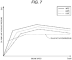
Patent document 1 has the following control problem. In the case where an engine speed is low, the oil pump cannot generate the hydraulic pressure that is equal to or higher than the actuation pressure of the oil jet mechanism even when the requested hydraulic pressure is set to be higher than the actuation pressure of the oil jet mechanism, and thus the amount of the injection oil that is required to cool the piston may not be secured. - As illustrated in
Fig. 7 , the oil pump is directly driven by the engine. Thus, a limit hydraulic pressure that can be generated by the oil pump is increased at a constant increase rate to the specified engine speed in the form of a linear function, and the increase rate is set to be lower than before at the specified engine speed and higher. - Meanwhile, as indicated by a broken line, the actuation pressure capable of delivering performance of the oil jet mechanism is regarded to have a specified set value coordinated such that the pressure is increased along with an increase in the engine speed.
- That is, due to a mechanism of the oil pump, in a situation where the engine speed is low, even in the case where the limit hydraulic pressure is reduced and the discharge volume capable of generating the target hydraulic pressure of the lubrication oil is set, the limit hydraulic pressure of the oil pump itself falls below the actuation pressure of the oil jet mechanism. Thus, it is difficult to secure the amount of the injection oil that is required to cool the piston.
- In addition, the limit hydraulic pressure of the oil pump tends to be reduced as an oil temperature of the lubrication oil is increased. Thus, when the oil temperature is high at the same engine speed, it is not easy to generate the hydraulic pressure that is equal to or higher than the actuation pressure of the oil jet mechanism. In particular, the piston made of iron has lower thermal conductivity than the piston made of an aluminum alloy though a structural strength thereof can be secured. Thus, it is difficult to diffuse heat of the iron piston, and cooling of such a piston tends to be insufficient. As a result, carbonization of the lubrication oil that is retained in a ring groove section or the like is concerned.
- As it has been described so far, depending on an engine operating situation such as the engine speed and the oil temperature, the hydraulic pressure of the oil that is injected by the oil jet mechanism cannot be secured. Thus, it is impossible to exert a sufficient cooling function.
- A purpose of the present invention is securing an amount of injection oil required to cool a piston regardless of an operating situation, and the like.
- An engine lubrication system includes: an automatic transmission; an oil pump that is driven by an engine; an oil jet mechanism that injects oil fed or pressure-fed by this oil pump to a piston; and control means that can set a target hydraulic pressure of the oil injected from this oil jet mechanism according to an operation state of the engine. The control means has a hydraulic pressure state determination section that can determine a hydraulic pressure state of the oil injected from the oil jet mechanism. The control means is configured to control the automatic transmission to downshift or is configured to change a gear stage of the automatic transmission to a lower gear stage, when the hydraulic pressure state determination section determines a hydraulic pressure insufficient state where an actual hydraulic pressure of the oil that is actually injected from the oil jet mechanism is insufficient for the target hydraulic pressure.
- In this engine lubrication system, the control means has the hydraulic pressure state determination section capable of determining the hydraulic pressure state of the oil that is injected from the oil jet mechanism. Thus, it is possible to determine the hydraulic pressure state of the oil that is actually injected from the oil jet mechanism.
- When the hydraulic pressure state determination section determines the hydraulic pressure insufficient state where the actual hydraulic pressure of the oil that is actually injected from the oil jet mechanism is insufficient for the target hydraulic pressure, the control means changes the gear stage of the automatic transmission to the lower gear stage. Thus, it is possible to increase a speed of the engine for driving the oil pump by using an existing gear shift function of the automatic transmission and thus to increase a limit hydraulic pressure of the oil pump.
- Particularly, the engine lubrication system includes hydraulic pressure detection means that can detect the hydraulic pressure of the oil injected from the oil jet mechanism. Further particularly, the hydraulic pressure state determination section determines the hydraulic pressure insufficient state in the case where a period in which a deviation between an actual hydraulic pressure detected by the hydraulic pressure detection means and the target hydraulic pressure is equal to or larger than a threshold value continues for a specified time. Further particularly, the hydraulic pressure state determination section is configured to determine the hydraulic pressure insufficient state in the case where a deviation between an actual hydraulic pressure detected by the hydraulic pressure detection means and the target hydraulic pressure is equal to or larger than a threshold value.
- According to this configuration, it is possible to directly determine the hydraulic pressure insufficient state by using the deviation between the hydraulic pressure of the oil that is pressure-fed from the oil pump and the target hydraulic pressure.
- Further particularly, the engine lubrication system includes oil temperature detection means that can detect a temperature of the oil injected from the oil jet mechanism. Further particularly, the hydraulic pressure state determination section determines the hydraulic pressure insufficient state in the case where the oil temperature that is detected by the oil temperature detection means is equal to or higher than a set temperature.
- According to this configuration, it is possible to indirectly determine the hydraulic pressure insufficient state by using the temperature of the oil that is pressure-fed from the oil pump as a parameter.
- Further particularly, the automatic transmission has a gear shift map capable of setting the gear stage that is established by using respective one of plural gear shift lines defined with a vehicle speed, particularly and a load as parameters, and, when the hydraulic pressure state determination section determines the hydraulic pressure insufficient state, the control means shifts at least one gear shift line of the plural gear shift lines, particularly to a higher speed side.
- According to this configuration, it is possible to secure the injection oil amount that is required to cool the piston by a simple configuration as shifting of the gear shift line.
- Further particularly, when the hydraulic pressure state determination section determines the hydraulic pressure insufficient state, the control means shifts the gear shift line for the highest gear stage among the plural gear shift lines, particularly to the higher speed side.
- According to this configuration, it is possible to secure the injection oil amount that is required to cool the piston while minimizing specification changes.
- Further particularly, the engine lubrication system includes automatic transmission oil temperature detection means that can detect an oil temperature of the automatic transmission. When the oil temperature of the automatic transmission that is detected by the automatic transmission oil temperature detection means is equal to or higher than an automatic transmission set temperature, the control means returns the gear stage, which has been changed to the lower gear stage, to the original gear stage.
- According to this configuration, it is possible to simultaneously secure the reliability of the automatic transmission and the injection oil amount of the oil jet mechanism.
- Further particularly, when the oil temperature of the automatic transmission that is detected by the automatic transmission oil temperature detection means is equal to or higher than the automatic transmission set temperature, the control means reduces engine output.
- According to this configuration, it is possible to actively reduce the engine speed and to further improve the reliability of the automatic transmission.
- Further particularly, a vehicle includes an engine, and the above engine lubrication system.
- Further particularly, a method of controlling the above engine lubrication system includes setting a target hydraulic pressure of the oil injected from the oil jet mechanism according to an operation state of the engine, determining a hydraulic pressure state of the oil injected from the oil jet mechanism, and controlling the automatic transmission to downshift or change a gear stage of the automatic transmission to a lower gear stage, when it is determined that an actual hydraulic pressure of the oil that is actually injected from the oil jet mechanism is insufficient for the target hydraulic pressure.
- Further particularly, a computer program product includes computer-readable instructions which, when loaded and executed on the above engine lubrication system, perform the above method.
- The above engine lubrication system can secure the injection oil amount that is required to cool the piston by using the existing gear shift function of the automatic transmission regardless of the operating situation.
-
- [
Fig. 1] Fig. 1 is a schematic configuration diagram of an engine lubrication system according to a first embodiment. - [
Fig. 2] Fig. 2 is a circuit diagram of a main section of the engine lubrication system. - [
Fig. 3] Fig. 3 is a gear shift map before a shift pattern is changed. - [
Fig. 4] Fig. 4 is a gear shift map after the shift pattern is changed. - [
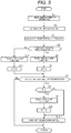
Fig. 5] Fig. 5 is a flowchart illustrating a procedure of shift pattern changing control processing. - [
Fig. 6] Fig. 6 is a map according to a modified embodiment that corresponds toFig. 4 . - [
Fig. 7] Fig. 7 is a graph illustrating a relationship between an engine speed and an oil pump limit hydraulic pressure. - A description will hereinafter be made on embodiments for carrying out the invention with reference to the drawings. The following description of preferred embodiments is essentially and merely illustrative and thus has no intention to limit the present invention, application subjects thereof, and application thereof.
- A description will hereinafter be made on a first embodiment of the present invention with reference to
Fig. 1 to Fig. 5 . - As illustrated in
Fig. 1 , an engine lubrication system S (a lubrication device) according to this first embodiment includes, as main components, anengine 1 particularly as a four-cylinder or six-cylinder diesel engine, anautomatic transmission 2, an electronic control unit (ECU) 3 (control means) for integrally controlling the lubrication system S,various sensors 41 to 47, and the like, for example. - First, a description will be made on the
engine 1. - In the
engine 1, particularly a cylinder head, a cylinder block, a crankcase, and an oil pan that collects and stores lubrication oil are vertically coupled to each other, and pistons, each of which is made of iron and can slide in respective one of cylinder bores, particularly six cylinder bores, formed in the cylinder block, and a crankshaft which is axially supported by the crankcase in a freely rotatable manner are coupled to each other by connecting rods (none of them are illustrated). - The
engine 1 particularly includes: amechanical oil pump 4 that is driven by rotation of the crankshaft and has a variable volume mechanism; and anoil feed passage 10 that is coupled to thisoil pump 4 and through which oil, a pressure of which is increased, as the lubrication oil is delivered to each lubrication portion of theengine 1. - As illustrated in
Fig. 2 , theoil feed passage 10 particularly includes: acommunication passage 11 that communicates with theoil pump 4 and extends in the cylinder block from the oil pan to the cylinder head; amain gallery 12 that is branched from thiscommunication passage 11 and extends in a cylinder arrangement direction; thehydraulic pressure sensor 45 that detects a hydraulic pressure of the oil pressure-fed in thismain gallery 12; a plurality of oil passages (not illustrated), each of which is branched from thecommunication passage 11 in the cylinder head; and the like. An oil strainer (not illustrated) that faces the oil pan is coupled to asuction port 4a of theoil pump 4. In thecommunication passage 11 that communicates with a discharge port 4b of theoil pump 4, apressure regulation valve 5 for theoil pump 4, anoil filter 13, anoil cooler 14, and the like are disposed in an order from an upstream side. - The
main gallery 12 particularly communicates with:oil supply sections 15a to 15g of for metal bearings disposed in seven journal bearing sections, each of which supports the crankshaft in a manner to allow free rotation thereof;oil supply sections 16a to 16g of the connecting rods; andoil jets 17a to 17f (oil jet mechanisms), each of which injects cooling oil to a back surface (inner surface) side of respective one of the six pistons. - Check
valves 18a to 18f, each of which restricts a flow of the oil to one direction toward respective one of theoil jets 17a to 17f, are disposed between themain gallery 12 and theoil jets 17a to 17f. - The
oil pump 4 is configured to be able to regulate a pump volume to a discharge volume that corresponds to a target hydraulic pressure in order to regulate the hydraulic pressure of the oil flowing through the oil feed passage 10 (the main gallery 12) to the target hydraulic pressure. - As illustrated in
Fig. 2 , theoil pump 4 particularly has a housing, adrive shaft 21, a pump element, acam ring 25, aspring 26, aring member 27, and the like. - The housing is configured to particularly include: a pump body that has a pump accommodating chamber; and a cover member that closes one side opening of this pump body. The
drive shaft 21 substantially penetrates a center of the pump accommodating chamber, is supported by the housing in a freely rotatable manner, and is rotationally driven by the crankshaft. - The pump element is particularly configured to include: a
rotor 22 that is accommodated in the pump accommodating chamber and a central portion of which is joined to thedrive shaft 21; and a plurality ofvanes 23, each of which is accommodated in respective one of a plurality of slits in a manner to freely and routinely appear, the plurality of slits being formed in an outer circumferential portion of thisrotor 22 by being notched radially. - The
cam ring 25 is arranged on an outer circumferential side of the pump element in a manner to be able to be eccentric to a rotation center of therotor 22, and cooperates with therotor 22 and an adjacent pair of thevanes 23 to define apump chamber 24. - As illustrated in
Fig. 2 , thespring 26 is an urging member that is accommodated in the pump body and constantly urges thecam ring 25 to a side where an eccentric amount thereof with respect to the rotation center of therotor 22 is increased. - The
ring member 27 includes a pair of ring-shaped members that are disposed in a freely slidable manner on both sides of an inner circumferential side of therotor 22 and each of which has a smaller diameter than therotor 22. In the housing, apressure chamber 28 that is defined by an inner circumferential surface of the housing and an outer circumferential surface of thecam ring 25 is formed. - The
oil pump 4 is particularly configured that, when the oil is introduced into thepressure chamber 28, thecam ring 25 swings on afulcrum 4a, therotor 22 becomes relatively eccentric to thecam ring 25, and the discharge volume of theoil pump 4 is changed. Regulation oil that is supplied to thepressure chamber 28 is supplied thereto from thecommunication passage 11, which communicates with the discharge port 4b, via thepressure regulation valve 5. - The
pressure regulation valve 5 constructed of a linear solenoid valve is driven by a drive duty ratio signal that is output from theECU 3. As the drive duty ratio is reduced, an amount of the oil supplied to thepressure chamber 28 is reduced, and a discharge amount of theoil pump 4 is increased. As the drive duty ratio is increased, the amount of the oil supplied to thepressure chamber 28 is increased, and the discharge amount of theoil pump 4 is reduced. - Next, a description will be made on the automatic transmission 20.
- As illustrated in
Fig. 1 , theautomatic transmission 2 is coupled to theengine 1, particularly through a torque converter (not illustrated) or through a clutch or directly. Particularly, the input shaft of theautomatic transmission 2 is coupled to the output shaft of theengine 1. Theautomatic transmission 2 may be a multispeed automatic transmission. Thisautomatic transmission 2 particularly establishes any of forward travel gears or gear stages (for example, a first gear to a sixth gear, i.e., the lowest gear to the highest gear, in a D range) and a reverse travel gear or gear stage to change a rotational frequency (i.e., a rotational speed) of acrankshaft 11 to a desired rotational frequency (i.e., speed), and transmits the desired rotational frequency to drive wheels (not illustrated). Here, a plurality of the forward travel gear stages only needs to exist, and is not limited to the first to sixth gear stages. - Next, a description will be made on the
ECU 3. - The
ECU 3 is configured to particularly include a central processing unit that runs various programs, memory (RAM, ROM), an input/output bus, and the like. ThisECU 3 is electrically connected to one or more sensors particularly aspeed sensor 41, avehicle speed sensor 42, an acceleratorpedal position sensor 43, anoil temperature sensor 44, thehydraulic pressure sensor 45, an ATFoil temperature sensor 46, and acoolant temperature sensor 47. - The
speed sensor 41 detects the speed of theengine 1 on the basis of the rotational frequency of the crankshaft, and outputs a detection signal. Thevehicle speed sensor 42 detects a travel speed on the basis of a rotational frequency of the wheel, and outputs a detection signal. The acceleratorpedal position sensor 43 detects a depression amount of an accelerator pedal (not illustrated), and outputs a detection signal. Theoil temperature sensor 44 detects a temperature of the oil that flows through theoil feed passage 11, and outputs a detection signal. Thehydraulic pressure sensor 45 detects a pressure of the oil that flows through theoil feed passage 11, and outputs a detection signal. The ATFoil temperature sensor 46 detects a temperature of actuation oil (ATF) in theautomatic transmission 2, and outputs a detection signal. Thecoolant temperature sensor 47 detects a coolant temperature in theengine 1, and outputs a detection signal. As illustrated inFig. 2 , in this embodiment, in order to detect an actual hydraulic pressure of the oil that is actually injected from each of theoil jets 17a to 17f with a high degree of accuracy, thehydraulic pressure sensor 45 is disposed at a position in themain gallery 12 near theoil jets 17a to 17f. - The
ECU 3 is configured that, when determining a hydraulic pressure insufficient state where the actual hydraulic pressure of the oil injected from each of theoil jets 17a to 17f is insufficient for the target hydraulic pressure, theECU 3 can execute shift pattern changing control for switching between gear shift maps M1, M2 of the automatic transmission 20. - As illustrated in
Fig. 1 , theECU 3 particularly includes afuel control section 31, a hydraulic pressurestate determination section 32, a gearshift control section 33, and the like as primary components. - First, a description will be made on the
fuel control section 31. - The
fuel control section 31 reads target torque of the engine via a target torque map (not illustrated) that is set in advance on the basis of an accelerator pedal position detected by the acceleratorpedal position sensor 43 and the engine speed detected by thespeed sensor 41, and reads a target fuel injection amount via a target fuel injection amount map (not illustrated) that is set in advance on the basis of this target torque, the engine speed, and the like. Then, thefuel control section 31 regulates an excitation time of a fuel injection valve on the basis of the set target fuel injection amount and a fuel pressure in a common rail, and thereby controls a fuel injection amount to be supplied to a combustion chamber in each of the cylinders. - When the ATF temperature of the
automatic transmission 2 that is detected by the ATFoil temperature sensor 46 is equal to or higher than an ATF set temperature (an automatic transmission set temperature), thefuel control section 31 executes torque down control for subtracting a fuel correction amount from the target fuel injection amount. The fuel correction amount is set to be increased as a deviation between the ATF temperature and the ATF set temperature is increased when the ATF temperature is equal to or higher than the ATF set temperature. This is because, when the ATF temperature becomes equal to or higher than the ATF set temperature, responsiveness is degraded, gear shift timing becomes off, lubricity is degraded, and the like, which degrades product reliability of theautomatic transmission 2. - Next, a description will be made on the hydraulic pressure
state determination section 32. - The hydraulic pressure
state determination section 32 calculates the target hydraulic pressure of the oil that is injected from each of theoil jets 17a to 17f. Here, in this embodiment, the target hydraulic pressure is a hydraulic pressure for generating the flow speed (an injection speed) that is required to secure an injection oil amount when the injection oil amount that is required for cooling the piston is injected from each of theoil jets 17a to 17f to the respective piston. - The hydraulic pressure
state determination section 32 has: a simulation model formula with which it is possible to estimate a piston temperature by using one or more elements, particularly five elements of the engine speed, an engine load (or the accelerator pedal position), the oil temperature, the engine coolant temperature, and an actual fuel injection amount; and a target hydraulic pressure map (not illustrated) that defines a corresponding relationship between the target hydraulic pressure required to cool the piston to a specified target temperature and the piston temperature. The hydraulic pressurestate determination section 32 estimates the piston temperature by applying output values from thesensors fuel control section 31 to the model formula, and calculates the target hydraulic pressure by applying the estimated piston temperature to the target hydraulic pressure map. - The hydraulic pressure
state determination section 32 is configured to be able to determine the hydraulic pressure insufficient state. - The hydraulic pressure
state determination section 32 determines the hydraulic pressure insufficient state in the case where the actual hydraulic pressure that is detected by thehydraulic pressure sensor 45 is equal to or lower than the target hydraulic pressure that is acquired by the calculation and a period in which a deviation therebetween is equal to or larger than a threshold value continues for a specified time (for example, one to two seconds). In addition, the hydraulic pressurestate determination section 32 determines the hydraulic pressure insufficient state in the case where the oil temperature that is detected by theoil temperature sensor 44 is equal to or higher than a set temperature. - Next, a description will be made on the gear
shift control section 33. - The gear
shift control section 33 has one or more maps, particularly the first and second gear shift maps M1, M2 in each of which a shift pattern is set in advance on the basis of the travel speed of the vehicle and the accelerator pedal position. - As illustrated in
Fig. 3 , in the first gear shift map M1, one or more gear shift lines that define upshifts or shift-ups (solid lines) from the first gear (i.e., the gear of the highest gear ratio) to the sixth gear (i.e., the gear of the lowest gear ratio) and gear shift lines that define downshifts, or shift-downs (broken lines) during normal travel are set. As illustrated inFig. 4 , in the second gear shift map M2, gear shift lines that define the shift-ups (solid lines) from the first gear to the sixth gear and gear shift lines that define the shift-downs (broken lines) in the hydraulic pressure insufficient state are set. A difference therebetween is particularly a point that the entire sixth gear shift line for the shift-up to the sixth gear as the highest gear stage in the second gear shift map M2 is shifted to a higher vehicle speed side than the sixth gear shift line for the shift-up to the sixth gear in the first gear shift map M1. - During the normal travel, the gear
shift control section 33 reads the gear stage as a switching destination via the first gear shift map M1, and subjects a gear-shift solenoid valve (not illustrated) to on/off control. Then, the gearshift control section 33 switches a spool position of each shift valve via the gear-shift solenoid valve, and fastens friction fastening elements to be combined for corresponding one of the gear stages. - In addition, when the hydraulic pressure
state determination section 32 determines the hydraulic pressure insufficient state, the gearshift control section 33 executes the shift pattern changing control for changing the gear shift map from the first gear shift map M1 to the second gear shift map M2 and reading the gear stage as the switching destination via this second gear shift map M2. - When the first gear shift map M1 is selected, 0 is assigned to a flag F. When the second gear shift map M2 is selected, 1 is assigned to the flag F.
- By executing the shift pattern changing control, a travel state is changed from a state where the vehicle travels at the sixth gear by using the first gear shift map M1 to a state where the vehicle travels at the fifth gear by using the second gear shift map M2, and the speed of the
engine 1 is increased. - In the case where the ATF oil temperature that is detected by the ATF
oil temperature sensor 46 is equal to or higher than the ATF set temperature, the gearshift control section 33 particularly executes the shift pattern changing control to return the gear stage, which has been changed to the lower gear stage, to the original gear stage. More specifically, when the hydraulic pressurestate determination section 32 determines the hydraulic pressure insufficient state, the travel state is changed from the state where the vehicle travels at the fifth gear by using the second gear shift map M2 to the state where the vehicle travels at the sixth gear by using the first gear shift map M1, and the speed of theengine 1 is reduced. - Next, a description will be made on an exemplary procedure of shift pattern changing control processing that is executed particularly by the ECU 40 with reference to a flowchart illustrated in
Fig. 5 . In the drawing, Si (i = 1, 2,...) represents each step. All of the steps as disclosed inFig. 5 are not necessarily essential. - First, in S1, the ECU 40 particularly reads the one or various signals that are input from the
sensors 41 to 47, the one or various control maps, and the like, and then processing proceeds to S2. - In S2, the simulation is particularly used to estimate the piston temperature. Then, by using the estimated piston temperature and the target hydraulic pressure map, the target hydraulic pressure that corresponds to the injection oil amount that is required to cool the piston is calculated (S3).
- Next, it is determined whether the hydraulic pressure of the oil that is fed or pressure-fed from the
oil pump 4 is in the hydraulic pressure insufficient state (S4). The hydraulic pressure insufficient state is particularly determined in the case where the period in which the deviation between the actual hydraulic pressure and the target hydraulic pressure of the oil is equal to or larger than the threshold value continues for the specified time or in the case where the oil temperature is equal to or higher than the set temperature. - As a result of the determination in S4, if it is determined as the hydraulic pressure insufficient state, the second gear shift map M2 is selected to increase the engine speed and thereby increase the discharge volume of the oil pump 4 (S5). Then, after 1 is assigned to the flag F (S6), the processing proceeds to S7. By changing the travel state from the sixth-gear travel state to the fifth-gear travel state, i.e., by downshift to increase the rotational speed of the input shaft of the
automatic transmission 2, the speed of theengine 1 is increased, and the limit hydraulic pressure of theoil pump 4 is increased to exceed the actuation pressure of each of theoil jets 17a to 17f. - As the result of the determination in S4, if it is not determined as the hydraulic pressure insufficient state, there is no need to increase the discharge volume of the
oil pump 4 by increasing the engine speed. Thus, the first gear shift map M1 is selected (S12). Then, after 0 is assigned to the flag F (S13), the processing proceeds to S7. - In S7, it is determined whether the ATF temperature is equal to or higher than the ATF set temperature.
- As a result of the determination in S7, if the ATF temperature is equal to or higher than the ATF set temperature, the product reliability of the
automatic transmission 2 is possibly degraded. Thus, the processing proceeds to S8. As the result of the determination in S7, if the ATF temperature is lower than the ATF set temperature, there is no possibility that the product reliability of theautomatic transmission 2 is degraded. Thus, the processing returns without executing the torque down control. - In S8, it is determined whether the flag F is 1.
- As a result of the determination in S8, if the flag F is 1, the second gear shift map M2 has already been selected. Thus, the first gear shift map M1 is selected instead of the second gear shift map M2 (S9). Then, after 0 is assigned to the flag F (S10), the processing proceeds to S11. In the shift pattern changing control using the second gear shift map M2, the ATF temperature is further increased along with an increase in the engine speed. Thus, the shift pattern changing control returns to the normal control using the first gear shift map M1, and the increase in the ATF temperature is thereby suppressed.
- In S11, the torque down control is executed, and then the processing returns.
- In the torque down control, the fuel injection amount is reduced for correction. In this way, the engine speed is reduced to actively reduce the ATF temperature.
- Next, a description will be made on action and effects of the lubrication system S for the
engine 1. - According to this lubrication system S for the
engine 1, theECU 3 has the hydraulic pressurestate determination section 32 capable of determining the hydraulic pressure state of the oil that is injected from each of theoil jets 17a to 17f. Thus, it is possible to determine the hydraulic pressure state of the oil that is actually injected from each of theoil jets 17a to 17f. When the hydraulic pressurestate determination section 32 determines the hydraulic pressure insufficient state where the actual hydraulic pressure of the oil that is injected from each of theoil jets 17a to 17f is insufficient for the target hydraulic pressure, theECU 3 changes the gear stage of theautomatic transmission 2 to the lower gear stage. Thus, it is possible to increase the speed of theengine 1 for driving theoil pump 4 by using an existing gear shift function of theautomatic transmission 2 and thus to increase the limit hydraulic pressure of theoil pump 4. Therefore, even when the piston is the iron piston with low thermal conductivity, it is possible to avoid carbonization of the lubrication oil in a ring groove section or the like. - The
hydraulic pressure sensor 45 capable of detecting the hydraulic pressure of the oil that is injected from each of theoil jets 17a to 17f is provided. The hydraulic pressurestate determination section 32 determines the hydraulic pressure insufficient state in the case where the period in which the deviation between the actual hydraulic pressure that is detected by thehydraulic pressure sensor 45 and the target hydraulic pressure is equal to or larger than the threshold value continues for the specified time. - In this way, it is possible to directly determine the hydraulic pressure insufficient state by using the deviation between the hydraulic pressure of the oil that is pressure-fed from the
oil pump 4 and the target hydraulic pressure. - The
oil temperature sensor 44 capable of detecting the temperature of the oil that is injected from each of theoil jets 17a to 17f is provided. The hydraulic pressurestate determination section 32 determines the hydraulic pressure insufficient state in the case where the oil temperature that is detected by theoil temperature sensor 44 is equal to or higher than the set temperature. In this way, it is possible to indirectly determine the hydraulic pressure insufficient state by using the temperature of the oil that is pressure-fed from theoil pump 4 as a parameter. - The
automatic transmission 2 has the first and second gear shift maps M1, M2 capable of setting the gear stage that can be established by using any of the plural gear shift lines defined with the vehicle speed and, particularly, the accelerator pedal position (or the load) as parameters. When the hydraulic pressurestate determination section 32 determines the hydraulic pressure insufficient state, theECU 3 shifts at least one of the plural gear shift lines to the higher speed side. Thus, it is possible to secure the injection oil amount that is required to cool the piston by a simple configuration as shifting of the gear shift lines. - When the hydraulic pressure
state determination section 32 determines the hydraulic pressure insufficient state, theECU 3 shifts the sixth gear shift line for the shift-up to the sixth gear as the highest gear stage among the plural gear shift lines to the higher speed side. Thus, it is possible to secure the injection oil amount that is required to cool the piston while minimizing specification changes. - The ATF
oil temperature sensor 46 capable of detecting the oil temperature of theautomatic transmission 2 is provided. When the ATF oil temperature of theautomatic transmission 2 that is detected by the ATFoil temperature sensor 46 is equal to or higher than the ATF set temperature, theECU 3 returns the gear stage, which has been changed to the lower gear stage, to the original gear stage. Thus, it is possible to simultaneously secure the reliability of theautomatic transmission 2 and the injection oil amount of each of theoil jets 17a to 17f. - When the ATF oil temperature that is detected by the ATF
oil temperature sensor 46 is equal to or higher than the ATF set temperature, the engine output is reduced. Thus, it is possible to actively reduce the engine speed and to further improve the reliability of the automatic transmission. - Next, a description will be made on a lubrication system SA according to a second embodiment with reference to
Fig. 6 . - In the first embodiment, the entire sixth gear shift line for the shift-up to the sixth gear has the completely different patterns in the first gear shift map M1 selected during the normal travel and the second gear shift map M2 selected in the hydraulic pressure insufficient state. In the second embodiment, the sixth gear shift line has partially different patterns in the first gear shift map M1 and a second gear shift map M3.
- As illustrated in
Fig. 6 , in the second gear shift map M3, gear shift lines that define the shift-ups (solid lines) from the first gear to the sixth gear and gear shift lines that define the shift-downs (broken lines) in the hydraulic pressure insufficient state are set. The sixth gear shift line in the second gear shift map M3 is set by partially shifting a low-load range of the sixth gear shift line in the first gear shift map M1 to the higher vehicle speed side. The rest of the region is the same. In this way, it is possible to minimize the specification changes. - In addition, a shifting amount to the higher vehicle speed side may be increased as the deviation between the actual hydraulic pressure that is detected by the
hydraulic pressure sensor 45 and the target hydraulic pressure is increased (see a one-dot chain line inFig. 6 ). In this way, the hydraulic pressure insufficient state can promptly be canceled. - Next, a description will be made on modified embodiments in which the embodiment described above is partially modified.
- 1] In the above embodiment, the description has been made on the example of the
automatic transmission 2 capable of shifting the gear among the first gear to the sixth gear in the D range on the basis of the gear shift map. However, the shift patterns only need to be set by the gear shift lines, and the specification of the transmission such as the number of the gear stages can be set arbitrarily. - 2] In the above embodiment, the description has been made on the example in which it is determined as the hydraulic pressure insufficient state in the case where the period in which the deviation between the actual hydraulic pressure and the target hydraulic pressure of the oil is equal to or larger than the threshold value continues for the specified time. However, the threshold value and the specified time can be set to have any values according to specifications of the oil jets. The description has been made on the example in which it is determined as the hydraulic pressure insufficient state in the case where the oil temperature is equal to or higher than the set temperature. However, the set temperature can be set to have any value according to the specifications of the oil jets. Furthermore, the description has been made on the example in which it is determined as the hydraulic pressure insufficient state in the case where the period in which the deviation between the actual hydraulic pressure and the target hydraulic pressure of the oil is equal to or larger than the threshold value continues for the specified time or in the case where the oil temperature is equal to or higher than the set temperature. However, the hydraulic pressure insufficient state may be determined by using any one of the above cases.
- 3] In the above embodiment, the description has been made on the example in which the piston temperature is first estimated, and the target hydraulic pressure is calculated by applying the estimated piston temperature to the target hydraulic pressure map. However, the step of estimating the piston temperature may be eliminated, and the target hydraulic pressure may directly be calculated by using the output values from the
sensors fuel control section 31. - 4] In the above embodiment, the description has been made on the example in which, when the hydraulic pressure insufficient state is determined, the sixth gear shift line as the highest gear stage is only changed. However, the gear shift line for the highest gear stage only needs to be shifted to the higher side, and the gear shift line for the fifth gear or lower that is not the highest gear stage may be shifted to the higher side.
- 5] In addition to the above, those skilled in the art can implement a mode, in which various modifications are added to the embodiment, or a mode, in which the embodiments are combined, without departing from the gist of the present invention, and the present invention includes such modified modes.
-
- 1:
- Engine
- 2:
- Automatic transmission
- 3:
- ECU
- 4:
- Oil pump
- 17a to 17f:
- Oil jet
- 32:
- Hydraulic pressure state determination section
- 44:
- Oil temperature sensor
- 45:
- Hydraulic pressure sensor
- 46:
- ATF oil temperature sensor
- M1:
- First gear shift map
- M2, M3:
- Second gear shift map
- S, SA:
- Lubrication system
Claims (15)
- An engine lubrication system (S) comprising:an automatic transmission (2);an oil pump (4) configured to be driven by an engine (1);an oil jet mechanism (17a to 17f) configured to inject oil fed or pressure-fed by the oil pump (4) to a piston; andcontrol means (3) configured to set a target hydraulic pressure of the oil injected from the oil jet mechanism (17a to 17f) according to an operation state of the engine (1), whereinthe control means (3) has a hydraulic pressure state determination section (32) configured to determine a hydraulic pressure state of the oil injected from the oil jet mechanism (17a to 17f), andthe control means (3) is configured to control the automatic transmission (2) to downshift or is configured to change a gear stage of the automatic transmission (2) to a lower gear stage, when the hydraulic pressure state determination section (32) determines a hydraulic pressure insufficient state where an actual hydraulic pressure of the oil that is actually injected from the oil jet mechanism (17a to 17f) is insufficient for the target hydraulic pressure.
- The engine lubrication system (S) according to claim 1 further comprising:
hydraulic pressure detection means (45) configured to detect the hydraulic pressure of the oil injected from the oil jet mechanism (17a to 17f). - The engine lubrication system (S) according to claim 2, wherein
the hydraulic pressure state determination section (32) is configured to determine the hydraulic pressure insufficient state in the case where a period in which a deviation between an actual hydraulic pressure detected by the hydraulic pressure detection means (45) and the target hydraulic pressure is equal to or larger than a threshold value continues for a specified time. - The engine lubrication system (S) according to claim 2, wherein
the hydraulic pressure state determination section (32) is configured to determine the hydraulic pressure insufficient state in the case where a deviation between an actual hydraulic pressure detected by the hydraulic pressure detection means (45) and the target hydraulic pressure is equal to or larger than a threshold value. - The engine lubrication system (S) according to any one of the preceding claims further comprising:oil temperature detection means (44) configured to detect a temperature of the oil injected from the oil jet mechanism (17a to 17f), particularly whereinthe hydraulic pressure state determination section (32) is configured to determine the hydraulic pressure insufficient state in the case where the oil temperature that is detected by the oil temperature detection means (44) is equal to or higher than a set temperature.
- The engine lubrication system (S) according to any one of the preceding claims, wherein
the automatic transmission (2) has a gear shift map configured to set the gear stage that is established by using respective one of plural gear shift lines defined with a vehicle speed, and
when the hydraulic pressure state determination section (32) determines the hydraulic pressure insufficient state, the control means (3) is configured to shift at least one gear shift line of the plural gear shift lines. - The engine lubrication system (S) according to claim 6, wherein
the respective one of plural gear shift lines are defined with the vehicle speed and a load as parameters. - The engine lubrication system (S) according to claim 6 or 7, wherein
when the hydraulic pressure state determination section (32) determines the hydraulic pressure insufficient state, the control means (3) is configured to shift at least one gear shift line of the plural gear shift lines to a higher speed side. - The engine lubrication system (S) according to any one of claims 6 to 8, wherein
when the hydraulic pressure state determination section (32) determines the hydraulic pressure insufficient state, the control means (3) is configured to shift the gear shift line for the highest gear stage among the plural gear shift lines. - The engine lubrication system (S) according to claim 9, wherein
when the hydraulic pressure state determination section (32) determines the hydraulic pressure insufficient state, the control means (3) is configured to shift the gear shift line for the highest gear stage among the plural gear shift lines to the higher speed side. - The engine lubrication system (S) according to any one of the preceding claims further comprising:automatic transmission oil temperature detection means (46) configured to detect an oil temperature of the automatic transmission (2), whereinwhen the oil temperature of the automatic transmission (2) that is detected by the automatic transmission oil temperature detection means (46) is equal to or higher than an automatic transmission set temperature, the control means (3) is configured to returns the gear stage, which has been changed to the lower gear stage, to the original gear stage.
- The engine lubrication system (S) according to claim 11, wherein
when the oil temperature of the automatic transmission (2) that is detected by the automatic transmission oil temperature detection means (46) is equal to or higher than the automatic transmission set temperature, the control means (3) is configured to reduce engine output. - A vehicle comprising:an engine (1); andthe engine lubrication system (S) according to any one of the preceding claims.
- A method of controlling an engine lubrication system (S) which includes an automatic transmission (2), an oil pump (4) configured to be driven by an engine (1), an oil jet mechanism (17a to 17f) configured to inject oil pressure-fed by the oil pump (4) to a piston, comprising:setting a target hydraulic pressure of the oil injected from the oil jet mechanism (17a to 17f) according to an operation state of the engine (1);determining a hydraulic pressure state of the oil injected from the oil jet mechanism (17a to 17f); andcontrolling the automatic transmission (2) to downshift or change a gear stage of the automatic transmission (2) to a lower gear stage, when it is determined that an actual hydraulic pressure of the oil that is actually injected from the oil jet mechanism (17a to 17f) is insufficient for the target hydraulic pressure.
- A computer program product comprising computer-readable instructions which, when loaded and executed on the engine lubrication system (S) according to any one of claims 1 to 12, perform a method of claim 14.
Applications Claiming Priority (1)
| Application Number | Priority Date | Filing Date | Title |
|---|---|---|---|
| JP2019136839A JP7273367B2 (en) | 2019-07-25 | 2019-07-25 | engine lubricator |
Publications (2)
| Publication Number | Publication Date |
|---|---|
| EP3770384A1 true EP3770384A1 (en) | 2021-01-27 |
| EP3770384B1 EP3770384B1 (en) | 2021-09-29 |
Family
ID=71661646
Family Applications (1)
| Application Number | Title | Priority Date | Filing Date |
|---|---|---|---|
| EP20186095.4A Active EP3770384B1 (en) | 2019-07-25 | 2020-07-16 | Engine lubrication system, engine, method of controlling engine lubrication system, and computer program product |
Country Status (3)
| Country | Link |
|---|---|
| US (1) | US10988141B2 (en) |
| EP (1) | EP3770384B1 (en) |
| JP (1) | JP7273367B2 (en) |
Cited By (2)
| Publication number | Priority date | Publication date | Assignee | Title |
|---|---|---|---|---|
| CN114228726A (en) * | 2021-11-25 | 2022-03-25 | 中联重科股份有限公司 | Control method, controller, control device and engineering equipment for engineering equipment |
| CN114838122A (en) * | 2022-03-29 | 2022-08-02 | 中国人民解放军陆军装甲兵学院 | On-ring fault detection system and method for gearbox gear shifting hydraulic system |
Families Citing this family (4)
| Publication number | Priority date | Publication date | Assignee | Title |
|---|---|---|---|---|
| US11746893B2 (en) * | 2020-09-30 | 2023-09-05 | Eaton Cummins Automated Transmission Technologies | Thermal management of a vehicle transmission |
| JP7762231B2 (en) * | 2022-01-12 | 2025-10-29 | Astemo株式会社 | Internal combustion engine control device and internal combustion engine control method |
| FR3136807B1 (en) * | 2022-06-17 | 2024-06-21 | Safran Trans Systems | LUBRICATION MODULE FOR A TURBOMACHINE LUBRICATION STATION |
| CN117984985B (en) * | 2023-11-27 | 2024-11-01 | 赛力斯汽车有限公司 | Hybrid electric vehicle control method, device and hybrid electric vehicle |
Citations (4)
| Publication number | Priority date | Publication date | Assignee | Title |
|---|---|---|---|---|
| DE4332456A1 (en) * | 1993-09-23 | 1995-03-30 | Bayerische Motoren Werke Ag | System for a motor vehicle with an internal combustion engine fitted with a catalytic converter |
| FR2890926A1 (en) * | 2005-09-21 | 2007-03-23 | Renault Sas | METHOD FOR OBTAINING EXHAUST GASES FUEL-LOADED |
| DE102013201266A1 (en) * | 2013-01-28 | 2014-07-31 | Zf Friedrichshafen Ag | Method for increasing efficiency of adjustable hydraulic pump of gear box, involves driving gear box by comparing delivery rates of pump to reach current demand for oil and shortening switching times by reducing pressure break-down |
| JP2018189022A (en) | 2017-05-01 | 2018-11-29 | トヨタ自動車株式会社 | Hydraulic control device |
Family Cites Families (6)
| Publication number | Priority date | Publication date | Assignee | Title |
|---|---|---|---|---|
| US4856628A (en) * | 1987-11-17 | 1989-08-15 | Hino Jidosha Kogyo Kabushiki Kaisha | Automated mechanical transmission system for use in commercial vehicles |
| US20120090580A1 (en) * | 2010-10-15 | 2012-04-19 | Lung Tan Hu | Controlled-compression direct-power-cycle engine |
| JP6094430B2 (en) | 2013-08-28 | 2017-03-15 | マツダ株式会社 | Engine control device |
| JP6280330B2 (en) | 2013-08-30 | 2018-02-14 | ダイハツ工業株式会社 | Vehicle control device |
| JP6319194B2 (en) | 2015-06-08 | 2018-05-09 | マツダ株式会社 | Engine oil supply device |
| JP2020066369A (en) * | 2018-10-25 | 2020-04-30 | トヨタ自動車株式会社 | Control device for hybrid vehicle |
-
2019
- 2019-07-25 JP JP2019136839A patent/JP7273367B2/en active Active
-
2020
- 2020-07-16 EP EP20186095.4A patent/EP3770384B1/en active Active
- 2020-07-16 US US16/930,368 patent/US10988141B2/en active Active
Patent Citations (4)
| Publication number | Priority date | Publication date | Assignee | Title |
|---|---|---|---|---|
| DE4332456A1 (en) * | 1993-09-23 | 1995-03-30 | Bayerische Motoren Werke Ag | System for a motor vehicle with an internal combustion engine fitted with a catalytic converter |
| FR2890926A1 (en) * | 2005-09-21 | 2007-03-23 | Renault Sas | METHOD FOR OBTAINING EXHAUST GASES FUEL-LOADED |
| DE102013201266A1 (en) * | 2013-01-28 | 2014-07-31 | Zf Friedrichshafen Ag | Method for increasing efficiency of adjustable hydraulic pump of gear box, involves driving gear box by comparing delivery rates of pump to reach current demand for oil and shortening switching times by reducing pressure break-down |
| JP2018189022A (en) | 2017-05-01 | 2018-11-29 | トヨタ自動車株式会社 | Hydraulic control device |
Cited By (3)
| Publication number | Priority date | Publication date | Assignee | Title |
|---|---|---|---|---|
| CN114228726A (en) * | 2021-11-25 | 2022-03-25 | 中联重科股份有限公司 | Control method, controller, control device and engineering equipment for engineering equipment |
| CN114838122A (en) * | 2022-03-29 | 2022-08-02 | 中国人民解放军陆军装甲兵学院 | On-ring fault detection system and method for gearbox gear shifting hydraulic system |
| CN114838122B (en) * | 2022-03-29 | 2023-10-27 | 中国人民解放军陆军装甲兵学院 | A fault detection system and method for in-the-loop transmission shift hydraulic system |
Also Published As
| Publication number | Publication date |
|---|---|
| JP7273367B2 (en) | 2023-05-15 |
| EP3770384B1 (en) | 2021-09-29 |
| JP2021021349A (en) | 2021-02-18 |
| US10988141B2 (en) | 2021-04-27 |
| US20210024070A1 (en) | 2021-01-28 |
Similar Documents
| Publication | Publication Date | Title |
|---|---|---|
| EP3770384B1 (en) | Engine lubrication system, engine, method of controlling engine lubrication system, and computer program product | |
| RU2674854C2 (en) | Method (versions) and system for oil supply into internal combustion engine | |
| EP2216568B1 (en) | Abnormality determination apparatus and abnormality determination method for oil temperature sensor | |
| US8439796B2 (en) | Methods and systems for turbocharger control | |
| CN102003292B (en) | There is the motor of hydraulic variable valve timing | |
| RU2704369C2 (en) | Method for determining air-fuel ratio imbalance (embodiments) | |
| US20170350304A1 (en) | Piston cooling device | |
| JP6084991B2 (en) | Hydraulic transmission device for automatic transmission | |
| JP2009030616A (en) | Fuel injection control device for cold engine at low temperature | |
| KR100892894B1 (en) | Control apparatus for vehicle and method of controlling vehicle | |
| US10196065B2 (en) | Vehicle control system | |
| US6352061B2 (en) | Control device for a variable valve timing mechanism of an engine | |
| US10788038B2 (en) | Control device for internal combustion engine | |
| JP5854022B2 (en) | Oil jet device for internal combustion engine | |
| US8985073B2 (en) | Oil supply apparatus for internal combustion engine | |
| CN103225528A (en) | Oil pressure scheduling based on engine acceleration | |
| JP2024030613A (en) | Vehicle control device | |
| US7220214B2 (en) | Shift control system for automatic transmission | |
| JP2007127076A (en) | Abnormality diagnosis apparatus for in-cylinder internal combustion engine | |
| JP2013044241A (en) | Warning device | |
| CN109667641A (en) | For monitoring the method and driving assembly of the characteristic of engine oil | |
| JP6787686B2 (en) | Hydraulic control device | |
| JP2013231365A (en) | Control device of internal combustion engine | |
| US11149632B1 (en) | Engine system with variable compression ratio mechanism and method for operation of said system | |
| JP6280330B2 (en) | Vehicle control device |
Legal Events
| Date | Code | Title | Description |
|---|---|---|---|
| PUAI | Public reference made under article 153(3) epc to a published international application that has entered the european phase |
Free format text: ORIGINAL CODE: 0009012 |
|
| STAA | Information on the status of an ep patent application or granted ep patent |
Free format text: STATUS: THE APPLICATION HAS BEEN PUBLISHED |
|
| STAA | Information on the status of an ep patent application or granted ep patent |
Free format text: STATUS: REQUEST FOR EXAMINATION WAS MADE |
|
| AK | Designated contracting states |
Kind code of ref document: A1 Designated state(s): AL AT BE BG CH CY CZ DE DK EE ES FI FR GB GR HR HU IE IS IT LI LT LU LV MC MK MT NL NO PL PT RO RS SE SI SK SM TR |
|
| AX | Request for extension of the european patent |
Extension state: BA ME |
|
| 17P | Request for examination filed |
Effective date: 20210114 |
|
| RBV | Designated contracting states (corrected) |
Designated state(s): AL AT BE BG CH CY CZ DE DK EE ES FI FR GB GR HR HU IE IS IT LI LT LU LV MC MK MT NL NO PL PT RO RS SE SI SK SM TR |
|
| GRAP | Despatch of communication of intention to grant a patent |
Free format text: ORIGINAL CODE: EPIDOSNIGR1 |
|
| STAA | Information on the status of an ep patent application or granted ep patent |
Free format text: STATUS: GRANT OF PATENT IS INTENDED |
|
| RIC1 | Information provided on ipc code assigned before grant |
Ipc: F01M 1/00 20060101AFI20210519BHEP Ipc: F16H 61/16 20060101ALI20210519BHEP Ipc: F16H 61/02 20060101ALI20210519BHEP |
|
| INTG | Intention to grant announced |
Effective date: 20210618 |
|
| GRAS | Grant fee paid |
Free format text: ORIGINAL CODE: EPIDOSNIGR3 |
|
| GRAA | (expected) grant |
Free format text: ORIGINAL CODE: 0009210 |
|
| STAA | Information on the status of an ep patent application or granted ep patent |
Free format text: STATUS: THE PATENT HAS BEEN GRANTED |
|
| AK | Designated contracting states |
Kind code of ref document: B1 Designated state(s): AL AT BE BG CH CY CZ DE DK EE ES FI FR GB GR HR HU IE IS IT LI LT LU LV MC MK MT NL NO PL PT RO RS SE SI SK SM TR |
|
| REG | Reference to a national code |
Ref country code: GB Ref legal event code: FG4D |
|
| REG | Reference to a national code |
Ref country code: CH Ref legal event code: EP Ref country code: AT Ref legal event code: REF Ref document number: 1434374 Country of ref document: AT Kind code of ref document: T Effective date: 20211015 |
|
| REG | Reference to a national code |
Ref country code: DE Ref legal event code: R096 Ref document number: 602020000636 Country of ref document: DE |
|
| REG | Reference to a national code |
Ref country code: IE Ref legal event code: FG4D |
|
| REG | Reference to a national code |
Ref country code: LT Ref legal event code: MG9D |
|
| PG25 | Lapsed in a contracting state [announced via postgrant information from national office to epo] |
Ref country code: FI Free format text: LAPSE BECAUSE OF FAILURE TO SUBMIT A TRANSLATION OF THE DESCRIPTION OR TO PAY THE FEE WITHIN THE PRESCRIBED TIME-LIMIT Effective date: 20210929 Ref country code: HR Free format text: LAPSE BECAUSE OF FAILURE TO SUBMIT A TRANSLATION OF THE DESCRIPTION OR TO PAY THE FEE WITHIN THE PRESCRIBED TIME-LIMIT Effective date: 20210929 Ref country code: NO Free format text: LAPSE BECAUSE OF FAILURE TO SUBMIT A TRANSLATION OF THE DESCRIPTION OR TO PAY THE FEE WITHIN THE PRESCRIBED TIME-LIMIT Effective date: 20211229 Ref country code: LT Free format text: LAPSE BECAUSE OF FAILURE TO SUBMIT A TRANSLATION OF THE DESCRIPTION OR TO PAY THE FEE WITHIN THE PRESCRIBED TIME-LIMIT Effective date: 20210929 Ref country code: BG Free format text: LAPSE BECAUSE OF FAILURE TO SUBMIT A TRANSLATION OF THE DESCRIPTION OR TO PAY THE FEE WITHIN THE PRESCRIBED TIME-LIMIT Effective date: 20211229 Ref country code: SE Free format text: LAPSE BECAUSE OF FAILURE TO SUBMIT A TRANSLATION OF THE DESCRIPTION OR TO PAY THE FEE WITHIN THE PRESCRIBED TIME-LIMIT Effective date: 20210929 Ref country code: RS Free format text: LAPSE BECAUSE OF FAILURE TO SUBMIT A TRANSLATION OF THE DESCRIPTION OR TO PAY THE FEE WITHIN THE PRESCRIBED TIME-LIMIT Effective date: 20210929 |
|
| REG | Reference to a national code |
Ref country code: NL Ref legal event code: MP Effective date: 20210929 |
|
| REG | Reference to a national code |
Ref country code: AT Ref legal event code: MK05 Ref document number: 1434374 Country of ref document: AT Kind code of ref document: T Effective date: 20210929 |
|
| PG25 | Lapsed in a contracting state [announced via postgrant information from national office to epo] |
Ref country code: LV Free format text: LAPSE BECAUSE OF FAILURE TO SUBMIT A TRANSLATION OF THE DESCRIPTION OR TO PAY THE FEE WITHIN THE PRESCRIBED TIME-LIMIT Effective date: 20210929 Ref country code: GR Free format text: LAPSE BECAUSE OF FAILURE TO SUBMIT A TRANSLATION OF THE DESCRIPTION OR TO PAY THE FEE WITHIN THE PRESCRIBED TIME-LIMIT Effective date: 20211230 |
|
| PG25 | Lapsed in a contracting state [announced via postgrant information from national office to epo] |
Ref country code: AT Free format text: LAPSE BECAUSE OF FAILURE TO SUBMIT A TRANSLATION OF THE DESCRIPTION OR TO PAY THE FEE WITHIN THE PRESCRIBED TIME-LIMIT Effective date: 20210929 |
|
| PG25 | Lapsed in a contracting state [announced via postgrant information from national office to epo] |
Ref country code: IS Free format text: LAPSE BECAUSE OF FAILURE TO SUBMIT A TRANSLATION OF THE DESCRIPTION OR TO PAY THE FEE WITHIN THE PRESCRIBED TIME-LIMIT Effective date: 20220129 Ref country code: SK Free format text: LAPSE BECAUSE OF FAILURE TO SUBMIT A TRANSLATION OF THE DESCRIPTION OR TO PAY THE FEE WITHIN THE PRESCRIBED TIME-LIMIT Effective date: 20210929 Ref country code: RO Free format text: LAPSE BECAUSE OF FAILURE TO SUBMIT A TRANSLATION OF THE DESCRIPTION OR TO PAY THE FEE WITHIN THE PRESCRIBED TIME-LIMIT Effective date: 20210929 Ref country code: PT Free format text: LAPSE BECAUSE OF FAILURE TO SUBMIT A TRANSLATION OF THE DESCRIPTION OR TO PAY THE FEE WITHIN THE PRESCRIBED TIME-LIMIT Effective date: 20220131 Ref country code: PL Free format text: LAPSE BECAUSE OF FAILURE TO SUBMIT A TRANSLATION OF THE DESCRIPTION OR TO PAY THE FEE WITHIN THE PRESCRIBED TIME-LIMIT Effective date: 20210929 Ref country code: NL Free format text: LAPSE BECAUSE OF FAILURE TO SUBMIT A TRANSLATION OF THE DESCRIPTION OR TO PAY THE FEE WITHIN THE PRESCRIBED TIME-LIMIT Effective date: 20210929 Ref country code: ES Free format text: LAPSE BECAUSE OF FAILURE TO SUBMIT A TRANSLATION OF THE DESCRIPTION OR TO PAY THE FEE WITHIN THE PRESCRIBED TIME-LIMIT Effective date: 20210929 Ref country code: EE Free format text: LAPSE BECAUSE OF FAILURE TO SUBMIT A TRANSLATION OF THE DESCRIPTION OR TO PAY THE FEE WITHIN THE PRESCRIBED TIME-LIMIT Effective date: 20210929 Ref country code: CZ Free format text: LAPSE BECAUSE OF FAILURE TO SUBMIT A TRANSLATION OF THE DESCRIPTION OR TO PAY THE FEE WITHIN THE PRESCRIBED TIME-LIMIT Effective date: 20210929 Ref country code: AL Free format text: LAPSE BECAUSE OF FAILURE TO SUBMIT A TRANSLATION OF THE DESCRIPTION OR TO PAY THE FEE WITHIN THE PRESCRIBED TIME-LIMIT Effective date: 20210929 |
|
| REG | Reference to a national code |
Ref country code: DE Ref legal event code: R097 Ref document number: 602020000636 Country of ref document: DE |
|
| PG25 | Lapsed in a contracting state [announced via postgrant information from national office to epo] |
Ref country code: DK Free format text: LAPSE BECAUSE OF FAILURE TO SUBMIT A TRANSLATION OF THE DESCRIPTION OR TO PAY THE FEE WITHIN THE PRESCRIBED TIME-LIMIT Effective date: 20210929 |
|
| PLBE | No opposition filed within time limit |
Free format text: ORIGINAL CODE: 0009261 |
|
| STAA | Information on the status of an ep patent application or granted ep patent |
Free format text: STATUS: NO OPPOSITION FILED WITHIN TIME LIMIT |
|
| 26N | No opposition filed |
Effective date: 20220630 |
|
| PG25 | Lapsed in a contracting state [announced via postgrant information from national office to epo] |
Ref country code: IT Free format text: LAPSE BECAUSE OF FAILURE TO SUBMIT A TRANSLATION OF THE DESCRIPTION OR TO PAY THE FEE WITHIN THE PRESCRIBED TIME-LIMIT Effective date: 20210929 |
|
| PG25 | Lapsed in a contracting state [announced via postgrant information from national office to epo] |
Ref country code: MC Free format text: LAPSE BECAUSE OF FAILURE TO SUBMIT A TRANSLATION OF THE DESCRIPTION OR TO PAY THE FEE WITHIN THE PRESCRIBED TIME-LIMIT Effective date: 20210929 |
|
| REG | Reference to a national code |
Ref country code: BE Ref legal event code: MM Effective date: 20220731 |
|
| PG25 | Lapsed in a contracting state [announced via postgrant information from national office to epo] |
Ref country code: LU Free format text: LAPSE BECAUSE OF NON-PAYMENT OF DUE FEES Effective date: 20220716 Ref country code: FR Free format text: LAPSE BECAUSE OF NON-PAYMENT OF DUE FEES Effective date: 20220731 |
|
| PG25 | Lapsed in a contracting state [announced via postgrant information from national office to epo] |
Ref country code: BE Free format text: LAPSE BECAUSE OF NON-PAYMENT OF DUE FEES Effective date: 20220731 |
|
| PG25 | Lapsed in a contracting state [announced via postgrant information from national office to epo] |
Ref country code: IE Free format text: LAPSE BECAUSE OF NON-PAYMENT OF DUE FEES Effective date: 20220716 |
|
| REG | Reference to a national code |
Ref country code: CH Ref legal event code: PL |
|
| PG25 | Lapsed in a contracting state [announced via postgrant information from national office to epo] |
Ref country code: SM Free format text: LAPSE BECAUSE OF FAILURE TO SUBMIT A TRANSLATION OF THE DESCRIPTION OR TO PAY THE FEE WITHIN THE PRESCRIBED TIME-LIMIT Effective date: 20210929 Ref country code: MK Free format text: LAPSE BECAUSE OF FAILURE TO SUBMIT A TRANSLATION OF THE DESCRIPTION OR TO PAY THE FEE WITHIN THE PRESCRIBED TIME-LIMIT Effective date: 20210929 Ref country code: CY Free format text: LAPSE BECAUSE OF FAILURE TO SUBMIT A TRANSLATION OF THE DESCRIPTION OR TO PAY THE FEE WITHIN THE PRESCRIBED TIME-LIMIT Effective date: 20210929 Ref country code: CH Free format text: LAPSE BECAUSE OF NON-PAYMENT OF DUE FEES Effective date: 20230731 |
|
| PG25 | Lapsed in a contracting state [announced via postgrant information from national office to epo] |
Ref country code: HU Free format text: LAPSE BECAUSE OF FAILURE TO SUBMIT A TRANSLATION OF THE DESCRIPTION OR TO PAY THE FEE WITHIN THE PRESCRIBED TIME-LIMIT; INVALID AB INITIO Effective date: 20200716 |
|
| PG25 | Lapsed in a contracting state [announced via postgrant information from national office to epo] |
Ref country code: TR Free format text: LAPSE BECAUSE OF FAILURE TO SUBMIT A TRANSLATION OF THE DESCRIPTION OR TO PAY THE FEE WITHIN THE PRESCRIBED TIME-LIMIT Effective date: 20210929 |
|
| PG25 | Lapsed in a contracting state [announced via postgrant information from national office to epo] |
Ref country code: MT Free format text: LAPSE BECAUSE OF FAILURE TO SUBMIT A TRANSLATION OF THE DESCRIPTION OR TO PAY THE FEE WITHIN THE PRESCRIBED TIME-LIMIT Effective date: 20210929 |
|
| GBPC | Gb: european patent ceased through non-payment of renewal fee |
Effective date: 20240716 |
|
| PG25 | Lapsed in a contracting state [announced via postgrant information from national office to epo] |
Ref country code: GB Free format text: LAPSE BECAUSE OF NON-PAYMENT OF DUE FEES Effective date: 20240716 |
|
| PGFP | Annual fee paid to national office [announced via postgrant information from national office to epo] |
Ref country code: DE Payment date: 20250528 Year of fee payment: 6 |
|
| PG25 | Lapsed in a contracting state [announced via postgrant information from national office to epo] |
Ref country code: SI Free format text: LAPSE BECAUSE OF FAILURE TO SUBMIT A TRANSLATION OF THE DESCRIPTION OR TO PAY THE FEE WITHIN THE PRESCRIBED TIME-LIMIT Effective date: 20210929 |