EP3770299A1 - Corrosion barriers for heat exchangers - Google Patents
Corrosion barriers for heat exchangers Download PDFInfo
- Publication number
- EP3770299A1 EP3770299A1 EP19213361.9A EP19213361A EP3770299A1 EP 3770299 A1 EP3770299 A1 EP 3770299A1 EP 19213361 A EP19213361 A EP 19213361A EP 3770299 A1 EP3770299 A1 EP 3770299A1
- Authority
- EP
- European Patent Office
- Prior art keywords
- substrate
- corrosion resistant
- conversion
- resistant coating
- combinations
- Prior art date
- Legal status (The legal status is an assumption and is not a legal conclusion. Google has not performed a legal analysis and makes no representation as to the accuracy of the status listed.)
- Withdrawn
Links
- 230000007797 corrosion Effects 0.000 title claims abstract description 93
- 238000005260 corrosion Methods 0.000 title claims abstract description 93
- 230000004888 barrier function Effects 0.000 title description 19
- 239000000758 substrate Substances 0.000 claims abstract description 68
- 238000006243 chemical reaction Methods 0.000 claims abstract description 63
- 238000000576 coating method Methods 0.000 claims abstract description 36
- 238000000034 method Methods 0.000 claims abstract description 33
- 239000011248 coating agent Substances 0.000 claims abstract description 31
- 239000010410 layer Substances 0.000 claims description 61
- 238000000231 atomic layer deposition Methods 0.000 claims description 25
- 229910052782 aluminium Inorganic materials 0.000 claims description 18
- XAGFODPZIPBFFR-UHFFFAOYSA-N aluminium Chemical compound [Al] XAGFODPZIPBFFR-UHFFFAOYSA-N 0.000 claims description 17
- JOPOVCBBYLSVDA-UHFFFAOYSA-N chromium(6+) Chemical compound [Cr+6] JOPOVCBBYLSVDA-UHFFFAOYSA-N 0.000 claims description 16
- ZKATWMILCYLAPD-UHFFFAOYSA-N niobium pentoxide Chemical compound O=[Nb](=O)O[Nb](=O)=O ZKATWMILCYLAPD-UHFFFAOYSA-N 0.000 claims description 14
- 229910052759 nickel Inorganic materials 0.000 claims description 13
- PJXISJQVUVHSOJ-UHFFFAOYSA-N indium(III) oxide Inorganic materials [O-2].[O-2].[O-2].[In+3].[In+3] PJXISJQVUVHSOJ-UHFFFAOYSA-N 0.000 claims description 12
- XOLBLPGZBRYERU-UHFFFAOYSA-N tin dioxide Chemical compound O=[Sn]=O XOLBLPGZBRYERU-UHFFFAOYSA-N 0.000 claims description 12
- 229910052719 titanium Inorganic materials 0.000 claims description 12
- -1 EuOx Inorganic materials 0.000 claims description 10
- 229910052751 metal Inorganic materials 0.000 claims description 10
- 239000002184 metal Substances 0.000 claims description 10
- 238000007254 oxidation reaction Methods 0.000 claims description 10
- 150000004767 nitrides Chemical class 0.000 claims description 9
- 230000003647 oxidation Effects 0.000 claims description 9
- 229910000838 Al alloy Inorganic materials 0.000 claims description 8
- 229910000990 Ni alloy Inorganic materials 0.000 claims description 8
- VYPSYNLAJGMNEJ-UHFFFAOYSA-N Silicium dioxide Chemical compound O=[Si]=O VYPSYNLAJGMNEJ-UHFFFAOYSA-N 0.000 claims description 8
- GWEVSGVZZGPLCZ-UHFFFAOYSA-N Titan oxide Chemical compound O=[Ti]=O GWEVSGVZZGPLCZ-UHFFFAOYSA-N 0.000 claims description 8
- 229910044991 metal oxide Inorganic materials 0.000 claims description 8
- 150000004706 metal oxides Chemical class 0.000 claims description 8
- 229910052684 Cerium Inorganic materials 0.000 claims description 7
- 229910001220 stainless steel Inorganic materials 0.000 claims description 7
- 239000010935 stainless steel Substances 0.000 claims description 7
- VYZAMTAEIAYCRO-UHFFFAOYSA-N Chromium Chemical compound [Cr] VYZAMTAEIAYCRO-UHFFFAOYSA-N 0.000 claims description 6
- CPLXHLVBOLITMK-UHFFFAOYSA-N Magnesium oxide Chemical compound [Mg]=O CPLXHLVBOLITMK-UHFFFAOYSA-N 0.000 claims description 6
- 229910001069 Ti alloy Inorganic materials 0.000 claims description 6
- MCMNRKCIXSYSNV-UHFFFAOYSA-N Zirconium dioxide Chemical compound O=[Zr]=O MCMNRKCIXSYSNV-UHFFFAOYSA-N 0.000 claims description 6
- 229910052804 chromium Inorganic materials 0.000 claims description 6
- 239000011651 chromium Substances 0.000 claims description 6
- 239000011247 coating layer Substances 0.000 claims description 6
- GNTDGMZSJNCJKK-UHFFFAOYSA-N divanadium pentaoxide Chemical compound O=[V](=O)O[V](=O)=O GNTDGMZSJNCJKK-UHFFFAOYSA-N 0.000 claims description 6
- YBMRDBCBODYGJE-UHFFFAOYSA-N germanium dioxide Chemical compound O=[Ge]=O YBMRDBCBODYGJE-UHFFFAOYSA-N 0.000 claims description 6
- 229910052748 manganese Inorganic materials 0.000 claims description 6
- 229910052750 molybdenum Inorganic materials 0.000 claims description 6
- WOCIAKWEIIZHES-UHFFFAOYSA-N ruthenium(iv) oxide Chemical compound O=[Ru]=O WOCIAKWEIIZHES-UHFFFAOYSA-N 0.000 claims description 6
- 239000004065 semiconductor Substances 0.000 claims description 6
- KRHYYFGTRYWZRS-UHFFFAOYSA-M Fluoride anion Chemical compound [F-] KRHYYFGTRYWZRS-UHFFFAOYSA-M 0.000 claims description 5
- OAICVXFJPJFONN-UHFFFAOYSA-N Phosphorus Chemical compound [P] OAICVXFJPJFONN-UHFFFAOYSA-N 0.000 claims description 5
- 229910052746 lanthanum Inorganic materials 0.000 claims description 5
- 229910052698 phosphorus Inorganic materials 0.000 claims description 5
- 229910052761 rare earth metal Inorganic materials 0.000 claims description 5
- 150000002910 rare earth metals Chemical class 0.000 claims description 5
- 229910052720 vanadium Inorganic materials 0.000 claims description 5
- 229910052725 zinc Inorganic materials 0.000 claims description 5
- 229910052726 zirconium Inorganic materials 0.000 claims description 5
- PNEYBMLMFCGWSK-UHFFFAOYSA-N aluminium oxide Inorganic materials [O-2].[O-2].[O-2].[Al+3].[Al+3] PNEYBMLMFCGWSK-UHFFFAOYSA-N 0.000 claims description 4
- 229910001593 boehmite Inorganic materials 0.000 claims description 4
- 229910052681 coesite Inorganic materials 0.000 claims description 4
- 229910052593 corundum Inorganic materials 0.000 claims description 4
- 229910052906 cristobalite Inorganic materials 0.000 claims description 4
- FAHBNUUHRFUEAI-UHFFFAOYSA-M hydroxidooxidoaluminium Chemical compound O[Al]=O FAHBNUUHRFUEAI-UHFFFAOYSA-M 0.000 claims description 4
- ISWSIDIOOBJBQZ-UHFFFAOYSA-N phenol group Chemical group C1(=CC=CC=C1)O ISWSIDIOOBJBQZ-UHFFFAOYSA-N 0.000 claims description 4
- 229920001296 polysiloxane Polymers 0.000 claims description 4
- 239000000377 silicon dioxide Substances 0.000 claims description 4
- 229910052682 stishovite Inorganic materials 0.000 claims description 4
- 229910052905 tridymite Inorganic materials 0.000 claims description 4
- 229910001845 yogo sapphire Inorganic materials 0.000 claims description 4
- 229910018509 Al—N Inorganic materials 0.000 claims description 3
- 229910011255 B2O3 Inorganic materials 0.000 claims description 3
- 229910002451 CoOx Inorganic materials 0.000 claims description 3
- 229910019923 CrOx Inorganic materials 0.000 claims description 3
- 229910018069 Cu3N Inorganic materials 0.000 claims description 3
- 229910016553 CuOx Inorganic materials 0.000 claims description 3
- 239000004593 Epoxy Substances 0.000 claims description 3
- 229910015189 FeOx Inorganic materials 0.000 claims description 3
- 229910002269 La1–xCaxMnO3 Inorganic materials 0.000 claims description 3
- 229910002244 LaAlO3 Inorganic materials 0.000 claims description 3
- 229910002254 LaCoO3 Inorganic materials 0.000 claims description 3
- 229910002328 LaMnO3 Inorganic materials 0.000 claims description 3
- 229910002340 LaNiO3 Inorganic materials 0.000 claims description 3
- 229910002425 LaScO3 Inorganic materials 0.000 claims description 3
- 229910016978 MnOx Inorganic materials 0.000 claims description 3
- 229910003781 PbTiO3 Inorganic materials 0.000 claims description 3
- 229910020698 PbZrO3 Inorganic materials 0.000 claims description 3
- 229910002830 PrOx Inorganic materials 0.000 claims description 3
- 229910019834 RhO2 Inorganic materials 0.000 claims description 3
- 229910007991 Si-N Inorganic materials 0.000 claims description 3
- 229910052581 Si3N4 Inorganic materials 0.000 claims description 3
- 229910006294 Si—N Inorganic materials 0.000 claims description 3
- 229910002370 SrTiO3 Inorganic materials 0.000 claims description 3
- ATJFFYVFTNAWJD-UHFFFAOYSA-N Tin Chemical compound [Sn] ATJFFYVFTNAWJD-UHFFFAOYSA-N 0.000 claims description 3
- GHPGOEFPKIHBNM-UHFFFAOYSA-N antimony(3+);oxygen(2-) Chemical compound [O-2].[O-2].[O-2].[Sb+3].[Sb+3] GHPGOEFPKIHBNM-UHFFFAOYSA-N 0.000 claims description 3
- 229910002113 barium titanate Inorganic materials 0.000 claims description 3
- CETPSERCERDGAM-UHFFFAOYSA-N ceric oxide Chemical compound O=[Ce]=O CETPSERCERDGAM-UHFFFAOYSA-N 0.000 claims description 3
- 229910000422 cerium(IV) oxide Inorganic materials 0.000 claims description 3
- JKWMSGQKBLHBQQ-UHFFFAOYSA-N diboron trioxide Chemical compound O=BOB=O JKWMSGQKBLHBQQ-UHFFFAOYSA-N 0.000 claims description 3
- KZYDBKYFEURFNC-UHFFFAOYSA-N dioxorhodium Chemical compound O=[Rh]=O KZYDBKYFEURFNC-UHFFFAOYSA-N 0.000 claims description 3
- NLQFUUYNQFMIJW-UHFFFAOYSA-N dysprosium(III) oxide Inorganic materials O=[Dy]O[Dy]=O NLQFUUYNQFMIJW-UHFFFAOYSA-N 0.000 claims description 3
- VQCBHWLJZDBHOS-UHFFFAOYSA-N erbium(III) oxide Inorganic materials O=[Er]O[Er]=O VQCBHWLJZDBHOS-UHFFFAOYSA-N 0.000 claims description 3
- CMIHHWBVHJVIGI-UHFFFAOYSA-N gadolinium(III) oxide Inorganic materials [O-2].[O-2].[O-2].[Gd+3].[Gd+3] CMIHHWBVHJVIGI-UHFFFAOYSA-N 0.000 claims description 3
- QZQVBEXLDFYHSR-UHFFFAOYSA-N gallium(III) oxide Inorganic materials O=[Ga]O[Ga]=O QZQVBEXLDFYHSR-UHFFFAOYSA-N 0.000 claims description 3
- CJNBYAVZURUTKZ-UHFFFAOYSA-N hafnium(IV) oxide Inorganic materials O=[Hf]=O CJNBYAVZURUTKZ-UHFFFAOYSA-N 0.000 claims description 3
- JYTUFVYWTIKZGR-UHFFFAOYSA-N holmium oxide Inorganic materials [O][Ho]O[Ho][O] JYTUFVYWTIKZGR-UHFFFAOYSA-N 0.000 claims description 3
- HTXDPTMKBJXEOW-UHFFFAOYSA-N iridium(IV) oxide Inorganic materials O=[Ir]=O HTXDPTMKBJXEOW-UHFFFAOYSA-N 0.000 claims description 3
- MRELNEQAGSRDBK-UHFFFAOYSA-N lanthanum oxide Inorganic materials [O-2].[O-2].[O-2].[La+3].[La+3] MRELNEQAGSRDBK-UHFFFAOYSA-N 0.000 claims description 3
- 229910003443 lutetium oxide Inorganic materials 0.000 claims description 3
- PLDDOISOJJCEMH-UHFFFAOYSA-N neodymium oxide Inorganic materials [O-2].[O-2].[O-2].[Nd+3].[Nd+3] PLDDOISOJJCEMH-UHFFFAOYSA-N 0.000 claims description 3
- GNRSAWUEBMWBQH-UHFFFAOYSA-N nickel(II) oxide Inorganic materials [Ni]=O GNRSAWUEBMWBQH-UHFFFAOYSA-N 0.000 claims description 3
- KTUFCUMIWABKDW-UHFFFAOYSA-N oxo(oxolanthaniooxy)lanthanum Chemical compound O=[La]O[La]=O KTUFCUMIWABKDW-UHFFFAOYSA-N 0.000 claims description 3
- FKTOIHSPIPYAPE-UHFFFAOYSA-N samarium(III) oxide Inorganic materials [O-2].[O-2].[O-2].[Sm+3].[Sm+3] FKTOIHSPIPYAPE-UHFFFAOYSA-N 0.000 claims description 3
- HYXGAEYDKFCVMU-UHFFFAOYSA-N scandium(III) oxide Inorganic materials O=[Sc]O[Sc]=O HYXGAEYDKFCVMU-UHFFFAOYSA-N 0.000 claims description 3
- PBCFLUZVCVVTBY-UHFFFAOYSA-N tantalum pentoxide Inorganic materials O=[Ta](=O)O[Ta](=O)=O PBCFLUZVCVVTBY-UHFFFAOYSA-N 0.000 claims description 3
- ZIKATJAYWZUJPY-UHFFFAOYSA-N thulium (III) oxide Inorganic materials [O-2].[O-2].[O-2].[Tm+3].[Tm+3] ZIKATJAYWZUJPY-UHFFFAOYSA-N 0.000 claims description 3
- 229910001931 tungsten(III) oxide Inorganic materials 0.000 claims description 3
- ZNOKGRXACCSDPY-UHFFFAOYSA-N tungsten(VI) oxide Inorganic materials O=[W](=O)=O ZNOKGRXACCSDPY-UHFFFAOYSA-N 0.000 claims description 3
- FIXNOXLJNSSSLJ-UHFFFAOYSA-N ytterbium(III) oxide Inorganic materials O=[Yb]O[Yb]=O FIXNOXLJNSSSLJ-UHFFFAOYSA-N 0.000 claims description 3
- RUDFQVOCFDJEEF-UHFFFAOYSA-N yttrium(III) oxide Inorganic materials [O-2].[O-2].[O-2].[Y+3].[Y+3] RUDFQVOCFDJEEF-UHFFFAOYSA-N 0.000 claims description 3
- PXHVJJICTQNCMI-UHFFFAOYSA-N Nickel Chemical compound [Ni] PXHVJJICTQNCMI-UHFFFAOYSA-N 0.000 description 12
- 239000002243 precursor Substances 0.000 description 12
- 239000007789 gas Substances 0.000 description 11
- 239000010936 titanium Substances 0.000 description 8
- 238000002485 combustion reaction Methods 0.000 description 5
- 150000001875 compounds Chemical class 0.000 description 5
- 239000002356 single layer Substances 0.000 description 5
- 230000002378 acidificating effect Effects 0.000 description 4
- 230000000052 comparative effect Effects 0.000 description 4
- 229910052771 Terbium Inorganic materials 0.000 description 3
- KRKNYBCHXYNGOX-UHFFFAOYSA-N citric acid Chemical compound OC(=O)CC(O)(C(O)=O)CC(O)=O KRKNYBCHXYNGOX-UHFFFAOYSA-N 0.000 description 3
- 125000004122 cyclic group Chemical group 0.000 description 3
- 230000007613 environmental effect Effects 0.000 description 3
- 238000007654 immersion Methods 0.000 description 3
- MWUXSHHQAYIFBG-UHFFFAOYSA-N nitrogen oxide Inorganic materials O=[N] MWUXSHHQAYIFBG-UHFFFAOYSA-N 0.000 description 3
- 238000005507 spraying Methods 0.000 description 3
- 239000011701 zinc Substances 0.000 description 3
- QGZKDVFQNNGYKY-UHFFFAOYSA-N Ammonia Chemical compound N QGZKDVFQNNGYKY-UHFFFAOYSA-N 0.000 description 2
- IJGRMHOSHXDMSA-UHFFFAOYSA-N Atomic nitrogen Chemical compound N#N IJGRMHOSHXDMSA-UHFFFAOYSA-N 0.000 description 2
- VTYYLEPIZMXCLO-UHFFFAOYSA-L Calcium carbonate Chemical compound [Ca+2].[O-]C([O-])=O VTYYLEPIZMXCLO-UHFFFAOYSA-L 0.000 description 2
- MHAJPDPJQMAIIY-UHFFFAOYSA-N Hydrogen peroxide Chemical compound OO MHAJPDPJQMAIIY-UHFFFAOYSA-N 0.000 description 2
- GRYLNZFGIOXLOG-UHFFFAOYSA-N Nitric acid Chemical compound O[N+]([O-])=O GRYLNZFGIOXLOG-UHFFFAOYSA-N 0.000 description 2
- QAOWNCQODCNURD-UHFFFAOYSA-N Sulfuric acid Chemical compound OS(O)(=O)=O QAOWNCQODCNURD-UHFFFAOYSA-N 0.000 description 2
- RTAQQCXQSZGOHL-UHFFFAOYSA-N Titanium Chemical compound [Ti] RTAQQCXQSZGOHL-UHFFFAOYSA-N 0.000 description 2
- 229910001430 chromium ion Inorganic materials 0.000 description 2
- 238000007598 dipping method Methods 0.000 description 2
- 229910052745 lead Inorganic materials 0.000 description 2
- 239000000203 mixture Substances 0.000 description 2
- 230000007935 neutral effect Effects 0.000 description 2
- 229910017604 nitric acid Inorganic materials 0.000 description 2
- 125000002524 organometallic group Chemical group 0.000 description 2
- 238000010525 oxidative degradation reaction Methods 0.000 description 2
- 230000001590 oxidative effect Effects 0.000 description 2
- 229910052710 silicon Inorganic materials 0.000 description 2
- BHHYHSUAOQUXJK-UHFFFAOYSA-L zinc fluoride Chemical compound F[Zn]F BHHYHSUAOQUXJK-UHFFFAOYSA-L 0.000 description 2
- 229910004613 CdTe Inorganic materials 0.000 description 1
- 229910052693 Europium Inorganic materials 0.000 description 1
- 229910001218 Gallium arsenide Inorganic materials 0.000 description 1
- 229910000673 Indium arsenide Inorganic materials 0.000 description 1
- 229910017586 La2S3 Inorganic materials 0.000 description 1
- 229910002319 LaF3 Inorganic materials 0.000 description 1
- 229910017231 MnTe Inorganic materials 0.000 description 1
- 229910052775 Thulium Inorganic materials 0.000 description 1
- 229910003074 TiCl4 Inorganic materials 0.000 description 1
- 229910003092 TiS2 Inorganic materials 0.000 description 1
- 229910009031 WCx Inorganic materials 0.000 description 1
- 229910007709 ZnTe Inorganic materials 0.000 description 1
- 229910045601 alloy Inorganic materials 0.000 description 1
- 239000000956 alloy Substances 0.000 description 1
- VSCWAEJMTAWNJL-UHFFFAOYSA-K aluminium trichloride Chemical compound Cl[Al](Cl)Cl VSCWAEJMTAWNJL-UHFFFAOYSA-K 0.000 description 1
- 229910021529 ammonia Inorganic materials 0.000 description 1
- 239000006227 byproduct Substances 0.000 description 1
- 229910052980 cadmium sulfide Inorganic materials 0.000 description 1
- 229910000019 calcium carbonate Inorganic materials 0.000 description 1
- WUKWITHWXAAZEY-UHFFFAOYSA-L calcium difluoride Chemical compound [F-].[F-].[Ca+2] WUKWITHWXAAZEY-UHFFFAOYSA-L 0.000 description 1
- 229910001634 calcium fluoride Inorganic materials 0.000 description 1
- 230000015556 catabolic process Effects 0.000 description 1
- 238000004140 cleaning Methods 0.000 description 1
- 230000001010 compromised effect Effects 0.000 description 1
- 239000000356 contaminant Substances 0.000 description 1
- 229910052802 copper Inorganic materials 0.000 description 1
- 238000006731 degradation reaction Methods 0.000 description 1
- SOCTUWSJJQCPFX-UHFFFAOYSA-N dichromate(2-) Chemical compound [O-][Cr](=O)(=O)O[Cr]([O-])(=O)=O SOCTUWSJJQCPFX-UHFFFAOYSA-N 0.000 description 1
- 239000000428 dust Substances 0.000 description 1
- 229920006334 epoxy coating Polymers 0.000 description 1
- 150000002222 fluorine compounds Chemical class 0.000 description 1
- 239000000446 fuel Substances 0.000 description 1
- 231100001261 hazardous Toxicity 0.000 description 1
- RPQDHPTXJYYUPQ-UHFFFAOYSA-N indium arsenide Chemical compound [In]#[As] RPQDHPTXJYYUPQ-UHFFFAOYSA-N 0.000 description 1
- 230000005764 inhibitory process Effects 0.000 description 1
- 150000002500 ions Chemical class 0.000 description 1
- 229910052741 iridium Inorganic materials 0.000 description 1
- 229910052742 iron Inorganic materials 0.000 description 1
- 238000012804 iterative process Methods 0.000 description 1
- 229910001635 magnesium fluoride Inorganic materials 0.000 description 1
- 239000000463 material Substances 0.000 description 1
- 150000002739 metals Chemical class 0.000 description 1
- 238000012986 modification Methods 0.000 description 1
- 230000004048 modification Effects 0.000 description 1
- 229910052757 nitrogen Inorganic materials 0.000 description 1
- 230000006911 nucleation Effects 0.000 description 1
- 238000010899 nucleation Methods 0.000 description 1
- 239000007800 oxidant agent Substances 0.000 description 1
- 238000010422 painting Methods 0.000 description 1
- 229910052763 palladium Inorganic materials 0.000 description 1
- 229910052697 platinum Inorganic materials 0.000 description 1
- 230000001737 promoting effect Effects 0.000 description 1
- 229910052703 rhodium Inorganic materials 0.000 description 1
- 229910052707 ruthenium Inorganic materials 0.000 description 1
- SBIBMFFZSBJNJF-UHFFFAOYSA-N selenium;zinc Chemical compound [Se]=[Zn] SBIBMFFZSBJNJF-UHFFFAOYSA-N 0.000 description 1
- 239000010703 silicon Substances 0.000 description 1
- 229910052709 silver Inorganic materials 0.000 description 1
- 238000003980 solgel method Methods 0.000 description 1
- 229910052959 stibnite Inorganic materials 0.000 description 1
- 229910001637 strontium fluoride Inorganic materials 0.000 description 1
- FVRNDBHWWSPNOM-UHFFFAOYSA-L strontium fluoride Chemical compound [F-].[F-].[Sr+2] FVRNDBHWWSPNOM-UHFFFAOYSA-L 0.000 description 1
- XTQHKBHJIVJGKJ-UHFFFAOYSA-N sulfur monoxide Chemical class S=O XTQHKBHJIVJGKJ-UHFFFAOYSA-N 0.000 description 1
- 229910052815 sulfur oxide Inorganic materials 0.000 description 1
- 229910052715 tantalum Inorganic materials 0.000 description 1
- XJDNKRIXUMDJCW-UHFFFAOYSA-J titanium tetrachloride Chemical compound Cl[Ti](Cl)(Cl)Cl XJDNKRIXUMDJCW-UHFFFAOYSA-J 0.000 description 1
- QORWJWZARLRLPR-UHFFFAOYSA-H tricalcium bis(phosphate) Chemical compound [Ca+2].[Ca+2].[Ca+2].[O-]P([O-])([O-])=O.[O-]P([O-])([O-])=O QORWJWZARLRLPR-UHFFFAOYSA-H 0.000 description 1
- 229910000391 tricalcium phosphate Inorganic materials 0.000 description 1
- BYMUNNMMXKDFEZ-UHFFFAOYSA-K trifluorolanthanum Chemical compound F[La](F)F BYMUNNMMXKDFEZ-UHFFFAOYSA-K 0.000 description 1
- JLTRXTDYQLMHGR-UHFFFAOYSA-N trimethylaluminium Chemical compound C[Al](C)C JLTRXTDYQLMHGR-UHFFFAOYSA-N 0.000 description 1
- 229910052721 tungsten Inorganic materials 0.000 description 1
- XLYOFNOQVPJJNP-UHFFFAOYSA-N water Substances O XLYOFNOQVPJJNP-UHFFFAOYSA-N 0.000 description 1
Images


Classifications
-
- C—CHEMISTRY; METALLURGY
- C23—COATING METALLIC MATERIAL; COATING MATERIAL WITH METALLIC MATERIAL; CHEMICAL SURFACE TREATMENT; DIFFUSION TREATMENT OF METALLIC MATERIAL; COATING BY VACUUM EVAPORATION, BY SPUTTERING, BY ION IMPLANTATION OR BY CHEMICAL VAPOUR DEPOSITION, IN GENERAL; INHIBITING CORROSION OF METALLIC MATERIAL OR INCRUSTATION IN GENERAL
- C23C—COATING METALLIC MATERIAL; COATING MATERIAL WITH METALLIC MATERIAL; SURFACE TREATMENT OF METALLIC MATERIAL BY DIFFUSION INTO THE SURFACE, BY CHEMICAL CONVERSION OR SUBSTITUTION; COATING BY VACUUM EVAPORATION, BY SPUTTERING, BY ION IMPLANTATION OR BY CHEMICAL VAPOUR DEPOSITION, IN GENERAL
- C23C22/00—Chemical surface treatment of metallic material by reaction of the surface with a reactive liquid, leaving reaction products of surface material in the coating, e.g. conversion coatings, passivation of metals
- C23C22/05—Chemical surface treatment of metallic material by reaction of the surface with a reactive liquid, leaving reaction products of surface material in the coating, e.g. conversion coatings, passivation of metals using aqueous solutions
- C23C22/06—Chemical surface treatment of metallic material by reaction of the surface with a reactive liquid, leaving reaction products of surface material in the coating, e.g. conversion coatings, passivation of metals using aqueous solutions using aqueous acidic solutions with pH less than 6
- C23C22/24—Chemical surface treatment of metallic material by reaction of the surface with a reactive liquid, leaving reaction products of surface material in the coating, e.g. conversion coatings, passivation of metals using aqueous solutions using aqueous acidic solutions with pH less than 6 containing hexavalent chromium compounds
-
- F—MECHANICAL ENGINEERING; LIGHTING; HEATING; WEAPONS; BLASTING
- F28—HEAT EXCHANGE IN GENERAL
- F28F—DETAILS OF HEAT-EXCHANGE AND HEAT-TRANSFER APPARATUS, OF GENERAL APPLICATION
- F28F19/00—Preventing the formation of deposits or corrosion, e.g. by using filters or scrapers
- F28F19/02—Preventing the formation of deposits or corrosion, e.g. by using filters or scrapers by using coatings, e.g. vitreous or enamel coatings
- F28F19/06—Preventing the formation of deposits or corrosion, e.g. by using filters or scrapers by using coatings, e.g. vitreous or enamel coatings of metal
-
- C—CHEMISTRY; METALLURGY
- C23—COATING METALLIC MATERIAL; COATING MATERIAL WITH METALLIC MATERIAL; CHEMICAL SURFACE TREATMENT; DIFFUSION TREATMENT OF METALLIC MATERIAL; COATING BY VACUUM EVAPORATION, BY SPUTTERING, BY ION IMPLANTATION OR BY CHEMICAL VAPOUR DEPOSITION, IN GENERAL; INHIBITING CORROSION OF METALLIC MATERIAL OR INCRUSTATION IN GENERAL
- C23C—COATING METALLIC MATERIAL; COATING MATERIAL WITH METALLIC MATERIAL; SURFACE TREATMENT OF METALLIC MATERIAL BY DIFFUSION INTO THE SURFACE, BY CHEMICAL CONVERSION OR SUBSTITUTION; COATING BY VACUUM EVAPORATION, BY SPUTTERING, BY ION IMPLANTATION OR BY CHEMICAL VAPOUR DEPOSITION, IN GENERAL
- C23C16/00—Chemical coating by decomposition of gaseous compounds, without leaving reaction products of surface material in the coating, i.e. chemical vapour deposition [CVD] processes
- C23C16/06—Chemical coating by decomposition of gaseous compounds, without leaving reaction products of surface material in the coating, i.e. chemical vapour deposition [CVD] processes characterised by the deposition of metallic material
-
- C—CHEMISTRY; METALLURGY
- C23—COATING METALLIC MATERIAL; COATING MATERIAL WITH METALLIC MATERIAL; CHEMICAL SURFACE TREATMENT; DIFFUSION TREATMENT OF METALLIC MATERIAL; COATING BY VACUUM EVAPORATION, BY SPUTTERING, BY ION IMPLANTATION OR BY CHEMICAL VAPOUR DEPOSITION, IN GENERAL; INHIBITING CORROSION OF METALLIC MATERIAL OR INCRUSTATION IN GENERAL
- C23C—COATING METALLIC MATERIAL; COATING MATERIAL WITH METALLIC MATERIAL; SURFACE TREATMENT OF METALLIC MATERIAL BY DIFFUSION INTO THE SURFACE, BY CHEMICAL CONVERSION OR SUBSTITUTION; COATING BY VACUUM EVAPORATION, BY SPUTTERING, BY ION IMPLANTATION OR BY CHEMICAL VAPOUR DEPOSITION, IN GENERAL
- C23C16/00—Chemical coating by decomposition of gaseous compounds, without leaving reaction products of surface material in the coating, i.e. chemical vapour deposition [CVD] processes
- C23C16/22—Chemical coating by decomposition of gaseous compounds, without leaving reaction products of surface material in the coating, i.e. chemical vapour deposition [CVD] processes characterised by the deposition of inorganic material, other than metallic material
- C23C16/30—Deposition of compounds, mixtures or solid solutions, e.g. borides, carbides, nitrides
- C23C16/301—AIII BV compounds, where A is Al, Ga, In or Tl and B is N, P, As, Sb or Bi
- C23C16/303—Nitrides
-
- C—CHEMISTRY; METALLURGY
- C23—COATING METALLIC MATERIAL; COATING MATERIAL WITH METALLIC MATERIAL; CHEMICAL SURFACE TREATMENT; DIFFUSION TREATMENT OF METALLIC MATERIAL; COATING BY VACUUM EVAPORATION, BY SPUTTERING, BY ION IMPLANTATION OR BY CHEMICAL VAPOUR DEPOSITION, IN GENERAL; INHIBITING CORROSION OF METALLIC MATERIAL OR INCRUSTATION IN GENERAL
- C23C—COATING METALLIC MATERIAL; COATING MATERIAL WITH METALLIC MATERIAL; SURFACE TREATMENT OF METALLIC MATERIAL BY DIFFUSION INTO THE SURFACE, BY CHEMICAL CONVERSION OR SUBSTITUTION; COATING BY VACUUM EVAPORATION, BY SPUTTERING, BY ION IMPLANTATION OR BY CHEMICAL VAPOUR DEPOSITION, IN GENERAL
- C23C16/00—Chemical coating by decomposition of gaseous compounds, without leaving reaction products of surface material in the coating, i.e. chemical vapour deposition [CVD] processes
- C23C16/22—Chemical coating by decomposition of gaseous compounds, without leaving reaction products of surface material in the coating, i.e. chemical vapour deposition [CVD] processes characterised by the deposition of inorganic material, other than metallic material
- C23C16/30—Deposition of compounds, mixtures or solid solutions, e.g. borides, carbides, nitrides
- C23C16/40—Oxides
-
- C—CHEMISTRY; METALLURGY
- C23—COATING METALLIC MATERIAL; COATING MATERIAL WITH METALLIC MATERIAL; CHEMICAL SURFACE TREATMENT; DIFFUSION TREATMENT OF METALLIC MATERIAL; COATING BY VACUUM EVAPORATION, BY SPUTTERING, BY ION IMPLANTATION OR BY CHEMICAL VAPOUR DEPOSITION, IN GENERAL; INHIBITING CORROSION OF METALLIC MATERIAL OR INCRUSTATION IN GENERAL
- C23C—COATING METALLIC MATERIAL; COATING MATERIAL WITH METALLIC MATERIAL; SURFACE TREATMENT OF METALLIC MATERIAL BY DIFFUSION INTO THE SURFACE, BY CHEMICAL CONVERSION OR SUBSTITUTION; COATING BY VACUUM EVAPORATION, BY SPUTTERING, BY ION IMPLANTATION OR BY CHEMICAL VAPOUR DEPOSITION, IN GENERAL
- C23C16/00—Chemical coating by decomposition of gaseous compounds, without leaving reaction products of surface material in the coating, i.e. chemical vapour deposition [CVD] processes
- C23C16/44—Chemical coating by decomposition of gaseous compounds, without leaving reaction products of surface material in the coating, i.e. chemical vapour deposition [CVD] processes characterised by the method of coating
- C23C16/455—Chemical coating by decomposition of gaseous compounds, without leaving reaction products of surface material in the coating, i.e. chemical vapour deposition [CVD] processes characterised by the method of coating characterised by the method used for introducing gases into reaction chamber or for modifying gas flows in reaction chamber
- C23C16/45523—Pulsed gas flow or change of composition over time
- C23C16/45525—Atomic layer deposition [ALD]
-
- C—CHEMISTRY; METALLURGY
- C23—COATING METALLIC MATERIAL; COATING MATERIAL WITH METALLIC MATERIAL; CHEMICAL SURFACE TREATMENT; DIFFUSION TREATMENT OF METALLIC MATERIAL; COATING BY VACUUM EVAPORATION, BY SPUTTERING, BY ION IMPLANTATION OR BY CHEMICAL VAPOUR DEPOSITION, IN GENERAL; INHIBITING CORROSION OF METALLIC MATERIAL OR INCRUSTATION IN GENERAL
- C23C—COATING METALLIC MATERIAL; COATING MATERIAL WITH METALLIC MATERIAL; SURFACE TREATMENT OF METALLIC MATERIAL BY DIFFUSION INTO THE SURFACE, BY CHEMICAL CONVERSION OR SUBSTITUTION; COATING BY VACUUM EVAPORATION, BY SPUTTERING, BY ION IMPLANTATION OR BY CHEMICAL VAPOUR DEPOSITION, IN GENERAL
- C23C16/00—Chemical coating by decomposition of gaseous compounds, without leaving reaction products of surface material in the coating, i.e. chemical vapour deposition [CVD] processes
- C23C16/44—Chemical coating by decomposition of gaseous compounds, without leaving reaction products of surface material in the coating, i.e. chemical vapour deposition [CVD] processes characterised by the method of coating
- C23C16/455—Chemical coating by decomposition of gaseous compounds, without leaving reaction products of surface material in the coating, i.e. chemical vapour deposition [CVD] processes characterised by the method of coating characterised by the method used for introducing gases into reaction chamber or for modifying gas flows in reaction chamber
- C23C16/45523—Pulsed gas flow or change of composition over time
- C23C16/45525—Atomic layer deposition [ALD]
- C23C16/45555—Atomic layer deposition [ALD] applied in non-semiconductor technology
-
- C—CHEMISTRY; METALLURGY
- C23—COATING METALLIC MATERIAL; COATING MATERIAL WITH METALLIC MATERIAL; CHEMICAL SURFACE TREATMENT; DIFFUSION TREATMENT OF METALLIC MATERIAL; COATING BY VACUUM EVAPORATION, BY SPUTTERING, BY ION IMPLANTATION OR BY CHEMICAL VAPOUR DEPOSITION, IN GENERAL; INHIBITING CORROSION OF METALLIC MATERIAL OR INCRUSTATION IN GENERAL
- C23C—COATING METALLIC MATERIAL; COATING MATERIAL WITH METALLIC MATERIAL; SURFACE TREATMENT OF METALLIC MATERIAL BY DIFFUSION INTO THE SURFACE, BY CHEMICAL CONVERSION OR SUBSTITUTION; COATING BY VACUUM EVAPORATION, BY SPUTTERING, BY ION IMPLANTATION OR BY CHEMICAL VAPOUR DEPOSITION, IN GENERAL
- C23C22/00—Chemical surface treatment of metallic material by reaction of the surface with a reactive liquid, leaving reaction products of surface material in the coating, e.g. conversion coatings, passivation of metals
- C23C22/05—Chemical surface treatment of metallic material by reaction of the surface with a reactive liquid, leaving reaction products of surface material in the coating, e.g. conversion coatings, passivation of metals using aqueous solutions
- C23C22/60—Chemical surface treatment of metallic material by reaction of the surface with a reactive liquid, leaving reaction products of surface material in the coating, e.g. conversion coatings, passivation of metals using aqueous solutions using alkaline aqueous solutions with pH greater than 8
- C23C22/66—Treatment of aluminium or alloys based thereon
- C23C22/67—Treatment of aluminium or alloys based thereon with solutions containing hexavalent chromium
-
- C—CHEMISTRY; METALLURGY
- C23—COATING METALLIC MATERIAL; COATING MATERIAL WITH METALLIC MATERIAL; CHEMICAL SURFACE TREATMENT; DIFFUSION TREATMENT OF METALLIC MATERIAL; COATING BY VACUUM EVAPORATION, BY SPUTTERING, BY ION IMPLANTATION OR BY CHEMICAL VAPOUR DEPOSITION, IN GENERAL; INHIBITING CORROSION OF METALLIC MATERIAL OR INCRUSTATION IN GENERAL
- C23C—COATING METALLIC MATERIAL; COATING MATERIAL WITH METALLIC MATERIAL; SURFACE TREATMENT OF METALLIC MATERIAL BY DIFFUSION INTO THE SURFACE, BY CHEMICAL CONVERSION OR SUBSTITUTION; COATING BY VACUUM EVAPORATION, BY SPUTTERING, BY ION IMPLANTATION OR BY CHEMICAL VAPOUR DEPOSITION, IN GENERAL
- C23C22/00—Chemical surface treatment of metallic material by reaction of the surface with a reactive liquid, leaving reaction products of surface material in the coating, e.g. conversion coatings, passivation of metals
- C23C22/78—Pretreatment of the material to be coated
-
- C—CHEMISTRY; METALLURGY
- C23—COATING METALLIC MATERIAL; COATING MATERIAL WITH METALLIC MATERIAL; CHEMICAL SURFACE TREATMENT; DIFFUSION TREATMENT OF METALLIC MATERIAL; COATING BY VACUUM EVAPORATION, BY SPUTTERING, BY ION IMPLANTATION OR BY CHEMICAL VAPOUR DEPOSITION, IN GENERAL; INHIBITING CORROSION OF METALLIC MATERIAL OR INCRUSTATION IN GENERAL
- C23C—COATING METALLIC MATERIAL; COATING MATERIAL WITH METALLIC MATERIAL; SURFACE TREATMENT OF METALLIC MATERIAL BY DIFFUSION INTO THE SURFACE, BY CHEMICAL CONVERSION OR SUBSTITUTION; COATING BY VACUUM EVAPORATION, BY SPUTTERING, BY ION IMPLANTATION OR BY CHEMICAL VAPOUR DEPOSITION, IN GENERAL
- C23C28/00—Coating for obtaining at least two superposed coatings either by methods not provided for in a single one of groups C23C2/00 - C23C26/00 or by combinations of methods provided for in subclasses C23C and C25C or C25D
-
- C—CHEMISTRY; METALLURGY
- C23—COATING METALLIC MATERIAL; COATING MATERIAL WITH METALLIC MATERIAL; CHEMICAL SURFACE TREATMENT; DIFFUSION TREATMENT OF METALLIC MATERIAL; COATING BY VACUUM EVAPORATION, BY SPUTTERING, BY ION IMPLANTATION OR BY CHEMICAL VAPOUR DEPOSITION, IN GENERAL; INHIBITING CORROSION OF METALLIC MATERIAL OR INCRUSTATION IN GENERAL
- C23C—COATING METALLIC MATERIAL; COATING MATERIAL WITH METALLIC MATERIAL; SURFACE TREATMENT OF METALLIC MATERIAL BY DIFFUSION INTO THE SURFACE, BY CHEMICAL CONVERSION OR SUBSTITUTION; COATING BY VACUUM EVAPORATION, BY SPUTTERING, BY ION IMPLANTATION OR BY CHEMICAL VAPOUR DEPOSITION, IN GENERAL
- C23C28/00—Coating for obtaining at least two superposed coatings either by methods not provided for in a single one of groups C23C2/00 - C23C26/00 or by combinations of methods provided for in subclasses C23C and C25C or C25D
- C23C28/04—Coating for obtaining at least two superposed coatings either by methods not provided for in a single one of groups C23C2/00 - C23C26/00 or by combinations of methods provided for in subclasses C23C and C25C or C25D only coatings of inorganic non-metallic material
-
- C—CHEMISTRY; METALLURGY
- C23—COATING METALLIC MATERIAL; COATING MATERIAL WITH METALLIC MATERIAL; CHEMICAL SURFACE TREATMENT; DIFFUSION TREATMENT OF METALLIC MATERIAL; COATING BY VACUUM EVAPORATION, BY SPUTTERING, BY ION IMPLANTATION OR BY CHEMICAL VAPOUR DEPOSITION, IN GENERAL; INHIBITING CORROSION OF METALLIC MATERIAL OR INCRUSTATION IN GENERAL
- C23C—COATING METALLIC MATERIAL; COATING MATERIAL WITH METALLIC MATERIAL; SURFACE TREATMENT OF METALLIC MATERIAL BY DIFFUSION INTO THE SURFACE, BY CHEMICAL CONVERSION OR SUBSTITUTION; COATING BY VACUUM EVAPORATION, BY SPUTTERING, BY ION IMPLANTATION OR BY CHEMICAL VAPOUR DEPOSITION, IN GENERAL
- C23C2222/00—Aspects relating to chemical surface treatment of metallic material by reaction of the surface with a reactive medium
- C23C2222/10—Use of solutions containing trivalent chromium but free of hexavalent chromium
Definitions
- the present disclosure relates generally to heat exchangers. More specifically, this disclosure relates to corrosion barrier coatings of heat exchangers.
- a method of applying a heat exchanger coating system includes forming a conversion coated substrate by applying a conversion coat onto a substrate to provide corrosion resistance to the substrate and encapsulating the conversion coated substrate with a pinhole-free, uniform, atomic layer deposited, corrosion resistant coating.
- a heat exchanger coating system includes a conversion coated substrate including a substrate and a conversion coat covering the substrate to provide corrosion resistance to the substrate, and a pinhole-free, uniform, atomic layer deposited, corrosion resistant coating encapsulating the conversion coated substrate.
- Gas turbine engine corrosion is a common problem and can be linked to contaminants present in the air inlet systems, water systems, and fuel systems. For example, trace amounts of sulfur oxides and nitrogen oxides present in these systems can react with moisture in the air to create acidic environments within the gas turbine engine, including heat exchanger units. These acidic environments greatly increase the oxidation rate of metallic components within the engine if not properly protected. Even minor imperfections in a corrosion barrier system such as cracks and small holes in a coating can serve as nucleation sites for the onset of corrosion of the component.
- Heat exchangers are typically designed with complex internal geometries in order to maximize the transfer of heat between two mediums. As such, many heat exchangers include a torturous flow path, which makes it very difficult to apply a corrosion barrier system deep within the core of the heat exchanger using conventional coating techniques, such as dipping, immersion baths, and spraying. This leaves the uncoated or inadequately coated internal metallic surfaces within the heat exchanger prone to corrosive damage.
- Disclosed herein is a corrosion barrier system which extends the useful life of a component by increasing the component's resistance to corrosive environments within an aircraft.
- the disclosed corrosion barrier system results in a uniform pinhole-free coating that extends through non-line of sight passages and deep into the core of the component.
- the disclosed corrosion barrier system is more resistant to both neutral and acidic environments compared to conventional corrosion barrier systems.
- FIG. 1A is a cross-sectional view of one embodiment of a component with a corrosion barrier system.
- FIG. 1A shows component 100 including substrate 110, conversion coat 120, and corrosion resistant layer 130.
- Component 100 can be any component in need of corrosion protection within an aircraft such as, for example, heat exchangers, compressor sections, combustion sections, and turbine sections of a gas turbine engine.
- substrate 110 is formed of aluminum or an aluminum alloy.
- substrate 110 can be formed of other metals such as stainless steel, titanium, nickel, titanium alloy, or a nickel alloy.
- the use of a particular metal or alloy can be optimized based on the particular micro-environment to which the component will be exposed. For example, a component within the combustion section of a gas turbine engine can experience very high cyclic temperatures, and a component formed of nickel or a nickel alloy can tolerate better the cyclic high temperatures within the combustion section compared to a component formed of aluminum or an aluminum alloy. In other words, a component within the combustion section formed of nickel or a nickel alloy will crack, warp, or break less frequently or to a lesser degree compared to a component formed of aluminum or an aluminum alloy within the same combustion section.
- Conversion coat 120 can be a non-rinse conversion coat containing hexavalent chromium such as, for example, Permatreat® 686A (Chemetall, Auckland, New Zealand) or BONDERITE® M-CR 600 AERO or BONDERITE® M-CR 1200 AERO (Henkel Corp., Dusseldorf, Germany).
- hexavalent chromium is a hazardous compound to work with and poses a significant environmental threat if not handled and disposed of properly.
- conversion coat 120 can be a non-hexavalent chromium containing conversion coat, having ions selected from the group consisting of trivalent chromium, Mo, Mn, Zr, Ti, Ni, Zn, V, P, Co, La, Ce, rare earth metals, or combinations thereof.
- conversion coat 120 can contain trivalent chromium ions and then be exposed to an oxidizer such as, for example, hydrogen peroxide or permanganate. This process converts the trivalent chromium to a hexavalent chromium state, which can provide increased corrosion protection compared to conversion coat 120 containing only trivalent chromium ions.
- an oxidizer such as, for example, hydrogen peroxide or permanganate. This process converts the trivalent chromium to a hexavalent chromium state, which can provide increased corrosion protection compared to conversion coat 120 containing only trivalent chromium ions.
- Conversion coat 120 can provide an active inhibition of corrosion should corrosion resistant coating 130 become compromised. Additionally, conversion coat 120 can increase the bond strength between substrate 110 and corrosion resistant coating 130 compared to the bond strength between substrate 110 and corrosion resistant coating 130 without a conversion coat.
- conversion coat 120 can be an oxidation layer formed by, for example, sol-gel, boe-gel, or boehmite-like (steam generated oxide layer) processes.
- the sol-gel process for example, can entail a cleaning and de-oxidation step to remove any native oxides on the surface of the component followed by application of the sol-gel to create an oxidation layer.
- the resultant oxidation layer helps to prevent further oxidation of underlying substrate 110 while also promoting adhesion of subsequently added corrosion resistant layer 130.
- conversion coat 120 can entail additional pretreatment steps or different pretreatment steps when substrate 110 is formed of stainless steel, Ti, Ni, Ti alloy or Ni alloy.
- a method such as AMS2700 using nitric acid, nitric acid and dichromate, or citric acid can be used to passivate stainless steel.
- the composition of conversion coat 120 and method of application can be optimized based on the composition of the underlying substrate 110 and the amount of corrosion protection needed in a particular location within a gas turbine engine.
- Corrosion resistant layer 130 is a uniform pinhole-free layer covering conversion coat 120, including non-line of sight surfaces of component 100.
- a heat exchanger with complex internal geometries will be uniformly coated with a pinhole-free layer deep within the core of the heat exchanger.
- Corrosion resistant layer 130 is applied using atomic layer deposition (ALD) and can be formed of any elements or compounds compatible with ALD.
- ALD atomic layer deposition
- corrosion resistant layer 130 can be selected from the group consisting of a metal oxide, metal nitride, semiconductor, phosphor, fluoride, or combinations thereof.
- Metal oxides for example, can be selected from the group consisting of Al 2 O 3 , TiO 2 , ZrO 2 , HfO 2 , Ta 2 O 5 , Nb 2 O 5 , Sc 2 O 3 , Y 2 O 3 , MgO, B 2 O 3 , SiO 2 , GeO 2 , La 2 O 3 , CeO 2 , PrO x , Nd 2 O 3 , Sm 2 O 3 , EuO x , Gd 2 O 3 , Dy 2 O 3 , Ho 2 O 3 , Er 2 O 3 , Tm 2 O 3 , Yb 2 O 3 , Lu 2 O 3 , SrTiO 3 , BaTiO 3 , PbTiO 3 , PbZrO 3 , BixTiyO, BixSiyO, SrTa 2 O 6 , SrBi 2 Ta 2 O 9 , YScO 3 , LaAlO 3 , NdAlO 3
- Metal nitrides for example, can be selected from the group consisting of BN, AlN, GaN, InN, Si 3 N 4 , Ta 3 N 5 , Cu 3 N, Zr 3 N 4 , Hf 3 N 4 , LaN, LuN, TiN, Ti-Si-N, Ti-Al-N, TaN, NbN, MoN, WN x , WN x C y , Co x N, Sn x N, and combinations thereof.
- Semiconductors for example, can be selected from the group consisting of ZnS, ZnSe, ZnTe, CaS, SrS, BaS, CdS, CdTe, MnTe, GaAs, AlAs, AlP, InP, GaP, InAs, PbS, SnS, In 2 S 3 , Sb 2 S 3 , Cu x S, CuGaS 2 , WS 2 , SiC, Ge 2 Sb 2 Te 5 and combinations thereof.
- Fluorides for example, can be selected from the group consisting of CaF 2 , SrF 2 , MgF 2 , LaF 3 , ZnF 2 and combinations thereof.
- Corrosion resistant layer 130 can also be formed of elements or compounds, for example, selected from the group consisting of Ru, Pt, Ir, Pd, Rh, Ag, Cu, Ni, Co, Fe, Mn, Ta, W, Mo, Ti, Al, Si, Ge, La 2 S 3 , Y 2 O 2 S, TiC x , TiS 2 , TaC x , WC x , Ca 3 (PO 4 ) 2 , CaCO 3 , and combinations thereof.
- Corrosion resistant layer 130 can be made up of one sub-layer deposited by ALD. Alternatively, corrosion resistant layer 130 can be made up of multiple sub-layers deposited by ALD in an iterative process described elsewhere herein. Each sub-layer can be formed of the same elements and compounds or each sub-layer can be formed of different elements and compounds. Each sub-layer typically has a thickness of 5 to 10 nanometers (0.0002 to 0.0004 mils). However, corrosion resistant layer 130 can have a total thickness of between 1 and 500 nanometers (0.00004 and 0.02 mils), inclusive.
- FIG. 1B is a cross-sectional view of another embodiment of a component with a corrosion barrier system.
- FIG. 1B shows component 100 including substrate 110, conversion coat 120, corrosion resistant layer 130, and top coat 140.
- Top coat 140 can be formed of, for example, silicone or a phenolic epoxy coating.
- Top coat 140 covers corrosion resistant layer 130 and is applied by spraying, painting, or bath immersion techniques and can have a thickness of 5-25 microns.
- Top coat 140 provides an additional layer of protection against environmental induced corrosion.
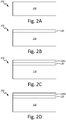
- FIGS. 2A-2D and FIG. 3 are embodiments of process 200 for applying a corrosion barrier system on a component.
- FIG. 2A shows component 100 including substrate 110 without a coating.
- Process 200 begins by applying conversion coat 120 onto the surfaces of substrate 110, resulting in the component shown in FIG. 2B , which includes substrate 110 and conversion coat 120.
- Conversion coat 120 is applied using, for example, spraying, dipping, or immersion bath techniques.
- ALD is used to deposit corrosion resistant layer 130 on top of conversion coat layer 120.
- ALD first deposits a single monolayer of a first ALD precursor adsorbed on the surfaces of the component, including internal surfaces deep within the core of the component, which may have complex internal geometries.
- ALD is a self-limiting process and deposits only a single monolayer of the first precursor. Any non-adsorbed first precursor is removed from the system, leaving behind the ALD intermediate coated component, which includes substrate 110, conversion coat layer 120, and ALD intermediate corrosion resistant layer.
- the first precursor gas can be, for example, a volatile organometallic aluminum such as trimethyl aluminum or aluminum trichloride.
- the first precursor gas can be, for example, a volatile titanium precursor such as TiCl 4 .
- the first precursor gas can be, for example, a volatile organometallic silicon.
- a second ALD precursor is added, which bonds only with the adsorbed first precursor in a self-limiting process. Any by-products or unreacted second precursor is removed from the system, leaving behind component 100 shown in FIG. 2C , including substrate 110, conversion coat 120, and corrosion resistant layer 130a.
- the second precursor gas can be, for example, plasma O 2 , H 2 O, and O 3 .
- the second precursor gas can be, for example, ammonia or plasma nitrogen.
- Corrosion resistant layer 130 can be a single mono-layer deposited by ALD as described herein, shown in FIG. 2C and designated 130a.
- corrosion resistant layer 130 can be more than one mono-layer deposited by ALD and is designated as 130n (n can be any integer greater than 1, bounded by the total thickness of corrosion resistant layer from 1 to 500 nm, inclusive).
- the ALD steps are repeated, forming a second mono-layer making up corrosion resistant layer 130n.
- the ALD steps can be repeated in an iterative manner until a desired thickness of corrosion resistant layer 130n is formed.
- FIG. 2D shows component 100 including substrate 110, conversion coat 120, and corrosion resistant layer 130n.
- Corrosion resistant layer 130 encapsulates the surfaces of component 100, which provides a uniform, pinhole-free coating deep into the core of component 100 and reduces corrosion in both neutral and acidic environments compared to a component without corrosion resistant layer 130 deposited by ALD.
- top coat 140 can be applied on top of corrosion resistant layer 130.
- FIG. 3 shows component 100 including substrate 110, conversion coat 120, corrosion resistant layer 130, and top coat 140, which provides additional corrosion protection to component 100.
- Top coat 140 protects component 100 from abrasive damage from dust or debris traveling at high velocities through or nearby component 100 compared to component 100 without top coat 140.
- FIGS. 4A-4C are comparative examples of coatings before and after exposure to a corrosive environment.
- FIG. 4A shows a series of fins within a heat exchanger coated with only a hexavalent chromium containing conversion coat (Permatreat® 686A) on an aluminum or aluminum alloy substrate.
- Permatreat® 686A a hexavalent chromium containing conversion coat
- brazed in fins formed of aluminum 3003 were sectioned and then coated so that the coating(s) would not be damaged by the cutting tools.
- Exposed samples were subjected to a 5% v/v sulfuric acid environment for 10 days at 25° C.
- FIG. 4B shows a series of fins within a heat exchanger coated with only a corrosion resistant layer (250 nm layer of Nb 2 O 5 deposited by ALD).
- Column X shows the coated fins before exposure to a corrosive environment and column Y shows a color change and flaking, indicating oxidative degradation of the aluminum substrate after exposure to the corrosive environment.
- FIG. 4B shows a series of fins within a heat exchanger coated with only a corrosion resistant layer (250 nm layer of Nb 2 O 5 deposited by ALD).
- FIG. 4C shows a series of fins within a heat exchanger coated with both, a conversion coat (Permatreat® 686A) and a corrosion resistant layer (250 nm layer of Nb 2 O 5 deposited by ALD).
- Column X shows the coated fins before exposure to a corrosive environment and column Y shows little to no color change and no indication of flaking, indicating oxidative protection of the aluminum substrate after exposure to the corrosive environment.
- FIGS. 5A-5C are comparative examples of coatings before and after exposure to a corrosive environment.
- FIG. 5A shows a series of fins within a heat exchanger coated with only a hexavalent chromium containing conversion coat (Permatreat® 686A) on an aluminum substrate.
- Column X shows the coated fins before exposure to a corrosive environment and column Y shows a dramatic color change indicating that the aluminum substrate is thoroughly oxidized after exposure to the corrosive environment.
- FIG. 5B shows a series of fins within a heat exchanger coated with only a corrosion resistant layer (500 nm layer of Nb 2 O 5 deposited by ALD).
- FIG. 5C shows a series of fins within a heat exchanger coated with both, a conversion coat (Permatreat® 686A) and a corrosion resistant layer (500 nm layer of Nb 2 O 5 deposited by ALD).
- Column X shows the coated fins before exposure to a corrosive environment and column Y shows little to no color change and no indication of flaking, indicating oxidative protection of the aluminum substrate after exposure to the corrosive environment.
- hexavalent chromium and non-hexavalent chromium conversion coats can enhance the bond strength between the corrosion resistant layer and the underlying substrate, it is also believed that other processes, such as sol-gel, boe-gel, and boehmite-like (steam generated oxide layer) processes can also enhance the bond strength between the corrosion resistant layer and the underlying substrate.
- a method of applying a heat exchanger coating system includes forming a conversion coated substrate by applying a conversion coat onto a substrate to provide corrosion resistance to the substrate and encapsulating the conversion coated substrate with a pinhole-free, uniform, atomic layer deposited, corrosion resistant coating.
- the method of the preceding paragraph can optionally include, additionally and/or alternatively, any one or more of the following features, configurations and/or additional components:
- the encapsulating the conversion coated substrate includes applying a first corrosion resistant coating layer by atomic layer deposition and applying a second corrosion resistant coating layer over the first corrosion resistant coating layer by atomic layer deposition.
- the conversion coat includes hexavalent chromium.
- the conversion coat includes non-hexavalent chromium selected from the group consisting of trivalent chromium, Mo, Mn, Zr, Ti, Ni, Zn, V, P, Co, La, Ce, rare earth metals, and combinations thereof.
- the conversion coat is an oxidation layer formed by a sol-gel, boe-gel, or boehmite process.
- the substrate is formed of aluminum or an aluminum alloy.
- the substrate is formed of stainless steel, Ti, Ni, Ti alloy, or Ni alloy.
- the method includes applying a topcoat over the corrosion resistant coating.
- the topcoat is formed of a phenolic epoxy or silicone.
- the corrosion resistant coating is formed from the group consisting of a metal oxide, metal nitride, semiconductor, phosphor, fluoride, and combinations thereof.
- a heat exchanger coating system includes a conversion coated substrate including a substrate and a conversion coat covering the substrate to provide corrosion resistance to the substrate, and a pinhole-free, uniform, atomic layer deposited, corrosion resistant coating encapsulating the conversion coated substrate.
- the heat exchanger of the preceding paragraph can optionally include, additionally and/or alternatively, any one or more of the following features, configurations and/or additional components:
- the conversion coat includes hexavalent chromium.
- the conversion coat includes non-hexavalent chromium selected from the group consisting of trivalent chromium, Mo, Mn, Zr, Ti, Ni, Zn, V, P, Co, La, Ce, rare earth metals, and combinations thereof.
- the conversion coat is an oxidation layer formed by a sol-gel, boe-gel, or boehmite process.
- the substrate is formed of aluminum or an aluminum alloy.
- the substrate is formed of stainless steel, Ti Ni, Ti alloy, or Ni alloy.
- the system includes a topcoat over the corrosion resistant coating.
- the corrosion resistant coating is formed from the group consisting of a metal oxide, metal nitride, semiconductor, phosphor, fluoride, and combinations thereof.
- the metal oxide is selected from the group consisting of Al 2 O 3 , TiO 2 , ZrO 2 , HfO 2 , Ta 2 O 5 , Nb 2 O 5 , Sc 2 O 3 , Y 2 O 3 , MgO, B 2 O 3 , SiO 2 , GeO 2 , La 2 O 3 , CeO 2 , PrO x , Nd 2 O 3 , Sm 2 O 3 , EuO x , Gd 2 O 3 , Dy 2 O 3 , Ho 2 O 3 , Er 2 O 3 , Tm 2 O 3 , Yb 2 O 3 , Lu 2 O 3 , SrTiO 3 , BaTiO 3 , PbTiO 3 , PbZrO 3 , BixTiyO, BixSiyO, SrTa 2 O 6 , SrBi 2 Ta 2 O 9 , YScO 3 , LaAlO 3 , NdAlO 3 , GdS
- the metal nitride is selected from the group consisting of BN, AlN, GaN, InN, Si 3 N 4 , Ta 3 N 5 , Cu 3 N, Zr 3 N 4 , Hf 3 N 4 , LaN, LuN, TiN, Ti-Si-N, Ti-Al-N, TaN, NbN, MoN, WN x , WN x C y , Co x N, Sn x N, and combinations thereof.
Landscapes
- Chemical & Material Sciences (AREA)
- Engineering & Computer Science (AREA)
- Mechanical Engineering (AREA)
- Metallurgy (AREA)
- Materials Engineering (AREA)
- Chemical Kinetics & Catalysis (AREA)
- Organic Chemistry (AREA)
- General Chemical & Material Sciences (AREA)
- Inorganic Chemistry (AREA)
- Physics & Mathematics (AREA)
- Thermal Sciences (AREA)
- General Engineering & Computer Science (AREA)
- Other Surface Treatments For Metallic Materials (AREA)
Abstract
A method (200) of applying a heat exchanger coating system includes forming a conversion coated substrate by applying a conversion coat (120) onto a substrate (110) to provide corrosion resistance to the substrate and encapsulating the conversion coated substrate with a pinhole-free, uniform, atomic layer deposited, corrosion resistant coating (130).
Description
- The present disclosure relates generally to heat exchangers. More specifically, this disclosure relates to corrosion barrier coatings of heat exchangers.
- Many components within an aircraft are coated with corrosion barriers to increase the useful life of the components by increasing the corrosion resistance of the components. There are various environmental insults that may be present in, for example, a gas turbine engine under load such as cyclic high temperatures. Some conventional corrosion barriers are able to partially mitigate the impact of corrosive environments within the aircraft. However, internal surfaces of some of these components may be non-line of sight and many conventional corrosion barrier systems are unable to coat the internal surfaces of components with complex internal geometries. Additionally, it is difficult to uniformly apply conventional corrosion barriers, leaving some areas inadequately covered and other areas thickened to the point of chipping off. These uncovered, inadequately covered, or chipped off areas are more prone to corrosion and degradation of the component at these sites, reducing the component's useful life.
- A method of applying a heat exchanger coating system includes forming a conversion coated substrate by applying a conversion coat onto a substrate to provide corrosion resistance to the substrate and encapsulating the conversion coated substrate with a pinhole-free, uniform, atomic layer deposited, corrosion resistant coating.
- A heat exchanger coating system includes a conversion coated substrate including a substrate and a conversion coat covering the substrate to provide corrosion resistance to the substrate, and a pinhole-free, uniform, atomic layer deposited, corrosion resistant coating encapsulating the conversion coated substrate.
-
-
FIG. 1A is a cross-sectional view of one embodiment of a component with a corrosion barrier system. -
FIG. 1B is a cross-sectional view of another embodiment of a component with a corrosion barrier system. -
FIGS. 2A-2D is one embodiment of a method for applying the corrosion barrier system on a component. -
FIG. 3 is another embodiment of a method for applying the corrosion barrier system on a component. -
FIGS. 4A-4C are comparative examples of coatings before and after exposure to a corrosive environment. -
FIGS. 5A-5C are another set of comparative examples of coatings before and after exposure to a corrosive environment. - Gas turbine engine corrosion is a common problem and can be linked to contaminants present in the air inlet systems, water systems, and fuel systems. For example, trace amounts of sulfur oxides and nitrogen oxides present in these systems can react with moisture in the air to create acidic environments within the gas turbine engine, including heat exchanger units. These acidic environments greatly increase the oxidation rate of metallic components within the engine if not properly protected. Even minor imperfections in a corrosion barrier system such as cracks and small holes in a coating can serve as nucleation sites for the onset of corrosion of the component.
- Heat exchangers are typically designed with complex internal geometries in order to maximize the transfer of heat between two mediums. As such, many heat exchangers include a torturous flow path, which makes it very difficult to apply a corrosion barrier system deep within the core of the heat exchanger using conventional coating techniques, such as dipping, immersion baths, and spraying. This leaves the uncoated or inadequately coated internal metallic surfaces within the heat exchanger prone to corrosive damage.
- Disclosed herein is a corrosion barrier system which extends the useful life of a component by increasing the component's resistance to corrosive environments within an aircraft. The disclosed corrosion barrier system results in a uniform pinhole-free coating that extends through non-line of sight passages and deep into the core of the component. Furthermore, the disclosed corrosion barrier system is more resistant to both neutral and acidic environments compared to conventional corrosion barrier systems.
-
FIG. 1A is a cross-sectional view of one embodiment of a component with a corrosion barrier system.FIG. 1A showscomponent 100 includingsubstrate 110,conversion coat 120, and corrosionresistant layer 130.Component 100 can be any component in need of corrosion protection within an aircraft such as, for example, heat exchangers, compressor sections, combustion sections, and turbine sections of a gas turbine engine. - In one embodiment,
substrate 110 is formed of aluminum or an aluminum alloy. Alternatively,substrate 110 can be formed of other metals such as stainless steel, titanium, nickel, titanium alloy, or a nickel alloy. The use of a particular metal or alloy can be optimized based on the particular micro-environment to which the component will be exposed. For example, a component within the combustion section of a gas turbine engine can experience very high cyclic temperatures, and a component formed of nickel or a nickel alloy can tolerate better the cyclic high temperatures within the combustion section compared to a component formed of aluminum or an aluminum alloy. In other words, a component within the combustion section formed of nickel or a nickel alloy will crack, warp, or break less frequently or to a lesser degree compared to a component formed of aluminum or an aluminum alloy within the same combustion section. -
Conversion coat 120 can be a non-rinse conversion coat containing hexavalent chromium such as, for example, Permatreat® 686A (Chemetall, Auckland, New Zealand) or BONDERITE® M-CR 600 AERO or BONDERITE® M-CR 1200 AERO (Henkel Corp., Dusseldorf, Germany). However, hexavalent chromium is a hazardous compound to work with and poses a significant environmental threat if not handled and disposed of properly. As such,conversion coat 120 can be a non-hexavalent chromium containing conversion coat, having ions selected from the group consisting of trivalent chromium, Mo, Mn, Zr, Ti, Ni, Zn, V, P, Co, La, Ce, rare earth metals, or combinations thereof. - Alternatively,
conversion coat 120 can contain trivalent chromium ions and then be exposed to an oxidizer such as, for example, hydrogen peroxide or permanganate. This process converts the trivalent chromium to a hexavalent chromium state, which can provide increased corrosion protection compared toconversion coat 120 containing only trivalent chromium ions. -
Conversion coat 120 can provide an active inhibition of corrosion should corrosionresistant coating 130 become compromised. Additionally,conversion coat 120 can increase the bond strength betweensubstrate 110 and corrosionresistant coating 130 compared to the bond strength betweensubstrate 110 and corrosionresistant coating 130 without a conversion coat. - Alternatively,
conversion coat 120 can be an oxidation layer formed by, for example, sol-gel, boe-gel, or boehmite-like (steam generated oxide layer) processes. The sol-gel process, for example, can entail a cleaning and de-oxidation step to remove any native oxides on the surface of the component followed by application of the sol-gel to create an oxidation layer. The resultant oxidation layer helps to prevent further oxidation ofunderlying substrate 110 while also promoting adhesion of subsequently added corrosionresistant layer 130. - Alternatively,
conversion coat 120 can entail additional pretreatment steps or different pretreatment steps whensubstrate 110 is formed of stainless steel, Ti, Ni, Ti alloy or Ni alloy. For example, a method such as AMS2700 using nitric acid, nitric acid and dichromate, or citric acid can be used to passivate stainless steel. The composition ofconversion coat 120 and method of application can be optimized based on the composition of theunderlying substrate 110 and the amount of corrosion protection needed in a particular location within a gas turbine engine. - Corrosion
resistant layer 130 is a uniform pinhole-free layer coveringconversion coat 120, including non-line of sight surfaces ofcomponent 100. For example, a heat exchanger with complex internal geometries will be uniformly coated with a pinhole-free layer deep within the core of the heat exchanger. - Corrosion
resistant layer 130 is applied using atomic layer deposition (ALD) and can be formed of any elements or compounds compatible with ALD. For example, corrosionresistant layer 130 can be selected from the group consisting of a metal oxide, metal nitride, semiconductor, phosphor, fluoride, or combinations thereof. - Metal oxides, for example, can be selected from the group consisting of Al2O3, TiO2, ZrO2, HfO2, Ta2O5, Nb2O5, Sc2O3, Y2O3, MgO, B2O3, SiO2, GeO2, La2O3, CeO2, PrOx, Nd2O3, Sm2O3, EuOx, Gd2O3, Dy2O3, Ho2O3, Er2O3, Tm2O3, Yb2O3, Lu2O3, SrTiO3, BaTiO3, PbTiO3, PbZrO3, BixTiyO, BixSiyO, SrTa2O6, SrBi2Ta2O9, YScO3, LaAlO3, NdAlO3, GdScO3, LaScO3, LaLuO3, LaYbO3, Er3Ga5O13, In2O3, In2O3:Sn, In2O3:F, In2O3:Zr, SnO2, SnO2:Sb, Sb2O3, ZnO, ZnO:Al, ZnO:B, ZnO:Ga, RuO2, RhO2, IrO2, Ga2O3, VO2, V2O5, WO3, W2O3, NiO, CuOx, FeOx, CrOx, CoOx, MnOx, LaCoO3, LaNiO3, LaMnO3, La1-xCaxMnO3, and combinations thereof.
- Metal nitrides, for example, can be selected from the group consisting of BN, AlN, GaN, InN, Si3N4, Ta3N5, Cu3N, Zr3N4, Hf3N4, LaN, LuN, TiN, Ti-Si-N, Ti-Al-N, TaN, NbN, MoN, WNx, WNxCy, CoxN, SnxN, and combinations thereof.
- Semiconductors, for example, can be selected from the group consisting of ZnS, ZnSe, ZnTe, CaS, SrS, BaS, CdS, CdTe, MnTe, GaAs, AlAs, AlP, InP, GaP, InAs, PbS, SnS, In2S3, Sb2S3, CuxS, CuGaS2, WS2, SiC, Ge2Sb2Te5 and combinations thereof.
- Phosphors, for example, can be selected from the group consisting of ZnS:M (M=Mn,Tb,Tm); CaS:M (M=Eu, Ce, Tb, Pb); SrS:M(M=Ce, Tb, Pb), or combinations thereof.
- Fluorides, for example, can be selected from the group consisting of CaF2, SrF2, MgF2, LaF3, ZnF2 and combinations thereof.
- Corrosion
resistant layer 130 can also be formed of elements or compounds, for example, selected from the group consisting of Ru, Pt, Ir, Pd, Rh, Ag, Cu, Ni, Co, Fe, Mn, Ta, W, Mo, Ti, Al, Si, Ge, La2S3, Y2O2S, TiCx, TiS2, TaCx, WCx, Ca3(PO4)2, CaCO3, and combinations thereof. - Corrosion
resistant layer 130 can be made up of one sub-layer deposited by ALD. Alternatively, corrosionresistant layer 130 can be made up of multiple sub-layers deposited by ALD in an iterative process described elsewhere herein. Each sub-layer can be formed of the same elements and compounds or each sub-layer can be formed of different elements and compounds. Each sub-layer typically has a thickness of 5 to 10 nanometers (0.0002 to 0.0004 mils). However, corrosionresistant layer 130 can have a total thickness of between 1 and 500 nanometers (0.00004 and 0.02 mils), inclusive. -
FIG. 1B is a cross-sectional view of another embodiment of a component with a corrosion barrier system.FIG. 1B showscomponent 100 includingsubstrate 110,conversion coat 120, corrosionresistant layer 130, andtop coat 140.Top coat 140 can be formed of, for example, silicone or a phenolic epoxy coating.Top coat 140 covers corrosionresistant layer 130 and is applied by spraying, painting, or bath immersion techniques and can have a thickness of 5-25 microns.Top coat 140 provides an additional layer of protection against environmental induced corrosion. -
FIGS. 2A-2D andFIG. 3 are embodiments ofprocess 200 for applying a corrosion barrier system on a component.FIG. 2A showscomponent 100 includingsubstrate 110 without a coating.Process 200 begins by applyingconversion coat 120 onto the surfaces ofsubstrate 110, resulting in the component shown inFIG. 2B , which includessubstrate 110 andconversion coat 120.Conversion coat 120 is applied using, for example, spraying, dipping, or immersion bath techniques. - Next, ALD is used to deposit corrosion
resistant layer 130 on top ofconversion coat layer 120. ALD first deposits a single monolayer of a first ALD precursor adsorbed on the surfaces of the component, including internal surfaces deep within the core of the component, which may have complex internal geometries. ALD is a self-limiting process and deposits only a single monolayer of the first precursor. Any non-adsorbed first precursor is removed from the system, leaving behind the ALD intermediate coated component, which includessubstrate 110,conversion coat layer 120, and ALD intermediate corrosion resistant layer. - For Al2O3, the first precursor gas can be, for example, a volatile organometallic aluminum such as trimethyl aluminum or aluminum trichloride. For TiO2, the first precursor gas can be, for example, a volatile titanium precursor such as TiCl4. For SiO2, the first precursor gas can be, for example, a volatile organometallic silicon.
- Next, a second ALD precursor is added, which bonds only with the adsorbed first precursor in a self-limiting process. Any by-products or unreacted second precursor is removed from the system, leaving behind
component 100 shown inFIG. 2C , includingsubstrate 110,conversion coat 120, and corrosion resistant layer 130a. For oxides, the second precursor gas can be, for example, plasma O2, H2O, and O3. For nitrides, the second precursor gas can be, for example, ammonia or plasma nitrogen. - Corrosion
resistant layer 130 can be a single mono-layer deposited by ALD as described herein, shown inFIG. 2C and designated 130a. Alternatively, corrosionresistant layer 130 can be more than one mono-layer deposited by ALD and is designated as 130n (n can be any integer greater than 1, bounded by the total thickness of corrosion resistant layer from 1 to 500 nm, inclusive). The ALD steps are repeated, forming a second mono-layer making up corrosion resistant layer 130n. The ALD steps can be repeated in an iterative manner until a desired thickness of corrosion resistant layer 130n is formed.FIG. 2D showscomponent 100 includingsubstrate 110,conversion coat 120, and corrosion resistant layer 130n. - Corrosion
resistant layer 130 encapsulates the surfaces ofcomponent 100, which provides a uniform, pinhole-free coating deep into the core ofcomponent 100 and reduces corrosion in both neutral and acidic environments compared to a component without corrosionresistant layer 130 deposited by ALD. - In another embodiment of
process 200,top coat 140 can be applied on top of corrosionresistant layer 130.FIG. 3 showscomponent 100 includingsubstrate 110,conversion coat 120, corrosionresistant layer 130, andtop coat 140, which provides additional corrosion protection tocomponent 100.Top coat 140 protectscomponent 100 from abrasive damage from dust or debris traveling at high velocities through ornearby component 100 compared tocomponent 100 withouttop coat 140. -
FIGS. 4A-4C are comparative examples of coatings before and after exposure to a corrosive environment.FIG. 4A shows a series of fins within a heat exchanger coated with only a hexavalent chromium containing conversion coat (Permatreat® 686A) on an aluminum or aluminum alloy substrate. For the set ofFIGS. 4A-4C and 5A-5C , brazed in fins formed of aluminum 3003 were sectioned and then coated so that the coating(s) would not be damaged by the cutting tools. Exposed samples were subjected to a 5% v/v sulfuric acid environment for 10 days at 25° C. - Column X shows the coated fins before exposure to the corrosive environment and column Y shows a dramatic color change indicating that the aluminum substrate is thoroughly oxidized after exposure to the corrosive environment.
FIG. 4B shows a series of fins within a heat exchanger coated with only a corrosion resistant layer (250 nm layer of Nb2O5 deposited by ALD). Column X shows the coated fins before exposure to a corrosive environment and column Y shows a color change and flaking, indicating oxidative degradation of the aluminum substrate after exposure to the corrosive environment.FIG. 4C shows a series of fins within a heat exchanger coated with both, a conversion coat (Permatreat® 686A) and a corrosion resistant layer (250 nm layer of Nb2O5 deposited by ALD). Column X shows the coated fins before exposure to a corrosive environment and column Y shows little to no color change and no indication of flaking, indicating oxidative protection of the aluminum substrate after exposure to the corrosive environment. -
FIGS. 5A-5C are comparative examples of coatings before and after exposure to a corrosive environment.FIG. 5A shows a series of fins within a heat exchanger coated with only a hexavalent chromium containing conversion coat (Permatreat® 686A) on an aluminum substrate. Column X shows the coated fins before exposure to a corrosive environment and column Y shows a dramatic color change indicating that the aluminum substrate is thoroughly oxidized after exposure to the corrosive environment.FIG. 5B shows a series of fins within a heat exchanger coated with only a corrosion resistant layer (500 nm layer of Nb2O5 deposited by ALD). Column X shows the coated fins before exposure to a corrosive environment and column Y shows a color change and flaking, indicating oxidative degradation of the aluminum substrate after exposure to the corrosive environment.FIG. 5C shows a series of fins within a heat exchanger coated with both, a conversion coat (Permatreat® 686A) and a corrosion resistant layer (500 nm layer of Nb2O5 deposited by ALD). Column X shows the coated fins before exposure to a corrosive environment and column Y shows little to no color change and no indication of flaking, indicating oxidative protection of the aluminum substrate after exposure to the corrosive environment. - Although not wanting to be limited by theory, it is believed that when only a corrosion resistant layer is applied, the corrosion resistant layer does not bond well to the underlying substrate and delaminates when stressed. Although hexavalent chromium and non-hexavalent chromium conversion coats can enhance the bond strength between the corrosion resistant layer and the underlying substrate, it is also believed that other processes, such as sol-gel, boe-gel, and boehmite-like (steam generated oxide layer) processes can also enhance the bond strength between the corrosion resistant layer and the underlying substrate.
- The following are non-exclusive descriptions of possible embodiments of the present invention.
- A method of applying a heat exchanger coating system includes forming a conversion coated substrate by applying a conversion coat onto a substrate to provide corrosion resistance to the substrate and encapsulating the conversion coated substrate with a pinhole-free, uniform, atomic layer deposited, corrosion resistant coating.
- The method of the preceding paragraph can optionally include, additionally and/or alternatively, any one or more of the following features, configurations and/or additional components:
- The encapsulating the conversion coated substrate includes applying a first corrosion resistant coating layer by atomic layer deposition and applying a second corrosion resistant coating layer over the first corrosion resistant coating layer by atomic layer deposition.
- The conversion coat includes hexavalent chromium.
- The conversion coat includes non-hexavalent chromium selected from the group consisting of trivalent chromium, Mo, Mn, Zr, Ti, Ni, Zn, V, P, Co, La, Ce, rare earth metals, and combinations thereof.
- The conversion coat is an oxidation layer formed by a sol-gel, boe-gel, or boehmite process.
- The substrate is formed of aluminum or an aluminum alloy.
- The substrate is formed of stainless steel, Ti, Ni, Ti alloy, or Ni alloy.
- The method includes applying a topcoat over the corrosion resistant coating.
- The topcoat is formed of a phenolic epoxy or silicone.
- The corrosion resistant coating is formed from the group consisting of a metal oxide, metal nitride, semiconductor, phosphor, fluoride, and combinations thereof.
- A heat exchanger coating system includes a conversion coated substrate including a substrate and a conversion coat covering the substrate to provide corrosion resistance to the substrate, and a pinhole-free, uniform, atomic layer deposited, corrosion resistant coating encapsulating the conversion coated substrate.
- The heat exchanger of the preceding paragraph can optionally include, additionally and/or alternatively, any one or more of the following features, configurations and/or additional components:
- The conversion coat includes hexavalent chromium.
- The conversion coat includes non-hexavalent chromium selected from the group consisting of trivalent chromium, Mo, Mn, Zr, Ti, Ni, Zn, V, P, Co, La, Ce, rare earth metals, and combinations thereof.
- The conversion coat is an oxidation layer formed by a sol-gel, boe-gel, or boehmite process.
- The substrate is formed of aluminum or an aluminum alloy.
- The substrate is formed of stainless steel, Ti Ni, Ti alloy, or Ni alloy.
- The system includes a topcoat over the corrosion resistant coating.
- The corrosion resistant coating is formed from the group consisting of a metal oxide, metal nitride, semiconductor, phosphor, fluoride, and combinations thereof.
- The metal oxide is selected from the group consisting of Al2O3, TiO2, ZrO2, HfO2, Ta2O5, Nb2O5, Sc2O3, Y2O3, MgO, B2O3, SiO2, GeO2, La2O3, CeO2, PrOx, Nd2O3, Sm2O3, EuOx, Gd2O3, Dy2O3, Ho2O3, Er2O3, Tm2O3, Yb2O3, Lu2O3, SrTiO3, BaTiO3, PbTiO3, PbZrO3, BixTiyO, BixSiyO, SrTa2O6, SrBi2Ta2O9, YScO3, LaAlO3, NdAlO3, GdScO3, LaScO3, LaLuO3, LaYbO3, Er3Ga5O13, In2O3, In2O3:Sn, In2O3:F, In2O3:Zr, SnO2, SnO2:Sb, Sb2O3, ZnO, ZnO:Al, ZnO:B, ZnO:Ga, RuO2, RhO2, IrO2, Ga2O3, VO2, V2O5, WO3, W2O3, NiO, CuOx, FeOx, CrOx, CoOx, MnOx, LaCoO3, LaNiO3, LaMnO3, La1-xCaxMnO3, and combinations thereof.
- The metal nitride is selected from the group consisting of BN, AlN, GaN, InN, Si3N4, Ta3N5, Cu3N, Zr3N4, Hf3N4, LaN, LuN, TiN, Ti-Si-N, Ti-Al-N, TaN, NbN, MoN, WNx, WNxCy, CoxN, SnxN, and combinations thereof.
- While the invention has been described with reference to an exemplary embodiment(s), it will be understood by those skilled in the art that various changes may be made and equivalents may be substituted for elements thereof without departing from the scope of the claims. In addition, many modifications may be made to adapt a particular situation or material to the teachings of the invention as defined by the claims without departing from the scope thereof. Therefore, it is intended that the invention not be limited to the particular embodiment(s) disclosed, but that the invention will include all embodiments falling within the scope of the appended claims.
Claims (15)
- A method (200) of applying a heat exchanger coating system, the method comprising:forming a conversion coated substrate by applying a conversion coat (120) onto a substrate (110) to provide corrosion resistance to the substrate; andencapsulating the conversion coated substrate with a pinhole-free, uniform, atomic layer deposited, corrosion resistant coating (130).
- The method of claim 1, wherein encapsulating the conversion coated substrate comprises applying a first corrosion resistant coating layer by atomic layer deposition and applying a second corrosion resistant coating layer over the first corrosion resistant coating layer by atomic layer deposition.
- The method of claim 1 or 2, wherein the conversion coat includes hexavalent chromium; or wherein the conversion coat includes non-hexavalent chromium selected from the group consisting of trivalent chromium, Mo, Mn, Zr, Ti, Ni, Zn, V, P, Co, La, Ce, rare earth metals, and combinations thereof.
- The method of any preceding claim, wherein the conversion coat is an oxidation layer formed by a sol-gel, boe-gel, or boehmite process.
- The method of any preceding claim, wherein the substrate is formed of aluminum or aluminum alloy; or wherein the substrate is formed of stainless steel, Ti, Ni, Ti alloy, or Ni alloy.
- The method of any preceding claim, further comprising:
applying a topcoat over the corrosion resistant coating, wherein the topcoat is formed of a phenolic epoxy or silicone. - The method of any preceding claim, wherein the corrosion resistant coating is formed from the group consisting of a metal oxide, metal nitride, semiconductor, phosphor, fluoride, and combinations thereof.
- A heat exchanger coating system comprising:a conversion coated substrate including a substrate (110) and a conversion coat (120) covering the substrate to provide corrosion resistance to the substrate; anda pinhole-free, uniform, atomic layer deposited, corrosion resistant coating encapsulating the conversion coated substrate (130).
- The system of claim 8, wherein the conversion coat includes hexavalent chromium; or wherein the conversion coat includes non-hexavalent chromium selected from the group consisting of trivalent chromium, Mo, Mn, Zr, Ti, Ni, Zn, V, P, Co, La, Ce, rare earth metals, and combinations thereof.
- The system of claim 8 or 9, wherein the conversion coat is an oxidation layer formed by a sol-gel, boe-gel, or boehmite process.
- The system of any of claims 8 to 10, wherein the substrate is formed of aluminum or aluminum alloy; or wherein the substrate is formed of stainless steel, Ti, Ni, Ti alloy, or Ni alloy.
- The system of any of claims 8 to 11 and further comprising:
a topcoat over the corrosion resistant coating; optionally wherein the topcoat is formed of a phenolic epoxy or silicone. - The system of any of claims 8 to 12, wherein the corrosion resistant coating is formed from the group consisting of a metal oxide, metal nitride, semiconductor, phosphor, fluoride, and combinations thereof.
- The system of claim 13, wherein the metal oxide is selected from the group consisting of Al2O3, TiO2, ZrO2, HfO2, Ta2O5, Nb2O5, Sc2O3, Y2O3, MgO, B2O3, SiO2, GeO2, La2O3, CeO2, PrOx, Nd2O3, Sm2O3, EuOx, Gd2O3, Dy2O3, Ho2O3, Er2O3, Tm2O3, Yb2O3, Lu2O3, SrTiO3, BaTiO3, PbTiO3, PbZrO3, BixTiyO, BixSiyO, SrTa2O6, SrBi2Ta2O9, YScO3, LaAlO3, NdAlO3, GdScO3, LaScO3, LaLuO3, LaYbO3, Er3Ga5O13, In2O3, In2O3:Sn, In2O3:F, In2O3:Zr, SnO2, SnO2:Sb, Sb2O3, ZnO, ZnO:Al, ZnO:B, ZnO:Ga, RuO2, RhO2, IrO2, Ga2O3, VO2, V2O5, WO3, W2O3, NiO, CuOx, FeOx, CrOx, CoOx, MnOx, LaCoO3, LaNiO3, LaMnO3, La1-xCaxMnO3, and combinations thereof.
- The system of claim 13 or 14, wherein the metal nitride is selected from the group consisting of BN, AlN, GaN, InN, Si3N4, Ta3N5, Cu3N, Zr3N4, Hf3N4, LaN, LuN, TiN, Ti-Si-N, Ti-Al-N, TaN, NbN, MoN, WNx, WNxCy, CoxN, SnxN, and combinations thereof.
Applications Claiming Priority (1)
| Application Number | Priority Date | Filing Date | Title |
|---|---|---|---|
| US16/523,283 US20210025662A1 (en) | 2019-07-26 | 2019-07-26 | Corrosion barriers for heat exchangers |
Publications (1)
| Publication Number | Publication Date |
|---|---|
| EP3770299A1 true EP3770299A1 (en) | 2021-01-27 |
Family
ID=68771390
Family Applications (1)
| Application Number | Title | Priority Date | Filing Date |
|---|---|---|---|
| EP19213361.9A Withdrawn EP3770299A1 (en) | 2019-07-26 | 2019-12-03 | Corrosion barriers for heat exchangers |
Country Status (2)
| Country | Link |
|---|---|
| US (1) | US20210025662A1 (en) |
| EP (1) | EP3770299A1 (en) |
Families Citing this family (3)
| Publication number | Priority date | Publication date | Assignee | Title |
|---|---|---|---|---|
| CN113182789A (en) * | 2021-05-10 | 2021-07-30 | 江苏通盛换热器有限公司 | Production process of train heat exchanger |
| US11572521B1 (en) | 2021-11-12 | 2023-02-07 | Hamilton Sundstrand Corporation | Corrosion resistant dry film lubricants |
| US12522922B2 (en) * | 2023-06-13 | 2026-01-13 | Rtx Corporation | Coating system and substrate with coating system |
Citations (3)
| Publication number | Priority date | Publication date | Assignee | Title |
|---|---|---|---|---|
| EP2938758A1 (en) * | 2012-12-31 | 2015-11-04 | University of Tartu | Method of preparing corrosion resistant coatings |
| CN108220961A (en) * | 2018-01-12 | 2018-06-29 | 清华大学 | A kind of compound hydrogen infiltration-resistant material of stainless base steel and preparation method thereof |
| EP3569732A1 (en) * | 2018-05-17 | 2019-11-20 | Hamilton Sundstrand Corporation | Corrosion barrier |
Family Cites Families (1)
| Publication number | Priority date | Publication date | Assignee | Title |
|---|---|---|---|---|
| JP6003778B2 (en) * | 2013-04-03 | 2016-10-05 | 株式会社デンソー | Manufacturing method of heat exchanger |
-
2019
- 2019-07-26 US US16/523,283 patent/US20210025662A1/en not_active Abandoned
- 2019-12-03 EP EP19213361.9A patent/EP3770299A1/en not_active Withdrawn
Patent Citations (3)
| Publication number | Priority date | Publication date | Assignee | Title |
|---|---|---|---|---|
| EP2938758A1 (en) * | 2012-12-31 | 2015-11-04 | University of Tartu | Method of preparing corrosion resistant coatings |
| CN108220961A (en) * | 2018-01-12 | 2018-06-29 | 清华大学 | A kind of compound hydrogen infiltration-resistant material of stainless base steel and preparation method thereof |
| EP3569732A1 (en) * | 2018-05-17 | 2019-11-20 | Hamilton Sundstrand Corporation | Corrosion barrier |
Also Published As
| Publication number | Publication date |
|---|---|
| US20210025662A1 (en) | 2021-01-28 |
Similar Documents
| Publication | Publication Date | Title |
|---|---|---|
| US20210025662A1 (en) | Corrosion barriers for heat exchangers | |
| US4639399A (en) | Nickel oxide, ceramic insulated, high temperature coating | |
| US5740515A (en) | Erosion/corrosion protective coating for high-temperature components | |
| US8062759B2 (en) | Thermal barrier coating systems including a rare earth aluminate layer for improved resistance to CMAS infiltration and coated articles | |
| EP3779471A1 (en) | Air data probe corrosion protection | |
| US7300702B2 (en) | Diffusion barrier coating for Si-based components | |
| EP3168323B1 (en) | Power plant component | |
| EP1522535A2 (en) | Environmental barrier coating | |
| US20090169752A1 (en) | Method for Improving Resistance to CMAS Infiltration | |
| US12071684B2 (en) | Air data probe corrosion protection | |
| CN108026625B (en) | Zn alloy coated steel material containing Mg | |
| EP2104749A2 (en) | Bond coat compositions and arrangements of same capable of self healing | |
| EP3808870A1 (en) | Low temperature atomic layer deposited topcoats for pretreated aluminum | |
| KR20210131150A (en) | Plasma resistance coating layer and forming method thereof | |
| WO2019209401A1 (en) | Protection of components from corrosion | |
| EP3443139A1 (en) | Coating by ald for suppressing metallic whiskers | |
| US20200087796A1 (en) | Corrosion barrier | |
| KR20230005364A (en) | Hot-dip Zn-Al-Mg coated steel | |
| US6929868B2 (en) | SRZ-susceptible superalloy article having a protective layer thereon | |
| KR20260027333A (en) | Hot-dip al-zn-si-mg coated steel sheet and production method therefor, surface-treated steel sheet and production method therefor, and painted steel sheet and production method therefor | |
| KR101789725B1 (en) | Alloy-coated steel sheet and method for manufacturing the same | |
| CN108291312B (en) | Hot-dip galvanized steel sheet and method for producing same | |
| JP3074873B2 (en) | Surface coated metal material for vacuum equipment | |
| EP2339051B1 (en) | Article having thermal barrier coating | |
| JP2001295075A (en) | Corrosion-resistant ceramic coating member on metal substrate, method of manufacturing the same, and component constituted by the member |
Legal Events
| Date | Code | Title | Description |
|---|---|---|---|
| PUAI | Public reference made under article 153(3) epc to a published international application that has entered the european phase |
Free format text: ORIGINAL CODE: 0009012 |
|
| STAA | Information on the status of an ep patent application or granted ep patent |
Free format text: STATUS: THE APPLICATION HAS BEEN PUBLISHED |
|
| AK | Designated contracting states |
Kind code of ref document: A1 Designated state(s): AL AT BE BG CH CY CZ DE DK EE ES FI FR GB GR HR HU IE IS IT LI LT LU LV MC MK MT NL NO PL PT RO RS SE SI SK SM TR |
|
| AX | Request for extension of the european patent |
Extension state: BA ME |
|
| STAA | Information on the status of an ep patent application or granted ep patent |
Free format text: STATUS: THE APPLICATION IS DEEMED TO BE WITHDRAWN |
|
| 18D | Application deemed to be withdrawn |
Effective date: 20210728 |