EP3770092A1 - Sheet loading device, sheet post-processing device provided therewith, and image forming system - Google Patents
Sheet loading device, sheet post-processing device provided therewith, and image forming system Download PDFInfo
- Publication number
- EP3770092A1 EP3770092A1 EP20186671.2A EP20186671A EP3770092A1 EP 3770092 A1 EP3770092 A1 EP 3770092A1 EP 20186671 A EP20186671 A EP 20186671A EP 3770092 A1 EP3770092 A1 EP 3770092A1
- Authority
- EP
- European Patent Office
- Prior art keywords
- sheet
- top surface
- loading tray
- detection sensor
- loading
- Prior art date
- Legal status (The legal status is an assumption and is not a legal conclusion. Google has not performed a legal analysis and makes no representation as to the accuracy of the status listed.)
- Granted
Links
Images








Classifications
-
- B—PERFORMING OPERATIONS; TRANSPORTING
- B65—CONVEYING; PACKING; STORING; HANDLING THIN OR FILAMENTARY MATERIAL
- B65H—HANDLING THIN OR FILAMENTARY MATERIAL, e.g. SHEETS, WEBS, CABLES
- B65H31/00—Pile receivers
- B65H31/04—Pile receivers with movable end support arranged to recede as pile accumulates
- B65H31/08—Pile receivers with movable end support arranged to recede as pile accumulates the articles being piled one above another
- B65H31/10—Pile receivers with movable end support arranged to recede as pile accumulates the articles being piled one above another and applied at the top of the pile
-
- B—PERFORMING OPERATIONS; TRANSPORTING
- B65—CONVEYING; PACKING; STORING; HANDLING THIN OR FILAMENTARY MATERIAL
- B65H—HANDLING THIN OR FILAMENTARY MATERIAL, e.g. SHEETS, WEBS, CABLES
- B65H29/00—Delivering or advancing articles from machines; Advancing articles to or into piles
- B65H29/12—Delivering or advancing articles from machines; Advancing articles to or into piles by means of the nip between two, or between two sets of, moving tapes or bands or rollers
- B65H29/14—Delivering or advancing articles from machines; Advancing articles to or into piles by means of the nip between two, or between two sets of, moving tapes or bands or rollers and introducing into a pile
-
- B—PERFORMING OPERATIONS; TRANSPORTING
- B65—CONVEYING; PACKING; STORING; HANDLING THIN OR FILAMENTARY MATERIAL
- B65H—HANDLING THIN OR FILAMENTARY MATERIAL, e.g. SHEETS, WEBS, CABLES
- B65H31/00—Pile receivers
-
- B—PERFORMING OPERATIONS; TRANSPORTING
- B65—CONVEYING; PACKING; STORING; HANDLING THIN OR FILAMENTARY MATERIAL
- B65H—HANDLING THIN OR FILAMENTARY MATERIAL, e.g. SHEETS, WEBS, CABLES
- B65H29/00—Delivering or advancing articles from machines; Advancing articles to or into piles
- B65H29/20—Delivering or advancing articles from machines; Advancing articles to or into piles by contact with rotating friction members, e.g. rollers, brushes, or cylinders
-
- B—PERFORMING OPERATIONS; TRANSPORTING
- B65—CONVEYING; PACKING; STORING; HANDLING THIN OR FILAMENTARY MATERIAL
- B65H—HANDLING THIN OR FILAMENTARY MATERIAL, e.g. SHEETS, WEBS, CABLES
- B65H29/00—Delivering or advancing articles from machines; Advancing articles to or into piles
- B65H29/38—Delivering or advancing articles from machines; Advancing articles to or into piles by movable piling or advancing arms, frames, plates, or like members with which the articles are maintained in face contact
- B65H29/40—Members rotated about an axis perpendicular to direction of article movement, e.g. star-wheels formed by S-shaped members
-
- B—PERFORMING OPERATIONS; TRANSPORTING
- B65—CONVEYING; PACKING; STORING; HANDLING THIN OR FILAMENTARY MATERIAL
- B65H—HANDLING THIN OR FILAMENTARY MATERIAL, e.g. SHEETS, WEBS, CABLES
- B65H29/00—Delivering or advancing articles from machines; Advancing articles to or into piles
- B65H29/48—Delivering or advancing articles from machines; Advancing articles to or into piles by tables arranged to be tilted to cause sliding of articles
-
- B—PERFORMING OPERATIONS; TRANSPORTING
- B65—CONVEYING; PACKING; STORING; HANDLING THIN OR FILAMENTARY MATERIAL
- B65H—HANDLING THIN OR FILAMENTARY MATERIAL, e.g. SHEETS, WEBS, CABLES
- B65H29/00—Delivering or advancing articles from machines; Advancing articles to or into piles
- B65H29/50—Piling apparatus of which the discharge point moves in accordance with the height to the pile
-
- B—PERFORMING OPERATIONS; TRANSPORTING
- B65—CONVEYING; PACKING; STORING; HANDLING THIN OR FILAMENTARY MATERIAL
- B65H—HANDLING THIN OR FILAMENTARY MATERIAL, e.g. SHEETS, WEBS, CABLES
- B65H31/00—Pile receivers
- B65H31/26—Auxiliary devices for retaining articles in the pile
-
- B—PERFORMING OPERATIONS; TRANSPORTING
- B65—CONVEYING; PACKING; STORING; HANDLING THIN OR FILAMENTARY MATERIAL
- B65H—HANDLING THIN OR FILAMENTARY MATERIAL, e.g. SHEETS, WEBS, CABLES
- B65H31/00—Pile receivers
- B65H31/34—Apparatus for squaring-up piled articles
- B65H31/36—Auxiliary devices for contacting each article with a front stop as it is piled
-
- B—PERFORMING OPERATIONS; TRANSPORTING
- B65—CONVEYING; PACKING; STORING; HANDLING THIN OR FILAMENTARY MATERIAL
- B65H—HANDLING THIN OR FILAMENTARY MATERIAL, e.g. SHEETS, WEBS, CABLES
- B65H43/00—Use of control, checking, or safety devices, e.g. automatic devices comprising an element for sensing a variable
-
- B—PERFORMING OPERATIONS; TRANSPORTING
- B65—CONVEYING; PACKING; STORING; HANDLING THIN OR FILAMENTARY MATERIAL
- B65H—HANDLING THIN OR FILAMENTARY MATERIAL, e.g. SHEETS, WEBS, CABLES
- B65H43/00—Use of control, checking, or safety devices, e.g. automatic devices comprising an element for sensing a variable
- B65H43/08—Photoelectric devices
-
- B—PERFORMING OPERATIONS; TRANSPORTING
- B65—CONVEYING; PACKING; STORING; HANDLING THIN OR FILAMENTARY MATERIAL
- B65H—HANDLING THIN OR FILAMENTARY MATERIAL, e.g. SHEETS, WEBS, CABLES
- B65H7/00—Controlling article feeding, separating, pile-advancing, or associated apparatus, to take account of incorrect feeding, absence of articles, or presence of faulty articles
- B65H7/02—Controlling article feeding, separating, pile-advancing, or associated apparatus, to take account of incorrect feeding, absence of articles, or presence of faulty articles by feelers or detectors
- B65H7/14—Controlling article feeding, separating, pile-advancing, or associated apparatus, to take account of incorrect feeding, absence of articles, or presence of faulty articles by feelers or detectors by photoelectric feelers or detectors
-
- G—PHYSICS
- G03—PHOTOGRAPHY; CINEMATOGRAPHY; ANALOGOUS TECHNIQUES USING WAVES OTHER THAN OPTICAL WAVES; ELECTROGRAPHY; HOLOGRAPHY
- G03G—ELECTROGRAPHY; ELECTROPHOTOGRAPHY; MAGNETOGRAPHY
- G03G15/00—Apparatus for electrographic processes using a charge pattern
- G03G15/65—Apparatus which relate to the handling of copy material
- G03G15/6538—Devices for collating sheet copy material, e.g. sorters, control, copies in staples form
-
- G—PHYSICS
- G03—PHOTOGRAPHY; CINEMATOGRAPHY; ANALOGOUS TECHNIQUES USING WAVES OTHER THAN OPTICAL WAVES; ELECTROGRAPHY; HOLOGRAPHY
- G03G—ELECTROGRAPHY; ELECTROPHOTOGRAPHY; MAGNETOGRAPHY
- G03G15/00—Apparatus for electrographic processes using a charge pattern
- G03G15/65—Apparatus which relate to the handling of copy material
- G03G15/6538—Devices for collating sheet copy material, e.g. sorters, control, copies in staples form
- G03G15/6541—Binding sets of sheets, e.g. by stapling, glueing
-
- B—PERFORMING OPERATIONS; TRANSPORTING
- B65—CONVEYING; PACKING; STORING; HANDLING THIN OR FILAMENTARY MATERIAL
- B65H—HANDLING THIN OR FILAMENTARY MATERIAL, e.g. SHEETS, WEBS, CABLES
- B65H2404/00—Parts for transporting or guiding the handled material
- B65H2404/10—Rollers
- B65H2404/11—Details of cross-section or profile
- B65H2404/111—Details of cross-section or profile shape
- B65H2404/1114—Paddle wheel
-
- B—PERFORMING OPERATIONS; TRANSPORTING
- B65—CONVEYING; PACKING; STORING; HANDLING THIN OR FILAMENTARY MATERIAL
- B65H—HANDLING THIN OR FILAMENTARY MATERIAL, e.g. SHEETS, WEBS, CABLES
- B65H2405/00—Parts for holding the handled material
- B65H2405/10—Cassettes, holders, bins, decks, trays, supports or magazines for sheets stacked substantially horizontally
- B65H2405/11—Parts and details thereof
- B65H2405/111—Bottom
- B65H2405/1115—Bottom with surface inclined, e.g. in width-wise direction
- B65H2405/11151—Bottom with surface inclined, e.g. in width-wise direction with surface inclined upwardly in transport direction
-
- B—PERFORMING OPERATIONS; TRANSPORTING
- B65—CONVEYING; PACKING; STORING; HANDLING THIN OR FILAMENTARY MATERIAL
- B65H—HANDLING THIN OR FILAMENTARY MATERIAL, e.g. SHEETS, WEBS, CABLES
- B65H2801/00—Application field
- B65H2801/03—Image reproduction devices
- B65H2801/06—Office-type machines, e.g. photocopiers
Definitions
- the present disclosure relates to a sheet loading device on which a sheet such as a paper sheet is loaded after an image is formed thereon by an image forming apparatus such as a copier, a facsimile machine, a printer, or the like, a sheet post-processing device provided therewith, and an image forming system provided therewith.
- an image forming apparatus such as a copier, a facsimile machine, a printer, or the like
- a sheet post-processing device provided therewith
- an image forming system provided therewith.
- Sheet post-processing devices have conventionally been used which are capable of stacking a plurality of sheets (paper sheets) on which images have been formed by an image forming apparatus such as a copier, a printer, or the like, and performing post-processing such as stapling processing of binding the stacked sheets as a sheet bundle with a staple, punching processing of forming a hole (punched hole) using a punching device, etc.
- Such conventional sheet post-processing devices each include a sheet loading device having a discharge roller pair which discharges a sheet having undergone post-processing and a loading tray on which the sheet discharged by the discharge roller pair is loaded.
- a known example of a sheet loading device includes a paddle member which slaps an upstream part (a rear end part) of a sheet in a discharge direction after the sheet passes through a nip portion of a discharge roller pair, and thereby makes the sheet fall onto the loading tray.
- a sheet discharge device which is provided with a holding member rotatable about a rotation shaft arranged below a rotation shaft of a sheet discharge roller (a discharge roller pair).
- the holding member and the sheet discharge roller are respectively driven to rotate by a holding-member drive motor and a sheet-discharge drive motor, which are separate from each other.
- the holding member is caused to rotate by a driving force received from the holding-member drive motor, and thereby holds a rear end part of a sheet in a sheet discharge direction as if by slapping the rear end part from above.
- Another sheet discharge device which is provided with a scraping member; the scraping member is arranged coaxial with a driven discharge roller of a discharge rotary body pair (a discharge roller pair), and is driven to rotate by a sheet discharged by the discharge rotary body pair.
- the scraping member has a plurality of flexible blade members projecting from its outer peripheral surface. The blade members scrape a rear end part of a sheet having passed through the discharge rotary body pair, and further hold down the rear end part of the sheet loaded on a loading tray.
- An object of the present disclosure is to provide a sheet loading device capable of avoiding contact between a paddle member which slaps a rear end of a sheet down and a sheet on a loading tray, a post-processing device provided therewith, and an image forming system.
- a sheet loading device includes a discharge roller pair, a loading tray, a paddle member, a sheet holding member, a tray lifting-lowering drive portion, a top surface detection sensor, and a control portion.
- the discharge roller pair includes a drive roller and a driven roller which follows the drive roller to rotate, and discharges a sheet.
- the loading tray is arranged on a downstream side of the discharge roller pair with respect to a discharge direction of the sheet, and the sheet discharged by the discharge roller pair is loaded on the loading tray.
- the paddle member is arranged coaxial with the drive roller, and rotates in a same direction as the drive roller to thereby come into contact, from above, with an upstream part, in the discharge direction, of the sheet discharged by the discharge roller pair.
- the sheet holding member is arranged below the discharge roller pair, and is swingable between a holding position at which the sheet holding member holds the upstream part of the sheet in the discharge direction loaded on the loading tray and a retraction position at which the sheet holding member releases holding of the sheet.
- the tray lifting-lowering drive portion lifts and lowers the loading tray.
- the top surface detection sensor switches between an on state in which the top surface detection sensor performs detection of a sheet loading surface of the loading tray or of a top surface of the sheet loaded on the sheet loading surface and an off state in which the top surface detection sensor does not perform the detection.
- the control portion controls the tray lifting-lowering drive portion.
- the control portion is capable of performing a lifting-lowering operation to arrange the loading tray at a reference position by lowering the loading tray with the sheet holding member arranged at the holding position to turn the top surface detection sensor into the off state, then lifting the loading tray to turn the top surface detection sensor into the on state, and then lowering the loading tray again to turn the top surface detection sensor into the off state and stop the loading tray.
- a predetermined clearance is provided between the top surface of the sheet loaded on the loading tray and a rotational orbit of the paddle member.
- FIG. 1 is a schematic diagram of an image forming system S which includes an image forming apparatus 200 and a sheet post-processing device 5 according to an embodiment of the present disclosure.
- the image forming system S includes the image forming apparatus 200 and the sheet post-processing device 5.
- the image forming apparatus 200 is what is called a monochrome multifunction peripheral having functions of, for example, printing (print), scanning (image reading), and facsimile transmission.
- a document transport portion 203 is placed on a top surface of a main body portion 201.
- an image reading portion 204 is provided at a position that is below the document transport portion 203 but is inside the main body portion 201.
- the image reading portion 204 reads an image on a document loaded on the document transport portion 203 or an image on a document placed on an unillustrated contact glass provided on a top surface of the image reading portion 204.
- the image forming apparatus 200 further includes a sheet feeding portion 205, a sheet transport portion 206, an exposure portion 207, an image forming portion 208, a transfer portion 209, a fixing portion 210, a sheet discharge portion 211, a relay portion 212, and a main body control portion 213.
- the sheet feeding portion 205 holds a plurality of sheets P, and feeds them out one by one, separately from each other, during printing.
- the sheet transport portion 206 transports a sheet P fed out from the sheet feeding portion 205 to the transfer portion 209 and the fixing portion 210, and further transports the sheet P having undergone fixing to the sheet discharge portion 211 or to the relay portion 212.
- the exposure portion 207 emits laser light controlled based on image data toward the image forming portion 208.
- the image forming portion 208 includes a photosensitive drum 2081 as an image carrier and a development device 2082.
- the laser light emitted from the exposure portion 207 forms, on a surface of the photosensitive drum 2081, an electrostatic latent image based on a document image.
- the development device 2082 supplies toner to the electrostatic latent image to develop it into a toner image.
- the transfer portion 209 transfers, onto a sheet P, the toner image formed by the image forming portion 208 on the surface of the photosensitive drum 2081.
- the fixing portion 210 applies heat and pressure to the sheet P having the toner image transferred thereon to fix the toner image on the sheet P.
- the sheet P is transported to the sheet discharge portion 211 or to the relay portion 212.
- the sheet discharge portion 211 is arranged below the image reading portion 204.
- the sheet discharge portion 211 has an opening in its front face, and the sheet P after the printing (a printed sheet) is taken out from the front-face side.
- the relay portion 212 is arranged below the sheet discharge portion 211.
- the relay portion 212 has its downstream end in a sheet transport direction connected to the sheet post-processing device 5.
- the sheet P (printed matter) after the printing having been sent to the relay portion 212 passes through the relay portion 212 to be transported into the sheet post-processing device 5.
- the main body control portion 213 includes a CPU, an image processing portion, and a storage portion, of which none is illustrated, and other unillustrated electronic circuits and components.
- the CPU based on a control program and control data stored in the storage portion, controls operations of various constituent elements provided in the image forming apparatus 200 to perform processing related to functions of the image forming apparatus 200.
- the sheet feeding portion 205, the sheet transport portion 206, the exposure portion 207, the image forming portion 208, the transfer portion 209, and the fixing portion 210 each individually receive an instruction from the main body control portion 213, and coordinate with each other to perform printing with respect to the sheet P.
- the storage portion is configured as a combination of non-volatile storage devices such as a program ROM (Read Only Memory) and a data ROM and a volatile storage device such as a RAM (Random Access Memory).
- the sheet post-processing device 5 is attachably and detachably connected to a side face of the image forming apparatus 200.
- the sheet post-processing device 5 includes a post-processing housing 50, and a post-processing mechanism 6, a sheet transport mechanism 7, a processing tray 8, a sheet loading device 10, and a post-processing control portion 100, which are arranged inside the post-processing housing 50.
- a sheet receiving port 41 is provided in such a side face of the post-processing housing 50 as faces the image forming apparatus 200. After passing through the relay portion 212, the sheet P passes through the sheet receiving port 41 to be transported into the sheet post-processing device 5.
- a sheet transport path 42 extends from the sheet receiving port 41, in a direction away from the image forming apparatus 200 (leftward in FIG. 1 ), to a position above the processing tray 8.
- the post-processing mechanism 6 performs predetermined post-processing with respect to the sheet P transported along the sheet transport path 42.
- the post-processing mechanism 6 includes a punching processing portion 61 and a staple processing portion 62.
- the punching processing portion 61 is arranged at an intermediate position between the sheet receiving port 41, which is an upstream end of the sheet transport path 42 in the sheet transport direction (an arrow-Hl 1 direction in FIG. 2 ), and a downstream end of the sheet transport path 42.
- the punching processing portion 61 performs punching processing with respect to the sheet P transported along the sheet transport path 42 to form a punched hole (a binding hole) in the sheet P.
- the punched hole is formed along one of opposite edges of the sheet P in its width direction which is perpendicular to the sheet transport direction.
- the staple processing portion 62 is arranged at a position that is below the sheet transport path 42 but is on an upstream side of the processing tray 8 in the sheet transport direction.
- the sheet post-processing device 5 by using the staple processing portion 62, can perform staple processing (binding processing) of binding a bundle of sheets P (hereinafter referred to simply as "sheet bundle") placed on the processing tray 8 with a staple needle to bind the sheet bundle.
- sheet bundle a bundle of sheets P
- edge binding processing is performed, in which a sheet bundle is bound with a staple needle at a corner or at an edge.
- the sheet transport mechanism 7 transports the sheet P in the sheet transport direction which is along the sheet transport path 42.
- the sheet transport mechanism 7 has a transport roller pair 71 (see FIG. 2 ), an intermediate roller pair 72, and a discharge roller pair 73, which are arranged in this order from an upstream side in the sheet transport direction.
- the processing tray 8 is arranged below a downstream part of the sheet transport path 42 in a sheet discharge direction. In other words, the processing tray 8 is located at a position that is on a downstream side of the intermediate roller pair 72 in the sheet discharge direction but is below the intermediate roller pair 72. A plurality of sheets P having passed through the sheet transport path 42 to reach the processing tray 8 are placed on the processing tray 8, where the staple processing is performed on them by the staple processing portion 62.
- the sheet loading device 10 has a loading tray 11 arranged on a downstream side of the processing tray 8 in the sheet discharge direction to be adjacent to the processing tray 8.
- the sheet bundle, with respect to which the staple processing has been completed on the processing tray 8, is discharged by the discharge roller pair 73 to be loaded on the loading tray 11.
- the staple processing portion 62 does not perform the staple processing, the sheets P are transported to the loading tray 11 without being loaded on the processing tray 8.
- a detailed configuration of the sheet loading device 10 will be described later.
- the post-processing control portion 100 includes a CPU and a storage portion, of which neither is illustrated, and other unillustrated electronic circuits and components.
- the post-processing control portion 100 is communicably connected to the main body control portion 213.
- the post-processing control portion 100 receives an instruction from the main body control portion 213, and, by using the CPU, based on a control program and control data stored in the storage portion, controls operations of various constituent elements provided in the sheet post-processing device 5 to perform processing related to functions of the sheet post-processing device 5.
- the post-processing mechanism 6, the sheet transport mechanism 7, the processing tray 8, and the sheet loading device 10 each individually receive an instruction from the post-processing control portion 100, and coordinate with each other to perform the post-processing with respect to the sheet P.
- the storage portion is configured as a combination of storage devices such as a program ROM, a data ROM, a RAM, etc., of which none is illustrated. A detailed control path in the post-processing control portion 100 will be described later.
- FIG. 2 is a side sectional view showing an internal structure of the sheet post-processing device 5.
- FIG. 3 is a side sectional view showing a structure of and around the processing tray 8 shown in FIG. 2 .
- the transport roller pair 71 is arranged on a downstream side of the punching processing portion 61 in the sheet transport direction (the arrow-Hll direction) to be adjacent to the punching processing portion 61.
- the transport roller pair 71 transports a sheet that has undergone the punching processing or a sheet that has not undergone the punching processing to a downstream side in the sheet transport direction HI 1.
- the intermediate roller pair 72 is arranged, on the sheet transport path 42, at a position between an upstream-side end part and a downstream-side end part of the sheet transport path 42 in the sheet transport direction.
- the intermediate roller pair 72 includes a first drive roller 721 which rotates on receiving a driving force from a transport drive portion 70 (see FIG. 12 ), and a first driven roller 722 which follows the first drive roller 721 to rotate.
- the first drive roller 721 and the first driven roller 722 are in contact with each other under a predetermined nip pressure therebetween to form a first nip portion 72N which nips and transports a sheet.
- the first sheet detection portion S1 is a sensor which optically detects a sheet, and detects that a leading end of a sheet transported by the transport roller pair 71 has entered into the intermediate roller pair 72.
- the first sheet detection portion S1 also detects that the sheet transported by the intermediate roller pair 72 has passed through the intermediate roller pair 72.
- the discharge roller pair 73 is arranged on a downstream side of the sheet transport path 42 in the sheet transport direction.
- the discharge roller pair 73 includes a second drive roller 731 which rotates on receiving a driving force from a discharge drive portion 90 (see FIG. 12 ), and a second driven roller 732 which follows the second drive roller 731 to rotate.
- the second drive roller 731 and the second driven roller 732 are in contact with each other under a predetermined nip pressure therebetween to form a second nip portion 73N which nips and transports a sheet.
- the second nip portion 73N is released by a nip release mechanism 74 (see FIG. 12 ) when the staple processing portion 62 performs the staple processing.
- the second sheet detection portion S2 includes an actuator and a photosensor; the actuator has a contact piece, which a sheet discharged by the discharge roller pair 73 comes into contact with, and a detection piece, and the photosensor has a light emitter and a light receiver which are arranged facing each other with the detection piece located therebetween.
- the actuator rotationally moves in a clockwise direction, so that the detection piece moves out of an optical path extending from the light emitter to the light receiver.
- the processing tray 8 Below the sheet transport path 42, the processing tray 8 is arranged.
- a sheet bundle loaded on the processing tray 8 is subjected to the staple processing performed by the staple processing portion 62.
- the processing tray 8 is provided with a bundle discharge member 81 which supports an upstream-side end part (a rear end) of a sheet bundle.
- the bundle discharge member 81 is fixed to a drive belt (not shown) arranged on a rear-surface side of the processing tray 8, and part of the bundle discharge member 81 projects from a placing surface of the processing tray 8 in an L-shape in side view.
- the bundle discharge member 81 reciprocates along the placing surface of the processing tray 8 in the sheet transport direction.
- a sheet bundle loaded on the processing tray 8 and having been subjected to the staple processing by the staple processing portion 62 is discharged to the sheet loading device 10 by the discharge roller pair 73 with the second nip portion 73N recovered or by the bundle discharge member 81.
- the sheet loading device 10 has loaded thereon sheets having been subjected to the post-processing by the post-processing mechanism 6.
- the sheet loading device 10 includes the loading tray 11, a pair of cursor members 12, a projection member 13, a sheet holding member 14, and a paddle member 15.
- the loading tray 11 is arranged on a downstream side of the discharge roller pair 73 with respect to the sheet transport direction (hereinafter may also be referred to as the sheet discharge direction), and is a final destination to which a sheet is discharged in the sheet post-processing device 5.
- the loading tray 11 has a sheet loading surface 11a on which are loaded sheets discharged by the discharge roller pair 73 or by the bundle discharge member 81, such as sheets having been subjected to the punching processing by the punching processing portion 61, a sheet bundle having been subjected to the staple processing by the staple processing portion 62, etc.
- the sheet loading surface 11a is highest at its downstream-end part in the sheet discharge direction, and is inclined downward toward its upstream-side end part.
- the upstream-side end part of the sheet loading surface 11a is located below the discharge roller pair 73. Immediately near the sheet loading surface 11a on its upstream side, a sheet receiving wall 11b is provided upright. The sheet receiving wall 11b receives the upstream-side end part (the rear end) of a sheet that comes sliding down the sheet loading surface 11a.
- the loading tray 11 is configured to be able to be lifted and lowered by a tray lifting-lowering drive portion 113 (see FIG. 12 ) in accordance with an amount of sheets loaded on the sheet loading surface 11a.
- a top surface detection sensor S3 is arranged at a position that is slightly downstream of the upstream-side end part of the loading tray 11.
- the top surface detection sensor S3 is a photosensor that detects the sheet loading surface 11a or a top surface of a sheet loaded on the sheet loading surface 11a. In accordance with a detection signal of the top surface detection sensor S3, an operation of lifting-lowering (positioning) the loading tray 11 performed by the tray lifting-lowering drive portion 113 is controlled.
- the operation of lifting-lowering the loading tray 11 is performed once for every predetermined number of sheets (for example, every 10 sheets) or at predetermined time intervals (for example, every several seconds). Thereby, a position of a topmost surface of sheets on the sheet loading surface 11a is maintained at a constant height.
- a lower limit detection sensor S4 is provided which detects a lower limit position of the loading tray 11.
- the lower limit detection sensor S4 is a photosensor similar to the top surface detection sensor S3, and can detect, when an optical path of a detection portion is blocked by a flag 11c provided on and projecting from the loading tray 11, that the loading tray 11 has descended to the lower limit position.
- other sensors may be used instead of photosensors. Details of the operation of lifting-lowering the loading tray 11 will be described later.
- the pair of cursor members 12 are supported by a holder 121 through which a shaft 122 is inserted.
- the shaft 122 is supported by the post-processing housing 50 so as to extend along a sheet width direction above the discharge roller pair 73.
- the holder 121 is supported by the shaft 122 so as to be movable along the sheet width direction.
- the holder 121 supports the pair of cursor members 12 such that leading end parts of the pair of cursor members 12 are swingable in an up-down direction.
- the projection member 13 is a rod-shaped member having a predetermined width in the sheet width direction and extending in the sheet discharge direction in an arc shape, and is arranged below a sheet discharge port 2.
- the projection member 13 is arranged below the processing tray 8 so as to be below a discharge path via which a sheet is discharged from the discharge roller pair 73 along the processing tray 8.
- the projection member 13 is arranged, for example, at each of two positions in the sheet width direction, the two positions each being at a predetermined distance from a center part of the loading tray 11 in the sheet width direction.
- the projection members 13 are arranged at positions different from the position of the paddle member 15 with respect to the sheet width direction.
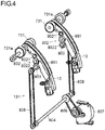
- the projection member 13 is supported by a projection drive portion 131 shown in FIGS. 4 and 5 , and displaced by the projection drive portion 131 along the sheet discharge direction.
- the projection drive portion 131 includes a guide rail 801, a drive transmission gear group 802, a drive transmission shaft 803, a drive shaft 804, a drive transmission belt 805, a drive belt 806, and a drive motor 807.
- Two guide rails 801, two drive transmission gear groups 802, two drive transmission shafts 803, and two drive transmission belts 805 are provided corresponding to the two projection members 13.
- One drive shaft 804, one drive belt 806, and one drive motor 807 are provided.
- the guide rail 801 is arranged on an upstream side of the discharge roller pair 73 in the sheet discharge direction.
- the guide rail 801 is an open-topped gutter-shaped member, extending in an arc shape in the sheet discharge direction like the projection member 13.
- the guide rail 801 accommodates and supports the projection member 13 inside thereof.
- the drive transmission gear group 802 is arranged below the guide rail 801.
- the drive transmission gear group 802 is composed of a plurality of gears in mesh with each other, and includes a pinion gear 8021 at an end on a side of the guide rail 801, and a drive transmission gear 8022 at an end on a side of the drive transmission shaft 803.
- the pinion gear 8021 is arranged directly under the guide rail 801. On a lower-face side of the projection member 13, there is formed a rack (not shown) of a rack-and-pinion gear mechanism.
- the rack has a plurality of teeth aligned along the sheet discharge direction.
- the pinion gear 8021 meshes with the rack of the projection member 13.
- an unillustrated window portion via which the pinion gear 8021 and the projection member 13 mesh with each other.
- the drive transmission shaft 803 is arranged in a lower part of the drive transmission gear group 802.
- the drive transmission shaft 803 extends along the sheet width direction.
- the drive transmission gear 8022 of the drive transmission gear group 802 is arranged coaxially with the drive transmission shaft 803, and rotates together with the drive transmission shaft 803.
- the drive shaft 804 is arranged below the drive transmission shaft 803.
- the drive shaft 804 extends along the sheet width direction.
- the drive transmission belt 805 is wound around the drive transmission shaft 803 and the drive shaft 804 via pulleys.
- the two drive transmission belts 805 are wound around the one drive shaft 804, and are respectively wound around the separate drive transmission shafts 803.
- the drive transmission belts 805 transmits a rotational force of the drive shaft 804 to the drive transmission shafts 803.
- the drive belt 806 is wound around the drive shaft 804 and a rotation shaft of the drive motor 807 via pulleys.
- the drive belt 806 is rotated by the drive motor 807.
- the projection drive portion 131 when the drive motor 807 rotates, a rotational force of the drive motor 807 is transmitted via the drive belt 806 to the drive shaft 804, so that the drive shaft 804 rotates.
- the rotational force is transmitted via the drive transmission belt 805 to the drive transmission shaft 803.
- the drive transmission shaft 803 rotates, the rotational force is transmitted via the drive transmission gear group 802 to the pinion gear 8021.
- the displacement of the projection members 13, in other words, the operation of the projection drive portion 131, is controlled by the post-processing control portion 100.
- the sheet holding member 14 is arranged on an upstream side of the loading tray 11 in the sheet discharge direction.
- the sheet holding member 14 is arranged below a rotation shaft 731a of the second drive roller 731 of the discharge roller pair 73.
- the sheet holding member 14 for example, two sheet holding members 14 are arranged to be spaced from each other by a predetermined distance on the loading tray 11 in the sheet width direction.
- the sheet holding members 14 are arranged at positions different from the position of the paddle member 15 with respect to the sheet width direction.
- the sheet holding member 14 is a rod-shaped member having a predetermined width in the sheet width direction and extending substantially in the up-down direction.
- the sheet holding member 14 is, at its lower end part, swingably supported about a swing shaft 14a which extends along the sheet width direction as a swing fulcrum.
- the sheet holding member 14 is caused by a sheet holding drive portion 142 (see FIG. 12 ) to swing about the swing shaft 14a in the sheet discharge direction, with its upper end part as a free end.
- the sheet holding member 14 is displaced between a holding position (see FIG. 14 ) for holding the upstream part of a sheet loaded on the loading tray 11 in the sheet discharge direction and a retraction position (see FIG. 3 ) for releasing the holding of the sheet.
- the sheet holding member 14 is, as shown in FIG. 3 , before a sheet discharging operation is started, stationary at the retraction position where it does not project toward the loading tray 11. In this manner, the sheet holding member 14, when out of use, does not interfere with discharging of a sheet.
- the paddle member 15 is rotated, and, before the paddle member 15 passes an upstream end of the loading tray 11 in the sheet discharge direction, swinging of the sheet holding member 14 is started. Then, the sheet holding member 14 is, as shown in FIG. 14 , displaced to the sheet-holding position where it holds the upstream part of a sheet loaded on the loading tray 11 in the sheet discharge direction.
- the paddle member 15 is arranged coaxially with the discharge roller pair 73.
- the paddle member 15 is arranged coaxially with the rotation shaft 731a of the second drive roller 731 extending along the sheet width direction.
- two paddle members 15 are provided coaxially with the rotation shaft 731a of each of the two second drive rollers 731, such that a total of four paddle members 15 are provided.
- FIG. 6 is a perspective view showing a configuration of the discharge drive portion 90 and a paddle drive portion 161 in the sheet loading device 10.
- the two second drive rollers 731 are simultaneously driven to rotate by the discharge drive portion 90.
- the discharge drive portion 90 includes a drive transmission shaft 301, a first drive transmission belt 302, a drive shaft 303, a second drive transmission belt 304, a drive transmission gear 305, a drive gear 306, and a drive motor 307.
- Two drive transmission shafts 301, two first drive transmission belts 302, and two second drive transmission belts 304 are provided corresponding to the two rotation shafts 731a of the two second drive rollers 731.
- One drive shaft 303, one drive transmission gear 305, one drive gear 306, and one drive motor 307 are provided.
- the drive transmission shaft 301 is arranged below the rotation shaft 731a of the second drive roller 731.
- the drive transmission shaft 301 extends along the sheet width direction.
- the first drive transmission belt 302 is wound around the rotation shaft 731a of the second drive roller 731 and the drive transmission shaft 301 via pulleys.
- the first drive transmission belt 302 transmits a rotational force of the drive transmission shaft 301 to the rotation shaft 731a.
- the drive shaft 303 is arranged below the drive transmission shaft 301.
- the drive shaft 303 extends along the sheet width direction.
- the second drive transmission belt 304 is wound around the drive transmission shaft 301 and the drive shaft 303 via pulleys.
- the two second drive transmission belts 304 are wound around the one drive shaft 303, and are respectively wound around the separate drive transmission shafts 301.
- the second drive transmission belts 304 transmit a rotational force of the drive shaft 303 to the drive transmission shafts 301.
- the drive transmission gear 305 is provided on the drive shaft 303.
- the drive transmission gear 305 is arranged coaxially with the drive shaft 303, and rotates together with the drive shaft 303.
- the drive gear 306 is provided on a rotation shaft of the drive motor 307.
- the drive gear 306 is rotated by the drive motor 307.
- the drive gear 306 meshes with the drive transmission gear 305.
- the discharge drive portion 90 when the drive motor 307 rotates, a rotational force of the drive motor 307 is transmitted via the drive gear 306 and the drive transmission gear 305 to the drive shaft 303, so that the drive shaft 303 rotates.
- the rotational force is transmitted via the second drive transmission belt 304 to the drive transmission shaft 301.
- the rotational force is transmitted via the first drive transmission belt 302 to the rotation shaft 731a of the second drive roller 731.
- the rotation of the second drive rollers 731 in other words, the operation of the discharge drive portion 90, is controlled by the post-processing control portion 100.
- the four paddle members 15 are simultaneously driven to rotate by the paddle drive portion 161.
- the paddle drive portion 161 includes a first drive transmission shaft 501, a first drive transmission belt 502, a second drive transmission shaft 503, a second drive transmission belt 504, a drive shaft 505, a third drive transmission belt 506, a drive transmission gear 507, a drive gear 508, and a drive motor 509.
- first drive transmission belts 502 are provided corresponding to the four paddle members 15.
- Two first drive transmission shafts 501, two second drive transmission shafts 503, two second drive transmission belts 504, and two third drive transmission belts 506 are provided corresponding to the two rotation shafts 731a of the two second drive rollers 731.
- One drive shaft 505, one drive transmission gear 507, one drive gear 508, and one drive motor 509 are provided.
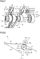
- the paddle members 15, as shown in FIG. 7 each include a paddle main body portion 51 and a shaft portion 52.
- the shaft portion 52 is fixed to a side of the paddle main body portion 51 in the sheet width direction.
- the paddle main body portion 51 and the shaft portion 52 are configured in cylindrical shapes of which central axes extend in the sheet width direction and arranged coaxially with an axis of the rotation shaft 731a.
- the paddle main body portion 51 has a smaller diameter than the second drive roller 731.
- the shaft portion 52 has a smaller diameter than the paddle main body portion 51.
- the rotation shaft 731a penetrates, in the sheet width direction, center parts of the paddle main body portion 51 and the shaft portion 52 in a diameter direction.
- the paddle main body portion 51 and the shaft portion 52 are rotatable independently of the rotation shaft 731a.
- the first drive transmission shaft 501 is arranged below the rotation shaft 731a of the second drive roller 731.
- the first drive transmission shaft 501 extends along the sheet width direction.
- the first drive transmission belt 502 is wound around the shaft portion 52 of the paddle member 15 and the first drive transmission shaft 501 via pulleys.
- the two first drive transmission belts 502 are wound around the one first drive transmission shaft 501, and are respectively wound around the shaft portions 52 of the separate paddle members 15.
- the first drive transmission belts 502 transmit a rotational force of the first drive transmission shaft 501 to the shaft portions 52 of the paddle members 15.
- the second drive transmission shaft 503 is arranged below the first drive transmission shaft 501.
- the second drive transmission shaft 503 extends along the sheet width direction.
- the second drive transmission belt 504 is wound around the first drive transmission shaft 501 and the second drive transmission shaft 503 via pulleys.
- the second drive transmission belt 504 transmits a rotational force of the second drive transmission shaft 503 to the first drive transmission shaft 501.
- the drive shaft 505 is arranged below the second drive transmission shaft 503.
- the drive shaft 505 extends along the sheet width direction.
- the third drive transmission belt 506 is wound around the second drive transmission shaft 503 and the drive shaft 505 via pulleys.
- the two third drive transmission belts 506 are wound around the one drive shaft 505, and are respectively wound around the separate second drive transmission shafts 503.
- the third drive transmission belts 506 transmit a rotational force of the drive shaft 505 to the second drive transmission shafts 503.
- the drive transmission gear 507 is provided on the drive shaft 505.
- the drive transmission gear 507 is arranged coaxially with the drive shaft 505, and rotates together with the drive shaft 505.
- the drive gear 508 is provided on a rotation shaft of the drive motor 509.
- the drive gear 508 is rotated by the drive motor 509.
- the drive gear 508 meshes with the drive transmission gear 507.
- the four paddle members 15 are driven to rotate simultaneously and are rotatable about the rotation shaft 731a of the second drive roller 731 independently of the second drive roller 731.
- the rotation of the paddle members 15, in other words, the operation of the paddle drive portion 161, is controlled by the post-processing control portion 100.
- the paddle member 15 includes the paddle main body portion 51 and a paddle elastic portion 53.
- the paddle main body portion 51 includes a base portion 511 which has formed therein a shaft hole and through which the rotation shaft 731a is inserted, and an arm portion 512 which is provided on an outer peripheral surface of the base portion 511.
- the arm portion 512 projects in a direction that crosses the axis of the rotation shaft 731a of the base portion 511 and that is away from an axial center.
- the arm portion 512 projects from the outer peripheral surface of the base portion 511 outward substantially in a tangent direction of the outer peripheral surface.
- the arm portion 512 is integrally formed with the base portion 511.
- the arm portion 512 is made of a material that has a higher modulus of rigidity than a material of the paddle elastic portion 53.
- the paddle elastic portion 53 projects longer than the arm portion 512 in a direction that crosses the axis of the rotation shaft 731a of the paddle main body portion 51 and that is away from the axial center.
- the paddle elastic portion 53 is attached to the arm portion 512, and projects longer than the arm portion 512 in the same direction as the arm portion 512.
- the paddle elastic portion 53 is configured of a material having a higher elasticity modulus than the arm portion 512 (the paddle main body portion 51), such as a rubber.
- FIGS. 8 to 11 are diagrams for illustrating a sheet loading operation performed by the sheet loading device 10. A description will be given of an operation of the paddle member 15 in the sheet loading device 10, with reference to FIGS. 8 to 11 .
- the paddle member 15 before a start of its operation, is made to stop its rotation in a state of being arranged at a retraction position where the arm portion 512 and the paddle elastic portion 53 project neither toward the processing tray 8 nor toward the loading tray 11. That is, the paddle member 15 stands by at a predetermined position.
- the paddle member 15 when out of use, the paddle member 15 does not interfere with discharging of a sheet P.
- a rotation speed of the discharge roller pair 73 is reduced by the time when the upstream end of the sheet P in the sheet discharge direction passes through the second nip portion 73N of the discharge roller pair 73.
- a discharge speed of the sheet P to be discharged by the discharge roller pair 73 is reduced to a predetermined discharge speed by the time the upstream end of the sheet P in the sheet discharge direction passes through the second nip portion 73N of the discharge roller pair 73.
- the paddle drive portion 161 makes the paddle member 15 start rotating.
- a rotation speed of the paddle member 15 is equal to the rotation speed of the discharge roller pair 73 at which the discharge roller pair 73 rotates when the upstream end of the sheet P in the sheet discharge direction passes through its second nip portion 73N.
- the paddle member 15 comes into contact with the upstream part (the rear end) of the sheet P in the discharge direction in which the sheet P is discharged by the discharge roller pair 73. Thereby, the paddle member 15 pushes down, toward the sheet loading surface 11a, the upstream part of the sheet P in the discharge direction, in which the sheet P has been discharged from the discharge roller pair 73, as if by slapping the upstream part from above.
- the paddle elastic portion 53 comes into contact with the upstream part of the discharged sheet P in the sheet discharge direction. Thereby, the paddle member 15 pulls the sheet P along the loading tray 11 toward the upstream side of the sheet P in the sheet discharge direction. Further, the paddle member 15 holds down the upstream part of the sheet P in the sheet discharge direction toward the sheet receiving wall 11b of the loading tray 11.
- the upstream part of the sheet P in the sheet discharge direction comes in contact with the sheet receiving wall 11b provided on the upstream side of the loading tray 11 in the sheet discharge direction.
- the sheet P is aligned at a predetermined position on the loading tray 11.
- the sheet receiving wall 11b has, on a rotational orbit of the paddle member 15, an unillustrated slit portion through which the paddle member 15 can pass.
- the arm portion 512 and the paddle elastic portion 53 reach the retraction position at which they do no project toward the loading tray 11.
- FIG. 12 is a block diagram showing an example of a control path for the sheet post-processing device 5.
- the post-processing control portion 100 (hereinafter referred to simply as the control portion 100) is constituted by a CPU (Central Processing Unit) which controls operations of various portions of the sheet post-processing device 5 including the sheet loading device 10, a ROM (Read Only Memory) which stores a control program therein, a RAM (Random Access Memory) which is used as an operation area for the CPU, etc.
- the control portion 100 controls the operations of the various portions of the sheet post-processing device 5 including the sheet loading device 10 by the CPU executing the control program stored in the ROM.
- the control portion 100 controls a punching processing operation performed by the punching processing portion 61 of the post-processing mechanism 6 and a staple processing operation performed by the staple processing portion 62 of the post-processing mechanism 6.
- the control portion 100 controls driving of the transport drive portion 70, and thereby controls rotating and stopping of the transport roller pair 71 and the intermediate roller pair 72.
- the control portion 100 controls driving of the discharge drive portion 90, and thereby controls rotating and stopping of the discharge roller pair 73 or reciprocating movement of the bundle discharge member 81.
- the control portion 100 controls driving of a nip release drive portion 91, and thereby controls operations of releasing and recovering the second nip portion 73N of the discharge roller pair 73 performed by the nip release mechanism 74.
- the control portion 100 after a first sheet is pulled into the processing tray 8, makes the nip release drive portion 91 drive the nip release mechanism 74 to release the second nip portion 73N. Then, after a second and subsequent sheets are pulled into the processing tray 8 and the staple processing is performed, the second nip portion 73N is recovered to discharge the sheet bundle onto the loading tray 11.
- the bundle discharge member 81 is moved to the downstream side in the sheet discharge direction, and the sheet bundle is pushed out and discharged onto the loading tray 11.
- the control portion 100 controls driving of the tray lifting-lowering drive portion 113, and thereby controls the operation of lifting-lowering the loading tray 11.
- the control portion 100 controls driving of the projection drive portion 131, and thereby controls movement of the projection member 13 between a projection position and a retraction position along the guide rail 801.
- the control portion 100 controls driving of the sheet holding drive portion 142, and thereby controls a swinging operation which the sheet holding member 14 performs, by rotating about the swing shaft 14a, to swing between the sheet-holding position and the retraction position.
- the control portion 100 controls driving of the paddle drive portion 161, and thereby controls a slapping operation which the paddle member 15 performs, by rotating about the rotation shaft 731a, to slap, toward the loading tray 11, a rear end of a sheet having passed through the discharge roller pair 73, and a holding operation which the paddle member 15 performs subsequently to the slapping operation to come into contact, from above, with the rear end part of the sheet having fallen into the loading tray 11 to hold the sheet down while pulling the sheet toward the upstream side.
- the loading tray 11 in a case of performing the above-described operation of lifting-lowering (positioning) the loading tray 11 in a mode in which sheets are loaded continuously one by one on the loading tray 11, in order to prevent the top surface detection sensor S3 from erroneously detecting a falling sheet or a curled rear end part of a sheet, the loading tray 11 is lifted and lowered with the sheet holding member 14 holding the sheets. At this time, depending on whether the lifting-lowering operation is finished with the top surface detection sensor S3 in an on state or the lifting-lowering operation is finished with the top surface detection sensor S3 in an off state, the following inconvenience may occur.
- control may be performed in such a manner that the top surface detection sensor S3 is confirmed to be on and then a top surface of sheets is detected, the loading tray 11 is once lowered and then the top surface detection sensor S3 is confirmed to be off, and then the loading tray 11 is lifted again and the lifting-lowering operation is finished with the top surface detection sensor S3 in the on state.
- the top surface of the sheets is located nearest the rotational orbit of the paddle member 15.
- the paddle member 15 has a role of pushing down a sheet toward the sheet loading surface 11a of the loading tray 11 as if by slapping a rear end of the sheet from above, pulling the sheet along the loading tray 11 toward the upstream side in the sheet discharge direction, and holding down an upstream part of the sheet in the sheet discharge direction toward the sheet receiving wall 11b of the loading tray 11, and thus it is preferable for the paddle member 15 to have a possible maximum paddle length.
- the top surface of the sheets loaded by a next lifting-lowering operation may overlap with the orbit of the paddle member 15 and make the paddle member 15 unrotatable (locked).
- the loading tray 11 does not rise to a predetermined position in the next lifting-lowering operation.
- a height difference between the discharge roller pair 73 and the top surface of the sheets is increased, and this may invite an unstable sheet discharge state in which, for example, a leading end of a sheet discharged by the discharge roller pair 73 is curled or a sheet is reversed, and cause poor alignment of sheets loaded on the loading tray 11.
- the loading tray 11 is lowered and the top surface detection sensor S3 is confirmed to be off, then the loading tray 11 is once lifted and the top surface detection sensor S3 is confirmed to be on, and after the top surface of the sheets is detected, the loading tray 11 is lowered again and the lifting-lowering operation is finished with the top surface detection sensor S3 in the off state.
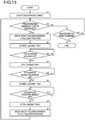
- FIG. 13 is a flowchart showing an example of control of the lifting-lowering operation of lifting and lowering the loading tray 11 performed in the sheet loading device 10 of the present embodiment.
- FIGS. 1 to 12 and later-described FIGS. 14 and 15 as necessary, along the steps shown in FIG. 13 , a description will be given of a method of positioning the loading tray 11 of the sheet loading device 10 at a reference position (home position).
- the sheet post-processing device 5 is in a mode (one-by-one mode) in which it processes sheets continuously one by one, and the loading tray 11 of the sheet loading device 10 is arranged at the reference position.
- step S1 When discharging of sheets onto the loading tray 11 is started from this state (step S1), the control portion 100 determines whether or not a predetermined number (here, ten) sheets have been discharged (step S2). If the predetermined number has not been reached (No in step S2), the control portion 100 determines whether or not the discharging of sheets has been finished (step S3). If the discharging of sheets has not been finished (No in step S3), the flow returns to step S2, and the discharging of sheets is continued. When the discharging of sheets has been finished (Yes in step S3), the processing is finished.
- a predetermined number here, ten
- step S2 In a case where the predetermined number of sheets have been discharged (Yes in step S2), the sheet holding member 14 is moved from the retraction position to the sheet-holding position (step S4). Then, the loading tray 11 is lowered (step S5).
- control portion 100 determines whether or not the top surface detection sensor S3 has been turned off (step S6). In a case where the top surface detection sensor S3 is on (No in step S6), the loading tray 11 continues to be lowered.
- FIG. 14 is a side sectional view of the sheet loading device 10, showing a state in which the top surface detection sensor S3 is off.
- the loading tray 11 has descended to a position at which a topmost sheet P1U of sheets P1 loaded on the sheet loading surface 11a does not overlap with a detection portion S3a of the top surface detection sensor S3.
- the loading tray 11 is lifted (step S7).
- control portion 100 determines whether or not the top surface detection sensor S3 has been turned on (step S8). In a case where the top surface detection sensor S3 is off (No in step S8), the loading tray 11 continues to be lifted.
- FIG. 15 is a side sectional view of the sheet loading device 10, showing a state in which the top surface detection sensor S3 is on.
- the loading tray 11 has ascended to a position at which the topmost sheet P1U of the sheets P1 loaded on the sheet loading surface 11a overlaps with the detection portion S3a of the top surface detection sensor S3.
- the loading tray 11 is lowered again (step S9).
- the control portion 100 determines whether or not the top surface detection sensor S3 has been turned off (step S10). In a case where the top surface detection sensor S3 is on (No in step S10), the loading tray 11 continues to be lowered. In a case where the top surface detection sensor S3 has been turned off as shown in FIG. 14 (Yes in step S10), the loading tray 11 is stopped (step S11). This position is the reference position of the loading tray 11. Thereafter, the sheet holding member 14 is moved to the retraction position (step S12) and the flow returns to step S2, and the similar processing is repeated.
- the operation of lifting-lowering the loading tray 11 is finished and the loading tray 11 is positioned at the reference position.
- the clearance between the rotational orbit of the paddle member 15 and the top surface of the sheets can constantly be widened by a certain distance. Accordingly, it is possible to achieve as long a paddle length of the paddle member 15 as possible while avoiding inconveniences such as the paddle member 15 becoming unable to rotate (locked state), unstable sheet discharge state occurring when loaded sheets are removed, etc.
- the topmost sheet surface is detected after the sheet holding member 14 is moved to the sheet-holding position, it is possible to prevent erroneous detection by the top surface detection sensor S3 due to a lifted or curled rear end of a sheet.
- the sheet holding member 14 can be detected by the top surface detection sensor S3 when detecting a position of the top surface of the sheets.
- the flag 11c (see FIG. 2 ) stops slightly before the lower limit detection sensor S4 is turned on when the operation of lifting-lowering the loading tray 11 is finished, in a next lifting-lowering operation, it is detected that the loading tray 11 has reached the lower limit position.
- the loading tray 11 can hardly descend in the next lifting-lowering operation, and thus, after the next lifting-lowering operation is finished, the position of the top surface of sheets loaded after the next lifting-lowering operation is finished comes above a detection position (upper limit position) of the top surface detection sensor S3, and thus it becomes impossible for the paddle member 15 to rotate (locked state).
- FIG. 18 is a side view of and around the discharge roller pair 73, showing a state in which the loading tray 11 has descended to the reference position in the sheet loading device 10 of the present embodiment.
- FIG. 18 when the lifting-lowering operation is finished and the loading tray 11 is positioned at the reference position after the state of the top surface detection sensor S3 changes from off to on to off, when a descending amount (descending distance) of a top surface of sheets from the detection position (indicated by a broken line L in FIG.
- d a thickness of a sheet bundle of a maximum number of sheets (for example, 100 sheets) dischargeable from the processing tray 8 onto the loading tray 11 at one time
- t a thickness of a sheet bundle of a maximum number of sheets (for example, 100 sheets) dischargeable from the processing tray 8 onto the loading tray 11 at one time
- a secured amount of sheets loadable on the sheet loading surface 11a in one event of the operation of lifting-lowering the loading tray 11 exceeds twice the maximum number of sheets in one sheet bundle.
- a sheet bundle of the maximum number of sheets can be loaded on the sheet loading surface 11a of the loading tray 11. Accordingly, even when the loading tray 11 reaches the lower limit position, the position of the top surface of the sheets does not exceed the detection position (upper limit position) of the top surface detection sensor S3, and thus it is possible to prevent the inconvenience of the paddle member 15 becoming unable to rotate (locked state).
- FIG. 19 is a flowchart showing an example of control in the discharging operation performed when the lower limit position of the loading tray 11 has been detected by the lower limit detection sensor S4.
- the sheet post-processing device 5 is set in a mode (bundle processing mode) in which the staple processing is performed with respect to a sheet bundle loaded on the processing tray 8, and the loading tray 11 of the sheet loading device 10 is arranged at the reference position.
- the control portion 100 detects a number A of sheets in the sheet bundle (step S2).
- the number of sheets in the sheet bundle can be detected by, for example, counting the number of sheets that pass the first sheet detection portion S1 (or the second sheet detection portion S2).
- the control portion 100 determines whether or not the lower limit detection sensor S4 is on (step S3).
- the lower limit detection sensor S4 is not in the on state (No in step S3), the loading tray 11 has not reached the lower limit position, and thus the flow proceeds to a loading-tray lifting-lowering routine shown in FIG. 13 (step S4).
- the loading tray 11 is lifted and lowered, and after the state of the top surface detection sensor S3 changes from off to on to off, the lifting-lowering operation is finished, and the loading tray 11 is positioned at the reference position.
- the reference position is below the detection position (upper limit position) of the top surface detection sensor S3 by a distance equal to twice the thickness of the maximum number of sheets (for example, 100 sheets) discharged onto the loading tray 11.
- step S5 it is determined whether or not the number A of sheets included in the discharged sheet bundle is equal to or larger than a predetermined number A1 (for example, 50) (step S5). In a case where A ⁇ A1 (Yes in step S5), the sheet bundle is discharged (step S6). Also, a cumulative number B of sheets having been discharged after the lower limit detection sensor S4 is turned into the on state is detected (step S7).
- a predetermined number A1 for example, 50
- the control portion 100 determines whether or not the cumulative number B of the discharged sheets is equal to or larger than a predetermined number B1 (step S8).
- step S8 In a case where B ⁇ B1 (No in step S8), there is a margin in the number of sheets loadable on the loading tray 11, the flow returns to step S2, where discharging of sheets onto the loading tray 11 is continued (steps S2 to S8). In a case where B ⁇ B1 (Yes in step S8), there is no margin left in the number of sheets loadable on the loading tray 11, and thus the discharging of sheets onto the loading tray 11 is stopped (step S9).
- step S5 it is determined that the discharging of a sheet bundle this time will leave no margin in the number of loadable sheets, and after the sheet bundle is discharged (step S10), the discharging operation is stopped (step S9).
- the threshold values A1 and B1 can be appropriately set in accordance with the maximum number of sheets in a sheet bundle dischargeable in one event of sheet discharge.
- the projection member 13 is displaced between the projection position at which a sheet discharged by the discharge roller pair 73 comes into contact with the top surface of the projection member 13 and the retraction position at which the projection member 13 is retracted to the upstream side in the sheet discharge direction, but a configuration is possible without the projection member 13.
- the image forming apparatus 200 in the image forming system S is a multifunction peripheral for monochrome printing, but this is not meant to limit the present disclosure.
- the image forming apparatus 200 may instead be, for example, a monochrome copier, a monochrome printer, or the like, or may instead be an image forming apparatus for color printing, such as a color copier, a color printer, or the like.
Landscapes
- Engineering & Computer Science (AREA)
- Mechanical Engineering (AREA)
- Physics & Mathematics (AREA)
- General Physics & Mathematics (AREA)
- Pile Receivers (AREA)
- Paper Feeding For Electrophotography (AREA)
Abstract
Description
- The present disclosure relates to a sheet loading device on which a sheet such as a paper sheet is loaded after an image is formed thereon by an image forming apparatus such as a copier, a facsimile machine, a printer, or the like, a sheet post-processing device provided therewith, and an image forming system provided therewith.
- Sheet post-processing devices have conventionally been used which are capable of stacking a plurality of sheets (paper sheets) on which images have been formed by an image forming apparatus such as a copier, a printer, or the like, and performing post-processing such as stapling processing of binding the stacked sheets as a sheet bundle with a staple, punching processing of forming a hole (punched hole) using a punching device, etc.
- Such conventional sheet post-processing devices each include a sheet loading device having a discharge roller pair which discharges a sheet having undergone post-processing and a loading tray on which the sheet discharged by the discharge roller pair is loaded. A known example of a sheet loading device includes a paddle member which slaps an upstream part (a rear end part) of a sheet in a discharge direction after the sheet passes through a nip portion of a discharge roller pair, and thereby makes the sheet fall onto the loading tray.
- For example, a sheet discharge device is known which is provided with a holding member rotatable about a rotation shaft arranged below a rotation shaft of a sheet discharge roller (a discharge roller pair). The holding member and the sheet discharge roller are respectively driven to rotate by a holding-member drive motor and a sheet-discharge drive motor, which are separate from each other. The holding member is caused to rotate by a driving force received from the holding-member drive motor, and thereby holds a rear end part of a sheet in a sheet discharge direction as if by slapping the rear end part from above.
- Another sheet discharge device is known which is provided with a scraping member; the scraping member is arranged coaxial with a driven discharge roller of a discharge rotary body pair (a discharge roller pair), and is driven to rotate by a sheet discharged by the discharge rotary body pair. The scraping member has a plurality of flexible blade members projecting from its outer peripheral surface. The blade members scrape a rear end part of a sheet having passed through the discharge rotary body pair, and further hold down the rear end part of the sheet loaded on a loading tray.
- An object of the present disclosure is to provide a sheet loading device capable of avoiding contact between a paddle member which slaps a rear end of a sheet down and a sheet on a loading tray, a post-processing device provided therewith, and an image forming system.
- According to an aspect of the present disclosure, a sheet loading device includes a discharge roller pair, a loading tray, a paddle member, a sheet holding member, a tray lifting-lowering drive portion, a top surface detection sensor, and a control portion. The discharge roller pair includes a drive roller and a driven roller which follows the drive roller to rotate, and discharges a sheet. The loading tray is arranged on a downstream side of the discharge roller pair with respect to a discharge direction of the sheet, and the sheet discharged by the discharge roller pair is loaded on the loading tray. The paddle member is arranged coaxial with the drive roller, and rotates in a same direction as the drive roller to thereby come into contact, from above, with an upstream part, in the discharge direction, of the sheet discharged by the discharge roller pair. The sheet holding member is arranged below the discharge roller pair, and is swingable between a holding position at which the sheet holding member holds the upstream part of the sheet in the discharge direction loaded on the loading tray and a retraction position at which the sheet holding member releases holding of the sheet. The tray lifting-lowering drive portion lifts and lowers the loading tray. The top surface detection sensor switches between an on state in which the top surface detection sensor performs detection of a sheet loading surface of the loading tray or of a top surface of the sheet loaded on the sheet loading surface and an off state in which the top surface detection sensor does not perform the detection. The control portion controls the tray lifting-lowering drive portion. The control portion is capable of performing a lifting-lowering operation to arrange the loading tray at a reference position by lowering the loading tray with the sheet holding member arranged at the holding position to turn the top surface detection sensor into the off state, then lifting the loading tray to turn the top surface detection sensor into the on state, and then lowering the loading tray again to turn the top surface detection sensor into the off state and stop the loading tray. With the loading tray at the reference position, a predetermined clearance is provided between the top surface of the sheet loaded on the loading tray and a rotational orbit of the paddle member.
- Still other objects of the present disclosure and specific advantages provided by the present disclosure will be made further apparent from the following description of an embodiment.
-
-
FIG.1 is a schematic diagram of an image forming system S including animage forming apparatus 200 and asheet post-processing device 5 according to an embodiment of the present disclosure. -
FIG. 2 is a side sectional view showing an internal structure of thesheet post-processing device 5 of the present embodiment. -
FIG. 3 is an enlarged sectional view of and around aprocessing tray 8 shown inFIG. 2 . -
FIG. 4 is a perspective view showing a structure of aprojection drive portion 131 in asheet loading device 10 of the present embodiment, showing a state in which aprojection member 13 is located at a retraction position. -
FIG. 5 is a perspective view showing the structure of theprojection drive portion 131 in thesheet loading device 10 of the present embodiment, showing a state in which theprojection member 13 is located at a projection position. -
FIG. 6 is a perspective view showing a structure of adischarge drive portion 90 and apaddle drive portion 161 in thesheet loading device 10 of the present embodiment. -
FIG. 7 is a partial perspective view of and around adischarge roller pair 73 in thesheet loading device 10 of the present embodiment. -
FIG. 8 is a diagram for illustrating a sheet loading operation performed by thesheet loading device 10 of the present embodiment, showing a state in which apaddle member 15 is located at a retraction position. -
FIG. 9 is a diagram for illustrating the sheet loading operation performed by thesheet loading device 10 of the present embodiment, showing a state in which thepaddle member 15 has started to rotate from the state inFIG. 8 . -
FIG. 10 is a diagram for illustrating the sheet loading operation performed by thesheet loading device 10 of the present embodiment, showing a state in which thepaddle member 15 has rotated from the state inFIG. 9 into contact with an upstream part of a sheet P in a discharge direction of the sheet. -
FIG. 11 is a diagram for illustrating the sheet loading operation performed by thesheet loading device 10 of the present embodiment, showing a state in which thepaddle member 15 rotates from the state inFIG. 10 toward the retraction position. -
FIG. 12 is a block diagram showing an example of control paths in thesheet post-processing device 5. -
FIG. 13 is a flowchart showing an example of control in a lifting-lowering operation of aloading tray 11 performed in thesheet loading device 10 of the present embodiment. -
FIG. 14 is a side sectional view of thesheet loading device 10, showing a state in which a top surface detection sensor S3 is off. -
FIG. 15 is a side sectional view of thesheet loading device 10, showing a state in which the top surface detection sensor S3 is on. -
FIG. 16 is a side sectional view of thesheet loading device 10 where the top surface detection sensor S3 is arranged at a position overlapping with a leading end of asheet holding member 14 arranged at a holding position, showing a state in which the upper surface detection sensor S3 is off. -
FIG. 17 is a side sectional view of thesheet loading device 10 where the top surface detection sensor S3 is arranged at the position overlapping with the leading end of thesheet holding member 14 arranged at the holding position, showing a state in which the upper surface sensor S3 is on. -
FIG. 18 is a side view of and around thedischarge roller pair 73, showing a state in which theloading tray 11 has descended to a reference position, theloading tray 11 having descended by a descent distance d twice as long as the thickness t of a sheet bundle of a maximum number of sheets. -
FIG. 19 is a flowchart showing an example of control in a discharging operation performed when a lower limit position of theloading tray 11 has been detected by a lower limit detection sensor S4. - Hereinafter, an embodiment of the present disclosure will be described with reference to the accompanying drawings.
FIG. 1 is a schematic diagram of an image forming system S which includes animage forming apparatus 200 and asheet post-processing device 5 according to an embodiment of the present disclosure. The image forming system S includes theimage forming apparatus 200 and thesheet post-processing device 5. - The
image forming apparatus 200 is what is called a monochrome multifunction peripheral having functions of, for example, printing (print), scanning (image reading), and facsimile transmission. In theimage forming apparatus 200, as shown inFIG. 1 , adocument transport portion 203 is placed on a top surface of amain body portion 201. At a position that is below thedocument transport portion 203 but is inside themain body portion 201, animage reading portion 204 is provided. Theimage reading portion 204 reads an image on a document loaded on thedocument transport portion 203 or an image on a document placed on an unillustrated contact glass provided on a top surface of theimage reading portion 204. - The
image forming apparatus 200 further includes asheet feeding portion 205, asheet transport portion 206, anexposure portion 207, animage forming portion 208, atransfer portion 209, afixing portion 210, asheet discharge portion 211, arelay portion 212, and a mainbody control portion 213. - The
sheet feeding portion 205 holds a plurality of sheets P, and feeds them out one by one, separately from each other, during printing. Thesheet transport portion 206 transports a sheet P fed out from thesheet feeding portion 205 to thetransfer portion 209 and thefixing portion 210, and further transports the sheet P having undergone fixing to thesheet discharge portion 211 or to therelay portion 212. Theexposure portion 207 emits laser light controlled based on image data toward theimage forming portion 208. - The
image forming portion 208 includes aphotosensitive drum 2081 as an image carrier and adevelopment device 2082. In theimage forming portion 208, the laser light emitted from theexposure portion 207 forms, on a surface of thephotosensitive drum 2081, an electrostatic latent image based on a document image. Thedevelopment device 2082 supplies toner to the electrostatic latent image to develop it into a toner image. Thetransfer portion 209 transfers, onto a sheet P, the toner image formed by theimage forming portion 208 on the surface of thephotosensitive drum 2081. Thefixing portion 210 applies heat and pressure to the sheet P having the toner image transferred thereon to fix the toner image on the sheet P. - After the fixing, the sheet P is transported to the
sheet discharge portion 211 or to therelay portion 212. Thesheet discharge portion 211 is arranged below theimage reading portion 204. Thesheet discharge portion 211 has an opening in its front face, and the sheet P after the printing (a printed sheet) is taken out from the front-face side. Therelay portion 212 is arranged below thesheet discharge portion 211. Therelay portion 212 has its downstream end in a sheet transport direction connected to thesheet post-processing device 5. The sheet P (printed matter) after the printing having been sent to therelay portion 212 passes through therelay portion 212 to be transported into thesheet post-processing device 5. - The main
body control portion 213 includes a CPU, an image processing portion, and a storage portion, of which none is illustrated, and other unillustrated electronic circuits and components. The CPU, based on a control program and control data stored in the storage portion, controls operations of various constituent elements provided in theimage forming apparatus 200 to perform processing related to functions of theimage forming apparatus 200. Thesheet feeding portion 205, thesheet transport portion 206, theexposure portion 207, theimage forming portion 208, thetransfer portion 209, and the fixingportion 210 each individually receive an instruction from the mainbody control portion 213, and coordinate with each other to perform printing with respect to the sheet P. The storage portion is configured as a combination of non-volatile storage devices such as a program ROM (Read Only Memory) and a data ROM and a volatile storage device such as a RAM (Random Access Memory). - The
sheet post-processing device 5 is attachably and detachably connected to a side face of theimage forming apparatus 200. Thesheet post-processing device 5 includes apost-processing housing 50, and apost-processing mechanism 6, asheet transport mechanism 7, aprocessing tray 8, asheet loading device 10, and apost-processing control portion 100, which are arranged inside thepost-processing housing 50. - In such a side face of the
post-processing housing 50 as faces theimage forming apparatus 200, asheet receiving port 41 is provided. After passing through therelay portion 212, the sheet P passes through thesheet receiving port 41 to be transported into thesheet post-processing device 5. - A
sheet transport path 42 extends from thesheet receiving port 41, in a direction away from the image forming apparatus 200 (leftward inFIG. 1 ), to a position above theprocessing tray 8. - The
post-processing mechanism 6 performs predetermined post-processing with respect to the sheet P transported along thesheet transport path 42. Thepost-processing mechanism 6 includes apunching processing portion 61 and astaple processing portion 62. - The punching
processing portion 61 is arranged at an intermediate position between thesheet receiving port 41, which is an upstream end of thesheet transport path 42 in the sheet transport direction (an arrow-Hl 1 direction inFIG. 2 ), and a downstream end of thesheet transport path 42. The punchingprocessing portion 61 performs punching processing with respect to the sheet P transported along thesheet transport path 42 to form a punched hole (a binding hole) in the sheet P. Here, the punched hole is formed along one of opposite edges of the sheet P in its width direction which is perpendicular to the sheet transport direction. - The
staple processing portion 62 is arranged at a position that is below thesheet transport path 42 but is on an upstream side of theprocessing tray 8 in the sheet transport direction. Thesheet post-processing device 5, by using thestaple processing portion 62, can perform staple processing (binding processing) of binding a bundle of sheets P (hereinafter referred to simply as "sheet bundle") placed on theprocessing tray 8 with a staple needle to bind the sheet bundle. Here, what is called edge binding processing is performed, in which a sheet bundle is bound with a staple needle at a corner or at an edge. - The
sheet transport mechanism 7 transports the sheet P in the sheet transport direction which is along thesheet transport path 42. Thesheet transport mechanism 7 has a transport roller pair 71 (seeFIG. 2 ), anintermediate roller pair 72, and adischarge roller pair 73, which are arranged in this order from an upstream side in the sheet transport direction. - The
processing tray 8 is arranged below a downstream part of thesheet transport path 42 in a sheet discharge direction. In other words, theprocessing tray 8 is located at a position that is on a downstream side of theintermediate roller pair 72 in the sheet discharge direction but is below theintermediate roller pair 72. A plurality of sheets P having passed through thesheet transport path 42 to reach theprocessing tray 8 are placed on theprocessing tray 8, where the staple processing is performed on them by thestaple processing portion 62. - The
sheet loading device 10 has aloading tray 11 arranged on a downstream side of theprocessing tray 8 in the sheet discharge direction to be adjacent to theprocessing tray 8. The sheet bundle, with respect to which the staple processing has been completed on theprocessing tray 8, is discharged by thedischarge roller pair 73 to be loaded on theloading tray 11. Here, in a case where thestaple processing portion 62 does not perform the staple processing, the sheets P are transported to theloading tray 11 without being loaded on theprocessing tray 8. A detailed configuration of thesheet loading device 10 will be described later. - The
post-processing control portion 100 includes a CPU and a storage portion, of which neither is illustrated, and other unillustrated electronic circuits and components. Thepost-processing control portion 100 is communicably connected to the mainbody control portion 213. Thepost-processing control portion 100 receives an instruction from the mainbody control portion 213, and, by using the CPU, based on a control program and control data stored in the storage portion, controls operations of various constituent elements provided in thesheet post-processing device 5 to perform processing related to functions of thesheet post-processing device 5. Thepost-processing mechanism 6, thesheet transport mechanism 7, theprocessing tray 8, and thesheet loading device 10 each individually receive an instruction from thepost-processing control portion 100, and coordinate with each other to perform the post-processing with respect to the sheet P. The storage portion is configured as a combination of storage devices such as a program ROM, a data ROM, a RAM, etc., of which none is illustrated. A detailed control path in thepost-processing control portion 100 will be described later. -
FIG. 2 is a side sectional view showing an internal structure of thesheet post-processing device 5.FIG. 3 is a side sectional view showing a structure of and around theprocessing tray 8 shown inFIG. 2 . Thetransport roller pair 71 is arranged on a downstream side of the punchingprocessing portion 61 in the sheet transport direction (the arrow-Hll direction) to be adjacent to thepunching processing portion 61. Thetransport roller pair 71 transports a sheet that has undergone the punching processing or a sheet that has not undergone the punching processing to a downstream side in the sheettransport direction HI 1. - The
intermediate roller pair 72 is arranged, on thesheet transport path 42, at a position between an upstream-side end part and a downstream-side end part of thesheet transport path 42 in the sheet transport direction. Theintermediate roller pair 72 includes afirst drive roller 721 which rotates on receiving a driving force from a transport drive portion 70 (seeFIG. 12 ), and a first drivenroller 722 which follows thefirst drive roller 721 to rotate. Thefirst drive roller 721 and the first drivenroller 722 are in contact with each other under a predetermined nip pressure therebetween to form afirst nip portion 72N which nips and transports a sheet. - Immediately near the
intermediate roller pair 72 on its downstream side, a first sheet detection portion S1 is arranged. The first sheet detection portion S1 is a sensor which optically detects a sheet, and detects that a leading end of a sheet transported by thetransport roller pair 71 has entered into theintermediate roller pair 72. The first sheet detection portion S1 also detects that the sheet transported by theintermediate roller pair 72 has passed through theintermediate roller pair 72. - The
discharge roller pair 73 is arranged on a downstream side of thesheet transport path 42 in the sheet transport direction. Thedischarge roller pair 73 includes asecond drive roller 731 which rotates on receiving a driving force from a discharge drive portion 90 (seeFIG. 12 ), and a second drivenroller 732 which follows thesecond drive roller 731 to rotate. Thesecond drive roller 731 and the second drivenroller 732 are in contact with each other under a predetermined nip pressure therebetween to form asecond nip portion 73N which nips and transports a sheet. Thesecond nip portion 73N is released by a nip release mechanism 74 (seeFIG. 12 ) when thestaple processing portion 62 performs the staple processing. - Immediately near the
discharge roller pair 73 on its downstream side, a second sheet detection portion S2 is arranged. The second sheet detection portion S2 includes an actuator and a photosensor; the actuator has a contact piece, which a sheet discharged by thedischarge roller pair 73 comes into contact with, and a detection piece, and the photosensor has a light emitter and a light receiver which are arranged facing each other with the detection piece located therebetween. When the leading end of a sheet transported by theintermediate roller pair 72 comes into contact with the contact piece, the actuator rotationally moves in a clockwise direction, so that the detection piece moves out of an optical path extending from the light emitter to the light receiver. Thereby, it is detected that a leading end of the sheet has entered thedischarge roller pair 73 and that the sheet is being discharged by thedischarge roller pair 73. On the other hand, when a rear end of the sheet passes by the contact piece, the actuator rotationally moves in a counterclockwise direction, so that the detection piece moves into the optical path extending from the light emitter to the light receiver. Thereby, it is detected that the rear end of the sheet has passed through thedischarge roller pair 73. - Below the
sheet transport path 42, theprocessing tray 8 is arranged. Theprocessing tray 8, with the second nipportion 73N of thedischarge roller pair 73 released, receives the sheet transported by theintermediate roller pair 72 to have the sheet loaded thereon. A sheet bundle loaded on theprocessing tray 8 is subjected to the staple processing performed by thestaple processing portion 62. Theprocessing tray 8, having its downstream-side end part (left end part inFIG. 2 ) in the sheet transport direction located near thedischarge roller pair 73 and its upstream-side end part (right end part inFIG. 2 ) located below theintermediate roller pair 72, is inclined downward from its downstream-side end part toward its upstream-side end part in the sheet transport direction. - The
processing tray 8 is provided with abundle discharge member 81 which supports an upstream-side end part (a rear end) of a sheet bundle. Thebundle discharge member 81 is fixed to a drive belt (not shown) arranged on a rear-surface side of theprocessing tray 8, and part of thebundle discharge member 81 projects from a placing surface of theprocessing tray 8 in an L-shape in side view. Along with the drive belt being rotationally moved by the discharge drive portion 90 (seeFIG. 12 ), thebundle discharge member 81 reciprocates along the placing surface of theprocessing tray 8 in the sheet transport direction. - A sheet bundle loaded on the
processing tray 8 and having been subjected to the staple processing by thestaple processing portion 62 is discharged to thesheet loading device 10 by thedischarge roller pair 73 with the second nipportion 73N recovered or by thebundle discharge member 81. - The
sheet loading device 10 has loaded thereon sheets having been subjected to the post-processing by thepost-processing mechanism 6. Thesheet loading device 10 includes theloading tray 11, a pair ofcursor members 12, aprojection member 13, asheet holding member 14, and apaddle member 15. - The
loading tray 11 is arranged on a downstream side of thedischarge roller pair 73 with respect to the sheet transport direction (hereinafter may also be referred to as the sheet discharge direction), and is a final destination to which a sheet is discharged in thesheet post-processing device 5. Theloading tray 11 has asheet loading surface 11a on which are loaded sheets discharged by thedischarge roller pair 73 or by thebundle discharge member 81, such as sheets having been subjected to the punching processing by the punchingprocessing portion 61, a sheet bundle having been subjected to the staple processing by thestaple processing portion 62, etc. Thesheet loading surface 11a is highest at its downstream-end part in the sheet discharge direction, and is inclined downward toward its upstream-side end part. - The upstream-side end part of the
sheet loading surface 11a is located below thedischarge roller pair 73. Immediately near thesheet loading surface 11a on its upstream side, asheet receiving wall 11b is provided upright. Thesheet receiving wall 11b receives the upstream-side end part (the rear end) of a sheet that comes sliding down thesheet loading surface 11a. - The
loading tray 11 is configured to be able to be lifted and lowered by a tray lifting-lowering drive portion 113 (seeFIG. 12 ) in accordance with an amount of sheets loaded on thesheet loading surface 11a. At a position that is slightly downstream of the upstream-side end part of theloading tray 11, a top surface detection sensor S3 is arranged. The top surface detection sensor S3 is a photosensor that detects thesheet loading surface 11a or a top surface of a sheet loaded on thesheet loading surface 11a. In accordance with a detection signal of the top surface detection sensor S3, an operation of lifting-lowering (positioning) theloading tray 11 performed by the tray lifting-loweringdrive portion 113 is controlled. The operation of lifting-lowering theloading tray 11 is performed once for every predetermined number of sheets (for example, every 10 sheets) or at predetermined time intervals (for example, every several seconds). Thereby, a position of a topmost surface of sheets on thesheet loading surface 11a is maintained at a constant height. - In a lower part of the
post-processing housing 50, a lower limit detection sensor S4 is provided which detects a lower limit position of theloading tray 11. The lower limit detection sensor S4 is a photosensor similar to the top surface detection sensor S3, and can detect, when an optical path of a detection portion is blocked by aflag 11c provided on and projecting from theloading tray 11, that theloading tray 11 has descended to the lower limit position. Here, as the top surface detection sensor S3 and the lower limit detection sensor S4, other sensors may be used instead of photosensors. Details of the operation of lifting-lowering theloading tray 11 will be described later. - The pair of
cursor members 12 are supported by aholder 121 through which ashaft 122 is inserted. Theshaft 122 is supported by thepost-processing housing 50 so as to extend along a sheet width direction above thedischarge roller pair 73. Theholder 121 is supported by theshaft 122 so as to be movable along the sheet width direction. Theholder 121 supports the pair ofcursor members 12 such that leading end parts of the pair ofcursor members 12 are swingable in an up-down direction. - The
projection member 13 is a rod-shaped member having a predetermined width in the sheet width direction and extending in the sheet discharge direction in an arc shape, and is arranged below asheet discharge port 2. In detail, theprojection member 13 is arranged below theprocessing tray 8 so as to be below a discharge path via which a sheet is discharged from thedischarge roller pair 73 along theprocessing tray 8. In the present embodiment, theprojection member 13 is arranged, for example, at each of two positions in the sheet width direction, the two positions each being at a predetermined distance from a center part of theloading tray 11 in the sheet width direction. Here, theprojection members 13 are arranged at positions different from the position of thepaddle member 15 with respect to the sheet width direction. - The
projection member 13 is supported by aprojection drive portion 131 shown inFIGS. 4 and5 , and displaced by theprojection drive portion 131 along the sheet discharge direction. Theprojection drive portion 131 includes aguide rail 801, a drivetransmission gear group 802, adrive transmission shaft 803, adrive shaft 804, adrive transmission belt 805, adrive belt 806, and adrive motor 807. - Two
guide rails 801, two drivetransmission gear groups 802, twodrive transmission shafts 803, and twodrive transmission belts 805 are provided corresponding to the twoprojection members 13. Onedrive shaft 804, onedrive belt 806, and onedrive motor 807 are provided. - The
guide rail 801 is arranged on an upstream side of thedischarge roller pair 73 in the sheet discharge direction. Theguide rail 801 is an open-topped gutter-shaped member, extending in an arc shape in the sheet discharge direction like theprojection member 13. Theguide rail 801 accommodates and supports theprojection member 13 inside thereof. - The drive
transmission gear group 802 is arranged below theguide rail 801. The drivetransmission gear group 802 is composed of a plurality of gears in mesh with each other, and includes apinion gear 8021 at an end on a side of theguide rail 801, and adrive transmission gear 8022 at an end on a side of thedrive transmission shaft 803. - The
pinion gear 8021 is arranged directly under theguide rail 801. On a lower-face side of theprojection member 13, there is formed a rack (not shown) of a rack-and-pinion gear mechanism. The rack has a plurality of teeth aligned along the sheet discharge direction. Thepinion gear 8021 meshes with the rack of theprojection member 13. Here, in theguide rail 801, at a position adjacent to thepinion gear 8021, there is provided an unillustrated window portion via which thepinion gear 8021 and theprojection member 13 mesh with each other. - The
drive transmission shaft 803 is arranged in a lower part of the drivetransmission gear group 802. Thedrive transmission shaft 803 extends along the sheet width direction. Thedrive transmission gear 8022 of the drivetransmission gear group 802 is arranged coaxially with thedrive transmission shaft 803, and rotates together with thedrive transmission shaft 803. - The
drive shaft 804 is arranged below thedrive transmission shaft 803. Thedrive shaft 804 extends along the sheet width direction. - The
drive transmission belt 805 is wound around thedrive transmission shaft 803 and thedrive shaft 804 via pulleys. In detail, the twodrive transmission belts 805 are wound around theone drive shaft 804, and are respectively wound around the separatedrive transmission shafts 803. Thedrive transmission belts 805 transmits a rotational force of thedrive shaft 804 to thedrive transmission shafts 803. - The
drive belt 806 is wound around thedrive shaft 804 and a rotation shaft of thedrive motor 807 via pulleys. Thedrive belt 806 is rotated by thedrive motor 807. - In the
projection drive portion 131, when thedrive motor 807 rotates, a rotational force of thedrive motor 807 is transmitted via thedrive belt 806 to thedrive shaft 804, so that thedrive shaft 804 rotates. When thedrive shaft 804 rotates, the rotational force is transmitted via thedrive transmission belt 805 to thedrive transmission shaft 803. When thedrive transmission shaft 803 rotates, the rotational force is transmitted via the drivetransmission gear group 802 to thepinion gear 8021. Thereby, the twoprojection members 13 are simultaneously displaced along the sheet discharge direction. The displacement of theprojection members 13, in other words, the operation of theprojection drive portion 131, is controlled by thepost-processing control portion 100. - Referring back to
FIG. 3 , thesheet holding member 14 is arranged on an upstream side of theloading tray 11 in the sheet discharge direction. Thesheet holding member 14 is arranged below arotation shaft 731a of thesecond drive roller 731 of thedischarge roller pair 73. In the present embodiment, as thesheet holding member 14, for example, twosheet holding members 14 are arranged to be spaced from each other by a predetermined distance on theloading tray 11 in the sheet width direction. Here, thesheet holding members 14 are arranged at positions different from the position of thepaddle member 15 with respect to the sheet width direction. - The
sheet holding member 14 is a rod-shaped member having a predetermined width in the sheet width direction and extending substantially in the up-down direction. Thesheet holding member 14 is, at its lower end part, swingably supported about aswing shaft 14a which extends along the sheet width direction as a swing fulcrum. Thesheet holding member 14 is caused by a sheet holding drive portion 142 (seeFIG. 12 ) to swing about theswing shaft 14a in the sheet discharge direction, with its upper end part as a free end. Thesheet holding member 14 is displaced between a holding position (seeFIG. 14 ) for holding the upstream part of a sheet loaded on theloading tray 11 in the sheet discharge direction and a retraction position (seeFIG. 3 ) for releasing the holding of the sheet. - The
sheet holding member 14 is, as shown inFIG. 3 , before a sheet discharging operation is started, stationary at the retraction position where it does not project toward theloading tray 11. In this manner, thesheet holding member 14, when out of use, does not interfere with discharging of a sheet. - Subsequently, the
paddle member 15 is rotated, and, before thepaddle member 15 passes an upstream end of theloading tray 11 in the sheet discharge direction, swinging of thesheet holding member 14 is started. Then, thesheet holding member 14 is, as shown inFIG. 14 , displaced to the sheet-holding position where it holds the upstream part of a sheet loaded on theloading tray 11 in the sheet discharge direction. - According to this configuration, it is possible to hold a rear end of a curled sheet from above by means of the
sheet holding member 14. Thereby, even a case where the discharging and the loading of sheets with respect to theloading tray 11 are performed at high speed can be handled, so that the upstream part of a sheet loaded on theloading tray 11 in the sheet discharge direction can be held from above, and sheets on theloading tray 11 can be aligned preferably. - The
paddle member 15 is arranged coaxially with thedischarge roller pair 73. In detail, thepaddle member 15 is arranged coaxially with therotation shaft 731a of thesecond drive roller 731 extending along the sheet width direction. More in detail, in the present embodiment, twopaddle members 15 are provided coaxially with therotation shaft 731a of each of the twosecond drive rollers 731, such that a total of fourpaddle members 15 are provided. -
FIG. 6 is a perspective view showing a configuration of thedischarge drive portion 90 and apaddle drive portion 161 in thesheet loading device 10. The twosecond drive rollers 731 are simultaneously driven to rotate by thedischarge drive portion 90. Thedischarge drive portion 90, as shown inFIG. 6 , includes adrive transmission shaft 301, a firstdrive transmission belt 302, adrive shaft 303, a seconddrive transmission belt 304, adrive transmission gear 305, adrive gear 306, and adrive motor 307. - Two
drive transmission shafts 301, two firstdrive transmission belts 302, and two seconddrive transmission belts 304 are provided corresponding to the tworotation shafts 731a of the twosecond drive rollers 731. Onedrive shaft 303, onedrive transmission gear 305, onedrive gear 306, and onedrive motor 307 are provided. - The
drive transmission shaft 301 is arranged below therotation shaft 731a of thesecond drive roller 731. Thedrive transmission shaft 301 extends along the sheet width direction. - The first
drive transmission belt 302 is wound around therotation shaft 731a of thesecond drive roller 731 and thedrive transmission shaft 301 via pulleys. The firstdrive transmission belt 302 transmits a rotational force of thedrive transmission shaft 301 to therotation shaft 731a. - The
drive shaft 303 is arranged below thedrive transmission shaft 301. Thedrive shaft 303 extends along the sheet width direction. - The second
drive transmission belt 304 is wound around thedrive transmission shaft 301 and thedrive shaft 303 via pulleys. In detail, the two seconddrive transmission belts 304 are wound around theone drive shaft 303, and are respectively wound around the separatedrive transmission shafts 301. The seconddrive transmission belts 304 transmit a rotational force of thedrive shaft 303 to thedrive transmission shafts 301. - The
drive transmission gear 305 is provided on thedrive shaft 303. Thedrive transmission gear 305 is arranged coaxially with thedrive shaft 303, and rotates together with thedrive shaft 303. - The
drive gear 306 is provided on a rotation shaft of thedrive motor 307. Thedrive gear 306 is rotated by thedrive motor 307. Thedrive gear 306 meshes with thedrive transmission gear 305. - In the
discharge drive portion 90, when thedrive motor 307 rotates, a rotational force of thedrive motor 307 is transmitted via thedrive gear 306 and thedrive transmission gear 305 to thedrive shaft 303, so that thedrive shaft 303 rotates. When thedrive shaft 303 rotates, the rotational force is transmitted via the seconddrive transmission belt 304 to thedrive transmission shaft 301. When thedrive transmission shaft 301 rotates, the rotational force is transmitted via the firstdrive transmission belt 302 to therotation shaft 731a of thesecond drive roller 731. Thereby, the twosecond drive rollers 731 are simultaneously driven to rotate. The rotation of thesecond drive rollers 731, in other words, the operation of thedischarge drive portion 90, is controlled by thepost-processing control portion 100. - The four
paddle members 15 are simultaneously driven to rotate by thepaddle drive portion 161. Thepaddle drive portion 161, as shown inFIG. 6 , includes a firstdrive transmission shaft 501, a firstdrive transmission belt 502, a seconddrive transmission shaft 503, a seconddrive transmission belt 504, adrive shaft 505, a thirddrive transmission belt 506, adrive transmission gear 507, adrive gear 508, and adrive motor 509. - Four first
drive transmission belts 502 are provided corresponding to the fourpaddle members 15. Two firstdrive transmission shafts 501, two seconddrive transmission shafts 503, two seconddrive transmission belts 504, and two thirddrive transmission belts 506 are provided corresponding to the tworotation shafts 731a of the twosecond drive rollers 731. Onedrive shaft 505, onedrive transmission gear 507, onedrive gear 508, and onedrive motor 509 are provided. - The
paddle members 15, as shown inFIG. 7 , each include a paddlemain body portion 51 and ashaft portion 52. Theshaft portion 52 is fixed to a side of the paddlemain body portion 51 in the sheet width direction. The paddlemain body portion 51 and theshaft portion 52 are configured in cylindrical shapes of which central axes extend in the sheet width direction and arranged coaxially with an axis of therotation shaft 731a. The paddlemain body portion 51 has a smaller diameter than thesecond drive roller 731. Theshaft portion 52 has a smaller diameter than the paddlemain body portion 51. Therotation shaft 731a penetrates, in the sheet width direction, center parts of the paddlemain body portion 51 and theshaft portion 52 in a diameter direction. The paddlemain body portion 51 and theshaft portion 52 are rotatable independently of therotation shaft 731a. - The first
drive transmission shaft 501 is arranged below therotation shaft 731a of thesecond drive roller 731. The firstdrive transmission shaft 501 extends along the sheet width direction. - The first
drive transmission belt 502 is wound around theshaft portion 52 of thepaddle member 15 and the firstdrive transmission shaft 501 via pulleys. In detail, the two firstdrive transmission belts 502 are wound around the one firstdrive transmission shaft 501, and are respectively wound around theshaft portions 52 of theseparate paddle members 15. The firstdrive transmission belts 502 transmit a rotational force of the firstdrive transmission shaft 501 to theshaft portions 52 of thepaddle members 15. - The second
drive transmission shaft 503 is arranged below the firstdrive transmission shaft 501. The seconddrive transmission shaft 503 extends along the sheet width direction. - The second
drive transmission belt 504 is wound around the firstdrive transmission shaft 501 and the seconddrive transmission shaft 503 via pulleys. The seconddrive transmission belt 504 transmits a rotational force of the seconddrive transmission shaft 503 to the firstdrive transmission shaft 501. - The
drive shaft 505 is arranged below the seconddrive transmission shaft 503. Thedrive shaft 505 extends along the sheet width direction. - The third
drive transmission belt 506 is wound around the seconddrive transmission shaft 503 and thedrive shaft 505 via pulleys. In detail, the two thirddrive transmission belts 506 are wound around theone drive shaft 505, and are respectively wound around the separate seconddrive transmission shafts 503. The thirddrive transmission belts 506 transmit a rotational force of thedrive shaft 505 to the seconddrive transmission shafts 503. - The
drive transmission gear 507 is provided on thedrive shaft 505. Thedrive transmission gear 507 is arranged coaxially with thedrive shaft 505, and rotates together with thedrive shaft 505. - The
drive gear 508 is provided on a rotation shaft of thedrive motor 509. Thedrive gear 508 is rotated by thedrive motor 509. Thedrive gear 508 meshes with thedrive transmission gear 507. - In the
paddle drive portion 161, when thedrive motor 509 rotates, a rotational force of thedrive motor 509 is transmitted via thedrive gear 508 and thedrive transmission gear 507 to thedrive shaft 505, so that thedrive shaft 505 rotates. When thedrive shaft 505 rotates, the rotational force is transmitted via the thirddrive transmission belt 506 to the seconddrive transmission shaft 503. When the seconddrive transmission shaft 503 rotates, the rotational force is transmitted via the seconddrive transmission belt 504 to the firstdrive transmission shaft 501. When the firstdrive transmission shaft 501 rotates, the rotational force is transmitted via the firstdrive transmission belt 502 to theshaft portion 52 of thepaddle member 15. With this arrangement, the fourpaddle members 15 are driven to rotate simultaneously and are rotatable about therotation shaft 731a of thesecond drive roller 731 independently of thesecond drive roller 731. The rotation of thepaddle members 15, in other words, the operation of thepaddle drive portion 161, is controlled by thepost-processing control portion 100. - The
paddle member 15, as shown inFIG. 7 , includes the paddlemain body portion 51 and a paddleelastic portion 53. The paddlemain body portion 51 includes abase portion 511 which has formed therein a shaft hole and through which therotation shaft 731a is inserted, and anarm portion 512 which is provided on an outer peripheral surface of thebase portion 511. - The
arm portion 512 projects in a direction that crosses the axis of therotation shaft 731a of thebase portion 511 and that is away from an axial center. In detail, thearm portion 512 projects from the outer peripheral surface of thebase portion 511 outward substantially in a tangent direction of the outer peripheral surface. Thearm portion 512 is integrally formed with thebase portion 511. Thearm portion 512 is made of a material that has a higher modulus of rigidity than a material of the paddleelastic portion 53. - The paddle
elastic portion 53 projects longer than thearm portion 512 in a direction that crosses the axis of therotation shaft 731a of the paddlemain body portion 51 and that is away from the axial center. In detail, the paddleelastic portion 53 is attached to thearm portion 512, and projects longer than thearm portion 512 in the same direction as thearm portion 512. The paddleelastic portion 53 is configured of a material having a higher elasticity modulus than the arm portion 512 (the paddle main body portion 51), such as a rubber. -
FIGS. 8 to 11 are diagrams for illustrating a sheet loading operation performed by thesheet loading device 10. A description will be given of an operation of thepaddle member 15 in thesheet loading device 10, with reference toFIGS. 8 to 11 . - As shown in
FIG. 8 , thepaddle member 15, before a start of its operation, is made to stop its rotation in a state of being arranged at a retraction position where thearm portion 512 and the paddleelastic portion 53 project neither toward theprocessing tray 8 nor toward theloading tray 11. That is, thepaddle member 15 stands by at a predetermined position. With this arrangement, when out of use, thepaddle member 15 does not interfere with discharging of a sheet P. A rotation speed of thedischarge roller pair 73 is reduced by the time when the upstream end of the sheet P in the sheet discharge direction passes through the second nipportion 73N of thedischarge roller pair 73. That is, a discharge speed of the sheet P to be discharged by thedischarge roller pair 73 is reduced to a predetermined discharge speed by the time the upstream end of the sheet P in the sheet discharge direction passes through the second nipportion 73N of thedischarge roller pair 73. - Next, as shown in
FIG. 9 , before the upstream end (rear end) of the sheet P in the sheet discharge direction passes through the second nipportion 73N of thedischarge roller pair 73 to be loaded on thesheet loading surface 11a of theloading tray 11, thepaddle drive portion 161 makes thepaddle member 15 start rotating. A rotation speed of thepaddle member 15 is equal to the rotation speed of thedischarge roller pair 73 at which thedischarge roller pair 73 rotates when the upstream end of the sheet P in the sheet discharge direction passes through its second nipportion 73N. - The
paddle member 15 comes into contact with the upstream part (the rear end) of the sheet P in the discharge direction in which the sheet P is discharged by thedischarge roller pair 73. Thereby, thepaddle member 15 pushes down, toward thesheet loading surface 11a, the upstream part of the sheet P in the discharge direction, in which the sheet P has been discharged from thedischarge roller pair 73, as if by slapping the upstream part from above. - When the
paddle member 15 further rotates from the state shown inFIG. 9 , the paddleelastic portion 53, as shown inFIG. 10 , comes into contact with the upstream part of the discharged sheet P in the sheet discharge direction. Thereby, thepaddle member 15 pulls the sheet P along theloading tray 11 toward the upstream side of the sheet P in the sheet discharge direction. Further, thepaddle member 15 holds down the upstream part of the sheet P in the sheet discharge direction toward thesheet receiving wall 11b of theloading tray 11. - Then, when the sheet loading operation by the
sheet loading device 10 is completed, as shown inFIG. 11 , the upstream part of the sheet P in the sheet discharge direction comes in contact with thesheet receiving wall 11b provided on the upstream side of theloading tray 11 in the sheet discharge direction. Thereby, the sheet P is aligned at a predetermined position on theloading tray 11. Here, thesheet receiving wall 11b has, on a rotational orbit of thepaddle member 15, an unillustrated slit portion through which thepaddle member 15 can pass. In this manner, thearm portion 512 and the paddleelastic portion 53 reach the retraction position at which they do no project toward theloading tray 11. -
FIG. 12 is a block diagram showing an example of a control path for thesheet post-processing device 5. The post-processing control portion 100 (hereinafter referred to simply as the control portion 100) is constituted by a CPU (Central Processing Unit) which controls operations of various portions of thesheet post-processing device 5 including thesheet loading device 10, a ROM (Read Only Memory) which stores a control program therein, a RAM (Random Access Memory) which is used as an operation area for the CPU, etc. Thecontrol portion 100 controls the operations of the various portions of thesheet post-processing device 5 including thesheet loading device 10 by the CPU executing the control program stored in the ROM. - The
control portion 100 controls a punching processing operation performed by the punchingprocessing portion 61 of thepost-processing mechanism 6 and a staple processing operation performed by thestaple processing portion 62 of thepost-processing mechanism 6. Thecontrol portion 100 controls driving of thetransport drive portion 70, and thereby controls rotating and stopping of thetransport roller pair 71 and theintermediate roller pair 72. Thecontrol portion 100 controls driving of thedischarge drive portion 90, and thereby controls rotating and stopping of thedischarge roller pair 73 or reciprocating movement of thebundle discharge member 81. - The
control portion 100 controls driving of a niprelease drive portion 91, and thereby controls operations of releasing and recovering the second nipportion 73N of thedischarge roller pair 73 performed by the nip release mechanism 74. For example, in a case where the staple processing is performed by thestaple processing portion 62 with respect to a sheet bundle of a predetermined number of sheets, thecontrol portion 100, after a first sheet is pulled into theprocessing tray 8, makes the niprelease drive portion 91 drive the nip release mechanism 74 to release the second nipportion 73N. Then, after a second and subsequent sheets are pulled into theprocessing tray 8 and the staple processing is performed, the second nipportion 73N is recovered to discharge the sheet bundle onto theloading tray 11. - Here, in a case of discharging a sheet bundle onto the
loading tray 11 by means of thebundle discharge member 81, with the second nipportion 73N released, thebundle discharge member 81 is moved to the downstream side in the sheet discharge direction, and the sheet bundle is pushed out and discharged onto theloading tray 11. - The
control portion 100 controls driving of the tray lifting-loweringdrive portion 113, and thereby controls the operation of lifting-lowering theloading tray 11. Thecontrol portion 100 controls driving of theprojection drive portion 131, and thereby controls movement of theprojection member 13 between a projection position and a retraction position along theguide rail 801. Thecontrol portion 100 controls driving of the sheet holdingdrive portion 142, and thereby controls a swinging operation which thesheet holding member 14 performs, by rotating about theswing shaft 14a, to swing between the sheet-holding position and the retraction position. - The
control portion 100 controls driving of thepaddle drive portion 161, and thereby controls a slapping operation which thepaddle member 15 performs, by rotating about therotation shaft 731a, to slap, toward theloading tray 11, a rear end of a sheet having passed through thedischarge roller pair 73, and a holding operation which thepaddle member 15 performs subsequently to the slapping operation to come into contact, from above, with the rear end part of the sheet having fallen into theloading tray 11 to hold the sheet down while pulling the sheet toward the upstream side. - Here, in a case of performing the above-described operation of lifting-lowering (positioning) the
loading tray 11 in a mode in which sheets are loaded continuously one by one on theloading tray 11, in order to prevent the top surface detection sensor S3 from erroneously detecting a falling sheet or a curled rear end part of a sheet, theloading tray 11 is lifted and lowered with thesheet holding member 14 holding the sheets. At this time, depending on whether the lifting-lowering operation is finished with the top surface detection sensor S3 in an on state or the lifting-lowering operation is finished with the top surface detection sensor S3 in an off state, the following inconvenience may occur. - For example, control may be performed in such a manner that the top surface detection sensor S3 is confirmed to be on and then a top surface of sheets is detected, the
loading tray 11 is once lowered and then the top surface detection sensor S3 is confirmed to be off, and then theloading tray 11 is lifted again and the lifting-lowering operation is finished with the top surface detection sensor S3 in the on state. In this case, the top surface of the sheets is located nearest the rotational orbit of thepaddle member 15. - The
paddle member 15 has a role of pushing down a sheet toward thesheet loading surface 11a of theloading tray 11 as if by slapping a rear end of the sheet from above, pulling the sheet along theloading tray 11 toward the upstream side in the sheet discharge direction, and holding down an upstream part of the sheet in the sheet discharge direction toward thesheet receiving wall 11b of theloading tray 11, and thus it is preferable for thepaddle member 15 to have a possible maximum paddle length. - Thus, if the lifting-lowering operation is finished with the top surface detection sensor S3 in the on state, the top surface of the sheets loaded by a next lifting-lowering operation may overlap with the orbit of the
paddle member 15 and make thepaddle member 15 unrotatable (locked). - On the other hand, in a case where the lifting-lowering operation is finished with the top surface detection sensor S3 in the off state in order to avoid the risk of the
paddle member 15 coming near the top surface of the sheets, if the sheets having been loaded during continuous sheet discharge are removed, theloading tray 11 does not rise to a predetermined position in the next lifting-lowering operation. As a result, a height difference between thedischarge roller pair 73 and the top surface of the sheets is increased, and this may invite an unstable sheet discharge state in which, for example, a leading end of a sheet discharged by thedischarge roller pair 73 is curled or a sheet is reversed, and cause poor alignment of sheets loaded on theloading tray 11. - To prevent this, in the present embodiment, first the
loading tray 11 is lowered and the top surface detection sensor S3 is confirmed to be off, then theloading tray 11 is once lifted and the top surface detection sensor S3 is confirmed to be on, and after the top surface of the sheets is detected, theloading tray 11 is lowered again and the lifting-lowering operation is finished with the top surface detection sensor S3 in the off state. -
FIG. 13 is a flowchart showing an example of control of the lifting-lowering operation of lifting and lowering theloading tray 11 performed in thesheet loading device 10 of the present embodiment. With reference toFIGS. 1 to 12 and later-describedFIGS. 14 and 15 , as necessary, along the steps shown inFIG. 13 , a description will be given of a method of positioning theloading tray 11 of thesheet loading device 10 at a reference position (home position). - First, the
sheet post-processing device 5 is in a mode (one-by-one mode) in which it processes sheets continuously one by one, and theloading tray 11 of thesheet loading device 10 is arranged at the reference position. - When discharging of sheets onto the
loading tray 11 is started from this state (step S1), thecontrol portion 100 determines whether or not a predetermined number (here, ten) sheets have been discharged (step S2). If the predetermined number has not been reached (No in step S2), thecontrol portion 100 determines whether or not the discharging of sheets has been finished (step S3). If the discharging of sheets has not been finished (No in step S3), the flow returns to step S2, and the discharging of sheets is continued. When the discharging of sheets has been finished (Yes in step S3), the processing is finished. - In a case where the predetermined number of sheets have been discharged (Yes in step S2), the
sheet holding member 14 is moved from the retraction position to the sheet-holding position (step S4). Then, theloading tray 11 is lowered (step S5). - Next, the
control portion 100 determines whether or not the top surface detection sensor S3 has been turned off (step S6). In a case where the top surface detection sensor S3 is on (No in step S6), theloading tray 11 continues to be lowered. -
FIG. 14 is a side sectional view of thesheet loading device 10, showing a state in which the top surface detection sensor S3 is off. InFIG. 14 , theloading tray 11 has descended to a position at which a topmost sheet P1U of sheets P1 loaded on thesheet loading surface 11a does not overlap with a detection portion S3a of the top surface detection sensor S3. In a case where the top surface detection sensor S3 has been turned off as shown inFIG. 14 (Yes in step S6), theloading tray 11 is lifted (step S7). - Next, the
control portion 100 determines whether or not the top surface detection sensor S3 has been turned on (step S8). In a case where the top surface detection sensor S3 is off (No in step S8), theloading tray 11 continues to be lifted. -
FIG. 15 is a side sectional view of thesheet loading device 10, showing a state in which the top surface detection sensor S3 is on. InFIG. 15 , theloading tray 11 has ascended to a position at which the topmost sheet P1U of the sheets P1 loaded on thesheet loading surface 11a overlaps with the detection portion S3a of the top surface detection sensor S3. In a case where the top surface detection sensor S3 has been turned on as shown inFIG. 15 (Yes in step S8), theloading tray 11 is lowered again (step S9). - Next, the
control portion 100 determines whether or not the top surface detection sensor S3 has been turned off (step S10). In a case where the top surface detection sensor S3 is on (No in step S10), theloading tray 11 continues to be lowered. In a case where the top surface detection sensor S3 has been turned off as shown inFIG. 14 (Yes in step S10), theloading tray 11 is stopped (step S11). This position is the reference position of theloading tray 11. Thereafter, thesheet holding member 14 is moved to the retraction position (step S12) and the flow returns to step S2, and the similar processing is repeated. - According to the above-described control example, after the state of the top surface detection sensor S3 changes from off to on to off, the operation of lifting-lowering the
loading tray 11 is finished and theloading tray 11 is positioned at the reference position. Thus, as compared with a case where the lifting-lowering operation is finished with the top surface detection sensor S3 on, the clearance between the rotational orbit of thepaddle member 15 and the top surface of the sheets can constantly be widened by a certain distance. Accordingly, it is possible to achieve as long a paddle length of thepaddle member 15 as possible while avoiding inconveniences such as thepaddle member 15 becoming unable to rotate (locked state), unstable sheet discharge state occurring when loaded sheets are removed, etc. - Further, since the topmost sheet surface is detected after the
sheet holding member 14 is moved to the sheet-holding position, it is possible to prevent erroneous detection by the top surface detection sensor S3 due to a lifted or curled rear end of a sheet. - Furthermore, as shown in
FIGS. 16 and 17 , by arranging the top surface detection sensor S3 at a position at which the top surface detection sensor S3 overlaps with the leading end of thesheet holding member 14 arranged at the sheet-holding position, thesheet holding member 14 can be detected by the top surface detection sensor S3 when detecting a position of the top surface of the sheets. - According to this configuration, whether the top surface detection sensor S3 is in the off state as shown in
FIG. 16 or in the on state as shown inFIG. 17 , an actual position of the top surface is lower, by a thickness of thesheet holding member 14, than in a case where the topmost sheet P1U is detected as shown inFIGS. 14 and 15 . As a result, the clearance between the rotational orbit of thepaddle member 15 and the top surface of the sheets can be widened to provide a sufficient margin for thepaddle member 15 to rotate. Accordingly, it is possible to dealt also with cases where discharged sheets have different thicknesses and where a rear end of a sheet is curled. - Here, in a case where the
flag 11c (seeFIG. 2 ) stops slightly before the lower limit detection sensor S4 is turned on when the operation of lifting-lowering theloading tray 11 is finished, in a next lifting-lowering operation, it is detected that theloading tray 11 has reached the lower limit position. In this case, theloading tray 11 can hardly descend in the next lifting-lowering operation, and thus, after the next lifting-lowering operation is finished, the position of the top surface of sheets loaded after the next lifting-lowering operation is finished comes above a detection position (upper limit position) of the top surface detection sensor S3, and thus it becomes impossible for thepaddle member 15 to rotate (locked state). -
FIG. 18 is a side view of and around thedischarge roller pair 73, showing a state in which theloading tray 11 has descended to the reference position in thesheet loading device 10 of the present embodiment. As shown inFIG. 18 , when the lifting-lowering operation is finished and theloading tray 11 is positioned at the reference position after the state of the top surface detection sensor S3 changes from off to on to off, when a descending amount (descending distance) of a top surface of sheets from the detection position (indicated by a broken line L inFIG. 18 ) of the top surface detection sensor S3 is represented by "d", and a thickness of a sheet bundle of a maximum number of sheets (for example, 100 sheets) dischargeable from theprocessing tray 8 onto theloading tray 11 at one time is represented by "t", formula (1) below is satisfied :
- According to this configuration, a secured amount of sheets loadable on the
sheet loading surface 11a in one event of the operation of lifting-lowering theloading tray 11 exceeds twice the maximum number of sheets in one sheet bundle. Thus, even when theloading tray 11 reaches the lower limit position in the next lifting-lowering operation and theloading tray 11 hardly descends, a sheet bundle of the maximum number of sheets can be loaded on thesheet loading surface 11a of theloading tray 11. Accordingly, even when theloading tray 11 reaches the lower limit position, the position of the top surface of the sheets does not exceed the detection position (upper limit position) of the top surface detection sensor S3, and thus it is possible to prevent the inconvenience of thepaddle member 15 becoming unable to rotate (locked state). - In the configuration shown in
FIG. 18 , when the lower limit detection sensor S4 detects that theloading tray 11 has reached the lower limit position, the discharging operation thereafter is stopped. Thus, in a case where a sheet bundle discharged when the loading tray reaches the lower limit position includes only a small number of sheets, the discharging operation is stopped with a margin left in the number of sheets loadable on thesheet loading surface 11a of theloading tray 11, and this may result in degraded loading efficiency (post-processing efficiency). - To prevent this, when the lower limit detection sensor S4 is turned into the on state, a judgment is made whether or not to stop the sheet discharging operation in accordance with the number of sheets in a next sheet bundle to be discharged. This helps prevent the inconvenience of the
paddle member 15 becoming unable to rotate (locked state) with as little degradation of the loading efficiency as possible. -
FIG. 19 is a flowchart showing an example of control in the discharging operation performed when the lower limit position of theloading tray 11 has been detected by the lower limit detection sensor S4. By referring toFIGS. 1 to 18 as necessary, along the steps shown inFIG. 19 , a description will be given of the discharging operation performed when the lower limit position of theloading tray 11 has been detected. - First, the
sheet post-processing device 5 is set in a mode (bundle processing mode) in which the staple processing is performed with respect to a sheet bundle loaded on theprocessing tray 8, and theloading tray 11 of thesheet loading device 10 is arranged at the reference position. - When, from this state, discharging of a sheet bundle onto the
loading tray 11 is started (step S1), thecontrol portion 100 detects a number A of sheets in the sheet bundle (step S2). The number of sheets in the sheet bundle can be detected by, for example, counting the number of sheets that pass the first sheet detection portion S1 (or the second sheet detection portion S2). - Next, the
control portion 100 determines whether or not the lower limit detection sensor S4 is on (step S3). In a case where the lower limit detection sensor S4 is not in the on state (No in step S3), theloading tray 11 has not reached the lower limit position, and thus the flow proceeds to a loading-tray lifting-lowering routine shown inFIG. 13 (step S4). Specifically, each time a sheet bundle of a predetermined number of sheets is discharged, theloading tray 11 is lifted and lowered, and after the state of the top surface detection sensor S3 changes from off to on to off, the lifting-lowering operation is finished, and theloading tray 11 is positioned at the reference position. The reference position is below the detection position (upper limit position) of the top surface detection sensor S3 by a distance equal to twice the thickness of the maximum number of sheets (for example, 100 sheets) discharged onto theloading tray 11. - In a case where the lower limit detection sensor S4 is in the on state (Yes in step S3), it is determined whether or not the number A of sheets included in the discharged sheet bundle is equal to or larger than a predetermined number A1 (for example, 50) (step S5). In a case where A ≤ A1 (Yes in step S5), the sheet bundle is discharged (step S6). Also, a cumulative number B of sheets having been discharged after the lower limit detection sensor S4 is turned into the on state is detected (step S7).
- Next, the
control portion 100 determines whether or not the cumulative number B of the discharged sheets is equal to or larger than a predetermined number B1 (step S8). The predetermined number B1 is set to be smaller than the maximum number of sheets loadable when theloading tray 11 is at the reference position (twice as large as the maximum number of sheets in a sheet bundle). For example, in a case where the maximum number of sheets in a sheet bundle is 100, the predetermined number B1 is set to a number (for example, B1 = 150) that is smaller than 200 (= 100 × 2). - In a case where B < B1 (No in step S8), there is a margin in the number of sheets loadable on the
loading tray 11, the flow returns to step S2, where discharging of sheets onto theloading tray 11 is continued (steps S2 to S8). In a case where B ≥ B1 (Yes in step S8), there is no margin left in the number of sheets loadable on theloading tray 11, and thus the discharging of sheets onto theloading tray 11 is stopped (step S9). - On the other hand, in a case where A > A1 in step S5 (No in step S5), it is determined that the discharging of a sheet bundle this time will leave no margin in the number of loadable sheets, and after the sheet bundle is discharged (step S10), the discharging operation is stopped (step S9).
- According to the control described above, in a case where it is detected that the
loading tray 11 is at the lower limit position, when the number of sheets in a discharged sheet bundle is small, the discharging of a sheet bundle is continued. Thus, the discharging operation is never stopped with a margin left in the number of loadable sheets, and this helps reduce degradation of processing efficiency. - On the other hand, when the discharged sheet bundle is of a large number of sheets, discharging of a sheet bundle thereafter is stopped, and this helps prevent inconvenience such that the
paddle member 15 becomes unable to rotate because theloading tray 11 does not descend. The threshold values A1 and B1 can be appropriately set in accordance with the maximum number of sheets in a sheet bundle dischargeable in one event of sheet discharge. - The present disclosure is not limited to the embodiments described above and various modifications thereto can be made without departing from the spirit and scope of the present disclosure. For example, in the embodiments described above, the
projection member 13 is displaced between the projection position at which a sheet discharged by thedischarge roller pair 73 comes into contact with the top surface of theprojection member 13 and the retraction position at which theprojection member 13 is retracted to the upstream side in the sheet discharge direction, but a configuration is possible without theprojection member 13. - Further, in the embodiments described above, the
image forming apparatus 200 in the image forming system S is a multifunction peripheral for monochrome printing, but this is not meant to limit the present disclosure. Theimage forming apparatus 200 may instead be, for example, a monochrome copier, a monochrome printer, or the like, or may instead be an image forming apparatus for color printing, such as a color copier, a color printer, or the like. - The above embodiments of the invention as well as the appended claims and figures show multiple characterizing features of the invention in specific combinations. The skilled person will easily be able to consider further combinations or sub-combinations of these features in order to adapt the invention as defined in the claims to his specific needs.
Claims (9)
- A sheet loading device (10) characterized by:a discharge roller pair (73) which includes a drive roller (731) and a driven roller (732) which follows the drive roller (731) to rotate, and which discharges a sheet;a loading tray (11) which is arranged on a downstream side of the discharge roller pair (73) with respect to a discharge direction of the sheet, and on which sheet discharged by the discharge roller pair (73) is loaded;a paddle member (15) which is arranged coaxial with the drive roller (731), and which rotates in a same direction as the drive roller (731) to thereby come into contact, from above, with an upstream part, in the discharge direction, of the sheet discharged by the discharge roller pair (73);a sheet holding member (14) which is arranged below the discharge roller pair (73), and which is swingable between a holding position at which the sheet holding member (14) holds the upstream part, in the discharge direction, of the sheet loaded on the loading tray (11) and a retraction position at which the sheet holding member (14) releases holding of the sheet;a tray lifting-lowering drive portion (113) which lifts and lowers the loading tray (11);a top surface detection sensor (S3) which switches between an on state in which the top surface detection sensor (S3) performs detection of a sheet loading surface (11a) of the loading tray (11) or of a top surface of the sheet loaded on the sheet loading surface (11a) and an off state in which the top surface detection sensor (S3) does not perform the detection; anda control portion (100) which controls the tray lifting-lowering drive portion (113),characterized in thatthe control portion (100) is capable of performing a lifting-lowering operation to arrange the loading tray (11) at a reference position by lowering the loading tray (11) with the sheet holding member (14) arranged at the holding position to turn the top surface detection sensor (S3) into the off state, then lifting the loading tray (11) to turn the top surface detection sensor (S3) into the on state, and then lowering the loading tray (11) again to turn the top surface detection sensor (S3) into the off state and stopping the loading tray (11), and,with the loading tray (11) at the reference position, a predetermined clearance is provided between the top surface of the sheet loaded on the loading tray (11) and a rotational orbit of the paddle member (15).
- The sheet loading device (10) according to claim 1,
wherein
a swing orbit of a leading end of the sheet holding member (14) overlaps with a detection portion (S3a) of the top surface detection sensor (S3), and
the control portion (100), in performing the lifting-lowering operation, lifts the loading tray (11) with the top surface detection sensor (S3) in the off state in which the top surface detection sensor (S3) detects the sheet holding member (14), turns the top surface detection sensor (S3) into the on state in which the top surface detection sensor (S3) detects the sheet holding member (14), and then lowers the loading tray (11) again to turn the top surface detection sensor (S3) into the off state in which the top surface detection sensor (S3) does not detect the sheet holding member (14). - The sheet loading device (10) according to claim 1 or 2,
wherein
when the top surface detection sensor (S3) is in the on state, the top surface of the sheet and the rotational orbit of the paddle member (15) do not overlap with each other, and,
when a descent amount by which the loading tray (11) is lowered again after the top surface detection sensor (S3) is turned into the on state until the top surface detection sensor (S3) is turned into the off state and the loading tray (11) is stopped is represented by d, the following formula (1) is satisfied:
- The sheet loading device (10) according to claim 3, further comprising:a lower limit detection sensor (S4) which detects that the loading tray (11) has reached a lower limit position,whereinwhen it is detected by the lower limit detection sensor (S4) that the loading tray (11) has reached the lower limit position,
in a case where a number A of sheets in the sheet bundle to be discharged onto the loading tray (11) in next discharging is equal to or smaller than a predetermined number A1, the control portion (100) continuously performs the next and subsequent discharging of the sheet bundle, andin a case where the number A of sheets in the sheet bundle is larger than the predetermined number A1, the control portion (100) stops the next and the subsequent discharging of the sheet bundle. - The sheet loading device (10) according to claim 4,
wherein
in a case where the number A of sheets in the sheet bundle is equal to or smaller than the predetermined number A1, the control portion (100) detects a cumulative number B of sheets in the sheet bundle having been discharged onto the loading tray (11) after the loading tray (11) reaching the lower limit position, and in a case where the cumulative number B of discharged sheets is equal to or larger than a predetermined number B1, the control portion (100) stops next and subsequent discharging of the sheet bundle. - The sheet loading device (10) according to any one of claims 1 to 5,
wherein
the paddle member (15) includesa paddle main body portion (51) havinga base portion (511) which has formed therein a shaft hole through which a rotation shaft (731a) is inserted, andan arm portion (512) which projects from the base portion (511) in a direction that crosses an axis of the rotation shaft (731a) and that is away from an axial center, anda paddle elastic portion (53) which is attached to the arm portion (512), projects from the arm portion (512), and has a higher elasticity modulus than the paddle main portion. - The sheet loading device (10) according to any one of claims 1 to 6, further comprising:
a projection member (13)which projects in a direction that is toward a downstream side of the discharge roller pair (73) with respect to the discharge direction but is upward of the loading tray (11), andwhich is displaced between a projection position at which the sheet discharged by the discharge roller pair (73) contacts a top surface of the projection member (13) and a retraction position at which the projection portion is retracted to an upstream side of the discharge roller pair (73). - A sheet post-processing device (5) characterized by:a post-processing mechanism (61, 62) which performs predetermined post-processing with respect to the sheet; andthe sheet loading device (10) according to any one of claims 1 to 7 which has the discharge roller pair (73) arranged on a downstream side of the (61, 62) with respect to the discharge direction, and which has the sheet on which the post-processing has been performed by the (61, 62) loaded on the loading tray (11) by the discharge roller pair (73).
- An image forming system (S) characterized by:the sheet post-processing device (5) according to claim 8; andan image forming apparatus which is connected to the sheet post-processing device (5), forms an image on the sheet, and transports the sheet into the sheet post-processing device (5) after forming the image on the sheet.
Applications Claiming Priority (1)
| Application Number | Priority Date | Filing Date | Title |
|---|---|---|---|
| JP2019138019A JP7367368B2 (en) | 2019-07-26 | 2019-07-26 | Sheet stacking device, sheet post-processing device equipped with the same, and image forming system |
Publications (2)
| Publication Number | Publication Date |
|---|---|
| EP3770092A1 true EP3770092A1 (en) | 2021-01-27 |
| EP3770092B1 EP3770092B1 (en) | 2022-08-03 |
Family
ID=71728604
Family Applications (1)
| Application Number | Title | Priority Date | Filing Date |
|---|---|---|---|
| EP20186671.2A Active EP3770092B1 (en) | 2019-07-26 | 2020-07-20 | Sheet loading device, sheet post-processing device provided therewith, and image forming system |
Country Status (4)
| Country | Link |
|---|---|
| US (1) | US11377319B2 (en) |
| EP (1) | EP3770092B1 (en) |
| JP (1) | JP7367368B2 (en) |
| CN (1) | CN112299105B (en) |
Families Citing this family (3)
| Publication number | Priority date | Publication date | Assignee | Title |
|---|---|---|---|---|
| JP7642395B2 (en) | 2021-02-22 | 2025-03-10 | キヤノン株式会社 | SHEET DISCHARGE DEVICE, SHEET PROCESSING DEVICE, AND IMAGE FORMING SYSTEM |
| JP7877856B2 (en) * | 2022-06-10 | 2026-06-23 | 京セラドキュメントソリューションズ株式会社 | Sheet discharge device and sheet post-processing device equipped therewith, and image forming system |
| JP2024049964A (en) * | 2022-09-29 | 2024-04-10 | ブラザー工業株式会社 | Image forming device |
Citations (2)
| Publication number | Priority date | Publication date | Assignee | Title |
|---|---|---|---|---|
| US20170160690A1 (en) * | 2015-12-03 | 2017-06-08 | Fuji Xerox Co., Ltd. | Post-processing device and image forming apparatus |
| US20190225451A1 (en) * | 2018-01-24 | 2019-07-25 | Kyocera Document Solutions Inc. | Sheet stacking device, sheet post-processing device and image forming apparatus provided with sheet post-processing device |
Family Cites Families (13)
| Publication number | Priority date | Publication date | Assignee | Title |
|---|---|---|---|---|
| US5098074A (en) * | 1991-01-25 | 1992-03-24 | Xerox Corporation | Finishing apparatus |
| JP3257980B2 (en) * | 1998-05-13 | 2002-02-18 | キヤノンアプテックス株式会社 | Sheet processing apparatus and image forming apparatus |
| JP3517619B2 (en) | 1999-11-04 | 2004-04-12 | キヤノン株式会社 | Sheet post-processing apparatus and image forming apparatus |
| JP4145559B2 (en) | 2002-04-26 | 2008-09-03 | コニカミノルタビジネステクノロジーズ株式会社 | Sheet post-processing device |
| JP2006188325A (en) * | 2005-01-05 | 2006-07-20 | Kyocera Mita Corp | Paper sheet post-processing device |
| JP4743625B2 (en) | 2006-06-27 | 2011-08-10 | 京セラミタ株式会社 | Sheet ejector |
| JP2009035417A (en) * | 2007-08-06 | 2009-02-19 | Nisca Corp | Sheet stacking device and post-treatment device having the same |
| JP5751017B2 (en) | 2011-05-27 | 2015-07-22 | 富士ゼロックス株式会社 | Recording material processing apparatus, image forming system, and program |
| JP5825879B2 (en) * | 2011-06-24 | 2015-12-02 | キヤノン株式会社 | Sheet feeding apparatus and image forming apparatus |
| JP5845695B2 (en) | 2011-08-01 | 2016-01-20 | 株式会社リコー | Paper processing apparatus and image forming system |
| JP5755074B2 (en) * | 2011-08-08 | 2015-07-29 | キヤノン株式会社 | Sheet stacking device |
| JP5909982B2 (en) | 2011-10-12 | 2016-04-27 | コニカミノルタ株式会社 | Paper discharge device and image forming system |
| JP2014210624A (en) | 2013-04-17 | 2014-11-13 | 理想科学工業株式会社 | Sheet ejection device |
-
2019
- 2019-07-26 JP JP2019138019A patent/JP7367368B2/en active Active
-
2020
- 2020-07-20 EP EP20186671.2A patent/EP3770092B1/en active Active
- 2020-07-21 CN CN202010705229.0A patent/CN112299105B/en active Active
- 2020-07-23 US US16/937,156 patent/US11377319B2/en active Active
Patent Citations (2)
| Publication number | Priority date | Publication date | Assignee | Title |
|---|---|---|---|---|
| US20170160690A1 (en) * | 2015-12-03 | 2017-06-08 | Fuji Xerox Co., Ltd. | Post-processing device and image forming apparatus |
| US20190225451A1 (en) * | 2018-01-24 | 2019-07-25 | Kyocera Document Solutions Inc. | Sheet stacking device, sheet post-processing device and image forming apparatus provided with sheet post-processing device |
Also Published As
| Publication number | Publication date |
|---|---|
| EP3770092B1 (en) | 2022-08-03 |
| JP7367368B2 (en) | 2023-10-24 |
| CN112299105B (en) | 2022-11-18 |
| US11377319B2 (en) | 2022-07-05 |
| CN112299105A (en) | 2021-02-02 |
| US20210024316A1 (en) | 2021-01-28 |
| JP2021020769A (en) | 2021-02-18 |
Similar Documents
| Publication | Publication Date | Title |
|---|---|---|
| JP5031014B2 (en) | Paper post-processing apparatus, paper post-processing method, and image forming apparatus | |
| EP3778458B1 (en) | Sheet post-processing device and image forming system provided therewith | |
| EP3770092B1 (en) | Sheet loading device, sheet post-processing device provided therewith, and image forming system | |
| US6302389B1 (en) | Sheet treating apparatus and image forming apparatus having the same | |
| JP5027586B2 (en) | Sheet storage apparatus, post-processing apparatus using the same, and image forming apparatus | |
| CN107352297A (en) | Sheet material loading device and the sheet post-processing apparatus and image processing system for possessing it | |
| JP2017088270A (en) | Sheet conveying apparatus, image forming apparatus, and sheet post-processing apparatus | |
| US10150641B2 (en) | Sheet post-processing device and image forming apparatus | |
| JP2002362818A (en) | Sheet discharge control method, sheet discharge device, and image forming apparatus | |
| CN114940403B (en) | Post-processing device | |
| JP2008268441A (en) | Image forming system | |
| JP2015151216A (en) | Sheet processing device, control method thereof, and image formation device equipped with the device | |
| CN117208641A (en) | Sheet discharge device, sheet post-processing device including the same, and image forming system | |
| JP2019196263A (en) | Image formation system | |
| JP5556161B2 (en) | Image forming system, paper conveyance abnormality detection method, and paper conveyance abnormality detection control program | |
| EP4624388A1 (en) | Sheet discharging device and sheet post-processing apparatus therewith, and corresponding image forming system | |
| JP4239889B2 (en) | Paper post-processing device | |
| US10752462B2 (en) | Sheet processing device and image forming apparatus | |
| US20210198061A1 (en) | Sheet feeding apparatus | |
| JP2005212992A (en) | Paper processing apparatus and image forming system | |
| US20210032065A1 (en) | Sheet stacking device, sheet post-processing device, and image forming system | |
| JP2025109393A (en) | SHEET CONVEYING DEVICE AND IMAGE PROCESSING APPARATUS EQUIPPED WITH SHEET CONVEYING DEVICE | |
| JP2017071490A (en) | Paper sheet post-processing device | |
| JP2010058876A (en) | Postprocessing device and image forming device | |
| JP2026082105A (en) | Sheet processing device and image forming system |
Legal Events
| Date | Code | Title | Description |
|---|---|---|---|
| PUAI | Public reference made under article 153(3) epc to a published international application that has entered the european phase |
Free format text: ORIGINAL CODE: 0009012 |
|
| STAA | Information on the status of an ep patent application or granted ep patent |
Free format text: STATUS: THE APPLICATION HAS BEEN PUBLISHED |
|
| AK | Designated contracting states |
Kind code of ref document: A1 Designated state(s): AL AT BE BG CH CY CZ DE DK EE ES FI FR GB GR HR HU IE IS IT LI LT LU LV MC MK MT NL NO PL PT RO RS SE SI SK SM TR |
|
| AX | Request for extension of the european patent |
Extension state: BA ME |
|
| STAA | Information on the status of an ep patent application or granted ep patent |
Free format text: STATUS: REQUEST FOR EXAMINATION WAS MADE |
|
| 17P | Request for examination filed |
Effective date: 20210726 |
|
| RBV | Designated contracting states (corrected) |
Designated state(s): AL AT BE BG CH CY CZ DE DK EE ES FI FR GB GR HR HU IE IS IT LI LT LU LV MC MK MT NL NO PL PT RO RS SE SI SK SM TR |
|
| GRAP | Despatch of communication of intention to grant a patent |
Free format text: ORIGINAL CODE: EPIDOSNIGR1 |
|
| STAA | Information on the status of an ep patent application or granted ep patent |
Free format text: STATUS: GRANT OF PATENT IS INTENDED |
|
| INTG | Intention to grant announced |
Effective date: 20220225 |
|
| GRAS | Grant fee paid |
Free format text: ORIGINAL CODE: EPIDOSNIGR3 |
|
| GRAA | (expected) grant |
Free format text: ORIGINAL CODE: 0009210 |
|
| STAA | Information on the status of an ep patent application or granted ep patent |
Free format text: STATUS: THE PATENT HAS BEEN GRANTED |
|
| AK | Designated contracting states |
Kind code of ref document: B1 Designated state(s): AL AT BE BG CH CY CZ DE DK EE ES FI FR GB GR HR HU IE IS IT LI LT LU LV MC MK MT NL NO PL PT RO RS SE SI SK SM TR |
|
| REG | Reference to a national code |
Ref country code: AT Ref legal event code: REF Ref document number: 1508592 Country of ref document: AT Kind code of ref document: T Effective date: 20220815 Ref country code: CH Ref legal event code: EP |
|
| REG | Reference to a national code |
Ref country code: DE Ref legal event code: R096 Ref document number: 602020004315 Country of ref document: DE |
|
| REG | Reference to a national code |
Ref country code: IE Ref legal event code: FG4D |
|
| REG | Reference to a national code |
Ref country code: LT Ref legal event code: MG9D |
|
| REG | Reference to a national code |
Ref country code: NL Ref legal event code: MP Effective date: 20220803 |
|
| PG25 | Lapsed in a contracting state [announced via postgrant information from national office to epo] |
Ref country code: SE Free format text: LAPSE BECAUSE OF FAILURE TO SUBMIT A TRANSLATION OF THE DESCRIPTION OR TO PAY THE FEE WITHIN THE PRESCRIBED TIME-LIMIT Effective date: 20220803 Ref country code: RS Free format text: LAPSE BECAUSE OF FAILURE TO SUBMIT A TRANSLATION OF THE DESCRIPTION OR TO PAY THE FEE WITHIN THE PRESCRIBED TIME-LIMIT Effective date: 20220803 Ref country code: PT Free format text: LAPSE BECAUSE OF FAILURE TO SUBMIT A TRANSLATION OF THE DESCRIPTION OR TO PAY THE FEE WITHIN THE PRESCRIBED TIME-LIMIT Effective date: 20221205 Ref country code: NO Free format text: LAPSE BECAUSE OF FAILURE TO SUBMIT A TRANSLATION OF THE DESCRIPTION OR TO PAY THE FEE WITHIN THE PRESCRIBED TIME-LIMIT Effective date: 20221103 Ref country code: NL Free format text: LAPSE BECAUSE OF FAILURE TO SUBMIT A TRANSLATION OF THE DESCRIPTION OR TO PAY THE FEE WITHIN THE PRESCRIBED TIME-LIMIT Effective date: 20220803 Ref country code: LV Free format text: LAPSE BECAUSE OF FAILURE TO SUBMIT A TRANSLATION OF THE DESCRIPTION OR TO PAY THE FEE WITHIN THE PRESCRIBED TIME-LIMIT Effective date: 20220803 Ref country code: LT Free format text: LAPSE BECAUSE OF FAILURE TO SUBMIT A TRANSLATION OF THE DESCRIPTION OR TO PAY THE FEE WITHIN THE PRESCRIBED TIME-LIMIT Effective date: 20220803 Ref country code: FI Free format text: LAPSE BECAUSE OF FAILURE TO SUBMIT A TRANSLATION OF THE DESCRIPTION OR TO PAY THE FEE WITHIN THE PRESCRIBED TIME-LIMIT Effective date: 20220803 Ref country code: ES Free format text: LAPSE BECAUSE OF FAILURE TO SUBMIT A TRANSLATION OF THE DESCRIPTION OR TO PAY THE FEE WITHIN THE PRESCRIBED TIME-LIMIT Effective date: 20220803 |
|
| REG | Reference to a national code |
Ref country code: AT Ref legal event code: MK05 Ref document number: 1508592 Country of ref document: AT Kind code of ref document: T Effective date: 20220803 |
|
| PG25 | Lapsed in a contracting state [announced via postgrant information from national office to epo] |
Ref country code: PL Free format text: LAPSE BECAUSE OF FAILURE TO SUBMIT A TRANSLATION OF THE DESCRIPTION OR TO PAY THE FEE WITHIN THE PRESCRIBED TIME-LIMIT Effective date: 20220803 Ref country code: IS Free format text: LAPSE BECAUSE OF FAILURE TO SUBMIT A TRANSLATION OF THE DESCRIPTION OR TO PAY THE FEE WITHIN THE PRESCRIBED TIME-LIMIT Effective date: 20221203 Ref country code: HR Free format text: LAPSE BECAUSE OF FAILURE TO SUBMIT A TRANSLATION OF THE DESCRIPTION OR TO PAY THE FEE WITHIN THE PRESCRIBED TIME-LIMIT Effective date: 20220803 Ref country code: GR Free format text: LAPSE BECAUSE OF FAILURE TO SUBMIT A TRANSLATION OF THE DESCRIPTION OR TO PAY THE FEE WITHIN THE PRESCRIBED TIME-LIMIT Effective date: 20221104 |
|
| PG25 | Lapsed in a contracting state [announced via postgrant information from national office to epo] |
Ref country code: SM Free format text: LAPSE BECAUSE OF FAILURE TO SUBMIT A TRANSLATION OF THE DESCRIPTION OR TO PAY THE FEE WITHIN THE PRESCRIBED TIME-LIMIT Effective date: 20220803 Ref country code: RO Free format text: LAPSE BECAUSE OF FAILURE TO SUBMIT A TRANSLATION OF THE DESCRIPTION OR TO PAY THE FEE WITHIN THE PRESCRIBED TIME-LIMIT Effective date: 20220803 Ref country code: DK Free format text: LAPSE BECAUSE OF FAILURE TO SUBMIT A TRANSLATION OF THE DESCRIPTION OR TO PAY THE FEE WITHIN THE PRESCRIBED TIME-LIMIT Effective date: 20220803 Ref country code: CZ Free format text: LAPSE BECAUSE OF FAILURE TO SUBMIT A TRANSLATION OF THE DESCRIPTION OR TO PAY THE FEE WITHIN THE PRESCRIBED TIME-LIMIT Effective date: 20220803 Ref country code: AT Free format text: LAPSE BECAUSE OF FAILURE TO SUBMIT A TRANSLATION OF THE DESCRIPTION OR TO PAY THE FEE WITHIN THE PRESCRIBED TIME-LIMIT Effective date: 20220803 |
|
| REG | Reference to a national code |
Ref country code: DE Ref legal event code: R097 Ref document number: 602020004315 Country of ref document: DE |
|
| PG25 | Lapsed in a contracting state [announced via postgrant information from national office to epo] |
Ref country code: SK Free format text: LAPSE BECAUSE OF FAILURE TO SUBMIT A TRANSLATION OF THE DESCRIPTION OR TO PAY THE FEE WITHIN THE PRESCRIBED TIME-LIMIT Effective date: 20220803 Ref country code: EE Free format text: LAPSE BECAUSE OF FAILURE TO SUBMIT A TRANSLATION OF THE DESCRIPTION OR TO PAY THE FEE WITHIN THE PRESCRIBED TIME-LIMIT Effective date: 20220803 |
|
| PLBE | No opposition filed within time limit |
Free format text: ORIGINAL CODE: 0009261 |
|
| STAA | Information on the status of an ep patent application or granted ep patent |
Free format text: STATUS: NO OPPOSITION FILED WITHIN TIME LIMIT |
|
| P01 | Opt-out of the competence of the unified patent court (upc) registered |
Effective date: 20230420 |
|
| PG25 | Lapsed in a contracting state [announced via postgrant information from national office to epo] |
Ref country code: AL Free format text: LAPSE BECAUSE OF FAILURE TO SUBMIT A TRANSLATION OF THE DESCRIPTION OR TO PAY THE FEE WITHIN THE PRESCRIBED TIME-LIMIT Effective date: 20220803 |
|
| 26N | No opposition filed |
Effective date: 20230504 |
|
| PG25 | Lapsed in a contracting state [announced via postgrant information from national office to epo] |
Ref country code: SI Free format text: LAPSE BECAUSE OF FAILURE TO SUBMIT A TRANSLATION OF THE DESCRIPTION OR TO PAY THE FEE WITHIN THE PRESCRIBED TIME-LIMIT Effective date: 20220803 |
|
| PG25 | Lapsed in a contracting state [announced via postgrant information from national office to epo] |
Ref country code: MC Free format text: LAPSE BECAUSE OF FAILURE TO SUBMIT A TRANSLATION OF THE DESCRIPTION OR TO PAY THE FEE WITHIN THE PRESCRIBED TIME-LIMIT Effective date: 20220803 |
|
| PG25 | Lapsed in a contracting state [announced via postgrant information from national office to epo] |
Ref country code: MC Free format text: LAPSE BECAUSE OF FAILURE TO SUBMIT A TRANSLATION OF THE DESCRIPTION OR TO PAY THE FEE WITHIN THE PRESCRIBED TIME-LIMIT Effective date: 20220803 |
|
| REG | Reference to a national code |
Ref country code: CH Ref legal event code: PL |
|
| REG | Reference to a national code |
Ref country code: BE Ref legal event code: MM Effective date: 20230731 |
|
| PG25 | Lapsed in a contracting state [announced via postgrant information from national office to epo] |
Ref country code: LU Free format text: LAPSE BECAUSE OF NON-PAYMENT OF DUE FEES Effective date: 20230720 |
|
| PG25 | Lapsed in a contracting state [announced via postgrant information from national office to epo] |
Ref country code: LU Free format text: LAPSE BECAUSE OF NON-PAYMENT OF DUE FEES Effective date: 20230720 |
|
| REG | Reference to a national code |
Ref country code: IE Ref legal event code: MM4A |
|
| PG25 | Lapsed in a contracting state [announced via postgrant information from national office to epo] |
Ref country code: CH Free format text: LAPSE BECAUSE OF NON-PAYMENT OF DUE FEES Effective date: 20230731 |
|
| PG25 | Lapsed in a contracting state [announced via postgrant information from national office to epo] |
Ref country code: IT Free format text: LAPSE BECAUSE OF FAILURE TO SUBMIT A TRANSLATION OF THE DESCRIPTION OR TO PAY THE FEE WITHIN THE PRESCRIBED TIME-LIMIT Effective date: 20220803 Ref country code: FR Free format text: LAPSE BECAUSE OF NON-PAYMENT OF DUE FEES Effective date: 20230731 Ref country code: BE Free format text: LAPSE BECAUSE OF NON-PAYMENT OF DUE FEES Effective date: 20230731 |
|
| PG25 | Lapsed in a contracting state [announced via postgrant information from national office to epo] |
Ref country code: IE Free format text: LAPSE BECAUSE OF NON-PAYMENT OF DUE FEES Effective date: 20230720 |
|
| PG25 | Lapsed in a contracting state [announced via postgrant information from national office to epo] |
Ref country code: IE Free format text: LAPSE BECAUSE OF NON-PAYMENT OF DUE FEES Effective date: 20230720 |
|
| PG25 | Lapsed in a contracting state [announced via postgrant information from national office to epo] |
Ref country code: BG Free format text: LAPSE BECAUSE OF FAILURE TO SUBMIT A TRANSLATION OF THE DESCRIPTION OR TO PAY THE FEE WITHIN THE PRESCRIBED TIME-LIMIT Effective date: 20220803 |
|
| PG25 | Lapsed in a contracting state [announced via postgrant information from national office to epo] |
Ref country code: BG Free format text: LAPSE BECAUSE OF FAILURE TO SUBMIT A TRANSLATION OF THE DESCRIPTION OR TO PAY THE FEE WITHIN THE PRESCRIBED TIME-LIMIT Effective date: 20220803 |
|
| GBPC | Gb: european patent ceased through non-payment of renewal fee |
Effective date: 20240720 |
|
| PG25 | Lapsed in a contracting state [announced via postgrant information from national office to epo] |
Ref country code: GB Free format text: LAPSE BECAUSE OF NON-PAYMENT OF DUE FEES Effective date: 20240720 |
|
| PG25 | Lapsed in a contracting state [announced via postgrant information from national office to epo] |
Ref country code: CY Free format text: LAPSE BECAUSE OF FAILURE TO SUBMIT A TRANSLATION OF THE DESCRIPTION OR TO PAY THE FEE WITHIN THE PRESCRIBED TIME-LIMIT; INVALID AB INITIO Effective date: 20200720 |
|
| PG25 | Lapsed in a contracting state [announced via postgrant information from national office to epo] |
Ref country code: HU Free format text: LAPSE BECAUSE OF FAILURE TO SUBMIT A TRANSLATION OF THE DESCRIPTION OR TO PAY THE FEE WITHIN THE PRESCRIBED TIME-LIMIT; INVALID AB INITIO Effective date: 20200720 |
|
| PGFP | Annual fee paid to national office [announced via postgrant information from national office to epo] |
Ref country code: DE Payment date: 20250620 Year of fee payment: 6 |
|
| PG25 | Lapsed in a contracting state [announced via postgrant information from national office to epo] |
Ref country code: TR Free format text: LAPSE BECAUSE OF FAILURE TO SUBMIT A TRANSLATION OF THE DESCRIPTION OR TO PAY THE FEE WITHIN THE PRESCRIBED TIME-LIMIT Effective date: 20220803 |