EP3769992B1 - Work vehicle - Google Patents
Work vehicle Download PDFInfo
- Publication number
- EP3769992B1 EP3769992B1 EP19770566.8A EP19770566A EP3769992B1 EP 3769992 B1 EP3769992 B1 EP 3769992B1 EP 19770566 A EP19770566 A EP 19770566A EP 3769992 B1 EP3769992 B1 EP 3769992B1
- Authority
- EP
- European Patent Office
- Prior art keywords
- storage tank
- fuel
- vehicle body
- tank
- hollow tube
- Prior art date
- Legal status (The legal status is an assumption and is not a legal conclusion. Google has not performed a legal analysis and makes no representation as to the accuracy of the status listed.)
- Active
Links
Images





Classifications
-
- B—PERFORMING OPERATIONS; TRANSPORTING
- B60—VEHICLES IN GENERAL
- B60K—ARRANGEMENT OR MOUNTING OF PROPULSION UNITS OR OF TRANSMISSIONS IN VEHICLES; ARRANGEMENT OR MOUNTING OF PLURAL DIVERSE PRIME-MOVERS IN VEHICLES; AUXILIARY DRIVES FOR VEHICLES; INSTRUMENTATION OR DASHBOARDS FOR VEHICLES; ARRANGEMENTS IN CONNECTION WITH COOLING, AIR INTAKE, GAS EXHAUST OR FUEL SUPPLY OF PROPULSION UNITS IN VEHICLES
- B60K15/00—Arrangement in connection with fuel supply of combustion engines or other fuel consuming energy converters, e.g. fuel cells; Mounting or construction of fuel tanks
- B60K15/03—Fuel tanks
- B60K15/077—Fuel tanks with means modifying or controlling distribution or motion of fuel, e.g. to prevent noise, surge, splash or fuel starvation
-
- F—MECHANICAL ENGINEERING; LIGHTING; HEATING; WEAPONS; BLASTING
- F02—COMBUSTION ENGINES; HOT-GAS OR COMBUSTION-PRODUCT ENGINE PLANTS
- F02M—SUPPLYING COMBUSTION ENGINES IN GENERAL WITH COMBUSTIBLE MIXTURES OR CONSTITUENTS THEREOF
- F02M37/00—Apparatus or systems for feeding liquid fuel from storage containers to carburettors or fuel-injection apparatus; Arrangements for purifying liquid fuel specially adapted for, or arranged on, internal-combustion engines
- F02M37/0076—Details of the fuel feeding system related to the fuel tank
- F02M37/0088—Multiple separate fuel tanks or tanks being at least partially partitioned
- F02M37/0094—Saddle tanks; Tanks having partition walls
-
- B—PERFORMING OPERATIONS; TRANSPORTING
- B60—VEHICLES IN GENERAL
- B60K—ARRANGEMENT OR MOUNTING OF PROPULSION UNITS OR OF TRANSMISSIONS IN VEHICLES; ARRANGEMENT OR MOUNTING OF PLURAL DIVERSE PRIME-MOVERS IN VEHICLES; AUXILIARY DRIVES FOR VEHICLES; INSTRUMENTATION OR DASHBOARDS FOR VEHICLES; ARRANGEMENTS IN CONNECTION WITH COOLING, AIR INTAKE, GAS EXHAUST OR FUEL SUPPLY OF PROPULSION UNITS IN VEHICLES
- B60K15/00—Arrangement in connection with fuel supply of combustion engines or other fuel consuming energy converters, e.g. fuel cells; Mounting or construction of fuel tanks
- B60K15/03—Fuel tanks
-
- B—PERFORMING OPERATIONS; TRANSPORTING
- B60—VEHICLES IN GENERAL
- B60K—ARRANGEMENT OR MOUNTING OF PROPULSION UNITS OR OF TRANSMISSIONS IN VEHICLES; ARRANGEMENT OR MOUNTING OF PLURAL DIVERSE PRIME-MOVERS IN VEHICLES; AUXILIARY DRIVES FOR VEHICLES; INSTRUMENTATION OR DASHBOARDS FOR VEHICLES; ARRANGEMENTS IN CONNECTION WITH COOLING, AIR INTAKE, GAS EXHAUST OR FUEL SUPPLY OF PROPULSION UNITS IN VEHICLES
- B60K15/00—Arrangement in connection with fuel supply of combustion engines or other fuel consuming energy converters, e.g. fuel cells; Mounting or construction of fuel tanks
- B60K15/03—Fuel tanks
- B60K15/063—Arrangement of tanks
-
- E—FIXED CONSTRUCTIONS
- E01—CONSTRUCTION OF ROADS, RAILWAYS, OR BRIDGES
- E01C—CONSTRUCTION OF, OR SURFACES FOR, ROADS, SPORTS GROUNDS, OR THE LIKE; MACHINES OR AUXILIARY TOOLS FOR CONSTRUCTION OR REPAIR
- E01C19/00—Machines, tools or auxiliary devices for preparing or distributing paving materials, for working the placed materials, or for forming, consolidating, or finishing the paving
- E01C19/22—Machines, tools or auxiliary devices for preparing or distributing paving materials, for working the placed materials, or for forming, consolidating, or finishing the paving for consolidating or finishing laid-down unset materials
- E01C19/23—Rollers therefor; Such rollers usable also for compacting soil
- E01C19/26—Rollers therefor; Such rollers usable also for compacting soil self-propelled or fitted to road vehicles
-
- E—FIXED CONSTRUCTIONS
- E01—CONSTRUCTION OF ROADS, RAILWAYS, OR BRIDGES
- E01C—CONSTRUCTION OF, OR SURFACES FOR, ROADS, SPORTS GROUNDS, OR THE LIKE; MACHINES OR AUXILIARY TOOLS FOR CONSTRUCTION OR REPAIR
- E01C19/00—Machines, tools or auxiliary devices for preparing or distributing paving materials, for working the placed materials, or for forming, consolidating, or finishing the paving
- E01C19/22—Machines, tools or auxiliary devices for preparing or distributing paving materials, for working the placed materials, or for forming, consolidating, or finishing the paving for consolidating or finishing laid-down unset materials
- E01C19/23—Rollers therefor; Such rollers usable also for compacting soil
- E01C19/28—Vibrated rollers or rollers subjected to impacts, e.g. hammering blows
-
- E—FIXED CONSTRUCTIONS
- E02—HYDRAULIC ENGINEERING; FOUNDATIONS; SOIL SHIFTING
- E02F—DREDGING; SOIL-SHIFTING
- E02F9/00—Component parts of dredgers or soil-shifting machines, not restricted to one of the kinds covered by groups E02F3/00 - E02F7/00
- E02F9/08—Superstructures; Supports for superstructures
- E02F9/0858—Arrangement of component parts installed on superstructures not otherwise provided for, e.g. electric components, fenders, air-conditioning units
- E02F9/0883—Tanks, e.g. oil tank, urea tank, fuel tank
-
- F—MECHANICAL ENGINEERING; LIGHTING; HEATING; WEAPONS; BLASTING
- F02—COMBUSTION ENGINES; HOT-GAS OR COMBUSTION-PRODUCT ENGINE PLANTS
- F02M—SUPPLYING COMBUSTION ENGINES IN GENERAL WITH COMBUSTIBLE MIXTURES OR CONSTITUENTS THEREOF
- F02M37/00—Apparatus or systems for feeding liquid fuel from storage containers to carburettors or fuel-injection apparatus; Arrangements for purifying liquid fuel specially adapted for, or arranged on, internal-combustion engines
- F02M37/0047—Layout or arrangement of systems for feeding fuel
-
- F—MECHANICAL ENGINEERING; LIGHTING; HEATING; WEAPONS; BLASTING
- F02—COMBUSTION ENGINES; HOT-GAS OR COMBUSTION-PRODUCT ENGINE PLANTS
- F02M—SUPPLYING COMBUSTION ENGINES IN GENERAL WITH COMBUSTIBLE MIXTURES OR CONSTITUENTS THEREOF
- F02M37/00—Apparatus or systems for feeding liquid fuel from storage containers to carburettors or fuel-injection apparatus; Arrangements for purifying liquid fuel specially adapted for, or arranged on, internal-combustion engines
- F02M37/0047—Layout or arrangement of systems for feeding fuel
- F02M37/0052—Details on the fuel return circuit; Arrangement of pressure regulators
-
- F—MECHANICAL ENGINEERING; LIGHTING; HEATING; WEAPONS; BLASTING
- F02—COMBUSTION ENGINES; HOT-GAS OR COMBUSTION-PRODUCT ENGINE PLANTS
- F02M—SUPPLYING COMBUSTION ENGINES IN GENERAL WITH COMBUSTIBLE MIXTURES OR CONSTITUENTS THEREOF
- F02M37/00—Apparatus or systems for feeding liquid fuel from storage containers to carburettors or fuel-injection apparatus; Arrangements for purifying liquid fuel specially adapted for, or arranged on, internal-combustion engines
- F02M37/0047—Layout or arrangement of systems for feeding fuel
- F02M37/007—Layout or arrangement of systems for feeding fuel characterised by its use in vehicles, in stationary plants or in small engines, e.g. hand held tools
-
- F—MECHANICAL ENGINEERING; LIGHTING; HEATING; WEAPONS; BLASTING
- F02—COMBUSTION ENGINES; HOT-GAS OR COMBUSTION-PRODUCT ENGINE PLANTS
- F02M—SUPPLYING COMBUSTION ENGINES IN GENERAL WITH COMBUSTIBLE MIXTURES OR CONSTITUENTS THEREOF
- F02M37/00—Apparatus or systems for feeding liquid fuel from storage containers to carburettors or fuel-injection apparatus; Arrangements for purifying liquid fuel specially adapted for, or arranged on, internal-combustion engines
- F02M37/0076—Details of the fuel feeding system related to the fuel tank
- F02M37/0088—Multiple separate fuel tanks or tanks being at least partially partitioned
-
- B—PERFORMING OPERATIONS; TRANSPORTING
- B60—VEHICLES IN GENERAL
- B60K—ARRANGEMENT OR MOUNTING OF PROPULSION UNITS OR OF TRANSMISSIONS IN VEHICLES; ARRANGEMENT OR MOUNTING OF PLURAL DIVERSE PRIME-MOVERS IN VEHICLES; AUXILIARY DRIVES FOR VEHICLES; INSTRUMENTATION OR DASHBOARDS FOR VEHICLES; ARRANGEMENTS IN CONNECTION WITH COOLING, AIR INTAKE, GAS EXHAUST OR FUEL SUPPLY OF PROPULSION UNITS IN VEHICLES
- B60K15/00—Arrangement in connection with fuel supply of combustion engines or other fuel consuming energy converters, e.g. fuel cells; Mounting or construction of fuel tanks
- B60K15/03—Fuel tanks
- B60K2015/03118—Multiple tanks, i.e. two or more separate tanks
-
- B—PERFORMING OPERATIONS; TRANSPORTING
- B60—VEHICLES IN GENERAL
- B60K—ARRANGEMENT OR MOUNTING OF PROPULSION UNITS OR OF TRANSMISSIONS IN VEHICLES; ARRANGEMENT OR MOUNTING OF PLURAL DIVERSE PRIME-MOVERS IN VEHICLES; AUXILIARY DRIVES FOR VEHICLES; INSTRUMENTATION OR DASHBOARDS FOR VEHICLES; ARRANGEMENTS IN CONNECTION WITH COOLING, AIR INTAKE, GAS EXHAUST OR FUEL SUPPLY OF PROPULSION UNITS IN VEHICLES
- B60K15/00—Arrangement in connection with fuel supply of combustion engines or other fuel consuming energy converters, e.g. fuel cells; Mounting or construction of fuel tanks
- B60K15/03—Fuel tanks
- B60K2015/03118—Multiple tanks, i.e. two or more separate tanks
- B60K2015/03125—Suction lines for dual tanks
-
- B—PERFORMING OPERATIONS; TRANSPORTING
- B60—VEHICLES IN GENERAL
- B60K—ARRANGEMENT OR MOUNTING OF PROPULSION UNITS OR OF TRANSMISSIONS IN VEHICLES; ARRANGEMENT OR MOUNTING OF PLURAL DIVERSE PRIME-MOVERS IN VEHICLES; AUXILIARY DRIVES FOR VEHICLES; INSTRUMENTATION OR DASHBOARDS FOR VEHICLES; ARRANGEMENTS IN CONNECTION WITH COOLING, AIR INTAKE, GAS EXHAUST OR FUEL SUPPLY OF PROPULSION UNITS IN VEHICLES
- B60K15/00—Arrangement in connection with fuel supply of combustion engines or other fuel consuming energy converters, e.g. fuel cells; Mounting or construction of fuel tanks
- B60K15/03—Fuel tanks
- B60K2015/03118—Multiple tanks, i.e. two or more separate tanks
- B60K2015/03144—Fluid connections between the tanks
-
- B—PERFORMING OPERATIONS; TRANSPORTING
- B60—VEHICLES IN GENERAL
- B60K—ARRANGEMENT OR MOUNTING OF PROPULSION UNITS OR OF TRANSMISSIONS IN VEHICLES; ARRANGEMENT OR MOUNTING OF PLURAL DIVERSE PRIME-MOVERS IN VEHICLES; AUXILIARY DRIVES FOR VEHICLES; INSTRUMENTATION OR DASHBOARDS FOR VEHICLES; ARRANGEMENTS IN CONNECTION WITH COOLING, AIR INTAKE, GAS EXHAUST OR FUEL SUPPLY OF PROPULSION UNITS IN VEHICLES
- B60K15/00—Arrangement in connection with fuel supply of combustion engines or other fuel consuming energy converters, e.g. fuel cells; Mounting or construction of fuel tanks
- B60K15/03—Fuel tanks
- B60K2015/03243—Fuel tanks characterised by special pumps, the mounting thereof
-
- B—PERFORMING OPERATIONS; TRANSPORTING
- B60—VEHICLES IN GENERAL
- B60K—ARRANGEMENT OR MOUNTING OF PROPULSION UNITS OR OF TRANSMISSIONS IN VEHICLES; ARRANGEMENT OR MOUNTING OF PLURAL DIVERSE PRIME-MOVERS IN VEHICLES; AUXILIARY DRIVES FOR VEHICLES; INSTRUMENTATION OR DASHBOARDS FOR VEHICLES; ARRANGEMENTS IN CONNECTION WITH COOLING, AIR INTAKE, GAS EXHAUST OR FUEL SUPPLY OF PROPULSION UNITS IN VEHICLES
- B60K15/00—Arrangement in connection with fuel supply of combustion engines or other fuel consuming energy converters, e.g. fuel cells; Mounting or construction of fuel tanks
- B60K15/03—Fuel tanks
- B60K15/063—Arrangement of tanks
- B60K2015/0638—Arrangement of tanks the fuel tank is arranged in the rear of the vehicle
-
- B—PERFORMING OPERATIONS; TRANSPORTING
- B60—VEHICLES IN GENERAL
- B60K—ARRANGEMENT OR MOUNTING OF PROPULSION UNITS OR OF TRANSMISSIONS IN VEHICLES; ARRANGEMENT OR MOUNTING OF PLURAL DIVERSE PRIME-MOVERS IN VEHICLES; AUXILIARY DRIVES FOR VEHICLES; INSTRUMENTATION OR DASHBOARDS FOR VEHICLES; ARRANGEMENTS IN CONNECTION WITH COOLING, AIR INTAKE, GAS EXHAUST OR FUEL SUPPLY OF PROPULSION UNITS IN VEHICLES
- B60K15/00—Arrangement in connection with fuel supply of combustion engines or other fuel consuming energy converters, e.g. fuel cells; Mounting or construction of fuel tanks
- B60K15/03—Fuel tanks
- B60K15/077—Fuel tanks with means modifying or controlling distribution or motion of fuel, e.g. to prevent noise, surge, splash or fuel starvation
- B60K2015/0777—Fuel tanks with means modifying or controlling distribution or motion of fuel, e.g. to prevent noise, surge, splash or fuel starvation in-tank reservoirs or baffles integrally manufactured with the fuel Tank
-
- B—PERFORMING OPERATIONS; TRANSPORTING
- B60—VEHICLES IN GENERAL
- B60Y—INDEXING SCHEME RELATING TO ASPECTS CROSS-CUTTING VEHICLE TECHNOLOGY
- B60Y2200/00—Type of vehicle
- B60Y2200/40—Special vehicles
-
- F—MECHANICAL ENGINEERING; LIGHTING; HEATING; WEAPONS; BLASTING
- F02—COMBUSTION ENGINES; HOT-GAS OR COMBUSTION-PRODUCT ENGINE PLANTS
- F02M—SUPPLYING COMBUSTION ENGINES IN GENERAL WITH COMBUSTIBLE MIXTURES OR CONSTITUENTS THEREOF
- F02M2700/00—Supplying, feeding or preparing air, fuel, fuel air mixtures or auxiliary fluids for a combustion engine; Use of exhaust gas; Compressors for piston engines
-
- F—MECHANICAL ENGINEERING; LIGHTING; HEATING; WEAPONS; BLASTING
- F02—COMBUSTION ENGINES; HOT-GAS OR COMBUSTION-PRODUCT ENGINE PLANTS
- F02M—SUPPLYING COMBUSTION ENGINES IN GENERAL WITH COMBUSTIBLE MIXTURES OR CONSTITUENTS THEREOF
- F02M37/00—Apparatus or systems for feeding liquid fuel from storage containers to carburettors or fuel-injection apparatus; Arrangements for purifying liquid fuel specially adapted for, or arranged on, internal-combustion engines
-
- F—MECHANICAL ENGINEERING; LIGHTING; HEATING; WEAPONS; BLASTING
- F02—COMBUSTION ENGINES; HOT-GAS OR COMBUSTION-PRODUCT ENGINE PLANTS
- F02M—SUPPLYING COMBUSTION ENGINES IN GENERAL WITH COMBUSTIBLE MIXTURES OR CONSTITUENTS THEREOF
- F02M37/00—Apparatus or systems for feeding liquid fuel from storage containers to carburettors or fuel-injection apparatus; Arrangements for purifying liquid fuel specially adapted for, or arranged on, internal-combustion engines
- F02M37/0076—Details of the fuel feeding system related to the fuel tank
Definitions
- the present invention relates to a work vehicle, and particularly to a technology for improving supply performance of fuel to an internal combustion engine mounted on a work vehicle.
- an earthwork vibration roller is used in order to equalize flatness of the ground before construction of asphalt.
- This earthwork vibration roller is mounted with an engine and a fuel tank on a rear part thereof.
- a vehicle body inclines in the front-rear direction, and therefore when fuel stored in the fuel tank is less, the fuel is biased to the rear side in the front-rear direction of the inside of the fuel tank.
- Patent Document 1 A technology for retaining a part of the fuel near the inlet at the time of inclination by providing a retaining part inside the fuel tank is developed.
- Patent Document 1 Japanese Patent Laid-Open No.
- the present invention has been made in view of such a problem, and an object of the present invention is to provide a work vehicle including a tank capable of supplying fuel to an internal combustion engine regardless of the inclination angle of a work vehicle inclined in the front-rear direction in a case where stored fluid is fuel of an internal combustion engine mounted on the work vehicle.
- a work vehicle including a tank formed so as to extend from a front part or a rear part of a vehicle body toward a center in a front-rear direction of the vehicle body, wherein the tank includes: a first storage tank located on a front side or a rear side of the vehicle body, and stores stored fluid; a second storage tank located on a side close to the center in the front-rear direction of the vehicle body, and stores the stored fluid; a partition part that separates the first storage tank and the second storage tank; and a discharge member that has a discharge opening extending and opened inside the second storage tank, and discharges, from the second storage tank, the stored fluid stored in the second storage tank; characterized in that the tank further includes a hollow tube member that has a first end communicated with the first storage tank through the partition part so as to enable the stored fluid to flow, and a second end having a hollow tube opening extending and opened toward the center in the front-rear direction of the vehicle body
- a tank in a case where stored fluid is fuel for an internal combustion engine mounted on the work vehicle, a tank can supply the fuel to the internal combustion engine regardless of the inclination angle of the work vehicle inclined in the front-rear direction.
- FIG. 1 a side view of a vehicle body 1 of a rolling machine (work vehicle) mounted with a tank according to the present invention is illustrated.
- the vehicle body 1 is a so-called earthwork vibration roller having front wheels 3 which are iron wheels, and capable of compacting the ground before construction of asphalt by vibrating the front wheels 3 by an eccentric weight (not illustrated) provided in the front wheels 3 while moving forward and rearward the vehicle body 1 by driving rubber rear wheels 5, for example.
- This vehicle body 1 is mounted with an engine (internal combustion engine) 10, a cooling device 20 and a fuel tank unit 30.
- the engine 10 is an internal combustion engine that burns fuel (stored fluid) 9 supplied from the fuel tank unit 30 to generate driving force, and is mounted on the front side with respect to the center of an engine room 7 provided in a rear part in the front-rear direction of the vehicle body 1.
- the cooling device 20 is a so-called heat exchanger provided on the rear side in the front-rear direction of the vehicle body 1 with respect to the engine 10.
- the cooling device 20 is connected to the engine 10 by a high-temperature pipe 22 and a low-temperature pipe 24 so as to enable cooling water to flow. More specifically, cooling water that flows through a water jacket (not illustrated) provided in the engine 10 is heated by heat generated by operation of an engine 10, and high-temperature cooling water flows through the cooling device 20 through the high-temperature pipe 22. This high-temperature cooling water is cooled by the cooling device 20 to flows through the engine 10 through the low-temperature pipe 24. Consequently, in the engine 10, excessive rise of the internal temperature is suppressed.
- FIG. 2 a perspective view of the fuel tank unit 30 viewed from the obliquely right rear side of the vehicle body 1 according to the first embodiment is illustrated.
- the fuel tank unit 30 includes a fuel tank (tank) 31, a filter device 46, and a pump 48.
- the fuel tank 31 is, for example, a resin tank formed so as to extend toward the center as viewed in the front-rear direction of the vehicle body 1 from the rear side of the cooling device 20 that is the rear part of the vehicle body 1 to the lower side of the cooling device 20.
- the fuel tank 31 includes a first storage tank 32 located at a rear part of the vehicle body 1, and capable of storing the fuel 9, and a second storage tank 34 located on the lower side of the engine 10 which is on the side close to a center with respect to the first storage tank 32 as viewed in the front-rear direction of the vehicle body 1, and capable of storing the fuel 9.
- the fuel tank 31 includes a partition plate (partition part) 36 that separates the first storage tank 32 and the second storage tank 34, and includes a first tubular member (hollow tube member) 60 and a second tubular members (hollow tube members) 64.
- a breather hose 50 are connected to an upper end surface of the first storage tank 32 and an upper end surface of the second storage tank 34.
- An upper part of the first storage tank 32 or an upper part of the second storage tank 34 sometimes has high pressure by volatilization of the stored fuel 9. Therefore, a canister (not illustrated) is provided in the other end of the breather hose 50, and the fuel 9 volatilized from highpressure air generated in the upper part of the first storage tank 32 or the upper part of the second storage tank 34 can be extracted to be opened to the atmosphere.
- the first storage tank 32 includes a rear storage tank 32a located on the rear side of the cooling device 20, and a center storage tank 33 located on the lower side of the cooling device 20.
- an oil filling port (replenishing port) 38 for supplying the fuel 9 to the first storage tank 32 is provided on the right in the right-left direction of the upper part.
- the lower surface 32c of the rear storage tank 32a is formed in a shape inclined at a predetermined angle so as to lower forward from a rear end to a front end as viewed from the right-left direction of the vehicle body 1.
- a first cleaning window 32b is provided in the lower surface 32c of this rear storage tank 32a.
- the first cleaning window 32b is a window for cleaning the first storage tank 32 when an operator wrongly supplies liquid medicine other than the fuel 9 such as a reducing agent from the oil filling port 38 to the first storage tank 32, for example.
- the center storage tank 33 extends toward the second storage tank 34 from the rear storage tank 32a.
- This center storage tank 33 is formed in a shape in which an upper surface and a lower surface are each inclined at a predetermined angle from the rear end to the front end as viewed from a side surface of the vehicle body 1.
- a recess 34a for avoiding interference with the cooling device 20 is formed in a rear upper part, and a groove 34b for avoiding interference with the engine 10 is formed at a center in the right-left direction in a front upper part.
- a second cleaning window 34c is provided in a front end of the second storage tank 34. This second cleaning window 34c is a window for cleaning the second storage tank 34 similarly to the first cleaning window 32b.
- a first tube 41 and a fourth tube (return part) 44 are connected to the second storage tank 34.
- the fourth tube 44 has a first end connected to the partition plate 36 so as to be able to supply the fuel 9 to the second storage tank 34, and a second end connected to the engine 10.
- the first tube 41 has a first end connected to a sucking-out member 49, described below, connected to the partition plate 36 so as to enable the fuel 9 to flow through the second storage tank 34, and has a second end connected to the filter device 46 so as to enable the fuel 9 to flow.
- the filter device 46 is a filter for removing fine dust included in the fuel 9, and the second end of the first tube 41 is connected to an introduction part 46a so as to enable the fuel 9 to flow, and a first end of the second tube 42 is connected to a discharge part 46b so as to enable the fuel 9 to flow.
- the second tube 42 has the first end connected to the discharge part 46b of the filter device 46 so as to enable the fuel 9 to flow, and a second end connected to an introduction part 48a of the pump 48 so as to enable the fuel 9 to flow.
- the pump 48 is, for example, a trochoid type pump, sucks the fuel 9 from the second tube 42 through the introduction part 48a, and discharges the fuel 9 to a third tube 43 connected to a first end of the pump so as to enable the fuel 9 to flow from a discharge part 48b.
- the third tube 43 has a first end connected to the discharge part 48b of the pump 48 so as to enable the fuel 9 to flow, and a second end connected to the engine 10 so as to enable the fuel 9 to flow.
- the engine 10 operates by burning the fuel 9 supplied as described above. At this time, fuel 9 that is not used for combustion and remains, out of the fuel 9 supplied to the engine 10, returns to the second storage tank 34 through the fourth tube 44.
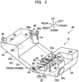
- FIG. 3 a perspective view of the fuel tank unit 30 viewed from the obliquely right front side of the vehicle body 1 according to the first embodiment is illustrated.
- the first tube 41 is connected so as to be able to supply the fuel 9 to the sucking-out member (discharge member) 49 provided to penetrate the partition plate 36 of the second storage tank 34.
- This sucking-out member 49 is a hollow tubular member extending to the center in the front-rear direction of the vehicle body 1 from the partition plate 36, in other words, forward, and is provided with an opening (discharge opening) 49a at an end on the front side.
- a fuel retaining member (stored fluid retaining part) 52 is provided near the partition plate 36 of the second storage tank 34.
- This fuel retaining member 52 includes a front wall (wall part) 52a and side walls (wall parts) 52b.
- the front wall 52a is formed to extend upward from a bottom 34d of the second storage tank 34 such that an upper end is located above an opening 49a of the sucking-out member 49.
- the side walls 52b are formed so as to extend upward from the bottom 34d of the second storage tank 34 similarly to the front wall 52a, have upper ends formed to be inclined to the bottom 34d side from an upper end of the front wall 52a toward the rear side in the front-rear direction of the vehicle body 1, and two side walls 52b are disposed at right and left ends of the front wall 52a. That is, the front wall 52a and the side walls 52b are disposed so as to surround the front side and the sides in the right-left direction of the opening 49a of the sucking-out member 49.
- the first tubular member 60 is a hollow tubular member having a first end opened on the partition plate 36 so as to enable the fuel 9 to flow from the first storage tank 32, and a second end extending toward the center in the front-rear direction of the vehicle body 1 to penetrate the front wall 52a of the fuel retaining member 52.
- An opening (hollow tube opening) 62 opened so as to enable the fuel 9 to flow through the second storage tank 34 is provided in the second end of this first tubular member 60.
- This opening 62 is provided on the side close to the center in the front-rear direction of the vehicle body 1 with respect to the opening 49a of the sucking-out member 49.
- each of the second tubular members 64 is a hollow tubular member having a first end provided on the partition plate 36 so as to enable the fuel 9 to flow from the first storage tank 32, and a second end extending toward the front side of the vehicle body 1 to penetrate the front wall 52a of the fuel retaining member 52, and having a smaller diameter than the first tubular member 60.
- An opening (hollow tube opening) 66 opened so as to enable the fuel 9 to flow through the second storage tank 34 is provided on the second end of this second tubular member 64. This opening 66 is provided on the front side with respect to the opening 49a of the sucking-out member 49.
- the two second tubular members 64 are disposed side by side on the left of the vehicle body 1 that is the direction separated from the oil filling port 38 compared to the first tubular member 60.
- the first tubular member 60 has the larger inner diameter than the second tubular members 64, and therefore a circulation possible amount of the fuel 9 per predetermined time can be increased compared to the second tubular members 64. Additionally, the first tubular member 60 is closer to the oil filling port 38 than the second tubular members 64, and therefore the fuel 9 replenished from the oil filling port 38 can be satisfactorily replenished to the second storage tank 34.
- FIG. 4 an explanatory diagram illustrating a state of the fuel 9 when the vehicle body 1 is located on a flat ground is illustrated.
- the fuel 9 is supplied from the oil filling port 38 to the first storage tank 32 of the fuel tank 31, the fuel 9 is supplied to the second storage tank 34 through the first tubular member 60 and the second tubular members 64. More specifically, the fuel 9 supplied to the rear storage tank 32a of the first storage tank 32 flows downward along the lower surface 32c by gravity, and passes through the center storage tank 33 to reach the partition plate 36.
- the first tubular member 60 and the second tubular members 64 are provided in the partition plate 36 so as to enable the fuel 9 to flow through the first tubular member 60 and the second tubular members 64, and therefore the fuel 9 passes through the partition plate 36, the first tubular member 60 and the second tubular members 64 from the center storage tank 33 to be supplied to the second storage tank 34.
- the fuel tank 31 can supply the fuel 9 from the sucking-out member 49 to the engine 10 through the filter device 46 and the pump 48.
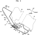
- FIG. 5 an explanatory diagram illustrating a state of the fuel 9 when the vehicle body is inclined at a predetermined angle such that a front part of the vehicle body 1 lowers is illustrated.
- the fuel 9 is biased to be stored on the front side in the front-rear direction of the vehicle body 1 of the second storage tank 34, and in the fuel retaining member 52. More specifically, the fuel 9 stored in the first storage tank 32 and the second storage tank 34 flows from the center storage tank 33 toward the front side in the front-rear direction of the vehicle body 1 of the second storage tank 34 through the first tubular member 60 and the second tubular members 64 by gravity.
- a part of the fuel 9 stored in the second storage tank 34 is prevented from flowing from the center storage tank 33 toward the front side in the front-rear direction of the vehicle body 1 of the second storage tank 34 by the fuel retaining member 52, and stored in the fuel retaining member 52.
- the fuel 9 is stored in the fuel retaining member 52, so that the fuel tank 31 can supply the fuel 9 from the sucking-out member 49 to the engine 10 through the filter device 46 and the pump 48.
- FIG. 6 an explanatory diagram illustrating a state of the fuel 9 when the vehicle body 1 is inclined at the predetermined angle such that the front part of the vehicle body 1 rises is illustrated.
- the fuel 9 is biased to be stored near the lower surface 32c of the first storage tank 32, and on the rear side in the front-rear direction of the vehicle body 1 of the second storage tank 34. More specifically, the fuel 9 stored in the second storage tank 34 flows from the center storage tank 33 toward the rear side in the front-rear direction of the vehicle body 1 of the second storage tank 34 through the first tubular member 60 and the second tubular members 64 by gravity.
- the first tubular member 60 and the second tubular members 64 extend and open toward the front side of the vehicle body 1 from the partition plate 36, so that the fuel 9 below the opening 62 and the openings 66 of the first tubular member 60 and the second tubular members 64 as viewed in the gravity direction, out of the fuel 9 stored in the second storage tank 34, is biased to be stored on the rear side in the front-rear direction of the vehicle body 1 of the second storage tank 34 without flowing toward the first storage tank 32.
- first tubular member 60 and the second tubular members 64 extend toward the front side of the vehicle body 1 from the partition plate 36, so that when the vehicle body 1 is inclined at the predetermined angle such that the front part of the vehicle body 1 rises, the fuel tank 31 can store the fuel 9 on the rear side in the front-rear direction of the vehicle body 1 of the second storage tank 34, and therefore it is possible to supply the fuel 9 from the sucking-out member 49 to the engine 10 through the filter device 46 and the pump 48.
- the first end of the fourth tube 44 is connected to the second storage tank 34 from the partition plate 36, so that the fuel 9 that is not used for combustion in the engine 10 and remains returns to the second storage tank 34 through the fourth tube 44, and therefore even when the vehicle body 1 is inclined at the predetermined angle such that the front part of the vehicle body 1 rises, it is possible to store the fuel 9 on the rear side in the front-rear direction of the vehicle body 1 of the second storage tank 34.
- the fuel tank 31 can supply the fuel 9 to the engine 10.
- the work vehicle according to the first embodiment is the work vehicle including the tank formed so as to extend from the rear part of the vehicle body 1 toward the center in the front-rear direction of the vehicle body 1,
- the fuel tank 31 has the first storage tank 32 that is located on the rear side of the vehicle body 1, and stores the fuel 9, the second storage tank 34 located on the side close to the center in the front-rear direction of the vehicle body 1, and stores stored fluid
- the partition plate 36 that separates the first storage tank 32 and the second storage tank 34, and the sucking-out member 49 that has the opening 49a extending and opened inside the second storage tank 34, and discharges the fuel 9 stored in the second storage tank 34 from the second storage tank 34
- the first tubular member 60 and the second tubular members 64 that have first ends communicated with the first storage tank 32 through the partition plate 36 so as to enable the fuel 9 to flow, and have the second ends having the opening 62 and the openings 66 extending and opened toward the center in the front-rear direction of the vehicle body 1 inside the second storage tank 34, and the opening
- the partition plate 36 that separates the first storage tank 32 and the second storage tank 34 is provided in the fuel tank 31, the first tubular member 60 and the second tubular members 64 having the first ends opened and provided in the partition plate 36, and the second ends having the opening 62 and the openings 66 on the side close to the center in the front-rear direction of the vehicle body 1 with respect to the opening 49a are provided in the second storage tank 34, and therefore, even in a case where the fuel 9 is biased to the rear side of the fuel tank 31, for example, even when the vehicle body 1 climbs a road surface inclined at the predetermined angle, the fuel 9 stored in the second storage tank 34 is stored on the lower side in the gravity direction with respect to the opening 62 provided in the second end of the first tubular member 60, and does not flow through the first storage tank 32, so that the fuel 9 can be discharged from the second storage tank 34 through the opening 49a of the sucking-out member 49 regardless of the inclination angle of the vehicle body 1.
- the fuel tank 31 is a tank that stores the fuel 9 to be supplied to the engine 10, and therefore even in a case where the fuel 9 is biased to the opposite side to the central side of the fuel tank 31 viewed in the front-rear direction of the vehicle body 1, for example, even when the vehicle body 1 climbs a road surface inclined at the predetermined angle, the fuel 9 is supplied to the engine 10, and the vehicle body 1 can climb.
- the fuel retaining member 52 that is provided inside the second storage tank 34 so as to surround the opening 49a by the front wall 52a and the side walls 52b from the center in the front-rear direction of the vehicle body 1 and the left and right sides, and that has the front wall 52a and the side walls 52b extending upward in the vertical direction of the vehicle body 1 with respect to the opening 49a from the bottom of the second storage tank 34 is provided, and therefore even in a case where the fuel 9 is biased to the side close to the center as viewed in the front-rear direction of the vehicle body 1 in the fuel tank 31, for example, even when the vehicle body 1 descends a road surface inclined at the predetermined angle, the fuel 9 is stored in the fuel retaining member 52, and therefore the fuel 9 can be discharged from the second storage tank 34 through the sucking-out member 49.
- the first tubular member 60 and the second tubular members 64 extend through the front wall 52a of the fuel retaining member 52, and the opening 62 and the openings 66 are located on the side close to the center in the front-rear direction of the vehicle body 1 with respect to the fuel retaining member 52, and therefore the second ends of the first tubular member 60 and the second tubular members 64 extend toward the center in the front-rear direction of the vehicle body 1 while the fuel retaining member 52 is disposed in the second storage tank 34, and the opening 62 and the openings 66 can be provided on the side close to the center in the front-rear direction of the vehicle body 1.
- the oil filling port 38 for supplying the fuel 9 to the first storage tank 32 is provided, and the first tubular member 60 closest to the oil filling port 38, out of the first tubular member 60 and the second tubular members 64, has the largest inner diameter, and therefore when the fuel 9 is supplied from the oil filling port 38 to the fuel tank 31, the fuel 9 can be satisfactorily supplied to the second storage tank 34.
- the fourth tube 44 for returning, to the second storage tank 34, a part or all of the fuel 9 discharged from the sucking-out member 49 is provided, and therefore even in a case where the fuel 9 is biased to the rear side of the fuel tank 31, for example, even when the vehicle body 1 climbs a road surface inclined at the predetermined angle, the fuel 9 returned to the second storage tank 34 from the fourth tube 44 can be stored on the lower side in the gravity direction with respect to the opening 62 provided in the second end of the first tubular member 60.
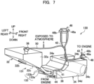
- FIG. 7 a perspective view of a fuel tank unit 130 viewed from the obliquely right rear side of a vehicle body 1 according to the second embodiment is illustrated.
- FIG. 8 a perspective view of the fuel tank unit 130 viewed from the obliquely right front side of the vehicle body 1 according to the second embodiment is illustrated.
- a fuel tank 131 according to the second embodiment includes a piping part (piping member) 133, in place of the center storage tank 33 according to the first embodiment.
- the piping part 133 includes a first pipe 133a and second pipes 133b.
- the first pipe 133a is a flexible pipe having a first end connected to an end on the rear side of a first tubular member 60 so as to enable the fuel 9 to flow, and a second end connected to a rear storage tank 32a so as to enable the fuel 9 to flow.
- Each of the second pipes 133b is a flexible pipe having a first end connected to an end on the rear side of a second tubular member 64 so as to enable the fuel 9 to flow, and a second end connected to the rear storage tank 32a so as to enable the fuel 9 to flow, similarly to the first pipe 133a.
- the two second tubular members 64 are provided in a second storage tank 34, and therefore these two second pipes 133b are connected to the respective second tubular members 64.
- the piping part 133 is provided, so that a fuel tank 131 is divided into a first storage tank 32 and the second storage tank 34.
- the first storage tank 32 and the second storage tank 34 are connected by the piping part 133 so as to enable the fuel 9 to flow.
- the fuel tank 131 is divided into the first storage tank 32 and the second storage tank 34, so that an engine 10 or a cooling device 20 can be maintained from a lower side of the an engine 10 or the cooling device 20 disposed above the fuel tank.
- the fuel tank 131 is divided into the first storage tank 32 and the second storage tank 34, and has the piping part 133 having a first end connected to the first tubular member 60 and the second tubular members 64 so as to enable the fuel 9 to flow, and a second end connected to the first storage tank 32 so as to enable the fuel 9 to flow.
- the fuel tank 131 is divided into the first storage tank 32 and the second storage tank 34, and the fuel 9 can flow through the first storage tank 32 and the second storage tank 34 through the piping part 133, and therefore for example, maintain of the engine 10 disposed above the fuel tank 131 can be performed from the fuel tank 131 side while the fuel 9 can flow between the first storage tank 32 and the second storage tank 34.
- the fuel tank 31 for storing the fuel 9, formed so as to extend from the rear part of the vehicle body 1 toward the central part of the vehicle body 1 is described.
- the fuel tank 31 may extend from the front part of the vehicle body 1 toward the central part of the vehicle body 1, or may be a water tank for storing water.
- the work vehicle is described as an earthwork vibration roller which is one of rolling machines in the embodiments, but the work vehicle may be a tire roller that compacts asphalt before solidification.
Landscapes
- Engineering & Computer Science (AREA)
- Chemical & Material Sciences (AREA)
- Mechanical Engineering (AREA)
- Combustion & Propulsion (AREA)
- General Engineering & Computer Science (AREA)
- Life Sciences & Earth Sciences (AREA)
- Sustainable Development (AREA)
- Sustainable Energy (AREA)
- Transportation (AREA)
- Structural Engineering (AREA)
- Civil Engineering (AREA)
- Architecture (AREA)
- Mining & Mineral Resources (AREA)
- Cooling, Air Intake And Gas Exhaust, And Fuel Tank Arrangements In Propulsion Units (AREA)
- Road Paving Machines (AREA)
Description
- The present invention relates to a work vehicle, and particularly to a technology for improving supply performance of fuel to an internal combustion engine mounted on a work vehicle.
- Generally, in road pavement work, an earthwork vibration roller is used in order to equalize flatness of the ground before construction of asphalt.
- This earthwork vibration roller is mounted with an engine and a fuel tank on a rear part thereof. When the earthwork vibration roller climbs, a vehicle body inclines in the front-rear direction, and therefore when fuel stored in the fuel tank is less, the fuel is biased to the rear side in the front-rear direction of the inside of the fuel tank.
- Thus, when the fuel is biased to the rear side in the front-rear direction of the inside of the fuel tank, for example, in a case where an inlet for supplying the fuel from the fuel tank to the engine is located at the center in the front-rear direction of the fuel tank, there is a possibility that a motor which feeds the fuel to the engine cannot suck the fuel.
- A technology for retaining a part of the fuel near the inlet at the time of inclination by providing a retaining part inside the fuel tank is developed (Patent Document 1).
- Patent Document 1: Japanese Patent Laid-Open No.
- However, in the technology disclosed in the aforementioned Patent Document 1, an amount of the fuel retained near the inlet is reduced depending on the inclination angle, and therefore there is room for further improvement.
DE 10 2014 202361 A1 discloses a work vehicle according to the preamble of claim 1. - The present invention has been made in view of such a problem, and an object of the present invention is to provide a work vehicle including a tank capable of supplying fuel to an internal combustion engine regardless of the inclination angle of a work vehicle inclined in the front-rear direction in a case where stored fluid is fuel of an internal combustion engine mounted on the work vehicle.
- The above cited problem is solved in accordance with the appended claims. In particular, a work vehicle including a tank formed so as to extend from a front part or a rear part of a vehicle body toward a center in a front-rear direction of the vehicle body, wherein the tank includes: a first storage tank located on a front side or a rear side of the vehicle body, and stores stored fluid; a second storage tank located on a side close to the center in the front-rear direction of the vehicle body, and stores the stored fluid; a partition part that separates the first storage tank and the second storage tank; and a discharge member that has a discharge opening extending and opened inside the second storage tank, and discharges, from the second storage tank, the stored fluid stored in the second storage tank; characterized in that the tank further includes a hollow tube member that has a first end communicated with the first storage tank through the partition part so as to enable the stored fluid to flow, and a second end having a hollow tube opening extending and opened toward the center in the front-rear direction of the vehicle body inside the second storage tank, wherein the hollow tube opening of the hollow tube member is located on the side close to the center in the front-rear direction of the vehicle body with respect to the discharge opening of the discharge member.
- According to a work vehicle of the present invention, in a case where stored fluid is fuel for an internal combustion engine mounted on the work vehicle, a tank can supply the fuel to the internal combustion engine regardless of the inclination angle of the work vehicle inclined in the front-rear direction.
-
-
FIG. 1 is a side view of a rolling machine mounted with a fuel tank according to the present invention. -
FIG. 2 is a perspective view of a fuel tank unit viewed from the obliquely right rear side of a rolling machine according to a first embodiment. -
FIG. 3 is a perspective view of the fuel tank unit viewed from the obliquely right front side of the rolling machine according to the first embodiment. -
FIG. 4 is an explanatory diagram illustrating a state of fuel when the rolling machine is located on a flat ground. -
FIG. 5 is an explanatory diagram illustrating a state of fuel when the rolling machine is inclined at a predetermined angle such that a front part of the rolling machine lowers. -
FIG. 6 is an explanatory diagram illustrating a state of fuel when the rolling machine is inclined at a predetermined angle such that the front part of the rolling machine rises. -
FIG. 7 is a perspective view of a fuel tank unit viewed from the obliquely right rear side of a rolling machine according to a second embodiment. -
FIG. 8 is a perspective view of the fuel tank unit viewed from the obliquely right front side of the rolling machine according to the second embodiment. - Hereinafter, an embodiment of the present invention will be described with reference to the drawings.
- Referring to
FIG. 1 , a side view of a vehicle body 1 of a rolling machine (work vehicle) mounted with a tank according to the present invention is illustrated. The vehicle body 1 is a so-called earthwork vibration roller having front wheels 3 which are iron wheels, and capable of compacting the ground before construction of asphalt by vibrating the front wheels 3 by an eccentric weight (not illustrated) provided in the front wheels 3 while moving forward and rearward the vehicle body 1 by driving rubberrear wheels 5, for example. This vehicle body 1 is mounted with an engine (internal combustion engine) 10, acooling device 20 and afuel tank unit 30. - The
engine 10 is an internal combustion engine that burns fuel (stored fluid) 9 supplied from thefuel tank unit 30 to generate driving force, and is mounted on the front side with respect to the center of anengine room 7 provided in a rear part in the front-rear direction of the vehicle body 1. Thecooling device 20 is a so-called heat exchanger provided on the rear side in the front-rear direction of the vehicle body 1 with respect to theengine 10. Thecooling device 20 is connected to theengine 10 by a high-temperature pipe 22 and a low-temperature pipe 24 so as to enable cooling water to flow. More specifically, cooling water that flows through a water jacket (not illustrated) provided in theengine 10 is heated by heat generated by operation of anengine 10, and high-temperature cooling water flows through thecooling device 20 through the high-temperature pipe 22. This high-temperature cooling water is cooled by thecooling device 20 to flows through theengine 10 through the low-temperature pipe 24. Consequently, in theengine 10, excessive rise of the internal temperature is suppressed. - Referring to
FIG. 2 , a perspective view of thefuel tank unit 30 viewed from the obliquely right rear side of the vehicle body 1 according to the first embodiment is illustrated. - The
fuel tank unit 30 includes a fuel tank (tank) 31, afilter device 46, and apump 48. Thefuel tank 31 is, for example, a resin tank formed so as to extend toward the center as viewed in the front-rear direction of the vehicle body 1 from the rear side of thecooling device 20 that is the rear part of the vehicle body 1 to the lower side of thecooling device 20. - More specifically, the
fuel tank 31 includes afirst storage tank 32 located at a rear part of the vehicle body 1, and capable of storing thefuel 9, and asecond storage tank 34 located on the lower side of theengine 10 which is on the side close to a center with respect to thefirst storage tank 32 as viewed in the front-rear direction of the vehicle body 1, and capable of storing thefuel 9. Additionally, thefuel tank 31 includes a partition plate (partition part) 36 that separates thefirst storage tank 32 and thesecond storage tank 34, and includes a first tubular member (hollow tube member) 60 and a second tubular members (hollow tube members) 64. In thisfuel tank 31, one ends of abreather hose 50 are connected to an upper end surface of thefirst storage tank 32 and an upper end surface of thesecond storage tank 34. An upper part of thefirst storage tank 32 or an upper part of thesecond storage tank 34 sometimes has high pressure by volatilization of the storedfuel 9. Therefore, a canister (not illustrated) is provided in the other end of thebreather hose 50, and thefuel 9 volatilized from highpressure air generated in the upper part of thefirst storage tank 32 or the upper part of thesecond storage tank 34 can be extracted to be opened to the atmosphere. - The
first storage tank 32 includes arear storage tank 32a located on the rear side of thecooling device 20, and acenter storage tank 33 located on the lower side of thecooling device 20. In therear storage tank 32a, an oil filling port (replenishing port) 38 for supplying thefuel 9 to thefirst storage tank 32 is provided on the right in the right-left direction of the upper part. Thelower surface 32c of therear storage tank 32a is formed in a shape inclined at a predetermined angle so as to lower forward from a rear end to a front end as viewed from the right-left direction of the vehicle body 1. Afirst cleaning window 32b is provided in thelower surface 32c of thisrear storage tank 32a. Thefirst cleaning window 32b is a window for cleaning thefirst storage tank 32 when an operator wrongly supplies liquid medicine other than thefuel 9 such as a reducing agent from theoil filling port 38 to thefirst storage tank 32, for example. - The
center storage tank 33 extends toward thesecond storage tank 34 from therear storage tank 32a. Thiscenter storage tank 33 is formed in a shape in which an upper surface and a lower surface are each inclined at a predetermined angle from the rear end to the front end as viewed from a side surface of the vehicle body 1. - In the
second storage tank 34, arecess 34a for avoiding interference with thecooling device 20 is formed in a rear upper part, and agroove 34b for avoiding interference with theengine 10 is formed at a center in the right-left direction in a front upper part. Additionally, asecond cleaning window 34c is provided in a front end of thesecond storage tank 34. Thissecond cleaning window 34c is a window for cleaning thesecond storage tank 34 similarly to thefirst cleaning window 32b. - A
first tube 41 and a fourth tube (return part) 44 are connected to thesecond storage tank 34. Thefourth tube 44 has a first end connected to thepartition plate 36 so as to be able to supply thefuel 9 to thesecond storage tank 34, and a second end connected to theengine 10. Thefirst tube 41 has a first end connected to a sucking-outmember 49, described below, connected to thepartition plate 36 so as to enable thefuel 9 to flow through thesecond storage tank 34, and has a second end connected to thefilter device 46 so as to enable thefuel 9 to flow. Thefilter device 46 is a filter for removing fine dust included in thefuel 9, and the second end of thefirst tube 41 is connected to anintroduction part 46a so as to enable thefuel 9 to flow, and a first end of thesecond tube 42 is connected to adischarge part 46b so as to enable thefuel 9 to flow. - The
second tube 42 has the first end connected to thedischarge part 46b of thefilter device 46 so as to enable thefuel 9 to flow, and a second end connected to anintroduction part 48a of thepump 48 so as to enable thefuel 9 to flow. Thepump 48 is, for example, a trochoid type pump, sucks thefuel 9 from thesecond tube 42 through theintroduction part 48a, and discharges thefuel 9 to athird tube 43 connected to a first end of the pump so as to enable thefuel 9 to flow from adischarge part 48b. Thethird tube 43 has a first end connected to thedischarge part 48b of thepump 48 so as to enable thefuel 9 to flow, and a second end connected to theengine 10 so as to enable thefuel 9 to flow. Thus, thefuel 9 stored in thesecond storage tank 34 is introduced in thefilter device 46 through thefirst tube 41 to be purified, and thereafter is sucked in thepump 48 through thesecond tube 42, and is supplied to theengine 10 through thethird tube 43. - The
engine 10 operates by burning thefuel 9 supplied as described above. At this time,fuel 9 that is not used for combustion and remains, out of thefuel 9 supplied to theengine 10, returns to thesecond storage tank 34 through thefourth tube 44. - Referring to
FIG. 3 , a perspective view of thefuel tank unit 30 viewed from the obliquely right front side of the vehicle body 1 according to the first embodiment is illustrated. Thefirst tube 41 is connected so as to be able to supply thefuel 9 to the sucking-out member (discharge member) 49 provided to penetrate thepartition plate 36 of thesecond storage tank 34. This sucking-out member 49 is a hollow tubular member extending to the center in the front-rear direction of the vehicle body 1 from thepartition plate 36, in other words, forward, and is provided with an opening (discharge opening) 49a at an end on the front side. - A fuel retaining member (stored fluid retaining part) 52 is provided near the
partition plate 36 of thesecond storage tank 34. Thisfuel retaining member 52 includes a front wall (wall part) 52a and side walls (wall parts) 52b. Thefront wall 52a is formed to extend upward from a bottom 34d of thesecond storage tank 34 such that an upper end is located above anopening 49a of the sucking-out member 49. Theside walls 52b are formed so as to extend upward from the bottom 34d of thesecond storage tank 34 similarly to thefront wall 52a, have upper ends formed to be inclined to the bottom 34d side from an upper end of thefront wall 52a toward the rear side in the front-rear direction of the vehicle body 1, and twoside walls 52b are disposed at right and left ends of thefront wall 52a. That is, thefront wall 52a and theside walls 52b are disposed so as to surround the front side and the sides in the right-left direction of theopening 49a of the sucking-out member 49. - The first
tubular member 60 is a hollow tubular member having a first end opened on thepartition plate 36 so as to enable thefuel 9 to flow from thefirst storage tank 32, and a second end extending toward the center in the front-rear direction of the vehicle body 1 to penetrate thefront wall 52a of thefuel retaining member 52. An opening (hollow tube opening) 62 opened so as to enable thefuel 9 to flow through thesecond storage tank 34 is provided in the second end of this firsttubular member 60. Thisopening 62 is provided on the side close to the center in the front-rear direction of the vehicle body 1 with respect to theopening 49a of the sucking-out member 49. - Similarly to the first
tubular member 60, each of the secondtubular members 64 is a hollow tubular member having a first end provided on thepartition plate 36 so as to enable thefuel 9 to flow from thefirst storage tank 32, and a second end extending toward the front side of the vehicle body 1 to penetrate thefront wall 52a of thefuel retaining member 52, and having a smaller diameter than the firsttubular member 60. An opening (hollow tube opening) 66 opened so as to enable thefuel 9 to flow through thesecond storage tank 34 is provided on the second end of this secondtubular member 64. Thisopening 66 is provided on the front side with respect to theopening 49a of the sucking-out member 49. The two secondtubular members 64 are disposed side by side on the left of the vehicle body 1 that is the direction separated from theoil filling port 38 compared to the firsttubular member 60. - In other words, the first
tubular member 60 has the larger inner diameter than the secondtubular members 64, and therefore a circulation possible amount of thefuel 9 per predetermined time can be increased compared to the secondtubular members 64. Additionally, the firsttubular member 60 is closer to theoil filling port 38 than the secondtubular members 64, and therefore thefuel 9 replenished from theoil filling port 38 can be satisfactorily replenished to thesecond storage tank 34. - Referring to
FIG. 4 , an explanatory diagram illustrating a state of thefuel 9 when the vehicle body 1 is located on a flat ground is illustrated. - When the
fuel 9 is supplied from theoil filling port 38 to thefirst storage tank 32 of thefuel tank 31, thefuel 9 is supplied to thesecond storage tank 34 through the firsttubular member 60 and the secondtubular members 64. More specifically, thefuel 9 supplied to therear storage tank 32a of thefirst storage tank 32 flows downward along thelower surface 32c by gravity, and passes through thecenter storage tank 33 to reach thepartition plate 36. The firsttubular member 60 and the secondtubular members 64 are provided in thepartition plate 36 so as to enable thefuel 9 to flow through the firsttubular member 60 and the secondtubular members 64, and therefore thefuel 9 passes through thepartition plate 36, the firsttubular member 60 and the secondtubular members 64 from thecenter storage tank 33 to be supplied to thesecond storage tank 34. - Consequently, when the vehicle body 1 is located on the flat ground, the
fuel tank 31 can supply thefuel 9 from the sucking-out member 49 to theengine 10 through thefilter device 46 and thepump 48. - Referring to
FIG. 5 , an explanatory diagram illustrating a state of thefuel 9 when the vehicle body is inclined at a predetermined angle such that a front part of the vehicle body 1 lowers is illustrated. - When the vehicle body 1 is inclined at the predetermined angle such that the front part of the vehicle body 1 lowers, the
fuel 9 is biased to be stored on the front side in the front-rear direction of the vehicle body 1 of thesecond storage tank 34, and in thefuel retaining member 52. More specifically, thefuel 9 stored in thefirst storage tank 32 and thesecond storage tank 34 flows from thecenter storage tank 33 toward the front side in the front-rear direction of the vehicle body 1 of thesecond storage tank 34 through the firsttubular member 60 and the secondtubular members 64 by gravity. On the other hand, a part of thefuel 9 stored in thesecond storage tank 34 is prevented from flowing from thecenter storage tank 33 toward the front side in the front-rear direction of the vehicle body 1 of thesecond storage tank 34 by thefuel retaining member 52, and stored in thefuel retaining member 52. - Consequently, when the vehicle body 1 is inclined at the predetermined angle such that the front part of the vehicle body 1 lowers, the
fuel 9 is stored in thefuel retaining member 52, so that thefuel tank 31 can supply thefuel 9 from the sucking-out member 49 to theengine 10 through thefilter device 46 and thepump 48. - Referring to
FIG. 6 , an explanatory diagram illustrating a state of thefuel 9 when the vehicle body 1 is inclined at the predetermined angle such that the front part of the vehicle body 1 rises is illustrated. - When the vehicle body 1 is inclined at the predetermined angle such that the front part of the vehicle body 1 rises, the
fuel 9 is biased to be stored near thelower surface 32c of thefirst storage tank 32, and on the rear side in the front-rear direction of the vehicle body 1 of thesecond storage tank 34. More specifically, thefuel 9 stored in thesecond storage tank 34 flows from thecenter storage tank 33 toward the rear side in the front-rear direction of the vehicle body 1 of thesecond storage tank 34 through the firsttubular member 60 and the secondtubular members 64 by gravity. At this time, the firsttubular member 60 and the secondtubular members 64 extend and open toward the front side of the vehicle body 1 from thepartition plate 36, so that thefuel 9 below theopening 62 and theopenings 66 of the firsttubular member 60 and the secondtubular members 64 as viewed in the gravity direction, out of thefuel 9 stored in thesecond storage tank 34, is biased to be stored on the rear side in the front-rear direction of the vehicle body 1 of thesecond storage tank 34 without flowing toward thefirst storage tank 32. - Thus, the first
tubular member 60 and the secondtubular members 64 extend toward the front side of the vehicle body 1 from thepartition plate 36, so that when the vehicle body 1 is inclined at the predetermined angle such that the front part of the vehicle body 1 rises, thefuel tank 31 can store thefuel 9 on the rear side in the front-rear direction of the vehicle body 1 of thesecond storage tank 34, and therefore it is possible to supply thefuel 9 from the sucking-out member 49 to theengine 10 through thefilter device 46 and thepump 48. - The first end of the
fourth tube 44 is connected to thesecond storage tank 34 from thepartition plate 36, so that thefuel 9 that is not used for combustion in theengine 10 and remains returns to thesecond storage tank 34 through thefourth tube 44, and therefore even when the vehicle body 1 is inclined at the predetermined angle such that the front part of the vehicle body 1 rises, it is possible to store thefuel 9 on the rear side in the front-rear direction of the vehicle body 1 of thesecond storage tank 34. - With such a configuration, even in any of a state in which the vehicle body 1 is located on the flat ground, a state in which the vehicle body 1 is inclined at the predetermined angle such that the front part lowers, and a state in which the vehicle body 1 is inclined at the predetermined angle such that the front part rises, the
fuel tank 31 can supply thefuel 9 to theengine 10. - As described above, the work vehicle according to the first embodiment is the work vehicle including the tank formed so as to extend from the rear part of the vehicle body 1 toward the center in the front-rear direction of the vehicle body 1, the fuel tank 31 has the first storage tank 32 that is located on the rear side of the vehicle body 1, and stores the fuel 9, the second storage tank 34 located on the side close to the center in the front-rear direction of the vehicle body 1, and stores stored fluid, the partition plate 36 that separates the first storage tank 32 and the second storage tank 34, and the sucking-out member 49 that has the opening 49a extending and opened inside the second storage tank 34, and discharges the fuel 9 stored in the second storage tank 34 from the second storage tank 34, and the first tubular member 60 and the second tubular members 64 that have first ends communicated with the first storage tank 32 through the partition plate 36 so as to enable the fuel 9 to flow, and have the second ends having the opening 62 and the openings 66 extending and opened toward the center in the front-rear direction of the vehicle body 1 inside the second storage tank 34, and the opening 62 and the openings 66 of the first tubular member 60 and the second tubular members 64 are located on the side close to the center in the front-rear direction of the vehicle body 1 with respect to the opening 49a of the sucking-out member 49.
- Therefore, the
partition plate 36 that separates thefirst storage tank 32 and thesecond storage tank 34 is provided in thefuel tank 31, the firsttubular member 60 and the secondtubular members 64 having the first ends opened and provided in thepartition plate 36, and the second ends having theopening 62 and theopenings 66 on the side close to the center in the front-rear direction of the vehicle body 1 with respect to theopening 49a are provided in thesecond storage tank 34, and therefore, even in a case where thefuel 9 is biased to the rear side of thefuel tank 31, for example, even when the vehicle body 1 climbs a road surface inclined at the predetermined angle, thefuel 9 stored in thesecond storage tank 34 is stored on the lower side in the gravity direction with respect to theopening 62 provided in the second end of the firsttubular member 60, and does not flow through thefirst storage tank 32, so that thefuel 9 can be discharged from thesecond storage tank 34 through theopening 49a of the sucking-out member 49 regardless of the inclination angle of the vehicle body 1. - Particularly, the
fuel tank 31 is a tank that stores thefuel 9 to be supplied to theengine 10, and therefore even in a case where thefuel 9 is biased to the opposite side to the central side of thefuel tank 31 viewed in the front-rear direction of the vehicle body 1, for example, even when the vehicle body 1 climbs a road surface inclined at the predetermined angle, thefuel 9 is supplied to theengine 10, and the vehicle body 1 can climb. - The
fuel retaining member 52 that is provided inside thesecond storage tank 34 so as to surround theopening 49a by thefront wall 52a and theside walls 52b from the center in the front-rear direction of the vehicle body 1 and the left and right sides, and that has thefront wall 52a and theside walls 52b extending upward in the vertical direction of the vehicle body 1 with respect to theopening 49a from the bottom of thesecond storage tank 34 is provided, and therefore even in a case where thefuel 9 is biased to the side close to the center as viewed in the front-rear direction of the vehicle body 1 in thefuel tank 31, for example, even when the vehicle body 1 descends a road surface inclined at the predetermined angle, thefuel 9 is stored in thefuel retaining member 52, and therefore thefuel 9 can be discharged from thesecond storage tank 34 through the sucking-out member 49. - The first
tubular member 60 and the secondtubular members 64 extend through thefront wall 52a of thefuel retaining member 52, and theopening 62 and theopenings 66 are located on the side close to the center in the front-rear direction of the vehicle body 1 with respect to thefuel retaining member 52, and therefore the second ends of the firsttubular member 60 and the secondtubular members 64 extend toward the center in the front-rear direction of the vehicle body 1 while thefuel retaining member 52 is disposed in thesecond storage tank 34, and theopening 62 and theopenings 66 can be provided on the side close to the center in the front-rear direction of the vehicle body 1. - The
oil filling port 38 for supplying thefuel 9 to thefirst storage tank 32 is provided, and the firsttubular member 60 closest to theoil filling port 38, out of the firsttubular member 60 and the secondtubular members 64, has the largest inner diameter, and therefore when thefuel 9 is supplied from theoil filling port 38 to thefuel tank 31, thefuel 9 can be satisfactorily supplied to thesecond storage tank 34. - The
fourth tube 44 for returning, to thesecond storage tank 34, a part or all of thefuel 9 discharged from the sucking-out member 49 is provided, and therefore even in a case where thefuel 9 is biased to the rear side of thefuel tank 31, for example, even when the vehicle body 1 climbs a road surface inclined at the predetermined angle, thefuel 9 returned to thesecond storage tank 34 from thefourth tube 44 can be stored on the lower side in the gravity direction with respect to theopening 62 provided in the second end of the firsttubular member 60. - Hereinafter, a second embodiment will be described with reference to
FIGS. 7 and8 . Description of a configuration common with the configuration of the aforementioned first embodiment will be omitted, and different portions from the first embodiment will be herein described. - Referring to
FIG. 7 , a perspective view of afuel tank unit 130 viewed from the obliquely right rear side of a vehicle body 1 according to the second embodiment is illustrated. Referring toFIG. 8 , a perspective view of thefuel tank unit 130 viewed from the obliquely right front side of the vehicle body 1 according to the second embodiment is illustrated. - A
fuel tank 131 according to the second embodiment includes a piping part (piping member) 133, in place of thecenter storage tank 33 according to the first embodiment. - The piping
part 133 includes afirst pipe 133a andsecond pipes 133b. Thefirst pipe 133a is a flexible pipe having a first end connected to an end on the rear side of a firsttubular member 60 so as to enable thefuel 9 to flow, and a second end connected to arear storage tank 32a so as to enable thefuel 9 to flow. Each of thesecond pipes 133b is a flexible pipe having a first end connected to an end on the rear side of a secondtubular member 64 so as to enable thefuel 9 to flow, and a second end connected to therear storage tank 32a so as to enable thefuel 9 to flow, similarly to thefirst pipe 133a. The two secondtubular members 64 are provided in asecond storage tank 34, and therefore these twosecond pipes 133b are connected to the respective secondtubular members 64. - That is, the piping
part 133 is provided, so that afuel tank 131 is divided into afirst storage tank 32 and thesecond storage tank 34. Thefirst storage tank 32 and thesecond storage tank 34 are connected by the pipingpart 133 so as to enable thefuel 9 to flow. Thus, thefuel tank 131 is divided into thefirst storage tank 32 and thesecond storage tank 34, so that anengine 10 or acooling device 20 can be maintained from a lower side of the anengine 10 or thecooling device 20 disposed above the fuel tank. - As described above, in the work vehicle according to the second embodiment, the
fuel tank 131 is divided into thefirst storage tank 32 and thesecond storage tank 34, and has thepiping part 133 having a first end connected to the firsttubular member 60 and the secondtubular members 64 so as to enable thefuel 9 to flow, and a second end connected to thefirst storage tank 32 so as to enable thefuel 9 to flow. - Therefore, the
fuel tank 131 is divided into thefirst storage tank 32 and thesecond storage tank 34, and thefuel 9 can flow through thefirst storage tank 32 and thesecond storage tank 34 through the pipingpart 133, and therefore for example, maintain of theengine 10 disposed above thefuel tank 131 can be performed from thefuel tank 131 side while thefuel 9 can flow between thefirst storage tank 32 and thesecond storage tank 34. - The description of the work vehicle according to the present invention will be finished. The present invention is not limited to the aforementioned embodiments and can be changed without departing from the scope of the invention, defined only by the appended claims.
- For example, in this embodiment, the
fuel tank 31 for storing thefuel 9, formed so as to extend from the rear part of the vehicle body 1 toward the central part of the vehicle body 1 is described. However, thefuel tank 31 may extend from the front part of the vehicle body 1 toward the central part of the vehicle body 1, or may be a water tank for storing water. - The work vehicle is described as an earthwork vibration roller which is one of rolling machines in the embodiments, but the work vehicle may be a tire roller that compacts asphalt before solidification.
-
- 1
- vehicle body
- 9
- fuel (stored fluid)
- 10
- engine (internal combustion engine)
- 31, 131
- fuel tank (tank)
- 32
- first storage tank
- 34
- second storage tank
- 34d
- bottom
- 36
- partition plate (partition part)
- 38
- oil filling port (replenishing port)
- 44
- fourth tube (return part)
- 49
- sucking-out member (discharge member)
- 49a
- opening (discharge opening)
- 52
- fuel retaining member (stored fluid retaining part)
- 52a
- front wall (wall part)
- 52b
- side wall (wall part)
- 60
- first tubular member (hollow tube member)
- 62
- opening (hollow tube opening)
- 64
- second tubular member (hollow tube member)
- 66
- opening (hollow tube opening)
- 133
- piping part (piping member)
Claims (7)
- A work vehicle comprising a tank (31, 131) formed so as to extend from a front part or a rear part of a vehicle body toward a center in a front-rear direction of the vehicle body, wherein
the tank includes:a first storage tank (32) located on a front side or a rear side of the vehicle body, and stores stored fluid (9);a second storage tank (34) located on a side close to the center with respect to the first storage tank (32) as viewed in the front-rear direction of the vehicle body, and stores the stored fluid;a partition part (36) that separates the first storage tank and the second storage tank;a discharge member (49) that has a discharge opening (49a) extending and opened inside the second storage tank, and discharges, from the second storage tank, the stored fluid stored in the second storage tank; characterized in thatthe tank further includes a hollow tube member (60, 64) that has a first end communicated with the first storage tank through the partition part so as to enable the stored fluid to flow, and a second end having a hollow tube opening (62, 66) extending and opened toward the center in the front-rear direction of the vehicle body inside the second storage tank, whereinthe hollow tube opening of the hollow tube member is located on the side close to the center in the front-rear direction of the vehicle body with respect to the discharge opening of the discharge member. - The work vehicle according to claim 1, wherein
a stored fluid retaining part (52) that is provided in the second storage tank so as to surround the discharge opening by a wall part (52a, 52b) from the center in the front-rear direction of the vehicle body, and right and left sides, and that has the wall part extending upward in a vertical direction of the vehicle body with respect to the discharge opening from a bottom of the second storage tank is provided. - The work vehicle according to claim 2, whereinthe hollow tube member (60, 64) extends through the wall part of the stored fluid retaining part, andthe hollow tube opening (62, 66) is located on the side close to the center in the front-rear direction of the vehicle body with respect to the stored fluid retaining part (52).
- The work vehicle according to claim 1, whereina replenishing port (38) for supplying the stored fluid to the first storage tank is provided,the hollow tube member is composed of a plurality of the hollow tube members (60, 64), andthe hollow tube member (60) disposed closest to the replenishing port, out of the plurality of hollow tube members, has the largest inner diameter.
- The work vehicle according to claim 1, wherein
a return part (44) that returns, to the second storage tank, a part or all of the stored fluid discharged from the discharge member is provided. - The work vehicle according to claim 1, whereinthe vehicle body is mounted with an internal combustion (10) engine that generates driving force, andthe stored fluid (9) is fuel for the internal combustion engine.
- The work vehicle according to claim 1, whereinthe tank (131) is divided to the first storage tank (32) and the second storage tank (34), anda piping member (133) having a first end connected to the hollow tube member so as to enable the stored fluid to flow, and a second end connected to the first storage tank so as to enable the stored fluid to flow is provided.
Applications Claiming Priority (2)
| Application Number | Priority Date | Filing Date | Title |
|---|---|---|---|
| JP2018056736A JP6708685B2 (en) | 2018-03-23 | 2018-03-23 | Work vehicle tank |
| PCT/JP2019/005596 WO2019181306A1 (en) | 2018-03-23 | 2019-02-15 | Work vehicle |
Publications (3)
| Publication Number | Publication Date |
|---|---|
| EP3769992A1 EP3769992A1 (en) | 2021-01-27 |
| EP3769992A4 EP3769992A4 (en) | 2022-01-05 |
| EP3769992B1 true EP3769992B1 (en) | 2024-01-24 |
Family
ID=67987693
Family Applications (1)
| Application Number | Title | Priority Date | Filing Date |
|---|---|---|---|
| EP19770566.8A Active EP3769992B1 (en) | 2018-03-23 | 2019-02-15 | Work vehicle |
Country Status (4)
| Country | Link |
|---|---|
| US (1) | US11325465B2 (en) |
| EP (1) | EP3769992B1 (en) |
| JP (1) | JP6708685B2 (en) |
| WO (1) | WO2019181306A1 (en) |
Families Citing this family (3)
| Publication number | Priority date | Publication date | Assignee | Title |
|---|---|---|---|---|
| JP6752248B2 (en) * | 2018-03-23 | 2020-09-09 | 日立建機株式会社 | Work vehicle |
| DE102022113204A1 (en) * | 2022-05-25 | 2023-11-30 | Hamm Ag | Tillage roller |
| GB2638958A (en) * | 2024-02-28 | 2025-09-10 | Caterpillar Inc | Slewing work machine with primary and secondary fuel tanks and detachable counterweight mount |
Family Cites Families (52)
| Publication number | Priority date | Publication date | Assignee | Title |
|---|---|---|---|---|
| US2530819A (en) | 1947-05-27 | 1950-11-21 | Jolene Corp | Saddle tank for motor vehicles |
| GB842590A (en) | 1958-01-31 | 1960-07-27 | Marshall Sons And Company Ltd | Improvements in self-propelling road rollers |
| US3311183A (en) | 1963-05-13 | 1967-03-28 | Massey Ferguson Inc | Tractor having saddle gas tanks |
| US3586363A (en) | 1969-09-18 | 1971-06-22 | Gary M Wolverton | Expanded fuel supply system for pickup trucks |
| US4288086A (en) | 1980-01-22 | 1981-09-08 | International Harvester Company | Fuel tank arrangement for a tractor |
| US4852892A (en) | 1984-08-07 | 1989-08-01 | Reid Richard M | Convenient dual fuel tank system |
| JPS61287822A (en) | 1985-06-17 | 1986-12-18 | Nissan Shatai Co Ltd | Fuel tank for vehicle |
| US4664144A (en) | 1986-04-14 | 1987-05-12 | Deere & Company | Fuel recovery system for dual tanks |
| JPH0776231A (en) * | 1993-06-18 | 1995-03-20 | Seirei Ind Co Ltd | Fuel tank of traveling agricultural machine |
| US5658013A (en) | 1995-09-20 | 1997-08-19 | The Babcock & Wilcox Company | Fuel tank for vehicles for holding and dispensing both a liquid and gaseous fuel therein |
| JPH1035299A (en) | 1996-07-22 | 1998-02-10 | Kubota Corp | Work tank fuel tank structure |
| JP3199643B2 (en) * | 1996-08-29 | 2001-08-20 | 大淀小松株式会社 | Vehicle with movable center of gravity |
| US5983932A (en) | 1997-10-29 | 1999-11-16 | General Motors Corporation | Dual tank fuel system |
| JPH11245677A (en) * | 1998-03-05 | 1999-09-14 | Hitachi Constr Mach Co Ltd | Fuel tank device for construction machine |
| JP2000142127A (en) * | 1998-11-10 | 2000-05-23 | Hitachi Constr Mach Co Ltd | Fuel tank device of construction machine |
| JP4116173B2 (en) | 1998-12-25 | 2008-07-09 | 株式会社加藤製作所 | Construction machinery fuel tank |
| JP3735489B2 (en) | 1999-06-29 | 2006-01-18 | 株式会社クボタ | Fuel supply device for engine for work equipment |
| US6550811B1 (en) | 2000-06-30 | 2003-04-22 | Caterpillar Inc | Dual fuel tank system for an earthmoving vehicle |
| JP2002059750A (en) | 2000-08-21 | 2002-02-26 | Iseki & Co Ltd | Passenger farm work body |
| DE10055355C2 (en) * | 2000-11-08 | 2003-07-10 | Kautex Textron Gmbh & Co Kg | Fuel tank |
| KR100412593B1 (en) | 2001-05-03 | 2003-12-31 | 현대자동차주식회사 | Fuel stalling prevention device of sub-fuel tank as driving in slope way |
| KR100534789B1 (en) | 2003-10-24 | 2005-12-07 | 기아자동차주식회사 | Fuel tank system of vehicle |
| JP2006027316A (en) | 2004-07-12 | 2006-02-02 | Komatsu Ltd | Work vehicle |
| US7270209B2 (en) | 2004-08-10 | 2007-09-18 | General Motors Corporation | Modular fuel storage system for a vehicle |
| JP4418742B2 (en) | 2004-12-17 | 2010-02-24 | キャタピラージャパン株式会社 | Wheel loader |
| JP2006341719A (en) | 2005-06-09 | 2006-12-21 | Tcm Corp | Fuel tank of working vehicle |
| GB2434347A (en) | 2006-01-18 | 2007-07-25 | Cnh Uk Ltd | Auxiliary fuel tank system for agricultural vehicles |
| KR100772060B1 (en) | 2006-06-28 | 2007-11-01 | 볼보 컨스트럭션 이키프먼트 홀딩 스웨덴 에이비 | Fuel supply system for construction or forest heavy equipment |
| JP2008025207A (en) | 2006-07-21 | 2008-02-07 | Shin Caterpillar Mitsubishi Ltd | Fuel tank arrangement structure of wheel loader |
| JP4980936B2 (en) * | 2008-01-10 | 2012-07-18 | トヨタ自動車株式会社 | Fuel tank structure |
| BRPI0823369B1 (en) | 2008-12-12 | 2020-02-04 | Volvo Lastvagnar Ab | tank and vehicle layout with a tank layout |
| DE102011005275A1 (en) | 2011-03-09 | 2012-09-13 | Hamm Ag | Self-propelled construction equipment, in particular soil compactors |
| US10086694B2 (en) | 2011-09-16 | 2018-10-02 | Gaseous Fuel Systems, Corp. | Modification of an industrial vehicle to include a containment area and mounting assembly for an alternate fuel |
| EP2679430A1 (en) | 2012-06-27 | 2014-01-01 | Caterpillar Inc. | Fuel tanks for construction machines |
| EP2679429B9 (en) | 2012-06-27 | 2016-08-17 | Caterpillar Inc. | Construction machines and fuel tanks for construction machines |
| JP5941418B2 (en) | 2013-01-29 | 2016-06-29 | 日立建機株式会社 | Work vehicle |
| DE102013106962A1 (en) | 2013-07-03 | 2015-01-22 | CLAAS Tractor S.A.S | Agricultural vehicle |
| KR101641421B1 (en) * | 2014-01-31 | 2016-07-20 | 가부시끼 가이샤 구보다 | Work vehicle |
| DE102014202361B4 (en) * | 2014-02-10 | 2026-03-19 | Deere & Company | fuel tank system |
| US9207157B2 (en) | 2014-03-17 | 2015-12-08 | Caterpillar Paving Products Inc. | System and method for determining a state of compaction |
| JP6218674B2 (en) * | 2014-05-28 | 2017-10-25 | 株式会社クボタ | Work vehicle |
| JP6230515B2 (en) | 2014-09-26 | 2017-11-15 | 株式会社クボタ | Work vehicle |
| DE202014010518U1 (en) | 2014-12-18 | 2015-11-09 | Hamm Ag | Soil preparation machine, in particular soil compactor |
| US9517692B2 (en) * | 2014-12-30 | 2016-12-13 | Deere & Company | Tank with inverted sump |
| JP6495082B2 (en) | 2015-04-17 | 2019-04-03 | 日立建機株式会社 | Construction machinery |
| JP6588239B2 (en) | 2015-06-03 | 2019-10-09 | 日立建機株式会社 | Construction machinery |
| US20170113543A1 (en) | 2015-10-23 | 2017-04-27 | Caterpillar Paving Products Inc. | DEF Tank Constraint Using Flexible Medium |
| DE102015221366A1 (en) * | 2015-10-31 | 2017-05-04 | Ti Automotive Technology Center Gmbh | Saddle tank with slosh lock |
| KR101755895B1 (en) | 2015-11-24 | 2017-07-07 | 현대자동차주식회사 | Fuel auxiliary tank for flexible fuel vehicle |
| JP2017136875A (en) | 2016-02-01 | 2017-08-10 | 三菱マヒンドラ農機株式会社 | Working vehicle |
| JP6801997B2 (en) | 2016-08-02 | 2020-12-16 | ヤンマーパワーテクノロジー株式会社 | combine |
| JP7059154B2 (en) | 2018-09-21 | 2022-04-25 | 日立建機株式会社 | Rolling machine |
-
2018
- 2018-03-23 JP JP2018056736A patent/JP6708685B2/en active Active
-
2019
- 2019-02-15 EP EP19770566.8A patent/EP3769992B1/en active Active
- 2019-02-15 US US16/644,851 patent/US11325465B2/en active Active
- 2019-02-15 WO PCT/JP2019/005596 patent/WO2019181306A1/en not_active Ceased
Also Published As
| Publication number | Publication date |
|---|---|
| US20210070168A1 (en) | 2021-03-11 |
| EP3769992A4 (en) | 2022-01-05 |
| JP2019167003A (en) | 2019-10-03 |
| JP6708685B2 (en) | 2020-06-10 |
| WO2019181306A1 (en) | 2019-09-26 |
| US11325465B2 (en) | 2022-05-10 |
| EP3769992A1 (en) | 2021-01-27 |
Similar Documents
| Publication | Publication Date | Title |
|---|---|---|
| EP3769992B1 (en) | Work vehicle | |
| CN100436804C (en) | Fuel tank system | |
| EP3808967B1 (en) | Work vehicle | |
| JP2024544372A (en) | Circulation sump device for an electric drive unit of a vehicle - Patents.com | |
| EP3769993B1 (en) | Work vehicle | |
| JP2005163570A (en) | Lubricating device for internal combustion engine | |
| JP2011069246A (en) | Fuel supply device | |
| CA1091112A (en) | Radiator top tank with plural sump lines | |
| JP5701075B2 (en) | Cooling structure of hydraulic oil tank in work vehicle | |
| CN108473048A (en) | Fuel tank with additional reserve volume | |
| JP2009179226A (en) | Fuel tank structure | |
| KR102783939B1 (en) | Clutch of vehicles | |
| EP1775433A2 (en) | Oil filter unit and motorcycle including the oil filter unit | |
| JP2605169B2 (en) | Header tank used for engine cooling system | |
| EP1630378A1 (en) | Cooling system and internal combustion engine with the cooling system | |
| JPH09166023A (en) | Header tank used in engine cooler | |
| US20230059952A1 (en) | Work machine | |
| CN111911263B (en) | Vehicle oil supply mechanism | |
| JP2018105125A (en) | vehicle | |
| JP2015093546A (en) | Vehicle fuel tank | |
| JP2010151084A (en) | Breather structure for engine | |
| JP2021124096A (en) | Reservoir tank | |
| WO2025248819A1 (en) | Work vehicle | |
| JP2008075528A (en) | Mounting structure of fuel supply device for motorcycle | |
| EP3543055A1 (en) | Fuel storage device |
Legal Events
| Date | Code | Title | Description |
|---|---|---|---|
| STAA | Information on the status of an ep patent application or granted ep patent |
Free format text: STATUS: THE INTERNATIONAL PUBLICATION HAS BEEN MADE |
|
| PUAI | Public reference made under article 153(3) epc to a published international application that has entered the european phase |
Free format text: ORIGINAL CODE: 0009012 |
|
| STAA | Information on the status of an ep patent application or granted ep patent |
Free format text: STATUS: REQUEST FOR EXAMINATION WAS MADE |
|
| 17P | Request for examination filed |
Effective date: 20201023 |
|
| AK | Designated contracting states |
Kind code of ref document: A1 Designated state(s): AL AT BE BG CH CY CZ DE DK EE ES FI FR GB GR HR HU IE IS IT LI LT LU LV MC MK MT NL NO PL PT RO RS SE SI SK SM TR |
|
| AX | Request for extension of the european patent |
Extension state: BA ME |
|
| DAV | Request for validation of the european patent (deleted) | ||
| DAX | Request for extension of the european patent (deleted) | ||
| A4 | Supplementary search report drawn up and despatched |
Effective date: 20211203 |
|
| RIC1 | Information provided on ipc code assigned before grant |
Ipc: E02F 9/08 20060101ALI20211129BHEP Ipc: F02M 37/00 20060101ALI20211129BHEP Ipc: E01C 19/26 20060101ALI20211129BHEP Ipc: B60K 15/077 20060101ALI20211129BHEP Ipc: B60K 15/063 20060101ALI20211129BHEP Ipc: B60K 15/03 20060101AFI20211129BHEP |
|
| GRAP | Despatch of communication of intention to grant a patent |
Free format text: ORIGINAL CODE: EPIDOSNIGR1 |
|
| STAA | Information on the status of an ep patent application or granted ep patent |
Free format text: STATUS: GRANT OF PATENT IS INTENDED |
|
| INTG | Intention to grant announced |
Effective date: 20230927 |
|
| GRAS | Grant fee paid |
Free format text: ORIGINAL CODE: EPIDOSNIGR3 |
|
| GRAA | (expected) grant |
Free format text: ORIGINAL CODE: 0009210 |
|
| STAA | Information on the status of an ep patent application or granted ep patent |
Free format text: STATUS: THE PATENT HAS BEEN GRANTED |
|
| AK | Designated contracting states |
Kind code of ref document: B1 Designated state(s): AL AT BE BG CH CY CZ DE DK EE ES FI FR GB GR HR HU IE IS IT LI LT LU LV MC MK MT NL NO PL PT RO RS SE SI SK SM TR |
|
| REG | Reference to a national code |
Ref country code: GB Ref legal event code: FG4D |
|
| REG | Reference to a national code |
Ref country code: CH Ref legal event code: EP |
|
| REG | Reference to a national code |
Ref country code: IE Ref legal event code: FG4D |
|
| REG | Reference to a national code |
Ref country code: DE Ref legal event code: R096 Ref document number: 602019045634 Country of ref document: DE |
|
| REG | Reference to a national code |
Ref country code: LT Ref legal event code: MG9D |
|
| REG | Reference to a national code |
Ref country code: NL Ref legal event code: MP Effective date: 20240124 |
|
| PG25 | Lapsed in a contracting state [announced via postgrant information from national office to epo] |
Ref country code: NL Free format text: LAPSE BECAUSE OF FAILURE TO SUBMIT A TRANSLATION OF THE DESCRIPTION OR TO PAY THE FEE WITHIN THE PRESCRIBED TIME-LIMIT Effective date: 20240124 |
|
| PG25 | Lapsed in a contracting state [announced via postgrant information from national office to epo] |
Ref country code: NL Free format text: LAPSE BECAUSE OF FAILURE TO SUBMIT A TRANSLATION OF THE DESCRIPTION OR TO PAY THE FEE WITHIN THE PRESCRIBED TIME-LIMIT Effective date: 20240124 |
|
| PG25 | Lapsed in a contracting state [announced via postgrant information from national office to epo] |
Ref country code: IS Free format text: LAPSE BECAUSE OF FAILURE TO SUBMIT A TRANSLATION OF THE DESCRIPTION OR TO PAY THE FEE WITHIN THE PRESCRIBED TIME-LIMIT Effective date: 20240524 |
|
| PG25 | Lapsed in a contracting state [announced via postgrant information from national office to epo] |
Ref country code: LT Free format text: LAPSE BECAUSE OF FAILURE TO SUBMIT A TRANSLATION OF THE DESCRIPTION OR TO PAY THE FEE WITHIN THE PRESCRIBED TIME-LIMIT Effective date: 20240124 |
|
| PG25 | Lapsed in a contracting state [announced via postgrant information from national office to epo] |
Ref country code: GR Free format text: LAPSE BECAUSE OF FAILURE TO SUBMIT A TRANSLATION OF THE DESCRIPTION OR TO PAY THE FEE WITHIN THE PRESCRIBED TIME-LIMIT Effective date: 20240425 |
|
| REG | Reference to a national code |
Ref country code: AT Ref legal event code: MK05 Ref document number: 1651923 Country of ref document: AT Kind code of ref document: T Effective date: 20240124 |
|
| PG25 | Lapsed in a contracting state [announced via postgrant information from national office to epo] |
Ref country code: RS Free format text: LAPSE BECAUSE OF FAILURE TO SUBMIT A TRANSLATION OF THE DESCRIPTION OR TO PAY THE FEE WITHIN THE PRESCRIBED TIME-LIMIT Effective date: 20240424 Ref country code: HR Free format text: LAPSE BECAUSE OF FAILURE TO SUBMIT A TRANSLATION OF THE DESCRIPTION OR TO PAY THE FEE WITHIN THE PRESCRIBED TIME-LIMIT Effective date: 20240124 |
|
| PG25 | Lapsed in a contracting state [announced via postgrant information from national office to epo] |
Ref country code: ES Free format text: LAPSE BECAUSE OF FAILURE TO SUBMIT A TRANSLATION OF THE DESCRIPTION OR TO PAY THE FEE WITHIN THE PRESCRIBED TIME-LIMIT Effective date: 20240124 |
|
| PG25 | Lapsed in a contracting state [announced via postgrant information from national office to epo] |
Ref country code: AT Free format text: LAPSE BECAUSE OF FAILURE TO SUBMIT A TRANSLATION OF THE DESCRIPTION OR TO PAY THE FEE WITHIN THE PRESCRIBED TIME-LIMIT Effective date: 20240124 |
|
| PG25 | Lapsed in a contracting state [announced via postgrant information from national office to epo] |
Ref country code: RS Free format text: LAPSE BECAUSE OF FAILURE TO SUBMIT A TRANSLATION OF THE DESCRIPTION OR TO PAY THE FEE WITHIN THE PRESCRIBED TIME-LIMIT Effective date: 20240424 Ref country code: NO Free format text: LAPSE BECAUSE OF FAILURE TO SUBMIT A TRANSLATION OF THE DESCRIPTION OR TO PAY THE FEE WITHIN THE PRESCRIBED TIME-LIMIT Effective date: 20240424 Ref country code: LT Free format text: LAPSE BECAUSE OF FAILURE TO SUBMIT A TRANSLATION OF THE DESCRIPTION OR TO PAY THE FEE WITHIN THE PRESCRIBED TIME-LIMIT Effective date: 20240124 Ref country code: IS Free format text: LAPSE BECAUSE OF FAILURE TO SUBMIT A TRANSLATION OF THE DESCRIPTION OR TO PAY THE FEE WITHIN THE PRESCRIBED TIME-LIMIT Effective date: 20240524 Ref country code: HR Free format text: LAPSE BECAUSE OF FAILURE TO SUBMIT A TRANSLATION OF THE DESCRIPTION OR TO PAY THE FEE WITHIN THE PRESCRIBED TIME-LIMIT Effective date: 20240124 Ref country code: GR Free format text: LAPSE BECAUSE OF FAILURE TO SUBMIT A TRANSLATION OF THE DESCRIPTION OR TO PAY THE FEE WITHIN THE PRESCRIBED TIME-LIMIT Effective date: 20240425 Ref country code: FI Free format text: LAPSE BECAUSE OF FAILURE TO SUBMIT A TRANSLATION OF THE DESCRIPTION OR TO PAY THE FEE WITHIN THE PRESCRIBED TIME-LIMIT Effective date: 20240124 Ref country code: ES Free format text: LAPSE BECAUSE OF FAILURE TO SUBMIT A TRANSLATION OF THE DESCRIPTION OR TO PAY THE FEE WITHIN THE PRESCRIBED TIME-LIMIT Effective date: 20240124 Ref country code: BG Free format text: LAPSE BECAUSE OF FAILURE TO SUBMIT A TRANSLATION OF THE DESCRIPTION OR TO PAY THE FEE WITHIN THE PRESCRIBED TIME-LIMIT Effective date: 20240124 Ref country code: AT Free format text: LAPSE BECAUSE OF FAILURE TO SUBMIT A TRANSLATION OF THE DESCRIPTION OR TO PAY THE FEE WITHIN THE PRESCRIBED TIME-LIMIT Effective date: 20240124 |
|
| PG25 | Lapsed in a contracting state [announced via postgrant information from national office to epo] |
Ref country code: PL Free format text: LAPSE BECAUSE OF FAILURE TO SUBMIT A TRANSLATION OF THE DESCRIPTION OR TO PAY THE FEE WITHIN THE PRESCRIBED TIME-LIMIT Effective date: 20240124 Ref country code: PT Free format text: LAPSE BECAUSE OF FAILURE TO SUBMIT A TRANSLATION OF THE DESCRIPTION OR TO PAY THE FEE WITHIN THE PRESCRIBED TIME-LIMIT Effective date: 20240524 |
|
| PG25 | Lapsed in a contracting state [announced via postgrant information from national office to epo] |
Ref country code: SE Free format text: LAPSE BECAUSE OF FAILURE TO SUBMIT A TRANSLATION OF THE DESCRIPTION OR TO PAY THE FEE WITHIN THE PRESCRIBED TIME-LIMIT Effective date: 20240124 Ref country code: PT Free format text: LAPSE BECAUSE OF FAILURE TO SUBMIT A TRANSLATION OF THE DESCRIPTION OR TO PAY THE FEE WITHIN THE PRESCRIBED TIME-LIMIT Effective date: 20240524 Ref country code: PL Free format text: LAPSE BECAUSE OF FAILURE TO SUBMIT A TRANSLATION OF THE DESCRIPTION OR TO PAY THE FEE WITHIN THE PRESCRIBED TIME-LIMIT Effective date: 20240124 Ref country code: LV Free format text: LAPSE BECAUSE OF FAILURE TO SUBMIT A TRANSLATION OF THE DESCRIPTION OR TO PAY THE FEE WITHIN THE PRESCRIBED TIME-LIMIT Effective date: 20240124 |
|
| REG | Reference to a national code |
Ref country code: CH Ref legal event code: PL |
|
| PG25 | Lapsed in a contracting state [announced via postgrant information from national office to epo] |
Ref country code: DK Free format text: LAPSE BECAUSE OF FAILURE TO SUBMIT A TRANSLATION OF THE DESCRIPTION OR TO PAY THE FEE WITHIN THE PRESCRIBED TIME-LIMIT Effective date: 20240124 |
|
| PG25 | Lapsed in a contracting state [announced via postgrant information from national office to epo] |
Ref country code: SM Free format text: LAPSE BECAUSE OF FAILURE TO SUBMIT A TRANSLATION OF THE DESCRIPTION OR TO PAY THE FEE WITHIN THE PRESCRIBED TIME-LIMIT Effective date: 20240124 |
|
| PG25 | Lapsed in a contracting state [announced via postgrant information from national office to epo] |
Ref country code: LU Free format text: LAPSE BECAUSE OF NON-PAYMENT OF DUE FEES Effective date: 20240215 |
|
| PG25 | Lapsed in a contracting state [announced via postgrant information from national office to epo] |
Ref country code: CH Free format text: LAPSE BECAUSE OF NON-PAYMENT OF DUE FEES Effective date: 20240229 |
|
| PG25 | Lapsed in a contracting state [announced via postgrant information from national office to epo] |
Ref country code: EE Free format text: LAPSE BECAUSE OF FAILURE TO SUBMIT A TRANSLATION OF THE DESCRIPTION OR TO PAY THE FEE WITHIN THE PRESCRIBED TIME-LIMIT Effective date: 20240124 Ref country code: CZ Free format text: LAPSE BECAUSE OF FAILURE TO SUBMIT A TRANSLATION OF THE DESCRIPTION OR TO PAY THE FEE WITHIN THE PRESCRIBED TIME-LIMIT Effective date: 20240124 |
|
| REG | Reference to a national code |
Ref country code: DE Ref legal event code: R097 Ref document number: 602019045634 Country of ref document: DE |
|
| PG25 | Lapsed in a contracting state [announced via postgrant information from national office to epo] |
Ref country code: SK Free format text: LAPSE BECAUSE OF FAILURE TO SUBMIT A TRANSLATION OF THE DESCRIPTION OR TO PAY THE FEE WITHIN THE PRESCRIBED TIME-LIMIT Effective date: 20240124 |
|
| PG25 | Lapsed in a contracting state [announced via postgrant information from national office to epo] |
Ref country code: SM Free format text: LAPSE BECAUSE OF FAILURE TO SUBMIT A TRANSLATION OF THE DESCRIPTION OR TO PAY THE FEE WITHIN THE PRESCRIBED TIME-LIMIT Effective date: 20240124 Ref country code: SK Free format text: LAPSE BECAUSE OF FAILURE TO SUBMIT A TRANSLATION OF THE DESCRIPTION OR TO PAY THE FEE WITHIN THE PRESCRIBED TIME-LIMIT Effective date: 20240124 Ref country code: LU Free format text: LAPSE BECAUSE OF NON-PAYMENT OF DUE FEES Effective date: 20240215 Ref country code: EE Free format text: LAPSE BECAUSE OF FAILURE TO SUBMIT A TRANSLATION OF THE DESCRIPTION OR TO PAY THE FEE WITHIN THE PRESCRIBED TIME-LIMIT Effective date: 20240124 Ref country code: DK Free format text: LAPSE BECAUSE OF FAILURE TO SUBMIT A TRANSLATION OF THE DESCRIPTION OR TO PAY THE FEE WITHIN THE PRESCRIBED TIME-LIMIT Effective date: 20240124 Ref country code: CZ Free format text: LAPSE BECAUSE OF FAILURE TO SUBMIT A TRANSLATION OF THE DESCRIPTION OR TO PAY THE FEE WITHIN THE PRESCRIBED TIME-LIMIT Effective date: 20240124 Ref country code: CH Free format text: LAPSE BECAUSE OF NON-PAYMENT OF DUE FEES Effective date: 20240229 |
|
| PG25 | Lapsed in a contracting state [announced via postgrant information from national office to epo] |
Ref country code: MC Free format text: LAPSE BECAUSE OF FAILURE TO SUBMIT A TRANSLATION OF THE DESCRIPTION OR TO PAY THE FEE WITHIN THE PRESCRIBED TIME-LIMIT Effective date: 20240124 |
|
| PG25 | Lapsed in a contracting state [announced via postgrant information from national office to epo] |
Ref country code: MC Free format text: LAPSE BECAUSE OF FAILURE TO SUBMIT A TRANSLATION OF THE DESCRIPTION OR TO PAY THE FEE WITHIN THE PRESCRIBED TIME-LIMIT Effective date: 20240124 |
|
| PLBE | No opposition filed within time limit |
Free format text: ORIGINAL CODE: 0009261 |
|
| STAA | Information on the status of an ep patent application or granted ep patent |
Free format text: STATUS: NO OPPOSITION FILED WITHIN TIME LIMIT |
|
| PG25 | Lapsed in a contracting state [announced via postgrant information from national office to epo] |
Ref country code: IT Free format text: LAPSE BECAUSE OF FAILURE TO SUBMIT A TRANSLATION OF THE DESCRIPTION OR TO PAY THE FEE WITHIN THE PRESCRIBED TIME-LIMIT Effective date: 20240124 |
|
| REG | Reference to a national code |
Ref country code: BE Ref legal event code: MM Effective date: 20240229 |
|
| GBPC | Gb: european patent ceased through non-payment of renewal fee |
Effective date: 20240424 |
|
| PG25 | Lapsed in a contracting state [announced via postgrant information from national office to epo] |
Ref country code: IT Free format text: LAPSE BECAUSE OF FAILURE TO SUBMIT A TRANSLATION OF THE DESCRIPTION OR TO PAY THE FEE WITHIN THE PRESCRIBED TIME-LIMIT Effective date: 20240124 |
|
| 26N | No opposition filed |
Effective date: 20241025 |
|
| PG25 | Lapsed in a contracting state [announced via postgrant information from national office to epo] |
Ref country code: BE Free format text: LAPSE BECAUSE OF NON-PAYMENT OF DUE FEES Effective date: 20240229 |
|
| PG25 | Lapsed in a contracting state [announced via postgrant information from national office to epo] |
Ref country code: GB Free format text: LAPSE BECAUSE OF NON-PAYMENT OF DUE FEES Effective date: 20240424 |
|
| PG25 | Lapsed in a contracting state [announced via postgrant information from national office to epo] |
Ref country code: FR Free format text: LAPSE BECAUSE OF NON-PAYMENT OF DUE FEES Effective date: 20240324 |
|
| PG25 | Lapsed in a contracting state [announced via postgrant information from national office to epo] |
Ref country code: IE Free format text: LAPSE BECAUSE OF NON-PAYMENT OF DUE FEES Effective date: 20240215 |
|
| PG25 | Lapsed in a contracting state [announced via postgrant information from national office to epo] |
Ref country code: IE Free format text: LAPSE BECAUSE OF NON-PAYMENT OF DUE FEES Effective date: 20240215 Ref country code: GB Free format text: LAPSE BECAUSE OF NON-PAYMENT OF DUE FEES Effective date: 20240424 Ref country code: FR Free format text: LAPSE BECAUSE OF NON-PAYMENT OF DUE FEES Effective date: 20240324 Ref country code: BE Free format text: LAPSE BECAUSE OF NON-PAYMENT OF DUE FEES Effective date: 20240229 |
|
| PG25 | Lapsed in a contracting state [announced via postgrant information from national office to epo] |
Ref country code: SI Free format text: LAPSE BECAUSE OF FAILURE TO SUBMIT A TRANSLATION OF THE DESCRIPTION OR TO PAY THE FEE WITHIN THE PRESCRIBED TIME-LIMIT Effective date: 20240124 |
|
| PG25 | Lapsed in a contracting state [announced via postgrant information from national office to epo] |
Ref country code: RO Free format text: LAPSE BECAUSE OF FAILURE TO SUBMIT A TRANSLATION OF THE DESCRIPTION OR TO PAY THE FEE WITHIN THE PRESCRIBED TIME-LIMIT Effective date: 20240124 |
|
| PG25 | Lapsed in a contracting state [announced via postgrant information from national office to epo] |
Ref country code: CY Free format text: LAPSE BECAUSE OF FAILURE TO SUBMIT A TRANSLATION OF THE DESCRIPTION OR TO PAY THE FEE WITHIN THE PRESCRIBED TIME-LIMIT; INVALID AB INITIO Effective date: 20190215 |
|
| PG25 | Lapsed in a contracting state [announced via postgrant information from national office to epo] |
Ref country code: HU Free format text: LAPSE BECAUSE OF FAILURE TO SUBMIT A TRANSLATION OF THE DESCRIPTION OR TO PAY THE FEE WITHIN THE PRESCRIBED TIME-LIMIT; INVALID AB INITIO Effective date: 20190215 |
|
| PG25 | Lapsed in a contracting state [announced via postgrant information from national office to epo] |
Ref country code: TR Free format text: LAPSE BECAUSE OF FAILURE TO SUBMIT A TRANSLATION OF THE DESCRIPTION OR TO PAY THE FEE WITHIN THE PRESCRIBED TIME-LIMIT Effective date: 20240124 |
|
| PGFP | Annual fee paid to national office [announced via postgrant information from national office to epo] |
Ref country code: DE Payment date: 20251230 Year of fee payment: 8 |