EP3769948A2 - Composite structure having thermoplastic radius filler - Google Patents
Composite structure having thermoplastic radius filler Download PDFInfo
- Publication number
- EP3769948A2 EP3769948A2 EP20182980.1A EP20182980A EP3769948A2 EP 3769948 A2 EP3769948 A2 EP 3769948A2 EP 20182980 A EP20182980 A EP 20182980A EP 3769948 A2 EP3769948 A2 EP 3769948A2
- Authority
- EP
- European Patent Office
- Prior art keywords
- radius filler
- composite
- base member
- radius
- filler segments
- Prior art date
- Legal status (The legal status is an assumption and is not a legal conclusion. Google has not performed a legal analysis and makes no representation as to the accuracy of the status listed.)
- Granted
Links
Images







Classifications
-
- B—PERFORMING OPERATIONS; TRANSPORTING
- B29—WORKING OF PLASTICS; WORKING OF SUBSTANCES IN A PLASTIC STATE IN GENERAL
- B29C—SHAPING OR JOINING OF PLASTICS; SHAPING OF MATERIAL IN A PLASTIC STATE, NOT OTHERWISE PROVIDED FOR; AFTER-TREATMENT OF THE SHAPED PRODUCTS, e.g. REPAIRING
- B29C70/00—Shaping composites, i.e. plastics material comprising reinforcements, fillers or preformed parts, e.g. inserts
- B29C70/68—Shaping composites, i.e. plastics material comprising reinforcements, fillers or preformed parts, e.g. inserts by incorporating or moulding on preformed parts, e.g. inserts or layers, e.g. foam blocks
- B29C70/70—Completely encapsulating inserts
-
- B—PERFORMING OPERATIONS; TRANSPORTING
- B29—WORKING OF PLASTICS; WORKING OF SUBSTANCES IN A PLASTIC STATE IN GENERAL
- B29C—SHAPING OR JOINING OF PLASTICS; SHAPING OF MATERIAL IN A PLASTIC STATE, NOT OTHERWISE PROVIDED FOR; AFTER-TREATMENT OF THE SHAPED PRODUCTS, e.g. REPAIRING
- B29C70/00—Shaping composites, i.e. plastics material comprising reinforcements, fillers or preformed parts, e.g. inserts
- B29C70/04—Shaping composites, i.e. plastics material comprising reinforcements, fillers or preformed parts, e.g. inserts comprising reinforcements only, e.g. self-reinforcing plastics
- B29C70/28—Shaping operations therefor
- B29C70/30—Shaping by lay-up, i.e. applying fibres, tape or broadsheet on a mould, former or core; Shaping by spray-up, i.e. spraying of fibres on a mould, former or core
- B29C70/34—Shaping by lay-up, i.e. applying fibres, tape or broadsheet on a mould, former or core; Shaping by spray-up, i.e. spraying of fibres on a mould, former or core and shaping or impregnating by compression, i.e. combined with compressing after the lay-up operation
- B29C70/342—Shaping by lay-up, i.e. applying fibres, tape or broadsheet on a mould, former or core; Shaping by spray-up, i.e. spraying of fibres on a mould, former or core and shaping or impregnating by compression, i.e. combined with compressing after the lay-up operation using isostatic pressure
-
- B—PERFORMING OPERATIONS; TRANSPORTING
- B29—WORKING OF PLASTICS; WORKING OF SUBSTANCES IN A PLASTIC STATE IN GENERAL
- B29C—SHAPING OR JOINING OF PLASTICS; SHAPING OF MATERIAL IN A PLASTIC STATE, NOT OTHERWISE PROVIDED FOR; AFTER-TREATMENT OF THE SHAPED PRODUCTS, e.g. REPAIRING
- B29C65/00—Joining or sealing of preformed parts, e.g. welding of plastics materials; Apparatus therefor
- B29C65/70—Joining or sealing of preformed parts, e.g. welding of plastics materials; Apparatus therefor by moulding
-
- B—PERFORMING OPERATIONS; TRANSPORTING
- B29—WORKING OF PLASTICS; WORKING OF SUBSTANCES IN A PLASTIC STATE IN GENERAL
- B29C—SHAPING OR JOINING OF PLASTICS; SHAPING OF MATERIAL IN A PLASTIC STATE, NOT OTHERWISE PROVIDED FOR; AFTER-TREATMENT OF THE SHAPED PRODUCTS, e.g. REPAIRING
- B29C66/00—General aspects of processes or apparatus for joining preformed parts
- B29C66/01—General aspects dealing with the joint area or with the area to be joined
- B29C66/05—Particular design of joint configurations
- B29C66/20—Particular design of joint configurations particular design of the joint lines, e.g. of the weld lines
- B29C66/24—Particular design of joint configurations particular design of the joint lines, e.g. of the weld lines said joint lines being closed or non-straight
-
- B—PERFORMING OPERATIONS; TRANSPORTING
- B29—WORKING OF PLASTICS; WORKING OF SUBSTANCES IN A PLASTIC STATE IN GENERAL
- B29C—SHAPING OR JOINING OF PLASTICS; SHAPING OF MATERIAL IN A PLASTIC STATE, NOT OTHERWISE PROVIDED FOR; AFTER-TREATMENT OF THE SHAPED PRODUCTS, e.g. REPAIRING
- B29C66/00—General aspects of processes or apparatus for joining preformed parts
- B29C66/70—General aspects of processes or apparatus for joining preformed parts characterised by the composition, physical properties or the structure of the material of the parts to be joined; Joining with non-plastics material
- B29C66/72—General aspects of processes or apparatus for joining preformed parts characterised by the composition, physical properties or the structure of the material of the parts to be joined; Joining with non-plastics material characterised by the structure of the material of the parts to be joined
- B29C66/721—Fibre-reinforced materials
-
- B—PERFORMING OPERATIONS; TRANSPORTING
- B29—WORKING OF PLASTICS; WORKING OF SUBSTANCES IN A PLASTIC STATE IN GENERAL
- B29C—SHAPING OR JOINING OF PLASTICS; SHAPING OF MATERIAL IN A PLASTIC STATE, NOT OTHERWISE PROVIDED FOR; AFTER-TREATMENT OF THE SHAPED PRODUCTS, e.g. REPAIRING
- B29C70/00—Shaping composites, i.e. plastics material comprising reinforcements, fillers or preformed parts, e.g. inserts
- B29C70/04—Shaping composites, i.e. plastics material comprising reinforcements, fillers or preformed parts, e.g. inserts comprising reinforcements only, e.g. self-reinforcing plastics
- B29C70/06—Fibrous reinforcements only
- B29C70/08—Fibrous reinforcements only comprising combinations of different forms of fibrous reinforcements incorporated in matrix material, forming one or more layers, and with or without non-reinforced layers
- B29C70/081—Combinations of fibres of continuous or substantial length and short fibres
-
- B—PERFORMING OPERATIONS; TRANSPORTING
- B29—WORKING OF PLASTICS; WORKING OF SUBSTANCES IN A PLASTIC STATE IN GENERAL
- B29C—SHAPING OR JOINING OF PLASTICS; SHAPING OF MATERIAL IN A PLASTIC STATE, NOT OTHERWISE PROVIDED FOR; AFTER-TREATMENT OF THE SHAPED PRODUCTS, e.g. REPAIRING
- B29C70/00—Shaping composites, i.e. plastics material comprising reinforcements, fillers or preformed parts, e.g. inserts
- B29C70/04—Shaping composites, i.e. plastics material comprising reinforcements, fillers or preformed parts, e.g. inserts comprising reinforcements only, e.g. self-reinforcing plastics
- B29C70/06—Fibrous reinforcements only
- B29C70/10—Fibrous reinforcements only characterised by the structure of fibrous reinforcements, e.g. hollow fibres
- B29C70/16—Fibrous reinforcements only characterised by the structure of fibrous reinforcements, e.g. hollow fibres using fibres of substantial or continuous length
- B29C70/20—Fibrous reinforcements only characterised by the structure of fibrous reinforcements, e.g. hollow fibres using fibres of substantial or continuous length oriented in a single direction, e.g. roofing or other parallel fibres
-
- B—PERFORMING OPERATIONS; TRANSPORTING
- B29—WORKING OF PLASTICS; WORKING OF SUBSTANCES IN A PLASTIC STATE IN GENERAL
- B29C—SHAPING OR JOINING OF PLASTICS; SHAPING OF MATERIAL IN A PLASTIC STATE, NOT OTHERWISE PROVIDED FOR; AFTER-TREATMENT OF THE SHAPED PRODUCTS, e.g. REPAIRING
- B29C70/00—Shaping composites, i.e. plastics material comprising reinforcements, fillers or preformed parts, e.g. inserts
- B29C70/04—Shaping composites, i.e. plastics material comprising reinforcements, fillers or preformed parts, e.g. inserts comprising reinforcements only, e.g. self-reinforcing plastics
- B29C70/28—Shaping operations therefor
- B29C70/40—Shaping or impregnating by compression not applied
- B29C70/42—Shaping or impregnating by compression not applied for producing articles of definite length, i.e. discrete articles
- B29C70/44—Shaping or impregnating by compression not applied for producing articles of definite length, i.e. discrete articles using isostatic pressure, e.g. pressure difference-moulding, vacuum bag-moulding, autoclave-moulding or expanding rubber-moulding
-
- B—PERFORMING OPERATIONS; TRANSPORTING
- B29—WORKING OF PLASTICS; WORKING OF SUBSTANCES IN A PLASTIC STATE IN GENERAL
- B29C—SHAPING OR JOINING OF PLASTICS; SHAPING OF MATERIAL IN A PLASTIC STATE, NOT OTHERWISE PROVIDED FOR; AFTER-TREATMENT OF THE SHAPED PRODUCTS, e.g. REPAIRING
- B29C70/00—Shaping composites, i.e. plastics material comprising reinforcements, fillers or preformed parts, e.g. inserts
- B29C70/04—Shaping composites, i.e. plastics material comprising reinforcements, fillers or preformed parts, e.g. inserts comprising reinforcements only, e.g. self-reinforcing plastics
- B29C70/28—Shaping operations therefor
- B29C70/40—Shaping or impregnating by compression not applied
- B29C70/42—Shaping or impregnating by compression not applied for producing articles of definite length, i.e. discrete articles
- B29C70/44—Shaping or impregnating by compression not applied for producing articles of definite length, i.e. discrete articles using isostatic pressure, e.g. pressure difference-moulding, vacuum bag-moulding, autoclave-moulding or expanding rubber-moulding
- B29C70/446—Moulding structures having an axis of symmetry or at least one channel, e.g. tubular structures, frames
-
- B—PERFORMING OPERATIONS; TRANSPORTING
- B29—WORKING OF PLASTICS; WORKING OF SUBSTANCES IN A PLASTIC STATE IN GENERAL
- B29C—SHAPING OR JOINING OF PLASTICS; SHAPING OF MATERIAL IN A PLASTIC STATE, NOT OTHERWISE PROVIDED FOR; AFTER-TREATMENT OF THE SHAPED PRODUCTS, e.g. REPAIRING
- B29C70/00—Shaping composites, i.e. plastics material comprising reinforcements, fillers or preformed parts, e.g. inserts
- B29C70/04—Shaping composites, i.e. plastics material comprising reinforcements, fillers or preformed parts, e.g. inserts comprising reinforcements only, e.g. self-reinforcing plastics
- B29C70/28—Shaping operations therefor
- B29C70/54—Component parts, details or accessories; Auxiliary operations, e.g. feeding or storage of prepregs or SMC after impregnation or during ageing
- B29C70/549—Details of caul plates, e.g. materials or shape
-
- B—PERFORMING OPERATIONS; TRANSPORTING
- B29—WORKING OF PLASTICS; WORKING OF SUBSTANCES IN A PLASTIC STATE IN GENERAL
- B29C—SHAPING OR JOINING OF PLASTICS; SHAPING OF MATERIAL IN A PLASTIC STATE, NOT OTHERWISE PROVIDED FOR; AFTER-TREATMENT OF THE SHAPED PRODUCTS, e.g. REPAIRING
- B29C70/00—Shaping composites, i.e. plastics material comprising reinforcements, fillers or preformed parts, e.g. inserts
- B29C70/68—Shaping composites, i.e. plastics material comprising reinforcements, fillers or preformed parts, e.g. inserts by incorporating or moulding on preformed parts, e.g. inserts or layers, e.g. foam blocks
- B29C70/681—Component parts, details or accessories; Auxiliary operations
- B29C70/682—Preformed parts characterised by their structure, e.g. form
-
- B—PERFORMING OPERATIONS; TRANSPORTING
- B29—WORKING OF PLASTICS; WORKING OF SUBSTANCES IN A PLASTIC STATE IN GENERAL
- B29C—SHAPING OR JOINING OF PLASTICS; SHAPING OF MATERIAL IN A PLASTIC STATE, NOT OTHERWISE PROVIDED FOR; AFTER-TREATMENT OF THE SHAPED PRODUCTS, e.g. REPAIRING
- B29C70/00—Shaping composites, i.e. plastics material comprising reinforcements, fillers or preformed parts, e.g. inserts
- B29C70/68—Shaping composites, i.e. plastics material comprising reinforcements, fillers or preformed parts, e.g. inserts by incorporating or moulding on preformed parts, e.g. inserts or layers, e.g. foam blocks
- B29C70/74—Moulding material on a relatively small portion of the preformed part, e.g. outsert moulding
- B29C70/745—Filling cavities in the preformed part
-
- B—PERFORMING OPERATIONS; TRANSPORTING
- B29—WORKING OF PLASTICS; WORKING OF SUBSTANCES IN A PLASTIC STATE IN GENERAL
- B29D—PRODUCING PARTICULAR ARTICLES FROM PLASTICS OR FROM SUBSTANCES IN A PLASTIC STATE
- B29D99/00—Subject matter not provided for in other groups of this subclass
- B29D99/0003—Producing profiled members, e.g. beams
- B29D99/0005—Producing noodles, i.e. composite gap fillers, characterised by their construction
-
- B—PERFORMING OPERATIONS; TRANSPORTING
- B29—WORKING OF PLASTICS; WORKING OF SUBSTANCES IN A PLASTIC STATE IN GENERAL
- B29D—PRODUCING PARTICULAR ARTICLES FROM PLASTICS OR FROM SUBSTANCES IN A PLASTIC STATE
- B29D99/00—Subject matter not provided for in other groups of this subclass
- B29D99/001—Producing wall or panel-like structures, e.g. for hulls, fuselages, or buildings
- B29D99/0014—Producing wall or panel-like structures, e.g. for hulls, fuselages, or buildings provided with ridges or ribs, e.g. joined ribs
-
- B—PERFORMING OPERATIONS; TRANSPORTING
- B33—ADDITIVE MANUFACTURING TECHNOLOGY
- B33Y—ADDITIVE MANUFACTURING, i.e. MANUFACTURING OF THREE-DIMENSIONAL [3D] OBJECTS BY ADDITIVE DEPOSITION, ADDITIVE AGGLOMERATION OR ADDITIVE LAYERING, e.g. BY 3D PRINTING, STEREOLITHOGRAPHY OR SELECTIVE LASER SINTERING
- B33Y80/00—Products made by additive manufacturing
-
- B—PERFORMING OPERATIONS; TRANSPORTING
- B29—WORKING OF PLASTICS; WORKING OF SUBSTANCES IN A PLASTIC STATE IN GENERAL
- B29K—INDEXING SCHEME ASSOCIATED WITH SUBCLASSES B29B, B29C OR B29D, RELATING TO MOULDING MATERIALS OR TO MATERIALS FOR MOULDS, REINFORCEMENTS, FILLERS OR PREFORMED PARTS, e.g. INSERTS
- B29K2101/00—Use of unspecified macromolecular compounds as moulding material
- B29K2101/12—Thermoplastic materials
-
- B—PERFORMING OPERATIONS; TRANSPORTING
- B29—WORKING OF PLASTICS; WORKING OF SUBSTANCES IN A PLASTIC STATE IN GENERAL
- B29L—INDEXING SCHEME ASSOCIATED WITH SUBCLASS B29C, RELATING TO PARTICULAR ARTICLES
- B29L2031/00—Other particular articles
- B29L2031/30—Vehicles, e.g. ships or aircraft, or body parts thereof
- B29L2031/3076—Aircrafts
- B29L2031/3085—Wings
-
- Y—GENERAL TAGGING OF NEW TECHNOLOGICAL DEVELOPMENTS; GENERAL TAGGING OF CROSS-SECTIONAL TECHNOLOGIES SPANNING OVER SEVERAL SECTIONS OF THE IPC; TECHNICAL SUBJECTS COVERED BY FORMER USPC CROSS-REFERENCE ART COLLECTIONS [XRACs] AND DIGESTS
- Y02—TECHNOLOGIES OR APPLICATIONS FOR MITIGATION OR ADAPTATION AGAINST CLIMATE CHANGE
- Y02T—CLIMATE CHANGE MITIGATION TECHNOLOGIES RELATED TO TRANSPORTATION
- Y02T50/00—Aeronautics or air transport
- Y02T50/40—Weight reduction
Definitions
- the present disclosure relates generally to composites manufacturing and, more particularly, to a composite structure having a thermoplastic radius filler and a method of manufacturing the composite structure.
- Composite structures are used in a wide variety of applications due to their high strength-to-weight ratio, corrosion resistance, and other favorable properties.
- composites are used in increasing quantities to form the fuselage, wings, and other components.
- the wings of an aircraft may include composite skin panels reinforced by composite stringers.
- Composite stringers may be provided in a variety of cross-sectional shapes.
- a composite stringer of a wing panel may have a T-shaped cross-section formed by assembling a pair of composite channels (e.g., L-shaped channels) in back-to-back arrangement.
- Each composite channel includes a flange portion and a web portion joined at a radiused web-flange transition.
- the web portions of the composite channels are assembled in back-to-back arrangement to form a composite base member, and which results in a lengthwise notch in the composite base member defined by the web-flange transitions of the back-to-back composite channels.
- the lengthwise notch may be referred to as a radius cavity of the composite stringer.
- one method involves laying up individual strips of prepreg composite material (e.g., unidirectional reinforcing fibers pre-impregnated with resin) into the radius cavity of a composite base member.
- prepreg composite material e.g., unidirectional reinforcing fibers pre-impregnated with resin
- Each strip of prepreg composite material may be cut to a precise width prior to installation as an individual composite ply into the radius cavity.
- the ply-by-ply installation of individual strips of prepreg composite material is labor-intensive and time-consuming.
- radius fillers Another method of manufacturing radius fillers involves pre-fabricating each radius filler to match the shape of the radius cavity to be filled. Individual strips of prepreg composite material are laid up in stacked formation to form a radius filler on a layup tool prior to installation of the radius filler in the radius cavity.
- the axial stiffness of the radius filler and the composite base member may be mismatched.
- the lengthwise orientation of the unidirectional reinforcing fibers in the radius filler results in a high axial stiffness of the radius filler relative to the axial stiffness of the composite base member.
- the mismatch in axial stiffness between the radius filler and the composite base member may result in undesirable strength characteristics in the cured composite structure.
- the effects of relatively high axial stiffness of a radius filler may be pronounced at the terminal ends of a composite stringer where reduced axial stiffness is desired.
- One approach for reducing the mismatch in axial stiffness of a radius filler relative to a composite base member is to manufacture the radius filler using a laminating machine configured to laminate prepreg composite plies having non-zero degree fiber orientations (e.g., +/- 30 degrees) in addition to laminating composite plies having a zero-degree fiber orientation.
- the ability to lay up individual composite plies with non-zero fiber orientations provides a means for more closely matching the axial stiffness of the radius filler with the axial stiffness of the composite base member.
- the composite plies may be laid up such that the axial stiffness of the radius filler is reduced at the terminal ends of the composite stringer. While the above-described manufacturing method is structurally advantageous, laminating machines represent a significant capital expense for construction, operation, and maintenance.
- the above-noted needs associated with radius fillers are specifically addressed and alleviated by the present disclosure which provides a method of manufacturing a cured composite structure.
- the method includes inserting a plurality of radius filler segments into a radius cavity extending along a length of an uncured composite base member to form an uncured structural assembly.
- the plurality of radius filler segments are placed in end-to-end arrangement within the radius cavity and each radius filler segment has opposing segment ends and is formed of a thermoplastic material.
- the method also includes heating the structural assembly at least to a base member cure temperature that causes the segment ends of end-to-end pairs of the radius filler segments to fuse together and form a continuous radius filler element that extends along the length of the composite base member.
- the method additionally includes allowing the structural assembly to cure to form a cured composite structure.
- an uncured structural assembly having a composite base member and a plurality of radius filler segments.
- the composite base member has a base member cure temperature and a radius cavity extending along a length of the composite base member.
- the plurality of radius filler segments are configured to be inserted into the radius cavity in end-to-end arrangement.
- the plurality of radius filler segments each have opposing segment ends and are homogenous and are formed of a thermoplastic material.
- the thermoplastic material has a temperature at which the segment ends of end-to-end pairs of the plurality of radius filler segments fuse together.
- the base member cure temperature is at least as high as the temperature at which the segment ends of the radius filler segments fuse together.
- a cured composite structure having a composite base member and a radius filler element.
- the composite base member has a radius cavity extending along a length of the composite base member.
- the radius filler element is contained in the radius cavity and extends continuously along a length of the radius cavity.
- the radius filler element is homogenous and is formed of a thermoplastic material having at least one of the following two properties: (1) the radius filler element has a Young's modulus that is less than the Young's modulus of the composite base member, and/or (2) the radius filler element has a percent elongation at failure that is greater than the percent elongation at failure of the composite base member.
- FIG. 1 shown in Figure 1 is a perspective view of an aircraft 100 which may include one or more cured composite structures 110, one or more of which may have a continuous radius filler element 330 ( Figure 6 ) formed of thermoplastic material and manufactured as described below.
- the aircraft 100 may include a fuselage 102, a horizontal tail 104, a vertical tail 106, and a pair of wings 108, any one or more of which may represent cured composite structures 110.
- Figure 2 shows a cured composite structure 110 configured as wing panel 114 having a composite skin panel 224 and a plurality of composite stringers 116, each of which may include a continuous radius filler element 330.
- Figure 3 is a spanwise sectional view of the wing panel 114 showing a composite stringer 116 coupled to the composite skin panel 224.
- Figure 4 is a chordwise sectional view of the wing panel 114 showing the plurality of composite stringers 116 coupled to the composite skin panel 224.
- Figure 5 is a magnified view of a portion of the wing panel 114 showing the composite stringers 116 coupled to the composite skin panel 224.
- the composite skin panel 224 is formed of composite plies 112 which may be separately laid up on a wing skin layup tool (not shown).
- Each one of the stringers comprises a composite base member 202 which, in the example shown, is made up of back-to-back composite channels 208 each having an L-shaped configuration.
- Each one of the composite channels 208 is formed of composite plies 112 which may be laid up on a base member layup tool (not shown) and assembled in back-to back relationship to form a composite base member 202.
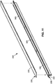
- a plurality of radius filler segments 300 are inserted into the radius cavity 204, and a composite strip 222 (e.g., Figure 11 ) may optionally be assembled over the composite base member 202 to encapsulate the radius filler segments 300 within the radius cavity 204, thereby forming a structural assembly 200 that may be heated and/or cured (e.g., Figure 23 ) to form a cured composite structure 110 (e.g., a composite stringer).
- a composite strip 222 e.g., Figure 11
- one or more structural assemblies 200 may be assembled to a composite skin panel 224 (e.g., cured or uncured) and co-bonded or co-cured to form a cured composite structure 110, such as the wing panel 114 shown in Figure 2 .
- Figure 6 is a magnified view of an example of a composite stringer 116 showing a continuous radius filler element 330 contained within the radius cavity 204 of the composite base member 202.
- Figure 7 is an exploded view of the composite stringer 116.
- the continuous radius filler element 330 is comprised of a plurality of radius filler segments 300 (e.g., Figures 9-10 ) installed in a radius cavity 204 of a composite base member 202 (e.g., Figures 9-10 ) to form a structural assembly 200
- the radius filler elements 330 are arranged in end-to-end relationship with each other to form a segment series 316 ( Figure 10 ) within the radius cavity 204.
- the structural assembly 200 is heated, causing the segment ends 312 (e.g., Figure 9 ) of the radius filler segments 300 to fuse together and form a continuous radius filler element 330.
- the heating of the structural assembly 200 may occur during curing of the composite base member 202 (e.g., Figure 23 ).
- An uncured structural assembly 200 as disclosed herein includes examples where the composite base member 202 and/or a composite panel 220 (e.g., Figure 11 showing composite strip 222, or Figure 28 showing composite skin panel 224) is cured prior to installation of the radius filler segments 300 into the radius cavity 204 for fusing together during the application of heat 412 ( Figure 23 ) to the structural assembly 200.
- the uncured structural assembly 200 may be described as uncured in the sense that as a result of heating, the radius filler segments 300 are fused together to form a continuous radius filler element 330.
- the cured composite structure 110 as disclosed herein may be described as cured in the sense that the radius filler segments 300 are fused together to form a continuous radius filler element 330.
- the composite base member 202 has a generally V-shaped notch described as a radius cavity 204 extending along the length of the composite base member 202.
- the composite base member 202 is comprised of laminated composite plies 112 formed of fiber-reinforced polymer matrix material.
- the composite plies 112 are prepreg composite plies each comprised of reinforcing fibers pre-impregnated with resin (e.g., polymer matrix material).
- the resin of the composite base member 202 may be a thermosetting resin or a thermoplastic resin.
- Thermoplastic resin may comprise any one of a variety of materials including, but not limited to, acrylonitrile butadiene styrene (ABS), acrylic-styrene-acrylonitrile (ASA), polyethylene terephthalate (PET), polyphenylene sulfide (PPS), polylactic acid (PLA), polycarbonate material, polyether ether ketone (PEEK), polyether ketone ketone (PEKK), copolymeric material, acrylics, fluorocarbons, polyamides, polyolefins, polyesters, polycarbonates, polyurethanes, polyetherimides, polyethersulfone, polysulfone, and polyphenylsulfone.
- ABS acrylonitrile butadiene styrene
- ASA acrylic-styrene-acrylonitrile
- PET polyethylene terephthalate
- Thermosetting resin may also be comprised of a variety of materials including, but not limited to, polyurethanes, phenolics, polyimides, sulphonated polymer, a conductive polymer, benzoxazines, bismaleimides, cyanate esters, polyesters, epoxies, and silsesquioxanes.
- the reinforcing fibers of the composite base member 202 may be formed of polymeric material (e.g., plastic), glass, ceramic material, carbon (e.g., graphite), metallic material, or any combination thereof.
- a composite base member 202 may be made from any fiber/resin material combination including, but not limited to, fiberglass/epoxy, carbon/epoxy, carbon/ bismaleimide, and fiberglass/phenolic.
- a composite base member 202 may be formed of two composite channels 208 ( Figures 6-7 ) arranged in back-to-back relation to each other.
- the composite channels 208 ( Figures 6-7 ) each have an L-shaped cross-section which, when assembled, define a T-shaped cross section 126 (e.g., a blade section) of a cured composite structure 110 such as a composite stringer 116.
- a composite base member 202 may have a C-shaped cross-section, a Z-shaped cross-section, or any one of a variety of alternative cross-sectional shapes.
- Composite channels 208 may be assembled to form any one of a variety of different cross-sectional shapes of a cured composite structure 110 such as a J-shaped cross section 128 ( Figure 35 ), an I-shaped cross section 130 ( Figure 36 ), or a hat-shaped cross-section 132 ( Figure 37 ).
- the cured composite structure 110 may be provided in any length.
- any number of radius filler segments 300 may be placed in end-to-end relationship within a radius cavity 204 to form a continuous radius filler element 330 of any length, including lengths of up to 100 feet or more.
- the length of the individual radius filler segments 300 may be based on practicalities associated with manufacturing, handling, and/or installing the radius filler segments 300.
- each composite channel 208 has a web portion 118 and at least one flange portion 122. Each web portion 118 and flange portion 122 are interconnected by a radiused web-flange transition 124.
- the web-flange transitions 124 of the back-to-back composite channels 208 define the above-mentioned lengthwise V-shaped notch which is referred to herein as the radius cavity 204.
- the radius cavity 204 contains the continuous radius filler element 330.
- the radius filler element 330 is a homogenous structure formed of thermoplastic material.
- the radius filler element 330 has a generally triangular cross-sectional shape having opposing concave surfaces 304 configured complementary to the convex surfaces of the opposing web-flange transitions 124 that define the cross-sectional shape of the radius cavity 204.
- a radius filler element 330 e.g., made up of a segment series 316 of end-to-end radius filler segments 300 may extend continuously along an entire length of the composite base member 202.
- thermoplastic material of the radius filler segments 300 that make up the continuous radius filler segments 300 may be provided in any one of a variety of compositions including, but not limited to, acrylonitrile butadiene styrene (ABS), acrylic-styrene-acrylonitrile (ASA), polyethylene terephthalate (PET), polyphenylene sulfide (PPS), polylactic acid (PLA), polycarbonate material, polyether ether ketone (PEEK), polyether ketone ketone (PEKK), and copolymeric material.
- ABS acrylonitrile butadiene styrene
- ASA acrylic-styrene-acrylonitrile
- PET polyethylene terephthalate
- PPS polyphenylene sulfide
- PLA polylactic acid
- PEEK polyether ether ketone
- PEKK polyether ketone ketone
- the thermoplastic material of the radius filler element 330 may optionally contain fibers (not shown) or other filler material distributed throughout the radius filler element 330.
- the fibers may be chopped fibers which may be randomly oriented.
- the fibers may be formed of any one of a variety of materials including polymeric material (e.g., plastic), glass, ceramic material, metallic material, or any combination thereof.
- the radius filler element 330 may be devoid of unidirectional reinforcing fibers extending along a lengthwise direction of the radius filler element 330. However, in other examples described below, the radius filler element 330 may include unidirectional reinforcing fibers.
- the absence of unidirectional reinforcing fibers in the radius filler element 330 may reduce the load-carrying capability of the radius filler element 330, including the load-carrying capability along the lengthwise or axial direction.
- the radius filler element 330 may be described as being non-structural in the sense that the radius filler element 330 may have a relatively low or negligible contribution to the axial strength, axial stiffness, and/or bending stiffness of the cured composite structure 110.
- the radius filler element 330 has a Young's modulus (i.e., modulus of elasticity) that is lower than the Young's modulus of the composite base member 202 (e.g., of the cured composite structure) along the axial or lengthwise direction of the radius filler element 330.
- the radius filler element 330 has a percent elongation at failure (e.g., along the axial or lengthwise direction) that is higher than the present elongation at failure of the composite base member 202 of the cured composite structure 110.
- the transverse direction is perpendicular to the axial or lengthwise direction of the radius filler element 330.
- the presently-disclosed radius filler element 330 may be softer and/or more ductile than the composite base member 202 of the cured composite structure 110, which may render the radius filler element 330 less prone to cracking, as described below.
- a radius filler element 330 having a Young's modulus that is lower than that the Young's modulus of the composite base member 202 allows the cured composite structure 110 to deform significantly in the direction of a load without failure of the radius filler element 330.
- Such failure of the radius filler element 330 may include microcracking which may compromise the structural integrity of the cured composite structure 110 when loaded. Such microcracking may propagate to the side surface interfaces 308 between the radius filler element 330 and the composite base member 202.
- Loading of the cured composite structure 110 may include loads applied to the cured composite structure 110 during service, such as flight loads imposed on a composite wing panel 114 of an aircraft 100 ( Figure 1 ).
- loading of the cured composite structure 110 may also occur due to due to differential shrinkage of the radius filler element 330 relative to the composite base member 202 during curing (e.g., chemical shrinkage) and/or during cool-down (e.g., thermal shrinkage) as the cured composite structure 110 cools down from an elevated cure temperature to room temperature.
- differential shrinkage of the radius filler element 330 relative to the composite base member 202 during curing e.g., chemical shrinkage
- cool-down e.g., thermal shrinkage
- cracking at the side surface interfaces 308 may compromise the load-carrying capability of the cured composite structure 110.
- cracking at the side surface interfaces 308 may compromise the ability of the cured composite structure 110 to withstand a pulloff load 420 exerted by the composite stringers 116 on a composite skin panel 224.
- pulloff loads 420 may be oriented perpendicular to the plane of a composite skin panel 224 and may urge the composite base member 202 away from the composite skin panel 224 with a tendency to separate or de-bond the composite base member 202 from the composite skin panel 224.
- a radius filler element 330 having a Young's modulus that is less than that of the composite base member 202 allows the cured composite structure 110 to strain significantly without the radius filler element 330 carrying some of the load.
- the presently-disclosed radius filler element 330 has a reduced risk of cracking which thereby improves the strength and durability of the cured composite structure 110.
- a radius filler element 330 may be devoid of unidirectional reinforcing fibers
- a radius filler element 330 may include unidirectional reinforcing fibers if such reinforcing fibers result in the radius filler element 330 having a Young's modulus that is relatively closely matched (e.g., within 10%) to the Young's modulus of the composite base member 202.
- the radius filler element 330 may be described as having a percent elongation at failure (e.g., in the axial or lengthwise direction) that is greater than the percent elongation at failure of the composite base member 202.
- Percent elongation at failure may be defined as the percentage increase in length (i.e., from its original length) of a component (not shown) at the breaking point, and is a measure of the ability of the component to stretch prior to breaking.
- a high percent elongation at failure of the radius filler element 330 relative to that of the composite base member 202 represents a reduced axial stiffness of the radius filler element 330 relative to the axial stiffness of the composite base member 202.
- a relatively high percent elongation at failure of the radius filler element 330 means that the stringers may axially strain a significant amount without the risk of failure (e.g., cracking) of the radius filler elements 330.
- the presently-disclosed radius filler element 330 allows for reduced axial stiffness at the terminal ends of the composite stringers 116 which reduces or prevents stress concentrations in the composite skin panel 224 at the terminal ends.
- the radius filler element 330 of a cured composite structure 110 may be fused to one or more portions of the composite base member 202 during curing of the structural assembly 200. More specifically, as described in greater detail below, one or more of the radius filler side surfaces 302 (e.g., the concave surfaces 304) of the radius filler element 330 may be fused to the base member surfaces 206 at the web-flange transitions 124 of the composite base member 202 as a result of the application of heat 412 ( Figure 23 ) during the curing of the structural assembly 200.
- the radius filler side surfaces 302 e.g., the concave surfaces 304
- the flat surface 306 of the radius filler element 330 may be fused to the panel surface 226 of a composite panel 220 such as a composite strip 222 that may assembled to the composite base member 202.
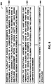
- FIG. 8 shown is a flowchart of operations included in a method 500 of manufacturing a cured composite structure 110.
- the method 500 is described in the context of manufacturing a composite stringer 116 as the cured composite structure 110.
- the method 500 may also be implemented for manufacturing a cured composite structure 110 made up of a composite skin panel 224 and a plurality of composite stringers 116 that may be bonded, co-bonded or co-cured with the composite skin panel 224.
- step 502 of the method includes inserting a plurality of radius filler segments 300 into the radius cavity 204 extending along a length of a composite base member 202 to form a structural assembly 200.
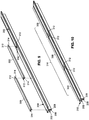
- Figure 9 shows three (3) radius filler segments 300 being installed in the radius cavity 204, any number of radius filler segments 300 may be installed in end-to-end relation within a radius cavity 204.
- the length of individual radius filler segments 300 may be based on practicalities associated with manufacturing and handling the radius filler segments 300.
- the radius filler segments 300 may be provided in a length of 3 feet to allow for manual handling and installation of the individual radius filler segments 300 into the radius cavity 204.
- one or more of the radius filler segments 300 may be provided in a length of 5-10 feet although longer lengths (e.g., approximately 15 feet) are contemplated.
- the length of the individual radius filler segments 300 may be dependent in part upon the total length of the composite base member 202 which, in some examples, may be 30 feet or more such as a 100-foot-length mentioned of a composite stringers 116 of a wing panel 114.
- each radius filler segment 300 has opposing segment ends 312 each having an end surface 314.
- the radius filler segments 300 are formed of the above-described thermoplastic material. As noted above, the thermoplastic material of the radius filler segments 300 has a Young's modulus that is less than the Young's modulus of the composite base member 202 of the cured composite structure 110. Additionally or alternatively, the thermoplastic material of the radius filler segments 300 has a percent elongation at failure that is greater than the percent elongation at failure of the composite base member 202 of the cured composite structure 110.
- the cross-sectional shape and size of the radius filler segments 300 may be complementary to (e.g., matches) the cross-sectional shape and size of the radius cavity 204.
- the back-to-back composite channels 208 that define the composite base member 202 in Figures 9-10 may be supported on a tool (not shown) during the installation of the radius filler segments 300.
- the radius filler segments 300 may be inserted one at a time in the radius cavity 204.
- the segment ends 312 of adjacent pairs of the radius filler segments 300 are preferably placed in abutting contact with each other to facilitate fusing of the segment ends 312 during curing of the composite base member 202.
- relatively small gaps may exist between the segments of one or more end-to-end pairs of radius filler segments 300. Gaps that exist between one or more adjacent pairs of radius filler segments 300 may be at least partially filled by the thermoplastic material if heated to a temperature that reduces the viscosity of the thermoplastic material to an extent allowing the thermoplastic material to fill such gaps during curing of the composite base member 202. In any one of the examples disclosed herein, it is not necessary for the thermoplastic material of the radius filler segments 300 to be heated to its melting temperature in order for the segment ends 312 to fuse together. The temperature at which the segment ends 312 fuse together may be the glass transition temperature of the thermoplastic material, and which may be lower than the melting temperature.
- the method may optionally include assembling a composite panel 220 such as a composite strip 222 over the composite base member 202 to encapsulate the radius filler segments 300 within the radius cavity 204.
- the combination of the composite base member 202, the radius filler segments 300, and the composite strip 222 may define the structural assembly 200 for curing into a cured composite structure 110 as described below.
- the composite panel 220 may be a composite skin panel 224 ( Figure 28 ) having a larger width than the composite strip 222 such that a plurality of composite base members 202 (containing radius filler segments 300) may be assembled to the composite skin panel 224 to form a structural assembly 200 for heating and/or curing to form a cured composite structure 110.
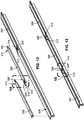
- step 502 of inserting the radius filler segments 300 into the radius cavity 204 may include interlocking the segment ends 312 of end-to-end pairs of the plurality of radius filler segments 300 via interlocking features 320 included on the segment ends 312 of the radius filler segments 300.
- the installation of a radius filler segment 300 into the radius cavity 204 may include engaging the interlocking feature 320 on the segment end 312 of one radius filler segment 300 to the interlocking feature 320 on the segment end 312 of another radius filler segment 300 previously installed in the radius cavity 204.
- the interlocking of the segment ends 312 may ensure that the end surfaces 314 of each opposing pair of segment ends 312 are in contact with each other to improve the fusing together of the end surfaces 314.
- the interlocking features 320 may prevent lengthwise shifting of the position of the radius filler segments 300 within the radius cavity 204.
- the interlocking features 320 may be provided in any one of a variety of different configurations.
- the interlocking of the radius filler segments 300 via the interlocking features 320 may include engaging a tab 322 on the segment end 312 of one radius filler segment 300 with a pocket or recess 324 on the segment end 312 of an adjacent radius filler segment 300.
- the interlocking features 320 may be integrally formed on the segment ends 312 during manufacturing of the radius filler segments 300 using any one a variety of manufacturing methods, as described below.
- the tab 322 has a dovetail configuration 326 configured to nest within a recess 324 also having a dovetail configuration 326 and sized to provide a snug fit of the tab 322 within the recess 324.
- the interlocking features 320 may be provided in any one a variety of different sizes, shapes, and configurations, and are not limited to a tab 322 and a recess 324 having a dovetail configuration 326.
- the method may include manufacturing the radius filler segments 300 via machining, three-dimensional printing, die extrusion, injection molding, and/or using any one of a variety of other manufacturing techniques.
- Three-dimensional printing may include additive manufacturing of radius filler segments 300 such as by stereolithography, selective laser sintering, fused filament fabrication, or any one of a variety of other additive manufacturing techniques.
- three-dimensional printing and/or injection molding allows for manufacturing each radius filler segment 300 to closely match the shape and size defined in an engineering model (e.g., computer-aided-design model) of the radius cavity 204.
- a build surface 356 which may be a mesh plate or a solid sheet or block of material (not shown).
- all of the radius filler segments 300 for a composite base member 202 may be printed on the build surface 356.
- the radius filler segments 300 for a relatively long composite stringer 116 e.g., 60 feet
- relatively small build surface 356 e.g., 2 feet by 3 feet
- all of the radius filler segments 300 for one shipset of a cured composite structure 110 may advantageously be printed on several build surfaces 356, depending upon the size of the of the cured composite structure 110 and the quantity of composite base members 202. At least some of the radius filler segments 300 may be printed on a build surface 356 in spaced parallel relation to each other, and may be spaced apart from each other by up to several inches or more. Alternatively, at least some of the radius filler segments 300 may be nested tightly together or spaced relatively closely together.
- the radius filler segments 300 may include identifying information 354 such as a unique serial number that may be added to each radius filler segment 300 during or after the manufacturing of the radius filler segment 300.
- Each serial number may identify the relative location of each radius filler segment 300 within a segment series 316 ( Figures 9-10 ) of radius filler segments 300 in the radius cavity 204 of a corresponding composite base member 202.
- the serial numbers may identify the composite base member 202 into which each radius filler segments 300 is to be installed.
- the identifying information 354 may be added by ink-stamping, machining, embossing, engraving, stamping, and/or by three dimensionally printing as sunken or raised indicia, or by the use of contrasting color media.
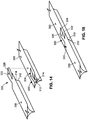
- the manufacturing of the plurality of radius filler segments 300 may optionally include manufacturing the plurality of radius filler segments 300 with breakaway tabs 350 interconnecting the radius filler segments 300.
- the breakaway tabs 350 may be located at spaced intervals along the length of adjacent pairs of radius filler segment 300. In the example of Figure 16 , the breakaway tabs 350 may extend between the side edges 310 of adjacent radius filler segments 300.
- the breakaway tabs 350 provide a means for keeping the radius filler segments 300 together as a shipset prior to separation from each other at the breakaway tabs 350 for individual insertion into the radius cavity 204.
- the breakaway tabs 350 may be additively manufacturing such as via three-dimensional printing during the printing of the radius filler segments 300.
- the interlocking features 320 e.g., Figures 12-15
- each breakaway tab 350 may have one or more weakened portions 352 to facilitate separation of the radius filler segments 300 from each other.
- each breakaway tab 350 may have a notch or groove extending across a width of the breakaway tab 350 proximate the side edge 310 of the radius filler segment 300 at the intersection of the breakaway tab 350 with the radius filler segment 300.
- the cross-section of the weakened portion 352 may be thin enough to be broken away by manually bending back-and-forth until the weakened portion 352 fractures, yet the cross-section of the weakened portion 352 may be thick enough to allow a shipset of the radius filler segments 300 to be lifted off the build surface 356 as a unit and carried and/or handled without causing the individual radius filler segments 300 to separate from each other.
- the radius cavity 204 of a composite base member 202 may have a cross-sectional shape and/or a cross-sectional size that is different at two or more locations along the lengthwise direction of the composite base member 202.
- the cross-sectional size of the radius cavity 204 may taper along the lengthwise direction.
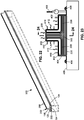
- Figures 18 and 20 show a composite stringer 116 ( Figure 3 ) having a T-shaped cross section 126 in which the local web angle 120 of the web portion 118 varies along the lengthwise direction of the composite stringer 116.
- Figures 19 and 21 show the variation in the cross-sectional shape of the radius filler segment 300 corresponding to the different local web angle 120 in Figures 18 and 20 .
- step 502 of manufacturing radius filler segments 300 may include manufacturing the radius filler segments 300 with a cross-sectional shape and cross-sectional size that is complementary to the cross-sectional shape and cross-sectional size of the radius cavity 204 at the locations of installation of the radius filler segments 300 into the radius cavity 204.
- the radius filler segments 300 may be manufactured with a cross-sectional shape that matches the local web angle 120 of the web portion 118 of the composite base member 202.
- the radius filler segments 300 may be sized and shaped such that the total volume of the radius filler segments 300 is substantially equivalent to, or at least as large as, the volume of the radius cavity 204 after curing of the composite base member 202.
- the radius filler segments 300 are manufactured in a cross-sectional size and/or shape that accounts for resin shrinkage in the composite base member 202.
- radius filler segments 300 for which the cross-sectional shape and/or size of the radius cavity 204 varies along the lengthwise direction of the composite base member 202.
- Manufacturing radius filler segments 300 by die extrusion may result in a constant cross-sectional shape and/or a constant cross-sectional size and which may be appropriate for examples where the radius cavity 204 also has a substantially constant cross-sectional shape and/or substantially constant cross-sectional size.
- thermoplastic material may have enough flexibility to allow radius filler segments 300 of constant cross-sectional shape and/or size to be used in a composite base member 202 having a relatively small variations in the cross-sectional shape and/or cross-sectional size of the radius cavity 204.
- the thermoplastic material of the radius filler segments 300 is relatively insensitive to out-time and temperature, unlike thermosetting materials which must stored at a relatively cold temperature (e.g., in a freezer or refrigerator at 0°F) to prevent premature curing of the thermosetting material prior to layup.
- the manufacturing of the radius filler segments 300 may be performed off-site and in advance of the need for assembly with a composite base member 202 at a production facility.
- the out-time of a composite material e.g., a thermosetting prepreg
- the ability to manufacture the radius filler segments 300 in relatively short lengths may be conducive to manufacturing the radius filler segments 300 off-site, thereby saving valuable floor space and eliminating capital costs associated with on-site equipment for manufacturing radius filler segments 300.
- the structural assembly 200 comprises an uncured composite base member 202 having a base member cure temperature and a radius cavity 204 extending along a length of the composite base member 202.
- the uncured composite base member 202 may include two composite channels 208 configured to be placed in back-to-back relation to each other.
- each composite channel 208 has a web portion 118 ( Figure 6 ) and at least one flange portion 122 ( Figure 6 ) interconnected by a web-flange transition 124 ( Figure 6 ).
- the web portions 118 may be assembled in back-to-back relation to each other and the web-flange transitions 124 collectively form the radius cavity 204 ( Figure 9 ), as mentioned above.
- the structural assembly 200 also includes a plurality of radius filler segments 300 ( Figure 9 ) configured to be inserted into the radius cavity 204 in end-to-end arrangement ( Figures 9-10 ).
- the radius filler segments 300 may have a length of between 3-10 feet which may facilitate manufacturing, storing, shipping, and/or installing the radius filler segments 300.
- the radius filler segments 300 may have a length of less than 3 feet.
- the radius filler segments 300 have a length of between 5-15 feet.
- the radius filler segments 300 may be longer than 15 feet.
- each of the plurality of radius filler segments 300 has opposing segment ends 312 ( Figures 9-10 ).
- the segment ends 312 of the radius filler segments 300 have interlocking features 320 configured to engage with each other and interlock the end-to-end pairs of radius filler segments 300 (e.g., Figures 12-13 ).
- the interlocking features 320 comprise a tab 322 incorporated into the segment end 312 of one of the radius filler segments 300, and a recess 324 incorporated into the segment end 312 of an adjacent one of the radius filler segments 300.
- the tab 322 is configured to nest within the recess 324 for interlocking the radius filler segments 300.
- the interlocking features 320 may be provided in any one of a variety of different configurations, and are not limited to the tab 322 and recess 324 arrangement shown in Figures 12-15 .
- the radius filler segments 300 Prior to insertion into the radius cavity 204 of a composite base member 202, the radius filler segments 300 may be removably interconnected by breakaway tabs 350 as shown in Figures 16-17 .
- the breakaway tabs 350 may interconnect the radius filler segments 300 and thereby allow the radius filler segments 300 to be kept together as a set, and separated just prior to installation into a radius cavity 204 of the composite base member 202.
- the breakaway tabs 350 may each include at least one weakened portion 352 for separating the radius filler segments 300 from each other prior to installation in the radius cavity 204.
- the radius cavity 204 of a structural assembly 200 may have a cross-sectional shape and/or a cross-sectional size that is different at two or more locations along the lengthwise direction of the uncured composite base member 202.
- the cross-sectional shape and/or the cross-sectional size may gradually change along the lengthwise direction of the composite base member 202.
- the cross-sectional shape and cross-sectional size of the radius filler segments 300 may be complementary to the cross-sectional shape and cross-sectional size of the radius cavity 204.
- the radius filler segments 300 may be manufactured with a cross-sectional shape that matches the local web angle 120 which may gradually change along the length of the composite base member 202.
- Each of the radius filler segments 300 is homogenous and is formed of the above-described thermoplastic material.
- the thermoplastic material of the radius filler segments 300 has at least one of the following properties: (1) a Young's modulus that is less than the Young's modulus of the composite base member 202 of the cured composite structure 110, and/or (2) a percent elongation at failure that is greater than the percent elongation at failure of the composite base member 202 of the cured composite structure 110.
- the thermoplastic material has a glass transition temperature at which the segment ends 312 of end-to-end pairs of the plurality of radius filler segments 300 fuse together.
- the base member cure temperature is at least as high as the glass transition temperature of the thermoplastic material.
- the segment ends 312 of the radius filler segments 300 fuse together as described in greater detail below. The fusing together of the radius segment ends 312 result in end-to-end joining of the radius filler segments 300 to form the above-described continuous radius filler element 330 of a cured composite structure 110.
- step 504 of the method 500 (e.g., Figure 8 ) of manufacturing a cured composite structure 110 includes heating the structural assembly 200 to at least a base member cure temperature that causes the segment ends 312 ( Figures 9-10 ) of end-to-end pairs ( Figure 24 ) of the plurality of radius filler segments 300 to fuse together ( Figure 25 ) at the end-to-end interface 318 and form a continuous radius filler element 330 ( Figure 25 ).
- the structural assembly 200 includes the composite base member 202 and the radius filler segments 300 which may be encapsulated between a composite panel 220 and the back-to-back composite channels 208.
- Figures 23 shows the structural assembly 200 as a composite base member 202 (e.g., cured or uncured) having back-to-back composite channels 208 and a composite strip 222 encapsulating the radius filler segments 300
- the structural assembly 200 may be a composite skin panel 224 (e.g., cured or uncured) to which a plurality of composite base members 202 and corresponding radius filler segments 300 (and optional composite strip 222).
- the structural assembly 200 may be mounted on a cure tool 400, and one or more caul plates 402 may optionally be positioned on the composite base member 202.
- Figure 23 shows a pair of L-shaped caul plates 402 respectively positioned on the composite channels 208 of the composite base member 202.
- a vacuum bag 404 and one or more processing layers may be placed over the assembly to facilitate curing.
- the perimeter of the vacuum bag 404 may be sealed to the cure tool 400 using an edge seal 406 such as tape sealant or tacky tape.
- Vacuum fittings (not shown) may be mounted to the vacuum bag 404 and may be fluidly coupled to a vacuum source 408 such as a vacuum pump (not shown).
- the structural assembly 200 may be heated before and/or during the drawing of a vacuum (e.g., via the vacuum source 408) on the space enclosed by the vacuum bag 404 and containing the structural assembly 200.
- the application of vacuum pressure may generate compaction pressure 410 on the structural assembly 200 for consolidating the composite material and radius filler segments 300 while drawing moisture, trapped air, and/or volatiles out of the structural assembly 200.
- the assembly e.g., the structural assembly 200 vacuum bagged to the cure tool 400
- the assembly may be positioned in an autoclave for heating and consolidating the structural assembly 200 during the curing process.
- the structural assembly 200 may be cured in an out-of-autoclave process.
- the structural assembly 200 may be cured in an oven.
- heat 412 may be applied by any one a variety of different mechanisms including, but not limited to, forced air heating, convection heating, induction heating, or other types of heating.
- a structural assembly 200 may be heated from ambient temperature (e.g., room temperature 68°F) to at least the base member cure temperature of the composite base member 202, and may be maintained for a predetermined temperature hold period to allow the composite base member 202 to cure in allow the segment ends 312 ( Figures 9-10 ) of the radius filler segments 300 to fuse together.
- the application of heat 412 may involve removing the prepreg material from cold storage to a room temperature environment and allow the temperature of the prepreg material to increase to room temperature for laying up and curing the composite base member 202.
- Heat 412 may be applied as required to allow the fusing together of the segment ends 312 of the radius filler segments 300 and to promote the curing of the prepreg material.
- the base member cure temperature may be at least as high as the glass transition temperature of the thermoplastic material of the radius filler segments 300.
- the glass transition temperature may be described as the temperature at which the thermoplastic material transitions from a relatively hard, brittle or solid state to a softer, rubbery, or viscous state.
- thermoplastic material at or above its glass transition temperature may allow the thermoplastic material at the end surfaces 314 ( Figure 24 ) to intermingle and fuse together at the end-to-end interface 318 of the radius filler segments 300 as shown in Figure 25 , to form a continuous radius filler element 330 that extends along the length (e.g., the entire length) of the composite base member 202.
- the cure temperature may be at least as high as the melting temperature of the thermoplastic material of the radius filler segments 300.
- the cure temperature may be at least as high as the temperature at which the thermoplastic material of the radius filler segments 300 may flow into any gaps (not shown) or surface voids that may exist on or between the radius filler segments 300 and the composite base member 202.
- the structural assembly 200 may be maintained at the elevated temperature (e.g., at least the base member cure temperature) at least for a temperature hold period (e.g., during one or more curing stages) that allows the end surfaces 314 of adjacent radius filler segments 300 to intermingle and fuse to each other.
- step 504 of heating the structural assembly 200 at least to the base member cure temperature may also include heating the structural assembly 200 to a temperature that results in the radius filler segments 300 at least partially adhering or fusing to the composite base member 202.
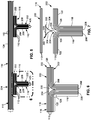
- Figure 26 shows a cross-section of the cured composite structure 110 illustrating the continuous radius filler element 330 encapsulated by the composite strip 222 and the composite channels 208.
- Figure 27 illustrates the side surface interface 308 between each concave surface 304 of the continuous radius filler element 330 and the outer surface of the web-flange transition 124 of each composite channel 208.
- the continuous radius filler element 330 may be fused to the composite base member 202 along any one of the above-described side surface interfaces 308 which may significantly improve the strength and durability of the cured composite structure 110.
- the base member cure temperature may be in the range 150°F to 350°F.
- one type of thermosetting material may have a base member cure temperature of approximately 150°F
- another type of thermosetting material may have a base member cure temperature of approximately 250°F.
- another type of thermosetting material may have a cure temperature of approximately 350°F and which may be compatible with radius filler segments 300 formed of acrylonitrile butadiene styrene (ABS) which may allow the segment ends 312 to fuse together at approximately 350°F.
- ABS acrylonitrile butadiene styrene
- the application of heat 412 may involve moving the composite prepreg material out of cold storage (e.g., from a refrigerator at 40°F) and allowing the composite prepreg material to heat up at least to room temperature for laying up the composite prepreg material into the composite base members 202 prior to installing the radius filler segments 300 and curing the structural assembly 200.
- the thermoplastic material may be selected such that the standard curing process (e.g., specified cure temperatures and hold times) for the material system of the composite base member 202 may be unchanged.
- additional heat may be applied to a structural assembly 200 as needed for fusing together the segment ends 312 of the thermoplastic radius fillers.
- additional heat may be applied to the structural assembly 200 to cause the radius filler segments 300 to fuse together.
- Step 506 of the method 500 includes allowing the structural assembly 200 to cure and cool (e.g., to room temperature) to form the cured composite structure 110 containing a continuous radius filler element 330 as a result of the fusing together of the radius filler segments 300.
- the structural assembly 200 may be cured inside an autoclave or the structural assembly 200 may be cured in an out-of-autoclave process.
- a structural assembly 200 containing radius filler segments 300 may be cured using a multi-stage curing process.
- step 504 of heating the structural assembly 200 may include heating the structural assembly 200 from ambient temperature to a first temperature (e.g., an intermediate temperature) and holding at the first temperature for a first hold period during the first stage of a two-stage curing process.
- the first stage may allow for outgassing of the composite base member 202.
- the first temperature may be lower than the temperature at which the thermosetting resin of the composite base member 202 starts to cross-link and polymerize (e.g., cure).
- the method may further include heating the structural assembly 200 from the first temperature to a second temperature which may be the base member cure temperature, and holding at the second temperature for a second hold period during a second stage of the two-stage curing process.
- the second stage may allow the structural assembly 200 to cure to form the cured composite structure 110 which may be actively cooled and/or passively cooled to result in the cured composite structure 110.
- Either the first temperature or the second temperature is as high as the glass transition temperature of the thermoplastic material of the radius filler segments 300 to allow the segment ends 312 of the radius filler segments 300 to fuse together and form the continuous radius filler element 330.
- the structural assembly 200 may be heated to a first temperature of from 260-290°F for a first hold period of 170-190 minutes.
- the structural assembly 200 may be heated from the first temperature to a second temperature of from 340-370°F for a second hold period of 80-100 minutes.
- the first temperature may be in the range of 270-280°F for a first hold period of 175-185 minutes.
- the second temperature may be in the range of 350-360°F for a second hold period of 85-95 minutes.
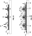
- FIG. 28-31 shown is an example of the process of forming a panel subassembly 230 by mounting a plurality of radius filler segments 300 in end-to-end relation to each other on a composite panel 220 (e.g., cured or uncured) such as a composite skin panel 224 to form a plurality of segment series 316 arranged in spaced parallel relation to each other.
- a composite panel 220 e.g., cured or uncured
- Figures 28-31 illustrate an alternative method for performing step 502 of inserting the radius filler segments 300 into the radius cavity 204.
- the method includes applying location markings 328 of the side edges 310 of each of radius filler segments 300 on an composite panel 220.
- the application of the location markings 328 on the composite panel 220 may be performed by applying relatively light-colored markings for visibility against the relatively dark-colored composite material of the composite panel 220.
- the location markings 328 may be applied on a cured composite panel 220 using a silver pencil.
- the method may also include placing radius filler segments 300 in end-to-an arrangement on the composite panel 220 in alignment with the location markings 328 previously applied to the composite panel 220.
- the location markings 328 may identify the segment ends 312 of each radius filler and may also identify the lateral location of each radius filler element 330 on the composite panel 220.
- End-to-end series of radius filler segments 300 comprises a segment series 316. As shown in Figure 29 , a plurality of segment series 316 may be formed in spaced apart relation to each other on the composite panel 220.
- the combination of the composite panel 220 and the radius filler segments 300 comprises a panel subassembly 230.
- the method may additionally include vacuum compacting the radius filler segments 300 to the composite panel 220 to at least partially bond or lightly adhere the radius filler segments 300 in position on the composite panel 220.
- the process may include placing the panel subassembly 230 on a cure tool 400 and covering the panel subassembly 230 with a vacuum bag 404.
- the perimeter of the vacuum bag 404 may be sealed to the cure tool 400 using an edge seal 406 such as the above-mentioned tape sealant.
- the vacuum bag 404 may be mounted to the vacuum bag 404 for fluidly coupling the vacuum bag 404 to a vacuum source 408 (not shown).
- the drawing of a vacuum on the vacuum bag 404 may compact the radius filler segments 300 against the composite panel 220 which may lightly adhere the radius filler segments 300 to the composite panel 220 and thereby prevent shifting of the positions of the radius filler segments 300 relative to each other during the process of assembling the composite base members 202 and/or during curing of the composite base members 202.
- the relatively rigid nature of the thermoplastic material of the radius filler segments 300 prevents deformation of the cross-sectional shape of the radius filler segments 300 under the compaction pressure applied by the vacuum bag 404 and which may otherwise occur with conventional radius fillers formed of laminated composite prepreg tape.
- the method may further include assembling a plurality of composite base members 202 (e.g., cured or uncured) to the panel subassembly 230 such that the radius filler segments 300 are received into the corresponding radius cavity 204 of the composite base members 202.
- the combination of the composite panel 220, the radius filler segments 300, and the composite base members 202 defines a structural assembly 200.
- the method may additionally include vacuum bagging the structural assembly 200 to the composite panel 220. Similar to the above-described vacuum bagging process shown in Figure 30 , the structural assembly 200 of Figure 31 may be supported on the cure tool 400 and may be covered with a vacuum bag 404 sealed to the cure tool 400. Vacuum pressure may be drawn on the vacuum bag 404 via one or more vacuum fittings (not shown).
- the method may additionally include applying heat 412 to the structural assembly 200 to elevate the temperature to at least a base member cure temperature that causes the segment ends 312 of end-to-end pairs (e.g., Figure 24 ) of the plurality of radius filler segments 300 to fuse together at the end-to-end interface 318 and form a continuous radius filler element 330 ( Figure 25 ) within each one of the composite base members 202, thereby forming a cured composite structure 110.
- a base member cure temperature that causes the segment ends 312 of end-to-end pairs (e.g., Figure 24 ) of the plurality of radius filler segments 300 to fuse together at the end-to-end interface 318 and form a continuous radius filler element 330 ( Figure 25 ) within each one of the composite base members 202, thereby forming a cured composite structure 110.
- the composite base members 202 may be co-bonded or co-cured to the composite skin panel 224, and which result in the fusing together of multiple radius filler segments 300 within each composite base member to form a continuous radius filler element 330 in each composite base member 202.
- Figure 35-37 are non-limiting examples of cross-sectional configurations of cured composite structures 110 using different variations of cross-sections of composite channels 208 for the composite base member 202.
- Figure 35 shows an example of a cured composite structure 110 having a J-shaped cross section 128 formed by assembling a Z-shaped composite channel with an L-shaped composite channel.
- Figure 36 shows an example of a cured composite structure 110 having an I-shaped cross section 130 formed by assembling a pair of C-shaped composite channels in back-to-back relation with each other.
- Figure 37 shows an example of a cured composite structure 110 having a hat-shaped cross section 132 formed by assembling a primary laminate 134, wrap laminate 136, and a composite strip 222 collectively encapsulating a pair of continuous radius filler elements 330 each comprised of a plurality of end-to-end radius filler segments 300.
- radius filler segments 300 formed of thermoplastic material and fused together in end-to-end relationship in a cured composite structure 110 provides significant advantages with regard to manufacturing, structural performance, and cost.
- a cured composite structure 110 having a continuous radius filler element 330 formed of thermoplastic material may be lighter in weight than a comparable cured composite structure in which the radius filler is formed of laminated carbon-epoxy composite plies.
- a plurality of radius filler segments 300 can be manufactured in relatively short lengths which may be more conducive to handling, storing, shipping, and assembling than a conventional radius filler formed of composite plies and extending the entire length of a cured composite structure.
- thermoplastic material of the radius filler segments 300 may not require cold storage which is typically required for thermosetting prepreg composite plies as used for manufacturing conventional radius fillers.
- the presently-disclosed radius filler segments 300 may be manufactured off-site in advance and stored until needed, and which may eliminate capital equipment costs associated with on-site manufacturing equipment for manufacturing conventional radius fillers formed of composite plies.
- the radius filler segments 300 may be manufactured by three-dimensional (3D) printing which advantageously allows for closely matching the shape requirements based on an engineering model (e.g., CAD model) of the radius cavity 204.
- 3D printing the relatively short length of the radius filler segments 300 is conducive to off-site manufacturing by a vendor.
- the ability to 3D print the radius filler segments 300 is conducive to on-site manufacturing.
- the cost of an on-site 3D printing machine is relatively low compared to the cost of specialized laminating machines required for laying up composite plies of a conventional radius filler.
- 3D printing machines may be used for on-site manufacturing of a variety of components, and are not limited to radius filler segments 300.
- Another advantage of 3D printing is that the thermoplastic material from which the radius filler segments 300 are fabricated may be selected to be compatible with a variety of prepreg material systems from which the composite base member 202 may be formed.
Landscapes
- Engineering & Computer Science (AREA)
- Mechanical Engineering (AREA)
- Chemical & Material Sciences (AREA)
- Composite Materials (AREA)
- Textile Engineering (AREA)
- Architecture (AREA)
- Civil Engineering (AREA)
- Structural Engineering (AREA)
- Manufacturing & Machinery (AREA)
- Materials Engineering (AREA)
- Moulding By Coating Moulds (AREA)
Abstract
Description
- The present disclosure relates generally to composites manufacturing and, more particularly, to a composite structure having a thermoplastic radius filler and a method of manufacturing the composite structure.
- Composite structures are used in a wide variety of applications due to their high strength-to-weight ratio, corrosion resistance, and other favorable properties. In aircraft construction, composites are used in increasing quantities to form the fuselage, wings, and other components. For example, the wings of an aircraft may include composite skin panels reinforced by composite stringers.
- Composite stringers may be provided in a variety of cross-sectional shapes. For example, a composite stringer of a wing panel may have a T-shaped cross-section formed by assembling a pair of composite channels (e.g., L-shaped channels) in back-to-back arrangement. Each composite channel includes a flange portion and a web portion joined at a radiused web-flange transition. The web portions of the composite channels are assembled in back-to-back arrangement to form a composite base member, and which results in a lengthwise notch in the composite base member defined by the web-flange transitions of the back-to-back composite channels. The lengthwise notch may be referred to as a radius cavity of the composite stringer. To improve the strength, stiffness, and durability of a composite structure having composite stringers, it is necessary to fill each radius cavity with a radius filler.
- Conventional methods of manufacturing and installing radius fillers present several challenges. For example, one method involves laying up individual strips of prepreg composite material (e.g., unidirectional reinforcing fibers pre-impregnated with resin) into the radius cavity of a composite base member. Each strip of prepreg composite material may be cut to a precise width prior to installation as an individual composite ply into the radius cavity. The ply-by-ply installation of individual strips of prepreg composite material is labor-intensive and time-consuming.
- Another method of manufacturing radius fillers involves pre-fabricating each radius filler to match the shape of the radius cavity to be filled. Individual strips of prepreg composite material are laid up in stacked formation to form a radius filler on a layup tool prior to installation of the radius filler in the radius cavity. For a radius filler having unidirectional reinforcing fibers, the axial stiffness of the radius filler and the composite base member may be mismatched. For example, the lengthwise orientation of the unidirectional reinforcing fibers in the radius filler results in a high axial stiffness of the radius filler relative to the axial stiffness of the composite base member. The mismatch in axial stiffness between the radius filler and the composite base member may result in undesirable strength characteristics in the cured composite structure. The effects of relatively high axial stiffness of a radius filler may be pronounced at the terminal ends of a composite stringer where reduced axial stiffness is desired.
- One approach for reducing the mismatch in axial stiffness of a radius filler relative to a composite base member is to manufacture the radius filler using a laminating machine configured to laminate prepreg composite plies having non-zero degree fiber orientations (e.g., +/- 30 degrees) in addition to laminating composite plies having a zero-degree fiber orientation. The ability to lay up individual composite plies with non-zero fiber orientations provides a means for more closely matching the axial stiffness of the radius filler with the axial stiffness of the composite base member. In addition, the composite plies may be laid up such that the axial stiffness of the radius filler is reduced at the terminal ends of the composite stringer. While the above-described manufacturing method is structurally advantageous, laminating machines represent a significant capital expense for construction, operation, and maintenance.
- As can be seen, there exists a need in the art for a system and method of manufacturing a composite structure having a radius filler that avoids the above-noted challenges.
- The above-noted needs associated with radius fillers are specifically addressed and alleviated by the present disclosure which provides a method of manufacturing a cured composite structure. The method includes inserting a plurality of radius filler segments into a radius cavity extending along a length of an uncured composite base member to form an uncured structural assembly. The plurality of radius filler segments are placed in end-to-end arrangement within the radius cavity and each radius filler segment has opposing segment ends and is formed of a thermoplastic material. The method also includes heating the structural assembly at least to a base member cure temperature that causes the segment ends of end-to-end pairs of the radius filler segments to fuse together and form a continuous radius filler element that extends along the length of the composite base member. The method additionally includes allowing the structural assembly to cure to form a cured composite structure.
- Also disclosed is an uncured structural assembly having a composite base member and a plurality of radius filler segments. The composite base member has a base member cure temperature and a radius cavity extending along a length of the composite base member. The plurality of radius filler segments are configured to be inserted into the radius cavity in end-to-end arrangement. The plurality of radius filler segments each have opposing segment ends and are homogenous and are formed of a thermoplastic material. The thermoplastic material has a temperature at which the segment ends of end-to-end pairs of the plurality of radius filler segments fuse together. The base member cure temperature is at least as high as the temperature at which the segment ends of the radius filler segments fuse together.
- Also disclosed is a cured composite structure having a composite base member and a radius filler element. The composite base member has a radius cavity extending along a length of the composite base member. The radius filler element is contained in the radius cavity and extends continuously along a length of the radius cavity. The radius filler element is homogenous and is formed of a thermoplastic material having at least one of the following two properties: (1) the radius filler element has a Young's modulus that is less than the Young's modulus of the composite base member, and/or (2) the radius filler element has a percent elongation at failure that is greater than the percent elongation at failure of the composite base member.
- The features, functions and advantages that have been discussed can be achieved independently in various embodiments of the present disclosure or may be combined in yet other embodiments, further details of which can be seen with reference to the following description and drawings below.
- These and other features of the present disclosure will become more apparent upon reference to the drawings wherein like numbers refer to like parts throughout and wherein:
-
Figure 1 is a perspective view of an aircraft; -
Figure 2 is a top-down view of an example of a cured composite structure configured as a wing panel of an aircraft, the wing panel having a composite skin panel and a plurality of composite stringers; -
Figure 3 is a sectional view of the wing panel taken along line 3-3 ofFigure 2 and illustrating a composite stringer coupled to the composite skin panel; -
Figure 4 is a sectional view of the wing panel taken along line 4-4ofFigure 2 and illustrating a plurality of composite stringers coupled to the composite skin panel; -
Figure 5 is a magnified view of the portion of the wing panel identified byreference numeral 5 inFigure 4 and illustrating a continuous radius filler element formed of thermoplastic material and filling the radius cavity of each composite stringer; -
Figure 6 is a magnified view of one of the composite stringers showing the continuous radius filler element contained within the radius cavity which is defined by the composite base member and a composite strip; -
Figure 7 is an exploded view of the composite stringer ofFigure 6 ; -
Figure 8 is a flowchart of operations included in a method of manufacturing a cured composite structure; -
Figure 9 is a partially exploded perspective view of an example of an uncured composite base member and a plurality of radius filler segments formed of thermoplastic material and configured to be inserted into the radius cavity of the uncured composite base member to form a structural assembly in which the radius filler segments are in end-to end arrangement within the radius cavity; -
Figure 10 is a perspective view of the structural assembly ofFigure 9 showing the radius filler segments in end-to end arrangement to form a segment series within the radius cavity of the uncured composite base member; -
Figure 11 is a partially exploded perspective view of the structural assembly and illustrating an uncured composite strip positionable over the uncured composite base member for capturing the radius filler segments within the radius cavity; -
Figure 12 is a partially exploded perspective view of a further example of a plurality of radius filler segments each having interlocking features for interlocking the segments ends of the radius filler segments within the radius cavity of the uncured composite base member; -
Figure 13 is a perspective view of the structural assembly ofFigure 12 showing the interlocking features coupling the radius filler segments in end-to-end arrangement; -
Figure 14 is an exploded view of an example of two radius filler segments having interlocking features configured in a dovetail configuration for interlocking the segment ends of the radius filler segments; -
Figure 15 is an assembled view of the radius filler segments ofFigure 14 ; -
Figure 16 is a perspective view of an example of a plurality of radius filler segments three-dimensionally printed on a build plate and interconnected by a plurality of breakaway tabs formed via the three-dimensional printing of the radius filler segments; -
Figure 17 is a magnified view of the portion of the radius filler segment identified byreference numeral 17 ofFigure 16 and illustrating a weakened portion located along a side edge of the radius filler segment for separating the breakaway from the radius filler segment; -
Figure 18 is a sectional view of an example of a composite stringer taken along line 18-18 ofFigure 3 and illustrating the composite channels each having a web portion oriented perpendicular to a flange portion of the composite base member; -
Figure 19 is a magnified view of the continuous radius filler element inFigure 18 ; -
Figure 20 is a sectional view of an example of a composite stringer taken along line 26-26 ofFigure 3 and illustrating the web portions oriented at a web angle that is non-perpendicular to the flange portions of the composite base member; -
Figure 21 is a magnified view of the continuous radius filler element inFigure 20 ; -
Figure 22 is a perspective view of an example of the structural assembly ofFigure 13 rotated 180 degree such that the composite panel is on a bottom side of the structural assembly; -
Figure 23 is a sectional view of an example of the structural assembly ofFigure 22 vacuum bagged to a cure tool and illustrating the application of heat and pressure for curing the structural assembly; -
Figure 24 is a sectional view of the structural assembly taken along line 24-24 ofFigure 23 during the application of heat and pressure, and illustrating the segment ends of a pair of radius filler segments in abutting contact with each other to define an end-to-end interface between the end surfaces of the segment ends; -
Figure 25 is a sectional view of a cured composite structure after curing of the structural assembly ofFigure 24 and illustrating the segment ends of the radius filler segments fused together at the end-to-end interface as a result of heating the structural assembly; -
Figure 26 is a sectional view of the cured composite structure taken along line 26-26 ofFigure 25 and illustrating a continuous radius filler element formed by the fusing together of the end-to-end radius filler segments during the application of heat; -
Figure 27 is a magnified view of the portion of the cured composite structure identified byreference numeral 27 ofFigure 26 and illustrating the radius filler side surfaces of the radius filler fused to the base member surfaces and/or panel surface respectively of the composite base member and composite strip; -
Figure 28 is a perspective view of an example of an uncured composite skin panel having a plurality of location markings identifying the location of each radius filler segment on the composite skin panel for assembling an panel subassembly; -
Figure 29 is a perspective view of the panel subassembly during placement of the radius filler segments in alignment with the location markings; -
Figure 30 is a sectional view of the panel subassembly ofFigure 28 vacuum bagged to a cure tool and illustrating the application of pressure for at least partially adhering the radius filler segments to the surface of the composite skin panel; -
Figure 31 is a sectional view of the panel subassembly ofFigure 30 after removal of the vacuum bag and illustrating a plurality of composite base members assembled to the panel subassembly such that the radius filler segments are received into the radius filler cavities of the plurality of composite base members to form a structural assembly; -
Figure 32 is a sectional view of the structural assembly ofFigure 31 vacuum bagged to the cure tool and illustrating the application of heat and pressure for curing the structural assembly; -
Figure 33 is a sectional view of a cured composite article resulting from the curing of the structural assembly ofFigure 32 ; -
Figure 34 is a perspective view of the cured composite article ofFigure 33 ; -
Figure 35 is a sectional view of an example of a cured composite structure containing a continuous radius filler element and configured in a J-shaped cross-section; -
Figure 36 is a sectional view of an example of a cured composite structure containing a continuous radius filler element and configured in an I-shaped cross-section; and -
Figure 37 is a sectional view of an example of a cured composite structure containing a continuous radius filler element and configured in a hat-shaped cross-section. - Referring now to the drawings which illustrate preferred and various embodiments of the disclosure, shown in
Figure 1 is a perspective view of anaircraft 100 which may include one or more curedcomposite structures 110, one or more of which may have a continuous radius filler element 330 (Figure 6 ) formed of thermoplastic material and manufactured as described below. Theaircraft 100 may include afuselage 102, ahorizontal tail 104, avertical tail 106, and a pair ofwings 108, any one or more of which may represent curedcomposite structures 110. For example,Figure 2 shows a curedcomposite structure 110 configured aswing panel 114 having acomposite skin panel 224 and a plurality ofcomposite stringers 116, each of which may include a continuousradius filler element 330.Figure 3 is a spanwise sectional view of thewing panel 114 showing acomposite stringer 116 coupled to thecomposite skin panel 224.Figure 4 is a chordwise sectional view of thewing panel 114 showing the plurality ofcomposite stringers 116 coupled to thecomposite skin panel 224. -
Figure 5 is a magnified view of a portion of thewing panel 114 showing thecomposite stringers 116 coupled to thecomposite skin panel 224. Thecomposite skin panel 224 is formed ofcomposite plies 112 which may be separately laid up on a wing skin layup tool (not shown). Each one of the stringers comprises acomposite base member 202 which, in the example shown, is made up of back-to-back composite channels 208 each having an L-shaped configuration. Each one of thecomposite channels 208 is formed ofcomposite plies 112 which may be laid up on a base member layup tool (not shown) and assembled in back-to back relationship to form acomposite base member 202. A plurality of radius filler segments 300 (e.g.,Figure 9 ) are inserted into theradius cavity 204, and a composite strip 222 (e.g.,Figure 11 ) may optionally be assembled over thecomposite base member 202 to encapsulate theradius filler segments 300 within theradius cavity 204, thereby forming astructural assembly 200 that may be heated and/or cured (e.g.,Figure 23 ) to form a cured composite structure 110 (e.g., a composite stringer). Alternatively, one or more structural assemblies 200 (e.g., cured or uncured) may be assembled to a composite skin panel 224 (e.g., cured or uncured) and co-bonded or co-cured to form a curedcomposite structure 110, such as thewing panel 114 shown inFigure 2 . -
Figure 6 is a magnified view of an example of acomposite stringer 116 showing a continuousradius filler element 330 contained within theradius cavity 204 of thecomposite base member 202.Figure 7 is an exploded view of thecomposite stringer 116. As described in greater detail below, the continuousradius filler element 330 is comprised of a plurality of radius filler segments 300 (e.g.,Figures 9-10 ) installed in aradius cavity 204 of a composite base member 202 (e.g.,Figures 9-10 ) to form astructural assembly 200 Theradius filler elements 330 are arranged in end-to-end relationship with each other to form a segment series 316 (Figure 10 ) within theradius cavity 204. Thestructural assembly 200 is heated, causing the segment ends 312 (e.g.,Figure 9 ) of theradius filler segments 300 to fuse together and form a continuousradius filler element 330. In some examples, the heating of thestructural assembly 200 may occur during curing of the composite base member 202 (e.g.,Figure 23 ). - An uncured
structural assembly 200 as disclosed herein includes examples where thecomposite base member 202 and/or a composite panel 220 (e.g.,Figure 11 showingcomposite strip 222, orFigure 28 showing composite skin panel 224) is cured prior to installation of theradius filler segments 300 into theradius cavity 204 for fusing together during the application of heat 412 (Figure 23 ) to thestructural assembly 200. In such examples, the uncuredstructural assembly 200 may be described as uncured in the sense that as a result of heating, theradius filler segments 300 are fused together to form a continuousradius filler element 330. In this same regard, the curedcomposite structure 110 as disclosed herein may be described as cured in the sense that theradius filler segments 300 are fused together to form a continuousradius filler element 330. - As shown in
Figures 6-7 , thecomposite base member 202 has a generally V-shaped notch described as aradius cavity 204 extending along the length of thecomposite base member 202. Thecomposite base member 202 is comprised of laminated composite plies 112 formed of fiber-reinforced polymer matrix material. The composite plies 112 are prepreg composite plies each comprised of reinforcing fibers pre-impregnated with resin (e.g., polymer matrix material). - The resin of the
composite base member 202 may be a thermosetting resin or a thermoplastic resin. Thermoplastic resin may comprise any one of a variety of materials including, but not limited to, acrylonitrile butadiene styrene (ABS), acrylic-styrene-acrylonitrile (ASA), polyethylene terephthalate (PET), polyphenylene sulfide (PPS), polylactic acid (PLA), polycarbonate material, polyether ether ketone (PEEK), polyether ketone ketone (PEKK), copolymeric material, acrylics, fluorocarbons, polyamides, polyolefins, polyesters, polycarbonates, polyurethanes, polyetherimides, polyethersulfone, polysulfone, and polyphenylsulfone. Thermosetting resin may also be comprised of a variety of materials including, but not limited to, polyurethanes, phenolics, polyimides, sulphonated polymer, a conductive polymer, benzoxazines, bismaleimides, cyanate esters, polyesters, epoxies, and silsesquioxanes. The reinforcing fibers of thecomposite base member 202 may be formed of polymeric material (e.g., plastic), glass, ceramic material, carbon (e.g., graphite), metallic material, or any combination thereof. In view of the above-mentioned material compositions for the resin and the reinforcing fibers, acomposite base member 202 may be made from any fiber/resin material combination including, but not limited to, fiberglass/epoxy, carbon/epoxy, carbon/ bismaleimide, and fiberglass/phenolic. - As mentioned above, a composite base member 202 (
Figures 6-7 ) may be formed of two composite channels 208 (Figures 6-7 ) arranged in back-to-back relation to each other. In the example ofFigures 5-7 , the composite channels 208 (Figures 6-7 ) each have an L-shaped cross-section which, when assembled, define a T-shaped cross section 126 (e.g., a blade section) of a curedcomposite structure 110 such as acomposite stringer 116. However, in other examples (e.g.,Figure 35-37 ), one or more of thecomposite channels 208 of acomposite base member 202 may have a C-shaped cross-section, a Z-shaped cross-section, or any one of a variety of alternative cross-sectional shapes.Composite channels 208 may be assembled to form any one of a variety of different cross-sectional shapes of a curedcomposite structure 110 such as a J-shaped cross section 128 (Figure 35 ), an I-shaped cross section 130 (Figure 36 ), or a hat-shaped cross-section 132 (Figure 37 ). The curedcomposite structure 110 may be provided in any length. As described below, any number ofradius filler segments 300 may be placed in end-to-end relationship within aradius cavity 204 to form a continuousradius filler element 330 of any length, including lengths of up to 100 feet or more. As described below, the length of the individualradius filler segments 300 may be based on practicalities associated with manufacturing, handling, and/or installing theradius filler segments 300. - Referring still to
Figures 5-7 , regardless of cross-sectional shape, eachcomposite channel 208 has aweb portion 118 and at least oneflange portion 122. Eachweb portion 118 andflange portion 122 are interconnected by a radiused web-flange transition 124. Whencomposite channels 208 are assembled in back-to-back relationship, the web-flange transitions 124 of the back-to-back composite channels 208 define the above-mentioned lengthwise V-shaped notch which is referred to herein as theradius cavity 204. To improve the strength characteristics of a curedcomposite structure 110, theradius cavity 204 contains the continuousradius filler element 330. - The
radius filler element 330 is a homogenous structure formed of thermoplastic material. Theradius filler element 330 has a generally triangular cross-sectional shape having opposingconcave surfaces 304 configured complementary to the convex surfaces of the opposing web-flange transitions 124 that define the cross-sectional shape of theradius cavity 204. In some examples, a radius filler element 330 (e.g., made up of asegment series 316 of end-to-end radius filler segments 300) may extend continuously along an entire length of thecomposite base member 202. The thermoplastic material of theradius filler segments 300 that make up the continuousradius filler segments 300 may be provided in any one of a variety of compositions including, but not limited to, acrylonitrile butadiene styrene (ABS), acrylic-styrene-acrylonitrile (ASA), polyethylene terephthalate (PET), polyphenylene sulfide (PPS), polylactic acid (PLA), polycarbonate material, polyether ether ketone (PEEK), polyether ketone ketone (PEKK), and copolymeric material. - The thermoplastic material of the
radius filler element 330 may optionally contain fibers (not shown) or other filler material distributed throughout theradius filler element 330. The fibers may be chopped fibers which may be randomly oriented. The fibers may be formed of any one of a variety of materials including polymeric material (e.g., plastic), glass, ceramic material, metallic material, or any combination thereof. In some examples, theradius filler element 330 may be devoid of unidirectional reinforcing fibers extending along a lengthwise direction of theradius filler element 330. However, in other examples described below, theradius filler element 330 may include unidirectional reinforcing fibers. - The absence of unidirectional reinforcing fibers in the
radius filler element 330 may reduce the load-carrying capability of theradius filler element 330, including the load-carrying capability along the lengthwise or axial direction. In this regard, theradius filler element 330 may be described as being non-structural in the sense that theradius filler element 330 may have a relatively low or negligible contribution to the axial strength, axial stiffness, and/or bending stiffness of the curedcomposite structure 110. - For the presently-disclosed cured
composite structure 110, theradius filler element 330 has a Young's modulus (i.e., modulus of elasticity) that is lower than the Young's modulus of the composite base member 202 (e.g., of the cured composite structure) along the axial or lengthwise direction of theradius filler element 330. Alternatively or additionally, theradius filler element 330 has a percent elongation at failure (e.g., along the axial or lengthwise direction) that is higher than the present elongation at failure of thecomposite base member 202 of the curedcomposite structure 110. In the present disclosure, the transverse direction is perpendicular to the axial or lengthwise direction of theradius filler element 330. The presently-disclosedradius filler element 330 may be softer and/or more ductile than thecomposite base member 202 of the curedcomposite structure 110, which may render theradius filler element 330 less prone to cracking, as described below. - Advantageously, a
radius filler element 330 having a Young's modulus that is lower than that the Young's modulus of thecomposite base member 202 allows the curedcomposite structure 110 to deform significantly in the direction of a load without failure of theradius filler element 330. Such failure of theradius filler element 330 may include microcracking which may compromise the structural integrity of the curedcomposite structure 110 when loaded. Such microcracking may propagate to the side surface interfaces 308 between theradius filler element 330 and thecomposite base member 202. Loading of the curedcomposite structure 110 may include loads applied to the curedcomposite structure 110 during service, such as flight loads imposed on acomposite wing panel 114 of an aircraft 100 (Figure 1 ). Alternatively or additionally, loading of the curedcomposite structure 110 may also occur due to due to differential shrinkage of theradius filler element 330 relative to thecomposite base member 202 during curing (e.g., chemical shrinkage) and/or during cool-down (e.g., thermal shrinkage) as the curedcomposite structure 110 cools down from an elevated cure temperature to room temperature. - As may be appreciated, cracking at the side surface interfaces 308 may compromise the load-carrying capability of the cured
composite structure 110. For example, cracking at the side surface interfaces 308 may compromise the ability of the curedcomposite structure 110 to withstand apulloff load 420 exerted by thecomposite stringers 116 on acomposite skin panel 224. As shown inFigure 5 , such pulloff loads 420 may be oriented perpendicular to the plane of acomposite skin panel 224 and may urge thecomposite base member 202 away from thecomposite skin panel 224 with a tendency to separate or de-bond thecomposite base member 202 from thecomposite skin panel 224. Advantageously in the present disclosure, aradius filler element 330 having a Young's modulus that is less than that of thecomposite base member 202 allows the curedcomposite structure 110 to strain significantly without theradius filler element 330 carrying some of the load. In this regard, the presently-disclosedradius filler element 330 has a reduced risk of cracking which thereby improves the strength and durability of the curedcomposite structure 110. Although the above description indicates that theradius filler element 330 may be devoid of unidirectional reinforcing fibers, in some examples, aradius filler element 330 may include unidirectional reinforcing fibers if such reinforcing fibers result in theradius filler element 330 having a Young's modulus that is relatively closely matched (e.g., within 10%) to the Young's modulus of thecomposite base member 202. - As an alternative to or in addition to the above-described Young's modulus arrangement, the
radius filler element 330 may be described as having a percent elongation at failure (e.g., in the axial or lengthwise direction) that is greater than the percent elongation at failure of thecomposite base member 202. Percent elongation at failure may be defined as the percentage increase in length (i.e., from its original length) of a component (not shown) at the breaking point, and is a measure of the ability of the component to stretch prior to breaking. In the present disclosure, a high percent elongation at failure of theradius filler element 330 relative to that of thecomposite base member 202 represents a reduced axial stiffness of theradius filler element 330 relative to the axial stiffness of thecomposite base member 202. In the context ofcomposite stringers 116 coupled to acomposite skin panel 224 as shown inFigure 5 , a relatively high percent elongation at failure of theradius filler element 330 means that the stringers may axially strain a significant amount without the risk of failure (e.g., cracking) of theradius filler elements 330. In addition, the presently-disclosedradius filler element 330 allows for reduced axial stiffness at the terminal ends of thecomposite stringers 116 which reduces or prevents stress concentrations in thecomposite skin panel 224 at the terminal ends. - In some examples, the
radius filler element 330 of a curedcomposite structure 110 may be fused to one or more portions of thecomposite base member 202 during curing of thestructural assembly 200. More specifically, as described in greater detail below, one or more of the radius filler side surfaces 302 (e.g., the concave surfaces 304) of theradius filler element 330 may be fused to the base member surfaces 206 at the web-flange transitions 124 of thecomposite base member 202 as a result of the application of heat 412 (Figure 23 ) during the curing of thestructural assembly 200. Alternatively or additionally, as a result of the curing of thestructural assembly 200, theflat surface 306 of theradius filler element 330 may be fused to thepanel surface 226 of acomposite panel 220 such as acomposite strip 222 that may assembled to thecomposite base member 202. - Referring to
Figure 8 , shown is a flowchart of operations included in amethod 500 of manufacturing a curedcomposite structure 110. Themethod 500 is described in the context of manufacturing acomposite stringer 116 as the curedcomposite structure 110. However, themethod 500 may also be implemented for manufacturing a curedcomposite structure 110 made up of acomposite skin panel 224 and a plurality ofcomposite stringers 116 that may be bonded, co-bonded or co-cured with thecomposite skin panel 224. - Referring to
Figures 9-10 , step 502 of the method includes inserting a plurality ofradius filler segments 300 into theradius cavity 204 extending along a length of acomposite base member 202 to form astructural assembly 200. AlthoughFigure 9 shows three (3)radius filler segments 300 being installed in theradius cavity 204, any number ofradius filler segments 300 may be installed in end-to-end relation within aradius cavity 204. As mentioned above, the length of individualradius filler segments 300 may be based on practicalities associated with manufacturing and handling theradius filler segments 300. For example, theradius filler segments 300 may be provided in a length of 3 feet to allow for manual handling and installation of the individualradius filler segments 300 into theradius cavity 204. However, one or more of theradius filler segments 300 may be provided in a length of 5-10 feet although longer lengths (e.g., approximately 15 feet) are contemplated. The length of the individualradius filler segments 300 may be dependent in part upon the total length of thecomposite base member 202 which, in some examples, may be 30 feet or more such as a 100-foot-length mentioned of acomposite stringers 116 of awing panel 114. As described above, eachradius filler segment 300 has opposing segment ends 312 each having anend surface 314. - The
radius filler segments 300 are formed of the above-described thermoplastic material. As noted above, the thermoplastic material of theradius filler segments 300 has a Young's modulus that is less than the Young's modulus of thecomposite base member 202 of the curedcomposite structure 110. Additionally or alternatively, the thermoplastic material of theradius filler segments 300 has a percent elongation at failure that is greater than the percent elongation at failure of thecomposite base member 202 of the curedcomposite structure 110. - The cross-sectional shape and size of the
radius filler segments 300 may be complementary to (e.g., matches) the cross-sectional shape and size of theradius cavity 204. The back-to-back composite channels 208 that define thecomposite base member 202 inFigures 9-10 may be supported on a tool (not shown) during the installation of theradius filler segments 300. In some examples, theradius filler segments 300 may be inserted one at a time in theradius cavity 204. The segment ends 312 of adjacent pairs of theradius filler segments 300 are preferably placed in abutting contact with each other to facilitate fusing of the segment ends 312 during curing of thecomposite base member 202. However, in other examples, relatively small gaps (e.g., less than 0.10 inch wide - not shown) may exist between the segments of one or more end-to-end pairs ofradius filler segments 300. Gaps that exist between one or more adjacent pairs ofradius filler segments 300 may be at least partially filled by the thermoplastic material if heated to a temperature that reduces the viscosity of the thermoplastic material to an extent allowing the thermoplastic material to fill such gaps during curing of thecomposite base member 202. In any one of the examples disclosed herein, it is not necessary for the thermoplastic material of theradius filler segments 300 to be heated to its melting temperature in order for the segment ends 312 to fuse together. The temperature at which the segment ends 312 fuse together may be the glass transition temperature of the thermoplastic material, and which may be lower than the melting temperature. - Referring to
Figure 11 , the method may optionally include assembling acomposite panel 220 such as acomposite strip 222 over thecomposite base member 202 to encapsulate theradius filler segments 300 within theradius cavity 204. The combination of thecomposite base member 202, theradius filler segments 300, and thecomposite strip 222 may define thestructural assembly 200 for curing into a curedcomposite structure 110 as described below. In an alternative example not shown, thecomposite panel 220 may be a composite skin panel 224 (Figure 28 ) having a larger width than thecomposite strip 222 such that a plurality of composite base members 202 (containing radius filler segments 300) may be assembled to thecomposite skin panel 224 to form astructural assembly 200 for heating and/or curing to form a curedcomposite structure 110. - Referring to
Figures 12-13 , step 502 of inserting theradius filler segments 300 into theradius cavity 204 may include interlocking the segment ends 312 of end-to-end pairs of the plurality ofradius filler segments 300 via interlocking features 320 included on the segment ends 312 of theradius filler segments 300. For example, the installation of aradius filler segment 300 into theradius cavity 204 may include engaging theinterlocking feature 320 on thesegment end 312 of oneradius filler segment 300 to theinterlocking feature 320 on thesegment end 312 of anotherradius filler segment 300 previously installed in theradius cavity 204. The interlocking of the segment ends 312 may ensure that the end surfaces 314 of each opposing pair of segment ends 312 are in contact with each other to improve the fusing together of the end surfaces 314. In addition, the interlocking features 320 may prevent lengthwise shifting of the position of theradius filler segments 300 within theradius cavity 204. The interlocking features 320 may be provided in any one of a variety of different configurations. - For example, referring to
Figures 14-15 , the interlocking of theradius filler segments 300 via the interlocking features 320 may include engaging atab 322 on thesegment end 312 of oneradius filler segment 300 with a pocket or recess 324 on thesegment end 312 of an adjacentradius filler segment 300. As described in greater detail below, the interlocking features 320 may be integrally formed on the segment ends 312 during manufacturing of theradius filler segments 300 using any one a variety of manufacturing methods, as described below. In the example shown, thetab 322 has adovetail configuration 326 configured to nest within arecess 324 also having adovetail configuration 326 and sized to provide a snug fit of thetab 322 within therecess 324. However, the interlocking features 320 may be provided in any one a variety of different sizes, shapes, and configurations, and are not limited to atab 322 and arecess 324 having adovetail configuration 326. - The method may include manufacturing the
radius filler segments 300 via machining, three-dimensional printing, die extrusion, injection molding, and/or using any one of a variety of other manufacturing techniques. Three-dimensional printing may include additive manufacturing ofradius filler segments 300 such as by stereolithography, selective laser sintering, fused filament fabrication, or any one of a variety of other additive manufacturing techniques. Advantageously, three-dimensional printing and/or injection molding allows for manufacturing eachradius filler segment 300 to closely match the shape and size defined in an engineering model (e.g., computer-aided-design model) of theradius cavity 204. - Referring to
Figure 16 , shown is an example of a plurality ofradius filler segments 300 three-dimensionally printed on abuild surface 356 which may be a mesh plate or a solid sheet or block of material (not shown). In some examples, all of theradius filler segments 300 for acomposite base member 202 may be printed on thebuild surface 356. Advantageously, theradius filler segments 300 for a relatively long composite stringer 116 (e.g., 60 feet) may be printed on relatively small (e.g., 2 feet by 3 feet)build surface 356. In still further examples, all of theradius filler segments 300 for one shipset of a cured composite structure 110 (e.g., a composite wing panel 114) may advantageously be printed onseveral build surfaces 356, depending upon the size of the of the curedcomposite structure 110 and the quantity ofcomposite base members 202. At least some of theradius filler segments 300 may be printed on abuild surface 356 in spaced parallel relation to each other, and may be spaced apart from each other by up to several inches or more. Alternatively, at least some of theradius filler segments 300 may be nested tightly together or spaced relatively closely together. - In
Figure 16 , theradius filler segments 300 may include identifyinginformation 354 such as a unique serial number that may be added to eachradius filler segment 300 during or after the manufacturing of theradius filler segment 300. Each serial number may identify the relative location of eachradius filler segment 300 within a segment series 316 (Figures 9-10 ) ofradius filler segments 300 in theradius cavity 204 of a correspondingcomposite base member 202. In this regard, the serial numbers may identify thecomposite base member 202 into which eachradius filler segments 300 is to be installed. The identifyinginformation 354 may be added by ink-stamping, machining, embossing, engraving, stamping, and/or by three dimensionally printing as sunken or raised indicia, or by the use of contrasting color media. - The manufacturing of the plurality of
radius filler segments 300 may optionally include manufacturing the plurality ofradius filler segments 300 withbreakaway tabs 350 interconnecting theradius filler segments 300. Thebreakaway tabs 350 may be located at spaced intervals along the length of adjacent pairs ofradius filler segment 300. In the example ofFigure 16 , thebreakaway tabs 350 may extend between the side edges 310 of adjacentradius filler segments 300. Advantageously, thebreakaway tabs 350 provide a means for keeping theradius filler segments 300 together as a shipset prior to separation from each other at thebreakaway tabs 350 for individual insertion into theradius cavity 204. Thebreakaway tabs 350 may be additively manufacturing such as via three-dimensional printing during the printing of theradius filler segments 300. Alternatively or additionally, the interlocking features 320 (e.g.,Figures 12-15 ) may also be additively manufactured via three-dimensional printing during printing of theradius filler segments 300. - Referring to
Figure 17 , eachbreakaway tab 350 may have one or moreweakened portions 352 to facilitate separation of theradius filler segments 300 from each other. In the example shown, eachbreakaway tab 350 may have a notch or groove extending across a width of thebreakaway tab 350 proximate theside edge 310 of theradius filler segment 300 at the intersection of thebreakaway tab 350 with theradius filler segment 300. The cross-section of the weakenedportion 352 may be thin enough to be broken away by manually bending back-and-forth until the weakenedportion 352 fractures, yet the cross-section of the weakenedportion 352 may be thick enough to allow a shipset of theradius filler segments 300 to be lifted off thebuild surface 356 as a unit and carried and/or handled without causing the individualradius filler segments 300 to separate from each other. - Referring to
Figures 18-21 , in some examples, theradius cavity 204 of acomposite base member 202 may have a cross-sectional shape and/or a cross-sectional size that is different at two or more locations along the lengthwise direction of thecomposite base member 202. For example, the cross-sectional size of theradius cavity 204 may taper along the lengthwise direction. In another example,Figures 18 and 20 show a composite stringer 116 (Figure 3 ) having a T-shapedcross section 126 in which thelocal web angle 120 of theweb portion 118 varies along the lengthwise direction of thecomposite stringer 116.Figures 19 and 21 show the variation in the cross-sectional shape of theradius filler segment 300 corresponding to the differentlocal web angle 120 inFigures 18 and 20 . In such example, step 502 of manufacturingradius filler segments 300 may include manufacturing theradius filler segments 300 with a cross-sectional shape and cross-sectional size that is complementary to the cross-sectional shape and cross-sectional size of theradius cavity 204 at the locations of installation of theradius filler segments 300 into theradius cavity 204. In one example, theradius filler segments 300 may be manufactured with a cross-sectional shape that matches thelocal web angle 120 of theweb portion 118 of thecomposite base member 202. In addition, in the above-described manufacturing techniques, theradius filler segments 300 may be sized and shaped such that the total volume of theradius filler segments 300 is substantially equivalent to, or at least as large as, the volume of theradius cavity 204 after curing of thecomposite base member 202. In this regard, theradius filler segments 300 are manufactured in a cross-sectional size and/or shape that accounts for resin shrinkage in thecomposite base member 202. - Advantageously, three-dimensional printing, injection molding, machining, and certain other manufacturing techniques allow for manufacturing
radius filler segments 300 for which the cross-sectional shape and/or size of theradius cavity 204 varies along the lengthwise direction of thecomposite base member 202. Manufacturingradius filler segments 300 by die extrusion may result in a constant cross-sectional shape and/or a constant cross-sectional size and which may be appropriate for examples where theradius cavity 204 also has a substantially constant cross-sectional shape and/or substantially constant cross-sectional size. However, the thermoplastic material may have enough flexibility to allowradius filler segments 300 of constant cross-sectional shape and/or size to be used in acomposite base member 202 having a relatively small variations in the cross-sectional shape and/or cross-sectional size of theradius cavity 204. - Advantageously, the thermoplastic material of the
radius filler segments 300 is relatively insensitive to out-time and temperature, unlike thermosetting materials which must stored at a relatively cold temperature (e.g., in a freezer or refrigerator at 0°F) to prevent premature curing of the thermosetting material prior to layup. In view of the insensitivity of thermoplastic material to out-time and temperature, the manufacturing of theradius filler segments 300 may be performed off-site and in advance of the need for assembly with acomposite base member 202 at a production facility. As known in the art, the out-time of a composite material (e.g., a thermosetting prepreg) may be described as the amount of time that the composite material may be taken out of cold storage and exposed to ambient temperature and which may reduce the shelf life of the composite material. Furthermore, the ability to manufacture theradius filler segments 300 in relatively short lengths may be conducive to manufacturing theradius filler segments 300 off-site, thereby saving valuable floor space and eliminating capital costs associated with on-site equipment for manufacturingradius filler segments 300. - Referring to
Figure 22 , shown is an example of astructural assembly 200 prior to curing. As described above, thestructural assembly 200 comprises an uncuredcomposite base member 202 having a base member cure temperature and aradius cavity 204 extending along a length of thecomposite base member 202. The uncuredcomposite base member 202 may include twocomposite channels 208 configured to be placed in back-to-back relation to each other. As described above, eachcomposite channel 208 has a web portion 118 (Figure 6 ) and at least one flange portion 122 (Figure 6 ) interconnected by a web-flange transition 124 (Figure 6 ). Theweb portions 118 may be assembled in back-to-back relation to each other and the web-flange transitions 124 collectively form the radius cavity 204 (Figure 9 ), as mentioned above. - The
structural assembly 200 also includes a plurality of radius filler segments 300 (Figure 9 ) configured to be inserted into theradius cavity 204 in end-to-end arrangement (Figures 9-10 ). In some examples, theradius filler segments 300 may have a length of between 3-10 feet which may facilitate manufacturing, storing, shipping, and/or installing theradius filler segments 300. However, theradius filler segments 300 may have a length of less than 3 feet. In still other examples, theradius filler segments 300 have a length of between 5-15 feet. However, theradius filler segments 300 may be longer than 15 feet. - As also described above, each of the plurality of
radius filler segments 300 has opposing segment ends 312 (Figures 9-10 ). As shown inFigures 12-15 , in some examples, the segment ends 312 of theradius filler segments 300 have interlocking features 320 configured to engage with each other and interlock the end-to-end pairs of radius filler segments 300 (e.g.,Figures 12-13 ). In the example ofFigures 14-15 , the interlocking features 320 comprise atab 322 incorporated into thesegment end 312 of one of theradius filler segments 300, and arecess 324 incorporated into thesegment end 312 of an adjacent one of theradius filler segments 300. Thetab 322 is configured to nest within therecess 324 for interlocking theradius filler segments 300. However, as mentioned above, the interlocking features 320 may be provided in any one of a variety of different configurations, and are not limited to thetab 322 andrecess 324 arrangement shown inFigures 12-15 . - Prior to insertion into the
radius cavity 204 of acomposite base member 202, theradius filler segments 300 may be removably interconnected bybreakaway tabs 350 as shown inFigures 16-17 . As described above, thebreakaway tabs 350 may interconnect theradius filler segments 300 and thereby allow theradius filler segments 300 to be kept together as a set, and separated just prior to installation into aradius cavity 204 of thecomposite base member 202. Thebreakaway tabs 350 may each include at least one weakenedportion 352 for separating theradius filler segments 300 from each other prior to installation in theradius cavity 204. - As shown in
Figures 18-21 , theradius cavity 204 of astructural assembly 200 may have a cross-sectional shape and/or a cross-sectional size that is different at two or more locations along the lengthwise direction of the uncuredcomposite base member 202. For example, the cross-sectional shape and/or the cross-sectional size may gradually change along the lengthwise direction of thecomposite base member 202. The cross-sectional shape and cross-sectional size of theradius filler segments 300 may be complementary to the cross-sectional shape and cross-sectional size of theradius cavity 204. For example, as shown inFigures 18-21 , theradius filler segments 300 may be manufactured with a cross-sectional shape that matches thelocal web angle 120 which may gradually change along the length of thecomposite base member 202. - Each of the
radius filler segments 300 is homogenous and is formed of the above-described thermoplastic material. As described above, the thermoplastic material of theradius filler segments 300 has at least one of the following properties: (1) a Young's modulus that is less than the Young's modulus of thecomposite base member 202 of the curedcomposite structure 110, and/or (2) a percent elongation at failure that is greater than the percent elongation at failure of thecomposite base member 202 of the curedcomposite structure 110. - As described in greater detail below, in a
structural assembly 200, the thermoplastic material has a glass transition temperature at which the segment ends 312 of end-to-end pairs of the plurality ofradius filler segments 300 fuse together. The base member cure temperature is at least as high as the glass transition temperature of the thermoplastic material. During heating of thestructural assembly 200, the segment ends 312 of theradius filler segments 300 fuse together as described in greater detail below. The fusing together of the radius segment ends 312 result in end-to-end joining of theradius filler segments 300 to form the above-described continuousradius filler element 330 of a curedcomposite structure 110. - Referring to
Figure 23 ,step 504 of the method 500 (e.g.,Figure 8 ) of manufacturing a curedcomposite structure 110 includes heating thestructural assembly 200 to at least a base member cure temperature that causes the segment ends 312 (Figures 9-10 ) of end-to-end pairs (Figure 24 ) of the plurality ofradius filler segments 300 to fuse together (Figure 25 ) at the end-to-end interface 318 and form a continuous radius filler element 330 (Figure 25 ). As shown inFigure 23 , thestructural assembly 200 includes thecomposite base member 202 and theradius filler segments 300 which may be encapsulated between acomposite panel 220 and the back-to-back composite channels 208. AlthoughFigures 23 shows thestructural assembly 200 as a composite base member 202 (e.g., cured or uncured) having back-to-back composite channels 208 and acomposite strip 222 encapsulating theradius filler segments 300, in another example not shown, thestructural assembly 200 may be a composite skin panel 224 (e.g., cured or uncured) to which a plurality ofcomposite base members 202 and corresponding radius filler segments 300 (and optional composite strip 222). Regardless of the configuration, thestructural assembly 200 may be mounted on acure tool 400, and one ormore caul plates 402 may optionally be positioned on thecomposite base member 202. For example,Figure 23 shows a pair of L-shapedcaul plates 402 respectively positioned on thecomposite channels 208 of thecomposite base member 202. Avacuum bag 404 and one or more processing layers (e.g., a breather layer, a release layer - not shown) may be placed over the assembly to facilitate curing. The perimeter of thevacuum bag 404 may be sealed to thecure tool 400 using anedge seal 406 such as tape sealant or tacky tape. Vacuum fittings (not shown) may be mounted to thevacuum bag 404 and may be fluidly coupled to avacuum source 408 such as a vacuum pump (not shown). - The
structural assembly 200 may be heated before and/or during the drawing of a vacuum (e.g., via the vacuum source 408) on the space enclosed by thevacuum bag 404 and containing thestructural assembly 200. The application of vacuum pressure may generatecompaction pressure 410 on thestructural assembly 200 for consolidating the composite material andradius filler segments 300 while drawing moisture, trapped air, and/or volatiles out of thestructural assembly 200. In some examples, the assembly (e.g., thestructural assembly 200 vacuum bagged to the cure tool 400) may be positioned in an autoclave for heating and consolidating thestructural assembly 200 during the curing process. In other examples, thestructural assembly 200 may be cured in an out-of-autoclave process. In some examples, thestructural assembly 200 may be cured in an oven. - To cure a
structural assembly 200,heat 412 may be applied by any one a variety of different mechanisms including, but not limited to, forced air heating, convection heating, induction heating, or other types of heating. In some examples, astructural assembly 200 may be heated from ambient temperature (e.g., room temperature 68°F) to at least the base member cure temperature of thecomposite base member 202, and may be maintained for a predetermined temperature hold period to allow thecomposite base member 202 to cure in allow the segment ends 312 (Figures 9-10 ) of theradius filler segments 300 to fuse together. In other examples involving acomposite base member 202 formed of prepreg material that cures at or slightly above room temperature, the application ofheat 412 may involve removing the prepreg material from cold storage to a room temperature environment and allow the temperature of the prepreg material to increase to room temperature for laying up and curing thecomposite base member 202.Heat 412 may be applied as required to allow the fusing together of the segment ends 312 of theradius filler segments 300 and to promote the curing of the prepreg material. - Referring to
Figures 24-25 , in order to promote the fusing of the segment ends 312 of adjacent pairs ofradius filler segments 300 at each end-to-end interface 318 (Figure 24 ), the base member cure temperature may be at least as high as the glass transition temperature of the thermoplastic material of theradius filler segments 300. The glass transition temperature may be described as the temperature at which the thermoplastic material transitions from a relatively hard, brittle or solid state to a softer, rubbery, or viscous state. The viscous nature of the thermoplastic material at or above its glass transition temperature may allow the thermoplastic material at the end surfaces 314 (Figure 24 ) to intermingle and fuse together at the end-to-end interface 318 of theradius filler segments 300 as shown inFigure 25 , to form a continuousradius filler element 330 that extends along the length (e.g., the entire length) of thecomposite base member 202. In other examples, the cure temperature may be at least as high as the melting temperature of the thermoplastic material of theradius filler segments 300. Alternatively or additionally, in some examples, the cure temperature may be at least as high as the temperature at which the thermoplastic material of theradius filler segments 300 may flow into any gaps (not shown) or surface voids that may exist on or between theradius filler segments 300 and thecomposite base member 202. Thestructural assembly 200 may be maintained at the elevated temperature (e.g., at least the base member cure temperature) at least for a temperature hold period (e.g., during one or more curing stages) that allows the end surfaces 314 of adjacentradius filler segments 300 to intermingle and fuse to each other. - Referring to
Figures 26-27 , in some examples, step 504 of heating thestructural assembly 200 at least to the base member cure temperature may also include heating thestructural assembly 200 to a temperature that results in theradius filler segments 300 at least partially adhering or fusing to thecomposite base member 202. For example,Figure 26 shows a cross-section of the curedcomposite structure 110 illustrating the continuousradius filler element 330 encapsulated by thecomposite strip 222 and thecomposite channels 208.Figure 27 illustrates theside surface interface 308 between eachconcave surface 304 of the continuousradius filler element 330 and the outer surface of the web-flange transition 124 of eachcomposite channel 208. Also shown is theside surface interface 308 between theflat surface 306 of the continuousradius filler element 330 and thepanel surface 226 of thecomposite strip 222 on the bottom of the curedcomposite structure 110. The continuousradius filler element 330 may be fused to thecomposite base member 202 along any one of the above-described side surface interfaces 308 which may significantly improve the strength and durability of the curedcomposite structure 110. - For a
composite base member 202 formed of a thermosetting material, the base member cure temperature may be in the range 150°F to 350°F. For example, one type of thermosetting material may have a base member cure temperature of approximately 150°F, and another type of thermosetting material may have a base member cure temperature of approximately 250°F. Still further, another type of thermosetting material may have a cure temperature of approximately 350°F and which may be compatible withradius filler segments 300 formed of acrylonitrile butadiene styrene (ABS) which may allow the segment ends 312 to fuse together at approximately 350°F. - For
composite base members 202 formed of composite prepreg material that cures at room temperature (e.g., 68-72°F) or slightly above (e.g., 80-85°F), the application ofheat 412 may involve moving the composite prepreg material out of cold storage (e.g., from a refrigerator at 40°F) and allowing the composite prepreg material to heat up at least to room temperature for laying up the composite prepreg material into thecomposite base members 202 prior to installing theradius filler segments 300 and curing thestructural assembly 200. Advantageously, the thermoplastic material may be selected such that the standard curing process (e.g., specified cure temperatures and hold times) for the material system of thecomposite base member 202 may be unchanged. However, in some examples, additional heat may be applied to astructural assembly 200 as needed for fusing together the segment ends 312 of the thermoplastic radius fillers. For configurations in which thecomposite base members 202 are made of a composite prepreg material that cures at temperatures slightly above room temperature (e.g., 80-85°F), additional heat may be applied to thestructural assembly 200 to cause theradius filler segments 300 to fuse together. - Step 506 of the
method 500 includes allowing thestructural assembly 200 to cure and cool (e.g., to room temperature) to form the curedcomposite structure 110 containing a continuousradius filler element 330 as a result of the fusing together of theradius filler segments 300. As mentioned above, thestructural assembly 200 may be cured inside an autoclave or thestructural assembly 200 may be cured in an out-of-autoclave process. In some examples, astructural assembly 200 containingradius filler segments 300 may be cured using a multi-stage curing process. For example, step 504 of heating thestructural assembly 200 may include heating thestructural assembly 200 from ambient temperature to a first temperature (e.g., an intermediate temperature) and holding at the first temperature for a first hold period during the first stage of a two-stage curing process. The first stage may allow for outgassing of thecomposite base member 202. The first temperature may be lower than the temperature at which the thermosetting resin of thecomposite base member 202 starts to cross-link and polymerize (e.g., cure). The method may further include heating thestructural assembly 200 from the first temperature to a second temperature which may be the base member cure temperature, and holding at the second temperature for a second hold period during a second stage of the two-stage curing process. The second stage may allow thestructural assembly 200 to cure to form the curedcomposite structure 110 which may be actively cooled and/or passively cooled to result in the curedcomposite structure 110. Either the first temperature or the second temperature is as high as the glass transition temperature of the thermoplastic material of theradius filler segments 300 to allow the segment ends 312 of theradius filler segments 300 to fuse together and form the continuousradius filler element 330. - In a specific example of a two-stage curing process in which the
composite base member 202 is formed of graphite-epoxy prepreg, during the first stage thestructural assembly 200 may be heated to a first temperature of from 260-290°F for a first hold period of 170-190 minutes. During the second stage, thestructural assembly 200 may be heated from the first temperature to a second temperature of from 340-370°F for a second hold period of 80-100 minutes. In a preferred example, during the first stage, the first temperature may be in the range of 270-280°F for a first hold period of 175-185 minutes. During the second stage, the second temperature may be in the range of 350-360°F for a second hold period of 85-95 minutes. - Referring to
Figures 28-31 , shown is an example of the process of forming apanel subassembly 230 by mounting a plurality ofradius filler segments 300 in end-to-end relation to each other on a composite panel 220 (e.g., cured or uncured) such as acomposite skin panel 224 to form a plurality ofsegment series 316 arranged in spaced parallel relation to each other. In this regard,Figures 28-31 illustrate an alternative method for performing step 502 of inserting theradius filler segments 300 into theradius cavity 204. Referring toFigure 28 , the method includes applyinglocation markings 328 of the side edges 310 of each ofradius filler segments 300 on ancomposite panel 220. The application of thelocation markings 328 on thecomposite panel 220 may be performed by applying relatively light-colored markings for visibility against the relatively dark-colored composite material of thecomposite panel 220. For example, thelocation markings 328 may be applied on a curedcomposite panel 220 using a silver pencil. - Referring to
Figure 29 , the method may also include placingradius filler segments 300 in end-to-an arrangement on thecomposite panel 220 in alignment with thelocation markings 328 previously applied to thecomposite panel 220. Thelocation markings 328 may identify the segment ends 312 of each radius filler and may also identify the lateral location of eachradius filler element 330 on thecomposite panel 220. End-to-end series ofradius filler segments 300 comprises asegment series 316. As shown inFigure 29 , a plurality ofsegment series 316 may be formed in spaced apart relation to each other on thecomposite panel 220. The combination of thecomposite panel 220 and theradius filler segments 300 comprises apanel subassembly 230. - Referring to
Figure 30 , the method may additionally include vacuum compacting theradius filler segments 300 to thecomposite panel 220 to at least partially bond or lightly adhere theradius filler segments 300 in position on thecomposite panel 220. The process may include placing thepanel subassembly 230 on acure tool 400 and covering thepanel subassembly 230 with avacuum bag 404. The perimeter of thevacuum bag 404 may be sealed to thecure tool 400 using anedge seal 406 such as the above-mentioned tape sealant. One or more vacuum fittings - (not shown) may be mounted to the
vacuum bag 404 for fluidly coupling thevacuum bag 404 to a vacuum source 408 (not shown). The drawing of a vacuum on thevacuum bag 404 may compact theradius filler segments 300 against thecomposite panel 220 which may lightly adhere theradius filler segments 300 to thecomposite panel 220 and thereby prevent shifting of the positions of theradius filler segments 300 relative to each other during the process of assembling thecomposite base members 202 and/or during curing of thecomposite base members 202. Advantageously, the relatively rigid nature of the thermoplastic material of theradius filler segments 300 prevents deformation of the cross-sectional shape of theradius filler segments 300 under the compaction pressure applied by thevacuum bag 404 and which may otherwise occur with conventional radius fillers formed of laminated composite prepreg tape. - Referring to
Figure 31 , the method may further include assembling a plurality of composite base members 202 (e.g., cured or uncured) to thepanel subassembly 230 such that theradius filler segments 300 are received into thecorresponding radius cavity 204 of thecomposite base members 202. The combination of thecomposite panel 220, theradius filler segments 300, and thecomposite base members 202 defines astructural assembly 200. - Referring to
Figure 32 , the method may additionally include vacuum bagging thestructural assembly 200 to thecomposite panel 220. Similar to the above-described vacuum bagging process shown inFigure 30 , thestructural assembly 200 ofFigure 31 may be supported on thecure tool 400 and may be covered with avacuum bag 404 sealed to thecure tool 400. Vacuum pressure may be drawn on thevacuum bag 404 via one or more vacuum fittings (not shown). As described above with regard toFigure 23 , the method may additionally include applyingheat 412 to thestructural assembly 200 to elevate the temperature to at least a base member cure temperature that causes the segment ends 312 of end-to-end pairs (e.g.,Figure 24 ) of the plurality ofradius filler segments 300 to fuse together at the end-to-end interface 318 and form a continuous radius filler element 330 (Figure 25 ) within each one of thecomposite base members 202, thereby forming a curedcomposite structure 110. - Referring to
Figures 33-34 , shown is an example of the curedcomposite structure 110 resulting from the curing of thestructural assembly 200 ofFigure 32 . Thecomposite base members 202 may be co-bonded or co-cured to thecomposite skin panel 224, and which result in the fusing together of multipleradius filler segments 300 within each composite base member to form a continuousradius filler element 330 in eachcomposite base member 202. - As mentioned above, shown in
Figure 35-37 are non-limiting examples of cross-sectional configurations of curedcomposite structures 110 using different variations of cross-sections ofcomposite channels 208 for thecomposite base member 202. For example,Figure 35 shows an example of a curedcomposite structure 110 having a J-shapedcross section 128 formed by assembling a Z-shaped composite channel with an L-shaped composite channel.Figure 36 shows an example of a curedcomposite structure 110 having an I-shapedcross section 130 formed by assembling a pair of C-shaped composite channels in back-to-back relation with each other.Figure 37 shows an example of a curedcomposite structure 110 having a hat-shapedcross section 132 formed by assembling aprimary laminate 134, wraplaminate 136, and acomposite strip 222 collectively encapsulating a pair of continuousradius filler elements 330 each comprised of a plurality of end-to-endradius filler segments 300. - Advantageously, the use of
radius filler segments 300 formed of thermoplastic material and fused together in end-to-end relationship in a curedcomposite structure 110 provides significant advantages with regard to manufacturing, structural performance, and cost. For example, a curedcomposite structure 110 having a continuousradius filler element 330 formed of thermoplastic material may be lighter in weight than a comparable cured composite structure in which the radius filler is formed of laminated carbon-epoxy composite plies. In addition, a plurality ofradius filler segments 300 can be manufactured in relatively short lengths which may be more conducive to handling, storing, shipping, and assembling than a conventional radius filler formed of composite plies and extending the entire length of a cured composite structure. Furthermore, the thermoplastic material of theradius filler segments 300 may not require cold storage which is typically required for thermosetting prepreg composite plies as used for manufacturing conventional radius fillers. In this regard, the presently-disclosedradius filler segments 300 may be manufactured off-site in advance and stored until needed, and which may eliminate capital equipment costs associated with on-site manufacturing equipment for manufacturing conventional radius fillers formed of composite plies. - As mentioned above, the
radius filler segments 300 may be manufactured by three-dimensional (3D) printing which advantageously allows for closely matching the shape requirements based on an engineering model (e.g., CAD model) of theradius cavity 204. As mentioned above, the relatively short length of theradius filler segments 300 is conducive to off-site manufacturing by a vendor. However, the ability to 3D print theradius filler segments 300 is conducive to on-site manufacturing. Advantageously, the cost of an on-site 3D printing machine is relatively low compared to the cost of specialized laminating machines required for laying up composite plies of a conventional radius filler. Furthermore, 3D printing machines may be used for on-site manufacturing of a variety of components, and are not limited toradius filler segments 300. Another advantage of 3D printing is that the thermoplastic material from which theradius filler segments 300 are fabricated may be selected to be compatible with a variety of prepreg material systems from which thecomposite base member 202 may be formed. - Further, the disclosure comprises examples according to the following clauses:
- Clause 1. An uncured structural assembly, comprising:
- a composite base member having a base member cure temperature and a radius cavity extending along a length of the composite base member;
- a plurality of radius filler segments configured to be inserted into the radius cavity in end-to-end arrangement, the plurality of radius filler segments each having opposing segment ends and being homogenous and formed of a thermoplastic material;
- the thermoplastic material having a temperature at which the segment ends of end-to-end pairs of the plurality of radius filler segments fuse together; and
- the base member cure temperature being at least as high as the temperature at which the segment ends of the radius filler segments fuse together.
- Clause 2. The uncured structural assembly of Clause 1, wherein:
the segment ends each have interlocking features configured to interlock end-to-end pairs of the plurality of radius filler segments. - Clause 3. The uncured structural assembly of Clause 1 or 2 wherein:
the plurality of radius filler segments are removably interconnected by breakaway tabs prior to separation from each other for insertion into the radius cavity. - Clause 4. A cured composite structure, comprising:
- a composite base member having a radius cavity extending along a length of the composite base member;
- a radius filler element in the radius cavity and extending continuously along a length of the radius cavity, the radius filler element being homogenous and formed of a thermoplastic material having at least one of the following two properties:
- the radius filler element having a Young's modulus that is less than the Young's modulus of the composite base member; and
- the radius filler element having a percent elongation at failure that is greater than the percent elongation at failure of the composite base member.
-
Clause 5. The uncured structural assembly of any of Clauses 1 to 4, wherein the thermoplastic material of the radius filler segments is comprised of at least one of:
acrylonitrile butadiene styrene (ABS), acrylic-styrene-acrylonitrile (ASA), polyethylene terephthalate (PET), polyphenylene sulfide (PPS), polylactic acid (PLA), polycarbonate material, polyether ether ketone (PEEK), polyether ketone ketone (PEKK), copolymeric material. -
Clause 6. The uncured structural assembly of any of Clauses 1 to 5, wherein:- the base member is comprised of reinforcing fibers embedded in resin;
- the resin of the composite base member comprises one of thermosetting resin and thermoplastic resin;
- the thermoplastic resin comprises one of the following: acrylonitrile butadiene styrene (ABS), acrylic-styrene-acrylonitrile (ASA), polyethylene terephthalate (PET), polyphenylene sulfide (PPS), polylactic acid (PLA), polycarbonate material, polyether ether ketone (PEEK), polyether ketone ketone (PEKK), copolymeric material; acrylics, fluorocarbons, polyamides, polyolefins, polyesters, polycarbonates, polyurethanes, polyetherimides, polyethersulfone, polysulfone, and polyphenylsulfone; and
- the thermosetting resin comprises one of the following: polyurethanes, phenolics, polyimides, sulphonated polymer, a conductive polymer, benzoxazines, bismaleimides, cyanate esthers, polyesters, epoxies, and silsesquioxanes; and
- the reinforcing fibers of the composite base member are formed of at least one of plastic, glass, ceramic, carbon, metal or any combination thereof.
- Additional modifications and improvements of the present disclosure may be apparent to those of ordinary skill in the art. Thus, the particular combination of parts described and illustrated herein is intended to represent only certain embodiments of the present disclosure and is not intended to serve as limitations of alternative embodiments or devices within the spirit and scope of the disclosure.
Claims (15)
- A method of manufacturing a cured composite structure (110), comprising:inserting a plurality of radius filler segments (300) into a radius cavity (204) extending along a length of an uncured composite base member (202) to form an uncured structural assembly (200), the plurality of radius filler segments (300) being in end-to-end arrangement within the radius cavity (204) and each having opposing segment ends (312) and being formed of a thermoplastic material;heating the structural assembly (200) at least to a base member cure temperature that causes the segment ends (312) of end-to-end pairs of the plurality of radius filler segments (300) to fuse together and form a continuous radius filler element (330) that extends along the length of the composite base member (202); andallowing the structural assembly (200) to cure to form a cured composite structure (110).
- The method of Claim 1, wherein the step of heating the structural assembly (200) at least to the base member cure temperature includes:
heating the structural assembly (200) to a temperature at least as high as the base member cure temperature and which causes the radius filler segments (300) to adhere to the composite base member (202). - The method of any of the preceding claims, wherein:the radius filler segments (300) each have a length of 3-15 feet; andthe composite base member (202) has a length of greater than 15 feet.
- The method of any of the preceding claims, wherein the step of inserting the plurality of radius filler segments (300) into the radius cavity (204) includes:
interlocking the segment ends (312) of end-to-end pairs of the plurality of radius filler segments (300) via interlocking features (320) included on the segment ends (312) of the radius filler segments (300). - The method of any of the preceding claims, further comprising:
manufacturing at least one of the radius filler segments (300) by one of three-dimensional printing, selective laser sintering, fused filament fabrication, die extrusion, or injection molding. - The method of Claim 5, wherein manufacturing at least one of the radius filler segments (300) includes:
manufacturing the plurality of radius filler segments (300) with breakaway tabs (350) interconnecting the radius filler segments (300). - The method of any of the preceding claims, wherein inserting the plurality of radius filler segments (300) into the radius cavity (204) comprises:applying location markings (328) on an composite panel (220) indicating locations of the radius filler segments (300);placing the radius filler segments (300) on the composite panel (220) in alignment with the location markings (328) to form at least one segment series (316) of end-to-end radius filler segments (300);vacuum compacting the radius filler segments (300) to the composite panel (220) to at least partially bond the radius filler segments (300) in position on the composite panel (220) to form a panel subassembly (230); andassembling at least one composite base member (202) to the panel subassembly (230) such that the radius filler segments (300) of the segment series (316) are received into the radius cavity (204) of the composite base member (202) to form the structural assembly (200).
- The method of any of the preceding claims, wherein the thermoplastic material of the radius filler segments (300) is comprised of at least one of:
acrylonitrile butadiene styrene (ABS), acrylic-styrene-acrylonitrile (ASA), polyethylene terephthalate (PET), polyphenylene sulfide (PPS), polylactic acid (PLA), polycarbonate material, polyether ether ketone (PEEK), polyether ketone ketone (PEKK), copolymeric material. - The method of any of the preceding claims, wherein:
the thermoplastic material of the radius filler segments (300) has a Young's modulus that is less than the Young's modulus of the composite base member (202). - The method of any of the preceding claims, wherein:
the thermoplastic material of the radius filler segments (300) has a percent elongation at failure that is greater than the percent elongation at failure of the composite base member (202). - The method of any of the preceding claims, wherein:the composite base member (202) is comprised of reinforcing fibers embedded in a resin;the resin of the composite base member (202) comprises one of thermosetting resin and thermoplastic resin;the thermoplastic resin comprises one of the following: acrylonitrile butadiene styrene (ABS), acrylic-styrene-acrylonitrile (ASA), polyethylene terephthalate (PET), polyphenylene sulfide (PPS), polylactic acid (PLA), polycarbonate material, polyether ether ketone (PEEK), polyether ketone ketone (PEKK), copolymeric material; acrylics, fluorocarbons, polyamides, polyolefins, polyesters, polycarbonates, polyurethanes, polyetherimides, polyethersulfone, polysulfone, and polyphenylsulfone;the thermosetting resin comprises one of the following: polyurethanes, phenolics, polyimides, sulphonated polymer, a conductive polymer, benzoxazines, bismaleimides, cyanate esthers, polyesters, epoxies, and silsesquioxanes; andthe reinforcing fibers of the composite base member (202) are formed of at least one of plastic, glass, ceramic, carbon, metal or any combination thereof.
- A cured composite structure (110), comprising:a composite base member (202) having a radius cavity (204) extending along a length of the composite base member (202);a radius filler element (330) in the radius cavity (204) and extending continuously along a length of the radius cavity (204), the radius filler element (330) being homogenous and formed of a thermoplastic material having at least one of the following two properties:the radius filler element (330) having a Young's modulus that is less than the Young's modulus of the composite base member (202); andthe radius filler element (330) having a percent elongation at failure that is greater than the percent elongation at failure of the composite base member (202).
- The cured composite structure (110) of Claim 12, wherein:
the radius filler element (330) is fused to the composite base member (202). - The cured composite structure (110) of Claims 12 or 13, wherein the thermoplastic material of the radius filler element (330) is comprised of at least one of:
acrylonitrile butadiene styrene (ABS), acrylic-styrene-acrylonitrile (ASA), polyethylene terephthalate (PET), polyphenylene sulfide (PPS), polylactic acid (PLA), polycarbonate material, polyether ether ketone (PEEK), polyether ketone ketone (PEKK), copolymeric material. - The cured composite structure (110) of any of the preceding claims, wherein:the composite base member (202) is comprised of reinforcing fibers embedded in resin;the resin of the composite base member (202) comprises one of thermosetting resin and thermoplastic resin;the thermoplastic resin comprises one of the following: acrylonitrile butadiene styrene (ABS), acrylic-styrene-acrylonitrile (ASA), polyethylene terephthalate (PET), polyphenylene sulfide (PPS), polylactic acid (PLA), polycarbonate material, polyether ether ketone (PEEK), polyether ketone ketone (PEKK), copolymeric material; acrylics, fluorocarbons, polyamides, polyolefins, polyesters, polycarbonates, polyurethanes, polyetherimides, polyethersulfone, polysulfone, and polyphenylsulfone; andthe thermosetting resin comprises one of the following:
polyurethanes, phenolics, polyimides, sulphonated polymer, a conductive polymer, benzoxazines, bismaleimides, cyanate esthers, polyesters, epoxies, and silsesquioxanes; andthe reinforcing fibers of the composite base member (202) are formed of at least one of plastic, glass, ceramic, carbon, metal or any combination thereof.
Applications Claiming Priority (1)
| Application Number | Priority Date | Filing Date | Title |
|---|---|---|---|
| US16/521,544 US11298897B2 (en) | 2019-07-24 | 2019-07-24 | Composite structure having thermoplastic radius filler |
Publications (3)
| Publication Number | Publication Date |
|---|---|
| EP3769948A2 true EP3769948A2 (en) | 2021-01-27 |
| EP3769948A3 EP3769948A3 (en) | 2021-04-21 |
| EP3769948B1 EP3769948B1 (en) | 2023-08-30 |
Family
ID=71401652
Family Applications (1)
| Application Number | Title | Priority Date | Filing Date |
|---|---|---|---|
| EP20182980.1A Active EP3769948B1 (en) | 2019-07-24 | 2020-06-29 | Composite structure having thermoplastic radius filler |
Country Status (4)
| Country | Link |
|---|---|
| US (1) | US11298897B2 (en) |
| EP (1) | EP3769948B1 (en) |
| CN (1) | CN112277342B (en) |
| CA (1) | CA3082813C (en) |
Families Citing this family (4)
| Publication number | Priority date | Publication date | Assignee | Title |
|---|---|---|---|---|
| DE102021116968A1 (en) | 2021-07-01 | 2023-01-05 | Acad Group Gmbh | Structural component with additively manufactured endless fiber insert |
| CN114851593B (en) * | 2022-04-21 | 2023-05-05 | 成都飞机工业(集团)有限责任公司 | Compensation method for honeycomb core lateral base angle of sandwich composite product |
| CN116176005B (en) * | 2023-04-17 | 2024-06-14 | 中国飞机强度研究所 | Variable-rigidity T-shaped stiffening plate design method for compression shear stability |
| WO2025079291A1 (en) * | 2023-10-12 | 2025-04-17 | 三菱重工業株式会社 | Joining method |
Family Cites Families (12)
| Publication number | Priority date | Publication date | Assignee | Title |
|---|---|---|---|---|
| BR9000587A (en) * | 1990-02-09 | 1991-10-15 | Lima Castro Netto E De | PLASTIC INJECTION MATRIX WITH SERIAL NUMBERING |
| US5057000A (en) * | 1990-06-21 | 1991-10-15 | Mangone Peter G Jr | Apparatus for molding sequentially identified products |
| GB2311948B (en) * | 1996-04-08 | 2000-03-29 | Ford Motor Co | System for identifying castings and for tracking casting process parameters |
| US7252136B2 (en) * | 2004-07-26 | 2007-08-07 | General Motors Corporation | Numbering device for molded or cast parts |
| US20060032705A1 (en) * | 2004-08-16 | 2006-02-16 | Isham William R | Lightweight composite ladder rail having supplemental reinforcement in regions subject to greater structural stress |
| DE102006031432A1 (en) | 2006-07-05 | 2008-01-10 | Ima Materialforschung Und Anwendungstechnik Gmbh | Composite fiber beam for use as structural component in e.g. building construction has composite carbon fiber laminate duroplastic case |
| US9409348B2 (en) * | 2013-02-04 | 2016-08-09 | The Boeing Company | Fabrication of stiffened composite panels |
| US9566739B2 (en) * | 2014-02-18 | 2017-02-14 | The Boeing Company | Composite filler |
| US10695958B2 (en) * | 2014-06-13 | 2020-06-30 | The Boeing Company | Lattice reinforced radius filler |
| US9475256B2 (en) * | 2014-07-10 | 2016-10-25 | The Boeing Company | Composite filler |
| US10723436B2 (en) | 2017-08-14 | 2020-07-28 | The Boeing Company | Methods and apparatus to increase strength and toughness of aircraft structural components |
| US10766212B2 (en) * | 2017-12-13 | 2020-09-08 | The Boeing Company | Method and apparatus for forming radius filler kits |
-
2019
- 2019-07-24 US US16/521,544 patent/US11298897B2/en active Active
-
2020
- 2020-06-09 CA CA3082813A patent/CA3082813C/en active Active
- 2020-06-29 EP EP20182980.1A patent/EP3769948B1/en active Active
- 2020-07-22 CN CN202010710373.3A patent/CN112277342B/en active Active
Also Published As
| Publication number | Publication date |
|---|---|
| US11298897B2 (en) | 2022-04-12 |
| CA3082813C (en) | 2025-08-05 |
| EP3769948A3 (en) | 2021-04-21 |
| CN112277342A (en) | 2021-01-29 |
| CN112277342B (en) | 2024-03-26 |
| US20210023801A1 (en) | 2021-01-28 |
| CA3082813A1 (en) | 2021-01-24 |
| EP3769948B1 (en) | 2023-08-30 |
Similar Documents
| Publication | Publication Date | Title |
|---|---|---|
| CA3082813C (en) | Composite structure having thermoplastic radius filler | |
| US11446883B2 (en) | Radius filler for wet composite layup | |
| EP2871050B1 (en) | Laminated composite radius filler with geometric shaped filler element and method of forming the same | |
| CN102026798B (en) | Reinforced stiffeners and method for making the same | |
| CN109383048B (en) | Method and device for increasing the strength and toughness of aircraft structural components | |
| US11046050B2 (en) | Fabrication of composite laminates using temporarily stitched preforms | |
| US9056429B2 (en) | Exposing fibers in composite laminates | |
| EP1288124B1 (en) | A method of manufacturing a composite material wing and a composite material wing | |
| EP2881238B1 (en) | Aerospace structural member with hybrid composite structure | |
| GB2470618A (en) | An improved method of and apparatus for manufacturing a composite material | |
| US11655018B2 (en) | Permeable radius filler for composite structure | |
| EP3124208A1 (en) | Method for joining thermoset components | |
| US20170182738A1 (en) | Composite Filler | |
| US10807325B2 (en) | Methods for combining components of varying stages of cure | |
| EP4461517A1 (en) | Method for manufacturing a box-shaped structure in composite material for aircraft | |
| EP2781345B1 (en) | Method and system for producing composite structures |
Legal Events
| Date | Code | Title | Description |
|---|---|---|---|
| PUAI | Public reference made under article 153(3) epc to a published international application that has entered the european phase |
Free format text: ORIGINAL CODE: 0009012 |
|
| STAA | Information on the status of an ep patent application or granted ep patent |
Free format text: STATUS: THE APPLICATION HAS BEEN PUBLISHED |
|
| AK | Designated contracting states |
Kind code of ref document: A2 Designated state(s): AL AT BE BG CH CY CZ DE DK EE ES FI FR GB GR HR HU IE IS IT LI LT LU LV MC MK MT NL NO PL PT RO RS SE SI SK SM TR |
|
| AX | Request for extension of the european patent |
Extension state: BA ME |
|
| PUAL | Search report despatched |
Free format text: ORIGINAL CODE: 0009013 |
|
| AK | Designated contracting states |
Kind code of ref document: A3 Designated state(s): AL AT BE BG CH CY CZ DE DK EE ES FI FR GB GR HR HU IE IS IT LI LT LU LV MC MK MT NL NO PL PT RO RS SE SI SK SM TR |
|
| AX | Request for extension of the european patent |
Extension state: BA ME |
|
| RIC1 | Information provided on ipc code assigned before grant |
Ipc: B29K 101/12 20060101ALN20210312BHEP Ipc: B33Y 80/00 20150101ALI20210312BHEP Ipc: B29C 70/08 20060101ALI20210312BHEP Ipc: B29C 70/34 20060101ALI20210312BHEP Ipc: B29C 70/44 20060101ALI20210312BHEP Ipc: B29D 99/00 20100101AFI20210312BHEP |
|
| STAA | Information on the status of an ep patent application or granted ep patent |
Free format text: STATUS: REQUEST FOR EXAMINATION WAS MADE |
|
| 17P | Request for examination filed |
Effective date: 20210813 |
|
| RBV | Designated contracting states (corrected) |
Designated state(s): AL AT BE BG CH CY CZ DE DK EE ES FI FR GB GR HR HU IE IS IT LI LT LU LV MC MK MT NL NO PL PT RO RS SE SI SK SM TR |
|
| RIC1 | Information provided on ipc code assigned before grant |
Ipc: B29K 101/12 20060101ALN20230209BHEP Ipc: B29C 70/54 20060101ALI20230209BHEP Ipc: B33Y 80/00 20150101ALI20230209BHEP Ipc: B29C 70/08 20060101ALI20230209BHEP Ipc: B29C 70/34 20060101ALI20230209BHEP Ipc: B29C 70/44 20060101ALI20230209BHEP Ipc: B29D 99/00 20100101AFI20230209BHEP |
|
| GRAP | Despatch of communication of intention to grant a patent |
Free format text: ORIGINAL CODE: EPIDOSNIGR1 |
|
| STAA | Information on the status of an ep patent application or granted ep patent |
Free format text: STATUS: GRANT OF PATENT IS INTENDED |
|
| RAP3 | Party data changed (applicant data changed or rights of an application transferred) |
Owner name: THE BOEING COMPANY |
|
| RIC1 | Information provided on ipc code assigned before grant |
Ipc: B29K 101/12 20060101ALN20230220BHEP Ipc: B29C 70/54 20060101ALI20230220BHEP Ipc: B33Y 80/00 20150101ALI20230220BHEP Ipc: B29C 70/08 20060101ALI20230220BHEP Ipc: B29C 70/34 20060101ALI20230220BHEP Ipc: B29C 70/44 20060101ALI20230220BHEP Ipc: B29D 99/00 20100101AFI20230220BHEP |
|
| INTG | Intention to grant announced |
Effective date: 20230317 |
|
| P01 | Opt-out of the competence of the unified patent court (upc) registered |
Effective date: 20230509 |
|
| GRAS | Grant fee paid |
Free format text: ORIGINAL CODE: EPIDOSNIGR3 |
|
| GRAA | (expected) grant |
Free format text: ORIGINAL CODE: 0009210 |
|
| STAA | Information on the status of an ep patent application or granted ep patent |
Free format text: STATUS: THE PATENT HAS BEEN GRANTED |
|
| AK | Designated contracting states |
Kind code of ref document: B1 Designated state(s): AL AT BE BG CH CY CZ DE DK EE ES FI FR GB GR HR HU IE IS IT LI LT LU LV MC MK MT NL NO PL PT RO RS SE SI SK SM TR |
|
| REG | Reference to a national code |
Ref country code: GB Ref legal event code: FG4D |
|
| REG | Reference to a national code |
Ref country code: CH Ref legal event code: EP |
|
| REG | Reference to a national code |
Ref country code: IE Ref legal event code: FG4D |
|
| REG | Reference to a national code |
Ref country code: DE Ref legal event code: R096 Ref document number: 602020016531 Country of ref document: DE |
|
| REG | Reference to a national code |
Ref country code: LT Ref legal event code: MG9D |
|
| REG | Reference to a national code |
Ref country code: NL Ref legal event code: MP Effective date: 20230830 |
|
| REG | Reference to a national code |
Ref country code: AT Ref legal event code: MK05 Ref document number: 1604927 Country of ref document: AT Kind code of ref document: T Effective date: 20230830 |
|
| PG25 | Lapsed in a contracting state [announced via postgrant information from national office to epo] |
Ref country code: GR Free format text: LAPSE BECAUSE OF FAILURE TO SUBMIT A TRANSLATION OF THE DESCRIPTION OR TO PAY THE FEE WITHIN THE PRESCRIBED TIME-LIMIT Effective date: 20231201 |
|
| PG25 | Lapsed in a contracting state [announced via postgrant information from national office to epo] |
Ref country code: IS Free format text: LAPSE BECAUSE OF FAILURE TO SUBMIT A TRANSLATION OF THE DESCRIPTION OR TO PAY THE FEE WITHIN THE PRESCRIBED TIME-LIMIT Effective date: 20231230 |
|
| PG25 | Lapsed in a contracting state [announced via postgrant information from national office to epo] |
Ref country code: SE Free format text: LAPSE BECAUSE OF FAILURE TO SUBMIT A TRANSLATION OF THE DESCRIPTION OR TO PAY THE FEE WITHIN THE PRESCRIBED TIME-LIMIT Effective date: 20230830 Ref country code: RS Free format text: LAPSE BECAUSE OF FAILURE TO SUBMIT A TRANSLATION OF THE DESCRIPTION OR TO PAY THE FEE WITHIN THE PRESCRIBED TIME-LIMIT Effective date: 20230830 Ref country code: NO Free format text: LAPSE BECAUSE OF FAILURE TO SUBMIT A TRANSLATION OF THE DESCRIPTION OR TO PAY THE FEE WITHIN THE PRESCRIBED TIME-LIMIT Effective date: 20231130 Ref country code: LV Free format text: LAPSE BECAUSE OF FAILURE TO SUBMIT A TRANSLATION OF THE DESCRIPTION OR TO PAY THE FEE WITHIN THE PRESCRIBED TIME-LIMIT Effective date: 20230830 Ref country code: LT Free format text: LAPSE BECAUSE OF FAILURE TO SUBMIT A TRANSLATION OF THE DESCRIPTION OR TO PAY THE FEE WITHIN THE PRESCRIBED TIME-LIMIT Effective date: 20230830 Ref country code: IS Free format text: LAPSE BECAUSE OF FAILURE TO SUBMIT A TRANSLATION OF THE DESCRIPTION OR TO PAY THE FEE WITHIN THE PRESCRIBED TIME-LIMIT Effective date: 20231230 Ref country code: HR Free format text: LAPSE BECAUSE OF FAILURE TO SUBMIT A TRANSLATION OF THE DESCRIPTION OR TO PAY THE FEE WITHIN THE PRESCRIBED TIME-LIMIT Effective date: 20230830 Ref country code: GR Free format text: LAPSE BECAUSE OF FAILURE TO SUBMIT A TRANSLATION OF THE DESCRIPTION OR TO PAY THE FEE WITHIN THE PRESCRIBED TIME-LIMIT Effective date: 20231201 Ref country code: FI Free format text: LAPSE BECAUSE OF FAILURE TO SUBMIT A TRANSLATION OF THE DESCRIPTION OR TO PAY THE FEE WITHIN THE PRESCRIBED TIME-LIMIT Effective date: 20230830 Ref country code: AT Free format text: LAPSE BECAUSE OF FAILURE TO SUBMIT A TRANSLATION OF THE DESCRIPTION OR TO PAY THE FEE WITHIN THE PRESCRIBED TIME-LIMIT Effective date: 20230830 |
|
| PG25 | Lapsed in a contracting state [announced via postgrant information from national office to epo] |
Ref country code: PL Free format text: LAPSE BECAUSE OF FAILURE TO SUBMIT A TRANSLATION OF THE DESCRIPTION OR TO PAY THE FEE WITHIN THE PRESCRIBED TIME-LIMIT Effective date: 20230830 Ref country code: NL Free format text: LAPSE BECAUSE OF FAILURE TO SUBMIT A TRANSLATION OF THE DESCRIPTION OR TO PAY THE FEE WITHIN THE PRESCRIBED TIME-LIMIT Effective date: 20230830 |
|
| PG25 | Lapsed in a contracting state [announced via postgrant information from national office to epo] |
Ref country code: ES Free format text: LAPSE BECAUSE OF FAILURE TO SUBMIT A TRANSLATION OF THE DESCRIPTION OR TO PAY THE FEE WITHIN THE PRESCRIBED TIME-LIMIT Effective date: 20230830 |
|
| PG25 | Lapsed in a contracting state [announced via postgrant information from national office to epo] |
Ref country code: SM Free format text: LAPSE BECAUSE OF FAILURE TO SUBMIT A TRANSLATION OF THE DESCRIPTION OR TO PAY THE FEE WITHIN THE PRESCRIBED TIME-LIMIT Effective date: 20230830 Ref country code: RO Free format text: LAPSE BECAUSE OF FAILURE TO SUBMIT A TRANSLATION OF THE DESCRIPTION OR TO PAY THE FEE WITHIN THE PRESCRIBED TIME-LIMIT Effective date: 20230830 Ref country code: ES Free format text: LAPSE BECAUSE OF FAILURE TO SUBMIT A TRANSLATION OF THE DESCRIPTION OR TO PAY THE FEE WITHIN THE PRESCRIBED TIME-LIMIT Effective date: 20230830 Ref country code: EE Free format text: LAPSE BECAUSE OF FAILURE TO SUBMIT A TRANSLATION OF THE DESCRIPTION OR TO PAY THE FEE WITHIN THE PRESCRIBED TIME-LIMIT Effective date: 20230830 Ref country code: DK Free format text: LAPSE BECAUSE OF FAILURE TO SUBMIT A TRANSLATION OF THE DESCRIPTION OR TO PAY THE FEE WITHIN THE PRESCRIBED TIME-LIMIT Effective date: 20230830 Ref country code: CZ Free format text: LAPSE BECAUSE OF FAILURE TO SUBMIT A TRANSLATION OF THE DESCRIPTION OR TO PAY THE FEE WITHIN THE PRESCRIBED TIME-LIMIT Effective date: 20230830 Ref country code: SK Free format text: LAPSE BECAUSE OF FAILURE TO SUBMIT A TRANSLATION OF THE DESCRIPTION OR TO PAY THE FEE WITHIN THE PRESCRIBED TIME-LIMIT Effective date: 20230830 Ref country code: PT Free format text: LAPSE BECAUSE OF FAILURE TO SUBMIT A TRANSLATION OF THE DESCRIPTION OR TO PAY THE FEE WITHIN THE PRESCRIBED TIME-LIMIT Effective date: 20240102 |
|
| PG25 | Lapsed in a contracting state [announced via postgrant information from national office to epo] |
Ref country code: IT Free format text: LAPSE BECAUSE OF FAILURE TO SUBMIT A TRANSLATION OF THE DESCRIPTION OR TO PAY THE FEE WITHIN THE PRESCRIBED TIME-LIMIT Effective date: 20230830 |
|
| REG | Reference to a national code |
Ref country code: DE Ref legal event code: R097 Ref document number: 602020016531 Country of ref document: DE |
|
| PLBE | No opposition filed within time limit |
Free format text: ORIGINAL CODE: 0009261 |
|
| STAA | Information on the status of an ep patent application or granted ep patent |
Free format text: STATUS: NO OPPOSITION FILED WITHIN TIME LIMIT |
|
| PG25 | Lapsed in a contracting state [announced via postgrant information from national office to epo] |
Ref country code: SI Free format text: LAPSE BECAUSE OF FAILURE TO SUBMIT A TRANSLATION OF THE DESCRIPTION OR TO PAY THE FEE WITHIN THE PRESCRIBED TIME-LIMIT Effective date: 20230830 |
|
| 26N | No opposition filed |
Effective date: 20240603 |
|
| PG25 | Lapsed in a contracting state [announced via postgrant information from national office to epo] |
Ref country code: BG Free format text: LAPSE BECAUSE OF FAILURE TO SUBMIT A TRANSLATION OF THE DESCRIPTION OR TO PAY THE FEE WITHIN THE PRESCRIBED TIME-LIMIT Effective date: 20230830 |
|
| PG25 | Lapsed in a contracting state [announced via postgrant information from national office to epo] |
Ref country code: BG Free format text: LAPSE BECAUSE OF FAILURE TO SUBMIT A TRANSLATION OF THE DESCRIPTION OR TO PAY THE FEE WITHIN THE PRESCRIBED TIME-LIMIT Effective date: 20230830 |
|
| PG25 | Lapsed in a contracting state [announced via postgrant information from national office to epo] |
Ref country code: MC Free format text: LAPSE BECAUSE OF FAILURE TO SUBMIT A TRANSLATION OF THE DESCRIPTION OR TO PAY THE FEE WITHIN THE PRESCRIBED TIME-LIMIT Effective date: 20230830 |
|
| REG | Reference to a national code |
Ref country code: CH Ref legal event code: PL |
|
| PG25 | Lapsed in a contracting state [announced via postgrant information from national office to epo] |
Ref country code: LU Free format text: LAPSE BECAUSE OF NON-PAYMENT OF DUE FEES Effective date: 20240629 |
|
| PG25 | Lapsed in a contracting state [announced via postgrant information from national office to epo] |
Ref country code: IE Free format text: LAPSE BECAUSE OF NON-PAYMENT OF DUE FEES Effective date: 20240629 |
|
| PG25 | Lapsed in a contracting state [announced via postgrant information from national office to epo] |
Ref country code: BE Free format text: LAPSE BECAUSE OF NON-PAYMENT OF DUE FEES Effective date: 20240630 Ref country code: CH Free format text: LAPSE BECAUSE OF NON-PAYMENT OF DUE FEES Effective date: 20240630 |
|
| REG | Reference to a national code |
Ref country code: BE Ref legal event code: MM Effective date: 20240630 |
|
| PG25 | Lapsed in a contracting state [announced via postgrant information from national office to epo] |
Ref country code: CY Free format text: LAPSE BECAUSE OF FAILURE TO SUBMIT A TRANSLATION OF THE DESCRIPTION OR TO PAY THE FEE WITHIN THE PRESCRIBED TIME-LIMIT; INVALID AB INITIO Effective date: 20200629 |
|
| PG25 | Lapsed in a contracting state [announced via postgrant information from national office to epo] |
Ref country code: HU Free format text: LAPSE BECAUSE OF FAILURE TO SUBMIT A TRANSLATION OF THE DESCRIPTION OR TO PAY THE FEE WITHIN THE PRESCRIBED TIME-LIMIT; INVALID AB INITIO Effective date: 20200629 |
|
| PG25 | Lapsed in a contracting state [announced via postgrant information from national office to epo] |
Ref country code: TR Free format text: LAPSE BECAUSE OF FAILURE TO SUBMIT A TRANSLATION OF THE DESCRIPTION OR TO PAY THE FEE WITHIN THE PRESCRIBED TIME-LIMIT Effective date: 20230830 |
|
| PGFP | Annual fee paid to national office [announced via postgrant information from national office to epo] |
Ref country code: GB Payment date: 20260629 Year of fee payment: 7 |
|
| PGFP | Annual fee paid to national office [announced via postgrant information from national office to epo] |
Ref country code: DE Payment date: 20260629 Year of fee payment: 7 |
|
| PGFP | Annual fee paid to national office [announced via postgrant information from national office to epo] |
Ref country code: FR Payment date: 20260625 Year of fee payment: 7 |