EP3769945A1 - Manufacturing method and system for manufacturing a continuous fibre reinforced composite part - Google Patents
Manufacturing method and system for manufacturing a continuous fibre reinforced composite part Download PDFInfo
- Publication number
- EP3769945A1 EP3769945A1 EP19380014.1A EP19380014A EP3769945A1 EP 3769945 A1 EP3769945 A1 EP 3769945A1 EP 19380014 A EP19380014 A EP 19380014A EP 3769945 A1 EP3769945 A1 EP 3769945A1
- Authority
- EP
- European Patent Office
- Prior art keywords
- manufacturing
- fibres
- continuous
- introducing
- resin
- Prior art date
- Legal status (The legal status is an assumption and is not a legal conclusion. Google has not performed a legal analysis and makes no representation as to the accuracy of the status listed.)
- Granted
Links
Images


Classifications
-
- B—PERFORMING OPERATIONS; TRANSPORTING
- B29—WORKING OF PLASTICS; WORKING OF SUBSTANCES IN A PLASTIC STATE IN GENERAL
- B29C—SHAPING OR JOINING OF PLASTICS; SHAPING OF MATERIAL IN A PLASTIC STATE, NOT OTHERWISE PROVIDED FOR; AFTER-TREATMENT OF THE SHAPED PRODUCTS, e.g. REPAIRING
- B29C70/00—Shaping composites, i.e. plastics material comprising reinforcements, fillers or preformed parts, e.g. inserts
- B29C70/04—Shaping composites, i.e. plastics material comprising reinforcements, fillers or preformed parts, e.g. inserts comprising reinforcements only, e.g. self-reinforcing plastics
- B29C70/06—Fibrous reinforcements only
- B29C70/10—Fibrous reinforcements only characterised by the structure of fibrous reinforcements, e.g. hollow fibres
- B29C70/16—Fibrous reinforcements only characterised by the structure of fibrous reinforcements, e.g. hollow fibres using fibres of substantial or continuous length
- B29C70/20—Fibrous reinforcements only characterised by the structure of fibrous reinforcements, e.g. hollow fibres using fibres of substantial or continuous length oriented in a single direction, e.g. roofing or other parallel fibres
- B29C70/205—Fibrous reinforcements only characterised by the structure of fibrous reinforcements, e.g. hollow fibres using fibres of substantial or continuous length oriented in a single direction, e.g. roofing or other parallel fibres the structure being shaped to form a three-dimensional configuration
-
- B—PERFORMING OPERATIONS; TRANSPORTING
- B29—WORKING OF PLASTICS; WORKING OF SUBSTANCES IN A PLASTIC STATE IN GENERAL
- B29C—SHAPING OR JOINING OF PLASTICS; SHAPING OF MATERIAL IN A PLASTIC STATE, NOT OTHERWISE PROVIDED FOR; AFTER-TREATMENT OF THE SHAPED PRODUCTS, e.g. REPAIRING
- B29C70/00—Shaping composites, i.e. plastics material comprising reinforcements, fillers or preformed parts, e.g. inserts
- B29C70/68—Shaping composites, i.e. plastics material comprising reinforcements, fillers or preformed parts, e.g. inserts by incorporating or moulding on preformed parts, e.g. inserts or layers, e.g. foam blocks
-
- B—PERFORMING OPERATIONS; TRANSPORTING
- B29—WORKING OF PLASTICS; WORKING OF SUBSTANCES IN A PLASTIC STATE IN GENERAL
- B29C—SHAPING OR JOINING OF PLASTICS; SHAPING OF MATERIAL IN A PLASTIC STATE, NOT OTHERWISE PROVIDED FOR; AFTER-TREATMENT OF THE SHAPED PRODUCTS, e.g. REPAIRING
- B29C64/00—Additive manufacturing, i.e. manufacturing of three-dimensional [3D] objects by additive deposition, additive agglomeration or additive layering, e.g. by 3D printing, stereolithography or selective laser sintering
- B29C64/30—Auxiliary operations or equipment
- B29C64/386—Data acquisition or data processing for additive manufacturing
-
- B—PERFORMING OPERATIONS; TRANSPORTING
- B29—WORKING OF PLASTICS; WORKING OF SUBSTANCES IN A PLASTIC STATE IN GENERAL
- B29C—SHAPING OR JOINING OF PLASTICS; SHAPING OF MATERIAL IN A PLASTIC STATE, NOT OTHERWISE PROVIDED FOR; AFTER-TREATMENT OF THE SHAPED PRODUCTS, e.g. REPAIRING
- B29C64/00—Additive manufacturing, i.e. manufacturing of three-dimensional [3D] objects by additive deposition, additive agglomeration or additive layering, e.g. by 3D printing, stereolithography or selective laser sintering
- B29C64/40—Structures for supporting 3D objects during manufacture and intended to be sacrificed after completion thereof
-
- B—PERFORMING OPERATIONS; TRANSPORTING
- B29—WORKING OF PLASTICS; WORKING OF SUBSTANCES IN A PLASTIC STATE IN GENERAL
- B29C—SHAPING OR JOINING OF PLASTICS; SHAPING OF MATERIAL IN A PLASTIC STATE, NOT OTHERWISE PROVIDED FOR; AFTER-TREATMENT OF THE SHAPED PRODUCTS, e.g. REPAIRING
- B29C70/00—Shaping composites, i.e. plastics material comprising reinforcements, fillers or preformed parts, e.g. inserts
- B29C70/04—Shaping composites, i.e. plastics material comprising reinforcements, fillers or preformed parts, e.g. inserts comprising reinforcements only, e.g. self-reinforcing plastics
- B29C70/06—Fibrous reinforcements only
- B29C70/10—Fibrous reinforcements only characterised by the structure of fibrous reinforcements, e.g. hollow fibres
- B29C70/16—Fibrous reinforcements only characterised by the structure of fibrous reinforcements, e.g. hollow fibres using fibres of substantial or continuous length
-
- B—PERFORMING OPERATIONS; TRANSPORTING
- B29—WORKING OF PLASTICS; WORKING OF SUBSTANCES IN A PLASTIC STATE IN GENERAL
- B29C—SHAPING OR JOINING OF PLASTICS; SHAPING OF MATERIAL IN A PLASTIC STATE, NOT OTHERWISE PROVIDED FOR; AFTER-TREATMENT OF THE SHAPED PRODUCTS, e.g. REPAIRING
- B29C70/00—Shaping composites, i.e. plastics material comprising reinforcements, fillers or preformed parts, e.g. inserts
- B29C70/04—Shaping composites, i.e. plastics material comprising reinforcements, fillers or preformed parts, e.g. inserts comprising reinforcements only, e.g. self-reinforcing plastics
- B29C70/28—Shaping operations therefor
- B29C70/40—Shaping or impregnating by compression not applied
- B29C70/42—Shaping or impregnating by compression not applied for producing articles of definite length, i.e. discrete articles
-
- B—PERFORMING OPERATIONS; TRANSPORTING
- B29—WORKING OF PLASTICS; WORKING OF SUBSTANCES IN A PLASTIC STATE IN GENERAL
- B29C—SHAPING OR JOINING OF PLASTICS; SHAPING OF MATERIAL IN A PLASTIC STATE, NOT OTHERWISE PROVIDED FOR; AFTER-TREATMENT OF THE SHAPED PRODUCTS, e.g. REPAIRING
- B29C70/00—Shaping composites, i.e. plastics material comprising reinforcements, fillers or preformed parts, e.g. inserts
- B29C70/04—Shaping composites, i.e. plastics material comprising reinforcements, fillers or preformed parts, e.g. inserts comprising reinforcements only, e.g. self-reinforcing plastics
- B29C70/28—Shaping operations therefor
- B29C70/54—Component parts, details or accessories; Auxiliary operations, e.g. feeding or storage of prepregs or SMC after impregnation or during ageing
-
- B—PERFORMING OPERATIONS; TRANSPORTING
- B33—ADDITIVE MANUFACTURING TECHNOLOGY
- B33Y—ADDITIVE MANUFACTURING, i.e. MANUFACTURING OF THREE-DIMENSIONAL [3D] OBJECTS BY ADDITIVE DEPOSITION, ADDITIVE AGGLOMERATION OR ADDITIVE LAYERING, e.g. BY 3D PRINTING, STEREOLITHOGRAPHY OR SELECTIVE LASER SINTERING
- B33Y40/00—Auxiliary operations or equipment, e.g. for material handling
- B33Y40/20—Post-treatment, e.g. curing, coating or polishing
-
- B—PERFORMING OPERATIONS; TRANSPORTING
- B33—ADDITIVE MANUFACTURING TECHNOLOGY
- B33Y—ADDITIVE MANUFACTURING, i.e. MANUFACTURING OF THREE-DIMENSIONAL [3D] OBJECTS BY ADDITIVE DEPOSITION, ADDITIVE AGGLOMERATION OR ADDITIVE LAYERING, e.g. BY 3D PRINTING, STEREOLITHOGRAPHY OR SELECTIVE LASER SINTERING
- B33Y70/00—Materials specially adapted for additive manufacturing
- B33Y70/10—Composites of different types of material, e.g. mixtures of ceramics and polymers or mixtures of metals and biomaterials
-
- B—PERFORMING OPERATIONS; TRANSPORTING
- B33—ADDITIVE MANUFACTURING TECHNOLOGY
- B33Y—ADDITIVE MANUFACTURING, i.e. MANUFACTURING OF THREE-DIMENSIONAL [3D] OBJECTS BY ADDITIVE DEPOSITION, ADDITIVE AGGLOMERATION OR ADDITIVE LAYERING, e.g. BY 3D PRINTING, STEREOLITHOGRAPHY OR SELECTIVE LASER SINTERING
- B33Y80/00—Products made by additive manufacturing
-
- B—PERFORMING OPERATIONS; TRANSPORTING
- B29—WORKING OF PLASTICS; WORKING OF SUBSTANCES IN A PLASTIC STATE IN GENERAL
- B29K—INDEXING SCHEME ASSOCIATED WITH SUBCLASSES B29B, B29C OR B29D, RELATING TO MOULDING MATERIALS OR TO MATERIALS FOR MOULDS, REINFORCEMENTS, FILLERS OR PREFORMED PARTS, e.g. INSERTS
- B29K2307/00—Use of elements other than metals as reinforcement
- B29K2307/04—Carbon
-
- B—PERFORMING OPERATIONS; TRANSPORTING
- B29—WORKING OF PLASTICS; WORKING OF SUBSTANCES IN A PLASTIC STATE IN GENERAL
- B29K—INDEXING SCHEME ASSOCIATED WITH SUBCLASSES B29B, B29C OR B29D, RELATING TO MOULDING MATERIALS OR TO MATERIALS FOR MOULDS, REINFORCEMENTS, FILLERS OR PREFORMED PARTS, e.g. INSERTS
- B29K2309/00—Use of inorganic materials not provided for in groups B29K2303/00 - B29K2307/00, as reinforcement
- B29K2309/02—Ceramics
-
- B—PERFORMING OPERATIONS; TRANSPORTING
- B29—WORKING OF PLASTICS; WORKING OF SUBSTANCES IN A PLASTIC STATE IN GENERAL
- B29K—INDEXING SCHEME ASSOCIATED WITH SUBCLASSES B29B, B29C OR B29D, RELATING TO MOULDING MATERIALS OR TO MATERIALS FOR MOULDS, REINFORCEMENTS, FILLERS OR PREFORMED PARTS, e.g. INSERTS
- B29K2309/00—Use of inorganic materials not provided for in groups B29K2303/00 - B29K2307/00, as reinforcement
- B29K2309/08—Glass
-
- B—PERFORMING OPERATIONS; TRANSPORTING
- B29—WORKING OF PLASTICS; WORKING OF SUBSTANCES IN A PLASTIC STATE IN GENERAL
- B29L—INDEXING SCHEME ASSOCIATED WITH SUBCLASS B29C, RELATING TO PARTICULAR ARTICLES
- B29L2031/00—Other particular articles
- B29L2031/30—Vehicles, e.g. ships or aircraft, or body parts thereof
-
- B—PERFORMING OPERATIONS; TRANSPORTING
- B29—WORKING OF PLASTICS; WORKING OF SUBSTANCES IN A PLASTIC STATE IN GENERAL
- B29L—INDEXING SCHEME ASSOCIATED WITH SUBCLASS B29C, RELATING TO PARTICULAR ARTICLES
- B29L2031/00—Other particular articles
- B29L2031/30—Vehicles, e.g. ships or aircraft, or body parts thereof
- B29L2031/3076—Aircrafts
Definitions
- the invention relates to a manufacturing method for manufacturing a part made of composite material with a continuous fibre reinforcement. Further, the invention relates to a manufacturing system for manufacturing a part made of composite material with a continuous fibre reinforcement.
- 3D reinforced composite structures are more and more relevant for all future structural applications in vehicles and aircrafts such as urban air vehicles, satellites, HAPS, NGWS/FCAS, drones or other carriers.
- load adapted 3D reinforced composite structures are generic enablers for loaded lightweight structures.
- 3D reinforced composite structures One possibility to achieve 3D reinforced composite structures is composite 3D printing of the whole reinforced composite part which is especially usable for a small-scale production. For a larger series production, manufacturing by thermo-bending and overmoulding can be used with higher investments in manufacturing tools.
- EP 3 231 592 A1 relates to a method for manufacturing a part made from composite material, having a body and one or more continuous fibre bundles in its interior, characterised in that it comprises the stages of:
- the object of the invention is to enable manufacturing of more lightweight load adapted 3D reinforced composite material parts with lower tool and processing costs.
- the invention provides a manufacturing method, a manufacturing system and a composite material part obtainable therewith in accordance with the independent claims.
- Advantageous embodiments form the subject-matter of the dependent claims.
- the invention provides a manufacturing method for manufacturing a part made of composite material with a continuous fibre reinforcement, the method comprising the steps:
- Step a) comprises:
- Step c) comprises:
- step c) comprises:
- step c) comprises:
- step a) comprises:
- step a) comprises:
- step a) comprises:
- step a) comprises:
- step a) comprises:
- step a) comprises:
- step a) comprises:
- At least 60% per weight, especially 70%-95% by weight, of the body are made from the second material.
- step a) comprises:
- step a) comprises:
- step a) comprises:
- a11 adding and/or connecting a metal member to the body such that the metal member has openings in alignment with open ends of the tubular cavities.
- step b) comprises:
- step b) comprises:
- step b) comprises:
- step b) comprises:
- step b) comprises:
- step b) comprises:
- step b) comprises:
- step b) comprises:
- step b) comprises:
- the invention provides a composite material part, obtainable by a manufacturing method according to any of the preceding embodiments.
- the composite material part is formed as a reinforcement fibre truss structure.
- the invention provides a manufacturing system for manufacturing a part made of composite material with a continuous fibre reinforcement, comprising:
- the invention provides a transport carrier or vehicle, especially a manned or unmanned aircraft or satellite, comprising a part obtained by a method according to any of the preceding embodiments and/or by using a manufacturing system according to the further aspect of the invention and/or a composite material part as described above.
- the invention relates to the field of material science and especially to a manufacturing of 3D reinforced composite structures.
- Preferred use for such structures obtainable by embodiments of the invention are structural applications in transport carriers and vehicles and aircrafts such as urban air vehicles, satellites, HAPS, NGWS/FCAS, drones. More generally, parts obtainable by the invention are used as basis for loaded lightweight structures.
- Embodiments of the invention especially use a continuous fibre injection process such as disclosed and described in EP 3 231 592 A1 which is incorporated herein by reference.
- Embodiments of the invention provide full 3D fibre reinforcements which are seen as a missing brick for lightweight parts and that are not manufacturable up to date.
- Embodiments of the invention relate to a method for producing full 3d fibre reinforced polymer composite materials by means of 3d-printed soluble manufacturing tools.
- the continuous fibre injection process has the advantage that 3D load adapted reinforced composite parts can be manufactured at low production costs with low investments in tools. Since fibres are injected with high pressure in tubular cavities in a polymer body, the body needs a polymer structure that can withstand these pressures. With the invention, it is possible to lower the weight of parts that are obtained by such a continuous fibre injection process.
- Preferred embodiments of the invention have at least one, several or all of the following advantages:
- Preferred embodiments of the manufacturing system comprise especially technical means for producing full 3d composite structures.
- a geometrical design of fibre reinforcement, polymer part material and soluble auxiliary/support material is provided.
- the geometrical design is transferred into a process path (G-code), for example via slicer software.
- the first material is especially a polymer part material (e.g. PEEK).
- the second material is especially a solvable support material (e.g. 3dGence ESM-10).
- liquid resin and reinforcement/functional fibres are provided.
- an ALM Additional Layer Manufacturing
- FLM Permanent Layer Manufacturing
- HSS High Speed Sintering; e.g. Binder Jetting with IR activation with an adapted ink
- SLS Selective Laser Sintering, especially feasible with two kind of materials, an example is the Aerosint re-coater, available from the company Aerosint).
- Embodiments of the system further include a Fibre injection machine (CFIP) and, eventually, an oven - in case of hot curing thermoset resin.
- CFIP Fibre injection machine
- An example of a CFIP machine is shown and described in EP 3 231 592 A1 , incorporated herein by reference.
- Embodiments of the system further provide a solvent to dissolve the support material.
- Fig. 1 is a flow chart for a manufacturing method for manufacturing a part 10 made of a composite material 12 with a continuous fibre reinforcement 14. An example for such a part 10 obtained or obtainable by such method is shown in Figs. 11 to 13 .
- the method comprises a first step: S1 providing a body 16 - see Fig. 2 to 4 - with tubular cavities 18 and with at least one first portion 20 made from a first polymer material 22 and at least one second portion 24 made from a second polymer material 26.
- the manufacturing method of Fig. 1 comprises a second step: S2 introducing resin and continuous fibres 28 - see Fig. 9 and 10 - into the tubular cavities 18 of the body 16.
- the manufacturing method of Fig. 1 comprises a third step: S3 removing the at least one second portion 24.
- the first step S1 comprises manufacturing of one or several tool parts containing tubular cavities 18 inside.
- the second polymer material 26 is a soluble polymer which is soluble in a specific solvent, while the first polymer material 22 is a non-soluble polymer that is not soluble in the specific solvent.
- the body 16 is made by additive layer manufacturing with the non-soluble and soluble polymers 22, 26.
- step S1 comprises a first sub-step: S1a geometrical design of the fibre reinforcement 14, of the first polymer material 22 which shall be present in the part to be manufactured and of the second polymer material 26 which is only used as surrounding auxiliary or support material for the manufacturing of the part 10 and which is removed in step S3.
- the design is made with CAD software.
- the body 16 is preferably designed such that each tubular cavity 18 passes through the body 16 from a first open end 30 to a second open end 32.
- the first portions 20 are designed such that first portions 20 are present in areas where the continuous fibres 28 - which are injected in the second step S2 in the form of fibre bundles 36 - form a curvature and/or in junction areas 40 of the part 10. In the junction areas 40, different fibre bundles 36 are close to each other.
- the part 10 is a composite truss structure 42 with truss struts formed by the continuous fibre bundles 36 and truss nodes formed by the junction areas.
- the at least one second portion 24 is present in all other areas of the body 16. Especially, the at least one second portion 24 forms the wall of the tubular cavities 18 in middle portions thereof and/or in straight sections thereof.
- the tubular cavities 18 pass subsequently through a first portion 20 and a second portion 24.
- at least one of the first and second open ends 30, 32 of a tubular cavity 18 is formed by a first portion 20.
- the first step S1 of the manufacturing method further comprises a second sub-step: S1b manufacturing the body 16 using an additive layer manufacturing machine (ALM machine - not shown).
- ALM machine additive layer manufacturing machine
- the second sub-step S1b comprises generating of a process path with conventional slicer software such as Simplify3d Cura, Slic3r, ...
- the design obtained by the first sub-step S1a is converted in a machine-readable form that can be read and processed by an additive layer manufacturing machine.
- any ALM machine can be used that is capable to process the first and second polymer materials 22, 26.
- the first and second polymer materials 22, 26 can be chosen as needed.
- the materials 22, 26 are chosen such that the first polymer material 22 is not soluble by a solvent and the second material 26 is soluble by the solvent.
- the second polymer material 26 is a material which is available on the market as soluble auxiliary material for supporting a 3D structure during printing and that can be removed afterwards.
- 3dGence ESM-10 is 3dGence ESM-10.
- the first polymer material 22 is a polymer material which can be printed and which is not soluble by the solvent which is used to remove the second polymer material 26.
- PEEK Further examples are PE, PP, ABS, PETG, ...
- Examples for the ALM machine are a FLM printer (available on the market), HS machines or SLS machines.
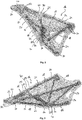
- FIG. 2 to 4 One example for a result of the second sub-step S1b is shown in Fig. 2 to 4 . It shows the body 16 with the tubular cavities 18 having the first open end 30 and second open end 32 and a complex path there between, wherein the first portions 20 made of the first polymer materials 22 are present to form the second open end 32, junction points or junction areas 40 and/or curvature sections of the tubular cavities 18.
- additional first portions 20 can also form the first open ends 30.
- the first open ends 30 are provided within the second portion 24 which surrounds and connects several first portions 20 arranged spaced apart from each other.
- the second material 26 to be removed in the third step and used as auxiliary material only is preferably the dominant material in the body 16.
- the 60% per weight, especially 70 to 95% per weight of the body is made from the second material 26, and only the rest is made from the first material.
- the part 10 will contain only 5 to 40 % of the polymer material of the body 16.
- the body 16 is used as a tool to manufacture the part 10 which is shown in Fig. 11 to 13 .
- the second portion 24 acts as a form for the tubular cavities 18 in order to inject the continuous fibres 28.
- a third material for example, a metallic material.
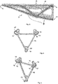
- a metallic member 44 is shown in Fig. 5 and 6 .
- the metallic member 44 has, on one side, a form that is complementary to one end of the body 16, especially complementary to one end of the second portion 24.
- the metallic member 44 has openings that can be aligned with the first open ends 30.
- the metallic member 44 can be attached to the end of the body 16 which has the first open ends 30 of the tubular cavities 18.
- the metallic member 44 has protruding portions 48 defining the openings 46 that can be engaged with recessed portions 50 of the second portion 24 defining the first open ends 30 of the tubular cavities 18.
- the first step S1 can optionally have the additional sub-steps:
- the metallic member 16 can, for example, be made by machining or other manufacturing technologies.
- the pre-assembling is done with coincident tubular cavities 18, i. e. the opening 46 are in alignment with the first open ends 30 of the tubular cavities 18.
- the assembly can be done by different technologies.
- the metallic member 44 and the body 16 can be attached to each other by positive engagement between the protruding portions 48 and the recessed portions 50.
- the different parts of the manufacturing tool 52, for example, the body 16 and the metallic member 44 can also be connected to each other, for example by gluing or bonding.
- the manufacturing tool 52 is formed by an arrangement of the body 16 and a further member such as the metallic member 44 as shown in Fig. 7 and 8 .
- the second step S2 is conducted.
- a continuous fibre injection process (CFIP) is conducted such as this is described in EP 3 231 592 A1 .
- the fibres bundles 36 are injected together with a liquid resin into the tubular cavities 18. This process is generally known from EP 3 231 592 A1 and is not described further herein.
- carbon fibres are injected with a thermoset resin.
- the fibre bundles 36 are then formed by the path of the tubular cavities 18, i. e., the fibre bundles 36 take the form of complex paths of the tubular cavities 18.
- the resin which is injected together with the fibre bundles 36 is set so that the form of the fibre bundles 36 is fixed by the resin.
- the manufacturing tool 52 is used as form to form the fibre reinforcement structure.
- the form can be chosen such that the loads in the composite truss structure 42
- not only load carrying reinforcement by using carbon fibre bundles can be integrated, but also functional fibres.
- functional fibres such as glass fibres that can be used to form a thermal and/or strain gauge or ceramic fibres that can be used to form an actuator are injected.
- the second step S2 can also include a setting of the resin.
- the manufacturing tool 52 with the injected fibre bundles 36 as well as the resin can be put in an oven (not shown) for curing the thermosetting resin.
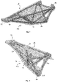
- Figs. 9 and 10 show the manufacturing tool 52 containing the injected fibre bundles 36. This manufacturing tool 52 is then put into a bath (not shown) with the solvent in order to remove the second polymer material 26 by dissolving it.
- a bath is an example for a dissolving device for dissolving the second material 26.
- the dissolution of the second polymer material 26 using a specific solvent is one preferred embodiment of the third step S3.
- the third step S3 may also include other technologies to remove the second material such as subtractive technologies.
- the second polymer material 26 can be handled similar to a sacrificial material as known in the semi-conductor component manufacturing.
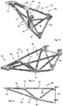
- the part 10 is achieved as shown in Fig. 11 to 13 .
- the part 10 is formed as a composite truss structure 42 with the first polymer material 22 forming junction areas 40 and/or curvature areas while the fibre bundle 36 is fixed by the resin function as truss struts.
- the metallic member 44 can be used as a fixation means to fix the composite truss structure 42 to other components.
- the part 10 achieved with the manufacturing method of Fig. 1 can be used for lightweight structure parts of air carrier or space carriers or other vehicles, such as manned or unmanned aircrafts or satellites.
- the invention provides a manufacturing method for manufacturing a part (10) made of composite material (12) with a continuous fibre reinforcement (14), the method comprising the steps:
Landscapes
- Engineering & Computer Science (AREA)
- Chemical & Material Sciences (AREA)
- Materials Engineering (AREA)
- Mechanical Engineering (AREA)
- Manufacturing & Machinery (AREA)
- Composite Materials (AREA)
- Textile Engineering (AREA)
- Physics & Mathematics (AREA)
- Optics & Photonics (AREA)
- Structural Engineering (AREA)
- Civil Engineering (AREA)
- Ceramic Engineering (AREA)
- Moulding By Coating Moulds (AREA)
- Manufacture Of Alloys Or Alloy Compounds (AREA)
Abstract
Description
- The invention relates to a manufacturing method for manufacturing a part made of composite material with a continuous fibre reinforcement. Further, the invention relates to a manufacturing system for manufacturing a part made of composite material with a continuous fibre reinforcement.
- 3D reinforced composite structures are more and more relevant for all future structural applications in vehicles and aircrafts such as urban air vehicles, satellites, HAPS, NGWS/FCAS, drones or other carriers. Especially, load adapted 3D reinforced composite structures are generic enablers for loaded lightweight structures.
- One possibility to achieve 3D reinforced composite structures is composite 3D printing of the whole reinforced composite part which is especially usable for a small-scale production. For a larger series production, manufacturing by thermo-bending and overmoulding can be used with higher investments in manufacturing tools.
-
EP 3 231 592 A1 relates to a method for manufacturing a part made from composite material, having a body and one or more continuous fibre bundles in its interior, characterised in that it comprises the stages of: - a) obtaining a body that includes one or more tubular cavities in its interior that extend between a first end, disposed on the outer surface of the body and which comprises an inlet orifice, and a second end, opposite to the first end; b) introducing resin in the liquid state and a continuous fibre bundle in the interior of at least one tubular cavity through its inlet orifice; and c) curing the resin until it solidifies, adhering to the body and fixing the continuous fibre bundle.
EP 3 231 592 A1 also relates to a system for manufacturing a part made from composite material and to the part made from composite material obtained. - The object of the invention is to enable manufacturing of more lightweight load adapted 3D reinforced composite material parts with lower tool and processing costs.
- For achieving this object, the invention provides a manufacturing method, a manufacturing system and a composite material part obtainable therewith in accordance with the independent claims. Advantageous embodiments form the subject-matter of the dependent claims.
- According to one aspect, the invention provides a manufacturing method for manufacturing a part made of composite material with a continuous fibre reinforcement, the method comprising the steps:
- a) providing a body with tubular cavities and having at least one first portion made from a first polymer material and at least one second portion made from a second polymer material;
- b) introducing resin and continuous fibres into the tubular cavities,
- c) at least partially removing the second polymer material.
- a1) selecting the second polymer material from materials that are soluble in a solvent and the first polymer material from polymer materials that are non-soluble in said solvent.
- c1) dissolving the second material in the solvent.
- c2) removing the at least one second portion.
- c3) removing all the second material from the body.
- a2) additive layer manufacturing of the body.
- a3) designing the body with first portions defining openings of the cavities.
- a4) designing the body with first portions defining curvature portions of the cavities.
- a5) designing the body with first portions defining junction areas of the continuous fibre reinforcement.
- a6) designing the body with the at least one second portion defining middle sections of the tubular cavities.
- a7) designing the body with the at least one second portion defining straight sections of the tubular cavities.
- a8) designing the body with a larger amount of second material and a smaller amount of first material.
- Preferably, at least 60% per weight, especially 70%-95% by weight, of the body are made from the second material.
- a9) designing the body with several first portions spaced apart from each other and connected by at least one second portion.
- a10) designing the body such that the at least one tubular cavity subsequently passes through the at least one first portion and the at least one second portion.
- a11) adding and/or connecting a metal member to the body such that the metal member has openings in alignment with open ends of the tubular cavities.
- b1) introducing the resin in a liquid state and a continuous fibre bundle simultaneously.
- b2) introducing a continuous fibre bundle within said at least one tubular cavity exerting on the continuous fibres a viscous drag force by means of a pressurized fluid or the resin, applying pressure differential.
- b3) introducing a continuous fibre bundle within said at least one tubular cavity exerting a mechanical pushing force on the bundle of continuous fibres.
- b4) introducing the resin and the continuous fibres sequentially, especially first the continuous fibres and subsequently the resin in a liquid state.
- b5) introducing reinforcing fibres, especially carbon fibres and/or a carbon fibre bundle.
- b6) introducing functional fibres, especially glass fibres and/or ceramic fibres.
- b7) introducing glass fibres for forming at least one thermal and/or strain gauge.
- b8) introducing ceramic fibres for forming at least one actuator. Especially, by introducing ceramic bundles for forming a fibre structure having piezoelectric properties, one or several piezoelectric actuators can be formed in the fibre structure.
- b9) curing the resin after introducing the resin and continuous fibres into the tubular cavities.
- According to a further aspect, the invention provides a composite material part, obtainable by a manufacturing method according to any of the preceding embodiments.
- Preferably, the composite material part is formed as a reinforcement fibre truss structure.
- According to another aspect, the invention provides a manufacturing system for manufacturing a part made of composite material with a continuous fibre reinforcement, comprising:
- an additive layer manufacturing device for additive layer manufacturing a body having at least a first portion from a first material which is non-soluble in a solvent and a second portion from a second material which is soluble in the solvent and at least one tubular cavity passing through the first and second portions;
- a resin and fibre introduction device for introducing resin and continuous fibres into the at least one tubular cavity; and
- a dissolving device for dissolving the second material in the solvent.
- According to another aspect, the invention provides a transport carrier or vehicle, especially a manned or unmanned aircraft or satellite, comprising a part obtained by a method according to any of the preceding embodiments and/or by using a manufacturing system according to the further aspect of the invention and/or a composite material part as described above.
- The invention relates to the field of material science and especially to a manufacturing of 3D reinforced composite structures. Preferred use for such structures obtainable by embodiments of the invention are structural applications in transport carriers and vehicles and aircrafts such as urban air vehicles, satellites, HAPS, NGWS/FCAS, drones. More generally, parts obtainable by the invention are used as basis for loaded lightweight structures.
- Embodiments of the invention especially use a continuous fibre injection process such as disclosed and described in
EP 3 231 592 A1 which is incorporated herein by reference. Embodiments of the invention provide full 3D fibre reinforcements which are seen as a missing brick for lightweight parts and that are not manufacturable up to date. - Embodiments of the invention relate to a method for producing full 3d fibre reinforced polymer composite materials by means of 3d-printed soluble manufacturing tools.
- The continuous fibre injection process has the advantage that 3D load adapted reinforced composite parts can be manufactured at low production costs with low investments in tools. Since fibres are injected with high pressure in tubular cavities in a polymer body, the body needs a polymer structure that can withstand these pressures. With the invention, it is possible to lower the weight of parts that are obtained by such a continuous fibre injection process.
- Preferred embodiments of the invention have at least one, several or all of the following advantages:
- It is possible to provide a carbon fibre UD (unidirectional) reinforcement with up to approximately 50x higher specific strength/modulus compared to high performance polymers including best resistance against creep, temperature/media, fatigue, etc.
- Loads in structures are oriented in full 3d - technics with full 3d fibre orientation capability needed.
- Beside load-carrying reinforcements, functional fibres can be integrated (such as glass fibres as thermal/strain gauges, ceramic fibres as actuators).
- Preferred embodiments of the invention provide composite structures with low polymer ratio/mass, but ideal full 3d oriented reinforcement fibres with lowest tool and processing costs feasible.
- The manufacturing method is ideal for low/medium rate series.
- Preferred embodiments of the manufacturing system comprise especially technical means for producing full 3d composite structures.
- According to a preferred embodiment a geometrical design of fibre reinforcement, polymer part material and soluble auxiliary/support material is provided.
- The geometrical design is transferred into a process path (G-code), for example via slicer software.
- The first material is especially a polymer part material (e.g. PEEK). The second material is especially a solvable support material (e.g. 3dGence ESM-10).
- Preferably, liquid resin and reinforcement/functional fibres are provided.
- Preferably, an ALM (Additive Layer Manufacturing) machine is used which is capable to process at minimum one part polymer material and one soluble material. Examples for such an ALM are FLM (Filament Layer Manufacturing) printers (available on market), modified HSS machines (HSS = High Speed Sintering; e.g. Binder Jetting with IR activation with an adapted ink) or adapted SLS machines with multi-material recoater (SLS = Selective Laser Sintering, especially feasible with two kind of materials, an example is the Aerosint re-coater, available from the company Aerosint).
- Embodiments of the system further include a Fibre injection machine (CFIP) and, eventually, an oven - in case of hot curing thermoset resin. An example of a CFIP machine is shown and described in
EP 3 231 592 A1 , incorporated herein by reference. - Embodiments of the system further provide a solvent to dissolve the support material.
- Preferred embodiments of the manufacturing method comprise the following steps:
- 1) Geometrical design of the fibre reinforcement, polymer part material (example of the first material) and surrounding auxiliary/support material (example of the second material).
- 2) Generation of the process path with conventual slicer software e.g. Simplify3d, Cura, Slic3r,...
- 3) Printing of the first and second materials in one step with fibre paths integrated as open cavities, especially tubular cavities
- 4) Surface cleaning with subtractive processes (solvents, sandblasting milling, drilling, etc.) if needed
- 5) Injection of dry fibres with liquid resin in accordance with the CFIP process and device, e.g. as described and shown in
EP 3 231 592 A1 - 6) Curing of thermoset resin in fibre reinforcements in oven if required
- 7) Dissolution of second material with subtractive technics and/or solvents (acids, water, etc.)
- 8) Finishing processes such as cutting fibre ends and/or cleaning of surface with sand-blasting, milling, grinding, solvents or others if needed.
- According to preferred embodiments a full 3d reinforced part with local polymer and load oriented "naked" fibre reinforcements is achieved.
- Preferred embodiments of the invention are described in more detail with reference to the accompanying drawings.
- Fig. 1
- a flow chart of a method for manufacturing a part made of composite material with a continuous fibre reinforcement;
- Fig. 2
- a perspective view of a body which is obtained in a first step of the manufacturing method of
Fig. 1 ; - Fig. 3
- a perspective view of the body of
Fig. 2 ; - Fig. 4
- a side view of the body of
Fig. 2 ; - Fig. 5
- a plan view of a metallic member which is optionally used in the method of
Fig. 1 ; - Fig. 6
- a perspective view of the metallic member of
Fig. 5 ; - Fig. 7
- a perspective view of the body of
Fig. 2 with a metallic member ofFig. 5 attached thereto; - Fig. 8
- a further perspective view of the arrangement of the body and the metallic member of
Fig. 7 ; - Fig. 9
- a view similar to
Fig. 7 after a further step of the manufacturing method wherein continuous fibres have been injected into the body; - Fig. 10
- another perspective view of the arrangement of
Fig. 9 with the body, the metallic member and the continuous fibres injected into the body; - Fig. 11
- a perspective view of the part manufactured with the method of
Fig. 1 with the optional metallic member; - Fig. 12
- a further perspective view of the part of
Fig. 11 ; and - Fig. 13
- a side view of the part of
Fig. 11 -
Fig. 1 is a flow chart for a manufacturing method for manufacturing apart 10 made of acomposite material 12 with acontinuous fibre reinforcement 14. An example for such apart 10 obtained or obtainable by such method is shown inFigs. 11 to 13 . - The method comprises a first step:
S1 providing a body 16 - seeFig. 2 to 4 - withtubular cavities 18 and with at least onefirst portion 20 made from afirst polymer material 22 and at least onesecond portion 24 made from asecond polymer material 26. - Further, the manufacturing method of
Fig. 1 comprises a second step:
S2 introducing resin and continuous fibres 28 - seeFig. 9 and 10 - into thetubular cavities 18 of thebody 16. - Further, the manufacturing method of
Fig. 1 comprises a third step:
S3 removing the at least onesecond portion 24. - In a preferred embodiment, the first step S1 comprises manufacturing of one or several tool parts containing
tubular cavities 18 inside. Preferably, thesecond polymer material 26 is a soluble polymer which is soluble in a specific solvent, while thefirst polymer material 22 is a non-soluble polymer that is not soluble in the specific solvent. Most preferably, thebody 16 is made by additive layer manufacturing with the non-soluble andsoluble polymers - For manufacturing of the
body 16, step S1 comprises a first sub-step:
S1a geometrical design of thefibre reinforcement 14, of thefirst polymer material 22 which shall be present in the part to be manufactured and of thesecond polymer material 26 which is only used as surrounding auxiliary or support material for the manufacturing of thepart 10 and which is removed in step S3. - For example, the design is made with CAD software.
- In the first sub-step S1a, the
body 16 is preferably designed such that eachtubular cavity 18 passes through thebody 16 from a firstopen end 30 to a secondopen end 32. - In a preferred embodiment, the
first portions 20 are designed such thatfirst portions 20 are present in areas where the continuous fibres 28 - which are injected in the second step S2 in the form of fibre bundles 36 - form a curvature and/or injunction areas 40 of thepart 10. In thejunction areas 40,different fibre bundles 36 are close to each other. In the embodiment shown, thepart 10 is acomposite truss structure 42 with truss struts formed by thecontinuous fibre bundles 36 and truss nodes formed by the junction areas. - The at least one
second portion 24 is present in all other areas of thebody 16. Especially, the at least onesecond portion 24 forms the wall of thetubular cavities 18 in middle portions thereof and/or in straight sections thereof. - Most preferably, the
tubular cavities 18 pass subsequently through afirst portion 20 and asecond portion 24. In preferred embodiments, at least one of the first and second open ends 30, 32 of atubular cavity 18 is formed by afirst portion 20. - Referring back to
Fig. 1 , the first step S1 of the manufacturing method further comprises a second sub-step:
S1b manufacturing thebody 16 using an additive layer manufacturing machine (ALM machine - not shown). - Especially, the second sub-step S1b comprises generating of a process path with conventional slicer software such as Simplify3d Cura, Slic3r, ... Especially, the design obtained by the first sub-step S1a is converted in a machine-readable form that can be read and processed by an additive layer manufacturing machine.
- As ALM machine, any ALM machine (also called 3D printer) can be used that is capable to process the first and
second polymer materials second polymer materials materials first polymer material 22 is not soluble by a solvent and thesecond material 26 is soluble by the solvent. For example, thesecond polymer material 26 is a material which is available on the market as soluble auxiliary material for supporting a 3D structure during printing and that can be removed afterwards. One example is 3dGence ESM-10. Thefirst polymer material 22 is a polymer material which can be printed and which is not soluble by the solvent which is used to remove thesecond polymer material 26. One example is PEEK. Further examples are PE, PP, ABS, PETG, ... - Examples for the ALM machine are a FLM printer (available on the market), HS machines or SLS machines.
- One example for a result of the second sub-step S1b is shown in
Fig. 2 to 4 . It shows thebody 16 with thetubular cavities 18 having the firstopen end 30 and secondopen end 32 and a complex path there between, wherein thefirst portions 20 made of thefirst polymer materials 22 are present to form the secondopen end 32, junction points orjunction areas 40 and/or curvature sections of thetubular cavities 18. In an embodiment not shown, additionalfirst portions 20 can also form the first open ends 30. In the embodiment as shown in theFig. 2 to 4 , the first open ends 30 are provided within thesecond portion 24 which surrounds and connects severalfirst portions 20 arranged spaced apart from each other. - One aim of the design of the body is to achieve a part with a very low polymer to reinforcement fibre ratio. Hence, the
second material 26 to be removed in the third step and used as auxiliary material only is preferably the dominant material in thebody 16. For example, the 60% per weight, especially 70 to 95% per weight of the body is made from thesecond material 26, and only the rest is made from the first material. Hence, thepart 10 will contain only 5 to 40 % of the polymer material of thebody 16. - The
body 16 is used as a tool to manufacture thepart 10 which is shown inFig. 11 to 13 . Thesecond portion 24 acts as a form for thetubular cavities 18 in order to inject thecontinuous fibres 28. - In the embodiment shown, it is further possible to add a third material, for example, a metallic material. An example for a
metallic member 44 is shown inFig. 5 and 6 . Themetallic member 44 has, on one side, a form that is complementary to one end of thebody 16, especially complementary to one end of thesecond portion 24. Themetallic member 44 has openings that can be aligned with the first open ends 30. Themetallic member 44 can be attached to the end of thebody 16 which has the first open ends 30 of thetubular cavities 18. - According to one example, the
metallic member 44 has protrudingportions 48 defining theopenings 46 that can be engaged with recessed portions 50 of thesecond portion 24 defining the first open ends 30 of thetubular cavities 18. - Hence, referring back to
Fig. 1 , the first step S1 can optionally have the additional sub-steps: - S1c
- manufacturing a
metallic member 44, and - S1d
- pre-assembling the
body 16 and themetallic member 44. - In the third sub-step S1c, the
metallic member 16 can, for example, be made by machining or other manufacturing technologies. - In one preferred embodiment of the fourth sub-step S1d, the pre-assembling is done with coincident
tubular cavities 18, i. e. theopening 46 are in alignment with the first open ends 30 of thetubular cavities 18. The assembly can be done by different technologies. For example, themetallic member 44 and thebody 16 can be attached to each other by positive engagement between the protrudingportions 48 and the recessed portions 50. The different parts of themanufacturing tool 52, for example, thebody 16 and themetallic member 44, can also be connected to each other, for example by gluing or bonding. - Preferably, the
manufacturing tool 52 is formed by an arrangement of thebody 16 and a further member such as themetallic member 44 as shown inFig. 7 and 8 . - After the fourth sub-step S1d of the first step S1, the second step S2 is conducted. In the second step S2, a continuous fibre injection process (CFIP) is conducted such as this is described in
EP 3 231 592 A1 . Preferably, the fibres bundles 36 are injected together with a liquid resin into thetubular cavities 18. This process is generally known fromEP 3 231 592 A1 and is not described further herein. Especially, carbon fibres are injected with a thermoset resin. The fibre bundles 36 are then formed by the path of thetubular cavities 18, i. e., the fibre bundles 36 take the form of complex paths of thetubular cavities 18. Then, the resin which is injected together with the fibre bundles 36 is set so that the form of the fibre bundles 36 is fixed by the resin. - Thus, the
manufacturing tool 52 is used as form to form the fibre reinforcement structure. - The form can be chosen such that the loads in the
composite truss structure 42 |are oriented as needed.|[CAJ1] - According to preferred embodiments, not only load carrying reinforcement by using carbon fibre bundles can be integrated, but also functional fibres. Hence, in at least one of the
tubular cavities 18, functional fibres such as glass fibres that can be used to form a thermal and/or strain gauge or ceramic fibres that can be used to form an actuator are injected. - The second step S2 can also include a setting of the resin. For achieving this, the
manufacturing tool 52 with the injectedfibre bundles 36 as well as the resin can be put in an oven (not shown) for curing the thermosetting resin. After the second step S2 a structure shown inFig. 9 and 10 is obtained. -
Figs. 9 and 10 show themanufacturing tool 52 containing the injected fibre bundles 36. Thismanufacturing tool 52 is then put into a bath (not shown) with the solvent in order to remove thesecond polymer material 26 by dissolving it. Such a bath is an example for a dissolving device for dissolving thesecond material 26. - Hence, the dissolution of the
second polymer material 26 using a specific solvent is one preferred embodiment of the third step S3. The third step S3 may also include other technologies to remove the second material such as subtractive technologies. Especially, thesecond polymer material 26 can be handled similar to a sacrificial material as known in the semi-conductor component manufacturing. - After removal of the
second material 26, thepart 10 is achieved as shown inFig. 11 to 13 . In this particular embodiment, thepart 10 is formed as acomposite truss structure 42 with thefirst polymer material 22 formingjunction areas 40 and/or curvature areas while thefibre bundle 36 is fixed by the resin function as truss struts. - As visible from
Fig. 11 to 13 , themetallic member 44 can be used as a fixation means to fix thecomposite truss structure 42 to other components. - Especially, the
part 10 achieved with the manufacturing method ofFig. 1 can be used for lightweight structure parts of air carrier or space carriers or other vehicles, such as manned or unmanned aircrafts or satellites. - In order to achieve a composite material part (10) with a fully load adapted 3D fibre reinforcement with low costs for tools and process, the invention provides a manufacturing method for manufacturing a part (10) made of composite material (12) with a continuous fibre reinforcement (14), the method comprising the steps:
- a) providing a body (16) with tubular cavities (18) and having at least one first portion (20) made from a first polymer material (22) and at least one second portion (24) made from a second polymer material (26);
- b) introducing resin and continuous fibres (28) into the tubular cavities (18),
- c) removing at least a part of the second polymer material (26).
-
- 10
- part
- 12
- composite material
- 14
- continuous fibre reinforcement
- 16
- body
- 18
- tubular cavity
- 20
- first portion
- 22
- first polymer material
- 24
- second portion
- 26
- second polymer material
- 28
- continuous fibre
- 30
- first open end
- 32
- second open end
- 36
- fibre bundle
- 40
- junction area
- 42
- composite truss structure
- 44
- metallic member
- 46
- openings
- 48
- protruding portions
- 50
- recessed portions
- 52
- manufacturing tool (
e.g. body 16 and metallic member 44) - S1
- Providing body with first and second portions, made from first and second materials, respectively
- S1a
- geometrically designing of fibre reinforcement and the first and second portions
- S1b
- manufacturing the body using additive layer manufacturing
- S1c
- manufacturing a metallic member
- S1d
- preassembling different parts of the body or of the body and a further member
- S2
- Introducing resin and continuous fibres into tubular cavities of body
- S3
- Removing the at least one second portion
Claims (8)
- Manufacturing method for manufacturing a part (10) made of composite material (12) with a continuous fibre reinforcement (14), the method comprising the steps:a) providing a body (16) with tubular cavities (18) and having at least one first portion made from a first polymer material (22) and at least one second portion (24) made from a second polymer material (26);b) introducing resin and continuous fibres (28) into the tubular cavities (18),c) at least partially removing the second polymer material (26).wherein step a) comprises:
a1) selecting the second polymer material (26) from materials that are soluble in a solvent and the first polymer material (22) from polymer materials that are non-soluble in the solvent and; and
wherein step c) comprises:
c1) dissolving the second material in the solvent. - Manufacturing method according to claim 1,
characterized in that step a) comprises at least one or several of the following steps:a2) additive layer manufacturing of the body (16);a3) designing the body (16) with first portions (20) defining open ends (32) of the tubular cavities (18);a4) designing the body (16) with first portions (20) defining curvature portions of the tubular cavities (18);a5) designing the body (16) with first portions (20) defining junction areas (40) of the continuous fibre reinforcement (14);a6) designing the body (16) with the at least one second portion (24) defining middle sections of the tubular cavities (18);a7) designing the body (16) with the at least one second portion (24) defining straight sections of the tubular cavities (18);a8) designing the body (16) with a larger amount of second material and a smaller amount of first material;a9) designing the body (16) with several first portions (20) spaced apart from each other and connected by at least one second portion (24);a10) designing the body (16) such that the at least one tubular cavity (18) subsequently passes through the at least one first portion (20) and the at least one second portion (24);a11) adding and/or connecting a metallic member (44) to the body (16) such that the metallic member (44) has openings (46) in alignment with open ends (30, 32) of the tubular cavities (18). - Manufacturing method according to any of the preceding claims, characterized in that step b) comprises at least one or several of the following steps:b1) introducing resin in a liquid state and a continuous fibre bundle (36) simultaneously,b2) introducing a continuous fibre bundle (36) within said at least one tubular cavity (18) exerting on the continuous fibres (28) a viscous drag force by means of a pressurized fluid or the resin, applying pressure differential;b3) introducing a continuous fibre bundle (36) within said at least one tubular cavity (18) exerting a mechanical pushing force on the bundle of continuous fibres (28);b4) introducing the resin and the continuous fibres (28) sequentially, especially first the continuous fibres (28) and subsequently the resin in a liquid stateb5) introducing reinforcing fibres, especially carbon fibres and/or a carbon fibre bundle (36);b6) introducing functional fibres, especially glass fibres and/or ceramic fibres;b7) introducing glass fibres for forming at least one thermal and/or strain gauge;b8) introducing ceramic fibres for forming at least one actuator;b9) curing the resin after introducing the resin and continuous fibres (28) into the tubular cavities (18).
- Manufacturing method according to any of the preceding claims, characterized in that step c) comprises at least one or several of the following steps:c2) removing the at least one second portion (24);c3) removing all the second material (26) from the body (16)c4) removing a connecting section or connection sections of the body connecting at least two of the first portions (20) so that the first portions (20) are spaced apart from each other.
- Composite material part, obtainable by a manufacturing method according to any of the preceding claims.
- Composite material part according to claim 5, formed as a reinforcement fibre truss structure.
- Manufacturing system for manufacturing a part (10) made of composite material (12) with a continuous fibre reinforcement (14), comprising:an additive layer manufacturing device for additive layer manufacturing a body having at least a first portion (20) from a first material and a second portion (24) from a second material wherein the second material is soluble in a solvent and the first material is non-soluble in the solvent and at least one tubular cavity (18) passing through the first and second portions (20, 24);a resin and fibre introduction device for introducing resin and continuous fibres (28) into the at least one tubular cavity (18); anda dissolving device for dissolving the second material in the solvent.
- Transport carrier or vehicle, especially manned or unmanned aircraft or satellite, comprising a part obtained by a method according to any of the claims 1 to 4 and/or by using a manufacturing system according to claim 7 and/or a composite material part according to any of the claims 5 or 6.
Priority Applications (7)
| Application Number | Priority Date | Filing Date | Title |
|---|---|---|---|
| EP19380014.1A EP3769945B1 (en) | 2019-07-25 | 2019-07-25 | Manufacturing method and system for manufacturing a continuous fibre reinforced composite part |
| ES19380014T ES2945568T3 (en) | 2019-07-25 | 2019-07-25 | Manufacturing method and system for manufacturing a continuous fiber-reinforced composite part |
| PCT/EP2020/070815 WO2021013935A1 (en) | 2019-07-25 | 2020-07-23 | Manufacturing method and system for manufacturing a continuous fibre reinforced composite part |
| KR1020227002002A KR20220039711A (en) | 2019-07-25 | 2020-07-23 | Manufacturing method and manufacturing system of continuous fiber-reinforced composite parts |
| CN202080053007.3A CN114585501A (en) | 2019-07-25 | 2020-07-23 | Manufacturing method and system for manufacturing continuous fiber reinforced composite parts |
| US17/629,894 US12275206B2 (en) | 2019-07-25 | 2020-07-23 | Manufacturing method and system for manufacturing a continuous fiber reinforced composite part |
| JP2022504236A JP7649774B2 (en) | 2019-07-25 | 2020-07-23 | Manufacturing method and system for manufacturing continuous fiber reinforced composite parts |
Applications Claiming Priority (1)
| Application Number | Priority Date | Filing Date | Title |
|---|---|---|---|
| EP19380014.1A EP3769945B1 (en) | 2019-07-25 | 2019-07-25 | Manufacturing method and system for manufacturing a continuous fibre reinforced composite part |
Publications (2)
| Publication Number | Publication Date |
|---|---|
| EP3769945A1 true EP3769945A1 (en) | 2021-01-27 |
| EP3769945B1 EP3769945B1 (en) | 2023-02-22 |
Family
ID=67620362
Family Applications (1)
| Application Number | Title | Priority Date | Filing Date |
|---|---|---|---|
| EP19380014.1A Active EP3769945B1 (en) | 2019-07-25 | 2019-07-25 | Manufacturing method and system for manufacturing a continuous fibre reinforced composite part |
Country Status (7)
| Country | Link |
|---|---|
| US (1) | US12275206B2 (en) |
| EP (1) | EP3769945B1 (en) |
| JP (1) | JP7649774B2 (en) |
| KR (1) | KR20220039711A (en) |
| CN (1) | CN114585501A (en) |
| ES (1) | ES2945568T3 (en) |
| WO (1) | WO2021013935A1 (en) |
Cited By (1)
| Publication number | Priority date | Publication date | Assignee | Title |
|---|---|---|---|---|
| US11673350B2 (en) | 2020-04-07 | 2023-06-13 | Airbus (S.A.S.) | Production method and production system for producing a continuous-fiber-reinforced component |
Families Citing this family (3)
| Publication number | Priority date | Publication date | Assignee | Title |
|---|---|---|---|---|
| EP3839796B1 (en) * | 2019-12-16 | 2026-01-07 | Dassault Systèmes | Designing a 3d modeled object via orientation optimization |
| US12229476B2 (en) * | 2021-04-21 | 2025-02-18 | Autodesk, Inc. | Computer aided generative design with modal analysis driven shape modification process |
| EP4686555A1 (en) * | 2024-08-01 | 2026-02-04 | Reinforce3D, S.L. | An injector apparatus and a kit for an injector apparatus |
Citations (3)
| Publication number | Priority date | Publication date | Assignee | Title |
|---|---|---|---|---|
| US20140193192A1 (en) * | 2011-07-20 | 2014-07-10 | Daimler Ag | Connecting Structure for a Motor Vehicle and Method for Producing Same |
| US20150190965A1 (en) * | 2014-01-09 | 2015-07-09 | Seiko Epson Corporation | Three-dimensional shaped article manufacturing method, three-dimensional shaped article manufacturing apparatus, ink set, and three-dimensional shaped article |
| EP3231592A1 (en) | 2014-12-12 | 2017-10-18 | Fundació Eurecat | Method and system for manufacturing a part from composite material and part obtained thereby |
Family Cites Families (3)
| Publication number | Priority date | Publication date | Assignee | Title |
|---|---|---|---|---|
| DK3429832T3 (en) | 2016-03-14 | 2021-11-22 | Addifab Aps | ADDITIVE MANUFACTURING DEVICE AND SYSTEM FOR MANUFACTURING A SACRIFICE FORM FORMING AN OBJECT |
| EP3823773A4 (en) | 2017-05-01 | 2022-06-22 | Tritone Technologies Ltd. | METHOD AND APPARATUS FOR MOLDING, APPLICABLE IN PARTICULAR TO METAL AND/OR CERAMIC |
| US10814564B2 (en) * | 2017-10-11 | 2020-10-27 | Divergent Technologies, Inc. | Composite material inlay in additively manufactured structures |
-
2019
- 2019-07-25 ES ES19380014T patent/ES2945568T3/en active Active
- 2019-07-25 EP EP19380014.1A patent/EP3769945B1/en active Active
-
2020
- 2020-07-23 KR KR1020227002002A patent/KR20220039711A/en active Pending
- 2020-07-23 CN CN202080053007.3A patent/CN114585501A/en active Pending
- 2020-07-23 JP JP2022504236A patent/JP7649774B2/en active Active
- 2020-07-23 WO PCT/EP2020/070815 patent/WO2021013935A1/en not_active Ceased
- 2020-07-23 US US17/629,894 patent/US12275206B2/en active Active
Patent Citations (3)
| Publication number | Priority date | Publication date | Assignee | Title |
|---|---|---|---|---|
| US20140193192A1 (en) * | 2011-07-20 | 2014-07-10 | Daimler Ag | Connecting Structure for a Motor Vehicle and Method for Producing Same |
| US20150190965A1 (en) * | 2014-01-09 | 2015-07-09 | Seiko Epson Corporation | Three-dimensional shaped article manufacturing method, three-dimensional shaped article manufacturing apparatus, ink set, and three-dimensional shaped article |
| EP3231592A1 (en) | 2014-12-12 | 2017-10-18 | Fundació Eurecat | Method and system for manufacturing a part from composite material and part obtained thereby |
Cited By (2)
| Publication number | Priority date | Publication date | Assignee | Title |
|---|---|---|---|---|
| US11673350B2 (en) | 2020-04-07 | 2023-06-13 | Airbus (S.A.S.) | Production method and production system for producing a continuous-fiber-reinforced component |
| EP4628289A1 (en) | 2020-04-07 | 2025-10-08 | Airbus (S.A.S.) | Method for producing a continuous fibre-reinforced component |
Also Published As
| Publication number | Publication date |
|---|---|
| US20220250342A1 (en) | 2022-08-11 |
| CN114585501A (en) | 2022-06-03 |
| JP2022542870A (en) | 2022-10-07 |
| US12275206B2 (en) | 2025-04-15 |
| JP7649774B2 (en) | 2025-03-21 |
| ES2945568T3 (en) | 2023-07-04 |
| WO2021013935A1 (en) | 2021-01-28 |
| KR20220039711A (en) | 2022-03-29 |
| EP3769945B1 (en) | 2023-02-22 |
Similar Documents
| Publication | Publication Date | Title |
|---|---|---|
| US12275206B2 (en) | Manufacturing method and system for manufacturing a continuous fiber reinforced composite part | |
| CN111069598B (en) | Method and apparatus for manufacturing optimized panels and other composite structures | |
| US11155031B2 (en) | 5-axis continuous carbon fiber 3D printing and meta-materials, parts, structures, systems, and design methods thereby enabled | |
| US11548242B2 (en) | Multi-planar fiber matrix tool-less preform for resin infusion | |
| US8844877B1 (en) | Stay sharp, fail safe leading edge configuration for hypersonic and space access vehicles | |
| US8337740B2 (en) | Reinforced internal composite structures | |
| US11584094B2 (en) | Composite material inlay in additively manufactured structures | |
| US20100121475A1 (en) | Method of manufacturing co-molded inserts | |
| US8465084B2 (en) | Bodyshell structure for a motor vehicle and method for the production thereof | |
| Nordin et al. | Advances in high temperature materials for additive manufacturing | |
| EP3231586B1 (en) | Structure having joined unitary structures | |
| EP2785503B1 (en) | Method for producing a mold, and mold so produced | |
| US7858012B2 (en) | Automated prototyping of a composite airframe | |
| US10836120B2 (en) | Hybrid composite structures with integrated 3-D printed elements | |
| Tiwari et al. | Advanced fabrication techniques of composites: a state of art review and future applications | |
| Türk et al. | Design and manufacture of hybrid metal composite structures using functional tooling made by additive manufacturing | |
| Samal et al. | 3D-Printed Satellite Brackets: Materials, Manufacturing and Applications. Crystals 2022, 12, 1148 | |
| Rehkopf | Automotive carbon fiber composites | |
| Vizzini | Design, Tooling, and Manufacturing Interaction | |
| BENCZE | STUDY ON THE USE OF 3D PRINTED PARTS FOR AIRCRAFTS AND DRONES. |
Legal Events
| Date | Code | Title | Description |
|---|---|---|---|
| PUAI | Public reference made under article 153(3) epc to a published international application that has entered the european phase |
Free format text: ORIGINAL CODE: 0009012 |
|
| STAA | Information on the status of an ep patent application or granted ep patent |
Free format text: STATUS: THE APPLICATION HAS BEEN PUBLISHED |
|
| AK | Designated contracting states |
Kind code of ref document: A1 Designated state(s): AL AT BE BG CH CY CZ DE DK EE ES FI FR GB GR HR HU IE IS IT LI LT LU LV MC MK MT NL NO PL PT RO RS SE SI SK SM TR |
|
| AX | Request for extension of the european patent |
Extension state: BA ME |
|
| STAA | Information on the status of an ep patent application or granted ep patent |
Free format text: STATUS: REQUEST FOR EXAMINATION WAS MADE |
|
| 17P | Request for examination filed |
Effective date: 20210609 |
|
| RBV | Designated contracting states (corrected) |
Designated state(s): AL AT BE BG CH CY CZ DE DK EE ES FI FR GB GR HR HU IE IS IT LI LT LU LV MC MK MT NL NO PL PT RO RS SE SI SK SM TR |
|
| RIC1 | Information provided on ipc code assigned before grant |
Ipc: B29L 31/30 20060101ALN20220802BHEP Ipc: B33Y 80/00 20150101ALI20220802BHEP Ipc: B33Y 70/10 20200101ALI20220802BHEP Ipc: B29C 64/40 20170101ALI20220802BHEP Ipc: B29C 33/52 20060101ALI20220802BHEP Ipc: B29C 70/20 20060101AFI20220802BHEP |
|
| GRAP | Despatch of communication of intention to grant a patent |
Free format text: ORIGINAL CODE: EPIDOSNIGR1 |
|
| STAA | Information on the status of an ep patent application or granted ep patent |
Free format text: STATUS: GRANT OF PATENT IS INTENDED |
|
| INTG | Intention to grant announced |
Effective date: 20220912 |
|
| GRAS | Grant fee paid |
Free format text: ORIGINAL CODE: EPIDOSNIGR3 |
|
| GRAA | (expected) grant |
Free format text: ORIGINAL CODE: 0009210 |
|
| STAA | Information on the status of an ep patent application or granted ep patent |
Free format text: STATUS: THE PATENT HAS BEEN GRANTED |
|
| AK | Designated contracting states |
Kind code of ref document: B1 Designated state(s): AL AT BE BG CH CY CZ DE DK EE ES FI FR GB GR HR HU IE IS IT LI LT LU LV MC MK MT NL NO PL PT RO RS SE SI SK SM TR |
|
| REG | Reference to a national code |
Ref country code: GB Ref legal event code: FG4D |
|
| REG | Reference to a national code |
Ref country code: CH Ref legal event code: EP |
|
| REG | Reference to a national code |
Ref country code: AT Ref legal event code: REF Ref document number: 1549258 Country of ref document: AT Kind code of ref document: T Effective date: 20230315 Ref country code: IE Ref legal event code: FG4D |
|
| REG | Reference to a national code |
Ref country code: DE Ref legal event code: R096 Ref document number: 602019025506 Country of ref document: DE |
|
| REG | Reference to a national code |
Ref country code: LT Ref legal event code: MG9D |
|
| REG | Reference to a national code |
Ref country code: NL Ref legal event code: MP Effective date: 20230222 |
|
| REG | Reference to a national code |
Ref country code: ES Ref legal event code: FG2A Ref document number: 2945568 Country of ref document: ES Kind code of ref document: T3 Effective date: 20230704 |
|
| REG | Reference to a national code |
Ref country code: AT Ref legal event code: MK05 Ref document number: 1549258 Country of ref document: AT Kind code of ref document: T Effective date: 20230222 |
|
| REG | Reference to a national code |
Ref country code: BE Ref legal event code: PD Owner name: FUNDACIO EURECAT; ES Free format text: DETAILS ASSIGNMENT: CHANGE OF OWNER(S), ASSIGNMENT; FORMER OWNER NAME: AIRBUS DEFENCE AND SPACE GMBH Effective date: 20230614 |
|
| PG25 | Lapsed in a contracting state [announced via postgrant information from national office to epo] |
Ref country code: RS Free format text: LAPSE BECAUSE OF FAILURE TO SUBMIT A TRANSLATION OF THE DESCRIPTION OR TO PAY THE FEE WITHIN THE PRESCRIBED TIME-LIMIT Effective date: 20230222 Ref country code: PT Free format text: LAPSE BECAUSE OF FAILURE TO SUBMIT A TRANSLATION OF THE DESCRIPTION OR TO PAY THE FEE WITHIN THE PRESCRIBED TIME-LIMIT Effective date: 20230622 Ref country code: NO Free format text: LAPSE BECAUSE OF FAILURE TO SUBMIT A TRANSLATION OF THE DESCRIPTION OR TO PAY THE FEE WITHIN THE PRESCRIBED TIME-LIMIT Effective date: 20230522 Ref country code: NL Free format text: LAPSE BECAUSE OF FAILURE TO SUBMIT A TRANSLATION OF THE DESCRIPTION OR TO PAY THE FEE WITHIN THE PRESCRIBED TIME-LIMIT Effective date: 20230222 Ref country code: LV Free format text: LAPSE BECAUSE OF FAILURE TO SUBMIT A TRANSLATION OF THE DESCRIPTION OR TO PAY THE FEE WITHIN THE PRESCRIBED TIME-LIMIT Effective date: 20230222 Ref country code: LT Free format text: LAPSE BECAUSE OF FAILURE TO SUBMIT A TRANSLATION OF THE DESCRIPTION OR TO PAY THE FEE WITHIN THE PRESCRIBED TIME-LIMIT Effective date: 20230222 Ref country code: HR Free format text: LAPSE BECAUSE OF FAILURE TO SUBMIT A TRANSLATION OF THE DESCRIPTION OR TO PAY THE FEE WITHIN THE PRESCRIBED TIME-LIMIT Effective date: 20230222 Ref country code: AT Free format text: LAPSE BECAUSE OF FAILURE TO SUBMIT A TRANSLATION OF THE DESCRIPTION OR TO PAY THE FEE WITHIN THE PRESCRIBED TIME-LIMIT Effective date: 20230222 |
|
| PG25 | Lapsed in a contracting state [announced via postgrant information from national office to epo] |
Ref country code: SE Free format text: LAPSE BECAUSE OF FAILURE TO SUBMIT A TRANSLATION OF THE DESCRIPTION OR TO PAY THE FEE WITHIN THE PRESCRIBED TIME-LIMIT Effective date: 20230222 Ref country code: PL Free format text: LAPSE BECAUSE OF FAILURE TO SUBMIT A TRANSLATION OF THE DESCRIPTION OR TO PAY THE FEE WITHIN THE PRESCRIBED TIME-LIMIT Effective date: 20230222 Ref country code: IS Free format text: LAPSE BECAUSE OF FAILURE TO SUBMIT A TRANSLATION OF THE DESCRIPTION OR TO PAY THE FEE WITHIN THE PRESCRIBED TIME-LIMIT Effective date: 20230622 Ref country code: GR Free format text: LAPSE BECAUSE OF FAILURE TO SUBMIT A TRANSLATION OF THE DESCRIPTION OR TO PAY THE FEE WITHIN THE PRESCRIBED TIME-LIMIT Effective date: 20230523 Ref country code: FI Free format text: LAPSE BECAUSE OF FAILURE TO SUBMIT A TRANSLATION OF THE DESCRIPTION OR TO PAY THE FEE WITHIN THE PRESCRIBED TIME-LIMIT Effective date: 20230222 |
|
| PG25 | Lapsed in a contracting state [announced via postgrant information from national office to epo] |
Ref country code: SM Free format text: LAPSE BECAUSE OF FAILURE TO SUBMIT A TRANSLATION OF THE DESCRIPTION OR TO PAY THE FEE WITHIN THE PRESCRIBED TIME-LIMIT Effective date: 20230222 Ref country code: RO Free format text: LAPSE BECAUSE OF FAILURE TO SUBMIT A TRANSLATION OF THE DESCRIPTION OR TO PAY THE FEE WITHIN THE PRESCRIBED TIME-LIMIT Effective date: 20230222 Ref country code: EE Free format text: LAPSE BECAUSE OF FAILURE TO SUBMIT A TRANSLATION OF THE DESCRIPTION OR TO PAY THE FEE WITHIN THE PRESCRIBED TIME-LIMIT Effective date: 20230222 Ref country code: DK Free format text: LAPSE BECAUSE OF FAILURE TO SUBMIT A TRANSLATION OF THE DESCRIPTION OR TO PAY THE FEE WITHIN THE PRESCRIBED TIME-LIMIT Effective date: 20230222 Ref country code: CZ Free format text: LAPSE BECAUSE OF FAILURE TO SUBMIT A TRANSLATION OF THE DESCRIPTION OR TO PAY THE FEE WITHIN THE PRESCRIBED TIME-LIMIT Effective date: 20230222 |
|
| REG | Reference to a national code |
Ref country code: DE Ref legal event code: R097 Ref document number: 602019025506 Country of ref document: DE |
|
| PG25 | Lapsed in a contracting state [announced via postgrant information from national office to epo] |
Ref country code: SK Free format text: LAPSE BECAUSE OF FAILURE TO SUBMIT A TRANSLATION OF THE DESCRIPTION OR TO PAY THE FEE WITHIN THE PRESCRIBED TIME-LIMIT Effective date: 20230222 |
|
| PLBE | No opposition filed within time limit |
Free format text: ORIGINAL CODE: 0009261 |
|
| STAA | Information on the status of an ep patent application or granted ep patent |
Free format text: STATUS: NO OPPOSITION FILED WITHIN TIME LIMIT |
|
| 26N | No opposition filed |
Effective date: 20231123 |
|
| PG25 | Lapsed in a contracting state [announced via postgrant information from national office to epo] |
Ref country code: SI Free format text: LAPSE BECAUSE OF FAILURE TO SUBMIT A TRANSLATION OF THE DESCRIPTION OR TO PAY THE FEE WITHIN THE PRESCRIBED TIME-LIMIT Effective date: 20230222 |
|
| PG25 | Lapsed in a contracting state [announced via postgrant information from national office to epo] |
Ref country code: MC Free format text: LAPSE BECAUSE OF FAILURE TO SUBMIT A TRANSLATION OF THE DESCRIPTION OR TO PAY THE FEE WITHIN THE PRESCRIBED TIME-LIMIT Effective date: 20230222 |
|
| PG25 | Lapsed in a contracting state [announced via postgrant information from national office to epo] |
Ref country code: MC Free format text: LAPSE BECAUSE OF FAILURE TO SUBMIT A TRANSLATION OF THE DESCRIPTION OR TO PAY THE FEE WITHIN THE PRESCRIBED TIME-LIMIT Effective date: 20230222 |
|
| PG25 | Lapsed in a contracting state [announced via postgrant information from national office to epo] |
Ref country code: LU Free format text: LAPSE BECAUSE OF NON-PAYMENT OF DUE FEES Effective date: 20230725 |
|
| PG25 | Lapsed in a contracting state [announced via postgrant information from national office to epo] |
Ref country code: LU Free format text: LAPSE BECAUSE OF NON-PAYMENT OF DUE FEES Effective date: 20230725 |
|
| REG | Reference to a national code |
Ref country code: ES Ref legal event code: PC2A Owner name: FUNDACIO EURECAT Effective date: 20240911 |
|
| PG25 | Lapsed in a contracting state [announced via postgrant information from national office to epo] |
Ref country code: BG Free format text: LAPSE BECAUSE OF FAILURE TO SUBMIT A TRANSLATION OF THE DESCRIPTION OR TO PAY THE FEE WITHIN THE PRESCRIBED TIME-LIMIT Effective date: 20230222 |
|
| PG25 | Lapsed in a contracting state [announced via postgrant information from national office to epo] |
Ref country code: BG Free format text: LAPSE BECAUSE OF FAILURE TO SUBMIT A TRANSLATION OF THE DESCRIPTION OR TO PAY THE FEE WITHIN THE PRESCRIBED TIME-LIMIT Effective date: 20230222 |
|
| PG25 | Lapsed in a contracting state [announced via postgrant information from national office to epo] |
Ref country code: CY Free format text: LAPSE BECAUSE OF FAILURE TO SUBMIT A TRANSLATION OF THE DESCRIPTION OR TO PAY THE FEE WITHIN THE PRESCRIBED TIME-LIMIT; INVALID AB INITIO Effective date: 20190725 |
|
| PG25 | Lapsed in a contracting state [announced via postgrant information from national office to epo] |
Ref country code: HU Free format text: LAPSE BECAUSE OF FAILURE TO SUBMIT A TRANSLATION OF THE DESCRIPTION OR TO PAY THE FEE WITHIN THE PRESCRIBED TIME-LIMIT; INVALID AB INITIO Effective date: 20190725 |
|
| PGFP | Annual fee paid to national office [announced via postgrant information from national office to epo] |
Ref country code: ES Payment date: 20250819 Year of fee payment: 7 |
|
| PGFP | Annual fee paid to national office [announced via postgrant information from national office to epo] |
Ref country code: DE Payment date: 20250919 Year of fee payment: 7 |
|
| PGFP | Annual fee paid to national office [announced via postgrant information from national office to epo] |
Ref country code: IT Payment date: 20250731 Year of fee payment: 7 |
|
| PGFP | Annual fee paid to national office [announced via postgrant information from national office to epo] |
Ref country code: BE Payment date: 20250722 Year of fee payment: 7 Ref country code: GB Payment date: 20250724 Year of fee payment: 7 |
|
| PGFP | Annual fee paid to national office [announced via postgrant information from national office to epo] |
Ref country code: FR Payment date: 20250723 Year of fee payment: 7 |
|
| PGFP | Annual fee paid to national office [announced via postgrant information from national office to epo] |
Ref country code: CH Payment date: 20250801 Year of fee payment: 7 |
|
| PGFP | Annual fee paid to national office [announced via postgrant information from national office to epo] |
Ref country code: IE Payment date: 20250724 Year of fee payment: 7 |
|
| PG25 | Lapsed in a contracting state [announced via postgrant information from national office to epo] |
Ref country code: TR Free format text: LAPSE BECAUSE OF FAILURE TO SUBMIT A TRANSLATION OF THE DESCRIPTION OR TO PAY THE FEE WITHIN THE PRESCRIBED TIME-LIMIT Effective date: 20230222 |