EP3769664B1 - Flexible catheter-based in vivo detection device and system - Google Patents
Flexible catheter-based in vivo detection device and system Download PDFInfo
- Publication number
- EP3769664B1 EP3769664B1 EP19893259.2A EP19893259A EP3769664B1 EP 3769664 B1 EP3769664 B1 EP 3769664B1 EP 19893259 A EP19893259 A EP 19893259A EP 3769664 B1 EP3769664 B1 EP 3769664B1
- Authority
- EP
- European Patent Office
- Prior art keywords
- circuit board
- detection
- conducting material
- lighting
- component
- Prior art date
- Legal status (The legal status is an assumption and is not a legal conclusion. Google has not performed a legal analysis and makes no representation as to the accuracy of the status listed.)
- Active
Links
Images
Classifications
-
- A—HUMAN NECESSITIES
- A61—MEDICAL OR VETERINARY SCIENCE; HYGIENE
- A61B—DIAGNOSIS; SURGERY; IDENTIFICATION
- A61B1/00—Instruments for performing medical examinations of the interior of cavities or tubes of the body by visual or photographical inspection, e.g. endoscopes; Illuminating arrangements therefor
- A61B1/04—Instruments for performing medical examinations of the interior of cavities or tubes of the body by visual or photographical inspection, e.g. endoscopes; Illuminating arrangements therefor combined with photographic or television appliances
- A61B1/05—Instruments for performing medical examinations of the interior of cavities or tubes of the body by visual or photographical inspection, e.g. endoscopes; Illuminating arrangements therefor combined with photographic or television appliances characterised by the image sensor, e.g. camera, being in the distal end portion
- A61B1/051—Details of CCD assembly
-
- A—HUMAN NECESSITIES
- A61—MEDICAL OR VETERINARY SCIENCE; HYGIENE
- A61B—DIAGNOSIS; SURGERY; IDENTIFICATION
- A61B1/00—Instruments for performing medical examinations of the interior of cavities or tubes of the body by visual or photographical inspection, e.g. endoscopes; Illuminating arrangements therefor
- A61B1/00064—Constructional details of the endoscope body
- A61B1/0011—Manufacturing of endoscope parts
-
- A—HUMAN NECESSITIES
- A61—MEDICAL OR VETERINARY SCIENCE; HYGIENE
- A61B—DIAGNOSIS; SURGERY; IDENTIFICATION
- A61B1/00—Instruments for performing medical examinations of the interior of cavities or tubes of the body by visual or photographical inspection, e.g. endoscopes; Illuminating arrangements therefor
- A61B1/00112—Connection or coupling means
- A61B1/00121—Connectors, fasteners and adapters, e.g. on the endoscope handle
- A61B1/00124—Connectors, fasteners and adapters, e.g. on the endoscope handle electrical, e.g. electrical plug-and-socket connection
-
- A—HUMAN NECESSITIES
- A61—MEDICAL OR VETERINARY SCIENCE; HYGIENE
- A61B—DIAGNOSIS; SURGERY; IDENTIFICATION
- A61B1/00—Instruments for performing medical examinations of the interior of cavities or tubes of the body by visual or photographical inspection, e.g. endoscopes; Illuminating arrangements therefor
- A61B1/012—Instruments for performing medical examinations of the interior of cavities or tubes of the body by visual or photographical inspection, e.g. endoscopes; Illuminating arrangements therefor characterised by internal passages or accessories therefor
- A61B1/018—Instruments for performing medical examinations of the interior of cavities or tubes of the body by visual or photographical inspection, e.g. endoscopes; Illuminating arrangements therefor characterised by internal passages or accessories therefor for receiving instruments
-
- A—HUMAN NECESSITIES
- A61—MEDICAL OR VETERINARY SCIENCE; HYGIENE
- A61B—DIAGNOSIS; SURGERY; IDENTIFICATION
- A61B1/00—Instruments for performing medical examinations of the interior of cavities or tubes of the body by visual or photographical inspection, e.g. endoscopes; Illuminating arrangements therefor
- A61B1/06—Instruments for performing medical examinations of the interior of cavities or tubes of the body by visual or photographical inspection, e.g. endoscopes; Illuminating arrangements therefor with illuminating arrangements
- A61B1/0661—Endoscope light sources
- A61B1/0676—Endoscope light sources at distal tip of an endoscope
-
- A—HUMAN NECESSITIES
- A61—MEDICAL OR VETERINARY SCIENCE; HYGIENE
- A61B—DIAGNOSIS; SURGERY; IDENTIFICATION
- A61B1/00—Instruments for performing medical examinations of the interior of cavities or tubes of the body by visual or photographical inspection, e.g. endoscopes; Illuminating arrangements therefor
- A61B1/06—Instruments for performing medical examinations of the interior of cavities or tubes of the body by visual or photographical inspection, e.g. endoscopes; Illuminating arrangements therefor with illuminating arrangements
- A61B1/07—Instruments for performing medical examinations of the interior of cavities or tubes of the body by visual or photographical inspection, e.g. endoscopes; Illuminating arrangements therefor with illuminating arrangements using light-conductive means, e.g. optical fibres
-
- A—HUMAN NECESSITIES
- A61—MEDICAL OR VETERINARY SCIENCE; HYGIENE
- A61B—DIAGNOSIS; SURGERY; IDENTIFICATION
- A61B1/00—Instruments for performing medical examinations of the interior of cavities or tubes of the body by visual or photographical inspection, e.g. endoscopes; Illuminating arrangements therefor
- A61B1/00112—Connection or coupling means
- A61B1/00114—Electrical cables in or with an endoscope
-
- A—HUMAN NECESSITIES
- A61—MEDICAL OR VETERINARY SCIENCE; HYGIENE
- A61B—DIAGNOSIS; SURGERY; IDENTIFICATION
- A61B1/00—Instruments for performing medical examinations of the interior of cavities or tubes of the body by visual or photographical inspection, e.g. endoscopes; Illuminating arrangements therefor
- A61B1/00112—Connection or coupling means
- A61B1/00119—Tubes or pipes in or with an endoscope
-
- A—HUMAN NECESSITIES
- A61—MEDICAL OR VETERINARY SCIENCE; HYGIENE
- A61B—DIAGNOSIS; SURGERY; IDENTIFICATION
- A61B1/00—Instruments for performing medical examinations of the interior of cavities or tubes of the body by visual or photographical inspection, e.g. endoscopes; Illuminating arrangements therefor
- A61B1/005—Flexible endoscopes
-
- A—HUMAN NECESSITIES
- A61—MEDICAL OR VETERINARY SCIENCE; HYGIENE
- A61B—DIAGNOSIS; SURGERY; IDENTIFICATION
- A61B1/00—Instruments for performing medical examinations of the interior of cavities or tubes of the body by visual or photographical inspection, e.g. endoscopes; Illuminating arrangements therefor
- A61B1/06—Instruments for performing medical examinations of the interior of cavities or tubes of the body by visual or photographical inspection, e.g. endoscopes; Illuminating arrangements therefor with illuminating arrangements
-
- H—ELECTRICITY
- H01—ELECTRIC ELEMENTS
- H01R—ELECTRICALLY-CONDUCTIVE CONNECTIONS; STRUCTURAL ASSOCIATIONS OF A PLURALITY OF MUTUALLY-INSULATED ELECTRICAL CONNECTING ELEMENTS; COUPLING DEVICES; CURRENT COLLECTORS
- H01R12/00—Structural associations of a plurality of mutually-insulated electrical connecting elements, specially adapted for printed circuits, e.g. printed circuit boards [PCB], flat or ribbon cables, or like generally planar structures, e.g. terminal strips, terminal blocks; Coupling devices specially adapted for printed circuits, flat or ribbon cables, or like generally planar structures; Terminals specially adapted for contact with, or insertion into, printed circuits, flat or ribbon cables, or like generally planar structures
- H01R12/50—Fixed connections
- H01R12/51—Fixed connections for rigid printed circuits or like structures
- H01R12/52—Fixed connections for rigid printed circuits or like structures connecting to other rigid printed circuits or like structures
-
- H—ELECTRICITY
- H01—ELECTRIC ELEMENTS
- H01R—ELECTRICALLY-CONDUCTIVE CONNECTIONS; STRUCTURAL ASSOCIATIONS OF A PLURALITY OF MUTUALLY-INSULATED ELECTRICAL CONNECTING ELEMENTS; COUPLING DEVICES; CURRENT COLLECTORS
- H01R12/00—Structural associations of a plurality of mutually-insulated electrical connecting elements, specially adapted for printed circuits, e.g. printed circuit boards [PCB], flat or ribbon cables, or like generally planar structures, e.g. terminal strips, terminal blocks; Coupling devices specially adapted for printed circuits, flat or ribbon cables, or like generally planar structures; Terminals specially adapted for contact with, or insertion into, printed circuits, flat or ribbon cables, or like generally planar structures
- H01R12/50—Fixed connections
- H01R12/51—Fixed connections for rigid printed circuits or like structures
- H01R12/53—Fixed connections for rigid printed circuits or like structures connecting to cables except for flat or ribbon cables
-
- H—ELECTRICITY
- H05—ELECTRIC TECHNIQUES NOT OTHERWISE PROVIDED FOR
- H05K—PRINTED CIRCUITS; CASINGS OR CONSTRUCTIONAL DETAILS OF ELECTRIC APPARATUS; MANUFACTURE OF ASSEMBLAGES OF ELECTRICAL COMPONENTS
- H05K1/00—Printed circuits
- H05K1/18—Printed circuits structurally associated with non-printed electric components
-
- H—ELECTRICITY
- H05—ELECTRIC TECHNIQUES NOT OTHERWISE PROVIDED FOR
- H05K—PRINTED CIRCUITS; CASINGS OR CONSTRUCTIONAL DETAILS OF ELECTRIC APPARATUS; MANUFACTURE OF ASSEMBLAGES OF ELECTRICAL COMPONENTS
- H05K1/00—Printed circuits
- H05K1/18—Printed circuits structurally associated with non-printed electric components
- H05K1/181—Printed circuits structurally associated with non-printed electric components associated with surface mounted components
-
- H—ELECTRICITY
- H05—ELECTRIC TECHNIQUES NOT OTHERWISE PROVIDED FOR
- H05K—PRINTED CIRCUITS; CASINGS OR CONSTRUCTIONAL DETAILS OF ELECTRIC APPARATUS; MANUFACTURE OF ASSEMBLAGES OF ELECTRICAL COMPONENTS
- H05K1/00—Printed circuits
- H05K1/18—Printed circuits structurally associated with non-printed electric components
- H05K1/182—Printed circuits structurally associated with non-printed electric components associated with components mounted in printed circuit boards [PCB], e.g. insert-mounted components [IMC]
-
- H—ELECTRICITY
- H05—ELECTRIC TECHNIQUES NOT OTHERWISE PROVIDED FOR
- H05K—PRINTED CIRCUITS; CASINGS OR CONSTRUCTIONAL DETAILS OF ELECTRIC APPARATUS; MANUFACTURE OF ASSEMBLAGES OF ELECTRICAL COMPONENTS
- H05K1/00—Printed circuits
- H05K1/18—Printed circuits structurally associated with non-printed electric components
- H05K1/182—Printed circuits structurally associated with non-printed electric components associated with components mounted in printed circuit boards [PCB], e.g. insert-mounted components [IMC]
- H05K1/183—Printed circuits structurally associated with non-printed electric components associated with components mounted in printed circuit boards [PCB], e.g. insert-mounted components [IMC] associated with components mounted in and supported by recessed areas of the PCBs
-
- H—ELECTRICITY
- H05—ELECTRIC TECHNIQUES NOT OTHERWISE PROVIDED FOR
- H05K—PRINTED CIRCUITS; CASINGS OR CONSTRUCTIONAL DETAILS OF ELECTRIC APPARATUS; MANUFACTURE OF ASSEMBLAGES OF ELECTRICAL COMPONENTS
- H05K2201/00—Indexing scheme relating to printed circuits covered by H05K1/00
- H05K2201/09—Shape and layout
- H05K2201/09009—Substrate related
- H05K2201/09027—Non-rectangular flat PCB, e.g. circular
-
- H—ELECTRICITY
- H05—ELECTRIC TECHNIQUES NOT OTHERWISE PROVIDED FOR
- H05K—PRINTED CIRCUITS; CASINGS OR CONSTRUCTIONAL DETAILS OF ELECTRIC APPARATUS; MANUFACTURE OF ASSEMBLAGES OF ELECTRICAL COMPONENTS
- H05K2201/00—Indexing scheme relating to printed circuits covered by H05K1/00
- H05K2201/09—Shape and layout
- H05K2201/09009—Substrate related
- H05K2201/09036—Recesses or grooves in insulating substrate
-
- H—ELECTRICITY
- H05—ELECTRIC TECHNIQUES NOT OTHERWISE PROVIDED FOR
- H05K—PRINTED CIRCUITS; CASINGS OR CONSTRUCTIONAL DETAILS OF ELECTRIC APPARATUS; MANUFACTURE OF ASSEMBLAGES OF ELECTRICAL COMPONENTS
- H05K2201/00—Indexing scheme relating to printed circuits covered by H05K1/00
- H05K2201/10—Details of components or other objects attached to or integrated in a printed circuit board
- H05K2201/10007—Types of components
- H05K2201/10106—Light emitting diode [LED]
-
- H—ELECTRICITY
- H05—ELECTRIC TECHNIQUES NOT OTHERWISE PROVIDED FOR
- H05K—PRINTED CIRCUITS; CASINGS OR CONSTRUCTIONAL DETAILS OF ELECTRIC APPARATUS; MANUFACTURE OF ASSEMBLAGES OF ELECTRICAL COMPONENTS
- H05K2201/00—Indexing scheme relating to printed circuits covered by H05K1/00
- H05K2201/10—Details of components or other objects attached to or integrated in a printed circuit board
- H05K2201/10007—Types of components
- H05K2201/10151—Sensor
Definitions
- the present invention relates to the medical field, and in particular, to an in-vivo detection apparatus and system based on a flexible tube.
- An in-vivo detection apparatus based on a flexible tube can be extended into a human body to help medical personnel inspect an internal organ of the human body.
- the in-vivo detection apparatus based on the flexible tube may include a flexible controllable curved tube and a detection component disposed at an end of the controllable curved tube.
- a wiring terminal of the detection component may be welded to another cable through welding, so as to implement electrical transmission.
- WO2015/002847A2 disclosed an electronic circuit board assembly for a tip section of a multiple viewing elements endoscope
- head 3930 of endoscope 3900 comprises at least a forward looking camera 39116 and two side looking cameras 3920a and 3920b.
- Each of cameras 39116 and 3920a, 3920b is provided with an optical imaging system such as lens assemblies (systems) 39132 and 3932 respectively and solid state detector arrays 39134 and 3934 respectively.
- Front camera elements 3936 and 3956 of cameras 39116 and 3920 respectively may be a flat protective window, but optionally an optical element used as part of the imaging systems such as solid state detector arrays 39134 and 3934 respectively.
- the electrical cable has a diameter ranging from 2 to 2.5 millimeters.
- the present invention provides an in-vivo detection apparatus and system based on a flexible tube, to resolve problems that the detection component is inconvenient to operate during welding when a packaging size is limited, and it is difficult to ensure a welding effect during motion.
- an in-vivo detection apparatus as defined in independent claim 1 is provided.
- the detection component is an image acquisition component.
- the apparatus further includes two lighting components, where each of the two lighting components is disposed at an end of each of the two auxiliary circuit boards, and the two lighting components and the detection component face a same direction.
- a lighting conducting material is disposed on each of opposite side surfaces of the two auxiliary circuit boards, the lighting conducting material is welded to a wiring terminal of each of the two lighting components, and the two lighting components are connected in parallel by using two lighting conducting materials.
- a bayonet is provided along the first direction at an end of each of the two auxiliary circuit boards, and each of the two lighting components is disposed at the bayonet.
- a distance between each of the two lighting components and the first side surface of the detection circuit board along the first direction matches a length of the detection component along the first direction.
- a surface size of the second conducting material is greater than a surface size of the first conducting material.
- the detection circuit board and the main circuit board, and/or each of the two auxiliary circuit boards and the main circuit board are separately located and connected by using a locating bayonet structure.
- the cable conductively connected to the conductive portion is a coaxial cable with a shielding layer.
- the outer tube is filled with glue.
- an in-vivo detection system including the in-vivo detection apparatus according to the first aspect and the optional solutions of the first aspect, and an instrument tube, where the in-vivo detection apparatus and the instrument tube form an insertion portion at an end of the controllable curved tube.
- the first conducting material is disposed on the first side surface of the detection circuit board, and when the detection component is connected to the first side surface of the detection circuit board, the wiring terminal of the detection component is welded to the first conducting material, so that the wiring terminal of the detection component can be prevented from being welded to the cable. Because the wiring terminal needs to be welded only to the first conducting material on the first side surface, difficulty of welding operations is reduced, welding strength and reliability are enhanced, and welding stability in a plurality of motion statuses is satisfied.
- the main circuit board, the detection circuit board, and the auxiliary circuit board are further ensured by using the main circuit board, the detection circuit board, and the auxiliary circuit board, so that the detection component is not impacted by external force.
- the side surface of the auxiliary circuit board is connected to the first edge of the main circuit board
- the side surface of the detection circuit board is connected to the second edge of the main circuit board
- the channel is formed to provide a cavity structure whose shape is similar to H, thereby helping reduce an overall size of the apparatus by rationalizing space utilization.
- a connection between the detection component and the cable may be changed from a point to a line, thereby effectively enhancing welding strength and reliability, and satisfying welding stability in a plurality of motion statuses.
- mounting of the lighting component and electrical transmission may be further implemented by using the auxiliary circuit board and the lighting conducting material on the auxiliary circuit board.
- stability of electrical transmission of the lighting component may be further ensured, and size simplification is facilitated.
- a distance between the lighting component and the first side surface of the detection circuit board along the first direction matches a length of the detection component along the first direction, so that an end of the lighting component stays in a same plane as an end of the detection component, thereby ensuring lighting uniformity.
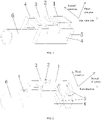
- FIG. 1 is a schematic structural diagram 1 of an in-vivo detection apparatus based on a flexible tube according to an embodiment of the present invention.
- FIG. 2 is a schematic structural diagram 2 of an in-vivo detection apparatus based on a flexible tube according to an embodiment of the present invention.
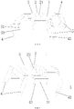
- FIG. 3 is a schematic structural diagram 3 of an in-vivo detection apparatus based on a flexible tube according to an embodiment of the present invention.
- FIG. 4 is a schematic structural diagram 4 of an in-vivo detection apparatus based on a flexible tube according to an embodiment of the present invention.
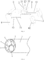
- FIG. 5 is a schematic structural diagram 5 of an in-vivo detection apparatus based on a flexible tube according to an embodiment of the present invention.
- FIG. 6 is a schematic structural diagram 6 of an in-vivo detection apparatus based on a flexible tube according to an embodiment of the present invention.
- the in-vivo detection apparatus based on the flexible tube includes: a detection component 1, a main circuit board 3, a detection circuit board 2, auxiliary circuit boards 4, a cable, and an outer tube 7.
- the main circuit board 3 is provided with two first edges parallel to each other disposed along a first direction, and a second edge disposed along a second direction. It may be understood that the first edge is used to connect to an edge of the detection circuit board 2. It may be understood that the second edge is used to connect to an edge of the auxiliary circuit board 4.
- a first conducting material 21 is disposed on a first side surface of the detection circuit board 2, the detection component 1 is connected to the first side surface of the detection circuit board 2, and a wiring terminal of the detection component 1 is welded to the first conducting material 21.
- a second conducting material 22 is disposed on a second side surface of the detection circuit board 2, the second side surface of the detection circuit board 2 is connected to the second edge of the main circuit board 3, the second conducting material 22 is perpendicularly welded to a conductive portion on a surface of the main circuit board 3, and the conductive portion is conductively connected to the cable. The first conducting material is conducted to the second conducting material.
- the first conducting material 21 may be any material that can be connected and electrically conductive, and may be a metal sheet such as a copper sheet. In an implementation, the first conducting material may be disposed on the first side surface. In another optional implementation, the first conducting material 21 may also be disposed in an opening groove of the first side surface.
- the second conducting material 22 can be any material that can be connected and electrically conductive, and may be a metal sheet such as a copper sheet. In an implementation, the second conducting material may be disposed on the second side surface. In another optional implementation, the second conducting material 22 may also be disposed in an opening groove of the second side surface.
- the conduction and connection manner may be any manner in which two side surfaces of a circuit board are conducted and connected.
- the conductive portion may include a line for power supply and may further include a line for signal transmission.
- the conductive portion may include any conductive material, circuit, or the like, and may have a first connecting surface.
- the first connecting surface may be directly welded and connected to the second conducting material 22.
- the conductive portion may further have a second connecting surface.
- the first connecting surface and the second connecting surface may be integrated, and can conduct and transmit electrical signals.
- the second connecting surface can be welded and connected to a cable of a signal line, and a connection manner may be welding.
- the conductive portion may be any material that can be connected and electrically conductive, for example, a metal sheet such as a copper sheet. The metal sheet can be bent to form the first connecting surface and the second connecting surface.
- the conductive portion may be further conductively connected to the cable, the cable may be the signal line, or a part of the signal line for connection.
- a grounding portion may be further disposed on the main circuit board 3, and may also be conductively connected to a ground cable.
- a conductive material of the detection circuit board 2 may be disposed to enlarge a welding spot of the detection component 1.
- the detection circuit board 2 is welded to the main circuit board 3, and the main circuit board 3 facilitates welding of the signal line, the conductive portion, and the like, and increases welding strength.
- the first conducting material is welded to the wiring terminal of the detection component, and the first conducting material may form the connecting surface, thereby preventing a cable of the detection component from being welded to the cable. Because the wiring terminal needs to be welded only to the first conducting material on the first side surface, difficulty of welding operations is reduced, welding strength and reliability are enhanced, and welding stability in a plurality of motion statuses is satisfied.
- the detection component 1 may be further connected to at least one of the detection circuit board 2 and the auxiliary circuit board 4 in any other manner.
- another surface of the detection component 1 may be welded to at least one of the detection circuit board 2 and the auxiliary circuit board 4.
- a distance between the auxiliary circuit boards 4 may also be suitable for clamping the detection component 1 to locate positions of the auxiliary circuit boards.
- the distance may be less than or equal to a maximum size of the detection component 1 along the second direction.
- each of the auxiliary circuit boards 4 is connected to one of the first edges, a channel for at least a part of the instrument tube 6 to pass through is formed between the two auxiliary circuit boards 4, and the channel is provided on a side, along a first direction, of the detection component 1, the main circuit board 3, and the detection circuit board 2.
- the instrument tube 6 can be understood as a tube that can be equipped with a biopsy instrument, a laser instrument, or the like, and may be flexible. For details, refer to definitions of the instrument tube 6 in the controllable curved tube in the field for understanding.
- the first direction, the second direction, and the third direction are perpendicular to each other. Specifically, all the main circuit board 3, the detection circuit board 2, and the auxiliary circuit board 4 are perpendicular to each other.
- the detection component 1 Stable mounting and use of the detection component 1 are ensured by using the main circuit board 3, the detection circuit board 2, and the auxiliary circuit board 4, so that the detection component 1 is not impacted by external force.
- the side surface of the auxiliary circuit board 4 is connected to the first edge of the main circuit board 3
- the side surface of the detection circuit board 2 is connected to the second edge of the main circuit board 3
- the channel is formed to provide a cavity structure whose shape is similar to H, thereby avoiding an excessively large size in any direction, and helping reduce an overall size of the apparatus by rationalizing space utilization.
- a surface size of the second conducting material 22 is greater than a surface size of the first conducting material 21. Therefore, because a surface size of the second conducting material 22 is greater than a surface size of the first conducting material 21, after the main circuit board 3 is perpendicularly welded to the second conducting material 22 of the detection circuit board 2, a connection between the detection component 1 and the cable may be changed from a point to a line, thereby effectively enhancing welding strength and reliability, and satisfying welding stability in a plurality of motion statuses.
- the detection component 1 may be an image acquisition component. In another optional implementation, the detection component 1 may also be any detection apparatus that detects physical and chemical properties of a liquid, a gas, or a solid, such as a liquid detection component or a gas detection component.
- the detection component 1 may be the image acquisition component. With quick development of image sensors, the smallest image sensor can now achieve 0.7 ⁇ 0.7 mm. Therefore, there is an urgent need for a packaging structure that can effectively control an external diameter and be safely and reliably packaged with lighting and low costs. However, the apparatus in this embodiment can exactly meet this demand.
- the apparatus further includes a lighting component 5, where the lighting component 5 is disposed at an end of the auxiliary circuit board 4, and the lighting component 5 and the detection component 1 face a same direction. That is, the lighting component 5 is configured to shine to a direction in which the image acquisition component performs acquisition. Because the lighting component 5 is disposed at an end of the auxiliary circuit board 4, the lighting components may be symmetrically disposed on two sides of the detection component 1, so as to help implement clear lighting.
- the lighting component 5 may be any component that can emit light, and may be any component with any color or any lighting principle.
- the lighting component 5 may be an LED.
- the lighting component 5 may be monochromatic, multicolor, or allochroic.
- this embodiment is designed ingeniously, makes rational utilization of space, and is simple, reliable, and easy to manufacture.
- this embodiment may also be manufactured using common standard parts with low costs. Therefore, based on this embodiment, a radial packaging size of the detection component and the lighting component can be effectively controlled.
- an overall apparatus with a diameter of less than 3 mm can be obtained through packaging, thereby greatly expanding an application scope of the detection component of, for example, a micro sensor in this field.
- a lighting conducting material 41 is disposed on each of opposite side surfaces of the two auxiliary circuit boards 4, the lighting conducting material 41 is welded to a wiring terminal of the lighting component 5, and the two lighting components are connected in parallel by using the two lighting conducting materials.
- the wiring terminal may include a cable for power supply, a signal line for control, or the like.
- the lighting conducting material 41 may be welded to another conductive portion on a surface of the main circuit board 3, and the two lighting components 5 are connected in parallel.
- the conductive portion can be understood with reference to the conductive portion connecting the second conducting material and the cable.
- the two conductive portions may be interconnected or independent of each other.
- the lighting conducting material 41 may also be directly welded to the cable, and the two lighting components 5 are connected in parallel.
- mounting of the lighting component 5 and electrical transmission may be further implemented by using the auxiliary circuit board 4 and the lighting conducting material 41 on the auxiliary circuit board 4.
- stability of electrical transmission of the lighting component 5 may be further ensured, and size simplification is facilitated.
- the lighting component 5 may be further connected to at least one of the detection circuit board 2 and the main circuit board 3 in any other manner.
- the lighting conducting material 41 is welded to the corresponding cable and line
- another surface of the lighting component 5 may be further welded to at least one of the detection circuit board 2 and the main circuit board 3, to further ensure a connection effect.
- a bayonet is provided along the first direction at an end of the auxiliary circuit board 4, and the lighting component 5 is disposed at the bayonet.
- the bayonet may be specifically a second bayonet 42 shown in FIG. 3, FIG. 4 , and FIG. 5 .
- a connection between the bayonet and the lighting component 5 may be performed by matching a size of the bayonet and a size of the lighting component 5.
- the matching may mean that sizes of the bayonet and the lighting component are the same along the third direction, or that the size of the bayonet along the third direction is less than the size of the lighting component 5 along the third direction.
- another auxiliary connection structure may be further disposed.
- the second bayonet 42 may be C-shaped, to surround three side surfaces of the lighting component 5, to implement two-sided clamping on the lighting component 5.
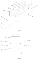
- FIG. 7 is a schematic structural diagram 1 of an in-vivo detection apparatus based on a flexible tube according to another embodiment of the present invention.
- FIG. 8 is a schematic structural diagram 2 of an in-vivo detection apparatus based on a flexible tube according to another embodiment of the present invention.
- the second bayonet 42 may be L-shaped, to surround two side surfaces of the lighting component 5, to implement single-sided clamping on the lighting component 5.
- the second bayonet 42 may facilitate mounting of the lighting component 5, especially facilitate mounting with a tolerance, and may also adapt to lighting components 5 of different sizes and models.
- a distance between the lighting component 5 and the first side surface of the detection circuit board 2 along the first direction matches a length of the detection component 1 along the first direction. Therefore, it may be understood that the matching is performed, so that an end, distal from the detection circuit board 2, of the detection component 1 and an end, distal from the detection circuit board 2, of the lighting component 5 stay in a same reference plane, and the reference plane is a plane perpendicular to the first direction.
- the end of the lighting component 5 may also be slightly higher or lower than the end of the detection component 2 along the first direction. The two ends conform to the matching described above, and are also located in a same reference plane described above.
- the lighting component 5 and the detection component 2 being in the same reference plane can make lighting more uniform.
- the detection circuit board 2 and the main circuit board 3, and/or the auxiliary circuit board 4 and the main circuit board 3 are separately located and connected by using a locating bayonet structure.
- the locating bayonet structure of the detection circuit board 2 and the main circuit board 3 can be understood as including a first bayonet 32 located on the second edge of the main circuit board 3 and a first extension portion 23 extending on two sides of the detection circuit board 2 along the second direction. Therefore, a size of the first bayonet 32 matches the detection circuit board 2, so that when the detection circuit board 2 is embedded into the first bayonet 32, the first extension portion 23 may be erected on the main circuit board 3. In another optional implementation, referring to FIG. 7 and FIG. 8 , the detection circuit board 2 may not have the first extension portion 23.
- a support portion 8 is disposed on the detection circuit board 2 along the third direction on a side proximal to the channel.
- the support portion 8 may be connected to the detection circuit board 2.
- the detection circuit board 2 and the support portion may be integrated, or may be assembled together.
- Two sides of the support portion 8 along the second direction may be respectively connected to the two auxiliary circuit boards 4.
- a side, proximal to the channel, of the support portion 8 along the third direction may be an arc groove that matches an outer diameter of the instrument tube 6.
- the matching may mean that the arc groove is suitable for the instrument tube 6 to pass through.
- radiuses of curvature of the arc groove and the instrument tube may be the same or different.
- the support portion 8 may provide support between the two auxiliary circuit boards 4.
- a locating bayonet structure of the auxiliary circuit board 4 and the main circuit board 3 may be understood as including a second extension portion 31 extending on two sides of the main circuit board 3 along the second direction, and a third bayonet 43 provided on an edge of the auxiliary circuit board 4 along the third direction.
- the second extension portion 31 may be embedded into the third bayonet 43 corresponding to the auxiliary circuit board 4, so that the main circuit board 3 can be erected on the two auxiliary circuit boards 4.
- a third extension portion 33 further extends along the first direction, and the third extension portion 33 may be disposed on two sides of the detection component 1 along the second direction.
- a size of the third bayonet 43 may match a size of the second extension portion 31 and a size of the third extension portion 33, which may be understood as that the size of the third bayonet 43 along the first direction may be the same as or close to a sum of the size of the second extension portion 31 and the size of the third extension portion 33 along the first direction.
- the third extension portion 33 may help ensure stability of the structure.
- Locating and a connection between circuit boards may be implemented based on the foregoing designs.
- the cable conductively connected to the conductive portion is a coaxial cable with a shielding layer.
- the shielding layer can effectively increase welding strength and avoid occurrence of an abnormality in the cable.
- the detection component 1, the main circuit board 3, the detection circuit board 2, the auxiliary circuit board 4, and a part of the instrument tube 6 disposed in the channel are all disposed in the outer tube 7.
- the outer tube 7 can be filled with glue, through which locations of the circuit boards, components, and instrument tubes can be fixed, thereby implementing overall packaging of the apparatus.
- the outer tube 7 being filled with glue means that as long as there is glue in the outer tube 7, the above description applies regardless of whether all empty spaces are filled.
- the description of this embodiment also applies.
- This embodiment further provides an in-vivo detection system based on a flexible tube, including the in-vivo detection apparatus based on the flexible tube, the flexible controllable curved tube, and the instrument tube in the foregoing embodiments and the optional manners of the foregoing embodiments, where the in-vivo detection apparatus and the instrument tube form an insertion portion at an end of the controllable curved tube.
- the insertion portion and the controllable curved tube may be a controllable curved tube and an insertion portion of an endoscope.
- the first conducting material is disposed on the first side surface of the detection circuit board, and when the detection component is connected to the first side surface of the detection circuit board, the wiring terminal of the detection component is welded to the first conducting material, so that the wiring terminal of the detection component can be prevented from being welded to the cable. Because the wiring terminal needs to be welded only to the first conducting material on the first side surface, difficulty of welding operations is reduced, welding strength and reliability are enhanced, and welding stability in a plurality of motion statuses is satisfied.
- the main circuit board, the detection circuit board, and the auxiliary circuit board are further ensured by using the main circuit board, the detection circuit board, and the auxiliary circuit board, so that the detection component is not impacted by external force.
- the side surface of the auxiliary circuit board is connected to the first edge of the main circuit board
- the side surface of the detection circuit board is connected to the second edge of the main circuit board
- the channel is formed to provide a cavity structure whose shape is similar to H, thereby helping reduce an overall size of the apparatus by rationalizing space utilization.
- a connection between the detection component and the cable may be changed from a point to a line, thereby effectively enhancing welding strength and reliability, and satisfying welding stability in a plurality of motion statuses.
- mounting of the lighting component and electrical transmission may be further implemented by using the auxiliary circuit board and the lighting conducting material on the auxiliary circuit board.
- stability of electrical transmission of the lighting component may be further ensured, and size simplification is facilitated.
- a distance between the lighting component and the first side surface of the detection circuit board along the first direction matches a length of the detection component along the first direction, so that an end of the lighting component stays in a same plane as an end of the detection component, thereby ensuring lighting uniformity.
Landscapes
- Health & Medical Sciences (AREA)
- Life Sciences & Earth Sciences (AREA)
- Surgery (AREA)
- Engineering & Computer Science (AREA)
- Biomedical Technology (AREA)
- Molecular Biology (AREA)
- Pathology (AREA)
- Radiology & Medical Imaging (AREA)
- Nuclear Medicine, Radiotherapy & Molecular Imaging (AREA)
- Biophysics (AREA)
- Physics & Mathematics (AREA)
- Heart & Thoracic Surgery (AREA)
- Medical Informatics (AREA)
- Optics & Photonics (AREA)
- Animal Behavior & Ethology (AREA)
- General Health & Medical Sciences (AREA)
- Public Health (AREA)
- Veterinary Medicine (AREA)
- Manufacturing & Machinery (AREA)
- Endoscopes (AREA)
- Instruments For Viewing The Inside Of Hollow Bodies (AREA)
- Geophysics And Detection Of Objects (AREA)
Description
- The present invention relates to the medical field, and in particular, to an in-vivo detection apparatus and system based on a flexible tube.
- With development of science and technologies, in-vivo detection technologies based on flexible tubes have been widely applied to the medical field. An in-vivo detection apparatus based on a flexible tube can be extended into a human body to help medical personnel inspect an internal organ of the human body.
- In the related art, the in-vivo detection apparatus based on the flexible tube may include a flexible controllable curved tube and a detection component disposed at an end of the controllable curved tube. A wiring terminal of the detection component may be welded to another cable through welding, so as to implement electrical transmission.
- International Publication number,
WO2015/002847A2 disclosed an electronic circuit board assembly for a tip section of a multiple viewing elements endoscope, head 3930 of endoscope 3900 comprises at least a forward looking camera 39116 and two side looking cameras 3920a and 3920b. Each of cameras 39116 and 3920a, 3920b is provided with an optical imaging system such as lens assemblies (systems) 39132 and 3932 respectively and solid state detector arrays 39134 and 3934 respectively. Front camera elements 3936 and 3956 of cameras 39116 and 3920 respectively may be a flat protective window, but optionally an optical element used as part of the imaging systems such as solid state detector arrays 39134 and 3934 respectively. The electrical cable has a diameter ranging from 2 to 2.5 millimeters. - However, due to a relatively small size of the detection component and a relatively small size of a cable of the detection component, it is inconvenient to weld the detection component to another cable. In addition, it is difficult to ensure a welding effect during motion. For example, it is easy for the cable of the detection component to disconnect from another cable during motion.
- The present invention provides an in-vivo detection apparatus and system based on a flexible tube, to resolve problems that the detection component is inconvenient to operate during welding when a packaging size is limited, and it is difficult to ensure a welding effect during motion.
- According to a first aspect of the present invention, an in-vivo detection apparatus as defined in
independent claim 1 is provided. - Optionally, the detection component is an image acquisition component.
- Optionally, the apparatus further includes two lighting components, where each of the two lighting components is disposed at an end of each of the two auxiliary circuit boards, and the two lighting components and the detection component face a same direction.
- Optionally, a lighting conducting material is disposed on each of opposite side surfaces of the two auxiliary circuit boards, the lighting conducting material is welded to a wiring terminal of each of the two lighting components, and the two lighting components are connected in parallel by using two lighting conducting materials.
- Optionally, a bayonet is provided along the first direction at an end of each of the two auxiliary circuit boards, and each of the two lighting components is disposed at the bayonet.
- Optionally, a distance between each of the two lighting components and the first side surface of the detection circuit board along the first direction matches a length of the detection component along the first direction.
- Optionally, a surface size of the second conducting material is greater than a surface size of the first conducting material.
- Optionally, the detection circuit board and the main circuit board, and/or each of the two auxiliary circuit boards and the main circuit board are separately located and connected by using a locating bayonet structure.
- Optionally, the cable conductively connected to the conductive portion is a coaxial cable with a shielding layer.
- Optionally, the outer tube is filled with glue.
- According to a second aspect of the present invention, an in-vivo detection system is provided, including the in-vivo detection apparatus according to the first aspect and the optional solutions of the first aspect, and an instrument tube, where the in-vivo detection apparatus and the instrument tube form an insertion portion at an end of the controllable curved tube.
- For the in-vivo detection apparatus and system based on the flexible tube provided in the present invention, the first conducting material is disposed on the first side surface of the detection circuit board, and when the detection component is connected to the first side surface of the detection circuit board, the wiring terminal of the detection component is welded to the first conducting material, so that the wiring terminal of the detection component can be prevented from being welded to the cable. Because the wiring terminal needs to be welded only to the first conducting material on the first side surface, difficulty of welding operations is reduced, welding strength and reliability are enhanced, and welding stability in a plurality of motion statuses is satisfied.
- Based on the present invention, stable mounting and use of the detection component are further ensured by using the main circuit board, the detection circuit board, and the auxiliary circuit board, so that the detection component is not impacted by external force. In addition, the side surface of the auxiliary circuit board is connected to the first edge of the main circuit board, the side surface of the detection circuit board is connected to the second edge of the main circuit board, and the channel is formed to provide a cavity structure whose shape is similar to H, thereby helping reduce an overall size of the apparatus by rationalizing space utilization.
- In an optional solution of the present invention, because a surface size of the second conducting material is greater than a surface size of the first conducting material, after the main circuit board is perpendicularly welded to the second conducting material of the detection circuit board, a connection between the detection component and the cable may be changed from a point to a line, thereby effectively enhancing welding strength and reliability, and satisfying welding stability in a plurality of motion statuses.
- In an optional solution of the present invention, mounting of the lighting component and electrical transmission may be further implemented by using the auxiliary circuit board and the lighting conducting material on the auxiliary circuit board. In addition, stability of electrical transmission of the lighting component may be further ensured, and size simplification is facilitated.
- In an optional solution of the present invention, a distance between the lighting component and the first side surface of the detection circuit board along the first direction matches a length of the detection component along the first direction, so that an end of the lighting component stays in a same plane as an end of the detection component, thereby ensuring lighting uniformity.
- To describe the technical solutions in the embodiments of the present invention or in the prior art more clearly, accompanying drawings required to describe the embodiments or the prior art are briefly described below. It is obvious that the accompanying drawings described below are only some embodiments of the present invention. It is apparent to those of ordinary skill in the art that other drawings may be further obtained based on the accompanying drawings without inventive effort.
-
FIG. 1 is a schematic structural diagram 1 of an in-vivo detection apparatus based on a flexible tube according to an embodiment of the present invention; -
FIG. 2 is a schematic structural diagram 2 of an in-vivo detection apparatus based on a flexible tube according to an embodiment of the present invention; -
FIG. 3 is a schematic structural diagram 3 of an in-vivo detection apparatus based on a flexible tube according to an embodiment of the present invention; -
FIG. 4 is a schematic structural diagram 4 of an in-vivo detection apparatus based on a flexible tube according to an embodiment of the present invention; -
FIG. 5 is a schematic structural diagram 5 of an in-vivo detection apparatus based on a flexible tube according to an embodiment of the present invention; -
FIG. 6 is a schematic structural diagram 6 of an in-vivo detection apparatus based on a flexible tube according to an embodiment of the present invention; -
FIG. 7 is a schematic structural diagram 1 of an in-vivo detection apparatus based on a flexible tube according to another embodiment of the present invention; and -
FIG. 8 is a schematic structural diagram 2 of an in-vivo detection apparatus based on a flexible tube according to another embodiment of the present invention, where - 1-detection component;
- 2-detection circuit board;
- 21-first conducting material;
- 22-second conducting material;
- 23-first extension portion;
- 3-main circuit board;
- 31-second extension portion;
- 32-first bayonet;
- 33-third extension portion;
- 4-auxiliary circuit board;
- 41-lighting conducting material;
- 42-second bayonet;
- 43-third bayonet;
- 5-lighting component; and
- 6-instrument tube;
- 7-outer tube; and
- 8-support structure.
- The technical solutions of the present invention are described in detail below with reference to the specific embodiments.
-
FIG. 1 is a schematic structural diagram 1 of an in-vivo detection apparatus based on a flexible tube according to an embodiment of the present invention.FIG. 2 is a schematic structural diagram 2 of an in-vivo detection apparatus based on a flexible tube according to an embodiment of the present invention.FIG. 3 is a schematic structural diagram 3 of an in-vivo detection apparatus based on a flexible tube according to an embodiment of the present invention.FIG. 4 is a schematic structural diagram 4 of an in-vivo detection apparatus based on a flexible tube according to an embodiment of the present invention.FIG. 5 is a schematic structural diagram 5 of an in-vivo detection apparatus based on a flexible tube according to an embodiment of the present invention.FIG. 6 is a schematic structural diagram 6 of an in-vivo detection apparatus based on a flexible tube according to an embodiment of the present invention. - Referring to
FIG. 1 to FIG. 6 , the in-vivo detection apparatus based on the flexible tube includes: adetection component 1, amain circuit board 3, adetection circuit board 2,auxiliary circuit boards 4, a cable, and anouter tube 7. - The
main circuit board 3 is provided with two first edges parallel to each other disposed along a first direction, and a second edge disposed along a second direction. It may be understood that the first edge is used to connect to an edge of thedetection circuit board 2. It may be understood that the second edge is used to connect to an edge of theauxiliary circuit board 4. - A
first conducting material 21 is disposed on a first side surface of thedetection circuit board 2, thedetection component 1 is connected to the first side surface of thedetection circuit board 2, and a wiring terminal of thedetection component 1 is welded to the first conductingmaterial 21. Asecond conducting material 22 is disposed on a second side surface of thedetection circuit board 2, the second side surface of thedetection circuit board 2 is connected to the second edge of themain circuit board 3, thesecond conducting material 22 is perpendicularly welded to a conductive portion on a surface of themain circuit board 3, and the conductive portion is conductively connected to the cable. The first conducting material is conducted to the second conducting material. - The
first conducting material 21 may be any material that can be connected and electrically conductive, and may be a metal sheet such as a copper sheet. In an implementation, the first conducting material may be disposed on the first side surface. In another optional implementation, the first conductingmaterial 21 may also be disposed in an opening groove of the first side surface. - The
second conducting material 22 can be any material that can be connected and electrically conductive, and may be a metal sheet such as a copper sheet. In an implementation, the second conducting material may be disposed on the second side surface. In another optional implementation, thesecond conducting material 22 may also be disposed in an opening groove of the second side surface. - In addition, the first conducting
material 21 is conductively connected to thesecond conducting material 22. The conduction and connection manner may be any manner in which two side surfaces of a circuit board are conducted and connected. - The conductive portion may include a line for power supply and may further include a line for signal transmission. Specifically, the conductive portion may include any conductive material, circuit, or the like, and may have a first connecting surface. The first connecting surface may be directly welded and connected to the
second conducting material 22. The conductive portion may further have a second connecting surface. The first connecting surface and the second connecting surface may be integrated, and can conduct and transmit electrical signals. The second connecting surface can be welded and connected to a cable of a signal line, and a connection manner may be welding. The conductive portion may be any material that can be connected and electrically conductive, for example, a metal sheet such as a copper sheet. The metal sheet can be bent to form the first connecting surface and the second connecting surface. The conductive portion may be further conductively connected to the cable, the cable may be the signal line, or a part of the signal line for connection. In addition, a grounding portion may be further disposed on themain circuit board 3, and may also be conductively connected to a ground cable. - It may be seen that a conductive material of the
detection circuit board 2 may be disposed to enlarge a welding spot of thedetection component 1. Thedetection circuit board 2 is welded to themain circuit board 3, and themain circuit board 3 facilitates welding of the signal line, the conductive portion, and the like, and increases welding strength. - The first conducting material is welded to the wiring terminal of the detection component, and the first conducting material may form the connecting surface, thereby preventing a cable of the detection component from being welded to the cable. Because the wiring terminal needs to be welded only to the first conducting material on the first side surface, difficulty of welding operations is reduced, welding strength and reliability are enhanced, and welding stability in a plurality of motion statuses is satisfied.
- In addition, the
detection component 1 may be further connected to at least one of thedetection circuit board 2 and theauxiliary circuit board 4 in any other manner. For example, in addition to welding of the first conductingmaterial 21 and the cable, another surface of thedetection component 1 may be welded to at least one of thedetection circuit board 2 and theauxiliary circuit board 4. - In another optional implementation, a distance between the
auxiliary circuit boards 4 may also be suitable for clamping thedetection component 1 to locate positions of the auxiliary circuit boards. For example, the distance may be less than or equal to a maximum size of thedetection component 1 along the second direction. - In this embodiment, each of the
auxiliary circuit boards 4 is connected to one of the first edges, a channel for at least a part of theinstrument tube 6 to pass through is formed between the twoauxiliary circuit boards 4, and the channel is provided on a side, along a first direction, of thedetection component 1, themain circuit board 3, and thedetection circuit board 2. - The
instrument tube 6 can be understood as a tube that can be equipped with a biopsy instrument, a laser instrument, or the like, and may be flexible. For details, refer to definitions of theinstrument tube 6 in the controllable curved tube in the field for understanding. - The first direction, the second direction, and the third direction are perpendicular to each other. Specifically, all the
main circuit board 3, thedetection circuit board 2, and theauxiliary circuit board 4 are perpendicular to each other. - Stable mounting and use of the
detection component 1 are ensured by using themain circuit board 3, thedetection circuit board 2, and theauxiliary circuit board 4, so that thedetection component 1 is not impacted by external force. In addition, the side surface of theauxiliary circuit board 4 is connected to the first edge of themain circuit board 3, the side surface of thedetection circuit board 2 is connected to the second edge of themain circuit board 3, and the channel is formed to provide a cavity structure whose shape is similar to H, thereby avoiding an excessively large size in any direction, and helping reduce an overall size of the apparatus by rationalizing space utilization. - In an implementation, a surface size of the
second conducting material 22 is greater than a surface size of the first conductingmaterial 21. Therefore, because a surface size of thesecond conducting material 22 is greater than a surface size of the first conductingmaterial 21, after themain circuit board 3 is perpendicularly welded to thesecond conducting material 22 of thedetection circuit board 2, a connection between thedetection component 1 and the cable may be changed from a point to a line, thereby effectively enhancing welding strength and reliability, and satisfying welding stability in a plurality of motion statuses. - In an implementation, the
detection component 1 may be an image acquisition component. In another optional implementation, thedetection component 1 may also be any detection apparatus that detects physical and chemical properties of a liquid, a gas, or a solid, such as a liquid detection component or a gas detection component. - The
detection component 1 may be the image acquisition component. With quick development of image sensors, the smallest image sensor can now achieve 0.7∗0.7 mm. Therefore, there is an urgent need for a packaging structure that can effectively control an external diameter and be safely and reliably packaged with lighting and low costs. However, the apparatus in this embodiment can exactly meet this demand. - To be suitable for implementing effective image acquisition, the apparatus further includes a
lighting component 5, where thelighting component 5 is disposed at an end of theauxiliary circuit board 4, and thelighting component 5 and thedetection component 1 face a same direction. That is, thelighting component 5 is configured to shine to a direction in which the image acquisition component performs acquisition. Because thelighting component 5 is disposed at an end of theauxiliary circuit board 4, the lighting components may be symmetrically disposed on two sides of thedetection component 1, so as to help implement clear lighting. - The
lighting component 5 may be any component that can emit light, and may be any component with any color or any lighting principle. For example, thelighting component 5 may be an LED. In a specific implementation process, thelighting component 5 may be monochromatic, multicolor, or allochroic. - It may be seen that this embodiment is designed ingeniously, makes rational utilization of space, and is simple, reliable, and easy to manufacture. In addition, this embodiment may also be manufactured using common standard parts with low costs. Therefore, based on this embodiment, a radial packaging size of the detection component and the lighting component can be effectively controlled. In a specific implementation process, an overall apparatus with a diameter of less than 3 mm can be obtained through packaging, thereby greatly expanding an application scope of the detection component of, for example, a micro sensor in this field.
- In a specific implementation process, referring to
FIG. 5 , alighting conducting material 41 is disposed on each of opposite side surfaces of the twoauxiliary circuit boards 4, thelighting conducting material 41 is welded to a wiring terminal of thelighting component 5, and the two lighting components are connected in parallel by using the two lighting conducting materials. The wiring terminal may include a cable for power supply, a signal line for control, or the like. In an example, thelighting conducting material 41 may be welded to another conductive portion on a surface of themain circuit board 3, and the twolighting components 5 are connected in parallel. The conductive portion can be understood with reference to the conductive portion connecting the second conducting material and the cable. In addition, the two conductive portions may be interconnected or independent of each other. In another example, thelighting conducting material 41 may also be directly welded to the cable, and the twolighting components 5 are connected in parallel. - It may be seen that, in this implementation, mounting of the
lighting component 5 and electrical transmission may be further implemented by using theauxiliary circuit board 4 and thelighting conducting material 41 on theauxiliary circuit board 4. In addition, stability of electrical transmission of thelighting component 5 may be further ensured, and size simplification is facilitated. - In addition, the
lighting component 5 may be further connected to at least one of thedetection circuit board 2 and themain circuit board 3 in any other manner. For example, in addition to that thelighting conducting material 41 is welded to the corresponding cable and line, another surface of thelighting component 5 may be further welded to at least one of thedetection circuit board 2 and themain circuit board 3, to further ensure a connection effect. - In an implementation, a bayonet is provided along the first direction at an end of the
auxiliary circuit board 4, and thelighting component 5 is disposed at the bayonet. The bayonet may be specifically asecond bayonet 42 shown inFIG. 3, FIG. 4 , andFIG. 5 . - A connection between the bayonet and the
lighting component 5 may be performed by matching a size of the bayonet and a size of thelighting component 5. The matching may mean that sizes of the bayonet and the lighting component are the same along the third direction, or that the size of the bayonet along the third direction is less than the size of thelighting component 5 along the third direction. In addition, another auxiliary connection structure may be further disposed. - In the embodiments shown in
FIG. 1 to FIG. 6 , thesecond bayonet 42 may be C-shaped, to surround three side surfaces of thelighting component 5, to implement two-sided clamping on thelighting component 5. -
FIG. 7 is a schematic structural diagram 1 of an in-vivo detection apparatus based on a flexible tube according to another embodiment of the present invention.FIG. 8 is a schematic structural diagram 2 of an in-vivo detection apparatus based on a flexible tube according to another embodiment of the present invention. - In the embodiments shown in
FIG. 7 and FIG. 8 , thesecond bayonet 42 may be L-shaped, to surround two side surfaces of thelighting component 5, to implement single-sided clamping on thelighting component 5. Thesecond bayonet 42 may facilitate mounting of thelighting component 5, especially facilitate mounting with a tolerance, and may also adapt tolighting components 5 of different sizes and models. - In an implementation, referring to
FIG. 1 to FIG. 3 , a distance between thelighting component 5 and the first side surface of thedetection circuit board 2 along the first direction matches a length of thedetection component 1 along the first direction. Therefore, it may be understood that the matching is performed, so that an end, distal from thedetection circuit board 2, of thedetection component 1 and an end, distal from thedetection circuit board 2, of thelighting component 5 stay in a same reference plane, and the reference plane is a plane perpendicular to the first direction. In addition, the end of thelighting component 5 may also be slightly higher or lower than the end of thedetection component 2 along the first direction. The two ends conform to the matching described above, and are also located in a same reference plane described above. - In the foregoing implementation, the
lighting component 5 and thedetection component 2 being in the same reference plane can make lighting more uniform. - In an implementation, the
detection circuit board 2 and themain circuit board 3, and/or theauxiliary circuit board 4 and themain circuit board 3 are separately located and connected by using a locating bayonet structure. - Referring to
FIG. 5 , the locating bayonet structure of thedetection circuit board 2 and themain circuit board 3 can be understood as including afirst bayonet 32 located on the second edge of themain circuit board 3 and afirst extension portion 23 extending on two sides of thedetection circuit board 2 along the second direction. Therefore, a size of thefirst bayonet 32 matches thedetection circuit board 2, so that when thedetection circuit board 2 is embedded into thefirst bayonet 32, thefirst extension portion 23 may be erected on themain circuit board 3. In another optional implementation, referring toFIG. 7 and FIG. 8 , thedetection circuit board 2 may not have thefirst extension portion 23. - In a specific implementation, referring to
FIG. 8 , asupport portion 8 is disposed on thedetection circuit board 2 along the third direction on a side proximal to the channel. Thesupport portion 8 may be connected to thedetection circuit board 2. Thedetection circuit board 2 and the support portion may be integrated, or may be assembled together. Two sides of thesupport portion 8 along the second direction may be respectively connected to the twoauxiliary circuit boards 4. In addition, a side, proximal to the channel, of thesupport portion 8 along the third direction may be an arc groove that matches an outer diameter of theinstrument tube 6. The matching may mean that the arc groove is suitable for theinstrument tube 6 to pass through. In addition, radiuses of curvature of the arc groove and the instrument tube may be the same or different. Thesupport portion 8 may provide support between the twoauxiliary circuit boards 4. - Referring to
FIG. 3 to FIG. 5 , a locating bayonet structure of theauxiliary circuit board 4 and themain circuit board 3 may be understood as including asecond extension portion 31 extending on two sides of themain circuit board 3 along the second direction, and athird bayonet 43 provided on an edge of theauxiliary circuit board 4 along the third direction. Thesecond extension portion 31 may be embedded into thethird bayonet 43 corresponding to theauxiliary circuit board 4, so that themain circuit board 3 can be erected on the twoauxiliary circuit boards 4. - In an implementation, referring to
FIG.7 , for thesecond extension portion 31, athird extension portion 33 further extends along the first direction, and thethird extension portion 33 may be disposed on two sides of thedetection component 1 along the second direction. Correspondingly, a size of thethird bayonet 43 may match a size of thesecond extension portion 31 and a size of thethird extension portion 33, which may be understood as that the size of thethird bayonet 43 along the first direction may be the same as or close to a sum of the size of thesecond extension portion 31 and the size of thethird extension portion 33 along the first direction. Thethird extension portion 33 may help ensure stability of the structure. - Locating and a connection between circuit boards may be implemented based on the foregoing designs.
- In an implementation, the cable conductively connected to the conductive portion is a coaxial cable with a shielding layer. The shielding layer can effectively increase welding strength and avoid occurrence of an abnormality in the cable.
- Referring to
FIG. 6 , thedetection component 1, themain circuit board 3, thedetection circuit board 2, theauxiliary circuit board 4, and a part of theinstrument tube 6 disposed in the channel are all disposed in theouter tube 7. Theouter tube 7 can be filled with glue, through which locations of the circuit boards, components, and instrument tubes can be fixed, thereby implementing overall packaging of the apparatus. - It may be understood that, the
outer tube 7 being filled with glue means that as long as there is glue in theouter tube 7, the above description applies regardless of whether all empty spaces are filled. In addition, even if only at least two of thedetection component 1, thelighting component 5, the circuit boards, theinstrument tube 6, and theouter tube 7 are connected by glue, the description of this embodiment also applies. - This embodiment further provides an in-vivo detection system based on a flexible tube, including the in-vivo detection apparatus based on the flexible tube, the flexible controllable curved tube, and the instrument tube in the foregoing embodiments and the optional manners of the foregoing embodiments, where the in-vivo detection apparatus and the instrument tube form an insertion portion at an end of the controllable curved tube.
- The insertion portion and the controllable curved tube may be a controllable curved tube and an insertion portion of an endoscope.
- To sum up, for the in-vivo detection apparatus and system based on the flexible tube provided in this embodiment, the first conducting material is disposed on the first side surface of the detection circuit board, and when the detection component is connected to the first side surface of the detection circuit board, the wiring terminal of the detection component is welded to the first conducting material, so that the wiring terminal of the detection component can be prevented from being welded to the cable. Because the wiring terminal needs to be welded only to the first conducting material on the first side surface, difficulty of welding operations is reduced, welding strength and reliability are enhanced, and welding stability in a plurality of motion statuses is satisfied.
- Based on this embodiment, stable mounting and use of the detection component are further ensured by using the main circuit board, the detection circuit board, and the auxiliary circuit board, so that the detection component is not impacted by external force. In addition, the side surface of the auxiliary circuit board is connected to the first edge of the main circuit board, the side surface of the detection circuit board is connected to the second edge of the main circuit board, and the channel is formed to provide a cavity structure whose shape is similar to H, thereby helping reduce an overall size of the apparatus by rationalizing space utilization.
- In an optional solution of the present invention, because a surface size of the second conducting material is greater than a surface size of the first conducting material, after the main circuit board is perpendicularly welded to the second conducting material of the detection circuit board, a connection between the detection component and the cable may be changed from a point to a line, thereby effectively enhancing welding strength and reliability, and satisfying welding stability in a plurality of motion statuses.
- In an optional solution of this embodiment, mounting of the lighting component and electrical transmission may be further implemented by using the auxiliary circuit board and the lighting conducting material on the auxiliary circuit board. In addition, stability of electrical transmission of the lighting component may be further ensured, and size simplification is facilitated.
- In an optional solution of this embodiment, a distance between the lighting component and the first side surface of the detection circuit board along the first direction matches a length of the detection component along the first direction, so that an end of the lighting component stays in a same plane as an end of the detection component, thereby ensuring lighting uniformity.
Claims (10)
- An in-vivo detection apparatus comprising: a detection component (1), a cable,a main circuit board (3), a detection circuit board (2), two auxiliary circuit boards (4), and an outer tube (7), wherein the main circuit board (3) is provided with two first edges parallel to each other disposed along a first direction, and a second edge disposed along a second direction;wherein a first conducting material (21) is disposed on a first side surface of the detection circuit board (2),wherein the detection component (1) is connected to the first side surface of the detection circuit board (2),wherein a wiring terminal of the detection component (1) is welded to the first conducting material (21);wherein each of the two auxiliary circuit boards (4) is connected to one of the first edges, wherein a channel for at least a part of an instrument tube (6) to pass through is formed between the two auxiliary circuit boards (4), and wherein the channel is provided on a side, along a first direction, of the detection component (1), the main circuit board (3), and the detection circuit board (2),wherein the detection component (1), the main circuit board (3), the detection circuit board (2), the two auxiliary circuit boards (4), and the part of the instrument tube (6) disposed in the channel are all disposed in the outer tube (7); whereinthe outer tube (7) is directly or indirectly connected to a flexible controllable curved tube; andwherein the first direction and the second direction are perpendicular to each other,characterised in thata second conducting material is disposed on a second side surface of the detection circuit board,the second side surface of the detection circuit board is connected to the second edge of the main circuit board,the second conducting material is perpendicularly welded to a conductive portion on a surface of the main circuit board, andthe conductive portion is conductively connected to the cable;the first conducting material is conductively connected to the second conducting material.
- The apparatus according to claim 1, wherein the detection component (1) is an image acquisition component.
- The apparatus according to claim 2, further comprising two lighting components (5), wherein each of the two lighting components (5) is disposed at an end of each of the two auxiliary circuit boards (4), and the two lighting components (5) and the detection component (1) face a same direction.
- The apparatus according to claim 3, wherein a lighting conducting material (41) is disposed on each of opposite side surfaces of the two auxiliary circuit boards (4), wherein
the lighting conducting material (41) is welded to a wiring terminal of each of the two lighting components (5), and wherein the two lighting components (5) are connected in parallel by using two lighting conducting materials (41). - The apparatus according to claim 3, wherein a bayonet is provided along the first direction at an end of each of the two auxiliary circuit boards (4), and wherein each of the two lighting components (5) is disposed at the bayonet.
- The apparatus according to claim 3, wherein a distance between each of the two lighting components (5) and the first side surface of the detection circuit board (2) along the first direction matches a length of the detection component (1) along the first direction.
- The apparatus according to any one of claims 1 to 6, wherein a surface size of the second conducting material (22) is greater than a surface size of the first conducting material (21).
- The apparatus according to any one of claims 1 to 6, wherein the detection circuit board (2) and the main circuit board (3), and/or each of the two auxiliary circuit boards (4) and the main circuit board (3) are separately located and connected by using a locating bayonet structure.
- The apparatus according to any one of claims 1 to 6, wherein the cable conductively connected to the conductive portion is a coaxial cable with a shielding layer.
- An in-vivo detection system comprising the in-vivo detection apparatus according to any of one of claims 1 to 9 and an instrument tube (6), wherein the in-vivo detection apparatus and the instrument tube (6) form an insertion portion at an end of the controllable curved tube.
Applications Claiming Priority (2)
| Application Number | Priority Date | Filing Date | Title |
|---|---|---|---|
| CN201811495228.7A CN109717820B (en) | 2018-12-07 | 2018-12-07 | In-vivo detection device and system based on flexible tube |
| PCT/CN2019/073615 WO2020113808A1 (en) | 2018-12-07 | 2019-01-29 | Flexible catheter-based in vivo detection device and system |
Publications (3)
| Publication Number | Publication Date |
|---|---|
| EP3769664A1 EP3769664A1 (en) | 2021-01-27 |
| EP3769664A4 EP3769664A4 (en) | 2021-07-21 |
| EP3769664B1 true EP3769664B1 (en) | 2022-10-12 |
Family
ID=66295548
Family Applications (1)
| Application Number | Title | Priority Date | Filing Date |
|---|---|---|---|
| EP19893259.2A Active EP3769664B1 (en) | 2018-12-07 | 2019-01-29 | Flexible catheter-based in vivo detection device and system |
Country Status (7)
| Country | Link |
|---|---|
| US (1) | US11903565B2 (en) |
| EP (1) | EP3769664B1 (en) |
| JP (1) | JP7073531B2 (en) |
| CN (1) | CN109717820B (en) |
| ES (1) | ES2929453T3 (en) |
| PT (1) | PT3769664T (en) |
| WO (1) | WO2020113808A1 (en) |
Families Citing this family (4)
| Publication number | Priority date | Publication date | Assignee | Title |
|---|---|---|---|---|
| US12551094B2 (en) | 2021-11-26 | 2026-02-17 | Altek Biotechnology Corporation | Endoscopic image capturing assembly and endoscopic device therewith |
| US11963667B2 (en) | 2021-11-26 | 2024-04-23 | Altek Biotechnology Corporation | Endoscopic image capturing assembly and endoscopic device therewith |
| CN114403782A (en) * | 2022-01-28 | 2022-04-29 | 上海安清医疗器械有限公司 | Endoscope and head end device thereof |
| US12178391B2 (en) * | 2023-02-10 | 2024-12-31 | Evoendo, Inc. | Endoscopy device having an electrical control system |
Family Cites Families (16)
| Publication number | Priority date | Publication date | Assignee | Title |
|---|---|---|---|---|
| JPH089272A (en) * | 1994-04-22 | 1996-01-12 | Olympus Optical Co Ltd | Solid-state image pickup device for electron endoscope |
| JP3284043B2 (en) * | 1996-03-12 | 2002-05-20 | 富士写真光機株式会社 | Tip structure of electronic endoscope |
| KR20080054738A (en) * | 2006-12-13 | 2008-06-19 | (주) 미코티엔 | Probe card |
| JP2011212161A (en) | 2010-03-31 | 2011-10-27 | Fujifilm Corp | Solid-state image pickup device and endoscopic device |
| JP5250653B2 (en) | 2011-03-30 | 2013-07-31 | 富士フイルム株式会社 | Endoscopic imaging apparatus and endoscope |
| JP5503035B2 (en) * | 2012-03-13 | 2014-05-28 | 富士フイルム株式会社 | Endoscope substrate connector and endoscope using the same |
| JP5558600B2 (en) | 2012-03-13 | 2014-07-23 | 富士フイルム株式会社 | Endoscope board connector, endoscope and manufacturing method thereof |
| CN102641124A (en) | 2012-05-04 | 2012-08-22 | 重庆金山科技(集团)有限公司 | Capsule endoscopy |
| CN105636499A (en) | 2013-07-01 | 2016-06-01 | 恩多巧爱思股份有限公司 | Circuit board assembly of a multiple viewing elements endoscope |
| JP5767414B2 (en) | 2013-08-05 | 2015-08-19 | オリンパス株式会社 | Endoscope imaging unit |
| EP3057496B1 (en) * | 2013-10-14 | 2023-01-11 | Philips Image Guided Therapy Corporation | Intravascular device |
| DE102013224683A1 (en) | 2013-12-02 | 2015-06-03 | Digital Endoscopy Gmbh | ENDOSCOPIC HEAD AND ENDOSCOPE |
| WO2016111075A1 (en) | 2015-01-05 | 2016-07-14 | オリンパス株式会社 | Imaging unit, imaging module and endoscopic system |
| WO2016157376A1 (en) | 2015-03-30 | 2016-10-06 | オリンパス株式会社 | Image pickup device and endoscope |
| CN107801295A (en) * | 2017-10-16 | 2018-03-13 | 广东欧珀移动通信有限公司 | Flexible PCB and mobile terminal |
| CN209808294U (en) * | 2018-12-07 | 2019-12-20 | 上海英诺伟医疗器械有限公司 | In-vivo detection device and system based on flexible pipe |
-
2018
- 2018-12-07 CN CN201811495228.7A patent/CN109717820B/en active Active
-
2019
- 2019-01-29 ES ES19893259T patent/ES2929453T3/en active Active
- 2019-01-29 WO PCT/CN2019/073615 patent/WO2020113808A1/en not_active Ceased
- 2019-01-29 EP EP19893259.2A patent/EP3769664B1/en active Active
- 2019-01-29 US US17/049,954 patent/US11903565B2/en active Active
- 2019-01-29 PT PT198932592T patent/PT3769664T/en unknown
- 2019-01-29 JP JP2020558965A patent/JP7073531B2/en active Active
Also Published As
| Publication number | Publication date |
|---|---|
| PT3769664T (en) | 2022-11-08 |
| CN109717820A (en) | 2019-05-07 |
| EP3769664A1 (en) | 2021-01-27 |
| US11903565B2 (en) | 2024-02-20 |
| ES2929453T3 (en) | 2022-11-29 |
| US20210235978A1 (en) | 2021-08-05 |
| EP3769664A4 (en) | 2021-07-21 |
| WO2020113808A1 (en) | 2020-06-11 |
| JP2021519655A (en) | 2021-08-12 |
| JP7073531B2 (en) | 2022-05-23 |
| CN109717820B (en) | 2024-06-07 |
Similar Documents
| Publication | Publication Date | Title |
|---|---|---|
| US11938662B2 (en) | Tip part assembly for an endoscope | |
| JP5503035B2 (en) | Endoscope substrate connector and endoscope using the same | |
| US11903565B2 (en) | Flexible catheter-based in vivo detection device and system | |
| EP1839559B1 (en) | Electric connector for endoscope, endoscope, and method for assembling electric connector | |
| US8641606B2 (en) | Endoscope apparatus | |
| US20180070803A1 (en) | Imaging device and endoscope system | |
| US9247864B2 (en) | Cable connector for endoscope apparatus and method of producing endoscope apparatus | |
| US10158188B2 (en) | Cable connection structure, ultrasonic probe, and ultrasonic endoscope system | |
| EP2591731B1 (en) | Ultrasound transducer unit, ultrasound endoscope | |
| JP6109079B2 (en) | Cable connection structure and imaging device | |
| JP4377821B2 (en) | Endoscope electrical connector, endoscope, and assembly method of electrical connector | |
| US20200060514A1 (en) | Endoscope and method of manufacturing endoscope | |
| JP5690455B1 (en) | Board connection structure | |
| US8298008B2 (en) | Mounting assembly and cable assembly | |
| EP3939493B1 (en) | Detection package structure and in vivo detection apparatus | |
| EP3769667B1 (en) | Flexible tube-based detection and packaging structure and in-vivo detection device | |
| US20170105612A1 (en) | Video endoscope with flexible printed circuit board | |
| US20180042463A1 (en) | Endoscope connector | |
| JP5546597B2 (en) | Harness for medical device and assembly method of medical device | |
| CN210204694U (en) | Detection packaging structure and in-vivo detection device | |
| CN209808318U (en) | Detection packaging structure based on flexible pipe and in-vivo detection device | |
| JP3668330B2 (en) | Imaging device | |
| WO2017081718A1 (en) | Endoscope | |
| JPH0434873A (en) | Connector |
Legal Events
| Date | Code | Title | Description |
|---|---|---|---|
| STAA | Information on the status of an ep patent application or granted ep patent |
Free format text: STATUS: THE INTERNATIONAL PUBLICATION HAS BEEN MADE |
|
| PUAI | Public reference made under article 153(3) epc to a published international application that has entered the european phase |
Free format text: ORIGINAL CODE: 0009012 |
|
| STAA | Information on the status of an ep patent application or granted ep patent |
Free format text: STATUS: REQUEST FOR EXAMINATION WAS MADE |
|
| 17P | Request for examination filed |
Effective date: 20201022 |
|
| AK | Designated contracting states |
Kind code of ref document: A1 Designated state(s): AL AT BE BG CH CY CZ DE DK EE ES FI FR GB GR HR HU IE IS IT LI LT LU LV MC MK MT NL NO PL PT RO RS SE SI SK SM TR |
|
| AX | Request for extension of the european patent |
Extension state: BA ME |
|
| A4 | Supplementary search report drawn up and despatched |
Effective date: 20210618 |
|
| RIC1 | Information provided on ipc code assigned before grant |
Ipc: A61B 1/05 20060101AFI20210614BHEP Ipc: A61B 1/018 20060101ALI20210614BHEP Ipc: A61B 1/005 20060101ALN20210614BHEP Ipc: A61B 1/06 20060101ALN20210614BHEP |
|
| STAA | Information on the status of an ep patent application or granted ep patent |
Free format text: STATUS: EXAMINATION IS IN PROGRESS |
|
| 17Q | First examination report despatched |
Effective date: 20211020 |
|
| DAV | Request for validation of the european patent (deleted) | ||
| DAX | Request for extension of the european patent (deleted) | ||
| REG | Reference to a national code |
Ref country code: DE Ref legal event code: R079 Ref document number: 602019020674 Country of ref document: DE Free format text: PREVIOUS MAIN CLASS: A61B0001005000 Ipc: A61B0001050000 |
|
| GRAP | Despatch of communication of intention to grant a patent |
Free format text: ORIGINAL CODE: EPIDOSNIGR1 |
|
| STAA | Information on the status of an ep patent application or granted ep patent |
Free format text: STATUS: GRANT OF PATENT IS INTENDED |
|
| RIC1 | Information provided on ipc code assigned before grant |
Ipc: A61B 1/06 20060101ALN20220714BHEP Ipc: A61B 1/005 20060101ALN20220714BHEP Ipc: A61B 1/018 20060101ALI20220714BHEP Ipc: A61B 1/05 20060101AFI20220714BHEP |
|
| INTG | Intention to grant announced |
Effective date: 20220726 |
|
| GRAS | Grant fee paid |
Free format text: ORIGINAL CODE: EPIDOSNIGR3 |
|
| GRAA | (expected) grant |
Free format text: ORIGINAL CODE: 0009210 |
|
| STAA | Information on the status of an ep patent application or granted ep patent |
Free format text: STATUS: THE PATENT HAS BEEN GRANTED |
|
| AK | Designated contracting states |
Kind code of ref document: B1 Designated state(s): AL AT BE BG CH CY CZ DE DK EE ES FI FR GB GR HR HU IE IS IT LI LT LU LV MC MK MT NL NO PL PT RO RS SE SI SK SM TR |
|
| REG | Reference to a national code |
Ref country code: GB Ref legal event code: FG4D |
|
| REG | Reference to a national code |
Ref country code: CH Ref legal event code: EP |
|
| REG | Reference to a national code |
Ref country code: DE Ref legal event code: R096 Ref document number: 602019020674 Country of ref document: DE |
|
| REG | Reference to a national code |
Ref country code: PT Ref legal event code: SC4A Ref document number: 3769664 Country of ref document: PT Date of ref document: 20221108 Kind code of ref document: T Free format text: AVAILABILITY OF NATIONAL TRANSLATION Effective date: 20221102 |
|
| REG | Reference to a national code |
Ref country code: IE Ref legal event code: FG4D |
|
| REG | Reference to a national code |
Ref country code: SE Ref legal event code: TRGR Ref country code: AT Ref legal event code: REF Ref document number: 1523659 Country of ref document: AT Kind code of ref document: T Effective date: 20221115 |
|
| REG | Reference to a national code |
Ref country code: NL Ref legal event code: FP |
|
| REG | Reference to a national code |
Ref country code: ES Ref legal event code: FG2A Ref document number: 2929453 Country of ref document: ES Kind code of ref document: T3 Effective date: 20221129 |
|
| REG | Reference to a national code |
Ref country code: LT Ref legal event code: MG9D |
|
| PG25 | Lapsed in a contracting state [announced via postgrant information from national office to epo] |
Ref country code: NO Free format text: LAPSE BECAUSE OF FAILURE TO SUBMIT A TRANSLATION OF THE DESCRIPTION OR TO PAY THE FEE WITHIN THE PRESCRIBED TIME-LIMIT Effective date: 20230112 Ref country code: LT Free format text: LAPSE BECAUSE OF FAILURE TO SUBMIT A TRANSLATION OF THE DESCRIPTION OR TO PAY THE FEE WITHIN THE PRESCRIBED TIME-LIMIT Effective date: 20221012 Ref country code: FI Free format text: LAPSE BECAUSE OF FAILURE TO SUBMIT A TRANSLATION OF THE DESCRIPTION OR TO PAY THE FEE WITHIN THE PRESCRIBED TIME-LIMIT Effective date: 20221012 |
|
| PG25 | Lapsed in a contracting state [announced via postgrant information from national office to epo] |
Ref country code: RS Free format text: LAPSE BECAUSE OF FAILURE TO SUBMIT A TRANSLATION OF THE DESCRIPTION OR TO PAY THE FEE WITHIN THE PRESCRIBED TIME-LIMIT Effective date: 20221012 Ref country code: PL Free format text: LAPSE BECAUSE OF FAILURE TO SUBMIT A TRANSLATION OF THE DESCRIPTION OR TO PAY THE FEE WITHIN THE PRESCRIBED TIME-LIMIT Effective date: 20221012 Ref country code: LV Free format text: LAPSE BECAUSE OF FAILURE TO SUBMIT A TRANSLATION OF THE DESCRIPTION OR TO PAY THE FEE WITHIN THE PRESCRIBED TIME-LIMIT Effective date: 20221012 Ref country code: IS Free format text: LAPSE BECAUSE OF FAILURE TO SUBMIT A TRANSLATION OF THE DESCRIPTION OR TO PAY THE FEE WITHIN THE PRESCRIBED TIME-LIMIT Effective date: 20230212 Ref country code: HR Free format text: LAPSE BECAUSE OF FAILURE TO SUBMIT A TRANSLATION OF THE DESCRIPTION OR TO PAY THE FEE WITHIN THE PRESCRIBED TIME-LIMIT Effective date: 20221012 Ref country code: GR Free format text: LAPSE BECAUSE OF FAILURE TO SUBMIT A TRANSLATION OF THE DESCRIPTION OR TO PAY THE FEE WITHIN THE PRESCRIBED TIME-LIMIT Effective date: 20230113 |
|
| REG | Reference to a national code |
Ref country code: DE Ref legal event code: R097 Ref document number: 602019020674 Country of ref document: DE |
|
| PG25 | Lapsed in a contracting state [announced via postgrant information from national office to epo] |
Ref country code: SM Free format text: LAPSE BECAUSE OF FAILURE TO SUBMIT A TRANSLATION OF THE DESCRIPTION OR TO PAY THE FEE WITHIN THE PRESCRIBED TIME-LIMIT Effective date: 20221012 Ref country code: RO Free format text: LAPSE BECAUSE OF FAILURE TO SUBMIT A TRANSLATION OF THE DESCRIPTION OR TO PAY THE FEE WITHIN THE PRESCRIBED TIME-LIMIT Effective date: 20221012 Ref country code: EE Free format text: LAPSE BECAUSE OF FAILURE TO SUBMIT A TRANSLATION OF THE DESCRIPTION OR TO PAY THE FEE WITHIN THE PRESCRIBED TIME-LIMIT Effective date: 20221012 Ref country code: DK Free format text: LAPSE BECAUSE OF FAILURE TO SUBMIT A TRANSLATION OF THE DESCRIPTION OR TO PAY THE FEE WITHIN THE PRESCRIBED TIME-LIMIT Effective date: 20221012 Ref country code: CZ Free format text: LAPSE BECAUSE OF FAILURE TO SUBMIT A TRANSLATION OF THE DESCRIPTION OR TO PAY THE FEE WITHIN THE PRESCRIBED TIME-LIMIT Effective date: 20221012 |
|
| PLBE | No opposition filed within time limit |
Free format text: ORIGINAL CODE: 0009261 |
|
| STAA | Information on the status of an ep patent application or granted ep patent |
Free format text: STATUS: NO OPPOSITION FILED WITHIN TIME LIMIT |
|
| PG25 | Lapsed in a contracting state [announced via postgrant information from national office to epo] |
Ref country code: SK Free format text: LAPSE BECAUSE OF FAILURE TO SUBMIT A TRANSLATION OF THE DESCRIPTION OR TO PAY THE FEE WITHIN THE PRESCRIBED TIME-LIMIT Effective date: 20221012 Ref country code: AL Free format text: LAPSE BECAUSE OF FAILURE TO SUBMIT A TRANSLATION OF THE DESCRIPTION OR TO PAY THE FEE WITHIN THE PRESCRIBED TIME-LIMIT Effective date: 20221012 |
|
| REG | Reference to a national code |
Ref country code: CH Ref legal event code: PL |
|
| 26N | No opposition filed |
Effective date: 20230713 |
|
| PG25 | Lapsed in a contracting state [announced via postgrant information from national office to epo] |
Ref country code: LU Free format text: LAPSE BECAUSE OF NON-PAYMENT OF DUE FEES Effective date: 20230129 |
|
| PG25 | Lapsed in a contracting state [announced via postgrant information from national office to epo] |
Ref country code: LI Free format text: LAPSE BECAUSE OF NON-PAYMENT OF DUE FEES Effective date: 20230131 Ref country code: CH Free format text: LAPSE BECAUSE OF NON-PAYMENT OF DUE FEES Effective date: 20230131 |
|
| REG | Reference to a national code |
Ref country code: AT Ref legal event code: UEP Ref document number: 1523659 Country of ref document: AT Kind code of ref document: T Effective date: 20221012 |
|
| PG25 | Lapsed in a contracting state [announced via postgrant information from national office to epo] |
Ref country code: SI Free format text: LAPSE BECAUSE OF FAILURE TO SUBMIT A TRANSLATION OF THE DESCRIPTION OR TO PAY THE FEE WITHIN THE PRESCRIBED TIME-LIMIT Effective date: 20221012 |
|
| PG25 | Lapsed in a contracting state [announced via postgrant information from national office to epo] |
Ref country code: IE Free format text: LAPSE BECAUSE OF NON-PAYMENT OF DUE FEES Effective date: 20230129 |
|
| PG25 | Lapsed in a contracting state [announced via postgrant information from national office to epo] |
Ref country code: MC Free format text: LAPSE BECAUSE OF FAILURE TO SUBMIT A TRANSLATION OF THE DESCRIPTION OR TO PAY THE FEE WITHIN THE PRESCRIBED TIME-LIMIT Effective date: 20221012 |
|
| PG25 | Lapsed in a contracting state [announced via postgrant information from national office to epo] |
Ref country code: MC Free format text: LAPSE BECAUSE OF FAILURE TO SUBMIT A TRANSLATION OF THE DESCRIPTION OR TO PAY THE FEE WITHIN THE PRESCRIBED TIME-LIMIT Effective date: 20221012 |
|
| PG25 | Lapsed in a contracting state [announced via postgrant information from national office to epo] |
Ref country code: BG Free format text: LAPSE BECAUSE OF FAILURE TO SUBMIT A TRANSLATION OF THE DESCRIPTION OR TO PAY THE FEE WITHIN THE PRESCRIBED TIME-LIMIT Effective date: 20221012 |
|
| PG25 | Lapsed in a contracting state [announced via postgrant information from national office to epo] |
Ref country code: BG Free format text: LAPSE BECAUSE OF FAILURE TO SUBMIT A TRANSLATION OF THE DESCRIPTION OR TO PAY THE FEE WITHIN THE PRESCRIBED TIME-LIMIT Effective date: 20221012 |
|
| PG25 | Lapsed in a contracting state [announced via postgrant information from national office to epo] |
Ref country code: CY Free format text: LAPSE BECAUSE OF FAILURE TO SUBMIT A TRANSLATION OF THE DESCRIPTION OR TO PAY THE FEE WITHIN THE PRESCRIBED TIME-LIMIT; INVALID AB INITIO Effective date: 20190129 |
|
| PG25 | Lapsed in a contracting state [announced via postgrant information from national office to epo] |
Ref country code: HU Free format text: LAPSE BECAUSE OF FAILURE TO SUBMIT A TRANSLATION OF THE DESCRIPTION OR TO PAY THE FEE WITHIN THE PRESCRIBED TIME-LIMIT; INVALID AB INITIO Effective date: 20190129 |
|
| PG25 | Lapsed in a contracting state [announced via postgrant information from national office to epo] |
Ref country code: TR Free format text: LAPSE BECAUSE OF FAILURE TO SUBMIT A TRANSLATION OF THE DESCRIPTION OR TO PAY THE FEE WITHIN THE PRESCRIBED TIME-LIMIT Effective date: 20221012 |
|
| PGFP | Annual fee paid to national office [announced via postgrant information from national office to epo] |
Ref country code: GB Payment date: 20251215 Year of fee payment: 8 |
|
| PGFP | Annual fee paid to national office [announced via postgrant information from national office to epo] |
Ref country code: PT Payment date: 20251211 Year of fee payment: 8 |
|
| PGFP | Annual fee paid to national office [announced via postgrant information from national office to epo] |
Ref country code: NL Payment date: 20251215 Year of fee payment: 8 Ref country code: FR Payment date: 20251215 Year of fee payment: 8 |
|
| PGFP | Annual fee paid to national office [announced via postgrant information from national office to epo] |
Ref country code: BE Payment date: 20251215 Year of fee payment: 8 |
|
| PGFP | Annual fee paid to national office [announced via postgrant information from national office to epo] |
Ref country code: SE Payment date: 20251211 Year of fee payment: 8 |
|
| PGFP | Annual fee paid to national office [announced via postgrant information from national office to epo] |
Ref country code: ES Payment date: 20260217 Year of fee payment: 8 |
|
| PGFP | Annual fee paid to national office [announced via postgrant information from national office to epo] |
Ref country code: DE Payment date: 20260120 Year of fee payment: 8 |
|
| PGFP | Annual fee paid to national office [announced via postgrant information from national office to epo] |
Ref country code: AT Payment date: 20260119 Year of fee payment: 8 |
|
| PGFP | Annual fee paid to national office [announced via postgrant information from national office to epo] |
Ref country code: IT Payment date: 20260130 Year of fee payment: 8 |