EP3769476B1 - Systems and methods for network slicing - Google Patents
Systems and methods for network slicing Download PDFInfo
- Publication number
- EP3769476B1 EP3769476B1 EP19716034.4A EP19716034A EP3769476B1 EP 3769476 B1 EP3769476 B1 EP 3769476B1 EP 19716034 A EP19716034 A EP 19716034A EP 3769476 B1 EP3769476 B1 EP 3769476B1
- Authority
- EP
- European Patent Office
- Prior art keywords
- network
- message
- slicer
- network node
- network slicer
- Prior art date
- Legal status (The legal status is an assumption and is not a legal conclusion. Google has not performed a legal analysis and makes no representation as to the accuracy of the status listed.)
- Active
Links
Images




Classifications
-
- H—ELECTRICITY
- H04—ELECTRIC COMMUNICATION TECHNIQUE
- H04L—TRANSMISSION OF DIGITAL INFORMATION, e.g. TELEGRAPHIC COMMUNICATION
- H04L45/00—Routing or path finding of packets in data switching networks
- H04L45/12—Shortest path evaluation
-
- H—ELECTRICITY
- H04—ELECTRIC COMMUNICATION TECHNIQUE
- H04L—TRANSMISSION OF DIGITAL INFORMATION, e.g. TELEGRAPHIC COMMUNICATION
- H04L45/00—Routing or path finding of packets in data switching networks
- H04L45/24—Multipath
-
- H—ELECTRICITY
- H04—ELECTRIC COMMUNICATION TECHNIQUE
- H04L—TRANSMISSION OF DIGITAL INFORMATION, e.g. TELEGRAPHIC COMMUNICATION
- H04L45/00—Routing or path finding of packets in data switching networks
- H04L45/74—Address processing for routing
-
- H—ELECTRICITY
- H04—ELECTRIC COMMUNICATION TECHNIQUE
- H04L—TRANSMISSION OF DIGITAL INFORMATION, e.g. TELEGRAPHIC COMMUNICATION
- H04L47/00—Traffic control in data switching networks
- H04L47/10—Flow control; Congestion control
- H04L47/20—Traffic policing
Definitions
- the present disclosure relates generally to routing traffic in mobile networks, and in particular, to systems and methods of routing traffic using network slicing techniques.
- GTP Proxy typically functions as an intermediary node between different mobile network operators (MNO) and is used to aid in interoperability.
- MNO mobile network operators
- a GTP Proxy can be considered an entry point for an operator's users that are roaming in other networks.
- a roaming network will send all the GTP related traffic, signaling and user plane, to the home GTP Proxy; from the roaming network the GTP Proxy is treated as the selected GGSN or PGW.
- the GTP Proxy terminates this roaming traffic and subsequently proxy the traffic to the real GGSN or PGW.
- the GTP Proxy hides the topology of the real GGSN/PGW(s), as well it can perform other functions of modifying and enforcement of the GTP related traffic.
- the GTP Proxy always remains as an intermediary for the lifetime of a UE session; e.g. all the UE session traffic flows through the GTP Proxy.
- US2007297400A1 describes a controllable port redirector comprising a stack module insertable within a communication protocol stack, preferably between the data-link and the network layer. The redirector uses a rule base, at least partially downloaded from a control host, to decide on redirection of selected packets.
- the invention further provides a method for communication using at least partial remotely supplied rule base.
- communications from the computer may be remotely and transparently controlled.
- the invention further provide a method for providing secured communication utilizing port hopping technique, controlled by a rule set which forms a hoping order, and utilizing different rules of packets from the same transmission stream, thus increasing the difficulty in monitoring the stream as a whole.
- Other services that may be established by the invention include replacing certain servers like DNS servers, providing a walled garden communication environment, and the like.
- Systems and methods are disclosed to provide wireless network operators the ability to slice the core network into different slices such that control plane and user plane functionality can be segregated for different group of mobile users.
- the systems and methods described herein are accomplished without impacting the configurations of any of existing network functions (e.g., the function of an MME, SGSN, DNS server, serving gateway (SGW), packet data network gateway (PGW), GGSN, TWAN, and ePDG, described below).
- SGW serving gateway
- PGW packet data network gateway
- GGSN packet data network gateway
- TWAN Transmission Wide Area Network
- ePDG evolved packet data network gateway
- network slicing techniques described herein include a flexible application that determines the correct Gateway (SGW, PGW, and/or GGSN, collectively referred to as "right side” network elements) slice to use for the UE/device PDN/PDP sessions.
- the application can derive, through inspection and/or receipt of the operator GTP-C signaling traffic from the MME, SGSN, SGW, TWAN, and/or ePDG (collectively referred to as "left side” network elements) to the right side elements and based on how the application is configured, the correct network slice to which to route future communications.
- such functionality is achieved when the network slicer is inserted between at least one left side element and associated right side elements.
- the network slicer only selects a PGW for future communications. Further, the SGW learns of the originally selected PGW from the MME/SGSN.
- aspects of the systems and methods described herein take a network slicing approach to flexibly classify a UE, selecting the correct network slice to anchor the UE session, establishing the Gateway association, and subsequently removing itself from the UE session traffic flow. This process can be accomplished in a non-intrusive or minimally intrusive manner such that existing mobile operator core network nodes are unaware of the presence of this new slicing application.
- a network slicer can be introduced without changes to the left side network elements or the DNS server.
- the network slicer can be inserted between one or more left side network elements and one or more right side network elements.
- the network slicer can inform a next hop router between one or more of the one or more left side network elements that it has a lower routing cost to one or more of the one or more right side network elements than other routers in the networked system that are capable of routing to the one or more of the one or more right side network elements.
- the network slier can intercept messages between the one or more of the one or more left side network elements and the one or more of the one or more right side network elements without updating a DNS server or instructing the one or more left side elements that messages should be directed to the network slicer.
- the non-intrusive network slicer can then inspect the messages to identify creation request messages.
- the non-intrusive network slicer selects a network slice that can, but is not necessarily, be different from the network slice selected by a left side element in the original creation request message.
- the non-intrusive network slicer may also receive non-creation response messages, which the non-intrusive network slicer can route in a manner consistent with routers that do not perform network slicing functions.
- an indication can be made to a DNS server that an IP address associated with the minimally intrusive network slicer has a higher priority than one or more right side elements. Accordingly, when one or more left side elements queries the DNS server, the one or more left side elements receive an indication that the minimally intrusive network slicer has a higher priority than the right side elements to which creation messages would otherwise be routed. As described in more detail below, the one or more left side elements can then direct creation request messages to the IP address associated with the minimally intrusive network slicer.
- the minimally intrusive network slicer can then apply techniques describe herein to forward a creation network to a selected network slice (e.g., one or more right side elements), and return a response to the one or more left side elements that informs the one or more left side elements of which slice to direct future messages. Such future messages can be routed directly to the selected slice in a way that bypasses the network slicer.
- a selected network slice e.g., one or more right side elements
- Such future messages can be routed directly to the selected slice in a way that bypasses the network slicer.
- a network slicer is introduced as a layer 3 router on its interface facing the MME, SGSN, SGW, TWAN, or ePDG, and on the interface towards the other network functions, the network slicer acts as both as a router as well as an IP host. As described in more detail below, this allows for the introduction of the network slicer without disturbing other network functions in some non-intrusive aspects.
- the network slicer can be made visible on the DNS server to act as an SGW, GGSN, and/or a PGW.
- session management packets e.g., GTP-C
- the network slicer informs a next hop router in front of the MME, SGSN, SGW, TWAN, and ePDG or the MME, SGSN, SGW, TWAN, and ePDG directly that it can reach the SGW, PGW, or GGSN at a lower routing cost relative to other routers in the network capable of reaching the SGW, PGW, or GGSN.
- the network slicer inspects incoming packets and determine if it should apply a slicing function on the incoming packets. For GTP-C packets that are not Create Session Requests (e.g., GTPv2) or Create PDP Context Request (e.g., GTPv1), the network slicer routes the packets to their destination as a router. For Create Session Requests or Create PDP Context Requests, the network slicer applies information (such as UE identities, Location, APN etc.) from the request along with locally configured policies and policies retrieved from external policy database to select which network slice should be used for the particular session. DNS servers used by the MME, SGSN, TWAN, and/or ePDG can also be sources of policy information.
- GTP-C packets that are not Create Session Requests (e.g., GTPv2) or Create PDP Context Request (e.g., GTPv1)
- the network slicer routes the packets to their destination as a router.
- the network slicer
- the MME/SGSN can discover the network slicer in the same way the SGW, PGW or GGSN might be discovered, for example from a DNS server.
- the TWAN or ePDG can discover the network slicer in the same way the PGW might be discovered, for example from the DNS servers.
- the network slicer can receive the Create Session Request (e.g., via GTPv2) or Create PDP Context Request (e.g., GTPv1) without leveraging a method of altering routing cost. Once the create request packet is received, the rest of the processing can be performed in a similar way to non-intrusive aspects.
- the network slicer creates a new Create Session Request or Create PDP Context Request using a local host IP address and sends the request to the selected slice, which can be a different slice from what the MME, SGSN, TWAN, and/or ePDG has selected. This allows the response to come back to the network slicer, which forms a Create Session Response or Create PDP Context Response to send back to the MME, SGSN, TWAN, and/or ePDG.
- the source IP address used in this case is set to match the destination IP address of the original request.
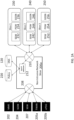
- FIG. 1 is a system diagram showing a networked system.
- FIG. 1 shows user equipment (UE) 102, RAN Node 104, mobility management entity (MME) 106, serving general packet radio services (GPRS) support node (SGSN) 108, serving gateway (SGW) 112, packet data network gateway (PGW) 114, gateway GPRS support node (GGSN) 116, domain name system (DNS) 120, Gi network 130, untrusted wireless access local area network (WLAN) 140, enhanced packet data gateway (ePDG) 142, trusted WLAN 150, and trusted WLAN access network (TWAN) 152.
- UE user equipment
- MME mobility management entity
- GPRS general packet radio services
- SGW serving gateway
- PGW packet data network gateway
- GGSN gateway GPRS support node
- DNS domain name system
- Gi untrusted wireless access local area network
- ePDG enhanced packet data gateway
- TWAN trusted WLAN access network
- UE 102 connects to a networked system 100 through the RAN Node 104, which can be an evolved NodeB (eNodeB) in 4G network, or a Radio Network Controller (RNC) for 3G or a Base Station Subsystem (BSS) for 2G.
- UE 102 includes computing devices configured to connect to a mobile data network (e.g., mobile phones, tablets, laptops).
- RAN Node 104 is a radio part of a cell site.
- a single RAN Node 104 may contain several radio transmitters, receivers, control sections and power supplies.
- RAN Node 104 can be backhauled to MME 106 and SGSN 108.
- Backhaul is a process of transferring packets or communication signals over relatively long distances to a separate location for processing, for example at a data center maintained by a network operator.
- SGSN 108 routes and forwards user data packets while also acting as the mobility anchor for a user plane during inter-RAN Node handovers.
- MME 106 is a control node in the networked system 100.
- MME 106 handles mobility and session management for the UE 102 while it is in the 4G network.
- SGSN 108 and GGSN 116 are used to route traffic in a 2G or 3G system while MME 106, SGW 112, and PGW 114 are used to route traffic in a 4G/EPC system.
- UE 102 can obtain network access via two different types of WLAN.
- WLAN 150 is trusted by the network operator, while WLAN 140 is not trusted by the network operator.
- WLANs 140, 150 link devices using wireless communications to form local area networks (LANs), for example, in limited areas.
- the WLANs 140, 150 can be integrated into the networked system 100 via ePDG 142 and TWAN 152, respectively, for communications between the WLANs 140, 150 and PGW 114 over the S2b and S2a interfaces, respectively.
- UE 102 can obtain network access using TWAN 152 and PGW 114.
- UE 102 can obtain network access using ePDG 142 and PGW 114.
- GGSN acts a serving node in a general packet radio service (GPRS) network
- PGW acts as a serving node in an evolved packet core (EPC) network.
- GPRS general packet radio service
- EPC evolved packet core
- Gi Network 130 can include any enterprise or origin servers. Gi Network 130 can connect to the internet or any other third-party server.
- DNS 120 translates domain names into IP addresses and can be queried by any of the network nodes described above.
- DNS 120 can be implemented in servers connected to network nodes over an internal or external network connection. Each of the network nodes described above can be configured to communicate with DNS 120.
- a GTP Proxy can sit between, for example, the SGW 112 and the PGW 114 and/or the SGSN 108 and the GGSN 116.
- GTP proxies can be intrusive.
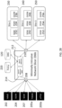
- FIG. 2A is a system diagram showing a networked system with a non-intrusive network slicer, according to some aspects of the present disclosure.
- FIG. 2A shows mobile management entity 202, Serving GPRS Support Node (SGSN) 204, TWAN 205a, ePDG 205b, network slicer 206, SGW 207, router 208, router 210, host IP addresses 212, policy server/database 220, domain name system (DNS) server/database 120 slice 1 230, serving gateway (SGW) 232, packet data network gateway (PGW) 234, Gateway GPRS Support Node (GGSN) 236, slice 2 240, serving gateway (SGW) 242, packet data network gateway (PGW) 244, Gateway GPRS Support Node (GGSN) 246, slice 3 250, serving gateway (SGW) 252, packet data network gateway (PGW) 254, and Gateway GPRS Support Node (GGSN) 256.
- SGSN Serving GPRS Support Node
- TWAN 205a e
- MME 202 functions similarly to or the same as MME 106 as shown in FIG. 1 and described in the accompanying text and SGSN 204 functions similarly to SGSN 108 as shown in FIG. 1 and described in the accompanying text.
- SGW 207, 232, 242, 252; PGW 234, 244, 254; GGSN 236, 246, 256 also function similarly to SGW 112, PGW 114, and GGSN 116 as shown in FIG. 1 and described in the accompanying text
- TWAN 205a and ePDG 205b function similarly to TWAN 152 and ePDG 142, respectively, as shown in FIG. 1 and described in the accompanying text.
- MME 202 SGSN 204
- SGW 207 TWAN 205a and ePDG 205b
- ePDG 205b ePDG 205b
- multiple of each of these elements can be included and can be connected to one or more SGWs 232, 242, 252, PGWs 234, 244, 254, and/or GGSNs 236, 246, 256.
- an SGW can be on both sides of the network slicer due to the interface it supports (S4/S11 on one side and S5/S8 on the other side).
- a network slicer 206a is introduced into the network to route traffic to and from "access-network facing nodes to data-network network facing nodes" (e.g., from left side elements to right side elements).
- Network slicer 206a can include router 208 for transmitting and receiving packets between the network slicer 206a and MME 202, SGSN 204, SGW 207, TWAN 205a, ePDG 205b, and router 210 for transmitting and receiving packets between the network slicer 206a and SGWs 232/242/252, PGWs 234/244-254, and GGSNs 236/246/256.
- the router 208 may inform the next hop router or MME, SGSN, SGW, TWAN, and ePDG directly that it has the lowest routing costs as discussed above. Thus, all traffic, regardless of type, is routed to network slicer 206a regardless of type. As shown in FIG.
- network slicer can consult one of policy 220 and DNS 120 for a policy associated with a received packet.
- network slicer 206a can inspect Create Session Requests or Create PDP Context Requests and their corresponding responses to determine if modification is required.
- Network slicer 206a routes other GTP-C packets through to the network slices without any inspection or processing. Packets from router 208 are sent to router 210 and vice versa.
- Policy 220 can be local to the network slicer 206a, an external database, or a combination of the two. Policy 220, which is explained in more detail throughout the present disclosure, can include various rules applied by the network slicer 206a.
- the request can include the MME, SGSN, SGW, TWAN, or ePDG's IP as the source IP address and the IP address of the SGW, PGW or GGSN selected by the MME, SGSN, TWAN, or ePDG as the destination IP address.
- the network slicer 206a may determine that a different SGW, PGW, or GGSN should be used based on policy 220.
- Examples of such scenarios include, but are not limited to when an operator has a dedicated slice for a particular enterprise customer (when a UE is detected to belong to the enterprise, the network slicer directs the request to the designated slice for the customer), when one slice or more slices are used for high security users (the network slicer can be configured to detect such users, for example, based on identifying characteristics, and direct request therefrom to the one or more secure slices), and when a new slice is considered to be experimental for a particular function such as high throughput (the operator may want to test that slice with particular UEs, such as internal employee devices, and the network slicer can direct employee devices to that slice using the slicer).
- An exemplary gateway-selection policy can list a specific right side element or a list of right side elements associated with a predetermined group of users.
- the policy can list one or more characteristics of a right side element to be selected (e.g., support for high speed data) for particular users, session types, etc.
- An exemplary admission-priority policy can prioritize users or groups of users when the network slicer is overloaded. For example, Create Session Requests from a particular group or groups of lower priority users may be ignored if the network slicer is overloaded (or above a threshold usage) such that the network slicer does not select new network slices for the lower priority users.
- the network slicer 206a When the network slicer 206a determines a different SGW, PGW or GGSN should be used, the network slicer 206a replaces the source IP using its own host IP 212 and the destination IP using that of the SGW or GGSN selected by the Network Slicer based on its local policy. Since the source IP is that of the network slicer 206a, the response from the SGW, PGW or GGSN will come back to the network slicer 206a.
- Slices 230, 240, 250 refer to network slices, each of which is a partitioning of a network infrastructure into multiple network infrastructures. Slices 230, 240, 250 can all be running on the same hardware platform, but implemented as separate logical networks in software. The slices can also be implemented in different hardware platform or different virtualization infra-structures.
- FIG. 2B is a system diagram showing a networked system with a minimally-intrusive network slicer, according to some aspects of the present disclosure. Elements in FIG. 2B with similar numbers to FIG. 2A function in similar ways as described herein.
- FIG. 2B differs from FIG. 2A in that a minimally-intrusive network slicer 206b includes a host IP address 214. As shown in FIG. 2B , host IP address 214 of the minimally-intrusive network slicer 206b is visible to MME 202, SGSN 204, SGW 207, TWAN 205a, and ePDG 205b. Unlike the aspect shown in FIG.
- minimally-intrusive network slicer 206b can determine the appropriate anchor node from the available network slices (e.g., by applying various policies 220 described throughout the present disclosure), and forward the message to the appropriate node by replacing its own IP 214 in the message with the destination IP of the appropriate network element in the network slices 230, 240, 250.
- the network slicer 206b can be referred to as minimally intrusive because the MMEs, SGSNs, SGW, TWANs, and ePDGs first send a create session request directed to the host IP address 214 of the network slicer 206b, whereas the initial create session requests discussed with reference to FIG. 2A are directed at network element(s) in the network slices 230, 240, or 250 but routed to network slicer because the network slicer informs the next hop routers or MME, SGSN, SGW, TWAN, and ePDG that it has lower routing costs relative to other routers to the right side elements.
- the minimally-intrusive network slicer 206b may nonetheless be considered stateless because session state information is not maintained on the network slicer, like in non-intrusive aspects. This is because both the non-intrusive network slicer 206a and the minimally intrusive network slicer 206b do not need to maintain any stored information about received or forwarded messages after sending a return message to the original left side element. Thus, in some aspects, only the left and/or right side network elements maintain session state information, while the network slicer does not. However, in other aspects, the network slicer may record, keep, or maintain session state information, or may otherwise function as a "stateful" network element.
- the network slicer 206b does not receive any traffic because MMEs, SGSNs, SGWs, TWANs, and ePDGs route directly to the selected slice that is indicated to the left side element in a return message from the networks slicer 206b, rather than directly to the host IP address 214 of the network slicer 206b and because the network slicer 206b may be implemented in a manner that does not inform next hop routers that the network slicer 206b has lower routing costs to the right side elements.
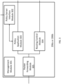
- FIG. 3 is a diagram showing a minimally or non-intrusive network slicer, according to some aspects of the present disclosure.
- FIG. 3 shows a Management module 301, a Policy Server Interface module 302, a Policy Application module 303, a Routing Control module 304 and a Packet Forwarding Module 305.
- Management module 301 provides configuration management, operation management, performance management (e.g., tracking a number of requests received, number or responses received, number of requests that have been redirected, number of responses that have been redirected, etc.) and fault management function (e.g., monitoring the health of the nodes belong to various slices, monitoring the connectivity to the policy database, generating alarms when peer nodes in the slices are down or the DB is not accessible, etc.) for the network slicer 206a or 206b.
- Management module 301 allows a user to control and monitor the network slicer 206a or 206b, including the various modules within the network slicer 206a or 206b.
- Policy application module 303 performs the application of the network slicing policy to determine the right SGW, PGW and GGSN to use for a Create Session Request or Create PDP Context Request being processed.
- policy application module 303 uses locally configured policy, which can be stored in the policy application module 303 or a storage in the network slicer 206a or 206b, as well as policies received from external servers via the Policy Server Interface module 302 to external servers, such as a subscriber policy repository (SPR), which can store subscribers' privileges and grouping information such as enterprise customer status, security level, etc.
- SPR subscriber policy repository
- Packet Forwarding module 305 inspects incoming packets. For Create Session Request or Create PDP Context Request messages and their corresponding response messages, the Packet Forwarding module sends them to the Policy application module 303. In some non-invasive aspects, for other packets, the Packet Forwarding module 305 simply forwards them to the appropriate network interface based on forwarding rules determined by the Routing Control module 304, such as IP 10.10.2.4 mask 255.255.0.0 interface port1 or IP 10.20.3.1 mask 255.255.0.0 interface port2.
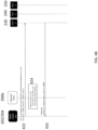
- FIGS. 4A and 4B are flow charts showing message flows for GTP-C messages that are not Create Session Request or Create PDP Context Request, according to some aspects of the present disclosure.
- the message flow in FIG. 4A can be associated with the non-intrusive network slicer 206a shown in FIG. 2A , according to some aspects.
- MME 202 routes a GTP-C that is not a Create Session Request to the network slicer 206a.
- the MME 202 may route the request to network slicer 206a because network slicer 206a informs the next hop router or MME, SGSN, SGW, TWAN, and ePDG directly that router 208 has the cheapest routing costs. Thus, all packets regardless of type are sent to the network slicer 206a.
- the received request has a source IP address associated with the MME 202 and a destination IP address of an SGW 232 in slice 1 230.
- network slicer 206a determines that the packet is not a create session request (also referred to herein "other control messages") and routes the packet to the destination IP associated with the request, which is SGW 232 in slice 1 230. In this way, the routers 208 and 210 act as normal routers.
- network slicer 206a receives a response from SGW 232 in slice 1 230, which has a source IP address associated with from SGW 232 in slice 1 and a destination address associated with MME 202.
- network slicer 206a determines that the packet is not a create session response and routes the packet to the destination IP associated with the response, which is the IP address associated with MME 202. In this way, the routers 208 and 210 act as normal routers.
- the message flow in FIG. 4B can be associated with the minimally intrusive network slicer 206b shown in FIG. 2B , according to some aspects.
- MME 202 routes a GTP-C that is not a Create Session Request to directly to the SGW 232 in slice 1 230.
- the left side element such as the MME 202
- network slicer 206b is not involved in traffic between MME 202 and SGW 232 in slice 1 230.
- the network slicer 206b is bypassed in communications between MME 202 and SGW 232 in slice 1 230.
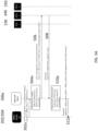
- FIGS. 5A and 5B are flow charts showing message flow for GTP-C messages that are Create Session Requests or Create PDP Context Requests for the non-intrusive network slicer 206a ( FIG. 5A ) and the minimally intrusive network slicer ( FIG. 5B ), according to some aspects of the present disclosure. Similarly labeled steps function similarly between FIGS. 5A and 5B unless otherwise noted below.
- a network element such as an MME 202 routes a GTP-C that is a create session request to the network slicer 206a/206b.
- the request has a source IP address associated with the MME 202 and a destination IP address of an SGW 232 in slice 1 230.
- the MME 202 request was routed to the network slicer 206a because the network slicer 206a informed the next hop router (e.g., a router between the left side network element and the network slicer 206a) or MME, SGSN, SGW, TWAN, and ePDG directly that the network slicer 206a has a cheaper routing cost than other routers in the network.
- the network slicer 206a may be configured to indicate a routing cost that is zero or below an expected threshold that other routers are expected to indicate. Accordingly, routers attempting to route from the left side elements to the right side elements in FIG.
- the DNS 120 is updated to include the network slicer 206b of FIG. 2B as the highest priority right side node. This can be accomplished by a manual reconfiguration during deployment, or can be performed automatically by the network slicer 206b.
- the DNS 120 will return the IP address 214 as the highest priority element even though the network slicer is not a PGW, SGW, or GGSN. Accordingly, the network slicer 206b receives initial creation messages from the left side elements to the right side elements directly at the IP address 214.
- network slicer 206a determines that the packet is a create session request and applies a policy to determine a better slice than the one indicated in the create session request.
- the network slicer 206b may not need to determine that the packet is a create request because network elements such as MME 202 only route creation requests to the network slicer 206b explicitly using IP address 214 (this can be because future messages can be routed directly to the right side element selected by the network slicer 206b).
- network slicers 206a/206b apply one or more policies to identify if a different network slice should be used.
- the network slicers 206a/206b use the information elements from the Create Session Requests and/or the source IP of the MME/SGSN as the input.
- the information used includes (but is not limited to) any one or more of IMSI, Location, Access Point Name (APN), Device id IMEI, Radio Access Technology type and Time of Day.
- Network slicer 206a/206b searches through the locally configured policies for the best match based on the above-identified information. For example, a best match can be specified by an operator that wants to use a dedicated SGW and a dedicated PGW for a particular group of users, such as those at a certain location, those with a certain IMSI, those with a certain APN type, etc.
- the locally configured policy can identify the IMSI of the users and link them to a specified SGW and PGW.
- the policy can also refer to a linkage to an external policy server.
- the network slicer 206a/206b queries the external server to determine the best slice to use.
- External servers can contain similar policies that instruct the network slicer 206a/206b to make similar selections to the locally configured policies based on similar information.
- Network slicer 206a/206b can also assign its own IP address as the source IP address for the modified Create Session Request or Create PDP Context Request.
- a person of ordinary skill in the art would understand from the present disclosure that, rather than modifying the existing Create Session Request or Create PDP Context Request, a new Create Session Request or Create PDP Context Request could be created with the required information.
- network slicer 206a/206b transmits a GTP-C create session request to the slice selected based on the policy (which is, for example, SGW 242 in slice 2 (240) in this figure) and sets the source address as the network slicer's own IP address.
- the policy which is, for example, SGW 242 in slice 2 (240) in this figure
- network slicer 206a/206b receives a response from SGW 242 in slice 2 240, which has a source IP address associated with from SGW 242 in slice 2 and a destination address associated with the network slicer 206a/206b (e.g., IP address 212).
- network slicer 206a/206b determines that the packet is a create session response and creates a new response (or modifies the existing response) with a source IP address associated with slice 1 230 (the source address expected by the MME in FIG. 5A ) or network slicer 206b (the source address expected by the MME in FIG. 5B ) and the destination IP address associated with MME 202.
- the message content from the SGW in slice 2 can already contain the IP address that the MME 202 shall use for future communications with the SGW.
- Exemplary content and relevant handling by the MME 202 are defined, for example, by 3GPP (e.g., 29.274 and 29.060).
- network slicer 206a transmits the response to MME 202 with an updated source IP (SGW 232 of slice 1 230 in FIG. 5A or network slicer 206b in FIG. 5B ) and a destination address of the MME 202. Even though the source IP indicates that the response came from slice 1 230, the content of the response is from SGW 242 of slice 2 240.
- the content includes information informing the MME 202 of the identity of the selected slice and gateway by the network slicer 206a/206b such that MME 202 can communicate with the selected slice and gateway in future messaging related to the UE session.
- the IP address of the selected slice can be included in the message content in compliance with, for example, 3GPP standards 29.274 for GTPv2 messages, or 29.060 for GTPv1 messages.
- Slice 1 and Slice 2 are two different sets of SGW, PGW and GGSNs. The slices may offer different capabilities. Slice 1 may only have an SGW, PGW and GGSN that can handle regular speed user traffic whereas Slice 2 may have an SGW, PGW and GGSN that can support higher speed user traffic.
- a network slicer 206a can be used to direct UEs that are capable of a 5G level of throughput to a high-speed slice such that the network can provide the best service to the UEs.
- multiple instances of network slicers are used in a network to provide redundancy.
- multiple slicers are introduced into the network, and, for non-intrusive aspects, subsets thereof or all of them can be treated as equal cost routes towards the SGW/PGW and GGSN. Removal or failure of one such slicer does not impact the operation of the network because the messages can be routed via other slicer instances.
- each network slicer can be given its own IP address 214. Accordingly, when one of the plural network slicers fails, the left side elements can detect the failure and use other network slicers instead.
- FIGS. 6A and 6B are flow charts showing processes of routing uplink packets in a network using non-intrusive and minimally intrusive network slicers, respectively, according to some aspects of the present disclosure.
- network slicer 206a receives a message from a first node.
- the first node can comprise one of an MME, SGW, SGSN, TWAN, or ePDG.
- network slicer 206a determines a message type associated with the first node.
- a message type can be one of a Create Session Request, Create PDP Request, or other control message (e.g., a non-Create Session request such as Modify Bearer Request, Delete Session Request etc.).
- network slicer 206a selects a network slice based on a policy of the slicer when the message type comprises a Create Session Request or a Create PDP Request.
- network slicer 206a searches for a policy in either an internal or external policy database or server based on information associated with the first node, such as one or more of IMSI, Location, Access Point Name (APN), Device ID, IMEI, Radio Access Technology type, MS-ISDN, and Time of Day.
- the network slicer may record the content of the incoming request, the target slice intended by the originating network node, the target slice selected, and/or other identifying information about the request, which can be used to populate and/or forward new response messages based on response messages received from right side elements. The use of such recorded information is described, for example, with reference to FIGs. 5A and 7 .
- the network slicer 206a may also receive non-creation request type messages. In such aspects, non-creation request type messages are routed by the routers of the network slicer without selecting a new network slice as discussed, for example, with reference to FIG. 4A .
- network slicer 206a creates a new Create Session Request or a Create PDP Request (or modifies the received request) with a different source and destination IP address different from the source and destination IP address associated with the received message.
- the source IP address associated with the new message is an IP address associated with the network slicer 206a and the destination IP address is associated with the selected network slice.
- network slicer 206a routes the new Create Session Request or a Create PDP Request to a second node of the selected network slice.
- the first node can comprise one of an MME, SGW, SGSN, TWAN, or ePDG.
- the second node can comprise one of SGW, PGW, and GGSN.
- the network slicer 206a can route traffic between at least MME and SGW, SGSN and SGW, SGSN and GGSN, SGW and PGW, TWAN and PGW, and ePDG and PGW.
- FIG. 6B shows a process for network slicer 206b that is similar to the process shown in FIG. 6A for network slicer 206a.
- network slicer 206b receives a message from a first left side node.
- the first node can comprise one of an MME, SGW, SGSN, TWAN, or ePDG. Because the network slicer 206b expects to receive creation requests directly from such network elements at at the network slicer 206b's host IP address 214 as the destination address, the network slicer 206b does not need to determine a message type associated with the message and further does not need to inform next hop routers that the network slicer 206b has lower routing costs relative to other routers.
- network slicer 206b selects a network slice based on a policy of the slicer.
- network slicer 206b searches for a policy in either an internal or external policy database or server based on information associated with the first node, such as one or more of IMSI, Location, Access Point Name (APN), Device ID, IMEI, Radio Access Technology type, MS-ISDN, and Time of Day.
- the network slicer 206b may record the content of the incoming request, the target slice intended by the originating network node, the target slice selected, and/or other identifying information about the request, which can be used to populate and/or forward new response messages based on response messages received from right side elements. The use of such recorded information is described, for example, with reference to FIGs. 5B and 7 .
- network slicer 206b creates a new Create Session Request or a Create PDP Request (or modifies the received request) with a different source and destination IP address different from the source and destination IP address associated with the received message.
- the source IP address associated with the new message is an IP address associated with the network slicer 206b and the destination IP address is associated with the selected network slice.
- network slicer 206b routes the new Create Session Request or a Create PDP Request to a second node of the selected network slice.
- the first node can comprise one of an MME, SGW, SGSN, TWAN, or ePDG.
- the second node can comprise one of SGW, PGW, and GGSN.
- the network slicer 206a can route traffic between at least MME and SGW, SGSN and SGW, SGSN and GGSN, SGW and PGW, TWAN and PGW, and ePDG and PGW.
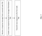
- FIG. 7 is a flow chart showing a process of routing downlink packets in a network using a non-intrusive or minimally intrusive network slicer, according to some aspects of the present disclosure.
- network slicer 206a/206b receives a Create Session Response or a Create PDP Response.
- the network slicer 206a/206b receives a Create Session Response or a Create PDP Response only for responses to requests that were routed through the network slicer 206a/206b.
- network slicer 206a/206b creates a new response (or modifies the received response) based on information recorded when the original request was processed as well as the content of the incoming response.
- the information recorded includes the IP address of the MME, SGSN, TWAN, and/or ePDG, which sent the original Create Session Request or Create PDP Context Request.
- the information also includes the destination IP address of the original Create Session Request or Create PDP Context Request.
- the recorded MME, SGSN, TWAN, and/or ePDG address becomes the destination IP address of the new response message.
- the recorded destination IP address from the original creation message can become the source IP of the new message.
- the host IP address 214 of the network slicer 206b can become the source IP address for the new message.
- the content of the incoming response message can be copied over to the new response message, but with a modification indicating that the selected slice (e.g., slice 2 in the example above) is to be used for future communications as discussed above.
- the IP address of the selected slice can be included in the message content in compliance with, for example, 3GPP standards 29.274 for GTPv2 messages, or 29.060 for GTPv1 messages.
- network slicer 206a/206b transmits the new response to the first node.
- the response includes content indicating an IP address of the selected slice and node as described above with reference to step 706.
- the network slicer 206a/206b deletes any information recorded related to the creation messages discussed with reference to FIGs. 6A / 6B and the response messages discussed with reference to FIG. 7 .
- the network no longer maintains any information related to the established session after forwarding a response message to the left side element, making the network slicer a "stateless" solution.
- the network slicer 206a/206b can also be used for the following purposes discussed below.
- the network slicers 206a and/or 206b can be used for gateway maintenance.
- the network slicer can be introduced to a running network to help migrate users from one gateway to others without impacting the service. This allows a network operator to perform upgrades, load balancing of a running network, or other tasks that can be facilitated by adaptive of controlled network slicing. Once the procedure is complete, the Network Slicer can be removed seamlessly.
- the network slicers 206a and/or 206b can be used for trouble shooting.
- the network slicer can be used to force a PDN or PDP Context to a particular set of gateways, for example, for debugging purposes .
- the same function can also be used to test new capability of a gateway or users of a gateway. For example, particular users can be onloaded or offloaded from a new or updated gateway in a controlled manner in order to test the new capabilities in a controlled manner.
- the network slicer has access to many different types of information, including, for example, IMSI, Location, Access Point Name (APN), Device id IMEI, Radio Access Technology type and Time of Day, a network operator can control the conditions of the test scenario for particular characteristics of users or other network elements.
- advantages of using network slicer 206a and/or 206b can include those described below.
- the network slicer can be transparent from the MME or SGSN's perspective. No changes to existing network function such as MME, SGSN, TWAN, ePDG, DNS server, SGW, PGW and GGSN are required. It is much easier to introduce the network slicer function as compared to traditional proxy approach. Furthermore, even for a minimally intrusive slicer, modification only needs to occur to the DNS server.
- the network slicers 206a, 206b can be stateless.
- the network slicer 206a/206b does not need to maintain the session state, rather the session state is still maintained by the MME/SGSN/TWAN/ePDG and the SGW/PGW/GGSN.
- the network slicer 206a/206b may not add another failure domain to the network. Failure of a network slicer may not impact established sessions.
- the network slicers disclosed herein can provide more comprehensive slice selection functions as compared to what can be achieved using DNS based solution on the existing MME/SGSN/TWAN/ePDG.
- the network slicer allows the operator to use any UE related information to determine the right slice to use.
- the subject matter described herein can be implemented in digital electronic circuitry, or in computer software, firmware, or hardware, including the structural means disclosed in this specification and structural equivalents thereof, or in combinations of them.
- the subject matter described herein can be implemented as one or more computer program products, such as one or more computer programs tangibly embodied in an information carrier (e.g., in a machine readable storage device), or embodied in a propagated signal, for execution by, or to control the operation of, data processing apparatus (e.g., a programmable processor, a computer, or multiple computers).
- a computer program (also known as a program, software, software application, or code) can be written in any form of programming language, including compiled or interpreted languages, and it can be deployed in any form, including as a stand-alone program or as a module, component, subroutine, or other unit suitable for use in a computing environment.
- a computer program does not necessarily correspond to a file.
- a program can be stored in a portion of a file that holds other programs or data, in a single file dedicated to the program in question, or in multiple coordinated files (e.g., files that store one or more modules, sub programs, or portions of code).
- a computer program can be deployed to be executed on one computer or on multiple computers at one site or distributed across multiple sites and interconnected by a communication network.
- processors suitable for the execution of a computer program include, by way of example, both general and special purpose microprocessors, and any one or more processor of any kind of digital computer.
- a processor will receive instructions and data from a read only memory or a random access memory or both.
- the essential elements of a computer are a processor for executing instructions and one or more memory devices for storing instructions and data.
- a computer will also include, or be operatively coupled to receive data from or transfer data to, or both, one or more mass storage devices for storing data, e.g., magnetic, magneto optical disks, or optical disks.
- Information carriers suitable for embodying computer program instructions and data include all forms of nonvolatile memory, including by way of example semiconductor memory devices, (e.g., EPROM, EEPROM, and flash memory devices); magnetic disks, (e.g., internal hard disks or removable disks); magneto optical disks; and optical disks (e.g., CD and DVD disks).
- semiconductor memory devices e.g., EPROM, EEPROM, and flash memory devices
- magnetic disks e.g., internal hard disks or removable disks
- magneto optical disks e.g., CD and DVD disks
- optical disks e.g., CD and DVD disks.
- the processor and the memory can be supplemented by, or incorporated in, special purpose logic circuitry.
- the subject matter described herein can be implemented on a computer having a display device, e.g., a CRT (cathode ray tube) or LCD (liquid crystal display) monitor, for displaying information to the user and a keyboard and a pointing device, (e.g., a mouse or a trackball), by which the user can provide input to the computer.
- a display device e.g., a CRT (cathode ray tube) or LCD (liquid crystal display) monitor
- a keyboard and a pointing device e.g., a mouse or a trackball
- Other kinds of devices can be used to provide for interaction with a user as well.
- feedback provided to the user can be any form of sensory feedback, (e.g., visual feedback, auditory feedback, or tactile feedback), and input from the user can be received in any form, including acoustic, speech, or tactile input.
- the subject matter described herein can be implemented in a computing system that includes a back end component (e.g., a data server), a middleware component (e.g., an application server), or a front end component (e.g., a client computer having a graphical user interface or a web browser through which a user can interact with an implementation of the subject matter described herein), or any combination of such back end, middleware, and front end components.
- the components of the system can be interconnected by any form or medium of digital data communication, e.g., a communication network. Examples of communication networks include a local area network ("LAN”) and a wide area network (“WAN”), e.g., the Internet.
- LAN local area network
- WAN wide area network
Landscapes
- Engineering & Computer Science (AREA)
- Computer Networks & Wireless Communication (AREA)
- Signal Processing (AREA)
- Data Exchanges In Wide-Area Networks (AREA)
- Mobile Radio Communication Systems (AREA)
Description
- The present disclosure relates generally to routing traffic in mobile networks, and in particular, to systems and methods of routing traffic using network slicing techniques.
- Some wireless operators have deployed applications known as GTP Proxy functions. A GTP Proxy typically functions as an intermediary node between different mobile network operators (MNO) and is used to aid in interoperability. As an example, a GTP Proxy can be considered an entry point for an operator's users that are roaming in other networks. A roaming network will send all the GTP related traffic, signaling and user plane, to the home GTP Proxy; from the roaming network the GTP Proxy is treated as the selected GGSN or PGW. The GTP Proxy terminates this roaming traffic and subsequently proxy the traffic to the real GGSN or PGW. In this mode of operation, the GTP Proxy hides the topology of the real GGSN/PGW(s), as well it can perform other functions of modifying and enforcement of the GTP related traffic. As the name describes the GTP Proxy always remains as an intermediary for the lifetime of a UE session; e.g. all the UE session traffic flows through the GTP Proxy.
US2007297400A1 describes a controllable port redirector comprising a stack module insertable within a communication protocol stack, preferably between the data-link and the network layer. The redirector uses a rule base, at least partially downloaded from a control host, to decide on redirection of selected packets. The invention further provides a method for communication using at least partial remotely supplied rule base. Thus communications from the computer may be remotely and transparently controlled. Optionally the invention further provide a method for providing secured communication utilizing port hopping technique, controlled by a rule set which forms a hoping order, and utilizing different rules of packets from the same transmission stream, thus increasing the difficulty in monitoring the stream as a whole. Other services that may be established by the invention include replacing certain servers like DNS servers, providing a walled garden communication environment, and the like.
APPLE ("A solution of network slice instance selection and association", 3GPP DRAFT; S2-165127, 3RD GENERATION PARTNERSHIP PROJECT (3GPP), MOBILE COMPETENCE CENTRE ; 650, ROUTE DES LUCIOLES ; F-06921 SOPHIA-ANTIPOLIS CEDEX; RANCE, vol. SA WG2, no. Sanya, P.R China; 20160829 - 20160902 3 September 2016 (2016-09-03), XP051169174, Retrieved from the Internet: URL:http://www.3gpp.org/ftp/tsg_sa/WG2_Arch/ TSGS2_ 116BIS_Sanya/Docs/ [retrieved on 2016-09-03] proposes a network slicing solution to address the NS_WT_#1, i.e. Network Slice Instance Selection and Association. - Aspects of the invention are defined in the accompanying claims.
- Various objectives, features, and advantages of the disclosed subject matter can be more fully appreciated with reference to the following detailed description of the disclosed subject matter when considered in connection with the following drawings, in which like reference numerals identify like elements.
-
FIG. 1 is a system diagram showing a networked system. -
FIGS. 2A and2B are system diagrams showing networked systems, according to some aspects of the present disclosure. -
FIG. 3 is a diagram showing a network slicer, according to some aspects of the present disclosure. -
FIGS. 4A and4B are flow charts showing message flows for GTP-C messages that are not Create Session Requests or Create PDP Context Requests, according to some aspects of the present disclosure. -
FIGS. 5A and5B are flow charts showing message flows for GTP-C messages that are Create Session Requests or Create PDP Context Requests, according to some aspects of the present disclosure. -
FIGS. 6A and6B are flow charts showing processes of routing uplink packets in a network using a non-intrusive network slicer or minimally intrusive network slicer, according to some aspects of the present disclosure. -
FIG. 7 is a flow chart showing a process of routing downlink packets in a network using a non-intrusive network slicer or minimally intrusive network slicer, according to some aspects of the present disclosure. - Systems and methods are disclosed to provide wireless network operators the ability to slice the core network into different slices such that control plane and user plane functionality can be segregated for different group of mobile users. In some aspects, the systems and methods described herein are accomplished without impacting the configurations of any of existing network functions (e.g., the function of an MME, SGSN, DNS server, serving gateway (SGW), packet data network gateway (PGW), GGSN, TWAN, and ePDG, described below). In some aspects, only updates to the DNS servers are required without impacting other network functions.
- In some aspects, network slicing techniques described herein include a flexible application that determines the correct Gateway (SGW, PGW, and/or GGSN, collectively referred to as "right side" network elements) slice to use for the UE/device PDN/PDP sessions. The application can derive, through inspection and/or receipt of the operator GTP-C signaling traffic from the MME, SGSN, SGW, TWAN, and/or ePDG (collectively referred to as "left side" network elements) to the right side elements and based on how the application is configured, the correct network slice to which to route future communications. According to some aspects, such functionality is achieved when the network slicer is inserted between at least one left side element and associated right side elements. In some aspects where the network slicer is located between the SGW (left) and the PGW (right), the network slicer only selects a PGW for future communications. Further, the SGW learns of the originally selected PGW from the MME/SGSN.
- In contrast to the GTP Proxies described above, aspects of the systems and methods described herein take a network slicing approach to flexibly classify a UE, selecting the correct network slice to anchor the UE session, establishing the Gateway association, and subsequently removing itself from the UE session traffic flow. This process can be accomplished in a non-intrusive or minimally intrusive manner such that existing mobile operator core network nodes are unaware of the presence of this new slicing application.
- In some non-intrusive aspects, a network slicer can be introduced without changes to the left side network elements or the DNS server. The network slicer can be inserted between one or more left side network elements and one or more right side network elements. The network slicer can inform a next hop router between one or more of the one or more left side network elements that it has a lower routing cost to one or more of the one or more right side network elements than other routers in the networked system that are capable of routing to the one or more of the one or more right side network elements. Accordingly, the network slier can intercept messages between the one or more of the one or more left side network elements and the one or more of the one or more right side network elements without updating a DNS server or instructing the one or more left side elements that messages should be directed to the network slicer. As described in more detail below, the non-intrusive network slicer can then inspect the messages to identify creation request messages. When creation requests messages are received, the non-intrusive network slicer selects a network slice that can, but is not necessarily, be different from the network slice selected by a left side element in the original creation request message. The non-intrusive network slicer may also receive non-creation response messages, which the non-intrusive network slicer can route in a manner consistent with routers that do not perform network slicing functions.
- In some minimally intrusive aspects, an indication can be made to a DNS server that an IP address associated with the minimally intrusive network slicer has a higher priority than one or more right side elements. Accordingly, when one or more left side elements queries the DNS server, the one or more left side elements receive an indication that the minimally intrusive network slicer has a higher priority than the right side elements to which creation messages would otherwise be routed. As described in more detail below, the one or more left side elements can then direct creation request messages to the IP address associated with the minimally intrusive network slicer. The minimally intrusive network slicer can then apply techniques describe herein to forward a creation network to a selected network slice (e.g., one or more right side elements), and return a response to the one or more left side elements that informs the one or more left side elements of which slice to direct future messages. Such future messages can be routed directly to the selected slice in a way that bypasses the network slicer. Thus, given the explanations herein, the terms "non-intrusive" and "minimally intrusive" are merely used to identify the various aspects and do not impose any further limitations on the scope of the invention.
- In some aspects, a network slicer is introduced as a
layer 3 router on its interface facing the MME, SGSN, SGW, TWAN, or ePDG, and on the interface towards the other network functions, the network slicer acts as both as a router as well as an IP host. As described in more detail below, this allows for the introduction of the network slicer without disturbing other network functions in some non-intrusive aspects. In some minimally intrusive aspects, the network slicer can be made visible on the DNS server to act as an SGW, GGSN, and/or a PGW. - In some non-intrusive aspects, when session management packets (e.g., GTP-C) from the MME, SGSN are sent to the SGWs or the GGSNs, or from SGW, TWAN or ePDG to the PGW, the network slicer informs a next hop router in front of the MME, SGSN, SGW, TWAN, and ePDG or the MME, SGSN, SGW, TWAN, and ePDG directly that it can reach the SGW, PGW, or GGSN at a lower routing cost relative to other routers in the network capable of reaching the SGW, PGW, or GGSN.
- In some aspects, the network slicer inspects incoming packets and determine if it should apply a slicing function on the incoming packets. For GTP-C packets that are not Create Session Requests (e.g., GTPv2) or Create PDP Context Request (e.g., GTPv1), the network slicer routes the packets to their destination as a router. For Create Session Requests or Create PDP Context Requests, the network slicer applies information (such as UE identities, Location, APN etc.) from the request along with locally configured policies and policies retrieved from external policy database to select which network slice should be used for the particular session. DNS servers used by the MME, SGSN, TWAN, and/or ePDG can also be sources of policy information.
- In some minimally intrusive aspects, the MME/SGSN can discover the network slicer in the same way the SGW, PGW or GGSN might be discovered, for example from a DNS server. The TWAN or ePDG can discover the network slicer in the same way the PGW might be discovered, for example from the DNS servers. The network slicer can receive the Create Session Request (e.g., via GTPv2) or Create PDP Context Request (e.g., GTPv1) without leveraging a method of altering routing cost. Once the create request packet is received, the rest of the processing can be performed in a similar way to non-intrusive aspects.
- In some aspects, once a slice is selected, the network slicer creates a new Create Session Request or Create PDP Context Request using a local host IP address and sends the request to the selected slice, which can be a different slice from what the MME, SGSN, TWAN, and/or ePDG has selected. This allows the response to come back to the network slicer, which forms a Create Session Response or Create PDP Context Response to send back to the MME, SGSN, TWAN, and/or ePDG. The source IP address used in this case is set to match the destination IP address of the original request.
-
FIG. 1 is a system diagram showing a networked system.FIG. 1 shows user equipment (UE) 102,RAN Node 104, mobility management entity (MME) 106, serving general packet radio services (GPRS) support node (SGSN) 108, serving gateway (SGW) 112, packet data network gateway (PGW) 114, gateway GPRS support node (GGSN) 116, domain name system (DNS) 120,Gi network 130, untrusted wireless access local area network (WLAN) 140, enhanced packet data gateway (ePDG) 142, trustedWLAN 150, and trusted WLAN access network (TWAN) 152. -
UE 102 connects to anetworked system 100 through theRAN Node 104, which can be an evolved NodeB (eNodeB) in 4G network, or a Radio Network Controller (RNC) for 3G or a Base Station Subsystem (BSS) for 2G.UE 102 includes computing devices configured to connect to a mobile data network (e.g., mobile phones, tablets, laptops).RAN Node 104 is a radio part of a cell site. Asingle RAN Node 104 may contain several radio transmitters, receivers, control sections and power supplies.RAN Node 104 can be backhauled toMME 106 andSGSN 108. Backhaul is a process of transferring packets or communication signals over relatively long distances to a separate location for processing, for example at a data center maintained by a network operator.SGSN 108 routes and forwards user data packets while also acting as the mobility anchor for a user plane during inter-RAN Node handovers.MME 106 is a control node in thenetworked system 100.MME 106 handles mobility and session management for theUE 102 while it is in the 4G network.SGSN 108 andGGSN 116 are used to route traffic in a 2G or 3G system whileMME 106,SGW 112, andPGW 114 are used to route traffic in a 4G/EPC system.UE 102 can obtain network access via two different types of WLAN. As shown inFIG. 1 ,WLAN 150 is trusted by the network operator, whileWLAN 140 is not trusted by the network operator.WLANs WLANs networked system 100 viaePDG 142 andTWAN 152, respectively, for communications between theWLANs PGW 114 over the S2b and S2a interfaces, respectively. For the trustedWLAN 150,UE 102 can obtain networkaccess using TWAN 152 andPGW 114. For theuntrusted WLAN 140,UE 102 can obtain networkaccess using ePDG 142 andPGW 114. - When
UE 102 attaches to the network, multiple control messages are exchanged between network elements in order to create a data session (e.g., 3G session, 4G session) and provide data connectivity to theUE 102. As explained above,RAN Node 104 can be backhauled toMME 106/SGSN 108.MME 106/SGSN 108 routes and forwards packets (e.g., user plane packets fromSGSN 108 to GGSN 116) and/or sends other messages toSGW 112,PGW 114, andGGSN 116. In some network implementations, GGSN acts a serving node in a general packet radio service (GPRS) network, and PGW acts as a serving node in an evolved packet core (EPC) network.PGW 114 andGGSN 116 route packets to and fromGi Network 130.PGW 114 can also route packets to and from theTrusted WLAN 150 andUntrusted WLAN 140 viaTWAN 152 andePDG 142, respectively.Gi Network 130 can include any enterprise or origin servers.Gi Network 130 can connect to the internet or any other third-party server. -
DNS 120 translates domain names into IP addresses and can be queried by any of the network nodes described above.DNS 120 can be implemented in servers connected to network nodes over an internal or external network connection. Each of the network nodes described above can be configured to communicate withDNS 120. - As discussed above, a GTP Proxy can sit between, for example, the
SGW 112 and thePGW 114 and/or theSGSN 108 and theGGSN 116. However, as discussed above, GTP proxies can be intrusive. -
FIG. 2A is a system diagram showing a networked system with a non-intrusive network slicer, according to some aspects of the present disclosure.FIG. 2A showsmobile management entity 202, Serving GPRS Support Node (SGSN) 204,TWAN 205a,ePDG 205b, network slicer 206,SGW 207,router 208,router 210, host IP addresses 212, policy server/database 220, domain name system (DNS) server/database 120slice 1 230, serving gateway (SGW) 232, packet data network gateway (PGW) 234, Gateway GPRS Support Node (GGSN) 236,slice 2 240, serving gateway (SGW) 242, packet data network gateway (PGW) 244, Gateway GPRS Support Node (GGSN) 246,slice 3 250, serving gateway (SGW) 252, packet data network gateway (PGW) 254, and Gateway GPRS Support Node (GGSN) 256. -
MME 202 functions similarly to or the same asMME 106 as shown inFIG. 1 and described in the accompanying text andSGSN 204 functions similarly toSGSN 108 as shown inFIG. 1 and described in the accompanying text.SGW PGW GGSN SGW 112,PGW 114, andGGSN 116 as shown inFIG. 1 and described in the accompanying text, andTWAN 205a andePDG 205b function similarly to TWAN 152 andePDG 142, respectively, as shown inFIG. 1 and described in the accompanying text. Note that although onlysingular MME 202,SGSN 204,SGW 207,TWAN 205a andePDG 205b are shown inFIG. 2A that sit at the left side of thenetwork slicer 206a, multiple of each of these elements can be included and can be connected to one or more SGWs 232, 242, 252,PGWs GGSNs FIG. 2A , an SGW can be on both sides of the network slicer due to the interface it supports (S4/S11 on one side and S5/S8 on the other side). Anetwork slicer 206a is introduced into the network to route traffic to and from "access-network facing nodes to data-network network facing nodes" (e.g., from left side elements to right side elements). -
Network slicer 206a can includerouter 208 for transmitting and receiving packets between thenetwork slicer 206a andMME 202,SGSN 204,SGW 207,TWAN 205a,ePDG 205b, androuter 210 for transmitting and receiving packets between thenetwork slicer 206a andSGWs 232/242/252,PGWs 234/244-254, andGGSNs 236/246/256. Fornetwork slicer 206a, therouter 208 may inform the next hop router or MME, SGSN, SGW, TWAN, and ePDG directly that it has the lowest routing costs as discussed above. Thus, all traffic, regardless of type, is routed to networkslicer 206a regardless of type. As shown inFIG. 2A , network slicer can consult one ofpolicy 220 andDNS 120 for a policy associated with a received packet. In particular,network slicer 206a can inspect Create Session Requests or Create PDP Context Requests and their corresponding responses to determine if modification is required.Network slicer 206a routes other GTP-C packets through to the network slices without any inspection or processing. Packets fromrouter 208 are sent torouter 210 and vice versa.Policy 220 can be local to thenetwork slicer 206a, an external database, or a combination of the two.Policy 220, which is explained in more detail throughout the present disclosure, can include various rules applied by thenetwork slicer 206a. - For example, and as described in more detail below, for an incoming Create Session Request (or Create PDP Context Request), the request can include the MME, SGSN, SGW, TWAN, or ePDG's IP as the source IP address and the IP address of the SGW, PGW or GGSN selected by the MME, SGSN, TWAN, or ePDG as the destination IP address. In some aspects, the
network slicer 206a may determine that a different SGW, PGW, or GGSN should be used based onpolicy 220. Examples of such scenarios include, but are not limited to when an operator has a dedicated slice for a particular enterprise customer (when a UE is detected to belong to the enterprise, the network slicer directs the request to the designated slice for the customer), when one slice or more slices are used for high security users (the network slicer can be configured to detect such users, for example, based on identifying characteristics, and direct request therefrom to the one or more secure slices), and when a new slice is considered to be experimental for a particular function such as high throughput (the operator may want to test that slice with particular UEs, such as internal employee devices, and the network slicer can direct employee devices to that slice using the slicer). An exemplary gateway-selection policy can list a specific right side element or a list of right side elements associated with a predetermined group of users. In another exemplary gateway-selection policy, the policy can list one or more characteristics of a right side element to be selected (e.g., support for high speed data) for particular users, session types, etc. An exemplary admission-priority policy can prioritize users or groups of users when the network slicer is overloaded. For example, Create Session Requests from a particular group or groups of lower priority users may be ignored if the network slicer is overloaded (or above a threshold usage) such that the network slicer does not select new network slices for the lower priority users. When thenetwork slicer 206a determines a different SGW, PGW or GGSN should be used, thenetwork slicer 206a replaces the source IP using itsown host IP 212 and the destination IP using that of the SGW or GGSN selected by the Network Slicer based on its local policy. Since the source IP is that of thenetwork slicer 206a, the response from the SGW, PGW or GGSN will come back to thenetwork slicer 206a. At that time, it replaces the destination IP using that of the MME, SGSN, SGW, TWAN, or ePDG from which the original request was received, and the source IP using the IP Address of the SGW or GGSN selected by the MME, SGSN, TWAN, or ePDG such that the source IP address of the response is the destination IP address of the original request. -
Slices Slices -
FIG. 2B is a system diagram showing a networked system with a minimally-intrusive network slicer, according to some aspects of the present disclosure. Elements inFIG. 2B with similar numbers toFIG. 2A function in similar ways as described herein. In some aspects,FIG. 2B differs fromFIG. 2A in that a minimally-intrusive network slicer 206b includes ahost IP address 214. As shown inFIG. 2B ,host IP address 214 of the minimally-intrusive network slicer 206b is visible toMME 202,SGSN 204,SGW 207,TWAN 205a, andePDG 205b. Unlike the aspect shown inFIG. 2A ,MME 202,SGSN 204,SGW 207,TWAN 205a, andePDG 205b may be modified to transmit creation session request messages directly to thehost IP address 214 of the minimally-intrusive network slicer 206b. As discussed above with reference tonon-intrusive network slicer 206a, minimally-intrusive network slicer 206b can determine the appropriate anchor node from the available network slices (e.g., by applyingvarious policies 220 described throughout the present disclosure), and forward the message to the appropriate node by replacing itsown IP 214 in the message with the destination IP of the appropriate network element in the network slices 230, 240, 250. Thenetwork slicer 206b can be referred to as minimally intrusive because the MMEs, SGSNs, SGW, TWANs, and ePDGs first send a create session request directed to thehost IP address 214 of thenetwork slicer 206b, whereas the initial create session requests discussed with reference toFIG. 2A are directed at network element(s) in the network slices 230, 240, or 250 but routed to network slicer because the network slicer informs the next hop routers or MME, SGSN, SGW, TWAN, and ePDG that it has lower routing costs relative to other routers to the right side elements. However, the minimally-intrusive network slicer 206b may nonetheless be considered stateless because session state information is not maintained on the network slicer, like in non-intrusive aspects. This is because both thenon-intrusive network slicer 206a and the minimallyintrusive network slicer 206b do not need to maintain any stored information about received or forwarded messages after sending a return message to the original left side element. Thus, in some aspects, only the left and/or right side network elements maintain session state information, while the network slicer does not. However, in other aspects, the network slicer may record, keep, or maintain session state information, or may otherwise function as a "stateful" network element. In some aspects, for non-creation requests, thenetwork slicer 206b does not receive any traffic because MMEs, SGSNs, SGWs, TWANs, and ePDGs route directly to the selected slice that is indicated to the left side element in a return message from thenetworks slicer 206b, rather than directly to thehost IP address 214 of thenetwork slicer 206b and because thenetwork slicer 206b may be implemented in a manner that does not inform next hop routers that thenetwork slicer 206b has lower routing costs to the right side elements. -
FIG. 3 is a diagram showing a minimally or non-intrusive network slicer, according to some aspects of the present disclosure.FIG. 3 shows aManagement module 301, a PolicyServer Interface module 302, aPolicy Application module 303, aRouting Control module 304 and aPacket Forwarding Module 305. -
Management module 301 provides configuration management, operation management, performance management (e.g., tracking a number of requests received, number or responses received, number of requests that have been redirected, number of responses that have been redirected, etc.) and fault management function (e.g., monitoring the health of the nodes belong to various slices, monitoring the connectivity to the policy database, generating alarms when peer nodes in the slices are down or the DB is not accessible, etc.) for thenetwork slicer Management module 301 allows a user to control and monitor thenetwork slicer network slicer -
Policy application module 303 performs the application of the network slicing policy to determine the right SGW, PGW and GGSN to use for a Create Session Request or Create PDP Context Request being processed. In some aspects,policy application module 303 uses locally configured policy, which can be stored in thepolicy application module 303 or a storage in thenetwork slicer Server Interface module 302 to external servers, such as a subscriber policy repository (SPR), which can store subscribers' privileges and grouping information such as enterprise customer status, security level, etc. -
Packet Forwarding module 305 inspects incoming packets. For Create Session Request or Create PDP Context Request messages and their corresponding response messages, the Packet Forwarding module sends them to thePolicy application module 303. In some non-invasive aspects, for other packets, thePacket Forwarding module 305 simply forwards them to the appropriate network interface based on forwarding rules determined by theRouting Control module 304, such as IP 10.10.2.4 mask 255.255.0.0 interface port1 or IP 10.20.3.1 mask 255.255.0.0 interface port2. -
FIGS. 4A and4B are flow charts showing message flows for GTP-C messages that are not Create Session Request or Create PDP Context Request, according to some aspects of the present disclosure. The message flow inFIG. 4A can be associated with thenon-intrusive network slicer 206a shown inFIG. 2A , according to some aspects. - Referring to step 402,
MME 202 routes a GTP-C that is not a Create Session Request to thenetwork slicer 206a. TheMME 202 may route the request to network slicer 206a becausenetwork slicer 206a informs the next hop router or MME, SGSN, SGW, TWAN, and ePDG directly thatrouter 208 has the cheapest routing costs. Thus, all packets regardless of type are sent to thenetwork slicer 206a. The received request has a source IP address associated with theMME 202 and a destination IP address of anSGW 232 inslice 1 230. - Referring to step 404,
network slicer 206a determines that the packet is not a create session request (also referred to herein "other control messages") and routes the packet to the destination IP associated with the request, which isSGW 232 inslice 1 230. In this way, therouters - Referring to step 406,
network slicer 206a receives a response fromSGW 232 inslice 1 230, which has a source IP address associated with fromSGW 232 inslice 1 and a destination address associated withMME 202. - Referring to step 408,
network slicer 206a determines that the packet is not a create session response and routes the packet to the destination IP associated with the response, which is the IP address associated withMME 202. In this way, therouters - The message flow in
FIG. 4B can be associated with the minimallyintrusive network slicer 206b shown inFIG. 2B , according to some aspects. As shown inFIG. 4B , referring to step 422,MME 202 routes a GTP-C that is not a Create Session Request to directly to theSGW 232 inslice 1 230. This is because, as described in more detail below, the left side element, such as theMME 202, will have received an indication in a response message of a selected slice, and will route traffic directly to that selected slice. Referring to step 424,network slicer 206b is not involved in traffic betweenMME 202 andSGW 232 inslice 1 230. Similarly, instep 432, thenetwork slicer 206b is bypassed in communications betweenMME 202 andSGW 232 inslice 1 230. -
FIGS. 5A and5B are flow charts showing message flow for GTP-C messages that are Create Session Requests or Create PDP Context Requests for the non-intrusive network slicer 206a (FIG. 5A ) and the minimally intrusive network slicer (FIG. 5B ), according to some aspects of the present disclosure. Similarly labeled steps function similarly betweenFIGS. 5A and5B unless otherwise noted below. - Referring to
steps MME 202 routes a GTP-C that is a create session request to thenetwork slicer 206a/206b. The request has a source IP address associated with theMME 202 and a destination IP address of anSGW 232 inslice 1 230. In some aspects, as shown in the non-intrusive aspect ofFIG. 5A , theMME 202 request was routed to thenetwork slicer 206a because thenetwork slicer 206a informed the next hop router (e.g., a router between the left side network element and thenetwork slicer 206a) or MME, SGSN, SGW, TWAN, and ePDG directly that thenetwork slicer 206a has a cheaper routing cost than other routers in the network. Thenetwork slicer 206a may be configured to indicate a routing cost that is zero or below an expected threshold that other routers are expected to indicate. Accordingly, routers attempting to route from the left side elements to the right side elements inFIG. 2A will route messages, including creation messages and non-creation messages, through thenetwork slicer 206a because the routers see thenetwork slicer 206a as having lower routing costs to the network slices relative to other routers. As shown inFIG. 5B , during deployment of thenetwork slicer 206b, theDNS 120 is updated to include thenetwork slicer 206b ofFIG. 2B as the highest priority right side node. This can be accomplished by a manual reconfiguration during deployment, or can be performed automatically by thenetwork slicer 206b. Thus, when a left side element queries the DNS for a right side element to send the creation request, theDNS 120 will return theIP address 214 as the highest priority element even though the network slicer is not a PGW, SGW, or GGSN. Accordingly, thenetwork slicer 206b receives initial creation messages from the left side elements to the right side elements directly at theIP address 214. - Referring to step 504a,
network slicer 206a determines that the packet is a create session request and applies a policy to determine a better slice than the one indicated in the create session request. Instep 504b, thenetwork slicer 206b may not need to determine that the packet is a create request because network elements such asMME 202 only route creation requests to thenetwork slicer 206b explicitly using IP address 214 (this can be because future messages can be routed directly to the right side element selected by thenetwork slicer 206b). Insteps network slicers 206a/206b apply one or more policies to identify if a different network slice should be used. In some aspects, thenetwork slicers 206a/206b use the information elements from the Create Session Requests and/or the source IP of the MME/SGSN as the input. The information used includes (but is not limited to) any one or more of IMSI, Location, Access Point Name (APN), Device id IMEI, Radio Access Technology type and Time of Day.Network slicer 206a/206b then searches through the locally configured policies for the best match based on the above-identified information. For example, a best match can be specified by an operator that wants to use a dedicated SGW and a dedicated PGW for a particular group of users, such as those at a certain location, those with a certain IMSI, those with a certain APN type, etc. The locally configured policy can identify the IMSI of the users and link them to a specified SGW and PGW. The policy can also refer to a linkage to an external policy server. Thenetwork slicer 206a/206b then queries the external server to determine the best slice to use. External servers can contain similar policies that instruct thenetwork slicer 206a/206b to make similar selections to the locally configured policies based on similar information.Network slicer 206a/206b can also assign its own IP address as the source IP address for the modified Create Session Request or Create PDP Context Request. A person of ordinary skill in the art would understand from the present disclosure that, rather than modifying the existing Create Session Request or Create PDP Context Request, a new Create Session Request or Create PDP Context Request could be created with the required information. - Referring to step 506,
network slicer 206a/206b transmits a GTP-C create session request to the slice selected based on the policy (which is, for example,SGW 242 in slice 2 (240) in this figure) and sets the source address as the network slicer's own IP address. - Referring to step 508,
network slicer 206a/206b receives a response fromSGW 242 inslice 2 240, which has a source IP address associated with fromSGW 242 inslice 2 and a destination address associated with thenetwork slicer 206a/206b (e.g., IP address 212). - Referring to
steps network slicer 206a/206b determines that the packet is a create session response and creates a new response (or modifies the existing response) with a source IP address associated withslice 1 230 (the source address expected by the MME inFIG. 5A ) ornetwork slicer 206b (the source address expected by the MME inFIG. 5B ) and the destination IP address associated withMME 202. In some aspects, the message content from the SGW inslice 2 can already contain the IP address that theMME 202 shall use for future communications with the SGW. Exemplary content and relevant handling by theMME 202 are defined, for example, by 3GPP (e.g., 29.274 and 29.060). - Referring to
steps network slicer 206a transmits the response toMME 202 with an updated source IP (SGW 232 ofslice 1 230 inFIG. 5A ornetwork slicer 206b inFIG. 5B ) and a destination address of theMME 202. Even though the source IP indicates that the response came fromslice 1 230, the content of the response is fromSGW 242 ofslice 2 240. The content includes information informing theMME 202 of the identity of the selected slice and gateway by thenetwork slicer 206a/206b such thatMME 202 can communicate with the selected slice and gateway in future messaging related to the UE session. In some aspects, the IP address of the selected slice can be included in the message content in compliance with, for example, 3GPP standards 29.274 for GTPv2 messages, or 29.060 for GTPv1 messages. In some aspects,Slice 1 andSlice 2 are two different sets of SGW, PGW and GGSNs. The slices may offer different capabilities.Slice 1 may only have an SGW, PGW and GGSN that can handle regular speed user traffic whereasSlice 2 may have an SGW, PGW and GGSN that can support higher speed user traffic. Anetwork slicer 206a can be used to direct UEs that are capable of a 5G level of throughput to a high-speed slice such that the network can provide the best service to the UEs. - In some aspects, multiple instances of network slicers are used in a network to provide redundancy. In such a redundant aspect, multiple slicers are introduced into the network, and, for non-intrusive aspects, subsets thereof or all of them can be treated as equal cost routes towards the SGW/PGW and GGSN. Removal or failure of one such slicer does not impact the operation of the network because the messages can be routed via other slicer instances. In some minimally intrusive aspects, each network slicer can be given its
own IP address 214. Accordingly, when one of the plural network slicers fails, the left side elements can detect the failure and use other network slicers instead. -
FIGS. 6A and6B are flow charts showing processes of routing uplink packets in a network using non-intrusive and minimally intrusive network slicers, respectively, according to some aspects of the present disclosure. - Referring to step 602,
network slicer 206a receives a message from a first node. In some aspects, the first node can comprise one of an MME, SGW, SGSN, TWAN, or ePDG. - Referring to step 604,
network slicer 206a determines a message type associated with the first node. A message type can be one of a Create Session Request, Create PDP Request, or other control message (e.g., a non-Create Session request such as Modify Bearer Request, Delete Session Request etc.). - Referring to step 606,
network slicer 206a selects a network slice based on a policy of the slicer when the message type comprises a Create Session Request or a Create PDP Request. As described above, when the message type comprises a Create Session Request or a Create PDP Request,network slicer 206a searches for a policy in either an internal or external policy database or server based on information associated with the first node, such as one or more of IMSI, Location, Access Point Name (APN), Device ID, IMEI, Radio Access Technology type, MS-ISDN, and Time of Day. In some aspects, the network slicer may record the content of the incoming request, the target slice intended by the originating network node, the target slice selected, and/or other identifying information about the request, which can be used to populate and/or forward new response messages based on response messages received from right side elements. The use of such recorded information is described, for example, with reference toFIGs. 5A and7 . In some non-intrusive aspects, thenetwork slicer 206a may also receive non-creation request type messages. In such aspects, non-creation request type messages are routed by the routers of the network slicer without selecting a new network slice as discussed, for example, with reference toFIG. 4A . - Referring to step 608,
network slicer 206a creates a new Create Session Request or a Create PDP Request (or modifies the received request) with a different source and destination IP address different from the source and destination IP address associated with the received message. For example, the source IP address associated with the new message is an IP address associated with thenetwork slicer 206a and the destination IP address is associated with the selected network slice. - Referring to step 610,
network slicer 206a routes the new Create Session Request or a Create PDP Request to a second node of the selected network slice. As described above, in some aspects, the first node can comprise one of an MME, SGW, SGSN, TWAN, or ePDG. In some aspects, the second node can comprise one of SGW, PGW, and GGSN. Thenetwork slicer 206a can route traffic between at least MME and SGW, SGSN and SGW, SGSN and GGSN, SGW and PGW, TWAN and PGW, and ePDG and PGW. -
FIG. 6B shows a process fornetwork slicer 206b that is similar to the process shown inFIG. 6A fornetwork slicer 206a. - Referring to step 612,
network slicer 206b receives a message from a first left side node. In some aspects, the first node can comprise one of an MME, SGW, SGSN, TWAN, or ePDG. Because thenetwork slicer 206b expects to receive creation requests directly from such network elements at at thenetwork slicer 206b'shost IP address 214 as the destination address, thenetwork slicer 206b does not need to determine a message type associated with the message and further does not need to inform next hop routers that thenetwork slicer 206b has lower routing costs relative to other routers. - Referring to step 616,
network slicer 206b selects a network slice based on a policy of the slicer. As described above,network slicer 206b searches for a policy in either an internal or external policy database or server based on information associated with the first node, such as one or more of IMSI, Location, Access Point Name (APN), Device ID, IMEI, Radio Access Technology type, MS-ISDN, and Time of Day. In some aspects, thenetwork slicer 206b may record the content of the incoming request, the target slice intended by the originating network node, the target slice selected, and/or other identifying information about the request, which can be used to populate and/or forward new response messages based on response messages received from right side elements. The use of such recorded information is described, for example, with reference toFIGs. 5B and7 . - Referring to step 618,
network slicer 206b creates a new Create Session Request or a Create PDP Request (or modifies the received request) with a different source and destination IP address different from the source and destination IP address associated with the received message. For example, the source IP address associated with the new message is an IP address associated with thenetwork slicer 206b and the destination IP address is associated with the selected network slice. - Referring to step 620,
network slicer 206b routes the new Create Session Request or a Create PDP Request to a second node of the selected network slice. As described above, in some aspects, the first node can comprise one of an MME, SGW, SGSN, TWAN, or ePDG. In some aspects, the second node can comprise one of SGW, PGW, and GGSN. Thenetwork slicer 206a can route traffic between at least MME and SGW, SGSN and SGW, SGSN and GGSN, SGW and PGW, TWAN and PGW, and ePDG and PGW. -
FIG. 7 is a flow chart showing a process of routing downlink packets in a network using a non-intrusive or minimally intrusive network slicer, according to some aspects of the present disclosure. - Referring to step 702,
network slicer 206a/206b receives a Create Session Response or a Create PDP Response. Thenetwork slicer 206a/206b receives a Create Session Response or a Create PDP Response only for responses to requests that were routed through thenetwork slicer 206a/206b. - Referring to step 704,
network slicer 206a/206b creates a new response (or modifies the received response) based on information recorded when the original request was processed as well as the content of the incoming response. The information recorded includes the IP address of the MME, SGSN, TWAN, and/or ePDG, which sent the original Create Session Request or Create PDP Context Request. The information also includes the destination IP address of the original Create Session Request or Create PDP Context Request. In some aspects, the recorded MME, SGSN, TWAN, and/or ePDG address becomes the destination IP address of the new response message. Fornetwork slicer 206a, the recorded destination IP address from the original creation message can become the source IP of the new message. For thenetwork slicer 206b, thehost IP address 214 of thenetwork slicer 206b can become the source IP address for the new message. The content of the incoming response message can be copied over to the new response message, but with a modification indicating that the selected slice (e.g.,slice 2 in the example above) is to be used for future communications as discussed above. The IP address of the selected slice can be included in the message content in compliance with, for example, 3GPP standards 29.274 for GTPv2 messages, or 29.060 for GTPv1 messages. - Referring to step 706,
network slicer 206a/206b transmits the new response to the first node. In some aspects, the response includes content indicating an IP address of the selected slice and node as described above with reference to step 706. By providing this information, further messages sent by the first node to the network can be directed to the selected second node. In some aspects, atstep 706, thenetwork slicer 206a/206b deletes any information recorded related to the creation messages discussed with reference toFIGs. 6A /6B and the response messages discussed with reference toFIG. 7 . Thus the network no longer maintains any information related to the established session after forwarding a response message to the left side element, making the network slicer a "stateless" solution. - In addition to the network slicing capabilities described above, the
network slicer 206a/206b can also be used for the following purposes discussed below. - According to some aspects, the
network slicers 206a and/or 206b can be used for gateway maintenance. The network slicer can be introduced to a running network to help migrate users from one gateway to others without impacting the service. This allows a network operator to perform upgrades, load balancing of a running network, or other tasks that can be facilitated by adaptive of controlled network slicing. Once the procedure is complete, the Network Slicer can be removed seamlessly. - According to some aspects, the
network slicers 206a and/or 206b can be used for trouble shooting. The network slicer can be used to force a PDN or PDP Context to a particular set of gateways, for example, for debugging purposes . The same function can also be used to test new capability of a gateway or users of a gateway. For example, particular users can be onloaded or offloaded from a new or updated gateway in a controlled manner in order to test the new capabilities in a controlled manner. Because the network slicer has access to many different types of information, including, for example, IMSI, Location, Access Point Name (APN), Device id IMEI, Radio Access Technology type and Time of Day, a network operator can control the conditions of the test scenario for particular characteristics of users or other network elements. - In some aspects, advantages of using
network slicer 206a and/or 206b can include those described below. - In some aspects, the network slicer can be transparent from the MME or SGSN's perspective. No changes to existing network function such as MME, SGSN, TWAN, ePDG, DNS server, SGW, PGW and GGSN are required. It is much easier to introduce the network slicer function as compared to traditional proxy approach. Furthermore, even for a minimally intrusive slicer, modification only needs to occur to the DNS server.
- In some aspects, the
network slicers network slicer 206a/206b does not need to maintain the session state, rather the session state is still maintained by the MME/SGSN/TWAN/ePDG and the SGW/PGW/GGSN. Thus, thenetwork slicer 206a/206b may not add another failure domain to the network. Failure of a network slicer may not impact established sessions. - In some aspects, the network slicers disclosed herein can provide more comprehensive slice selection functions as compared to what can be achieved using DNS based solution on the existing MME/SGSN/TWAN/ePDG. The network slicer allows the operator to use any UE related information to determine the right slice to use.
- The subject matter described herein can be implemented in digital electronic circuitry, or in computer software, firmware, or hardware, including the structural means disclosed in this specification and structural equivalents thereof, or in combinations of them. The subject matter described herein can be implemented as one or more computer program products, such as one or more computer programs tangibly embodied in an information carrier (e.g., in a machine readable storage device), or embodied in a propagated signal, for execution by, or to control the operation of, data processing apparatus (e.g., a programmable processor, a computer, or multiple computers). A computer program (also known as a program, software, software application, or code) can be written in any form of programming language, including compiled or interpreted languages, and it can be deployed in any form, including as a stand-alone program or as a module, component, subroutine, or other unit suitable for use in a computing environment. A computer program does not necessarily correspond to a file. A program can be stored in a portion of a file that holds other programs or data, in a single file dedicated to the program in question, or in multiple coordinated files (e.g., files that store one or more modules, sub programs, or portions of code). A computer program can be deployed to be executed on one computer or on multiple computers at one site or distributed across multiple sites and interconnected by a communication network.
- The processes and logic flows described in this specification, including the method steps of the subject matter described herein, can be performed by one or more programmable processors executing one or more computer programs to perform functions of the subject matter described herein by operating on input data and generating output. The processes and logic flows can also be performed by, and apparatus of the subject matter described herein can be implemented as, special purpose logic circuitry, e.g., an FPGA (field programmable gate array) or an ASIC (application specific integrated circuit).
- Processors suitable for the execution of a computer program include, by way of example, both general and special purpose microprocessors, and any one or more processor of any kind of digital computer. Generally, a processor will receive instructions and data from a read only memory or a random access memory or both. The essential elements of a computer are a processor for executing instructions and one or more memory devices for storing instructions and data. Generally, a computer will also include, or be operatively coupled to receive data from or transfer data to, or both, one or more mass storage devices for storing data, e.g., magnetic, magneto optical disks, or optical disks. Information carriers suitable for embodying computer program instructions and data include all forms of nonvolatile memory, including by way of example semiconductor memory devices, (e.g., EPROM, EEPROM, and flash memory devices); magnetic disks, (e.g., internal hard disks or removable disks); magneto optical disks; and optical disks (e.g., CD and DVD disks). The processor and the memory can be supplemented by, or incorporated in, special purpose logic circuitry.
- To provide for interaction with a user, the subject matter described herein can be implemented on a computer having a display device, e.g., a CRT (cathode ray tube) or LCD (liquid crystal display) monitor, for displaying information to the user and a keyboard and a pointing device, (e.g., a mouse or a trackball), by which the user can provide input to the computer. Other kinds of devices can be used to provide for interaction with a user as well. For example, feedback provided to the user can be any form of sensory feedback, (e.g., visual feedback, auditory feedback, or tactile feedback), and input from the user can be received in any form, including acoustic, speech, or tactile input.
- The subject matter described herein can be implemented in a computing system that includes a back end component (e.g., a data server), a middleware component (e.g., an application server), or a front end component (e.g., a client computer having a graphical user interface or a web browser through which a user can interact with an implementation of the subject matter described herein), or any combination of such back end, middleware, and front end components. The components of the system can be interconnected by any form or medium of digital data communication, e.g., a communication network. Examples of communication networks include a local area network ("LAN") and a wide area network ("WAN"), e.g., the Internet.
- It is to be understood that the disclosed subject matter is not limited in its application to the details of construction and to the arrangements of the components set forth in the following description or illustrated in the drawings. The disclosed subject matter is capable of other aspects and of being practiced and carried out in various ways. Also, it is to be understood that the phraseology and terminology employed herein are for the purpose of description and should not be regarded as limiting.
- As such, those skilled in the art will appreciate that the conception, upon which this disclosure is based, may readily be utilized as a basis for the designing of other structures, methods, and systems for carrying out the several purposes of the disclosed subject matter.
- Although the disclosed subject matter has been described and illustrated in the foregoing exemplary aspects, it is understood that the present disclosure has been made only by way of example, and that numerous changes in the details of implementation of the disclosed subject matter may be made.
Claims (10)
- A method comprising:receiving (602), at a network slicer (206a) in a networked system, a first message from a first network node of the networked system;determining, by the network slicer, a destination address from the first message: determining (604), by the network slicer, if a message type of the first message is a predetermined message type;if the determined message type of the first message is not the predetermined message type, routing the first message to a second network node of the networked system associated with the destination address; andif the determined message type of the first message is the predetermined message type:determining a destination type from the first message,identifying, based on one or more of a policy of the network slicer or an external policy, a second network node in a network slice selected by the network slicer of the networked system having the destination type,creating (608), by the network slicer, a new message of the predetermined message type wherein a source address of the new message is a network slicer address, and wherein a destination address of the new message is a second network node address; androuting (610) the new message of the predetermined message type to the second network nodewherein the network slicer functions as both as a router and an IP host;and wherein the network slicer is located between access-network facing nodes and data-network network facing nodes in the networked system.
- The method of claim 1, wherein the predetermined message type is a creation request message.
- The method of claim 1, wherein the first network node is one or more of a mobility management entity, MME, a serving general packet radio services, GPRS, support node, SGSN, serving gateway, SGW, enhanced packet data gateway, ePDG, or a trusted WLAN.
- The method of claim 1, wherein the determined destination type comprises a gateway general packet radio services, GPRS, support node,GGSN a serving gateway, SGW, or a packet data network gateway, PGW.
- The method of claim 1, wherein identifying the second network node comprises:determining, by the network slicer, one or more of a throughput capability level of a user equipment, UE,associated with the first message, an enterprise associated with the UE associated with the first message, a traffic speed of the UE associated with the first message, a security level or requirement of the UE associated with the first message, or an employee status of the owner of the UE associated with the first message, andselecting, by the network slicer, the destination address associated with one or more of a capability level of the UE, an enterprise of the UE, the traffic speed of the UE, the security level or requirement of the UE, or the employee status of the owner of the UE from a plurality of destination addresses.
- The method of claim 1, wherein identifying the second network node comprises determining one or more of an International Mobile Subscriber Identity, IMSI, of a user equipment associated with the first message, location of the user equipment associated with the first message, access point name, APN, associated with the first message, an International Equipment Identity. IMEI, identification number of the user equipment associated with the first message, a Radio Access Technology type associated with the first message, or a timestamp of the first message.
- The method of claim 1, further comprising:receiving, by the network slicer, a response message from the second network node; andcreating, by the network slicer, a new response message including:a third network node as the source address of the new response message, andan indication of the second network node in the message content of the new response message, wherein the third network node is either the network slicer or the second network node.
- The method of claim 7, further comprising:storing, at the network slicer, one or more of an address associated with the first network node or the destination address prior to the receiving the response message from the third network node; anddeleting, by the network slicer, at least one address associated with the first network node or the destination address after the new response message is created.
- The method of claim 1, further comprising indicating to a next hop router by the network slicer that a router associated with the network slicer has a lower routing cost to the second network node than an expected routing cost from other routers in the networked system to the second network node prior to the receiving the first message, wherein the lower routing cost to the second network node is lower than an actual routing cost to the second network node.
- A network slicer in a networked system, the network slicer comprising:a processor; anda storage medium having instructions contained thereon that cause the processor to perform the steps of the method of any preceding claim.
Applications Claiming Priority (2)
| Application Number | Priority Date | Filing Date | Title |
|---|---|---|---|
| US201862645484P | 2018-03-20 | 2018-03-20 | |
| PCT/US2019/023138 WO2019183206A1 (en) | 2018-03-20 | 2019-03-20 | Systems and methods for network slicing |
Publications (2)
| Publication Number | Publication Date |
|---|---|
| EP3769476A1 EP3769476A1 (en) | 2021-01-27 |
| EP3769476B1 true EP3769476B1 (en) | 2024-08-28 |
Family
ID=66049710
Family Applications (1)
| Application Number | Title | Priority Date | Filing Date |
|---|---|---|---|
| EP19716034.4A Active EP3769476B1 (en) | 2018-03-20 | 2019-03-20 | Systems and methods for network slicing |
Country Status (14)
| Country | Link |
|---|---|
| US (1) | US11516113B2 (en) |
| EP (1) | EP3769476B1 (en) |
| JP (1) | JP7325432B2 (en) |
| KR (1) | KR102692166B1 (en) |
| CN (1) | CN111869170B (en) |
| AU (1) | AU2019238187B2 (en) |
| BR (1) | BR112020018950A2 (en) |
| CA (1) | CA3092370A1 (en) |
| IL (1) | IL277298B2 (en) |
| MX (1) | MX2020009728A (en) |
| MY (1) | MY205913A (en) |
| PH (1) | PH12020551512A1 (en) |
| SG (1) | SG11202008717SA (en) |
| WO (1) | WO2019183206A1 (en) |
Families Citing this family (8)
| Publication number | Priority date | Publication date | Assignee | Title |
|---|---|---|---|---|
| US10863410B1 (en) * | 2018-03-28 | 2020-12-08 | F5 Networks, Inc. | Methods for packet data network service slicing with microsegmentation in an evolved packet core and devices thereof |
| CN109412951B (en) * | 2018-10-12 | 2021-06-22 | 华为技术有限公司 | Method and device for sending routing information |
| KR102829766B1 (en) * | 2019-06-17 | 2025-07-04 | 삼성전자 주식회사 | Method for processing concurrent location information service request of termianl in mobile communication system |
| KR102231374B1 (en) * | 2019-07-12 | 2021-03-23 | 에스케이텔레콤 주식회사 | Multi access edge computing orchestrator, and control method thereof |
| US11070422B2 (en) | 2019-09-16 | 2021-07-20 | Cisco Technology, Inc. | Enabling enterprise segmentation with 5G slices in a service provider network |
| CN114554540B (en) * | 2020-11-24 | 2025-02-18 | 上海中兴软件有限责任公司 | Network slicing access method, device, system and storage medium |
| US12034570B2 (en) | 2022-03-14 | 2024-07-09 | T-Mobile Usa, Inc. | Multi-element routing system for mobile communications |
| US12439331B2 (en) * | 2022-03-30 | 2025-10-07 | Rakuten Mobile, Inc. | Communication route determination system and communication route determination method |
Family Cites Families (207)
| Publication number | Priority date | Publication date | Assignee | Title |
|---|---|---|---|---|
| CA2269061A1 (en) | 1996-10-18 | 1998-04-30 | Axiohm Transaction Solutions, Inc. | Printing apparatus |
| AU2001261141A1 (en) | 2000-05-02 | 2001-11-12 | Sun Microsystems, Inc. | Method and system for achieving high availability in a networked computer system |
| WO2002001473A1 (en) | 2000-06-26 | 2002-01-03 | Tradingscreen, Inc. | Securities trade state tracking method and apparatus |
| US7698463B2 (en) | 2000-09-12 | 2010-04-13 | Sri International | System and method for disseminating topology and link-state information to routing nodes in a mobile ad hoc network |
| US20020107966A1 (en) | 2001-02-06 | 2002-08-08 | Jacques Baudot | Method and system for maintaining connections in a network |
| US7346840B1 (en) | 2001-02-26 | 2008-03-18 | Cisco Technology, Inc. | Application server configured for dynamically generating web forms based on extensible markup language documents and retrieved subscriber data |
| US20020176378A1 (en) | 2001-05-22 | 2002-11-28 | Hamilton Thomas E. | Platform and method for providing wireless data services |
| US20030171114A1 (en) | 2002-03-05 | 2003-09-11 | Hastings David C. | Optimized wireless LAN solution for embedded systems |
| US7734746B2 (en) | 2002-03-18 | 2010-06-08 | Panasonic Corporation | Method and apparatus for configuring and controlling network resources in content delivery with distributed rules |
| US20030187982A1 (en) | 2002-03-27 | 2003-10-02 | Patrick Petit | System and method for resource load balancing in a portal server |
| ATE354241T1 (en) | 2002-06-19 | 2007-03-15 | Motorola Inc | METHOD AND DEVICE FOR ROUTE OPTIMIZATION IN NESTED MOBILE NETWORKS |
| FI20021287A0 (en) | 2002-06-28 | 2002-06-28 | Nokia Corp | Load sharing in a telecommunications system |
| AU2003243106A1 (en) | 2002-10-15 | 2004-05-04 | Hegdahl, Tormod | System for providing flexible charging in a network |
| US20060294238A1 (en) | 2002-12-16 | 2006-12-28 | Naik Vijay K | Policy-based hierarchical management of shared resources in a grid environment |
| US20040131023A1 (en) | 2003-01-03 | 2004-07-08 | Otso Auterinen | Communications system and method |
| US7313561B2 (en) | 2003-03-12 | 2007-12-25 | Microsoft Corporation | Model definition schema |
| US20040193763A1 (en) | 2003-03-28 | 2004-09-30 | Fujitsu Limited | Inter-bus communication interface device and data security device |
| JP4022764B2 (en) | 2003-06-26 | 2007-12-19 | 日本電気株式会社 | Information processing apparatus, file management method, and program |
| US9148216B2 (en) | 2003-07-30 | 2015-09-29 | Globecomm Systems Inc. | Distributed satellite-based communications network and method of providing interactive communications services using the same |
| US20050120240A1 (en) | 2003-12-01 | 2005-06-02 | Gary Kiwimagi | Secure authenticated network connections |
| GB2409368B (en) | 2003-12-16 | 2006-03-22 | Agilent Technologies Inc | Identifying services provided via IP and similar packet networks, and service usage records for such services |
| US7418253B2 (en) | 2004-07-19 | 2008-08-26 | Telefonaktiebolaget Lm Ericsson (Publ) | Method, security system control module and policy server for providing security in a packet-switched telecommunications system |
| US8458467B2 (en) | 2005-06-21 | 2013-06-04 | Cisco Technology, Inc. | Method and apparatus for adaptive application message payload content transformation in a network infrastructure element |
| US7761913B2 (en) | 2005-01-24 | 2010-07-20 | Telefonaktiebolaget L M Ericsson (Publ) | Method for selecting an access point name (APN) for a mobile terminal in a packet switched telecommunications network |
| US7769886B2 (en) | 2005-02-25 | 2010-08-03 | Cisco Technology, Inc. | Application based active-active data center network using route health injection and IGP |
| EP1777962A1 (en) | 2005-10-24 | 2007-04-25 | Alcatel Lucent | Access/edge node supporting multiple video streaming services using a single request protocol |
| US8565070B2 (en) | 2005-11-23 | 2013-10-22 | Cisco Technology, Inc. | System and method for active geographic redundancy |
| EP1969894B1 (en) | 2006-01-04 | 2013-11-06 | Cisco Technology, Inc. | Selecting application session services to process packet data streams based on profile information |
| US8359112B2 (en) | 2006-01-13 | 2013-01-22 | Emerson Process Management Power & Water Solutions, Inc. | Method for redundant controller synchronization for bump-less failover during normal and program mismatch conditions |
| US20070213057A1 (en) * | 2006-03-08 | 2007-09-13 | Interdigital Technology Corporation | Method and apparatus for supporting routing area update procedures in a single tunnel gprs-based wireless communication system |
| US7466694B2 (en) | 2006-06-10 | 2008-12-16 | Cisco Technology, Inc. | Routing protocol with packet network attributes for improved route selection |
| KR100789636B1 (en) | 2006-06-22 | 2007-12-27 | 노틸러스효성 주식회사 | Position sensing device of stack roller and stack guide and method |
| US20070297400A1 (en) | 2006-06-26 | 2007-12-27 | Allan Cameron | Port redirector for network communication stack |
| US20080014961A1 (en) | 2006-07-12 | 2008-01-17 | Tekelec | Methods, systems, and computer program products for providing geographically diverse IP multimedia subsystem (IMS) instances |
| CN100584093C (en) | 2006-08-15 | 2010-01-20 | 华为技术有限公司 | A method and system for transferring user equipment in a mobile communication system |
| US10157368B2 (en) | 2006-09-25 | 2018-12-18 | International Business Machines Corporation | Rapid access to data oriented workflows |
| US20080162984A1 (en) | 2006-12-28 | 2008-07-03 | Network Appliance, Inc. | Method and apparatus for hardware assisted takeover |
| US20080244260A1 (en) | 2007-03-28 | 2008-10-02 | Lowell Phillip Feldman | System and method for managing interoperability of internet telephony networks and legacy telephony networks |
| US8126428B2 (en) | 2007-08-07 | 2012-02-28 | Clearwire Corporation | Subscriber management system for a communication network |
| US8185614B2 (en) * | 2007-10-09 | 2012-05-22 | Cleversafe, Inc. | Systems, methods, and apparatus for identifying accessible dispersed digital storage vaults utilizing a centralized registry |
| US8059533B2 (en) | 2007-10-24 | 2011-11-15 | Cisco Technology, Inc. | Packet flow optimization (PFO) policy management in a communications network by rule name |
| US20090124284A1 (en) | 2007-11-14 | 2009-05-14 | Shimon Scherzer | System and method for providing seamless broadband internet access to web applications |
| WO2009071431A1 (en) | 2007-12-05 | 2009-06-11 | Telefonaktiebolaget Lm Ericsson (Publ) | Allocation of resources to shared spectrum operators |
| US8885644B2 (en) | 2008-02-28 | 2014-11-11 | Alcatel Lucent | Compressed IP flow recognition for in-line, integrated mobile DPI |
| US8903983B2 (en) | 2008-02-29 | 2014-12-02 | Dell Software Inc. | Method, system and apparatus for managing, modeling, predicting, allocating and utilizing resources and bottlenecks in a computer network |
| US8250207B2 (en) | 2009-01-28 | 2012-08-21 | Headwater Partners I, Llc | Network based ambient services |
| CN101610504B (en) | 2008-06-18 | 2012-08-08 | 上海华为技术有限公司 | Method and device for accessing and acquiring user equipment context and user equipment identification |
| US8032182B2 (en) | 2008-08-07 | 2011-10-04 | Broadcom Corporation | Subscriber identity module with an incorporated radio |
| US9842004B2 (en) | 2008-08-22 | 2017-12-12 | Red Hat, Inc. | Adjusting resource usage for cloud-based networks |
| US8144182B2 (en) | 2008-09-16 | 2012-03-27 | Biscotti Inc. | Real time video communications system |
| EP2166804A1 (en) | 2008-09-17 | 2010-03-24 | Panasonic Corporation | Deactivation of semi-persistent resource allocations in a mobile communication network |
| JP5320618B2 (en) | 2008-10-02 | 2013-10-23 | 株式会社日立製作所 | Route control method and access gateway apparatus |
| WO2010057198A1 (en) | 2008-11-17 | 2010-05-20 | Starent Networks, Corp | Dynamic load balancing in a communication network |
| US8817699B2 (en) | 2008-11-21 | 2014-08-26 | At&T Intellectual Property I, L.P. | Service continuity during local breakout in a femtocell |
| WO2010066430A1 (en) | 2008-12-10 | 2010-06-17 | Nec Europe Ltd. | A method for operating at least one virtual network on a substrate network and a virtual network environment |
| JP2010141555A (en) | 2008-12-11 | 2010-06-24 | Hitachi Kokusai Electric Inc | Radio equipment |
| KR101181447B1 (en) | 2008-12-18 | 2012-09-19 | 한국전자통신연구원 | Handover apparatus and method between heterogeneous networks |
| CN102273258A (en) | 2009-01-09 | 2011-12-07 | 爱立信电话股份有限公司 | Method and device for load balancing in a wireless communication system |
| US9351193B2 (en) | 2009-01-28 | 2016-05-24 | Headwater Partners I Llc | Intermediate networking devices |
| CN102308536B (en) | 2009-02-09 | 2015-10-07 | 日本电气株式会社 | Communication system, communication unit, control unit and control method |
| US8924527B2 (en) | 2009-03-04 | 2014-12-30 | Cisco Technology, Inc. | Provisioning available network resources |
| US20100317331A1 (en) | 2009-06-12 | 2010-12-16 | Jimmie Linden Miller | Private branch exchange data processing unit |
| WO2011038352A1 (en) * | 2009-09-26 | 2011-03-31 | Cisco Technology, Inc. | Providing offloads in a communication network |
| CN102056321B (en) | 2009-10-30 | 2014-07-02 | 中兴通讯股份有限公司 | Method and system for realizing local access |
| US8499087B2 (en) | 2009-11-30 | 2013-07-30 | At&T Mobility Ii Llc | Service-based routing for mobile core network |
| JP5392034B2 (en) | 2009-12-01 | 2014-01-22 | 富士通株式会社 | Communication apparatus and communication method |
| US8233408B2 (en) | 2009-12-10 | 2012-07-31 | Wei Lu | Mobile cloud architecture based on open wireless architecture (OWA) platform |
| EP2510741A4 (en) | 2009-12-11 | 2014-08-20 | Ericsson Telefon Ab L M | Network entity for mobile communications towards a mobile station |
| US8571040B2 (en) | 2010-03-01 | 2013-10-29 | Deutsche Telekom Ag | Apparatus, method, manufacture, and system for providing network services from building blocks |
| US20110235505A1 (en) | 2010-03-29 | 2011-09-29 | Hitachi, Ltd. | Efficient deployment of mobility management entity (MME) with stateful geo-redundancy |
| US8756412B2 (en) | 2010-04-16 | 2014-06-17 | Honeywell International Inc. | Gateway supporting transparent redundancy in process control systems and other systems and related method |
| ES2816381T3 (en) | 2010-04-21 | 2021-04-05 | Nokia Technologies Oy | Method and apparatus for determining access point service capabilities |
| JP5830526B2 (en) | 2010-04-30 | 2015-12-09 | インターデイジタル パテント ホールディングス インコーポレイテッド | Home node identification, interference reduction, and energy saving |
| JP5133375B2 (en) | 2010-07-12 | 2013-01-30 | 東芝テック株式会社 | Paper discharge device, paper discharge method, image forming apparatus, and image forming method |
| US8375245B2 (en) | 2010-07-15 | 2013-02-12 | Verizon Patent And Licensing Inc. | Mobility management entity failover |
| EP2596618A1 (en) * | 2010-07-22 | 2013-05-29 | Telefonaktiebolaget L M Ericsson (PUBL) | Node selection in a packet core network |
| JP2012032877A (en) | 2010-07-28 | 2012-02-16 | Fujitsu Ltd | Program, method and apparatus for managing information processor |
| KR101712865B1 (en) | 2010-09-09 | 2017-03-08 | 삼성전자주식회사 | Communication supporting method and apparatus using non-access stratum protocol in mobile telecommunication system |
| US8522241B1 (en) | 2010-09-29 | 2013-08-27 | Mckesson Financial Holdings Limited | Systems and methods for auto-balancing of throughput in a real-time event-driven system |
| US8554933B2 (en) * | 2010-10-05 | 2013-10-08 | Verizon Patent And Licensing Inc. | Dynamic selection of packet data network gateways |
| JP2013543185A (en) | 2010-10-22 | 2013-11-28 | アファームド ネットワークス,インク. | Integration of multiple functions into a single platform |
| US8453218B2 (en) | 2010-11-19 | 2013-05-28 | Reputation.com | System and methods for facilitating secure communications on a website |
| US8549358B2 (en) | 2010-12-01 | 2013-10-01 | At&T Intellectual Property I, L.P. | Method and apparatus for session establishment management |
| AU2011335849A1 (en) | 2010-12-03 | 2013-07-18 | Titus Inc. | Method and system of hierarchical metadata management and application |
| CN102137487B (en) | 2010-12-31 | 2013-11-06 | 华为技术有限公司 | Method and equipment for selecting service gateway |
| US8477730B2 (en) | 2011-01-04 | 2013-07-02 | Cisco Technology, Inc. | Distributed load management on network devices |
| CN102595386A (en) | 2011-01-06 | 2012-07-18 | 北京三星通信技术研究有限公司 | Method for supporting mobility of user equipment (UE) |
| CN102137474A (en) | 2011-01-28 | 2011-07-27 | 华为技术有限公司 | Service gateway selecting method and device |
| WO2012129135A1 (en) | 2011-03-18 | 2012-09-27 | Alcatel-Lucent Usa Inc. | System and method for session resiliancy at geo-redundant gateways |
| EP2689567B1 (en) | 2011-03-22 | 2015-06-24 | Telefonaktiebolaget L M Ericsson (publ) | Network node and method to route through or around traffic detection function nodes |
| GB2490968A (en) | 2011-05-20 | 2012-11-21 | Nec Corp | Sharing radio access networks fairly between multiple operators |
| CN102811130A (en) | 2011-06-03 | 2012-12-05 | 华为软件技术有限公司 | Redirection method and redirection device under policy and charging control |
| US20130007286A1 (en) | 2011-06-29 | 2013-01-03 | Juniper Networks, Inc. | User session routing between mobile network gateways |
| US8650279B2 (en) * | 2011-06-29 | 2014-02-11 | Juniper Networks, Inc. | Mobile gateway having decentralized control plane for anchoring subscriber sessions |
| CN102868994A (en) | 2011-07-08 | 2013-01-09 | 北京三星通信技术研究有限公司 | Method for supporting mobility of user equipment (UE) |
| US9185595B2 (en) | 2011-08-01 | 2015-11-10 | Telefonaktiebolaget L M Ericsson (Publ) | Method, apparatus and system for moving wireless terminals in mobility management serving node pool |
| US8825844B2 (en) | 2011-08-30 | 2014-09-02 | Telefonaktiebolaget L M Ericsson (Publ) | Notifying network operator when virtual addresses do not match on network elements configured for interchassis redundancy |
| US20140221025A1 (en) | 2011-09-30 | 2014-08-07 | Nokia Solutions And Networks Oy | Group paging and service request |
| US8811228B2 (en) | 2011-10-17 | 2014-08-19 | Verizon Patent And Licensing Inc. | Fully qualified domain name (FQDN) record optimization for network node selection |
| US9811622B2 (en) | 2011-10-19 | 2017-11-07 | Verizon Patent And Licensing Inc. | Optimized network node selection |
| CN102555536B (en) | 2011-12-28 | 2014-07-02 | 北京公达数码科技有限公司 | Paper delivery device and printer with same |
| US20130173804A1 (en) | 2011-12-30 | 2013-07-04 | Dell Products, Lp | System and Method for Providing Effective Resource Reusability Management in a Virtualized Environment |
| CN104081808B (en) | 2012-01-24 | 2019-07-26 | 瑞典爱立信有限公司 | MME recovery |
| JP5229403B1 (en) | 2012-01-26 | 2013-07-03 | 日本電気株式会社 | Mobile station, mobile station control method, mobile communication system, mobility management apparatus, and program |
| US20130212205A1 (en) | 2012-02-14 | 2013-08-15 | Avaya Inc. | True geo-redundant hot-standby server architecture |
| US9013993B2 (en) | 2012-02-17 | 2015-04-21 | Affirmed Networks, Inc. | Virtualized open wireless services software architecture |
| US9648173B2 (en) | 2012-03-01 | 2017-05-09 | Cellco Partnership | Method and system to provide network status information to a device |
| CN102572014B (en) | 2012-03-07 | 2015-12-02 | 华为终端有限公司 | Message treatment method, device and system |
| EP2832139A1 (en) | 2012-03-28 | 2015-02-04 | Telefonaktiebolaget L M Ericsson (Publ) | Network load control |
| US8983429B2 (en) | 2012-05-30 | 2015-03-17 | Alcatel Lucent | Temporarily disable out-of-credit PCC rule |
| CN103581882A (en) | 2012-07-24 | 2014-02-12 | 中兴通讯股份有限公司 | Data card APN locking state control method and device and data card |
| US9201720B2 (en) | 2012-08-13 | 2015-12-01 | Nxp B.V. | FlexRay network runtime error detection and containment |
| WO2014045585A1 (en) | 2012-09-20 | 2014-03-27 | Nec Corporation | Communication system and communication control method |
| US8858370B2 (en) | 2012-09-24 | 2014-10-14 | Aaron Glenn Siefker | Knitted goal shot training systems and devices |
| CA2925875A1 (en) | 2012-10-03 | 2014-04-10 | Distrix Networks Ltd. | Systems and methods for adaptive load balanced communications, routing, filtering, and access control in distributed networks |
| PL2904826T3 (en) | 2012-10-05 | 2017-08-31 | Telefonaktiebolaget Lm Ericsson (Publ) | Report of serving network, time zone and uci |
| CN103731901A (en) | 2012-10-11 | 2014-04-16 | 中兴通讯股份有限公司 | Routing forwarding method, system and controller |
| CN202965525U (en) | 2012-11-28 | 2013-06-05 | 山东新北洋信息技术股份有限公司 | Paper delivery mechanism and printing apparatus having same |
| CN103404181B (en) * | 2012-12-14 | 2017-09-08 | 华为技术有限公司 | Method, system, gateway and server for canceling redirection |
| US9019858B2 (en) | 2013-02-22 | 2015-04-28 | Nokia Solutions And Networks Oy | Generating short term base station utilization estimates for wireless networks |
| US20160029278A1 (en) | 2013-03-07 | 2016-01-28 | Nokia Solutions And Networks Oy | Handover of mobility management entity for load balancing |
| CN203311505U (en) | 2013-06-27 | 2013-11-27 | 浙江瓯立电器有限公司 | Banknote counting and distinguishing machine |
| WO2015057034A1 (en) * | 2013-10-18 | 2015-04-23 | 삼성전자주식회사 | Method and apparatus for anchoring terminal in wireless communication system |
| US9596628B2 (en) | 2013-10-31 | 2017-03-14 | Intel Corporation | Gateway arrangements for wireless communication networks |
| CN106465184A (en) | 2014-02-05 | 2017-02-22 | 诺基亚通信公司 | Load-balanced gateway selection in LTE communication |
| US9300623B1 (en) | 2014-02-18 | 2016-03-29 | Sprint Communications Company L.P. | Domain name system cache integrity check |
| US9379931B2 (en) * | 2014-05-16 | 2016-06-28 | Cisco Technology, Inc. | System and method for transporting information to services in a network environment |
| US9439116B2 (en) | 2014-05-19 | 2016-09-06 | Cisco Technology, Inc. | System and method for identifying a subscriber in a network environment |
| MY191790A (en) | 2014-05-20 | 2022-07-15 | Ericsson Telefon Ab L M | Mme or sgsn selection at handover in a network sharing environment |
| CN105142128B (en) | 2014-06-05 | 2020-01-14 | 中兴通讯股份有限公司 | Special network selection method and device |
| US9756361B2 (en) * | 2014-07-25 | 2017-09-05 | Verizon Patent And Licensing Inc. | On-demand load balancer and virtual live slicer server farm for program ingest |
| US9521060B2 (en) | 2014-07-27 | 2016-12-13 | Vasona Networks Inc. | Identifying services provided over secured connections using DNS caching |
| US10694496B2 (en) | 2014-11-07 | 2020-06-23 | Samsung Electronics Co., Ltd. | Method and apparatus for transmitting group message to user equipment (UE) |
| CN104363572A (en) | 2014-11-07 | 2015-02-18 | 华为技术有限公司 | Redirecting method, charging device, access device and redirecting system |
| WO2016152589A1 (en) * | 2015-03-20 | 2016-09-29 | 株式会社Nttドコモ | System and method |
| CN107431918B (en) | 2015-03-25 | 2020-09-04 | Lg 电子株式会社 | Method for monitoring UE accessibility in wireless communication system and device thereof |
| US9954906B2 (en) | 2015-03-27 | 2018-04-24 | At&T Intellectual Property I, L.P. | Method and system for providing media services in a communication system |
| US9985875B1 (en) | 2015-03-31 | 2018-05-29 | Juniper Networks, Inc. | Route signalling based resilient application overlay network |
| US9578541B2 (en) | 2015-04-06 | 2017-02-21 | At&T Intellectual Property I, L.P. | Proximity based sub-pooling of network devices in mobile wireless networks |
| US9930516B2 (en) | 2015-05-15 | 2018-03-27 | Samsung Electronics Co., Ltd. | UE monitoring configuration method and apparatus |
| WO2016190672A1 (en) | 2015-05-26 | 2016-12-01 | 엘지전자 주식회사 | Method and terminal for performing attach procedure for sponsored connectivity in wireless communication system |
| CN107710832B (en) * | 2015-06-01 | 2020-10-09 | 华为技术有限公司 | System and method for virtualized functions in control plane and data plane |
| CN106664560A (en) | 2015-06-26 | 2017-05-10 | 华为技术有限公司 | Network capacity information acquisition method and device |
| EP3941112B1 (en) | 2015-06-29 | 2024-03-13 | IPLA Holdings Inc. | Location-based context delivery |
| CN106375987B (en) * | 2015-07-22 | 2021-08-20 | 中兴通讯股份有限公司 | A method and system for selecting network slices |
| US10644955B2 (en) * | 2015-08-21 | 2020-05-05 | Huawei Technologies Co., Ltd. | Method and apparatus for network slicing |
| CN106572517B (en) * | 2015-10-09 | 2018-12-18 | 中国移动通信集团公司 | The processing method of network slice, the selection method and device for accessing network |
| CN106686543A (en) | 2015-11-06 | 2017-05-17 | 中兴通讯股份有限公司 | Serving gateway management method and serving gateway management device |
| US10129108B2 (en) * | 2015-11-13 | 2018-11-13 | Huawei Technologies Co., Ltd. | System and methods for network management and orchestration for network slicing |
| US10536946B2 (en) * | 2015-12-08 | 2020-01-14 | Huawei Technologies Co., Ltd. | Method and system for performing network slicing in a radio access network |
| EP3182741B1 (en) | 2015-12-15 | 2020-02-26 | Alcatel Lucent | Method and apparatuses for support of mobile-terminated non-ip data delivery (nidd) service towards a user equipment using extended idle mode drx (edrx) |
| WO2017117339A1 (en) | 2015-12-31 | 2017-07-06 | Affirmed Networks, Inc. | Network redundancy and failure detection |
| EP3386220B1 (en) | 2016-01-18 | 2021-08-11 | Samsung Electronics Co., Ltd. | Methods and apparatus for communication in a mobile communication system |
| CN106982473B (en) | 2016-01-19 | 2021-09-07 | 中兴通讯股份有限公司 | Transmission channel establishment method and wireless communication device |
| EP4604634A3 (en) * | 2016-02-16 | 2025-11-19 | InterDigital Patent Holdings, Inc. | Network slicing operation |
| US10034149B2 (en) | 2016-03-02 | 2018-07-24 | Cisco Technology, Inc. | System and method for providing home node B gateway redundancy in a network environment |
| WO2017172912A1 (en) | 2016-03-29 | 2017-10-05 | Alcatel-Lucent Usa Inc. | Method and apparatus for clot device data transfer |
| JPWO2017170937A1 (en) * | 2016-04-01 | 2019-02-21 | 株式会社Nttドコモ | Slice changing method and slice changing device |
| US10028128B2 (en) * | 2016-04-29 | 2018-07-17 | Motorola Mobility Llc | Procedures to support network slicing in a wireless communication system |
| US10986675B2 (en) * | 2016-05-12 | 2021-04-20 | Convida Wireless, Llc | Connecting to virtualized mobile core networks |
| US11026060B2 (en) | 2016-05-13 | 2021-06-01 | Huawei Technologies Co., Ltd. | Systems and methods for network slice attachment and configuration |
| EP3451764B1 (en) | 2016-05-17 | 2020-10-21 | Huawei Technologies Co., Ltd. | User plane resource management method, user plane network element, and control plane network element |
| FR3052324A1 (en) * | 2016-06-07 | 2017-12-08 | Orange | METHOD FOR CONNECTING A TERMINAL TO A NETWORK TRENCH |
| WO2017222613A1 (en) * | 2016-06-20 | 2017-12-28 | Intel IP Corporation | End-to-end techniques to create pm (performance measurement) thresholds at nfv (network function virtualization) infrastructure |
| US10785696B2 (en) * | 2016-06-21 | 2020-09-22 | Huawei Technologies Co., Ltd. | Systems and methods for user plane path selection, reselection, and notification of user plane changes |
| US10278123B2 (en) | 2016-07-04 | 2019-04-30 | Apple Inc. | Network slice selection |
| ES2910932T3 (en) | 2016-07-07 | 2022-05-17 | Nokia Solutions & Networks Oy | Machine type communication using mobile originated short message service without mobile station international subscriber directory number |
| CN107659419B (en) * | 2016-07-25 | 2021-01-01 | 华为技术有限公司 | Network slicing method and system |
| US10805168B2 (en) * | 2016-07-29 | 2020-10-13 | Lg Electronics Inc. | Method and apparatus for performing cell specific procedure or mobility procedure for network slice-based NR in wireless communication system |
| US11323979B2 (en) | 2016-08-09 | 2022-05-03 | Nokia Technologies Oy | Broadcasting or multicasting to user equipment that use extended idle mode discontinuous reception |
| KR102316926B1 (en) * | 2016-08-16 | 2021-10-26 | 아이디에이씨 홀딩스, 인크. | Network Slice Reselection |
| WO2018034156A1 (en) * | 2016-08-17 | 2018-02-22 | 株式会社Nttドコモ | Slice assignment method |
| US10375548B2 (en) | 2016-09-15 | 2019-08-06 | At&T Intellectual Property I, L.P. | Method and apparatus for data delivery to wireless communication devices |
| JPWO2018061921A1 (en) * | 2016-09-30 | 2019-07-25 | 株式会社Nttドコモ | Gateway selection method and communication system |
| WO2018061942A1 (en) * | 2016-09-30 | 2018-04-05 | 株式会社Nttドコモ | Gateway selection method and communication system |
| US11122448B2 (en) * | 2016-10-21 | 2021-09-14 | Telefonaktiebolaget Lm Ericsson (Publ) | System and method for scalable radio resource management for wireless local area networks |
| US10616100B2 (en) * | 2016-11-03 | 2020-04-07 | Parallel Wireless, Inc. | Traffic shaping and end-to-end prioritization |
| KR102210896B1 (en) * | 2016-11-04 | 2021-02-01 | 후아웨이 테크놀러지 컴퍼니 리미티드 | How and device to change between networks and related devices |
| WO2018118051A1 (en) * | 2016-12-21 | 2018-06-28 | Intel Corporation | Dynamic functional partioning for wifi protected access 2 (wpa2) pass-through virtual network function (vnf) |
| US9961624B1 (en) * | 2017-02-09 | 2018-05-01 | T-Mobile Usa, Inc. | Network slice selection in wireless telecommunication networks |
| US10489182B2 (en) * | 2017-02-17 | 2019-11-26 | Disney Enterprises, Inc. | Virtual slicer appliance |
| US10530599B2 (en) | 2017-02-27 | 2020-01-07 | Oracle International Corporation | Methods, systems and computer readable media for providing service capability exposure function (SCEF) as a cloud service |
| US10542459B2 (en) | 2017-03-17 | 2020-01-21 | Verizon Patent And Licensing Inc. | Systems and methods for accessing multiple application servers via a service capability exposure function |
| US10448243B2 (en) | 2017-03-23 | 2019-10-15 | Cisco Technology, Inc. | System and method to facilitate device triggering for non-internet protocol data delivery in a network environment |
| US10178646B2 (en) * | 2017-04-12 | 2019-01-08 | Cisco Technology, Inc. | System and method to facilitate slice management in a network environment |
| US11178555B2 (en) * | 2017-04-27 | 2021-11-16 | Apple Inc. | Enhanced network slice management for wireless communications |
| US10772148B2 (en) * | 2017-04-28 | 2020-09-08 | Kt Corporation | Method and apparatus for managing PDU session between base station and core network in next-generation wireless network |
| US10499306B2 (en) | 2017-05-24 | 2019-12-03 | Cisco Technology, Inc. | Methods and apparatus for selecting a network route for data communications for IoT devices |
| EP3632090B1 (en) | 2017-05-31 | 2024-12-04 | Microsoft Technology Licensing, LLC | Decoupled control and data plane synchronization for ipsec geographic redundancy |
| WO2018226920A1 (en) * | 2017-06-07 | 2018-12-13 | Intel IP Corporation | Performance measurements related to virtualized resources |
| US10601932B2 (en) * | 2017-06-09 | 2020-03-24 | At&T Intellectual Property I, L.P. | Next generation mobility core network controller for service delivery |
| US11832264B2 (en) * | 2017-06-13 | 2023-11-28 | Apple Inc. | Enhancement on scheduling and HARQ-ACK feedback for URLLC, multiplexing scheme for control/data channel and DM-RS for NR, and activation mechanism, scheduling aspects, and synchronization signal (SS) blocks for new radio (NR) system with multiple bandwidth parts (BWPs) |
| US10764789B2 (en) * | 2017-08-11 | 2020-09-01 | Comcast Cable Communications, Llc | Application-initiated network slices in a wireless network |
| US11026215B2 (en) * | 2017-09-15 | 2021-06-01 | Apple Inc. | UE specific search space and a common search space in a wide coverage enhancement |
| CN109600246B (en) * | 2017-09-30 | 2021-09-21 | 华为技术有限公司 | Network slice management method and device |
| WO2019069120A1 (en) * | 2017-10-06 | 2019-04-11 | Telefonaktiebolaget Lm Ericsson (Publ) | Remotely controlling network slices in a network |
| EP3644651A4 (en) * | 2017-10-16 | 2020-08-12 | NTT DoCoMo, Inc. | COMMUNICATION SYSTEM, COMMUNICATION CONTROL DEVICE, AND COMMUNICATION PROCEDURE |
| CA3021658A1 (en) * | 2017-10-20 | 2019-04-20 | Comcast Cable Communications, Llc | Non-access stratum capability information |
| US11044773B2 (en) * | 2017-11-30 | 2021-06-22 | At&T Intellectual Property I, L.P. | Dual session packet data network connection |
| US10826722B2 (en) * | 2017-12-18 | 2020-11-03 | Futurewei Technologies, Inc. | Controller based service policy mapping to establish different tunnels for different applications |
| US10484844B2 (en) | 2017-12-27 | 2019-11-19 | Nokia Solutions And Networks Oy | Simplified short message service (SMS) procedure for communication with internet of things devices |
| US10986540B2 (en) * | 2018-01-12 | 2021-04-20 | Huawei Technologies Co., Ltd. | Network slice provisioning and operation |
| US10813116B2 (en) * | 2018-05-11 | 2020-10-20 | Apple Inc. | Support of advanced user equipment (UE) minimum processing times in new radio (NR) systems |
| US10541877B2 (en) * | 2018-05-29 | 2020-01-21 | Ciena Corporation | Dynamic reservation protocol for 5G network slicing |
| EP3827577B1 (en) | 2018-07-23 | 2023-09-13 | Microsoft Technology Licensing, LLC | System and method for intelligently managing sessions in a mobile network |
| US10623257B1 (en) * | 2018-09-06 | 2020-04-14 | Sprint Communications Company L.P. | Wireless network slice distributed ledger |
| US11024144B2 (en) * | 2019-02-22 | 2021-06-01 | Vmware, Inc. | Redirecting traffic from mobile device to initial slice selector for connection |
-
2019
- 2019-03-20 BR BR112020018950-2A patent/BR112020018950A2/en unknown
- 2019-03-20 MY MYPI2020004614A patent/MY205913A/en unknown
- 2019-03-20 SG SG11202008717SA patent/SG11202008717SA/en unknown
- 2019-03-20 IL IL277298A patent/IL277298B2/en unknown
- 2019-03-20 US US16/359,275 patent/US11516113B2/en active Active
- 2019-03-20 WO PCT/US2019/023138 patent/WO2019183206A1/en not_active Ceased
- 2019-03-20 CA CA3092370A patent/CA3092370A1/en active Pending
- 2019-03-20 JP JP2020550684A patent/JP7325432B2/en active Active
- 2019-03-20 MX MX2020009728A patent/MX2020009728A/en unknown
- 2019-03-20 CN CN201980020108.8A patent/CN111869170B/en active Active
- 2019-03-20 EP EP19716034.4A patent/EP3769476B1/en active Active
- 2019-03-20 KR KR1020207029593A patent/KR102692166B1/en active Active
- 2019-03-20 AU AU2019238187A patent/AU2019238187B2/en active Active
-
2020
- 2020-09-19 PH PH12020551512A patent/PH12020551512A1/en unknown
Also Published As
| Publication number | Publication date |
|---|---|
| IL277298B2 (en) | 2025-03-01 |
| AU2019238187B2 (en) | 2022-08-25 |
| SG11202008717SA (en) | 2020-10-29 |
| MX2020009728A (en) | 2021-01-08 |
| PH12020551512A1 (en) | 2021-09-01 |
| KR102692166B1 (en) | 2024-08-05 |
| IL277298A (en) | 2020-10-29 |
| IL277298B1 (en) | 2024-11-01 |
| MY205913A (en) | 2024-11-20 |
| AU2019238187A1 (en) | 2020-08-20 |
| WO2019183206A1 (en) | 2019-09-26 |
| RU2020134126A (en) | 2022-04-20 |
| CN111869170A (en) | 2020-10-30 |
| JP7325432B2 (en) | 2023-08-14 |
| BR112020018950A2 (en) | 2020-12-29 |
| US20190297002A1 (en) | 2019-09-26 |
| JP2021518708A (en) | 2021-08-02 |
| US11516113B2 (en) | 2022-11-29 |
| CN111869170B (en) | 2022-08-16 |
| CA3092370A1 (en) | 2019-09-26 |
| EP3769476A1 (en) | 2021-01-27 |
| KR20200132947A (en) | 2020-11-25 |
Similar Documents
| Publication | Publication Date | Title |
|---|---|---|
| US11516113B2 (en) | Systems and methods for network slicing | |
| US10178646B2 (en) | System and method to facilitate slice management in a network environment | |
| US10849189B2 (en) | Network service exposure for service and session continuity | |
| US9635594B2 (en) | Method; apparatus and computer program product for moving a UE context application service handover between access nodes | |
| JP5323861B2 (en) | Method and apparatus for pooling network resources | |
| US9532238B2 (en) | Communication method and system, access network device, and application server | |
| JP5441719B2 (en) | Wireless terminal operation tracking command | |
| EP3737069B1 (en) | Implementation method and device for control plane resource migration, and network function entity | |
| US20200028896A1 (en) | System and method for intelligently managing sessions in a mobile network | |
| US20150056995A1 (en) | Reporting performance and controlling mobility between different radio access technologies | |
| US20180206275A1 (en) | System and method to facilitate stateless serving gateway operations in a network environment | |
| US11039338B2 (en) | Methods, systems, and computer readable media for control plane traffic filtering in a control and user plane separation (CUPS) environment | |
| CN105981430A (en) | Cell load based content data network selection | |
| JP2016536814A (en) | Access to local ANDSF server using dedicated bearer | |
| JP6166800B2 (en) | Communication method and system, access network device, and application server | |
| EP4262176A1 (en) | Standby access gateway function signaling for a dynamic host configuration protocol | |
| RU2789815C2 (en) | Systems and methods for network segmentation | |
| HK40032722A (en) | Systems and methods for network slicing | |
| Radhakrishnan | Detection of denial of service attacks on the open radio access network intelligent controller through the E2 interface | |
| Cui et al. | Policy-based flow control for multi-homed mobile terminals with IEEE 802.11 u standard | |
| JPWO2018003480A1 (en) | Communication control apparatus, user apparatus and communication control method | |
| WO2015074716A1 (en) | Controlling of tracing in telecommunication networks |
Legal Events
| Date | Code | Title | Description |
|---|---|---|---|
| STAA | Information on the status of an ep patent application or granted ep patent |
Free format text: STATUS: UNKNOWN |
|
| STAA | Information on the status of an ep patent application or granted ep patent |
Free format text: STATUS: THE INTERNATIONAL PUBLICATION HAS BEEN MADE |
|
| PUAI | Public reference made under article 153(3) epc to a published international application that has entered the european phase |
Free format text: ORIGINAL CODE: 0009012 |
|
| STAA | Information on the status of an ep patent application or granted ep patent |
Free format text: STATUS: REQUEST FOR EXAMINATION WAS MADE |
|
| 17P | Request for examination filed |
Effective date: 20200819 |
|
| AK | Designated contracting states |
Kind code of ref document: A1 Designated state(s): AL AT BE BG CH CY CZ DE DK EE ES FI FR GB GR HR HU IE IS IT LI LT LU LV MC MK MT NL NO PL PT RO RS SE SI SK SM TR |
|
| AX | Request for extension of the european patent |
Extension state: BA ME |
|
| DAV | Request for validation of the european patent (deleted) | ||
| DAX | Request for extension of the european patent (deleted) | ||
| RAP3 | Party data changed (applicant data changed or rights of an application transferred) |
Owner name: MICROSOFT TECHNOLOGY LICENSING, LLC |
|
| STAA | Information on the status of an ep patent application or granted ep patent |
Free format text: STATUS: EXAMINATION IS IN PROGRESS |
|
| 17Q | First examination report despatched |
Effective date: 20230705 |
|
| REG | Reference to a national code |
Ref country code: DE Ref legal event code: R079 Free format text: PREVIOUS MAIN CLASS: H04L0012707000 Ipc: H04L0045240000 Ref document number: 602019057841 Country of ref document: DE |
|
| GRAP | Despatch of communication of intention to grant a patent |
Free format text: ORIGINAL CODE: EPIDOSNIGR1 |
|
| STAA | Information on the status of an ep patent application or granted ep patent |
Free format text: STATUS: GRANT OF PATENT IS INTENDED |
|
| RIC1 | Information provided on ipc code assigned before grant |
Ipc: H04L 45/24 20220101AFI20240229BHEP |
|
| INTG | Intention to grant announced |
Effective date: 20240319 |
|
| P01 | Opt-out of the competence of the unified patent court (upc) registered |
Effective date: 20240425 |
|
| GRAS | Grant fee paid |
Free format text: ORIGINAL CODE: EPIDOSNIGR3 |
|
| GRAA | (expected) grant |
Free format text: ORIGINAL CODE: 0009210 |
|
| STAA | Information on the status of an ep patent application or granted ep patent |
Free format text: STATUS: THE PATENT HAS BEEN GRANTED |
|
| AK | Designated contracting states |
Kind code of ref document: B1 Designated state(s): AL AT BE BG CH CY CZ DE DK EE ES FI FR GB GR HR HU IE IS IT LI LT LU LV MC MK MT NL NO PL PT RO RS SE SI SK SM TR |
|
| REG | Reference to a national code |
Ref country code: GB Ref legal event code: FG4D |
|
| REG | Reference to a national code |
Ref country code: CH Ref legal event code: EP |
|
| REG | Reference to a national code |
Ref country code: DE Ref legal event code: R096 Ref document number: 602019057841 Country of ref document: DE |
|
| REG | Reference to a national code |
Ref country code: IE Ref legal event code: FG4D |
|
| REG | Reference to a national code |
Ref country code: LT Ref legal event code: MG9D |
|
| PG25 | Lapsed in a contracting state [announced via postgrant information from national office to epo] |
Ref country code: NO Free format text: LAPSE BECAUSE OF FAILURE TO SUBMIT A TRANSLATION OF THE DESCRIPTION OR TO PAY THE FEE WITHIN THE PRESCRIBED TIME-LIMIT Effective date: 20241128 |
|
| REG | Reference to a national code |
Ref country code: AT Ref legal event code: MK05 Ref document number: 1719162 Country of ref document: AT Kind code of ref document: T Effective date: 20240828 |
|
| PG25 | Lapsed in a contracting state [announced via postgrant information from national office to epo] |
Ref country code: NL Free format text: LAPSE BECAUSE OF FAILURE TO SUBMIT A TRANSLATION OF THE DESCRIPTION OR TO PAY THE FEE WITHIN THE PRESCRIBED TIME-LIMIT Effective date: 20240828 Ref country code: GR Free format text: LAPSE BECAUSE OF FAILURE TO SUBMIT A TRANSLATION OF THE DESCRIPTION OR TO PAY THE FEE WITHIN THE PRESCRIBED TIME-LIMIT Effective date: 20241129 Ref country code: PL Free format text: LAPSE BECAUSE OF FAILURE TO SUBMIT A TRANSLATION OF THE DESCRIPTION OR TO PAY THE FEE WITHIN THE PRESCRIBED TIME-LIMIT Effective date: 20240828 Ref country code: PT Free format text: LAPSE BECAUSE OF FAILURE TO SUBMIT A TRANSLATION OF THE DESCRIPTION OR TO PAY THE FEE WITHIN THE PRESCRIBED TIME-LIMIT Effective date: 20241230 Ref country code: FI Free format text: LAPSE BECAUSE OF FAILURE TO SUBMIT A TRANSLATION OF THE DESCRIPTION OR TO PAY THE FEE WITHIN THE PRESCRIBED TIME-LIMIT Effective date: 20240828 |
|
| PG25 | Lapsed in a contracting state [announced via postgrant information from national office to epo] |
Ref country code: BG Free format text: LAPSE BECAUSE OF FAILURE TO SUBMIT A TRANSLATION OF THE DESCRIPTION OR TO PAY THE FEE WITHIN THE PRESCRIBED TIME-LIMIT Effective date: 20240828 |
|
| PG25 | Lapsed in a contracting state [announced via postgrant information from national office to epo] |
Ref country code: LV Free format text: LAPSE BECAUSE OF FAILURE TO SUBMIT A TRANSLATION OF THE DESCRIPTION OR TO PAY THE FEE WITHIN THE PRESCRIBED TIME-LIMIT Effective date: 20240828 |
|
| REG | Reference to a national code |
Ref country code: NL Ref legal event code: MP Effective date: 20240828 |
|
| PG25 | Lapsed in a contracting state [announced via postgrant information from national office to epo] |
Ref country code: IS Free format text: LAPSE BECAUSE OF FAILURE TO SUBMIT A TRANSLATION OF THE DESCRIPTION OR TO PAY THE FEE WITHIN THE PRESCRIBED TIME-LIMIT Effective date: 20241228 Ref country code: AT Free format text: LAPSE BECAUSE OF FAILURE TO SUBMIT A TRANSLATION OF THE DESCRIPTION OR TO PAY THE FEE WITHIN THE PRESCRIBED TIME-LIMIT Effective date: 20240828 |
|
| PG25 | Lapsed in a contracting state [announced via postgrant information from national office to epo] |
Ref country code: HR Free format text: LAPSE BECAUSE OF FAILURE TO SUBMIT A TRANSLATION OF THE DESCRIPTION OR TO PAY THE FEE WITHIN THE PRESCRIBED TIME-LIMIT Effective date: 20240828 |
|
| PG25 | Lapsed in a contracting state [announced via postgrant information from national office to epo] |
Ref country code: ES Free format text: LAPSE BECAUSE OF FAILURE TO SUBMIT A TRANSLATION OF THE DESCRIPTION OR TO PAY THE FEE WITHIN THE PRESCRIBED TIME-LIMIT Effective date: 20240828 Ref country code: RS Free format text: LAPSE BECAUSE OF FAILURE TO SUBMIT A TRANSLATION OF THE DESCRIPTION OR TO PAY THE FEE WITHIN THE PRESCRIBED TIME-LIMIT Effective date: 20241128 |
|
| PG25 | Lapsed in a contracting state [announced via postgrant information from national office to epo] |
Ref country code: RS Free format text: LAPSE BECAUSE OF FAILURE TO SUBMIT A TRANSLATION OF THE DESCRIPTION OR TO PAY THE FEE WITHIN THE PRESCRIBED TIME-LIMIT Effective date: 20241128 Ref country code: PT Free format text: LAPSE BECAUSE OF FAILURE TO SUBMIT A TRANSLATION OF THE DESCRIPTION OR TO PAY THE FEE WITHIN THE PRESCRIBED TIME-LIMIT Effective date: 20241230 Ref country code: PL Free format text: LAPSE BECAUSE OF FAILURE TO SUBMIT A TRANSLATION OF THE DESCRIPTION OR TO PAY THE FEE WITHIN THE PRESCRIBED TIME-LIMIT Effective date: 20240828 Ref country code: NO Free format text: LAPSE BECAUSE OF FAILURE TO SUBMIT A TRANSLATION OF THE DESCRIPTION OR TO PAY THE FEE WITHIN THE PRESCRIBED TIME-LIMIT Effective date: 20241128 Ref country code: NL Free format text: LAPSE BECAUSE OF FAILURE TO SUBMIT A TRANSLATION OF THE DESCRIPTION OR TO PAY THE FEE WITHIN THE PRESCRIBED TIME-LIMIT Effective date: 20240828 Ref country code: LV Free format text: LAPSE BECAUSE OF FAILURE TO SUBMIT A TRANSLATION OF THE DESCRIPTION OR TO PAY THE FEE WITHIN THE PRESCRIBED TIME-LIMIT Effective date: 20240828 Ref country code: IS Free format text: LAPSE BECAUSE OF FAILURE TO SUBMIT A TRANSLATION OF THE DESCRIPTION OR TO PAY THE FEE WITHIN THE PRESCRIBED TIME-LIMIT Effective date: 20241228 Ref country code: HR Free format text: LAPSE BECAUSE OF FAILURE TO SUBMIT A TRANSLATION OF THE DESCRIPTION OR TO PAY THE FEE WITHIN THE PRESCRIBED TIME-LIMIT Effective date: 20240828 Ref country code: GR Free format text: LAPSE BECAUSE OF FAILURE TO SUBMIT A TRANSLATION OF THE DESCRIPTION OR TO PAY THE FEE WITHIN THE PRESCRIBED TIME-LIMIT Effective date: 20241129 Ref country code: FI Free format text: LAPSE BECAUSE OF FAILURE TO SUBMIT A TRANSLATION OF THE DESCRIPTION OR TO PAY THE FEE WITHIN THE PRESCRIBED TIME-LIMIT Effective date: 20240828 Ref country code: ES Free format text: LAPSE BECAUSE OF FAILURE TO SUBMIT A TRANSLATION OF THE DESCRIPTION OR TO PAY THE FEE WITHIN THE PRESCRIBED TIME-LIMIT Effective date: 20240828 Ref country code: BG Free format text: LAPSE BECAUSE OF FAILURE TO SUBMIT A TRANSLATION OF THE DESCRIPTION OR TO PAY THE FEE WITHIN THE PRESCRIBED TIME-LIMIT Effective date: 20240828 Ref country code: AT Free format text: LAPSE BECAUSE OF FAILURE TO SUBMIT A TRANSLATION OF THE DESCRIPTION OR TO PAY THE FEE WITHIN THE PRESCRIBED TIME-LIMIT Effective date: 20240828 |
|
| PG25 | Lapsed in a contracting state [announced via postgrant information from national office to epo] |
Ref country code: DK Free format text: LAPSE BECAUSE OF FAILURE TO SUBMIT A TRANSLATION OF THE DESCRIPTION OR TO PAY THE FEE WITHIN THE PRESCRIBED TIME-LIMIT Effective date: 20240828 Ref country code: SM Free format text: LAPSE BECAUSE OF FAILURE TO SUBMIT A TRANSLATION OF THE DESCRIPTION OR TO PAY THE FEE WITHIN THE PRESCRIBED TIME-LIMIT Effective date: 20240828 Ref country code: RO Free format text: LAPSE BECAUSE OF FAILURE TO SUBMIT A TRANSLATION OF THE DESCRIPTION OR TO PAY THE FEE WITHIN THE PRESCRIBED TIME-LIMIT Effective date: 20240828 |
|
| PG25 | Lapsed in a contracting state [announced via postgrant information from national office to epo] |
Ref country code: EE Free format text: LAPSE BECAUSE OF FAILURE TO SUBMIT A TRANSLATION OF THE DESCRIPTION OR TO PAY THE FEE WITHIN THE PRESCRIBED TIME-LIMIT Effective date: 20240828 |
|
| PG25 | Lapsed in a contracting state [announced via postgrant information from national office to epo] |
Ref country code: CZ Free format text: LAPSE BECAUSE OF FAILURE TO SUBMIT A TRANSLATION OF THE DESCRIPTION OR TO PAY THE FEE WITHIN THE PRESCRIBED TIME-LIMIT Effective date: 20240828 |
|
| PG25 | Lapsed in a contracting state [announced via postgrant information from national office to epo] |
Ref country code: IT Free format text: LAPSE BECAUSE OF FAILURE TO SUBMIT A TRANSLATION OF THE DESCRIPTION OR TO PAY THE FEE WITHIN THE PRESCRIBED TIME-LIMIT Effective date: 20240828 Ref country code: SK Free format text: LAPSE BECAUSE OF FAILURE TO SUBMIT A TRANSLATION OF THE DESCRIPTION OR TO PAY THE FEE WITHIN THE PRESCRIBED TIME-LIMIT Effective date: 20240828 |
|
| REG | Reference to a national code |
Ref country code: DE Ref legal event code: R097 Ref document number: 602019057841 Country of ref document: DE |
|
| PLBE | No opposition filed within time limit |
Free format text: ORIGINAL CODE: 0009261 |
|
| STAA | Information on the status of an ep patent application or granted ep patent |
Free format text: STATUS: NO OPPOSITION FILED WITHIN TIME LIMIT |
|
| 26N | No opposition filed |
Effective date: 20250530 |
|
| PG25 | Lapsed in a contracting state [announced via postgrant information from national office to epo] |
Ref country code: SE Free format text: LAPSE BECAUSE OF FAILURE TO SUBMIT A TRANSLATION OF THE DESCRIPTION OR TO PAY THE FEE WITHIN THE PRESCRIBED TIME-LIMIT Effective date: 20240828 |
|
| PG25 | Lapsed in a contracting state [announced via postgrant information from national office to epo] |
Ref country code: MC Free format text: LAPSE BECAUSE OF FAILURE TO SUBMIT A TRANSLATION OF THE DESCRIPTION OR TO PAY THE FEE WITHIN THE PRESCRIBED TIME-LIMIT Effective date: 20240828 |
|
| REG | Reference to a national code |
Ref country code: CH Ref legal event code: H13 Free format text: ST27 STATUS EVENT CODE: U-0-0-H10-H13 (AS PROVIDED BY THE NATIONAL OFFICE) Effective date: 20251023 |
|
| PG25 | Lapsed in a contracting state [announced via postgrant information from national office to epo] |
Ref country code: LU Free format text: LAPSE BECAUSE OF NON-PAYMENT OF DUE FEES Effective date: 20250320 |
|
| REG | Reference to a national code |
Ref country code: BE Ref legal event code: MM Effective date: 20250331 |
|
| PG25 | Lapsed in a contracting state [announced via postgrant information from national office to epo] |
Ref country code: FR Free format text: LAPSE BECAUSE OF NON-PAYMENT OF DUE FEES Effective date: 20250331 |
|
| PG25 | Lapsed in a contracting state [announced via postgrant information from national office to epo] |
Ref country code: BE Free format text: LAPSE BECAUSE OF NON-PAYMENT OF DUE FEES Effective date: 20250331 |
|
| PG25 | Lapsed in a contracting state [announced via postgrant information from national office to epo] |
Ref country code: CH Free format text: LAPSE BECAUSE OF NON-PAYMENT OF DUE FEES Effective date: 20250331 |
|
| PG25 | Lapsed in a contracting state [announced via postgrant information from national office to epo] |
Ref country code: IE Free format text: LAPSE BECAUSE OF NON-PAYMENT OF DUE FEES Effective date: 20250320 |
|
| PGFP | Annual fee paid to national office [announced via postgrant information from national office to epo] |
Ref country code: GB Payment date: 20260220 Year of fee payment: 8 |
|
| PGFP | Annual fee paid to national office [announced via postgrant information from national office to epo] |
Ref country code: DE Payment date: 20260219 Year of fee payment: 8 |