EP3769407B1 - Outer rotor electric machine - Google Patents
Outer rotor electric machine Download PDFInfo
- Publication number
- EP3769407B1 EP3769407B1 EP19771587.3A EP19771587A EP3769407B1 EP 3769407 B1 EP3769407 B1 EP 3769407B1 EP 19771587 A EP19771587 A EP 19771587A EP 3769407 B1 EP3769407 B1 EP 3769407B1
- Authority
- EP
- European Patent Office
- Prior art keywords
- electric machine
- outer rotor
- rotor
- openings
- stator
- Prior art date
- Legal status (The legal status is an assumption and is not a legal conclusion. Google has not performed a legal analysis and makes no representation as to the accuracy of the status listed.)
- Active
Links
Images

Classifications
-
- H—ELECTRICITY
- H02—GENERATION; CONVERSION OR DISTRIBUTION OF ELECTRIC POWER
- H02K—DYNAMO-ELECTRIC MACHINES
- H02K1/00—Details of the magnetic circuit
- H02K1/06—Details of the magnetic circuit characterised by the shape, form or construction
- H02K1/22—Rotating parts of the magnetic circuit
- H02K1/27—Rotor cores with permanent magnets
- H02K1/2786—Outer rotors
-
- H—ELECTRICITY
- H02—GENERATION; CONVERSION OR DISTRIBUTION OF ELECTRIC POWER
- H02K—DYNAMO-ELECTRIC MACHINES
- H02K1/00—Details of the magnetic circuit
- H02K1/06—Details of the magnetic circuit characterised by the shape, form or construction
- H02K1/12—Stationary parts of the magnetic circuit
- H02K1/18—Means for mounting or fastening magnetic stationary parts on to, or to, the stator structures
- H02K1/187—Means for mounting or fastening magnetic stationary parts on to, or to, the stator structures to inner stators
-
- H—ELECTRICITY
- H02—GENERATION; CONVERSION OR DISTRIBUTION OF ELECTRIC POWER
- H02K—DYNAMO-ELECTRIC MACHINES
- H02K1/00—Details of the magnetic circuit
- H02K1/06—Details of the magnetic circuit characterised by the shape, form or construction
- H02K1/22—Rotating parts of the magnetic circuit
- H02K1/27—Rotor cores with permanent magnets
- H02K1/2786—Outer rotors
- H02K1/2787—Outer rotors the magnetisation axis of the magnets being perpendicular to the rotor axis
- H02K1/2789—Outer rotors the magnetisation axis of the magnets being perpendicular to the rotor axis the rotor consisting of two or more circumferentially positioned magnets
- H02K1/2791—Surface mounted magnets; Inset magnets
-
- H—ELECTRICITY
- H02—GENERATION; CONVERSION OR DISTRIBUTION OF ELECTRIC POWER
- H02K—DYNAMO-ELECTRIC MACHINES
- H02K1/00—Details of the magnetic circuit
- H02K1/06—Details of the magnetic circuit characterised by the shape, form or construction
- H02K1/22—Rotating parts of the magnetic circuit
- H02K1/28—Means for mounting or fastening rotating magnetic parts on to, or to, the rotor structures
- H02K1/30—Means for mounting or fastening rotating magnetic parts on to, or to, the rotor structures using intermediate parts, e.g. spiders
-
- H—ELECTRICITY
- H02—GENERATION; CONVERSION OR DISTRIBUTION OF ELECTRIC POWER
- H02K—DYNAMO-ELECTRIC MACHINES
- H02K21/00—Synchronous motors having permanent magnets; Synchronous generators having permanent magnets
- H02K21/12—Synchronous motors having permanent magnets; Synchronous generators having permanent magnets with stationary armatures and rotating magnets
- H02K21/22—Synchronous motors having permanent magnets; Synchronous generators having permanent magnets with stationary armatures and rotating magnets with magnets rotating around the armatures, e.g. flywheel magnetos
-
- H—ELECTRICITY
- H02—GENERATION; CONVERSION OR DISTRIBUTION OF ELECTRIC POWER
- H02K—DYNAMO-ELECTRIC MACHINES
- H02K21/00—Synchronous motors having permanent magnets; Synchronous generators having permanent magnets
- H02K21/12—Synchronous motors having permanent magnets; Synchronous generators having permanent magnets with stationary armatures and rotating magnets
- H02K21/22—Synchronous motors having permanent magnets; Synchronous generators having permanent magnets with stationary armatures and rotating magnets with magnets rotating around the armatures, e.g. flywheel magnetos
- H02K21/222—Flywheel magnetos
-
- H—ELECTRICITY
- H02—GENERATION; CONVERSION OR DISTRIBUTION OF ELECTRIC POWER
- H02K—DYNAMO-ELECTRIC MACHINES
- H02K7/00—Arrangements for handling mechanical energy structurally associated with dynamo-electric machines, e.g. structural association with mechanical driving motors or auxiliary dynamo-electric machines
- H02K7/006—Structural association of a motor or generator with the drive train of a motor vehicle
-
- H—ELECTRICITY
- H02—GENERATION; CONVERSION OR DISTRIBUTION OF ELECTRIC POWER
- H02K—DYNAMO-ELECTRIC MACHINES
- H02K7/00—Arrangements for handling mechanical energy structurally associated with dynamo-electric machines, e.g. structural association with mechanical driving motors or auxiliary dynamo-electric machines
- H02K7/14—Structural association with mechanical loads, e.g. with hand-held machine tools or fans
-
- H—ELECTRICITY
- H02—GENERATION; CONVERSION OR DISTRIBUTION OF ELECTRIC POWER
- H02K—DYNAMO-ELECTRIC MACHINES
- H02K7/00—Arrangements for handling mechanical energy structurally associated with dynamo-electric machines, e.g. structural association with mechanical driving motors or auxiliary dynamo-electric machines
- H02K7/18—Structural association of electric generators with mechanical driving motors, e.g. with turbines
- H02K7/1807—Rotary generators
- H02K7/1815—Rotary generators structurally associated with reciprocating piston engines
-
- H—ELECTRICITY
- H02—GENERATION; CONVERSION OR DISTRIBUTION OF ELECTRIC POWER
- H02K—DYNAMO-ELECTRIC MACHINES
- H02K9/00—Arrangements for cooling or ventilating
- H02K9/02—Arrangements for cooling or ventilating by ambient air flowing through the machine
- H02K9/04—Arrangements for cooling or ventilating by ambient air flowing through the machine having means for generating a flow of cooling medium
- H02K9/06—Arrangements for cooling or ventilating by ambient air flowing through the machine having means for generating a flow of cooling medium with fans or impellers driven by the machine shaft
Definitions
- the present invention relates to an outer rotor electric machine.
- the present invention also relates to a platform, e.g. e motor vehicle, having an outer rotor electric machine.
- US9391489B2 discloses a coupling apparatus provided for transferring energy to or from a flywheel.
- the coupling apparatus comprises first and second movable members, each having magnets arranged thereon, wherein the first movable member is arranged to be coupled to a flywheel.
- JP403086051A discloses an electric machine, where magnets in a rotating rotor causes losses in a non-moving surface.
- US7696658B2 discloses a magnet generator including a bowl-shaped flywheel which is formed of a cylindrical portion and a bottom portion on one end side of the cylindrical portion, a plurality of magnets which are arranged on the inner peripheral surface of the cylindrical portion of the flywheel, and a power generation coil which generates power under an electromagnetic induction action with the magnets and which is disposed in opposition to the magnets within the flywheel, wherein the flywheel has a plurality of vent holes in its bottom portion and the hole base part of the vent holes is formed in a droop or curved shape for enhancing cooling efficiency.
- An object of the present invention is to provide an outer rotor electric machine comprising an arrangement for reducing eddy current losses of the outer rotor electric machine which is efficient and facilitates providing a compact electric machine.
- a very compact electric machine with high efficiency may be obtained in that the stator may be arranged close to the wheel like rotor wall portion.
- a compact outer rotor machine may be provided without being negatively affected by eddy current losses.
- said openings are slots running radially on said flywheel portion.
- Radially running slots provides efficient reduction of eddy currents and may be particularly efficient for reducing eddy currents when the electric machine is operated at high frequencies.
- the outer rotor electric machine comprises a flywheel portion.
- the flywheel portion of the rotor is utilized as the flywheel of the internal combustion engine so that the crankshaft of the internal combustion engine is directly connected to the flywheel portion of the rotor, thus not requiring any coupling or internal combustion engine flywheel in that the flywheel portion of the rotor will provide the flywheel function.
- a platform comprising an outer rotor electric machine as set out herein.
- the electric machine is comprised in a motor vehicle
- the electric machine is configured for propulsion of said motor vehicle, which thereby comprises an electrically driven motor vehicle.
- the arrangement for reducing eddy current losses of the electric machine may be configured according to any of the below described embodiments.
- the electric machine I is thus of outer rotor type.
- the outer rotor electric machine I may be any type of outer rotor electric machine with a rotatably arranged rotor and a stator.
- the electric machine I in fig. 2 comprises a rotatably arranged rotor 10 and a stator 20 provided with windings 22.
- electric machine I of outer rotor type i.e. outer rotor electric machine I
- the rotor 10 comprises an outer rotor portion 12 arranged to surround the stator 20 or part of the stator 20.
- the outer rotor portion 12 has an essentially tubular configuration.
- the outer rotor portion 12 has an exterior surface 12a and interior surface 12b opposite to the exterior surface 12a.
- the outer rotor portion 12 may comprise magnets 12c.
- the rotor 10 further comprises a wheel like end wall portion 14.
- the wheel like end wall portion 14 may, according to an embodiment, be constituted by a flywheel portion.
- the end wall portion 14 has an exterior surface 14a and interior surface 14b opposite to the exterior surface 12a.
- the wheel like end wall portion 14 has a circumferential outer surface 14c.
- the stator 20 has an essentially tubular configuration.
- the stator comprises stator windings 22.
- the stator 20 has an exterior surface 20a and interior surface 20b opposite to the exterior surface 20a.
- the stator 20 has a first end 22a arranged to face said end wall portion 14 of the rotor 10 and an opposite second end 22b.
- the first end 22a of the stator 20 is thus arranged to face the interior surface 14b of the end wall portion 14 of the rotor 10.
- the rotor 10 comprises an arrangement O1, S1 for reducing eddy current losses.
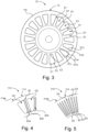
- Said arrangement O1, S1 comprises a plurality of openings O1 distributed on said end wall portion 14 so as to reduce appearance of eddy currents associated with said end wall portion 14 during operation of said electric machine.
- Fig. 3, fig. 4 and fig. 5 illustrates plan views of different embodiments of such distributed openings.
- Said openings O1 are according to an aspect of the present disclosure through holes running through said end wall portion 14. Said openings O1 are running through said end wall portion 14 from the side of the exterior surface 14a to and through the side of the interior surface 14b of the end wall portion 14.
- Said openings O1 may be distributed circumferentially of said end wall portion 14.
- the openings O1 are distributed and configured so that they efficiently break circuits for eddy currents on the end wall portion 14.
- the stator winding 22 is arranged to extend axially from end portions 20c, 20d of the stator, turned outside of the end portions and reintroduced through the end portions 20c, 20d, whereby said extending portion of the stator winding forms a so called coil ends constituting said first and second ends 22a, 22b of the stator 20.
- the electrically conductive wires of the stator 20 is according to a variant arranged to run axially in slots or apertures of said stator plates, whereby the different wire segments are arranged to be guided out from the end portions of the stator 20 from a slot or aperture of the stator plates and back into a different slot or aperture of the stator plates.
Landscapes
- Engineering & Computer Science (AREA)
- Power Engineering (AREA)
- Iron Core Of Rotating Electric Machines (AREA)
- Electric Propulsion And Braking For Vehicles (AREA)
- Synchronous Machinery (AREA)
- Connection Of Motors, Electrical Generators, Mechanical Devices, And The Like (AREA)
Description
- The present invention relates to an outer rotor electric machine. The present invention also relates to a platform, e.g. e motor vehicle, having an outer rotor electric machine.
- An electric machine comprises a rotor and a stator. A type of electric machine is an outer rotor electric machine where at least a portion of the stator is surrounded by the rotor.
- The windings and magnets of an electric machine create eddy currents in adjacent magnetically conductive materials. The eddy currents cause heat to build up in the electric machine, lowers efficiency and increase the cooling requirements. This is referred to as eddy current losses. A problem with an outer rotor electric machine is that a non-moving electric winding causes eddy current problems in an adjacent rotating surface. The electric load together with the electric frequency provided is what changes the magnetic field.
-
US2007252465A1 discloses an outer rotor electric machine and addresses the problem of eddy current losses of such an outer rotor electric machine. - It is desired to efficiently reduce eddy current losses of such electric machines.
-
CH213321A -
US9391489B2 -
JP403086051A -
US7696658B2 discloses a magnet generator including a bowl-shaped flywheel which is formed of a cylindrical portion and a bottom portion on one end side of the cylindrical portion, a plurality of magnets which are arranged on the inner peripheral surface of the cylindrical portion of the flywheel, and a power generation coil which generates power under an electromagnetic induction action with the magnets and which is disposed in opposition to the magnets within the flywheel, wherein the flywheel has a plurality of vent holes in its bottom portion and the hole base part of the vent holes is formed in a droop or curved shape for enhancing cooling efficiency. -
US20020145348A1 discloses rotor for rotating an electric machine configured to increase the stiffness without increasing the weight and to promote the flow of coolant across the rotor. Stiffening ribs and flow openings in an intermediate portion of the rotor are utilized in an intermediate portion of the rotor that interconnects the cylindrical portion that carries the permanent magnets and the hub section. - An object of the present invention is to provide an outer rotor electric machine comprising an arrangement for reducing eddy current losses of the outer rotor electric machine which is efficient and facilitates providing a compact electric machine.
- Another object of the present invention is to provide a platform comprising such an outer rotor electric machine.
- These and other objects, apparent from the following description, are achieved by an outer rotor electric machine and a platform, as set out in the appended independent claims. Preferred embodiments of the outer rotor electric machine and platform are defined in appended dependent claims.
- According to the invention the objects are achieved by an outer rotor electric machine as defined in
independent claim 1. - By thus distributing a plurality of opening on the flywheel portion so that eddy currents are reduced a very compact electric machine with high efficiency may be obtained in that the stator may be arranged close to the wheel like rotor wall portion. Thus, hereby a compact outer rotor machine may be provided without being negatively affected by eddy current losses.
- According to an embodiment of the outer rotor electric machine said openings are distributed circumferentially of said flywheel portion. By thus distributing said openings circumferentially of the flywheel portion efficient reduction of appearance of eddy currents is facilitated in that such distributed openings efficiently breaks circuits for eddy currents.
- According to an embodiment of the outer rotor electric machine said openings are obtained by a number of radially running spokes distributed around said flywheel portion. Radially running spokes provides a robust wheel like rotor wall portion with openings there between for efficient reduction of eddy currents.
- According to an embodiment of the outer rotor electric machine said openings are slots running radially on said flywheel portion. Radially running slots provides efficient reduction of eddy currents and may be particularly efficient for reducing eddy currents when the electric machine is operated at high frequencies.
- According to an embodiment of the outer rotor electric machine said openings have a circular sector configuration. Openings having a circular sector configuration provide a robust wheel like rotor wall portion with openings there between for efficient reduction of eddy currents.
- According to an embodiment of the outer rotor electric machine said circular sector configuration of said plurality of openings have rounded corners. By thus providing rounded corners of said circular sector configuration of said plurality of openings the risk of cracks occurring are in connection to the openings is reduced, wherein a robust wheel like rotor wall portion is obtained.
- According to an embodiment of the outer rotor electric machine said radially running spokes distributed around said flywheel portion comprise a sloped radially running surface creating a portion with an increased distance to said rotor. By thus providing a sloped radially running surface creating a portion with an increased distance to said rotor an even more compact electric machine is facilitated in that the stator may be arranged close to the rotor flywheel portion and still obtaining the reduction of appearance of eddy currents at the flywheel portion of the rotor.
- As stated in
independent claim 1, the outer rotor electric machine comprises a flywheel portion. Hereby a very compact arrangement may be obtained when using an internal combustion engine for rotation of said rotor in that the flywheel portion of the rotor is utilized as the flywheel of the internal combustion engine so that the crankshaft of the internal combustion engine is directly connected to the flywheel portion of the rotor, thus not requiring any coupling or internal combustion engine flywheel in that the flywheel portion of the rotor will provide the flywheel function. - According to an embodiment the outer rotor electric machine is a flywheel electric machine.
- According to an embodiment the outer rotor electric machine comprises a housing configuration comprising a stator support portion for supporting said stator. The stator support portion is according to an embodiment centrally arranged of the housing. The stator support portion may alternatively be arranged non-centrally of the housing, i.e. with a certain displacement, e.g. for facilitating an oil sump of the housing. The housing may according to an embodiment have a ring shaped cross section where the support portion of the housing may be centrally arranged or non-centrally arranged. The stator support portion is centrally arranged relative to the stator.
- According to the invention the objects are achieved by a platform comprising an outer rotor electric machine as set out herein.
- According to an embodiment the platform comprises a vehicle.
- For a better understanding of the present invention reference is made to the following detailed description when read in conjunction with the accompanying drawings, wherein like reference characters refer to like parts throughout the several views, and in which:
-
Fig. 1 schematically illustrates a platform according to an embodiment of the present invention; -
Fig. 2 schematically illustrates a cross section view of an outer rotor electric machine comprising an arrangement for reducing eddy current losses of the electric machine according to an embodiment of the present invention; -
Fig. 3 schematically illustrates a plan view of a rotor for an outer rotor electric machine according tofig. 2 , said rotor comprising an arrangement for reducing eddy current losses according to an embodiment of the present invention; -
Fig. 4 schematically illustrates a portion of a rotor for an outer rotor electric machine according tofig. 2 , said rotor comprising an arrangement for reducing eddy current losses according to an embodiment of the present invention; and -
Fig. 5 schematically illustrates a portion of a rotor for an outer rotor electric machine according tofig. 2 , said rotor comprising an arrangement for reducing eddy current losses according to an embodiment of the present invention. - With reference to
fig. 1 a platform P is shown, wherein the platform P is comprised in a group comprising motor vehicles such as military vehicles, utility vehicles, automobiles, boat, helicopter or similar, a power station, any electrically driven machine or similar device wherein the device comprises an electric machine for operation thereof. The platform P comprises at least one electric machine I comprising an arrangement for reducing eddy current losses of the electric machine I according to the present invention. - According to an embodiment in which the electric machine is comprised in a motor vehicle the electric machine is configured for propulsion of said motor vehicle, which thereby comprises an electrically driven motor vehicle. The arrangement for reducing eddy current losses of the electric machine may be configured according to any of the below described embodiments.
-
Fig. 2 schematically illustrates a cross section view of an outer rotor electric machine I comprising an arrangement O1, S1 for reducing eddy current losses of the electric machine according to an embodiment of the present invention. - The electric machine I is thus of outer rotor type. The outer rotor electric machine I may be any type of outer rotor electric machine with a rotatably arranged rotor and a stator. The electric machine I in
fig. 2 comprises a rotatably arrangedrotor 10 and astator 20 provided withwindings 22. - By electric machine I of outer rotor type, i.e. outer rotor electric machine I, is meant an electric machine I wherein the
rotor 10 or portion of the rotor is arranged to enclose thestator 20 or part of thestator 20. - The
rotor 10 comprises anouter rotor portion 12 arranged to surround thestator 20 or part of thestator 20. Theouter rotor portion 12 has an essentially tubular configuration. Theouter rotor portion 12 has anexterior surface 12a andinterior surface 12b opposite to theexterior surface 12a. Theouter rotor portion 12 may comprisemagnets 12c. - The
rotor 10 further comprises a wheel likeend wall portion 14. The wheel likeend wall portion 14 may, according to an embodiment, be constituted by a flywheel portion. Theend wall portion 14 has anexterior surface 14a andinterior surface 14b opposite to theexterior surface 12a. The wheel likeend wall portion 14 has a circumferentialouter surface 14c. - The
stator 20 has an essentially tubular configuration. The stator comprisesstator windings 22. Thestator 20 has anexterior surface 20a andinterior surface 20b opposite to theexterior surface 20a. Thestator 20 has afirst end 22a arranged to face saidend wall portion 14 of therotor 10 and an oppositesecond end 22b. Thefirst end 22a of thestator 20 is thus arranged to face theinterior surface 14b of theend wall portion 14 of therotor 10. - The
rotor 10 comprises an arrangement O1, S1 for reducing eddy current losses. Said arrangement O1, S1 comprises a plurality of openings O1 distributed on saidend wall portion 14 so as to reduce appearance of eddy currents associated with saidend wall portion 14 during operation of said electric machine.Fig. 3, fig. 4 and fig. 5 illustrates plan views of different embodiments of such distributed openings. By thus distributing a plurality of openings O1 on theend wall portion 14 so that eddy currents are reduced a very compact electric machine I with high efficiency is obtained in that thestator 20 may be arranged close to the wheel likerotor wall portion 14 as shown infig. 2 . - Said openings O1 are according to an aspect of the present disclosure through holes running through said
end wall portion 14. Said openings O1 are running through saidend wall portion 14 from the side of theexterior surface 14a to and through the side of theinterior surface 14b of theend wall portion 14. - Said openings O1 may be distributed circumferentially of said
end wall portion 14. The openings O1 are distributed and configured so that they efficiently break circuits for eddy currents on theend wall portion 14. - Said openings may be obtained by a number of radially running spokes S1, see e.g.
fig. 3 , distributed around said wheel likeend wall portion 14. The radially running spokes are arranged to be distributed around said wheel likeend wall portion 14 so that said openings O1 are obtained there between. The arrangement O1, S1 comprises according to an aspect of the present disclosure said spokes S1. - The
stator 20 is according to a variant constructed from stacked stator plates (not shown). Thestator windings 22 according to a variant comprises a set of electrically conductive wires/conductors, preferably copper wires, through which a current is arranged to be conducted for operating the electric machine I. Said wires may be of different thickness. Saidstator windings 22 are arranged to run axially so that the winding is adjacently near therotor 10. The stator winding 22 is arranged to extend axially fromend portions end portions second ends stator 20. - The electrically conductive wires of the
stator 20 is according to a variant arranged to run axially in slots or apertures of said stator plates, whereby the different wire segments are arranged to be guided out from the end portions of thestator 20 from a slot or aperture of the stator plates and back into a different slot or aperture of the stator plates. - The
interior surface 12b of theouter rotor portion 12 is arranged nearby and separated from theexterior surface 20a of thestator 20. Therotor 10 is arranged concentrically relative to thestator 20. - The electric machine I comprises or is attached to a
housing configuration 30. Thehousing configuration 30 is arranged to house at least part of therotor 10 andstator 20. - The
housing configuration 30 comprises anouter wall portion 32. Theouter wall portion 32 has anexterior surface 32a and aninterior surface 32b. Theouter wall portion 32 has an essentially tubular configuration. Theouter wall portion 32 of thehousing configuration 30 is arranged to surround at least parts of therotor 10 andstator 20. - The
housing configuration 30 comprises a housingend wall portion 34. The housingend wall portion 34 has anexterior surface 34a and aninterior surface 34b. Theinterior surface 34b of the housingend wall portion 34 is arranged to face the second end 22d of thestator 20 and therotor 10, i.e. end portions of theouter rotor portion 12 of therotor 10. - The
housing configuration 30 comprises astator support portion 36 for supporting saidstator 20. Thestator support portion 36 is according to this embodiment centrally arranged of thehousing 30. Thestator support portion 36 is centrally arranged relative to thestator 20. The centrally arrangedstator support portion 36 has anexterior surface 36a facing theinterior surface 20b of thestator 20. The centrally arrangedstator support portion 36 has anexterior surface 36a being attached to saidstator 20 for supporting saidstator 20. - The stator support portion may alternatively be arranged non-centrally of the housing, i.e. with a certain displacement, e.g. for facilitating an oil sump of the housing. The
housing 30 may according to an embodiment have an essentially ring shaped configuration, i.e.exterior surface 32a, where the support portion of the housing is centrally arranged as infig. 2 , or alternatively non-centrally arranged. - Said
rotor 10 is intended to be attached to an axle. Therotor 10 may be attached to a drive shaft and is thus arranged to rotate the drive shaft or arranged to be rotated by the drive shaft. Therotor 10 is configured to be rotated about an axis X. - According to an embodiment of the arrangement said
end wall portion 14 of therotor 10 constitutes aflywheel portion 14. - In the embodiment shown in
fig. 2 the electric machine I is operably connected to aninternal combustion engine 40. A portion of saidinternal combustion engine 40 is illustrated with dotted lines infig. 2 . Theinternal combustion engine 40 is according to an embodiment a diesel engine. - The
internal combustion engine 40 has acrankshaft 42 which is journaled inbearings 50. Thecrankshaft 42 of the internal combustion engine is attached to theflywheel portion 14 of therotor 10. Thecombustion engine 40 may be arranged to drive the electric machine I by means of thecrankshaft 42 connected to theflywheel 14 of the rotor of the electric machine I, wherein the electric machine will operate as a generator. In such an embodiment the electric machine I is operating as a flywheel generator. - When thus using e.g. an
internal combustion engine 40 for rotation of saidrotor 10 by using theflywheel portion 14 of therotor 10 as the flywheel of the internal combustion engine so that the crankshaft of the internal combustion engine is directly connected to theflywheel portion 14 of the rotor a compact device is obtained, thus not requiring any coupling or internal combustion engine flywheel. Thus the rotor will provide the flywheel function. - The outer rotor electric machine I according to the present invention may also be used as an electric starter motor used to rotate the
internal combustion engine 40 by rotating thecrankshaft 42 so as to initiate the operation of theengine 40. - Above an outer rotor electric machine I is a flywheel electric machine. The outer rotor electric machine according to the present invention may be any suitable outer rotor electric machine having a rotor comprising any kind of end wall portion plurality of openings distributed on the end wall portion so as to reduce appearance of eddy currents associated with said end wall portion during operation of said electric machine. The end wall portion thus does not need to be configured as a flywheel.
- The outer rotor electric machine according to the present invention may be any suitable outer rotor electric machine for any suitable operation. The outer rotor electric machine according to the present invention may be any suitable outer rotor electric machine and may be configured to operate as a generator or an electric motor.
Fig. 3 schematically illustrates a plan view of arotor 10 for an electric machine according tofig. 2 . - The
rotor 10 may be the rotor according tofig. 2 . Therotor 10 thus comprises theend wall portion 14. Therotor 10 comprises an arrangement O1, S1 for reducing eddy current losses according to an embodiment of the present invention. - Said arrangement comprises a plurality of openings O1 distributed on said
end wall portion 14 so as to reduce appearance of eddy currents associated with saidend wall portion 14 during operation of said electric machine. By thus distributing a plurality of openings O1 on theend wall portion 14 so that eddy currents are reduced a very compact electric machine I with high efficiency may be obtained in that thestator 20 may be arranged close to the wheel likerotor wall portion 14 as shown infig. 2 . Said openings O1 are according to an aspect of the present disclosure through holes running through saidend wall portion 14. Said openings O1 are thus according to an aspect of the present disclosure running through saidend wall portion 14 as described and illustrated infig. 2 . - According to this embodiment of the arrangement O1, S1 said openings are distributed circumferentially of said
end wall portion 14. The openings O1 are distributed and configured so that they efficiently break circuits for eddy currents on theend wall portion 14. - Said openings are obtained by a number of radially running spokes S1 distributed around said wheel like
end wall portion 14. The radially running spokes S1 are distributed around said wheel likeend wall portion 14 so that said openings O1 are obtained there between. Radially running spokes provides a robust wheel likerotor wall portion 14 with openings O1 there between for efficient reduction of eddy currents. - According to this embodiment of the arrangement O1, S1 said openings O1 have a circular sector configuration. The openings O1 thus have an essentially triangular configuration. Openings O1 having a circular sector configuration provide a robust wheel like
rotor wall portion 14 with openings there between for efficient reduction of eddy currents. - The openings O1 have a base end O1a facing the outer circumference of the wheel like
rotor wall portion 14, a pointier opposite end O1b facing the centre of thewall portion 14 and sides O1c, O1d - According to an embodiment of the arrangement said circular sector configuration of said plurality of openings O1 have rounded corners C1, C2, C3. By thus providing rounded corners C1, C2, C3of said circular sector configuration of said plurality of openings O1 the risk of cracks occurring are in connection to the openings O1 is reduced, wherein a robust wheel like
rotor wall portion 14 is obtained. - According to an embodiment of the arrangement said
end wall portion 14 constitutes aflywheel portion 14. -
Fig. 4 schematically illustrates a portion of arotor 110 for an outer rotor electric machine. -
Said rotor 110 comprises an arrangement O2, S2 for reducing eddy current losses according to an embodiment of the present invention. Therotor 110 may be applied to an outer rotor electric machine according tofig. 2 . - The
rotor 110 comprises anend wall portion 114. Therotor 110 comprises an arrangement O2, S2 for reducing eddy current losses according to an embodiment of the present invention. - Said arrangement comprises a plurality of openings O2 distributed on said
end wall portion 114 so as to reduce appearance of eddy currents associated with saidend wall portion 114 during operation of said electric machine. By thus distributing a plurality of openings O2 on theend wall portion 114 so that eddy currents are reduced a very compact outer rotor electric machine with high efficiency may be obtained in that the stator may be arranged close to the wheel like rotor wall portion as shown infig. 2 . Said openings O2 are according to an aspect of the present disclosure through holes running through saidend wall portion 114. Said openings O2 are according to an aspect of the present disclosure running through saidend wall portion 114. - According to this embodiment of the arrangement O2, S2 said openings O2 are distributed circumferentially of said
end wall portion 114. The openings O2 are distributed and configured so that they efficiently break circuits for eddy currents on theend wall portion 114. - Said openings are obtained by a number of radially running spokes S2 distributed around said wheel like
end wall portion 114. The radially running spokes S2 are distributed around said wheel likeend wall portion 114 so that said openings O2 are obtained there between. Radially running spokes provides a robust wheel likerotor wall portion 114 with openings O2 there between for efficient reduction of eddy currents. The arrangement O2, S2 comprises according to an aspect of the present disclosure said spokes S2. - According to this embodiment of the arrangement O2, S2 said openings O2 have a circular sector configuration. The openings O2 thus have an essentially triangular configuration. Openings O2 having a circular sector configuration provide a robust wheel like
rotor wall portion 114 with openings there between for efficient reduction of eddy currents. - According to this embodiment of the arrangement O2, S2 said radially running spokes S2 distributed around said
end wall portion 114 comprise a sloped radially running surface S2a creating a portion with an increased distance to said rotor. Said radially running spokes S2 distributed around saidend wall portion 114 comprise a non-sloped radially running surface S2b. - The embodiment of the arrangement O2, S2 according to
fig. 4 differs from the embodiment of the arrangement O1, S1 according tofig. 3 essentially by said sloped radially running surface S2a of the radially running spokes S2. By thus providing a sloped radially running surface creating a portion with an increased distance to said rotor an even more compact electric machine is facilitated in that the stator may be arranged close to the rotor end wall portion and still obtaining the reduction of appearance of eddy currents at the end wall portion of the rotor. -
Fig. 5 schematically illustrates a portion of a rotor for an electric machine according tofig. 2 -
Said rotor 210 comprises an arrangement O3, S3 for reducing eddy current losses according to an embodiment of the present invention. Therotor 210 may be applied to an electric machine according tofig. 2 . - The
rotor 210 comprises anend wall portion 214. Therotor 210 comprises an arrangement O3, S3 for reducing eddy current losses according to an embodiment of the present invention. - Said arrangement O3, S3 comprises a plurality of openings O3 distributed on said
end wall portion 214 so as to reduce appearance of eddy currents associated with saidend wall portion 214 during operation of said electric machine. By thus distributing a plurality of openings O3 on theend wall portion 214 so that eddy currents are reduced a very compact outer rotor electric machine with high efficiency may be obtained in that the stator may be arranged close to the wheel like rotor wall portion as shown infig. 2 . Said openings O3 are according to an aspect of the present disclosure through holes running through saidend wall portion 214. Said openings O3 are according to an aspect of the present disclosure running through saidend wall portion 214. - According to this embodiment of the arrangement O3, S3 said openings are distributed circumferentially of said
end wall portion 214. The openings O3 are distributed and configured so that they efficiently break circuits for eddy currents on theend wall portion 214. - Said openings are obtained by a number of radially running spokes S3 distributed around said wheel like
end wall portion 214. The radially running spokes S3 are distributed around said wheel likeend wall portion 214 so that said openings O3 are obtained there between. Radially running spokes provides a robust wheel likerotor wall portion 214 with openings O3 there between for efficient reduction of eddy currents. The arrangement O3, S3 comprises according to an aspect of the present disclosure said spokes S3. - According to this embodiment of the arrangement said openings O3 are slots running radially on said flywheel portion.
- The embodiment of the arrangement O3, S3 according to
fig. 5 differs from the embodiment of the arrangement O1, S1 according tofig. 3 essentially by the slot shape of the openings O3 and thus the configuration of the spokes S3 in order to provide said radially running slots O3. According to an embodiment the radially running slots are provided by providing relatively thin radially running spokes distributed around the wheel likeend wall portion 214 relatively close to each other. Such radially running slots O3 provides efficient reduction of eddy currents and may be particularly efficient for reducing eddy currents when the electric machine is operated at high frequencies. The efficiency of reduction of eddy currents increases with the number of radially running slots O3. Slots O3 facilitates providing a greater number of openings radially distributed around the wheel likeend wall portion 214. - Above, with reference to
fig. 3-5 , different embodiments of pluralities of openings O1; O2; O3 distributed on saidend wall portion 14; 114; 214 so as to reduce appearance of eddy currents associated with saidend wall portion 14; 114; 214 during operation of said electric machine have been described. The openings distributed on said end wall portion may have any suitable configuration and may be distributed in any suitable way. The openings distributed on said end wall portion may thus alternatively have an irregular shape and/or may be distributed irregularly on said end wall portion. - The foregoing description of the preferred embodiments of the present invention has been provided for the purposes of illustration and description. It is not intended to be exhaustive or to limit the invention to the precise forms disclosed. Obviously, many modifications and variations will be apparent to practitioners skilled in the art. The embodiments were chosen and described in order to best explain the principles of the invention and its practical applications, thereby enabling others skilled in the art to understand the invention for various embodiments and with the various modifications suited to the particular use contemplated.
Claims (11)
- An outer rotor electric machine (I), said electric machine (I) comprising a rotatably arranged rotor (10; 110; 210) and a stator (20) comprising windings (22) comprising opposite coil ends (22a, 22b) at axially opposing sides of the stator (20), said rotor comprising an outer rotor portion (12) surrounding said stator (20) or part of said stator and a flywheel portion (14; 114; 214), wherein one of said coil ends (22a) of said stator (20) is arranged to face said flywheel portion (14; 114; 214), wherein said electric machine (I) is associated with a combustion engine (40) for driving said rotor, said flywheel portion of said rotor constituting a flywheel for said combustion engine (40), said internal combustion engine (40) comprising a crankshaft (42) directly connected to said flywheel portion of the rotor, said flywheel portion (14; 114; 214) being of electro-magnetically conductive material, wherein, during operation of said outer rotor electric machine, the magnetic field generated by the winding coils changes when excited by a variable frequency current, wherein said nonrotating stator windings causes eddy currents in the rotating flywheel portion, said eddy currents causing thermal losses in the electric machine (I), said electric machine comprising an arrangement (O1, S1; O2, S2; O3, S3) configured to reduce such eddy current caused thermal losses of the outer rotor electric machine (I), said arrangement comprising a plurality of openings (O1; O2; O3) distributed on said flywheel portion (14; 114; 214) so that said coil end (22a) facing said flywheel portion faces said openings (O1; O2; O3) so as to reduce appearance of said eddy currents associated with said flywheel portion (14; 114; 214) during operation of said electric machine (I).
- The outer rotor electric machine according to claim 1, wherein said openings (O1; O2; O3) are distributed circumferentially of said flywheel portion (14; 114; 214).
- The outer rotor electric machine according to claim 1 or 2, wherein said openings (O1; O2; O3) are obtained by a number of radially running spokes (S1; S2; S3) distributed around said flywheel portion (14; 114; 214).
- The outer rotor electric machine according to any of claims 1-3, wherein said openings (S3) are slots (S3) running radially on said flywheel portion (214).
- The outer rotor electric machine according to any of claims 1-3, wherein said openings (O1; O2) have a circular sector configuration.
- The outer rotor electric machine according to claim 5, wherein said circular sector configuration of said plurality of openings (O1; O2) have rounded corners (C1, C2, C3).
- The outer rotor electric machine according to any of claims 1-6, wherein said radially running spokes (S2) distributed around said flywheel portion (114) comprise a sloped radially running surface (S2a) creating a portion with an increased distance to said rotor (20).
- The outer rotor electric machine according to any of claims 1-7, wherein said electric machine (I) is a flywheel electric machine.
- The outer rotor electric machine according to any of claims 1-8, wherein said electric machine (I) comprises a housing configuration (30) comprising a stator support portion (36) for supporting said stator (20).
- A platform (P) comprising an outer rotor electric machine (I) according to any of claims 1-9.
- A platform according to claim 10, comprising a vehicle.
Priority Applications (1)
| Application Number | Priority Date | Filing Date | Title |
|---|---|---|---|
| RS20240892A RS65846B1 (en) | 2018-03-23 | 2019-03-19 | Outer rotor electric machine |
Applications Claiming Priority (2)
| Application Number | Priority Date | Filing Date | Title |
|---|---|---|---|
| SE1850329A SE542930C2 (en) | 2018-03-23 | 2018-03-23 | Arrangement for reducing eddy current losses of an outer rotor electric machine |
| PCT/SE2019/050249 WO2019182503A1 (en) | 2018-03-23 | 2019-03-19 | Arrangement for reducing eddy current losses of an outer rotor electric machine |
Publications (4)
| Publication Number | Publication Date |
|---|---|
| EP3769407A1 EP3769407A1 (en) | 2021-01-27 |
| EP3769407A4 EP3769407A4 (en) | 2021-12-15 |
| EP3769407B1 true EP3769407B1 (en) | 2024-07-03 |
| EP3769407C0 EP3769407C0 (en) | 2024-07-03 |
Family
ID=67987476
Family Applications (1)
| Application Number | Title | Priority Date | Filing Date |
|---|---|---|---|
| EP19771587.3A Active EP3769407B1 (en) | 2018-03-23 | 2019-03-19 | Outer rotor electric machine |
Country Status (10)
| Country | Link |
|---|---|
| US (1) | US11575287B2 (en) |
| EP (1) | EP3769407B1 (en) |
| KR (1) | KR102661970B1 (en) |
| ES (1) | ES2983316T3 (en) |
| HU (1) | HUE068109T2 (en) |
| IL (1) | IL277345B2 (en) |
| PL (1) | PL3769407T3 (en) |
| RS (1) | RS65846B1 (en) |
| SE (1) | SE542930C2 (en) |
| WO (1) | WO2019182503A1 (en) |
Families Citing this family (1)
| Publication number | Priority date | Publication date | Assignee | Title |
|---|---|---|---|---|
| WO2019240883A1 (en) * | 2018-06-14 | 2019-12-19 | American Axle & Manufacturing, Inc. | Hybrid axle assembly having inside out motor and ring gear directly supported on an axle housing |
Family Cites Families (10)
| Publication number | Priority date | Publication date | Assignee | Title |
|---|---|---|---|---|
| CH213321A (en) * | 1939-05-11 | 1941-01-31 | Bosch Gmbh Robert | Magnetic flywheel. |
| US4205247A (en) * | 1978-03-15 | 1980-05-27 | General Electric Company | Prime mover and methods |
| JPH0386051A (en) * | 1989-08-29 | 1991-04-11 | Canon Electron Inc | Yoke for motor |
| JP2002315245A (en) * | 2001-04-09 | 2002-10-25 | Moric Co Ltd | Permanent magnet generator rotor |
| US7608964B2 (en) * | 2004-03-31 | 2009-10-27 | Daikin Industries, Ltd. | Motor, blower, compressor, and air conditioner |
| JP2007295768A (en) * | 2006-04-27 | 2007-11-08 | Kokusan Denki Co Ltd | Outer rotor type magnet generator |
| JP2008154391A (en) * | 2006-12-19 | 2008-07-03 | Mitsubishi Electric Corp | Magnet generator |
| GB201019473D0 (en) * | 2010-11-17 | 2010-12-29 | Ricardo Uk Ltd | An improved coupler |
| JP6286170B2 (en) * | 2013-09-27 | 2018-02-28 | 株式会社ミツバ | Hub dynamo |
| CN105471127B (en) * | 2014-05-29 | 2019-02-05 | 德昌电机(深圳)有限公司 | Motor and motor magnetic core |
-
2018
- 2018-03-23 SE SE1850329A patent/SE542930C2/en unknown
-
2019
- 2019-03-19 ES ES19771587T patent/ES2983316T3/en active Active
- 2019-03-19 WO PCT/SE2019/050249 patent/WO2019182503A1/en not_active Ceased
- 2019-03-19 US US16/975,028 patent/US11575287B2/en active Active
- 2019-03-19 RS RS20240892A patent/RS65846B1/en unknown
- 2019-03-19 EP EP19771587.3A patent/EP3769407B1/en active Active
- 2019-03-19 KR KR1020207024497A patent/KR102661970B1/en active Active
- 2019-03-19 HU HUE19771587A patent/HUE068109T2/en unknown
- 2019-03-19 PL PL19771587.3T patent/PL3769407T3/en unknown
-
2020
- 2020-09-14 IL IL277345A patent/IL277345B2/en unknown
Also Published As
| Publication number | Publication date |
|---|---|
| IL277345B1 (en) | 2023-04-01 |
| HUE068109T2 (en) | 2024-12-28 |
| US20210006113A1 (en) | 2021-01-07 |
| US11575287B2 (en) | 2023-02-07 |
| WO2019182503A1 (en) | 2019-09-26 |
| PL3769407T3 (en) | 2024-10-21 |
| SE1850329A1 (en) | 2019-09-24 |
| SE542930C2 (en) | 2020-09-15 |
| EP3769407C0 (en) | 2024-07-03 |
| IL277345B2 (en) | 2023-08-01 |
| KR20200135311A (en) | 2020-12-02 |
| EP3769407A4 (en) | 2021-12-15 |
| IL277345A (en) | 2020-10-29 |
| ES2983316T3 (en) | 2024-10-22 |
| KR102661970B1 (en) | 2024-04-26 |
| EP3769407A1 (en) | 2021-01-27 |
| RS65846B1 (en) | 2024-09-30 |
Similar Documents
| Publication | Publication Date | Title |
|---|---|---|
| US6046518A (en) | Axial gap electrical machine | |
| US6404097B1 (en) | Rotary electrical machines | |
| KR101440624B1 (en) | Electric devices and rotors | |
| CN100405710C (en) | rotating electrical machine | |
| US9385567B2 (en) | Rotating electric machine | |
| WO2012019943A2 (en) | A dynamo-electric machine | |
| CN115398774B (en) | Stator for electric axial flux machine and electric axial flux machine | |
| US20230051582A1 (en) | Rotor, method for producing a rotor and axial flux machine | |
| US20050146234A1 (en) | Magneto generator | |
| CN107891739B (en) | Segmented switched reluctance motors for powertrain electrification | |
| GB2338117A (en) | Variable axial airgap rotary electric machines | |
| US11575287B2 (en) | Arrangement for reducing eddy current losses of an outer rotor electric machine | |
| CN104247232B (en) | motor | |
| CN211557003U (en) | Axial magnetic field motor | |
| US20250149939A1 (en) | Rotor for a permanent magnet electric machine | |
| CN1276645A (en) | Disk-type permanent-magnet electric machine with stepless speed regulation | |
| JP4556408B2 (en) | Claw pole type rotating machine | |
| EP3806288B1 (en) | Driving motor | |
| KR20230084855A (en) | Afpm motor with rfpm motor structure applied | |
| US20080067883A1 (en) | Generator and/or motor assembly | |
| CN219554800U (en) | Induction motor | |
| US20250330072A1 (en) | Permanent magnet electric machine and method of field weakening in a permanent magnet electric machine | |
| JP2024093358A (en) | Axial gap type rotating electric machine and drone | |
| CN119298462A (en) | For surface/internal permanent magnet rotors of electric motors | |
| US20220077729A1 (en) | Stator tooth for a stator of an electric machine |
Legal Events
| Date | Code | Title | Description |
|---|---|---|---|
| STAA | Information on the status of an ep patent application or granted ep patent |
Free format text: STATUS: THE INTERNATIONAL PUBLICATION HAS BEEN MADE |
|
| PUAI | Public reference made under article 153(3) epc to a published international application that has entered the european phase |
Free format text: ORIGINAL CODE: 0009012 |
|
| STAA | Information on the status of an ep patent application or granted ep patent |
Free format text: STATUS: REQUEST FOR EXAMINATION WAS MADE |
|
| 17P | Request for examination filed |
Effective date: 20200916 |
|
| AK | Designated contracting states |
Kind code of ref document: A1 Designated state(s): AL AT BE BG CH CY CZ DE DK EE ES FI FR GB GR HR HU IE IS IT LI LT LU LV MC MK MT NL NO PL PT RO RS SE SI SK SM TR |
|
| AX | Request for extension of the european patent |
Extension state: BA ME |
|
| DAV | Request for validation of the european patent (deleted) | ||
| DAX | Request for extension of the european patent (deleted) | ||
| REG | Reference to a national code |
Ref legal event code: R079 Ipc: H02K0001270000 Ref country code: DE Ref legal event code: R079 Ref document number: 602019054629 Country of ref document: DE Free format text: PREVIOUS MAIN CLASS: H02K0021220000 Ipc: H02K0001270000 |
|
| A4 | Supplementary search report drawn up and despatched |
Effective date: 20211116 |
|
| RIC1 | Information provided on ipc code assigned before grant |
Ipc: H02K 7/18 20060101ALN20211110BHEP Ipc: H02K 7/14 20060101ALN20211110BHEP Ipc: H02K 7/00 20060101ALN20211110BHEP Ipc: H02K 9/06 20060101ALN20211110BHEP Ipc: H02K 1/30 20060101ALN20211110BHEP Ipc: H02K 21/22 20060101ALI20211110BHEP Ipc: H02K 1/27 20060101AFI20211110BHEP |
|
| STAA | Information on the status of an ep patent application or granted ep patent |
Free format text: STATUS: EXAMINATION IS IN PROGRESS |
|
| 17Q | First examination report despatched |
Effective date: 20230519 |
|
| GRAP | Despatch of communication of intention to grant a patent |
Free format text: ORIGINAL CODE: EPIDOSNIGR1 |
|
| STAA | Information on the status of an ep patent application or granted ep patent |
Free format text: STATUS: GRANT OF PATENT IS INTENDED |
|
| RIC1 | Information provided on ipc code assigned before grant |
Ipc: H02K 1/2791 20220101ALN20240229BHEP Ipc: H02K 7/18 20060101ALN20240229BHEP Ipc: H02K 7/14 20060101ALN20240229BHEP Ipc: H02K 7/00 20060101ALN20240229BHEP Ipc: H02K 9/06 20060101ALN20240229BHEP Ipc: H02K 1/30 20060101ALN20240229BHEP Ipc: H02K 21/22 20060101ALI20240229BHEP Ipc: H02K 1/27 20060101AFI20240229BHEP |
|
| INTG | Intention to grant announced |
Effective date: 20240315 |
|
| GRAS | Grant fee paid |
Free format text: ORIGINAL CODE: EPIDOSNIGR3 |
|
| GRAA | (expected) grant |
Free format text: ORIGINAL CODE: 0009210 |
|
| STAA | Information on the status of an ep patent application or granted ep patent |
Free format text: STATUS: THE PATENT HAS BEEN GRANTED |
|
| AK | Designated contracting states |
Kind code of ref document: B1 Designated state(s): AL AT BE BG CH CY CZ DE DK EE ES FI FR GB GR HR HU IE IS IT LI LT LU LV MC MK MT NL NO PL PT RO RS SE SI SK SM TR |
|
| REG | Reference to a national code |
Ref country code: CH Ref legal event code: EP |
|
| REG | Reference to a national code |
Ref country code: DE Ref legal event code: R096 Ref document number: 602019054629 Country of ref document: DE |
|
| U01 | Request for unitary effect filed |
Effective date: 20240703 |
|
| U07 | Unitary effect registered |
Designated state(s): AT BE BG DE DK EE FI FR IT LT LU LV MT NL PT SE SI Effective date: 20240712 |
|
| REG | Reference to a national code |
Ref country code: ES Ref legal event code: FG2A Ref document number: 2983316 Country of ref document: ES Kind code of ref document: T3 Effective date: 20241022 |
|
| REG | Reference to a national code |
Ref country code: SK Ref legal event code: T3 Ref document number: E 44933 Country of ref document: SK |
|
| REG | Reference to a national code |
Ref country code: HU Ref legal event code: AG4A Ref document number: E068109 Country of ref document: HU |
|
| PG25 | Lapsed in a contracting state [announced via postgrant information from national office to epo] |
Ref country code: GR Free format text: LAPSE BECAUSE OF FAILURE TO SUBMIT A TRANSLATION OF THE DESCRIPTION OR TO PAY THE FEE WITHIN THE PRESCRIBED TIME-LIMIT Effective date: 20241004 |
|
| PG25 | Lapsed in a contracting state [announced via postgrant information from national office to epo] |
Ref country code: IS Free format text: LAPSE BECAUSE OF FAILURE TO SUBMIT A TRANSLATION OF THE DESCRIPTION OR TO PAY THE FEE WITHIN THE PRESCRIBED TIME-LIMIT Effective date: 20241103 |
|
| PG25 | Lapsed in a contracting state [announced via postgrant information from national office to epo] |
Ref country code: HR Free format text: LAPSE BECAUSE OF FAILURE TO SUBMIT A TRANSLATION OF THE DESCRIPTION OR TO PAY THE FEE WITHIN THE PRESCRIBED TIME-LIMIT Effective date: 20240703 |
|
| PG25 | Lapsed in a contracting state [announced via postgrant information from national office to epo] |
Ref country code: IS Free format text: LAPSE BECAUSE OF FAILURE TO SUBMIT A TRANSLATION OF THE DESCRIPTION OR TO PAY THE FEE WITHIN THE PRESCRIBED TIME-LIMIT Effective date: 20241103 Ref country code: HR Free format text: LAPSE BECAUSE OF FAILURE TO SUBMIT A TRANSLATION OF THE DESCRIPTION OR TO PAY THE FEE WITHIN THE PRESCRIBED TIME-LIMIT Effective date: 20240703 Ref country code: GR Free format text: LAPSE BECAUSE OF FAILURE TO SUBMIT A TRANSLATION OF THE DESCRIPTION OR TO PAY THE FEE WITHIN THE PRESCRIBED TIME-LIMIT Effective date: 20241004 |
|
| U20 | Renewal fee for the european patent with unitary effect paid |
Year of fee payment: 7 Effective date: 20250123 |
|
| PG25 | Lapsed in a contracting state [announced via postgrant information from national office to epo] |
Ref country code: SM Free format text: LAPSE BECAUSE OF FAILURE TO SUBMIT A TRANSLATION OF THE DESCRIPTION OR TO PAY THE FEE WITHIN THE PRESCRIBED TIME-LIMIT Effective date: 20240703 |
|
| PLBE | No opposition filed within time limit |
Free format text: ORIGINAL CODE: 0009261 |
|
| STAA | Information on the status of an ep patent application or granted ep patent |
Free format text: STATUS: NO OPPOSITION FILED WITHIN TIME LIMIT |
|
| 26N | No opposition filed |
Effective date: 20250404 |
|
| PGFP | Annual fee paid to national office [announced via postgrant information from national office to epo] |
Ref country code: ES Payment date: 20250523 Year of fee payment: 7 |
|
| PG25 | Lapsed in a contracting state [announced via postgrant information from national office to epo] |
Ref country code: MC Free format text: LAPSE BECAUSE OF FAILURE TO SUBMIT A TRANSLATION OF THE DESCRIPTION OR TO PAY THE FEE WITHIN THE PRESCRIBED TIME-LIMIT Effective date: 20240703 |
|
| REG | Reference to a national code |
Ref country code: CH Ref legal event code: H13 Free format text: ST27 STATUS EVENT CODE: U-0-0-H10-H13 (AS PROVIDED BY THE NATIONAL OFFICE) Effective date: 20251023 |
|
| PG25 | Lapsed in a contracting state [announced via postgrant information from national office to epo] |
Ref country code: CH Free format text: LAPSE BECAUSE OF NON-PAYMENT OF DUE FEES Effective date: 20250331 |
|
| PG25 | Lapsed in a contracting state [announced via postgrant information from national office to epo] |
Ref country code: IE Free format text: LAPSE BECAUSE OF NON-PAYMENT OF DUE FEES Effective date: 20250319 |
|
| U20 | Renewal fee for the european patent with unitary effect paid |
Year of fee payment: 8 Effective date: 20260129 |
|
| PGFP | Annual fee paid to national office [announced via postgrant information from national office to epo] |
Ref country code: GB Payment date: 20260119 Year of fee payment: 8 |
|
| PGFP | Annual fee paid to national office [announced via postgrant information from national office to epo] |
Ref country code: NO Payment date: 20260227 Year of fee payment: 8 |
|
| PG25 | Lapsed in a contracting state [announced via postgrant information from national office to epo] |
Ref country code: RO Free format text: LAPSE BECAUSE OF FAILURE TO SUBMIT A TRANSLATION OF THE DESCRIPTION OR TO PAY THE FEE WITHIN THE PRESCRIBED TIME-LIMIT Effective date: 20240703 |
|
| PGFP | Annual fee paid to national office [announced via postgrant information from national office to epo] |
Ref country code: HU Payment date: 20260202 Year of fee payment: 8 |
|
| PGFP | Annual fee paid to national office [announced via postgrant information from national office to epo] |
Ref country code: RS Payment date: 20260302 Year of fee payment: 8 |
|
| PGFP | Annual fee paid to national office [announced via postgrant information from national office to epo] |
Ref country code: TR Payment date: 20260206 Year of fee payment: 8 |
|
| PGFP | Annual fee paid to national office [announced via postgrant information from national office to epo] |
Ref country code: CZ Payment date: 20260121 Year of fee payment: 8 |
|
| PGFP | Annual fee paid to national office [announced via postgrant information from national office to epo] |
Ref country code: PL Payment date: 20260220 Year of fee payment: 8 |
|
| PGFP | Annual fee paid to national office [announced via postgrant information from national office to epo] |
Ref country code: SK Payment date: 20260121 Year of fee payment: 8 |