EP3768959B1 - Method for managing a fuel supply of a spark ignition internal combustion engine and a supply system implementing said method - Google Patents
Method for managing a fuel supply of a spark ignition internal combustion engine and a supply system implementing said method Download PDFInfo
- Publication number
- EP3768959B1 EP3768959B1 EP19721065.1A EP19721065A EP3768959B1 EP 3768959 B1 EP3768959 B1 EP 3768959B1 EP 19721065 A EP19721065 A EP 19721065A EP 3768959 B1 EP3768959 B1 EP 3768959B1
- Authority
- EP
- European Patent Office
- Prior art keywords
- internal combustion
- combustion engine
- condition
- fuel
- catalyst
- Prior art date
- Legal status (The legal status is an assumption and is not a legal conclusion. Google has not performed a legal analysis and makes no representation as to the accuracy of the status listed.)
- Active
Links
Images
Classifications
-
- F—MECHANICAL ENGINEERING; LIGHTING; HEATING; WEAPONS; BLASTING
- F02—COMBUSTION ENGINES; HOT-GAS OR COMBUSTION-PRODUCT ENGINE PLANTS
- F02D—CONTROLLING COMBUSTION ENGINES
- F02D41/00—Electrical control of supply of combustible mixture or its constituents
- F02D41/02—Circuit arrangements for generating control signals
- F02D41/021—Introducing corrections for particular conditions exterior to the engine
- F02D41/0235—Introducing corrections for particular conditions exterior to the engine in relation with the state of the exhaust gas treating apparatus
- F02D41/0295—Control according to the amount of oxygen that is stored on the exhaust gas treating apparatus
-
- F—MECHANICAL ENGINEERING; LIGHTING; HEATING; WEAPONS; BLASTING
- F02—COMBUSTION ENGINES; HOT-GAS OR COMBUSTION-PRODUCT ENGINE PLANTS
- F02D—CONTROLLING COMBUSTION ENGINES
- F02D41/00—Electrical control of supply of combustible mixture or its constituents
- F02D41/02—Circuit arrangements for generating control signals
- F02D41/04—Introducing corrections for particular operating conditions
- F02D41/12—Introducing corrections for particular operating conditions for deceleration
- F02D41/123—Introducing corrections for particular operating conditions for deceleration the fuel injection being cut-off
- F02D41/126—Introducing corrections for particular operating conditions for deceleration the fuel injection being cut-off transitional corrections at the end of the cut-off period
-
- F—MECHANICAL ENGINEERING; LIGHTING; HEATING; WEAPONS; BLASTING
- F02—COMBUSTION ENGINES; HOT-GAS OR COMBUSTION-PRODUCT ENGINE PLANTS
- F02D—CONTROLLING COMBUSTION ENGINES
- F02D2200/00—Input parameters for engine control
- F02D2200/02—Input parameters for engine control the parameters being related to the engine
- F02D2200/08—Exhaust gas treatment apparatus parameters
- F02D2200/0814—Oxygen storage amount
-
- F—MECHANICAL ENGINEERING; LIGHTING; HEATING; WEAPONS; BLASTING
- F02—COMBUSTION ENGINES; HOT-GAS OR COMBUSTION-PRODUCT ENGINE PLANTS
- F02D—CONTROLLING COMBUSTION ENGINES
- F02D2200/00—Input parameters for engine control
- F02D2200/02—Input parameters for engine control the parameters being related to the engine
- F02D2200/08—Exhaust gas treatment apparatus parameters
- F02D2200/0816—Oxygen storage capacity
-
- F—MECHANICAL ENGINEERING; LIGHTING; HEATING; WEAPONS; BLASTING
- F02—COMBUSTION ENGINES; HOT-GAS OR COMBUSTION-PRODUCT ENGINE PLANTS
- F02D—CONTROLLING COMBUSTION ENGINES
- F02D41/00—Electrical control of supply of combustible mixture or its constituents
- F02D41/02—Circuit arrangements for generating control signals
- F02D41/14—Introducing closed-loop corrections
- F02D41/1438—Introducing closed-loop corrections using means for determining characteristics of the combustion gases; Sensors therefor
- F02D41/1444—Introducing closed-loop corrections using means for determining characteristics of the combustion gases; Sensors therefor characterised by the characteristics of the combustion gases
- F02D41/1454—Introducing closed-loop corrections using means for determining characteristics of the combustion gases; Sensors therefor characterised by the characteristics of the combustion gases the characteristics being an oxygen content or concentration or the air-fuel ratio
-
- Y—GENERAL TAGGING OF NEW TECHNOLOGICAL DEVELOPMENTS; GENERAL TAGGING OF CROSS-SECTIONAL TECHNOLOGIES SPANNING OVER SEVERAL SECTIONS OF THE IPC; TECHNICAL SUBJECTS COVERED BY FORMER USPC CROSS-REFERENCE ART COLLECTIONS [XRACs] AND DIGESTS
- Y02—TECHNOLOGIES OR APPLICATIONS FOR MITIGATION OR ADAPTATION AGAINST CLIMATE CHANGE
- Y02T—CLIMATE CHANGE MITIGATION TECHNOLOGIES RELATED TO TRANSPORTATION
- Y02T10/00—Road transport of goods or passengers
- Y02T10/10—Internal combustion engine [ICE] based vehicles
- Y02T10/12—Improving ICE efficiencies
Definitions
- the invention relates to the field of methods and systems for managing a fuel supply of a spark ignition engine.
- an exhaust gas after-treatment device (ATS) is used, which is based on a so-called “three-way catalyst” (3WC), which is capable of capturing and storing the oxygen present in the exhaust gases (O2) and, hence, has a so-called “Oxygen storage” capacity.
- ATS exhaust gas after-treatment device
- 3WC three-way catalyst
- the catalyst By controlling the supply of fuel to the internal combustion engine between rich and lean mixture, the catalyst is forced to alternatively operate either in an oxidizing mode or in a reducing mode, thus burning unburned CO and HC or reducing NOx.
- the oxygen storage of the three-way catalyst hereinafter simply referred to as "catalyst" must be kept at an intermediate value of a relative maximum storage capacity, so that O2 can be stored in the presence of an oxygen-rich gas mixture and so that O2 can be released in the presence of an oxygen-poor gas mixture.
- the fuel supply of the internal combustion engine can be operated by means of a closed loop control, which uses a lambda sensor as a feedback signal in order to obtain a correct air/fuel ratio (A/F).
- the efficiency with which the oxidation-reduction reactions take place in the catalyst depends on the stoichiometric ratio with which the mixture is burned in the engine and on the temperature of the catalyst itself.
- Linear lambda sensors can be used, which are precise and fast, allow the fuel supply of the internal combustion engine to be properly corrected and ensure the stoichiometry of the combustion.
- Binary lambda sensors can also be used, which are commonly known as "ON/OFF sensors”. Unlike linear sensors, they do not need a dedicated hardware and their implementation is definitely cheaper.
- ON/OFF sensors are capable of producing, as feedback, a mere switching between a high level and a low level of the signal, exceeding a predetermined positive and negative threshold of the air/fuel ratio (A/F).
- control plan involves the implementation of an A/F forcing factor, which modulates the supply of fuel, increasing or decreasing the quantity of fuel injected into the cylinders, so as to alternatively cause the combustion taking place in the cylinder to lack oxygen or have excess oxygen.
- the three-way catalyst is forced to work on a stoichiometric condition, in a bi-stable situation, namely continuously oscillating between an oxidizing operation and a reducing operation.
- the catalyst When the fuel starts being injected again, the catalyst is forced to work in conditions that are not ideal and, therefore, the combustion must be temporarily altered, enriching it, in order to allow the catalyst to alternate between the reducing mode and the oxidizing mode.
- a known strategy involves continuously enriching the mixture for a predetermined amount of time with a duration that is fixed and previously calculated depending on the volume of the catalyst, i.e. On its geometry.
- the object of the invention is to provide a method for managing a fuel supply of a spark ignition engine, which is capable of better dealing with the consequences of a cut-off .
- the idea on which the invention is based is that of calculating an excess oxygen stored in the three-way catalyst relative to an optimum storage value, caused by a cut-off condition, and, at the end of the cut-off condition, determining and enrichment of the air/fuel ratio to neutralize said excess oxygen.
- the fuel supply of the internal combustion engine is carried out oscillating between a lean-burn condition and a rich-burn condition, around the air/fuel stoichiometric ratio (A/F). Therefore, said adjustment can preferably be carried out by extending the rich-burn times relative to the lean-burn times.
- the intensity of the enrichment is also preferably controlled so as to always be greater than the leaning.
- the fuel variation in a rich operating condition is greater than the fuel variation in a lean operating condition.
- the excess oxygen is all the oxygen stored during the cut-off.
- This oxygen is calculated based on the total volume of air taken in by the engine during the cut-off.
- the total volume of air taken in can be measured by means of an air mass flow measuring device, which is arranged along the intake manifold, or can be estimated by assuming that the engine acts like a volumetric pump.
- a coefficient is applied, which converts said total air volume flowing through the catalyst into oxygen actually held back in the catalyst.
- Said coefficient can take into account the efficiency of the catalyst and, therefore, can be a function of operating parameters, such as for example the temperature thereof.
- the corrective coefficient can also take into account the ageing of the catalysts.
- the quantity of fuel clearly corresponds to an electric control signal of the injectors.
- the (electric) control signal of the injectors injecting fuel into the cylinders depends on the air/fuel ratio value towards which the aforesaid forcing factor causes the controller to converge.
- the stay time of the rich phase can preferably be greater than the stay time of the lean phase, thus obtaining a polarization of the engine fuel supply control.
- the subject-matter of the invention comprises a method for managing a fuel supply of a spark ignition internal combustion engine and a fuel supply system implementing said method, besides a terrestrial vehicle or a fixed installation, for example for the generation of power, provided with a spark ignition internal combustion engine implementing the aforesaid method.
- the broken-line connections of figure 1 represent analogue or digital electric lines.
- second component does not imply the presence of a "first” component.
- first component does not imply the presence of a "first” component.
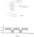
- Figure 1 schematically shows a spark ignition internal combustion engine E provided with supply means J, for example fuel injectors.
- the engine E is provided with an exhaust line, along which a three-way catalyst 3WC is housed. Upstream of the catalyst there is, along the exhaust line, a lambda sensor, preferably - though not necessarily - a binary lambda sensor B, which is designed to produce a feedback on the combustion of the internal combustion engine.
- a lambda sensor preferably - though not necessarily - a binary lambda sensor B, which is designed to produce a feedback on the combustion of the internal combustion engine.
- the sensor is a binary sensor, it switches between two logical conditions indicating a lean-burn condition and a rich-burn condition, respectively.
- a processing unit CPU monitors the control of the internal combustion engine E and, in particular, controls the injection of fuel into the cylinders of the engine by means of relative injectors J, which are supplied with fuel by a tank S.
- Said processing unit CPU implements a closed-loop control over said lambda sensor, thus causing the fuel supply of the internal combustion engine to continuously oscillate around the air/fuel stoichiometric ratio A/F so as to force the catalyst to alternately oscillate between an oxidizing phase and a reducing phase. This operation is carried out at least until a cut-off procedure takes place and, therefore, the storage of oxygen in the catalyst is assumed to be in ideal conditions.
- the processing unit upon detection of the cut-off, calculates the air flowing through the engine and estimates the consequent variation in the oxygen storage in the catalyst.
- the processing unit enriches the combustion so as to make up for said variation in the oxygen storage, thus taking it back to a condition prior to the cut-off.
- the enrichment is preferably carried out by polarizing the lean-burn/rich-burn alternations.
- the stay time of the rich-burn condition is greater than the stay time of the lean-burn condition.
- control plan is polarized, which means that it has a mean value which differs from the A/F stoichiometric ratio until the oxygen storage is restored to the aforesaid intermediate storage condition.
- the aforesaid intermediate condition preferably coincides with approximately 50% of the total O2 storage capacity.
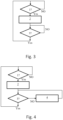
- FIG. 3 shows an example of a flowchart implementing the invention
- the catalyst can saturate, which means that it can reach the maximum oxygen storage possible.
- the method takes into account the maximum storage capacity of the catalyst in order to then carry out the aforesaid polarization within the limits of the excess oxygen actually stored in the catalyst.
- excess oxygen we mean the quantity, expressed in volume or moles, of oxygen exceeding the aforesaid intermediate storage condition.
- the method calculates the quantity of oxygen stored in the catalyst, through integration.
- the excess oxygen estimate is carried out in an integrative manner on consecutive cut-off conditions, taking into account enrichment operations that are alternated with the cut-off conditions.
- Figure 4 shows a variant of figure 3 , in which step 4 is added, during which a residual excess oxygen value is stored, as the excess oxygen is progressively eliminated. This evidently takes into account a new cut-off procedure which might prematurely interrupt step 3.
- the fuel supply managing method preferably comprises a proportional/integral closed-loop control over a signal for example a binary signal (ON/OFF), generated by the binary lambda sensor arranged upstream of the catalyst 3WC, the method comprising a procedure for continuously changing an air/fuel ratio between a lean-burn condition and a rich-burn condition and vice versa.
- the method comprises a procedure for detecting a cut-off condition, for calculating an excess oxygen stored in the cut-off condition relative to a predetermined optimum threshold and for controlling the supply of fuel to the internal combustion engine, after the end of the aforesaid cut-off condition, so as to neutralize said excess oxygen.
- Figure 2 shows a diagram of a supply signal of the internal combustion engine over time.
- ⁇ m indicates an A/F stoichiometric ratio condition with ends ⁇ 1 and ⁇ 2, between which the engine and, with it, also the relative catalyst are caused to oscillate.
- the A/F ratio is polarized towards a rich combustion by extending the stay time of the rich condition relative to the stay time of the lean condition. This all happens while the engine keeps oscillating between a lean combustion and a rich combustion.
- Figure 2 clearly shows that the hatched area above ⁇ m are significantly larger than the hatched areas under ⁇ m.
- the intensity of the enrichment can also be preferably controlled so as to be greater than the leaning; therefore, with reference to figure 2 , this means that the difference
- the fuel variation in a rich operating condition is greater than the fuel variation in a lean operating condition.
- the closed-loop control which is based on the binary signal generated by the binary lambda sensor, preferably determines oscillations around a reference value of the nominal stoichiometry, which was previously stored or calculated in the processing unit, until the correct oxygen storage is restored.
- the processing unit preferably implements a closed-loop control scheme with a proportional and integrative controller PI on the feedback branch, as suggested by the prior art documents concerning spark ignition Otto engines. This scheme, though, is changed as described above.
- the A/F ratio reference value is an ideal value, since it depends on an ideal fuel.
- the variation in the stored oxygen caused by the cut-off is preferably estimated by integrating the air flow flowing through the engine upon cut-off and by multiplying it by a conversion coefficient, which takes into account the capacity of the catalyst to hold back the oxygen contained in the air flow flowing through it.
- the internal combustion engine can be assumed to act like an ideal volumetric pump.
- This invention can be advantageously implemented by means of a computer program comprising encoding means for carrying out one or more steps of the method, when the program is run on a computer. Therefore, the scope of protection is extended to said computer program and, furthermore, to means that can be read by a computer and comprise a recorded message, said means that can be read by a computer comprising program encoding means for carrying out one or more steps of the method, when the program is run on a computer.
Landscapes
- Engineering & Computer Science (AREA)
- Chemical & Material Sciences (AREA)
- Combustion & Propulsion (AREA)
- Mechanical Engineering (AREA)
- General Engineering & Computer Science (AREA)
- Electrical Control Of Air Or Fuel Supplied To Internal-Combustion Engine (AREA)
- Exhaust Gas After Treatment (AREA)
- Ignition Installations For Internal Combustion Engines (AREA)
Description
- The invention relates to the field of methods and systems for managing a fuel supply of a spark ignition engine.
- In spark ignition engines, also known as Otto engines, the respect of the stoichiometric ratio is crucial in order to observe the limits set by laws on polluting emissions.
- In spark ignition stoichiometric engines, an exhaust gas after-treatment device (ATS) is used, which is based on a so-called "three-way catalyst" (3WC), which is capable of capturing and storing the oxygen present in the exhaust gases (O2) and, hence, has a so-called "Oxygen storage" capacity.
- By controlling the supply of fuel to the internal combustion engine between rich and lean mixture, the catalyst is forced to alternatively operate either in an oxidizing mode or in a reducing mode, thus burning unburned CO and HC or reducing NOx.
- In order for this alternation between oxidizing mode and reducing mode to be carried out, the oxygen storage of the three-way catalyst, hereinafter simply referred to as "catalyst", must be kept at an intermediate value of a relative maximum storage capacity, so that O2 can be stored in the presence of an oxygen-rich gas mixture and so that O2 can be released in the presence of an oxygen-poor gas mixture.
- The fuel supply of the internal combustion engine can be operated by means of a closed loop control, which uses a lambda sensor as a feedback signal in order to obtain a correct air/fuel ratio (A/F).
- Indeed, the efficiency with which the oxidation-reduction reactions take place in the catalyst depends on the stoichiometric ratio with which the mixture is burned in the engine and on the temperature of the catalyst itself. Linear lambda sensors can be used, which are precise and fast, allow the fuel supply of the internal combustion engine to be properly corrected and ensure the stoichiometry of the combustion.
- Binary lambda sensors can also be used, which are commonly known as "ON/OFF sensors". Unlike linear sensors, they do not need a dedicated hardware and their implementation is definitely cheaper.
- ON/OFF sensors are capable of producing, as feedback, a mere switching between a high level and a low level of the signal, exceeding a predetermined positive and negative threshold of the air/fuel ratio (A/F).
- Therefore, the control plan involves the implementation of an A/F forcing factor, which modulates the supply of fuel, increasing or decreasing the quantity of fuel injected into the cylinders, so as to alternatively cause the combustion taking place in the cylinder to lack oxygen or have excess oxygen.
- Therefore, the three-way catalyst is forced to work on a stoichiometric condition, in a bi-stable situation, namely continuously oscillating between an oxidizing operation and a reducing operation.
-
- When the accelerator is released, the engine is not supplied with fuel. This is commonly known as engine "cut-off", since the supply of fuel to the engine is "cut-off". In these conditions, the air pumped by the internal combustion engine flows through the ATS and, hence, the catalyst. Therefore, its oxygen storage capacity tends to saturate.
- When the fuel starts being injected again, the catalyst is forced to work in conditions that are not ideal and, therefore, the combustion must be temporarily altered, enriching it, in order to allow the catalyst to alternate between the reducing mode and the oxidizing mode.
- A known strategy involves continuously enriching the mixture for a predetermined amount of time with a duration that is fixed and previously calculated depending on the volume of the catalyst, i.e. On its geometry.
- This solution, though, is affected by some drawbacks because it suffers from some undesired effects, such as chugging and wear of the catalyst.
- The object of the invention is to provide a method for managing a fuel supply of a spark ignition engine, which is capable of better dealing with the consequences of a cut-off .
- The idea on which the invention is based is that of calculating an excess oxygen stored in the three-way catalyst relative to an optimum storage value, caused by a cut-off condition, and, at the end of the cut-off condition, determining and enrichment of the air/fuel ratio to neutralize said excess oxygen.
- Generally speaking, the fuel supply of the internal combustion engine is carried out oscillating between a lean-burn condition and a rich-burn condition, around the air/fuel stoichiometric ratio (A/F). Therefore, said adjustment can preferably be carried out by extending the rich-burn times relative to the lean-burn times.
- The intensity of the enrichment is also preferably controlled so as to always be greater than the leaning.
- In other words, relative to a stoichiometric ratio, the fuel variation in a rich operating condition is greater than the fuel variation in a lean operating condition.
- An "excess oxygen" evidently needs to be evaluated in relation to an ideal oxygen storage condition, which, as already mentioned above, is a mean storage condition between saturated and empty.
- According to the invention, the excess oxygen is all the oxygen stored during the cut-off.
- This oxygen is calculated based on the total volume of air taken in by the engine during the cut-off. To this aim, the total volume of air taken in can be measured by means of an air mass flow measuring device, which is arranged along the intake manifold, or can be estimated by assuming that the engine acts like a volumetric pump.
- Then, a coefficient is applied, which converts said total air volume flowing through the catalyst into oxygen actually held back in the catalyst. Said coefficient can take into account the efficiency of the catalyst and, therefore, can be a function of operating parameters, such as for example the temperature thereof.
- The corrective coefficient can also take into account the ageing of the catalysts.
- When dealing with a control carried out by means of a processing unit and of electric injectors, the quantity of fuel clearly corresponds to an electric control signal of the injectors.
- The (electric) control signal of the injectors injecting fuel into the cylinders depends on the air/fuel ratio value towards which the aforesaid forcing factor causes the controller to converge.
- If the alternating character of the control of the fuel supply of the internal combustion engine is not changed, the stay time of the rich phase can preferably be greater than the stay time of the lean phase, thus obtaining a polarization of the engine fuel supply control.
- The subject-matter of the invention comprises a method for managing a fuel supply of a spark ignition internal combustion engine and a fuel supply system implementing said method, besides a terrestrial vehicle or a fixed installation, for example for the generation of power, provided with a spark ignition internal combustion engine implementing the aforesaid method.
- Further objects and advantages of the invention will be best understood upon perusal of the following detailed description of an embodiment thereof (and of relative variants) with reference to the accompanying drawings merely showing non-limiting examples, wherein:
-
figure 1 schematically shows a spark ignition internal combustion engine provided with relative supply means and with an exhaust line, along which there are arranged a three-way catalyst and a binary lambda sensor according to the invention; -
figure 2 shows a time diagram of the switchings due to the implementation of a binary lambda sensor and of the method according to the invention; -
figures 3 and 4 show two flowcharts implementing as many preferred variants of the method according to the invention. - In the figures, the same numbers and the same reference letters indicate the same elements or components.
- The blocks of
figure 2 represented with a broken line are to be considered as optional. - The broken-line connections of
figure 1 represent analogue or digital electric lines. - For the purposes of the invention, the term "second" component does not imply the presence of a "first" component. As a matter of fact, these terms are only used for greater clarity and should not be interpreted in a limiting manner.
-
Figure 1 schematically shows a spark ignition internal combustion engine E provided with supply means J, for example fuel injectors. - The engine E is provided with an exhaust line, along which a three-way catalyst 3WC is housed. Upstream of the catalyst there is, along the exhaust line, a lambda sensor, preferably - though not necessarily - a binary lambda sensor B, which is designed to produce a feedback on the combustion of the internal combustion engine. When the sensor is a binary sensor, it switches between two logical conditions indicating a lean-burn condition and a rich-burn condition, respectively.
- A processing unit CPU monitors the control of the internal combustion engine E and, in particular, controls the injection of fuel into the cylinders of the engine by means of relative injectors J, which are supplied with fuel by a tank S.
- Said processing unit CPU implements a closed-loop control over said lambda sensor, thus causing the fuel supply of the internal combustion engine to continuously oscillate around the air/fuel stoichiometric ratio A/F so as to force the catalyst to alternately oscillate between an oxidizing phase and a reducing phase. This operation is carried out at least until a cut-off procedure takes place and, therefore, the storage of oxygen in the catalyst is assumed to be in ideal conditions.
- The processing unit, according to the invention, upon detection of the cut-off, calculates the air flowing through the engine and estimates the consequent variation in the oxygen storage in the catalyst.
- Consequently, the processing unit enriches the combustion so as to make up for said variation in the oxygen storage, thus taking it back to a condition prior to the cut-off.
- The enrichment is preferably carried out by polarizing the lean-burn/rich-burn alternations. In other words, the stay time of the rich-burn condition is greater than the stay time of the lean-burn condition.
- Owing to the above, the control plan is polarized, which means that it has a mean value which differs from the A/F stoichiometric ratio until the oxygen storage is restored to the aforesaid intermediate storage condition.
- The aforesaid intermediate condition preferably coincides with approximately 50% of the total O2 storage capacity.
-
Figure 3 shows an example of a flowchart implementing the invention: - In
step 1, the system continuously checks whether a cut-off condition occurs and, if so (yes), it carries out -
Step 2, during which the excess oxygen stored in the catalyst during the cut-off procedure is calculated and which is followed by -
Step 3, during which the air-fuel ratio is enriched until neutralization of the excess oxygen. - When the cut-off conditions lasts for a long time, for example due to a long downhill path, the catalyst can saturate, which means that it can reach the maximum oxygen storage possible.
- Therefore, the method takes into account the maximum storage capacity of the catalyst in order to then carry out the aforesaid polarization within the limits of the excess oxygen actually stored in the catalyst.
- This advantageously avoids overestimating the excess oxygen to be neutralized.
- By excess oxygen we mean the quantity, expressed in volume or moles, of oxygen exceeding the aforesaid intermediate storage condition.
- When the time needed to restore the oxygen storage is insufficient due to a new following cut-off, the method, according to a preferred variant of the invention, calculates the quantity of oxygen stored in the catalyst, through integration. In other words, the excess oxygen estimate is carried out in an integrative manner on consecutive cut-off conditions, taking into account enrichment operations that are alternated with the cut-off conditions.
-
Figure 4 shows a variant offigure 3 , in which step 4 is added, during which a residual excess oxygen value is stored, as the excess oxygen is progressively eliminated. This evidently takes into account a new cut-off procedure which might prematurely interruptstep 3. - This advantageously avoids underestimating the excess oxygen to be neutralized.
- If different consecutive cut-off procedures cause the catalyst to saturate, what described above evidently applies.
- The fuel supply managing method according to the invention preferably comprises a proportional/integral closed-loop control over a signal for example a binary signal (ON/OFF), generated by the binary lambda sensor arranged upstream of the catalyst 3WC, the method comprising a procedure for continuously changing an air/fuel ratio between a lean-burn condition and a rich-burn condition and vice versa. The method comprises a procedure for detecting a cut-off condition, for calculating an excess oxygen stored in the cut-off condition relative to a predetermined optimum threshold and for controlling the supply of fuel to the internal combustion engine, after the end of the aforesaid cut-off condition, so as to neutralize said excess oxygen.
Figure 2 shows a diagram of a supply signal of the internal combustion engine over time. - λm indicates an A/F stoichiometric ratio condition with ends λ1 and λ2, between which the engine and, with it, also the relative catalyst are caused to oscillate. According to the invention, the A/F ratio is polarized towards a rich combustion by extending the stay time of the rich condition relative to the stay time of the lean condition. This all happens while the engine keeps oscillating between a lean combustion and a rich combustion.
-
Figure 2 clearly shows that the hatched area above λm are significantly larger than the hatched areas under λm. - The intensity of the enrichment can also be preferably controlled so as to be greater than the leaning; therefore, with reference to
figure 2 , this means that the difference | λ1 - λm | is greater than | λm - λ2 | , unlike what is shown infigure 2 . - In other words, relative to a stoichiometric ratio, the fuel variation in a rich operating condition is greater than the fuel variation in a lean operating condition.
- This all happens while the engine keeps oscillating between a lean combustion and a rich combustion.
- The closed-loop control, which is based on the binary signal generated by the binary lambda sensor, preferably determines oscillations around a reference value of the nominal stoichiometry, which was previously stored or calculated in the processing unit, until the correct oxygen storage is restored.
- The processing unit preferably implements a closed-loop control scheme with a proportional and integrative controller PI on the feedback branch, as suggested by the prior art documents concerning spark ignition Otto engines. This scheme, though, is changed as described above.
- The A/F ratio reference value is an ideal value, since it depends on an ideal fuel.
- The variation in the stored oxygen caused by the cut-off is preferably estimated by integrating the air flow flowing through the engine upon cut-off and by multiplying it by a conversion coefficient, which takes into account the capacity of the catalyst to hold back the oxygen contained in the air flow flowing through it.
- In the absence of an air mass flow measuring device arranged along the intake manifold of the engine, the internal combustion engine can be assumed to act like an ideal volumetric pump.
- This invention can be advantageously implemented by means of a computer program comprising encoding means for carrying out one or more steps of the method, when the program is run on a computer. Therefore, the scope of protection is extended to said computer program and, furthermore, to means that can be read by a computer and comprise a recorded message, said means that can be read by a computer comprising program encoding means for carrying out one or more steps of the method, when the program is run on a computer.
- The non-limiting example described above can be subjected to variations, without for this reason going beyond the scope of protection of the invention, comprising all equivalent embodiments for a person skilled in the art. When reading the description above, a skilled person can carry out the subject-matter of the invention without introducing further manufacturing details. The elements and features contained in the different preferred embodiments, drawings included, can be combined with one another, without for this reason going beyond the scope of protection of this patent application. The information contained in the part concerning the state of art only serves the purpose of better understanding the invention and does not represent a declaration of existence of the items described. Furthermore, if not specifically excluded by the detailed description, the information contained in the part concerning the state of art should be considered as an integral part of the invention.
Claims (10)
- A method for managing a fuel supply of a spark ignition internal combustion engine (E), the engine (E) being provided with+ a fuel supply system (J) suitable for dosing fuel in response to a supply signal,+ a three-way catalyst (3WC) connected to an exhaust manifold of the internal combustion engine having a predetermined oxygen storage capacity,the method comprising a procedure for controlling said combustion so as to alternately oscillate between a lean-burn condition and a rich-burn condition, at least when the catalyst is in a condition of optimal oxygen storage,the method comprising the following steps:- a first step (1) for detecting a cut-off condition, wherein a fuel injection is inhibited,- a second step (2), upon detection of the cut-off condition, for calculating an excess oxygen stored in said catalyst during the cut-off condition with respect to said optimal oxygen storage, on the basis of a calculation of air ingested by said internal combustion engine (E) during said cut-off condition;- a third step (3) for controlling said fuel supply of the internal combustion engine, at the end of said cut-off condition, so as to neutralize exclusively said excess oxygen with respect to said optimum storage value,wherein said neutralization of said excess oxygen is achieved by increasing the rich-burn time with respect to the lean-burn time during said alternate oscillation between said lean-burn condition and said rich-burn condition or by enriching, during said rich-burn condition, more than leaning during said lean-burn condition.
- The method according to claim 1, wherein said optimum storage value is between 40 - 60% of a catalyst maximum storage capacity, preferably greater than 50%.
- The method according to any of the preceding claims, wherein said control of the engine fuel supply is achieved in closed loop on the basis of a signal generated by a lambda probe (L), arranged immediately upstream of said catalyst (3WC), for returning a measurement of an air/fuel ratio (A/F).
- The method according to claim 3, wherein said lambda probe is of the binary type and is adapted to switch between two logic conditions indicating lean and rich burn, respectively.
- The method according to any of the preceding claims, wherein said calculation of air ingested by said internal combustion engine is based on a model of the internal combustion engine functioning as an ideal volumetric pump.
- The method according to any one of the preceding claims, wherein said excess oxygen estimate is carried out in an integrative manner on consecutive cut-off conditions, taking into account enrichment operations that alternate the cut-off conditions.
- A system for managing a fuel supply of an internal combustion engine provided with a+ a fuel supply system (J) suitable for dosing fuel in response to a supply signal,+ a three-way catalyst (3WC) connected to an exhaust manifold of the internal combustion engine,characterized in that said managing system comprises a processing unit (CPU), configured for performing all the steps of any one of the claims 1 - 2 and 5 - 6.
- The system according to claim 7, further comprising a lambda probe (L), arranged immediately upstream of said catalyst (3WC), for returning a measurement of an air/fuel ratio (A/F) and wherein said processing unit is further configured for performing said control of the internal combustion engine in closed loop on the basis of said measurement of said air/fuel ratio (A/F).
- The system according to claim 8, wherein said lambda probe is of the binary type and is adapted to switch between two logic conditions indicating lean and rich burn, respectively.
- vehicle or a fixed installation provided with+ an internal combustion engine (E) having a fuel supply system (J) suitable for dosing fuel in response to a supply signal,+ a three-way catalyst (3WC) connected to an exhaust manifold of the internal combustion engine,+ a system for managing a fue1 supply of said internal combustion engine according to any of the claims 7-9.
Applications Claiming Priority (2)
| Application Number | Priority Date | Filing Date | Title |
|---|---|---|---|
| IT102018000003891A IT201800003891A1 (en) | 2018-03-22 | 2018-03-22 | METHOD OF MANAGING A POWER SUPPLY OF AN INTERNAL COMBUSTION ENGINE WITH COMMANDED IGNITION AND IMPLEMENTING POWER SUPPLY SYSTEM SAID METHOD |
| PCT/IB2019/052350 WO2019180678A1 (en) | 2018-03-22 | 2019-03-22 | Method for managing a fuel supply of a spark ignition internal combustion engine and a supply system implementing said method |
Publications (2)
| Publication Number | Publication Date |
|---|---|
| EP3768959A1 EP3768959A1 (en) | 2021-01-27 |
| EP3768959B1 true EP3768959B1 (en) | 2025-01-08 |
Family
ID=62751267
Family Applications (1)
| Application Number | Title | Priority Date | Filing Date |
|---|---|---|---|
| EP19721065.1A Active EP3768959B1 (en) | 2018-03-22 | 2019-03-22 | Method for managing a fuel supply of a spark ignition internal combustion engine and a supply system implementing said method |
Country Status (4)
| Country | Link |
|---|---|
| EP (1) | EP3768959B1 (en) |
| CN (1) | CN112074659B (en) |
| IT (1) | IT201800003891A1 (en) |
| WO (1) | WO2019180678A1 (en) |
Citations (1)
| Publication number | Priority date | Publication date | Assignee | Title |
|---|---|---|---|---|
| JP2005076496A (en) * | 2003-08-29 | 2005-03-24 | Toyota Motor Corp | Fuel injection control device for internal combustion engine |
Family Cites Families (9)
| Publication number | Priority date | Publication date | Assignee | Title |
|---|---|---|---|---|
| JP3528739B2 (en) * | 2000-02-16 | 2004-05-24 | 日産自動車株式会社 | Engine exhaust purification device |
| US6363316B1 (en) * | 2000-05-13 | 2002-03-26 | Ford Global Technologies, Inc. | Cylinder air charge estimation using observer-based adaptive control |
| JP4289185B2 (en) * | 2004-03-16 | 2009-07-01 | トヨタ自動車株式会社 | Air-fuel ratio control device for internal combustion engine |
| DE102009010887B3 (en) * | 2009-02-27 | 2010-04-29 | Continental Automotive Gmbh | Method and device for operating an internal combustion engine |
| EP2253821B1 (en) * | 2009-05-22 | 2011-07-20 | Umicore AG & Co. KG | Method for cleaning exhaust gases of a combustion motor with a catalytic convertor |
| WO2011128967A1 (en) * | 2010-04-12 | 2011-10-20 | トヨタ自動車株式会社 | Controller for internal combustion engine |
| US9932877B2 (en) * | 2013-05-10 | 2018-04-03 | Ford Global Technologies, Llc | Integrated fuel catalyst monitor |
| JP6252357B2 (en) * | 2014-05-26 | 2017-12-27 | トヨタ自動車株式会社 | Control device for internal combustion engine |
| JP6269427B2 (en) * | 2014-10-03 | 2018-01-31 | トヨタ自動車株式会社 | Control device for internal combustion engine |
-
2018
- 2018-03-22 IT IT102018000003891A patent/IT201800003891A1/en unknown
-
2019
- 2019-03-22 WO PCT/IB2019/052350 patent/WO2019180678A1/en not_active Ceased
- 2019-03-22 EP EP19721065.1A patent/EP3768959B1/en active Active
- 2019-03-22 CN CN201980020911.1A patent/CN112074659B/en active Active
Patent Citations (1)
| Publication number | Priority date | Publication date | Assignee | Title |
|---|---|---|---|---|
| JP2005076496A (en) * | 2003-08-29 | 2005-03-24 | Toyota Motor Corp | Fuel injection control device for internal combustion engine |
Also Published As
| Publication number | Publication date |
|---|---|
| IT201800003891A1 (en) | 2019-09-22 |
| EP3768959A1 (en) | 2021-01-27 |
| BR112020019070A2 (en) | 2020-12-29 |
| CN112074659B (en) | 2023-09-05 |
| WO2019180678A1 (en) | 2019-09-26 |
| CN112074659A (en) | 2020-12-11 |
Similar Documents
| Publication | Publication Date | Title |
|---|---|---|
| JP6256240B2 (en) | Control device for internal combustion engine | |
| RU2609601C1 (en) | Control system for internal combustion engine | |
| AU2014330332B2 (en) | Control device of internal combustion engine | |
| JP6098735B2 (en) | Control device for internal combustion engine | |
| JP2582586B2 (en) | Air-fuel ratio control device for internal combustion engine | |
| CN105971700A (en) | Exhaust purification system of internal combustion engine | |
| JP6252357B2 (en) | Control device for internal combustion engine | |
| JP6834917B2 (en) | Exhaust purification device for internal combustion engine | |
| JP6361699B2 (en) | Control device for internal combustion engine | |
| JP2014066154A (en) | Control device of internal combustion engine | |
| JP5326969B2 (en) | Fuel supply control device for internal combustion engine | |
| WO1998012423A1 (en) | Engine control device | |
| JP3687495B2 (en) | Exhaust gas purification device for internal combustion engine | |
| JP2008261820A (en) | The present invention relates to an exhaust particulate measurement device for an internal combustion engine. | |
| JP6269371B2 (en) | Internal combustion engine | |
| EP3768959B1 (en) | Method for managing a fuel supply of a spark ignition internal combustion engine and a supply system implementing said method | |
| JP2018003777A (en) | Control device of internal combustion engine | |
| JP6350414B2 (en) | Control device for internal combustion engine | |
| JP3608443B2 (en) | Air-fuel ratio control device for internal combustion engine | |
| JP2015172356A (en) | Control device for internal combustion engine | |
| BR112020019070B1 (en) | METHOD FOR MANAGING THE POWER SUPPLY OF AN INTERNAL COMBUSTION ENGINE WITH SPARK IGNITION, SYSTEM FOR MANAGING THE POWER SUPPLY OF AN INTERNAL COMBUSTION ENGINE AND VEHICLE OR FIXED INSTALLATION | |
| JP6156278B2 (en) | Control device for internal combustion engine | |
| JP4064092B2 (en) | Engine air-fuel ratio control device | |
| JP2004076591A (en) | Secondary air supply control device for internal combustion engine | |
| JP2008261254A (en) | Control device for internal combustion engine |
Legal Events
| Date | Code | Title | Description |
|---|---|---|---|
| STAA | Information on the status of an ep patent application or granted ep patent |
Free format text: STATUS: UNKNOWN |
|
| STAA | Information on the status of an ep patent application or granted ep patent |
Free format text: STATUS: THE INTERNATIONAL PUBLICATION HAS BEEN MADE |
|
| PUAI | Public reference made under article 153(3) epc to a published international application that has entered the european phase |
Free format text: ORIGINAL CODE: 0009012 |
|
| STAA | Information on the status of an ep patent application or granted ep patent |
Free format text: STATUS: REQUEST FOR EXAMINATION WAS MADE |
|
| 17P | Request for examination filed |
Effective date: 20200916 |
|
| AK | Designated contracting states |
Kind code of ref document: A1 Designated state(s): AL AT BE BG CH CY CZ DE DK EE ES FI FR GB GR HR HU IE IS IT LI LT LU LV MC MK MT NL NO PL PT RO RS SE SI SK SM TR |
|
| AX | Request for extension of the european patent |
Extension state: BA ME |
|
| RIN1 | Information on inventor provided before grant (corrected) |
Inventor name: CARO, MARCELLO Inventor name: AIMAR, BRUNO Inventor name: BRUCATO, ALDO |
|
| DAV | Request for validation of the european patent (deleted) | ||
| DAX | Request for extension of the european patent (deleted) | ||
| STAA | Information on the status of an ep patent application or granted ep patent |
Free format text: STATUS: EXAMINATION IS IN PROGRESS |
|
| 17Q | First examination report despatched |
Effective date: 20221116 |
|
| GRAP | Despatch of communication of intention to grant a patent |
Free format text: ORIGINAL CODE: EPIDOSNIGR1 |
|
| STAA | Information on the status of an ep patent application or granted ep patent |
Free format text: STATUS: GRANT OF PATENT IS INTENDED |
|
| INTG | Intention to grant announced |
Effective date: 20240924 |
|
| GRAS | Grant fee paid |
Free format text: ORIGINAL CODE: EPIDOSNIGR3 |
|
| GRAA | (expected) grant |
Free format text: ORIGINAL CODE: 0009210 |
|
| STAA | Information on the status of an ep patent application or granted ep patent |
Free format text: STATUS: THE PATENT HAS BEEN GRANTED |
|
| AK | Designated contracting states |
Kind code of ref document: B1 Designated state(s): AL AT BE BG CH CY CZ DE DK EE ES FI FR GB GR HR HU IE IS IT LI LT LU LV MC MK MT NL NO PL PT RO RS SE SI SK SM TR |
|
| REG | Reference to a national code |
Ref country code: GB Ref legal event code: FG4D |
|
| REG | Reference to a national code |
Ref country code: CH Ref legal event code: EP |
|
| REG | Reference to a national code |
Ref country code: DE Ref legal event code: R096 Ref document number: 602019064580 Country of ref document: DE |
|
| REG | Reference to a national code |
Ref country code: IE Ref legal event code: FG4D |
|
| REG | Reference to a national code |
Ref country code: LT Ref legal event code: MG9D |
|
| REG | Reference to a national code |
Ref country code: NL Ref legal event code: MP Effective date: 20250108 |
|
| REG | Reference to a national code |
Ref country code: AT Ref legal event code: MK05 Ref document number: 1758465 Country of ref document: AT Kind code of ref document: T Effective date: 20250108 |
|
| PG25 | Lapsed in a contracting state [announced via postgrant information from national office to epo] |
Ref country code: NL Free format text: LAPSE BECAUSE OF FAILURE TO SUBMIT A TRANSLATION OF THE DESCRIPTION OR TO PAY THE FEE WITHIN THE PRESCRIBED TIME-LIMIT Effective date: 20250108 |
|
| PG25 | Lapsed in a contracting state [announced via postgrant information from national office to epo] |
Ref country code: RS Free format text: LAPSE BECAUSE OF FAILURE TO SUBMIT A TRANSLATION OF THE DESCRIPTION OR TO PAY THE FEE WITHIN THE PRESCRIBED TIME-LIMIT Effective date: 20250408 |
|
| PG25 | Lapsed in a contracting state [announced via postgrant information from national office to epo] |
Ref country code: FI Free format text: LAPSE BECAUSE OF FAILURE TO SUBMIT A TRANSLATION OF THE DESCRIPTION OR TO PAY THE FEE WITHIN THE PRESCRIBED TIME-LIMIT Effective date: 20250108 |
|
| PG25 | Lapsed in a contracting state [announced via postgrant information from national office to epo] |
Ref country code: PL Free format text: LAPSE BECAUSE OF FAILURE TO SUBMIT A TRANSLATION OF THE DESCRIPTION OR TO PAY THE FEE WITHIN THE PRESCRIBED TIME-LIMIT Effective date: 20250108 |
|
| PG25 | Lapsed in a contracting state [announced via postgrant information from national office to epo] |
Ref country code: ES Free format text: LAPSE BECAUSE OF FAILURE TO SUBMIT A TRANSLATION OF THE DESCRIPTION OR TO PAY THE FEE WITHIN THE PRESCRIBED TIME-LIMIT Effective date: 20250108 |
|
| PG25 | Lapsed in a contracting state [announced via postgrant information from national office to epo] |
Ref country code: NO Free format text: LAPSE BECAUSE OF FAILURE TO SUBMIT A TRANSLATION OF THE DESCRIPTION OR TO PAY THE FEE WITHIN THE PRESCRIBED TIME-LIMIT Effective date: 20250408 Ref country code: IS Free format text: LAPSE BECAUSE OF FAILURE TO SUBMIT A TRANSLATION OF THE DESCRIPTION OR TO PAY THE FEE WITHIN THE PRESCRIBED TIME-LIMIT Effective date: 20250508 |
|
| PG25 | Lapsed in a contracting state [announced via postgrant information from national office to epo] |
Ref country code: HR Free format text: LAPSE BECAUSE OF FAILURE TO SUBMIT A TRANSLATION OF THE DESCRIPTION OR TO PAY THE FEE WITHIN THE PRESCRIBED TIME-LIMIT Effective date: 20250108 |
|
| PG25 | Lapsed in a contracting state [announced via postgrant information from national office to epo] |
Ref country code: LV Free format text: LAPSE BECAUSE OF FAILURE TO SUBMIT A TRANSLATION OF THE DESCRIPTION OR TO PAY THE FEE WITHIN THE PRESCRIBED TIME-LIMIT Effective date: 20250108 Ref country code: PT Free format text: LAPSE BECAUSE OF FAILURE TO SUBMIT A TRANSLATION OF THE DESCRIPTION OR TO PAY THE FEE WITHIN THE PRESCRIBED TIME-LIMIT Effective date: 20250508 |
|
| PG25 | Lapsed in a contracting state [announced via postgrant information from national office to epo] |
Ref country code: GR Free format text: LAPSE BECAUSE OF FAILURE TO SUBMIT A TRANSLATION OF THE DESCRIPTION OR TO PAY THE FEE WITHIN THE PRESCRIBED TIME-LIMIT Effective date: 20250409 Ref country code: BG Free format text: LAPSE BECAUSE OF FAILURE TO SUBMIT A TRANSLATION OF THE DESCRIPTION OR TO PAY THE FEE WITHIN THE PRESCRIBED TIME-LIMIT Effective date: 20250108 |
|
| PG25 | Lapsed in a contracting state [announced via postgrant information from national office to epo] |
Ref country code: AT Free format text: LAPSE BECAUSE OF FAILURE TO SUBMIT A TRANSLATION OF THE DESCRIPTION OR TO PAY THE FEE WITHIN THE PRESCRIBED TIME-LIMIT Effective date: 20250108 |
|
| PG25 | Lapsed in a contracting state [announced via postgrant information from national office to epo] |
Ref country code: SE Free format text: LAPSE BECAUSE OF FAILURE TO SUBMIT A TRANSLATION OF THE DESCRIPTION OR TO PAY THE FEE WITHIN THE PRESCRIBED TIME-LIMIT Effective date: 20250108 |
|
| PG25 | Lapsed in a contracting state [announced via postgrant information from national office to epo] |
Ref country code: SM Free format text: LAPSE BECAUSE OF FAILURE TO SUBMIT A TRANSLATION OF THE DESCRIPTION OR TO PAY THE FEE WITHIN THE PRESCRIBED TIME-LIMIT Effective date: 20250108 |
|
| REG | Reference to a national code |
Ref country code: DE Ref legal event code: R097 Ref document number: 602019064580 Country of ref document: DE |
|
| PG25 | Lapsed in a contracting state [announced via postgrant information from national office to epo] |
Ref country code: DK Free format text: LAPSE BECAUSE OF FAILURE TO SUBMIT A TRANSLATION OF THE DESCRIPTION OR TO PAY THE FEE WITHIN THE PRESCRIBED TIME-LIMIT Effective date: 20250108 |
|
| PG25 | Lapsed in a contracting state [announced via postgrant information from national office to epo] |
Ref country code: MC Free format text: LAPSE BECAUSE OF FAILURE TO SUBMIT A TRANSLATION OF THE DESCRIPTION OR TO PAY THE FEE WITHIN THE PRESCRIBED TIME-LIMIT Effective date: 20250108 |
|
| PG25 | Lapsed in a contracting state [announced via postgrant information from national office to epo] |
Ref country code: EE Free format text: LAPSE BECAUSE OF FAILURE TO SUBMIT A TRANSLATION OF THE DESCRIPTION OR TO PAY THE FEE WITHIN THE PRESCRIBED TIME-LIMIT Effective date: 20250108 Ref country code: CZ Free format text: LAPSE BECAUSE OF FAILURE TO SUBMIT A TRANSLATION OF THE DESCRIPTION OR TO PAY THE FEE WITHIN THE PRESCRIBED TIME-LIMIT Effective date: 20250108 |
|
| REG | Reference to a national code |
Ref country code: CH Ref legal event code: H13 Free format text: ST27 STATUS EVENT CODE: U-0-0-H10-H13 (AS PROVIDED BY THE NATIONAL OFFICE) Effective date: 20251023 |
|
| PG25 | Lapsed in a contracting state [announced via postgrant information from national office to epo] |
Ref country code: RO Free format text: LAPSE BECAUSE OF FAILURE TO SUBMIT A TRANSLATION OF THE DESCRIPTION OR TO PAY THE FEE WITHIN THE PRESCRIBED TIME-LIMIT Effective date: 20250108 |
|
| PG25 | Lapsed in a contracting state [announced via postgrant information from national office to epo] |
Ref country code: SK Free format text: LAPSE BECAUSE OF FAILURE TO SUBMIT A TRANSLATION OF THE DESCRIPTION OR TO PAY THE FEE WITHIN THE PRESCRIBED TIME-LIMIT Effective date: 20250108 |
|
| PLBE | No opposition filed within time limit |
Free format text: ORIGINAL CODE: 0009261 |
|
| STAA | Information on the status of an ep patent application or granted ep patent |
Free format text: STATUS: NO OPPOSITION FILED WITHIN TIME LIMIT |
|
| PG25 | Lapsed in a contracting state [announced via postgrant information from national office to epo] |
Ref country code: LU Free format text: LAPSE BECAUSE OF NON-PAYMENT OF DUE FEES Effective date: 20250322 |
|
| REG | Reference to a national code |
Ref country code: BE Ref legal event code: MM Effective date: 20250331 |
|
| 26N | No opposition filed |
Effective date: 20251009 |
|
| GBPC | Gb: european patent ceased through non-payment of renewal fee |
Effective date: 20250408 |
|
| PG25 | Lapsed in a contracting state [announced via postgrant information from national office to epo] |
Ref country code: GB Free format text: LAPSE BECAUSE OF NON-PAYMENT OF DUE FEES Effective date: 20250408 |
|
| PG25 | Lapsed in a contracting state [announced via postgrant information from national office to epo] |
Ref country code: IT Free format text: LAPSE BECAUSE OF NON-PAYMENT OF DUE FEES Effective date: 20250322 |
|
| PG25 | Lapsed in a contracting state [announced via postgrant information from national office to epo] |
Ref country code: BE Free format text: LAPSE BECAUSE OF NON-PAYMENT OF DUE FEES Effective date: 20250331 |
|
| PG25 | Lapsed in a contracting state [announced via postgrant information from national office to epo] |
Ref country code: CH Free format text: LAPSE BECAUSE OF NON-PAYMENT OF DUE FEES Effective date: 20250331 |
|
| PG25 | Lapsed in a contracting state [announced via postgrant information from national office to epo] |
Ref country code: IE Free format text: LAPSE BECAUSE OF NON-PAYMENT OF DUE FEES Effective date: 20250322 |
|
| PGFP | Annual fee paid to national office [announced via postgrant information from national office to epo] |
Ref country code: DE Payment date: 20260320 Year of fee payment: 8 |
|
| PGFP | Annual fee paid to national office [announced via postgrant information from national office to epo] |
Ref country code: FR Payment date: 20260323 Year of fee payment: 8 |