EP3768627B1 - Reconstitution of independent beverage flows - Google Patents
Reconstitution of independent beverage flows Download PDFInfo
- Publication number
- EP3768627B1 EP3768627B1 EP19770724.3A EP19770724A EP3768627B1 EP 3768627 B1 EP3768627 B1 EP 3768627B1 EP 19770724 A EP19770724 A EP 19770724A EP 3768627 B1 EP3768627 B1 EP 3768627B1
- Authority
- EP
- European Patent Office
- Prior art keywords
- liquid
- outlet
- dispensing
- fluid
- dispensing assembly
- Prior art date
- Legal status (The legal status is an assumption and is not a legal conclusion. Google has not performed a legal analysis and makes no representation as to the accuracy of the status listed.)
- Active
Links
Images




Classifications
-
- B—PERFORMING OPERATIONS; TRANSPORTING
- B67—OPENING, CLOSING OR CLEANING BOTTLES, JARS OR SIMILAR CONTAINERS; LIQUID HANDLING
- B67D—DISPENSING, DELIVERING OR TRANSFERRING LIQUIDS, NOT OTHERWISE PROVIDED FOR
- B67D1/00—Apparatus or devices for dispensing beverages on draught
- B67D1/0042—Details of specific parts of the dispensers
- B67D1/0043—Mixing devices for liquids
- B67D1/0051—Mixing devices for liquids for mixing outside the nozzle
- B67D1/0052—Mixing devices for liquids for mixing outside the nozzle by means for directing respective streams together
-
- B—PERFORMING OPERATIONS; TRANSPORTING
- B67—OPENING, CLOSING OR CLEANING BOTTLES, JARS OR SIMILAR CONTAINERS; LIQUID HANDLING
- B67D—DISPENSING, DELIVERING OR TRANSFERRING LIQUIDS, NOT OTHERWISE PROVIDED FOR
- B67D1/00—Apparatus or devices for dispensing beverages on draught
- B67D1/0015—Apparatus or devices for dispensing beverages on draught the beverage being prepared by mixing at least two liquid components
- B67D1/0021—Apparatus or devices for dispensing beverages on draught the beverage being prepared by mixing at least two liquid components the components being mixed at the time of dispensing, i.e. post-mix dispensers
-
- B—PERFORMING OPERATIONS; TRANSPORTING
- B67—OPENING, CLOSING OR CLEANING BOTTLES, JARS OR SIMILAR CONTAINERS; LIQUID HANDLING
- B67D—DISPENSING, DELIVERING OR TRANSFERRING LIQUIDS, NOT OTHERWISE PROVIDED FOR
- B67D2210/00—Indexing scheme relating to aspects and details of apparatus or devices for dispensing beverages on draught or for controlling flow of liquids under gravity from storage containers for dispensing purposes
- B67D2210/00028—Constructional details
- B67D2210/00031—Housing
-
- B—PERFORMING OPERATIONS; TRANSPORTING
- B67—OPENING, CLOSING OR CLEANING BOTTLES, JARS OR SIMILAR CONTAINERS; LIQUID HANDLING
- B67D—DISPENSING, DELIVERING OR TRANSFERRING LIQUIDS, NOT OTHERWISE PROVIDED FOR
- B67D2210/00—Indexing scheme relating to aspects and details of apparatus or devices for dispensing beverages on draught or for controlling flow of liquids under gravity from storage containers for dispensing purposes
- B67D2210/00028—Constructional details
- B67D2210/00047—Piping
- B67D2210/00049—Pipes
Definitions
- the technology disclosed herein relates generally to beverage dispensers, and more particularly to structures and techniques for combining independent beverage flows.
- Liquid dispensers are appliances that prepare drinks for users. Often, a dispenser will include a connection to a water source, such as the plumbing of a building or an independent water reservoir, and a receiver that receives a package containing a flavoring agent. The water and the flavoring agent are mixed in the appliance before being dispensed from the appliance into the user's cup.
- a water source such as the plumbing of a building or an independent water reservoir
- a receiver that receives a package containing a flavoring agent.
- the water and the flavoring agent are mixed in the appliance before being dispensed from the appliance into the user's cup.
- Postmix processes have historically combined the flavoring agent and water immediately before delivery into a cup, or concurrently as independent streams of water and flavoring agent into the cup, allowing mixing to occur in the cup.
- the latter option providing independent streams of water and flavoring agent to be mixed in a cup, suffers from a number of issues including possible incomplete mixing due to insufficient pressures, turbulence, or material properties that resist easy mixing. Additionally, the sequential dispensing of independent streams is also more time consuming, noisy, and can offer a less satisfactory user experience.
- combining the flavoring agent and water immediately before delivery into a cup presents additional challenges. This in-air mixing relies on precise timing and accurate flow paths to ensure consistent mixing and to ensure accurate dispensing into the desired cup and avoiding an undesirable spill.
- a dispenser including a plurality of beverage supply sources adapted to supply a plurality of beverage constituents.
- the beverage mixing apparatus includes a first aperture adapted to receive the plurality of beverage constituents, a second aperture adapted to dispense a mixture of the beverage constituents, and a conduit interposed between the first and second apertures and adapted to mix the plurality of beverage constituents.
- a dispensing nozzle is engaged with the second aperture, and a sensor device is disposed along the conduit, proximal to the second aperture, which is adapted to adjust the supply of a beverage constituent.
- JP 2013 014338 A discloses a dispensing and mixing assembly comprising coaxial cylindrical tubes. Said assembly differs from the invention as in claim 1 in that it lacks apertures in the cylindrical wall of the inner tube.
- the invention relates to a dispensing assembly according to claim 1 and a method for dispensing a beverage according to claim 6.
- One or more apertures can be defined through the cylindrical wall of the first element.
- the cylindrical wall can separate the first and second liquids.
- the one or more apertures are arranged to limit passage of the second fluid toward the first outlet when the second fluid exhibits a dispensing pressure.
- the one or more apertures can be further arranged to allow passage of the second fluid toward the second outlet when the second fluid exhibits a cleaning pressure that is greater than the dispensing pressure.
- the wall extends beyond a lowermost bottom surface of the annular wall.
- the internal wall can taper toward the first outlet.
- the dispensing assembly can further include one or more apertures defined through the internal wall to selectively connect the first and second liquid chambers.
- the one or more apertures can be arranged for, at a first cleaning pressure, flow of the second liquid toward the first outlet. Further, the one or more apertures can be arranged for, at a second dispensing pressure that is less than the first cleaning pressure, restriction of the second liquid toward the first outlet.
- the internal liquid stream and the annular liquid column converge at a location downstream of both the first outlet and the second outlet.
- the location can be spaced at a first distance from the first outlet, and the location is spaced at a second distance from the second outlet. As such, the second distance can be greater than the first distance.
- the The first liquid can include a flavoring medium.
- the second liquid can include a carbonated liquid.
- the method can further include applying a flow rate that causes the internal fluid stream and the annular liquid column to converge at a distance away from the first outlet and the second outlet.
- cross-hatching or shading in the accompanying figures is generally provided to clarify the boundaries between adjacent elements and also to facilitate legibility of the figures. Accordingly, neither the presence nor the absence of cross-hatching or shading conveys or indicates any preference or requirement for particular materials, material properties, element proportions, element dimensions, commonalities of similarly illustrated elements, or any other characteristic, attribute, or property for any element illustrated in the accompanying figures.
- An appliance can be used to prepare beverages.
- the appliance is a brewing machine that prepares beverages like coffee, tea, hot chocolate, cider, and the like.
- the appliance is a machine used to mix the ingredients for carbonated drinks, fruit drinks, milk products, alcoholic drinks, other types of drinks, or combinations thereof.
- the appliance can include a dispenser that is in communication with a first liquid chamber and a second liquid chamber.
- the first liquid chamber and the second liquid chamber can include different types of liquids, or constituents of the desired final beverage.
- one of the liquid chambers can contain water, carbonated water, milk, or another type of base liquid, while the other chamber includes a flavoring agent.
- the flavoring agent can include a concentrate, a syrup, a supplement, a dye, another type of flavoring agent, or combinations thereof.
- liquid from each of the first liquid chamber and the second liquid chamber is dispensed out of the appliance simultaneously.
- the first liquid is dispensed out of a first outlet
- the second liquid is dispensed out of a second outlet.
- the first outlet is incorporated into a tube that is in fluid communication with a first liquid chamber.
- the tube includes a chamber end that receives the first liquid.
- a dispensing end of the tube is opposite of the chamber end, and the first outlet is defined in the dispensing end.
- the first liquid forms a liquid stream that is directed to a container, such as a cup.
- the second outlet can be formed by a wall that directs the second liquid towards the outside exterior of the tube.
- An opening in the wall can collectively form a second outlet with the exterior side of the tube.
- the dispensing end of the tube can protrude beyond the second outlet.
- the second outlet forms a ring-like shape through which the second liquid is dispensed.
- the second liquid forms an annular liquid column that surrounds the internal liquid stream of the first liquid.
- the internal fluid stream With the internal fluid stream surrounded by the annular fluid column, the internal fluid stream can not be visible to an observer looking in from the outside because the internal liquid stream is obscured by the annular liquid column.
- a gap can exist between them.
- the annular liquid column can converge on itself.
- the annular liquid column can converge towards a central region as the liquids progressively move away from the dispenser until the annular liquid column intersects the internal liquid stream.
- the interaction between the internal liquid stream and the annular liquid column causes the two liquids to mix in the air within the ambient environment outside of the appliance.
- the appliance By mixing the first liquid and the second liquid outside the appliance, the appliance can be simplified without needing a mixing chamber. This simplifies the construction and lowers the cost of the appliance.
- Another advantage of mixing the first liquid and the second liquid outside of the appliance is an ability to control the amount of turbulence between the two liquids as they mix.
- the second liquid includes carbonation
- mixing the two liquids together can result in the carbonation forming bubbles during mixing that causes the carbonation to exit the liquids before the liquids enter into a user's cup.
- the amount of turbulence can be controlled by varying the flow rate of the first and second liquids. By controlling the flow rates, and therefore the degree of turbulence during mixing, the carbonation can be preserved within the liquids.
- FIG. 1 depicts an example of an appliance 100 that is used to make beverages, such as the appliances discussed above and described in greater detail below.
- the appliance 100 can include a dispensing assembly 102 operable to dispense a beverage.
- the dispensing assembly 102 can dispense a beverage into a container 104, such as a cup, a mug, a bottle, or the like.
- the appliance 100 can include a dispensing area 106, such as a cavity or recess defined within the appliance 100 adjacent to the dispensing assembly 102.
- the container 104 can be positioned within the dispensing area 106 to dispense the beverage into the container 104.
- the container 104 can be positioned on a shelf 108 defined below the dispensing assembly 102.
- the dispensing assembly 102 can be movable relative to the appliance 100.
- the dispensing assembly 102 can be extendable from the appliance 100 to facilitate dispensing of a beverage into the container 104.
- Such a configuration can allow dispensing of a beverage into a container 104 sized larger than the dispensing area 106, into a container 104 positioned remotely from the appliance 100, or the like.
- the appliance 100 can be operable to dispense many beverages. Examples include coffee, tea, hot chocolate, cider, milk products, fruit drinks, soft drinks, alcoholic drinks, carbonated drinks, or the like, or any combination thereof.
- the appliance 100 is arranged to mix two or more ingredients together, such as reconstituting two or more independent beverage flows to make a desired beverage.
- the appliance 100 is operable to mix a first liquid 120 with a second liquid 122. As described more fully below, the first and second liquids 120, 122 can be mixed at a position external to the appliance, such as at a position between the dispensing assembly 102 and the container 104.
- the first liquid 120 can be a flavoring medium or concentrate, such as concentrated syrup or other ingredients.
- the first liquid 120 can include concentrated alcohol, coloring dyes, flavor, or the like, or any combination thereof.
- the second liquid 122 can be added to dilute the first liquid 120 to a desired concentration.
- the second liquid 122 can be water, carbonated liquid, alcohol, or milk, among others, or any combination thereof. Combining the first and second liquids 120, 122 can provide a desired characteristic of the resultant beverage. For instance, reconstituting the first and second liquids 120, 122 can provide a desired flavor, texture, look, and/or smell of the beverage.
- the appliance 100 can include many configurations to facilitate reconstitution of the first and second liquids 120, 122.
- the appliance 100 can include a pod receiver 124 (see FIG. 2 ) that holds a pod containing a beverage medium.
- the beverage medium can include ingredients used to make a certain type of beverage.
- the beverage medium is the first liquid 120 or a constituent of the first liquid 120.
- the pod can be placed into the pod receiver 124 when the user desires to prepare a beverage.
- the appliance 100 can use the contents of the pod to make a drink. For example, the pod can be punctured or otherwise opened within the pod receiver 124 to empty its contents into the pod receiver 124 for subsequent mixing with the second liquid 122.
- the beverage medium can be poured directly or indirectly into the appliance, such as into a first fluid reservoir.
- the second liquid 122 can be supplied to the appliance 100 in many ways.
- the second liquid 122 can be supplied to the appliance 100 by a user who can add the second liquid 122 into a second fluid reservoir of the appliance 100.
- the second liquid 122 can be supplied to the appliance 100 through a plumbing connection, such as from a dedicated water supply of a building.
- the second liquid 122 can be supplied from other sources.
- the second liquid 122 is carbonated.
- a carbonation canister can be attached to the appliance 100 to deliver carbon dioxide gas to the second liquid 122.
- the carbonation can be added to the second liquid 122 prior to dispensing the second liquid 122 into the container 104.
- the second liquid 122 can be pre-mixed with the carbonation and supplied to the appliance in the premixed state.Carbon dioxide, nitrogen, or another type of gas can be added to the second liquid 122 prior to dispensing the second liquid 122 into the container 104. In alternative examples, the second liquid 122 can be pre-mixed with the carbonation and supplied to the appliance in the premixed state. Carbon dioxide, nitrogen, or another type of gas can be added to the first liquid 120 and/or the second liquid 122, such as inside the appliance 100 or prior to adding the liquids to the appliance 100.
- FIG. 2 is an isometric view of the dispensing assembly 102.
- FIG. 3 is an exploded view of the dispensing assembly 102.
- FIG. 4 is a cross-sectional view of the dispensing assembly 102 taken along line 4-4 of FIG. 2 .
- the dispensing assembly 102 which can be referred to as a dispensing apparatus, can be arranged to dispense the first and second liquids 120, 122 simultaneously or near simultaneously.
- the dispensing assembly can include a first outlet 130 and a second outlet 132.
- the first outlet 130 can be in fluid communication with a first liquid chamber 134.
- the first liquid 120 can pass through the first liquid chamber 134 to be dispensed through the first outlet 130.
- the second outlet 132 can be in fluid communication with a second liquid chamber 136.
- the second liquid 122 can pass through the second liquid chamber 136 to be dispensed through the second outlet 132.
- the first and second liquid chambers 134, 136, as well as the first and second outlets 130, 132, can be defined in many configurations.
- the dispensing assembly 102 can include first and second elements 140, 142 connected together to define the first and second liquid chambers 134, 136 and/or the first and second outlets 130, 132.
- the first and second elements 140, 142 can be connected together to define an internal wall 150 at least partially separating the first and second liquid chambers 134, 136 within the dispensing assembly 102.
- the internal wall 150 can at least partially define the first and second outlets 130, 132, as described in detail below.
- the first element 140 which can be considered an inner or upper element, defines the first outlet 130 through which the first liquid 120 is dispensed.
- the first element 140 includes a cylindrical wall 160 defining a tube 162 through which the first liquid 120 passes to the first outlet 130.
- the first liquid 120 forms a first liquid stream 164 when dispensed through the first outlet 130.
- the tube 162 at least partially defines the first liquid chamber 134.
- the cylindrical wall 160 extends from a top wall 170 of the first element 140.
- an aperture 172 can be defined through the top wall 170, the aperture 172 being in fluid communication with the first liquid chamber 134.
- the cylindrical wall 160 of the first element 140 can at least partially define the internal wall 150 separating the first and second liquid chambers 134, 136 and/or defining the first and second outlets 130, 132.
- An annular flange 174 can extend from the top wall 170.
- the annular flange 174 and top wall 170 can define the pod receiver 124 arranged to hold a beverage pod. As shown, the annular flange 174 can extend in a direction opposite the cylindrical wall 160.
- the annular flange 174 can be concentrically aligned with the cylindrical wall 160, though other relationships are contemplated.
- the first element 140 can include a post 126 arranged to pierce or puncture the pod such that the pod's contents are emptied into the pod receiver 124 and/or the tube 162 for subsequent dispensing through the first outlet 130. As shown, the post 126 can be in fluid communication with the tube 162, such as positioned above and concentrically aligned with the tube 162.
- the first element 140 can include a seal 176 extending from or positioned adjacent to the top wall 170. The seal 176 can annularly surround at least a portion of the cylindrical wall 160. The seal 176 can be structure defined as part of the first element 140, or can be an O-ring or other sealing apparatus.
- the cylindrical wall 160 of the first element 140 can include many configurations. As shown, the cylindrical wall 160 can include a circular cross-section, though other shapes are contemplated, including polygonal or elliptical, among others.
- the cylindrical wall 160 can include an exterior surface 180 and an interior surface 182. In such examples, the interior surface 182 of the cylindrical wall 160 can define a diameter D 1 of the first outlet 130.
- the diameter D 1 of the first outlet 130 can be between 2 and 8 millimeters.
- the diameter D 1 of the first outlet 130 can be sized to provide a consistent water cone formation.
- the diameter D 1 of the first outlet 130 can also be sized to limit the potential of the first liquid 120 fouling the exit surfaces of the first outlet 130 before the first liquid 120 exits the first outlet 130 and mixes with the second liquid 122.
- the cylindrical wall 160 can include a uniform or substantially uniform thickness such that the exterior and interior surfaces 180, 182 extend generally parallel to each other. In alternative examples, the thickness of the cylindrical wall 160 can vary, such as with distance away from the top wall 170.
- the cylindrical wall 160 can taper in diameter to the first outlet 130. In such examples, the cylindrical wall 160 can define a nozzle shaping the flow of the first liquid 120 through the first outlet 130.
- one or more apertures 190 can be defined through the cylindrical wall 160.
- the one or more apertures 190 can connect the exterior surface 180 of the cylindrical wall 160 or tube 162 with the interior surface 182 of the cylindrical wall 160 or tube 162.
- the one or more apertures 190 can be spaced at a distance away from the first outlet 130.
- the one or more apertures 190 can be defined adjacent to the top wall 170 of the first element 140.
- the one or more apertures 190 can be defined above the second outlet 132 of the dispensing assembly 102.
- the one or more apertures 190 can selectively connect the first and second liquid chambers 134, 136 to provide a desired functional characteristic.
- at least a portion of the second liquid 122 can selectively pass through the one or more apertures 190 to be dispensed through the first outlet 130 for the purposes explained below.
- the second element 142 which can be considered an outer or lower element, defines the second outlet 132 through which the second liquid 122 is dispensed.
- the second element 142 includes an annular wall 200 with an opening 202 therethrough to define the second outlet 132.
- the annular wall 200 includes a top shelf 204 and a bottom surface 206.
- a sidewall 208 extends between the top shelf 204 and the bottom surface 206 to define the opening 202.
- the sidewall 208 is sloped such that the opening 202 tapers in diameter to the second outlet 132.
- the sidewall 208 defines a diameter D 2 of the second outlet 132.
- the diameter D 2 of the second outlet 132 is greater than the diameter D 1 of the first outlet 130.
- the diameter D 2 of the second outlet 132 is between 7.0 and 10.5 millimeters, such as between 8.5 and 9.0 millimeters.
- the cylindrical wall 160 of the first element 140 extends beyond the bottom surface 206 of the second element 142.
- a dispensing end 210 of the cylindrical wall 160 protrudes between 3.0 and 5.0 millimeters beyond or below the bottom surface 206 of the second element 142.
- the second element 142 can include a flange 220 extending from the top shelf 204 for connection with the first element 140.
- the flange 220 of the second element 142 can abut the top wall 170 of the first element 140 when the first and second elements 140, 142 are connected together.
- the first and second elements 140, 142 can be releasably or permanently secured together.
- the seal 176 of the first element 140 can sealingly engage the flange 220 of the second element 142. The engagement between the seal 176 and the flange 220 can seal the second liquid chamber 136.
- the engagement between the seal 176 and the flange 220 can frictionally hold the first and second elements 140, 142 together such that the first element 140 is removable from the second element 142.
- the first element 140 can be removed for cleaning, replacement, etc.
- the first and second elements 140, 142 can be secured together by adhesive, fasteners, heat or sonic welding, or the like to limit disassembly of the dispensing assembly 102.
- the second element 142 can include one or more ports 230.
- the second liquid 122 can be pumped through the one or more ports 230 for dispensing through the second outlet 132.
- the second liquid 122 can pass through the one or more ports 230 and discharged onto the top shelf 204 of the second element 142 (see FIG. 4 ).
- the second liquid 122 can flow inwardly from the top shelf 204 and down the sidewall 208 of the second element 142 to form a second liquid stream 240 out the second outlet 132.
- the flow of the second liquid 122 can be laminar along the top shelf 204 and sidewall 208.
- the flow of the second liquid 122 can be limited such that the second liquid stream 240 forms an annular liquid column or ring when dispensed through the second outlet 132. Additionally or alternatively, the second liquid 122 can contact the exterior surface 180 of the cylindrical wall 160 of the first element 140 to define the annular liquid column. For instance, the second liquid 122 can contact the sidewall 208 of the second element 142 as well as the exterior surface 180 of the cylindrical wall 160 of the first element 140 to define a ring shape of the second liquid stream 240. In this manner, the cylindrical wall 160 of the first element 140 can be positioned at least partially within the second outlet 132 of the second element 142.
- At least a portion of the exterior surface 180 of the cylindrical wall 160 or tube 162 can be disposed within the second outlet 132.
- the second liquid stream 240 can annularly surround the first liquid stream 164 when the first and second liquids 120, 122 are first dispensed through the first and second outlets 130, 132.
- FIG. 5 is an isometric view of an additional dispensing assembly 302 in accordance with aspects of the present disclosure.
- FIG. 6 is a cross-sectional view of the dispensing assembly 302 of FIG. 5 taken along line 6-6 of FIG. 5 .
- the dispensing assembly 302 is similar to the dispensing assembly 102 and its associated described above and thus, in certain instances, descriptions of like features will not be discussed when they would be apparent to those with skill in the art in light of the description above and in view of FIGS. 5 and 6 .
- any description above or below with reference to the dispensing assembly 102 can apply to the dispensing assembly 302, or vice versa.
- like structure is represented with similar reference numbers.
- the annular flange 174 of the dispensing assembly 302 can be arranged for connection with the flange 220 of the second element 142.
- the flange 220 of the second element 142 can define a seat 322 in which the annular flange 174 of the first element 140 is seated when the first and second elements 140, 142 are connected together.
- the flanges 174, 220 of the first and second elements 140, 142 can be in abutting facing relationship when the first and second elements 140, 142 are connected together.
- the annular flange 174 of the first element 140 can be positioned about the flange 220 of the second element 142 for connection thereto.
- the engagement between the flanges 174, 220 can seal the second liquid chamber 136.
- the flanges 174, 220 of the first and second elements 140, 142 can be releasably or permanently secured together.
- the flanges 174, 220 of the first and second elements 140, 142 can be frictionally held together such that the first element 140 is removable from the second element 142. In such examples, the first element 140 can be removed for cleaning, replacement, etc.
- the flanges 174, 220 can be secured together by adhesive, fasteners, heat or sonic welding, or the like to limit disassembly of the dispensing assembly 102.
- FIG. 7 depicts an example of the first liquid stream 164 and the second liquid stream 240 converging after each is individually dispensed from the dispensing assembly 102.
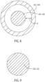
- FIG. 8 is a cross-sectional view of the dispensed first and second liquids 120, 122 and taken along line A-A of FIG. 7 .
- FIG. 9 is a cross-sectional view of the dispensed first and second liquids 120, 122 and taken along line B-B of FIG. 7 .
- the first liquid 120 and the second liquid 122 are not mixed as they exit the dispensing assembly 102. Rather, the first liquid 120 and the second liquid 122 are separate and independent of one another when initially dispensed from the dispensing assembly 102.
- a gap G can be defined between the inside diameter of the second liquid stream 240 and the outside diameter of the first liquid stream 164. While FIGS. 7 and 8 depict a gap between the first liquid stream 164 and the second liquid stream 240, in some examples a gap may not necessarily be discernible between each of the two liquids.
- the first and second liquid streams 164, 240 can converge with distance away from the dispensing assembly 102, such as at a location outside of the dispensing assembly 102 and downstream of the first and second outlets 130, 132.
- the second fluid stream can converge on itself downstream of the first and second outlets 130, 132. More particularly, the tapering shape of the sidewall 208 of the second element 142 and/or the cylindrical wall 160 of the first element 140 can direct the second liquid stream 240 inwardly onto itself. As the second fluid stream converges on itself, the second fluid stream intersects the first fluid stream causing the two independent liquids to mix or reconstitute.
- the first and second liquid streams 164, 240 can converge into a heterogeneous but single liquid stream (see FIG. 9 ).
- the first and second liquid streams 164, 240 can converge between 1 and 10 millimeters away from the dispensing assembly 102, such as between 1 and 3 millimeters below the bottom surface 206 of the second element 142. Convergence of the first and second liquid streams 164, 240 closely adjacent to the bottom of the dispensing assembly 102 can allow for a longer mixing time before the resultant beverage enter the container 104.
- the first and second liquid streams 164, 240 can mix while still in contact with the exit surfaces of the dispensing assembly 102 to limit potential fouling of the dispensing assembly 102. Due to the shape of the dispensing assembly 102, the first and second liquid streams 164, 240 can converge at a location spaced differently from the first and second outlets 130, 132. For example, the first and second liquid streams 164, 240 can converge at a location spaced at a first distance from the first outlet 130, the converging location also spaced at a second distance from the second outlet 132. Due to the protruding aspect of the tube 162 or cylindrical wall 160 of the first element 140 through the second outlet 132, the second distance can be greater than the first distance.
- the first liquid 120 and the second liquid 122 intersect and mix after they are dispensed from the appliance 100.
- the mixing occurs in an ambient environment outside of the appliance 100.
- This configuration limits bacterial growth within the dispensing assembly 102.
- This configuration can also allow the appliance 100 to dispense a beverage with desired properties.
- the second liquid 122 can be a carbonated liquid. Due to the carbonation in the liquid, the flow rate and/or the mixing of the first liquid 120 and/or the second liquid 122 can be adjusted or controlled to limit agitation of the carbonated second liquid 122. For instance, the degree of mixing can be controlled to limit the carbonation from being so agitated during mixing that the carbonation leaves the second liquid 122.
- the flow rate of the first liquid 120 and/or the second liquid 122 can be between 0.5 liters per minute and 1.5 liters per minute. In some examples, the flow rate can be between 0.75 liters per minute and 1.25 liters per minute. In some examples, the collective flow rate of both the first and second liquids 120, 122 can be about 1.0 liter per minute.
- the diameter of the second fluid stream can be appropriately sized to achieve a desired convergence or mixing characteristic.
- the diameter of the second fluid stream adjacent to the second outlet 132 can be between 8.5 millimeters and 9.0 millimeters.
- An annular liquid column with a diameter less than 8.5 millimeters can cause the mixing to be too turbulent between the first and second liquids 120, 122, which can disrupt the bonds in the carbon dioxide molecules resulting in less carbonation in the resulting beverage.
- An annular liquid column with a diameter larger than 9.0 millimeters can not maintain the integrity of the annular liquid column, thereby reducing the effectiveness of the mixing.
- annular liquid column with a diameter larger than 9.0 millimeters can result in a second fluid stream that does not completely annularly surround the first liquid stream 164.
- the annular liquid column is compromised, the first liquid 120 is not fully contained or bracketed within the second fluid stream, thereby risking incomplete mixing of the fluids and/or exposure to the first liquid 120.
- Exposure to the first liquid 120 can result in splattering of the first liquid 120 outside of the dispensing area 106, which can be undesirable in embodiments where the first liquid 120 is a syrup.
- the configuration of the dispensing assembly 102 can limit bacterial growth.
- the tube 162 of the first element 140 can be flooded with the second liquid 122 to rinse the first liquid 120 from the tube 162.
- the first liquid 120 is a syrup or other flavoring medium with ingredients prone to cause bacterial growth, such as high concentrations of sugar.
- the second liquid 122 can be applied at different fluid pressures depending on the operation state of the appliance 100. For instance, during normal dispensing operations, the second liquid 122 can be applied at a dispensing pressure. The dispensing pressure can be insufficient to raise the level of the second liquid 122 within the second fluid chamber to the one or more apertures 190 defined through the cylindrical wall 160 of the first element 140. As such, when the second fluid is applied at the dispensing pressure, the second fluid is limited to flowing through the second outlet 132 only.
- the second liquid 122 can be applied at a cleaning pressure greater than the dispensing pressure. Unlike the dispensing pressure, the cleaning pressure can be sufficient to raise the level of the second liquid 122 within the second fluid chamber such that at least a portion of the second fluid flows through the one or more apertures 190 defined in the cylindrical wall 160 or tube 162 of the first element 140. In this manner, the second liquid 122 can pass through both the first and second outlets 130, 132. When flow of the first liquid 120 through the first outlet 130 is stopped, the second fluid can continue to flow through the one or more apertures 190 and out the first outlet 130 to flush the dispensing assembly 102 of the first liquid 120.
- FIG. 10 is a flowchart illustrating an example method 400 of dispensing a beverage.
- the method 400 can include directing or dispensing the first fluid out of the first outlet 130 (Block 402) and directing or dispensing the second fluid out of the second outlet 132 (Block 404).
- the first outlet 130 can be located at the dispensing end 210 of the tube 162.
- the second outlet 132 can be formed, at least in part, by the exterior surface 180 of the tube 162.
- Directing the first fluid out of the first outlet 130 can include forming the internal, first fluid stream as the first fluid exits the first outlet 130.
- Directing the second fluid out of the second outlet 132 can include forming the annular, second liquid stream 240 that surrounds the first liquid stream 164 as the second fluid exits the second outlet 132.
- FIG. 11 is a flowchart illustrating another exemplary method 500 of dispensing a beverage.
- the method 500 can include directing or dispensing the first fluid out of the first outlet 130 (Block 502) and directing or dispensing the second fluid out of the second outlet 132 (Block 504).
- the first outlet 130 can be located at the dispensing end 210 of the tube 162.
- the second outlet 132 can be formed, at least in part, by the exterior surface 180 of the tube 162. Directing the first fluid out of the first outlet 130 can include forming the internal, first fluid stream as the first fluid exits the first outlet 130.
- Directing the second fluid out of the second outlet 132 can include forming the annular, second liquid stream 240 that surrounds the first liquid stream 164 as the second fluid exits the second outlet 132.
- the method 500 can include flooding the tube 162 with the second liquid 122 (Block 506).
- the tube 162 can be flooded with the second liquid 122, increasing a fluid pressure of the second liquid 122. Flooding the tube 162 with the second liquid 122 can cause the second liquid 122 to reach a level at which the second liquid 122 enters the tube 162.
- the level of the second liquid 122 can be raised such that at least a portion of the second liquid 122 passes through the one or more apertures 190 defined in the tube 162, at which point the second liquid 122 exits the first outlet 130, as explained above.
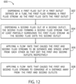
- FIG. 12 is a flowchart illustrating another exemplary method 600 of dispensing a beverage.
- the method 600 can include directing or dispensing the first fluid out of the first outlet 130 (Block 602) and directing or dispensing the second fluid out of the second outlet 132 can include forming the annular, second liquid stream 240 that surrounds the first liquid stream 164 as the second fluid exits the second outlet 132.
- the method 600 can include applying a flow rate that causes the first and second fluid streams to be separate and spaced apart from each other as they exit the first and second outlets 130, 132, respectively (Block 606).
- the method 600 can include applying a flow rate that causes the first and second fluid streams to converge at a distance away from the first and second outlets 130, 132 (Block 608).
- the dispensing assembly 102 can be formed from a variety of materials and means.
- portions of the dispensing assembly 102 can be formed from a thermoplastic material (self-reinforced or fiber reinforced), HDPE, ABS, polycarbonate, polypropylene, polystyrene, PVC, polyamide, and/or PTFE, among others.
- the dispensing assembly 102 can be formed from aluminum or other similar metal.
- the dispensing assembly 102 can be coated with various surface treatments, such as a hydrophobic coating. The materials and/or surface treatments can be food grade.
- the dispensing assembly 102 can be formed or molded in any suitable manner, such as by plug molding, blow molding, injection molding, casting, or the like.
Landscapes
- Devices For Dispensing Beverages (AREA)
Description
- The technology disclosed herein relates generally to beverage dispensers, and more particularly to structures and techniques for combining independent beverage flows.
- Liquid dispensers are appliances that prepare drinks for users. Often, a dispenser will include a connection to a water source, such as the plumbing of a building or an independent water reservoir, and a receiver that receives a package containing a flavoring agent. The water and the flavoring agent are mixed in the appliance before being dispensed from the appliance into the user's cup.
- While many traditional systems utilized a premix method to mix the flavoring agent and water prior to dispensing, this often results in a less sterile system because the premixed solution travels through parts of the system prior to dispensing, which internal parts of the system are often difficult to clean an sterilize. Consequently, a number of systems focus on postmix processes, wherein the flavoring agent and water are combined outside of the system to prevent the internal contamination issues associated with premixing.
- Postmix processes have historically combined the flavoring agent and water immediately before delivery into a cup, or concurrently as independent streams of water and flavoring agent into the cup, allowing mixing to occur in the cup. The latter option, providing independent streams of water and flavoring agent to be mixed in a cup, suffers from a number of issues including possible incomplete mixing due to insufficient pressures, turbulence, or material properties that resist easy mixing. Additionally, the sequential dispensing of independent streams is also more time consuming, noisy, and can offer a less satisfactory user experience. In contrast, combining the flavoring agent and water immediately before delivery into a cup presents additional challenges. This in-air mixing relies on precise timing and accurate flow paths to ensure consistent mixing and to ensure accurate dispensing into the desired cup and avoiding an undesirable spill.
- One example traditional liquid dispenser is disclosed in
US 6 401 197 B1 issued to Jerome L. Elkind. In this reference, a dispenser is taught, including a plurality of beverage supply sources adapted to supply a plurality of beverage constituents. The beverage mixing apparatus includes a first aperture adapted to receive the plurality of beverage constituents, a second aperture adapted to dispense a mixture of the beverage constituents, and a conduit interposed between the first and second apertures and adapted to mix the plurality of beverage constituents. A dispensing nozzle is engaged with the second aperture, and a sensor device is disposed along the conduit, proximal to the second aperture, which is adapted to adjust the supply of a beverage constituent. Other dispensers are disclose inUS 3 217 931 A ,US 3 643 688 A ,US 9 272 817 B2 JP 2013 014338 A claim 1 in that it lacks apertures in the cylindrical wall of the inner tube. - The invention relates to a dispensing assembly according to
claim 1 and a method for dispensing a beverage according toclaim 6. - One or more apertures can be defined through the cylindrical wall of the first element. The cylindrical wall can separate the first and second liquids. In this regard, the one or more apertures are arranged to limit passage of the second fluid toward the first outlet when the second fluid exhibits a dispensing pressure. The one or more apertures can be further arranged to allow passage of the second fluid toward the second outlet when the second fluid exhibits a cleaning pressure that is greater than the dispensing pressure.
- The wall extends beyond a lowermost bottom surface of the annular wall. In this regard, the internal wall can taper toward the first outlet. The dispensing assembly can further include one or more apertures defined through the internal wall to selectively connect the first and second liquid chambers. In this regard, the one or more apertures can be arranged for, at a first cleaning pressure, flow of the second liquid toward the first outlet. Further, the one or more apertures can be arranged for, at a second dispensing pressure that is less than the first cleaning pressure, restriction of the second liquid toward the first outlet.
- In another embodiment, the internal liquid stream and the annular liquid column converge at a location downstream of both the first outlet and the second outlet. In some cases, the location can be spaced at a first distance from the first outlet, and the location is spaced at a second distance from the second outlet. As such, the second distance can be greater than the first distance.
- In an embodiment, the The first liquid can include a flavoring medium. The second liquid can include a carbonated liquid. In some cases, the method can further include applying a flow rate that causes the internal fluid stream and the annular liquid column to converge at a distance away from the first outlet and the second outlet.
- This Summary is provided to introduce a selection of concepts in a simplified form that are further described below in the Detailed Description. This Summary is not intended to identify key features or essential features of the claimed subject matter, nor is it intended to be used to limit the scope of the claimed subject matter. A more extensive presentation of features, details, utilities, and advantages of the present disclosure as defined in the claims is provided in the following written description of various embodiments of the claimed subject matter and illustrated in the accompanying drawings.
-
-
FIG. 1 is a schematic representation of an appliance in accordance with aspects of the present disclosure. -
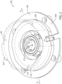
FIG. 2 is a top isometric view of a dispensing assembly in accordance with aspects of the present disclosure. -
FIG. 3 is an exploded view of the dispensing assembly ofFIG.2 . -
FIG. 4 is a cross-sectional view of the dispensing assembly ofFIG. 2 taken along line 4-4 ofFIG. 2 . -
FIG. 5 is a bottom isometric view of an additional dispensing assembly in accordance with aspects of the present disclosure -
FIG. 6 is a cross-sectional view of the dispensing assembly ofFIG. 5 taken along line 6-6 ofFIG. 5 . -
FIG. 7 is a schematic cross-sectional view of an example dispensing operation combining first and second liquids in accordance with aspects of the present disclosure. -
FIG. 8 is a cross-sectional view of the dispensing operation and taken along line 8-8 inFIG. 7 . -
FIG. 9 is a cross-sectional view of the dispensing operation and taken along line 9-9 inFIG. 7 . -
FIG. 10 is a flowchart illustrating an example method of dispensing a beverage in accordance with aspects of the present disclosure. -
FIG. 11 is a flowchart illustrating another exemplary method of dispensing a beverage in accordance with aspects of the present disclosure. -
FIG. 12 is a flowchart illustrating another exemplary method of dispensing a beverage in accordance with aspects of the present disclosure. - The use of cross-hatching or shading in the accompanying figures is generally provided to clarify the boundaries between adjacent elements and also to facilitate legibility of the figures. Accordingly, neither the presence nor the absence of cross-hatching or shading conveys or indicates any preference or requirement for particular materials, material properties, element proportions, element dimensions, commonalities of similarly illustrated elements, or any other characteristic, attribute, or property for any element illustrated in the accompanying figures.
- Additionally, it should be understood that the proportions and dimensions (either relative or absolute) of the various features and elements (and collections and groupings thereof) and the boundaries, separations, and positional relationships presented therebetween, are provided in the accompanying figures merely to facilitate an understanding of the various embodiments described herein and, accordingly, can not necessarily be presented or illustrated to scale, and are not intended to indicate any preference or requirement for an illustrated embodiment to the exclusion of embodiments described with reference thereto.
- An appliance can be used to prepare beverages. In some examples, the appliance is a brewing machine that prepares beverages like coffee, tea, hot chocolate, cider, and the like. In other examples, the appliance is a machine used to mix the ingredients for carbonated drinks, fruit drinks, milk products, alcoholic drinks, other types of drinks, or combinations thereof.
- The appliance can include a dispenser that is in communication with a first liquid chamber and a second liquid chamber. The first liquid chamber and the second liquid chamber can include different types of liquids, or constituents of the desired final beverage. For example, one of the liquid chambers can contain water, carbonated water, milk, or another type of base liquid, while the other chamber includes a flavoring agent. The flavoring agent can include a concentrate, a syrup, a supplement, a dye, another type of flavoring agent, or combinations thereof. These different types of liquids can be separated from each other before the user instructs the appliance to dispense the beverage.
- In response to user instructions to dispense the beverage, liquid from each of the first liquid chamber and the second liquid chamber is dispensed out of the appliance simultaneously. The first liquid is dispensed out of a first outlet, and the second liquid is dispensed out of a second outlet.
- The first outlet is incorporated into a tube that is in fluid communication with a first liquid chamber. The tube includes a chamber end that receives the first liquid. A dispensing end of the tube is opposite of the chamber end, and the first outlet is defined in the dispensing end. As the first liquid exits the dispensing end of the tube, the first liquid forms a liquid stream that is directed to a container, such as a cup.
- The second outlet can be formed by a wall that directs the second liquid towards the outside exterior of the tube. An opening in the wall can collectively form a second outlet with the exterior side of the tube. Thus, the dispensing end of the tube can protrude beyond the second outlet. As a result, the second outlet forms a ring-like shape through which the second liquid is dispensed. As the second liquid exits the appliance through the second outlet, the second liquid forms an annular liquid column that surrounds the internal liquid stream of the first liquid.
- With the internal fluid stream surrounded by the annular fluid column, the internal fluid stream can not be visible to an observer looking in from the outside because the internal liquid stream is obscured by the annular liquid column. Initially, as the liquid stream and the annular liquid column exit from the dispenser, a gap can exist between them. As the distance from the dispenser increases, the annular liquid column can converge on itself. The annular liquid column can converge towards a central region as the liquids progressively move away from the dispenser until the annular liquid column intersects the internal liquid stream. The interaction between the internal liquid stream and the annular liquid column causes the two liquids to mix in the air within the ambient environment outside of the appliance.
- By mixing the first liquid and the second liquid outside the appliance, the appliance can be simplified without needing a mixing chamber. This simplifies the construction and lowers the cost of the appliance. Another advantage of mixing the first liquid and the second liquid outside of the appliance is an ability to control the amount of turbulence between the two liquids as they mix. In cases where the second liquid includes carbonation, mixing the two liquids together can result in the carbonation forming bubbles during mixing that causes the carbonation to exit the liquids before the liquids enter into a user's cup. With the system described in this disclosure, the amount of turbulence can be controlled by varying the flow rate of the first and second liquids. By controlling the flow rates, and therefore the degree of turbulence during mixing, the carbonation can be preserved within the liquids.
- Reference will now be made to the accompanying drawings, which assist in illustrating various features of the present disclosure. The following description is presented for purposes of illustration and description. Furthermore, the description is not intended to limit the inventive aspects to the forms disclosed herein. Consequently, variations and modifications commensurate with the following teachings, and skill and knowledge of the relevant art, are within the scope of the present inventive aspects.
-
FIG. 1 depicts an example of anappliance 100 that is used to make beverages, such as the appliances discussed above and described in greater detail below. Theappliance 100 can include a dispensingassembly 102 operable to dispense a beverage. In one example, the dispensingassembly 102 can dispense a beverage into acontainer 104, such as a cup, a mug, a bottle, or the like. Depending the particular application, theappliance 100 can include adispensing area 106, such as a cavity or recess defined within theappliance 100 adjacent to the dispensingassembly 102. In such examples, thecontainer 104 can be positioned within the dispensingarea 106 to dispense the beverage into thecontainer 104. For example, thecontainer 104 can be positioned on ashelf 108 defined below the dispensingassembly 102. In some examples, the dispensingassembly 102 can be movable relative to theappliance 100. For instance, the dispensingassembly 102 can be extendable from theappliance 100 to facilitate dispensing of a beverage into thecontainer 104. Such a configuration can allow dispensing of a beverage into acontainer 104 sized larger than the dispensingarea 106, into acontainer 104 positioned remotely from theappliance 100, or the like. - The
appliance 100 can be operable to dispense many beverages. Examples include coffee, tea, hot chocolate, cider, milk products, fruit drinks, soft drinks, alcoholic drinks, carbonated drinks, or the like, or any combination thereof. In particular, theappliance 100 is arranged to mix two or more ingredients together, such as reconstituting two or more independent beverage flows to make a desired beverage. In one example, theappliance 100 is operable to mix a first liquid 120 with asecond liquid 122. As described more fully below, the first andsecond liquids 120, 122 can be mixed at a position external to the appliance, such as at a position between the dispensingassembly 102 and thecontainer 104. - Depending on the particular application, the first liquid 120 can be a flavoring medium or concentrate, such as concentrated syrup or other ingredients. In some examples, the first liquid 120 can include concentrated alcohol, coloring dyes, flavor, or the like, or any combination thereof. The
second liquid 122 can be added to dilute the first liquid 120 to a desired concentration. For example, thesecond liquid 122 can be water, carbonated liquid, alcohol, or milk, among others, or any combination thereof. Combining the first andsecond liquids 120, 122 can provide a desired characteristic of the resultant beverage. For instance, reconstituting the first andsecond liquids 120, 122 can provide a desired flavor, texture, look, and/or smell of the beverage. - The
appliance 100 can include many configurations to facilitate reconstitution of the first andsecond liquids 120, 122. In some examples, theappliance 100 can include a pod receiver 124 (seeFIG. 2 ) that holds a pod containing a beverage medium. The beverage medium can include ingredients used to make a certain type of beverage. In some cases, the beverage medium is the first liquid 120 or a constituent of the first liquid 120. The pod can be placed into thepod receiver 124 when the user desires to prepare a beverage. Theappliance 100 can use the contents of the pod to make a drink. For example, the pod can be punctured or otherwise opened within thepod receiver 124 to empty its contents into thepod receiver 124 for subsequent mixing with thesecond liquid 122. In other examples, the beverage medium can be poured directly or indirectly into the appliance, such as into a first fluid reservoir. - The
second liquid 122 can be supplied to theappliance 100 in many ways. In one example, thesecond liquid 122 can be supplied to theappliance 100 by a user who can add thesecond liquid 122 into a second fluid reservoir of theappliance 100. In some cases, thesecond liquid 122 can be supplied to theappliance 100 through a plumbing connection, such as from a dedicated water supply of a building. In other examples, thesecond liquid 122 can be supplied from other sources. In some cases, thesecond liquid 122 is carbonated. In such examples, a carbonation canister can be attached to theappliance 100 to deliver carbon dioxide gas to thesecond liquid 122. Depending on the particular application, the carbonation can be added to thesecond liquid 122 prior to dispensing thesecond liquid 122 into thecontainer 104. In alternative examples, thesecond liquid 122 can be pre-mixed with the carbonation and supplied to the appliance in the premixed state.Carbon dioxide, nitrogen, or another type of gas can be added to thesecond liquid 122 prior to dispensing thesecond liquid 122 into thecontainer 104. In alternative examples, thesecond liquid 122 can be pre-mixed with the carbonation and supplied to the appliance in the premixed state. Carbon dioxide, nitrogen, or another type of gas can be added to the first liquid 120 and/or thesecond liquid 122, such as inside theappliance 100 or prior to adding the liquids to theappliance 100. -
FIG. 2 is an isometric view of the dispensingassembly 102.FIG. 3 is an exploded view of the dispensingassembly 102.FIG. 4 is a cross-sectional view of the dispensingassembly 102 taken along line 4-4 ofFIG. 2 . Referring toFIGS. 2-4 , the dispensingassembly 102, which can be referred to as a dispensing apparatus, can be arranged to dispense the first andsecond liquids 120, 122 simultaneously or near simultaneously. As shown inFIG. 4 , the dispensing assembly can include afirst outlet 130 and asecond outlet 132. Thefirst outlet 130 can be in fluid communication with a firstliquid chamber 134. The first liquid 120 can pass through the firstliquid chamber 134 to be dispensed through thefirst outlet 130. Thesecond outlet 132 can be in fluid communication with a secondliquid chamber 136. Thesecond liquid 122 can pass through the secondliquid chamber 136 to be dispensed through thesecond outlet 132. - The first and second
liquid chambers second outlets assembly 102 can include first andsecond elements liquid chambers second outlets FIG. 4 , the first andsecond elements liquid chambers assembly 102. Additionally or alternatively, the internal wall 150 can at least partially define the first andsecond outlets - The
first element 140, which can be considered an inner or upper element, defines thefirst outlet 130 through which the first liquid 120 is dispensed. Referring toFIGS. 3 and4 , thefirst element 140 includes a cylindrical wall 160 defining atube 162 through which the first liquid 120 passes to thefirst outlet 130. In such examples, the first liquid 120 forms a first liquid stream 164 when dispensed through thefirst outlet 130. Thetube 162 at least partially defines the firstliquid chamber 134. The cylindrical wall 160 extends from atop wall 170 of thefirst element 140. - In such examples, an
aperture 172 can be defined through thetop wall 170, theaperture 172 being in fluid communication with the firstliquid chamber 134. The cylindrical wall 160 of thefirst element 140 can at least partially define the internal wall 150 separating the first and secondliquid chambers second outlets annular flange 174 can extend from thetop wall 170. Theannular flange 174 andtop wall 170 can define thepod receiver 124 arranged to hold a beverage pod. As shown, theannular flange 174 can extend in a direction opposite the cylindrical wall 160. Theannular flange 174 can be concentrically aligned with the cylindrical wall 160, though other relationships are contemplated. In some examples, thefirst element 140 can include apost 126 arranged to pierce or puncture the pod such that the pod's contents are emptied into thepod receiver 124 and/or thetube 162 for subsequent dispensing through thefirst outlet 130. As shown, thepost 126 can be in fluid communication with thetube 162, such as positioned above and concentrically aligned with thetube 162. In some examples, thefirst element 140 can include aseal 176 extending from or positioned adjacent to thetop wall 170. Theseal 176 can annularly surround at least a portion of the cylindrical wall 160. Theseal 176 can be structure defined as part of thefirst element 140, or can be an O-ring or other sealing apparatus. - The cylindrical wall 160 of the
first element 140 can include many configurations. As shown, the cylindrical wall 160 can include a circular cross-section, though other shapes are contemplated, including polygonal or elliptical, among others. The cylindrical wall 160 can include anexterior surface 180 and aninterior surface 182. In such examples, theinterior surface 182 of the cylindrical wall 160 can define a diameter D1 of thefirst outlet 130. - Depending on the particular application, the diameter D1 of the
first outlet 130 can be between 2 and 8 millimeters. The diameter D1 of thefirst outlet 130 can be sized to provide a consistent water cone formation. The diameter D1 of thefirst outlet 130 can also be sized to limit the potential of the first liquid 120 fouling the exit surfaces of thefirst outlet 130 before the first liquid 120 exits thefirst outlet 130 and mixes with thesecond liquid 122. The cylindrical wall 160 can include a uniform or substantially uniform thickness such that the exterior andinterior surfaces top wall 170. In one example, the cylindrical wall 160 can taper in diameter to thefirst outlet 130. In such examples, the cylindrical wall 160 can define a nozzle shaping the flow of the first liquid 120 through thefirst outlet 130. - In one example, one or
more apertures 190 can be defined through the cylindrical wall 160. In such examples, the one ormore apertures 190 can connect theexterior surface 180 of the cylindrical wall 160 ortube 162 with theinterior surface 182 of the cylindrical wall 160 ortube 162. The one ormore apertures 190 can be spaced at a distance away from thefirst outlet 130. For example, the one ormore apertures 190 can be defined adjacent to thetop wall 170 of thefirst element 140. In some examples, the one ormore apertures 190 can be defined above thesecond outlet 132 of the dispensingassembly 102. As explained more fully below, the one ormore apertures 190 can selectively connect the first and secondliquid chambers second liquid 122 can selectively pass through the one ormore apertures 190 to be dispensed through thefirst outlet 130 for the purposes explained below. - With continued reference to
FIGS. 2-4 , thesecond element 142, which can be considered an outer or lower element, defines thesecond outlet 132 through which thesecond liquid 122 is dispensed. Thesecond element 142 includes anannular wall 200 with anopening 202 therethrough to define thesecond outlet 132. Theannular wall 200 includes atop shelf 204 and abottom surface 206. Asidewall 208 extends between thetop shelf 204 and thebottom surface 206 to define theopening 202. Thesidewall 208 is sloped such that theopening 202 tapers in diameter to thesecond outlet 132. Thesidewall 208 defines a diameter D2 of thesecond outlet 132. The diameter D2 of thesecond outlet 132 is greater than the diameter D1 of thefirst outlet 130. Depending on the particular application, the diameter D2 of thesecond outlet 132 is between 7.0 and 10.5 millimeters, such as between 8.5 and 9.0 millimeters. As shown inFIG. 4 , the cylindrical wall 160 of thefirst element 140 extends beyond thebottom surface 206 of thesecond element 142. For example, a dispensingend 210 of the cylindrical wall 160 protrudes between 3.0 and 5.0 millimeters beyond or below thebottom surface 206 of thesecond element 142. - The
second element 142 can include aflange 220 extending from thetop shelf 204 for connection with thefirst element 140. For instance, theflange 220 of thesecond element 142 can abut thetop wall 170 of thefirst element 140 when the first andsecond elements second elements seal 176 of thefirst element 140 can sealingly engage theflange 220 of thesecond element 142. The engagement between theseal 176 and theflange 220 can seal the secondliquid chamber 136. The engagement between theseal 176 and theflange 220 can frictionally hold the first andsecond elements first element 140 is removable from thesecond element 142. In such examples, thefirst element 140 can be removed for cleaning, replacement, etc. In other examples, the first andsecond elements assembly 102. - As shown in at least
FIG. 3 , thesecond element 142 can include one ormore ports 230. In such examples, thesecond liquid 122 can be pumped through the one ormore ports 230 for dispensing through thesecond outlet 132. In one example, thesecond liquid 122 can pass through the one ormore ports 230 and discharged onto thetop shelf 204 of the second element 142 (seeFIG. 4 ). In such examples, thesecond liquid 122 can flow inwardly from thetop shelf 204 and down thesidewall 208 of thesecond element 142 to form a secondliquid stream 240 out thesecond outlet 132. Depending on the particular application, the flow of thesecond liquid 122 can be laminar along thetop shelf 204 andsidewall 208. As described more fully below, the flow of thesecond liquid 122 can be limited such that the secondliquid stream 240 forms an annular liquid column or ring when dispensed through thesecond outlet 132. Additionally or alternatively, thesecond liquid 122 can contact theexterior surface 180 of the cylindrical wall 160 of thefirst element 140 to define the annular liquid column. For instance, thesecond liquid 122 can contact thesidewall 208 of thesecond element 142 as well as theexterior surface 180 of the cylindrical wall 160 of thefirst element 140 to define a ring shape of the secondliquid stream 240. In this manner, the cylindrical wall 160 of thefirst element 140 can be positioned at least partially within thesecond outlet 132 of thesecond element 142. In such examples, at least a portion of theexterior surface 180 of the cylindrical wall 160 ortube 162 can be disposed within thesecond outlet 132. As explained below, the secondliquid stream 240 can annularly surround the first liquid stream 164 when the first andsecond liquids 120, 122 are first dispensed through the first andsecond outlets -
FIG. 5 is an isometric view of anadditional dispensing assembly 302 in accordance with aspects of the present disclosure.FIG. 6 is a cross-sectional view of the dispensingassembly 302 ofFIG. 5 taken along line 6-6 ofFIG. 5 . In general, the dispensingassembly 302 is similar to the dispensingassembly 102 and its associated described above and thus, in certain instances, descriptions of like features will not be discussed when they would be apparent to those with skill in the art in light of the description above and in view ofFIGS. 5 and6 . As such, any description above or below with reference to the dispensingassembly 102 can apply to the dispensingassembly 302, or vice versa. For ease of reference, like structure is represented with similar reference numbers. - Referring to
FIGS. 5 and6 , theannular flange 174 of the dispensingassembly 302 can be arranged for connection with theflange 220 of thesecond element 142. For example, theflange 220 of thesecond element 142 can define aseat 322 in which theannular flange 174 of thefirst element 140 is seated when the first andsecond elements flanges second elements second elements annular flange 174 of thefirst element 140 can be positioned about theflange 220 of thesecond element 142 for connection thereto. The engagement between theflanges liquid chamber 136. Depending on the particular application, theflanges second elements flanges second elements first element 140 is removable from thesecond element 142. In such examples, thefirst element 140 can be removed for cleaning, replacement, etc. In other examples, theflanges assembly 102. -
FIG. 7 depicts an example of the first liquid stream 164 and the secondliquid stream 240 converging after each is individually dispensed from the dispensingassembly 102.FIG. 8 is a cross-sectional view of the dispensed first andsecond liquids 120, 122 and taken along line A-A ofFIG. 7 .FIG. 9 is a cross-sectional view of the dispensed first andsecond liquids 120, 122 and taken along line B-B ofFIG. 7 . Referring toFIGS. 7 and8 , the first liquid 120 and thesecond liquid 122 are not mixed as they exit the dispensingassembly 102. Rather, the first liquid 120 and thesecond liquid 122 are separate and independent of one another when initially dispensed from the dispensingassembly 102. For example, a gap G can be defined between the inside diameter of the secondliquid stream 240 and the outside diameter of the first liquid stream 164. WhileFIGS. 7 and8 depict a gap between the first liquid stream 164 and the secondliquid stream 240, in some examples a gap may not necessarily be discernible between each of the two liquids. - Referring to
FIGS. 7 and9 , the first and second liquid streams 164, 240 can converge with distance away from the dispensingassembly 102, such as at a location outside of the dispensingassembly 102 and downstream of the first andsecond outlets second outlets sidewall 208 of thesecond element 142 and/or the cylindrical wall 160 of thefirst element 140 can direct the secondliquid stream 240 inwardly onto itself. As the second fluid stream converges on itself, the second fluid stream intersects the first fluid stream causing the two independent liquids to mix or reconstitute. In one example, the first and second liquid streams 164, 240 can converge into a heterogeneous but single liquid stream (seeFIG. 9 ). Depending on the particular application, the first and second liquid streams 164, 240 can converge between 1 and 10 millimeters away from the dispensingassembly 102, such as between 1 and 3 millimeters below thebottom surface 206 of thesecond element 142. Convergence of the first and second liquid streams 164, 240 closely adjacent to the bottom of the dispensingassembly 102 can allow for a longer mixing time before the resultant beverage enter thecontainer 104. However, it may not be desirable for the first and second liquid streams 164, 240 to mix while still in contact with the exit surfaces of the dispensingassembly 102 to limit potential fouling of the dispensingassembly 102. Due to the shape of the dispensingassembly 102, the first and second liquid streams 164, 240 can converge at a location spaced differently from the first andsecond outlets first outlet 130, the converging location also spaced at a second distance from thesecond outlet 132. Due to the protruding aspect of thetube 162 or cylindrical wall 160 of thefirst element 140 through thesecond outlet 132, the second distance can be greater than the first distance. - As noted above, the first liquid 120 and the
second liquid 122 intersect and mix after they are dispensed from theappliance 100. Thus, the mixing occurs in an ambient environment outside of theappliance 100. This configuration limits bacterial growth within the dispensingassembly 102. This configuration can also allow theappliance 100 to dispense a beverage with desired properties. For example, as noted above, thesecond liquid 122 can be a carbonated liquid. Due to the carbonation in the liquid, the flow rate and/or the mixing of the first liquid 120 and/or thesecond liquid 122 can be adjusted or controlled to limit agitation of the carbonatedsecond liquid 122. For instance, the degree of mixing can be controlled to limit the carbonation from being so agitated during mixing that the carbonation leaves thesecond liquid 122. To control the level of turbulence when mixing, the flow rate of the first liquid 120 and/or thesecond liquid 122 can be between 0.5 liters per minute and 1.5 liters per minute. In some examples, the flow rate can be between 0.75 liters per minute and 1.25 liters per minute. In some examples, the collective flow rate of both the first andsecond liquids 120, 122 can be about 1.0 liter per minute. - Additionally or alternatively, the diameter of the second fluid stream can be appropriately sized to achieve a desired convergence or mixing characteristic. In some examples, the diameter of the second fluid stream adjacent to the
second outlet 132 can be between 8.5 millimeters and 9.0 millimeters. An annular liquid column with a diameter less than 8.5 millimeters can cause the mixing to be too turbulent between the first andsecond liquids 120, 122, which can disrupt the bonds in the carbon dioxide molecules resulting in less carbonation in the resulting beverage. An annular liquid column with a diameter larger than 9.0 millimeters can not maintain the integrity of the annular liquid column, thereby reducing the effectiveness of the mixing. For example, an annular liquid column with a diameter larger than 9.0 millimeters can result in a second fluid stream that does not completely annularly surround the first liquid stream 164. When the annular liquid column is compromised, the first liquid 120 is not fully contained or bracketed within the second fluid stream, thereby risking incomplete mixing of the fluids and/or exposure to the first liquid 120. Exposure to the first liquid 120 can result in splattering of the first liquid 120 outside of the dispensingarea 106, which can be undesirable in embodiments where the first liquid 120 is a syrup. - As noted above, the configuration of the dispensing
assembly 102 can limit bacterial growth. For example, thetube 162 of thefirst element 140 can be flooded with thesecond liquid 122 to rinse the first liquid 120 from thetube 162. Such a configuration can be desirable where the first liquid 120 is a syrup or other flavoring medium with ingredients prone to cause bacterial growth, such as high concentrations of sugar. In one example, thesecond liquid 122 can be applied at different fluid pressures depending on the operation state of theappliance 100. For instance, during normal dispensing operations, thesecond liquid 122 can be applied at a dispensing pressure. The dispensing pressure can be insufficient to raise the level of thesecond liquid 122 within the second fluid chamber to the one ormore apertures 190 defined through the cylindrical wall 160 of thefirst element 140. As such, when the second fluid is applied at the dispensing pressure, the second fluid is limited to flowing through thesecond outlet 132 only. - During a cleaning operation of the
appliance 100, thesecond liquid 122 can be applied at a cleaning pressure greater than the dispensing pressure. Unlike the dispensing pressure, the cleaning pressure can be sufficient to raise the level of thesecond liquid 122 within the second fluid chamber such that at least a portion of the second fluid flows through the one ormore apertures 190 defined in the cylindrical wall 160 ortube 162 of thefirst element 140. In this manner, thesecond liquid 122 can pass through both the first andsecond outlets first outlet 130 is stopped, the second fluid can continue to flow through the one ormore apertures 190 and out thefirst outlet 130 to flush the dispensingassembly 102 of the first liquid 120. -
FIG. 10 is a flowchart illustrating anexample method 400 of dispensing a beverage. Referring toFIG. 10 , themethod 400 can include directing or dispensing the first fluid out of the first outlet 130 (Block 402) and directing or dispensing the second fluid out of the second outlet 132 (Block 404). Thefirst outlet 130 can be located at the dispensingend 210 of thetube 162. Thesecond outlet 132 can be formed, at least in part, by theexterior surface 180 of thetube 162. Directing the first fluid out of thefirst outlet 130 can include forming the internal, first fluid stream as the first fluid exits thefirst outlet 130. Directing the second fluid out of thesecond outlet 132 can include forming the annular, secondliquid stream 240 that surrounds the first liquid stream 164 as the second fluid exits thesecond outlet 132. -
FIG. 11 is a flowchart illustrating anotherexemplary method 500 of dispensing a beverage. Referring toFIG. 11 , themethod 500 can include directing or dispensing the first fluid out of the first outlet 130 (Block 502) and directing or dispensing the second fluid out of the second outlet 132 (Block 504). Thefirst outlet 130 can be located at the dispensingend 210 of thetube 162. Thesecond outlet 132 can be formed, at least in part, by theexterior surface 180 of thetube 162. Directing the first fluid out of thefirst outlet 130 can include forming the internal, first fluid stream as the first fluid exits thefirst outlet 130. Directing the second fluid out of thesecond outlet 132 can include forming the annular, secondliquid stream 240 that surrounds the first liquid stream 164 as the second fluid exits thesecond outlet 132. In some examples, themethod 500 can include flooding thetube 162 with the second liquid 122 (Block 506). Thetube 162 can be flooded with thesecond liquid 122, increasing a fluid pressure of thesecond liquid 122. Flooding thetube 162 with thesecond liquid 122 can cause thesecond liquid 122 to reach a level at which thesecond liquid 122 enters thetube 162. For example, the level of thesecond liquid 122 can be raised such that at least a portion of the second liquid 122 passes through the one ormore apertures 190 defined in thetube 162, at which point thesecond liquid 122 exits thefirst outlet 130, as explained above. -
FIG. 12 is a flowchart illustrating anotherexemplary method 600 of dispensing a beverage. Referring toFIG. 12 , themethod 600 can include directing or dispensing the first fluid out of the first outlet 130 (Block 602) and directing or dispensing the second fluid out of thesecond outlet 132 can include forming the annular, secondliquid stream 240 that surrounds the first liquid stream 164 as the second fluid exits thesecond outlet 132. In some examples, themethod 600 can include applying a flow rate that causes the first and second fluid streams to be separate and spaced apart from each other as they exit the first andsecond outlets method 600 can include applying a flow rate that causes the first and second fluid streams to converge at a distance away from the first andsecond outlets 130, 132 (Block 608). - The dispensing
assembly 102 can be formed from a variety of materials and means. For example, portions of the dispensingassembly 102 can be formed from a thermoplastic material (self-reinforced or fiber reinforced), HDPE, ABS, polycarbonate, polypropylene, polystyrene, PVC, polyamide, and/or PTFE, among others. In some examples, the dispensingassembly 102 can be formed from aluminum or other similar metal. The dispensingassembly 102 can be coated with various surface treatments, such as a hydrophobic coating. The materials and/or surface treatments can be food grade. The dispensingassembly 102 can be formed or molded in any suitable manner, such as by plug molding, blow molding, injection molding, casting, or the like. - The description herein is provided to enable a person skilled in the art to make or use the disclosure. Various modifications to the disclosure will be readily apparent to those skilled in the art, and the generic principles defined herein can be applied to other variations without departing from the scope defined by the claims. Thus, the disclosure is not limited to the examples described herein, but is to be accorded the broadest scope consistent with the claims.
Claims (13)
- A dispensing assembly (102) comprising:a first element (140) defining a first outlet (130) through which a first liquid (120) is dispensed, the first element including a cylindrical wall (160) defining a tube (162) through which the first liquid passes to the first outlet; anda second element (142) defining a second outlet (132) through which a second liquid (122) is dispensed, wherein one or more apertures (172) are apertures are defined through the cylindrical wall of the first element, the cylindrical wall separating the first and second liquids; andwherein:the first liquid forms an internal liquid stream (164) when dispensed through the first outlet;
the second liquid forms an annular liquid column around the internal liquid stream when dispensed through the second outlet;the first outlet is configured to form the internal liquid stream as being concentric with the annular liquid column; andthe cylindrical wall of the first element is positioned at least partially within the second outlet of the second element and extends beyond a bottom surface of the second element. - The dispensing assembly (102) of claim 1, wherein the one or more apertures (172) are arranged to:limit passage of the second fluid (122) toward the first outlet (130) when the second fluid exhibits a dispensing pressure; andallow passage of the second fluid toward the second outlet (132) when the second fluid exhibits a cleaning pressure that is greater than the dispensing pressure.
- The dispensing assembly of claim 1, wherein the cylindrical wall (160) tapers toward the first outlet (130).
- The dispensing assembly (102) of claim 1, wherein the internal liquid stream (164) and the annular liquid column converge at a location downstream of both the first outlet (130) and the second outlets (132).
- The dispensing assembly (102) of claim 4, wherein the location is spaced at a first distance from the first outlet (130), and the location is spaced at a second distance from the second outlet (132), wherein the second distance is greater than the first distance.
- A method of dispensing a beverage, comprising:directing a first liquid (120) out of a first outlet (130), the first outlet located at a dispensing end of a tube (162), the first liquid (120) forming an internal fluid stream extending along a straight path as the first liquid exits the first outlet;directing a second liquid (122) out of a second outlet, the second outlet formed at least partially by an exterior surface of the tube, the second liquid forming an annular liquid column that concentrically surrounds the internal fluid stream (164) as the second liquid exits the second outlet (132);wherein the tube protrudes out of the second outlet; andflooding the tube with the second liquid by increasing a fluid pressure of the second liquid.
- The method of claim 6, wherein the first liquid (120) includes a flavoring medium.
- The method of claim 7, wherein the second liquid (122) is a carbonated liquid.
- The method of claim 6, further comprising applying a flow rate that causes the internal fluid stream (164) and the annular liquid column to converge at a distance away from the first outlet (130) and the second outlet (132).
- An appliance (100) for producing a beverage, comprising:a pod receiver (124) configured to hold a pod containing a beverage medium; andthe dispensing assembly (102) of claim 1.
- The appliance (100) of claim 10, wherein the dispensing assembly (102) is operably coupled with the pod receiver (124) and configured to cause a flow of the beverage medium from the pod.
- The appliance (100) of claim 11, wherein the first element (140) comprises a post (126) arranged to pierce or puncture the pod.
- The appliance (100) of claim 12, wherein the post (126) is arranged to release the beverage medium into the tube (162).
Priority Applications (1)
| Application Number | Priority Date | Filing Date | Title |
|---|---|---|---|
| EP23203002.3A EP4279442A3 (en) | 2018-03-22 | 2019-03-22 | Reconstitution of independent beverage flows |
Applications Claiming Priority (2)
| Application Number | Priority Date | Filing Date | Title |
|---|---|---|---|
| US201862646785P | 2018-03-22 | 2018-03-22 | |
| PCT/US2019/023579 WO2019183474A1 (en) | 2018-03-22 | 2019-03-22 | Reconstitution of independent beverage flows |
Related Child Applications (2)
| Application Number | Title | Priority Date | Filing Date |
|---|---|---|---|
| EP23203002.3A Division-Into EP4279442A3 (en) | 2018-03-22 | 2019-03-22 | Reconstitution of independent beverage flows |
| EP23203002.3A Division EP4279442A3 (en) | 2018-03-22 | 2019-03-22 | Reconstitution of independent beverage flows |
Publications (3)
| Publication Number | Publication Date |
|---|---|
| EP3768627A1 EP3768627A1 (en) | 2021-01-27 |
| EP3768627A4 EP3768627A4 (en) | 2021-12-29 |
| EP3768627B1 true EP3768627B1 (en) | 2023-11-29 |
Family
ID=67983420
Family Applications (2)
| Application Number | Title | Priority Date | Filing Date |
|---|---|---|---|
| EP19770724.3A Active EP3768627B1 (en) | 2018-03-22 | 2019-03-22 | Reconstitution of independent beverage flows |
| EP23203002.3A Withdrawn EP4279442A3 (en) | 2018-03-22 | 2019-03-22 | Reconstitution of independent beverage flows |
Family Applications After (1)
| Application Number | Title | Priority Date | Filing Date |
|---|---|---|---|
| EP23203002.3A Withdrawn EP4279442A3 (en) | 2018-03-22 | 2019-03-22 | Reconstitution of independent beverage flows |
Country Status (6)
| Country | Link |
|---|---|
| US (2) | US11053110B2 (en) |
| EP (2) | EP3768627B1 (en) |
| CN (1) | CN112041258A (en) |
| AU (1) | AU2019239302A1 (en) |
| CA (1) | CA3094713A1 (en) |
| WO (1) | WO2019183474A1 (en) |
Families Citing this family (7)
| Publication number | Priority date | Publication date | Assignee | Title |
|---|---|---|---|---|
| US10071851B2 (en) | 2010-07-12 | 2018-09-11 | Robert Bao Vu | Apparatus and products for producing beverages, and methods for making and using same |
| US12185867B2 (en) * | 2015-10-30 | 2025-01-07 | Adrian Rivera | Beverage brewer spray apparatus having accommodation for multiple dispersion members |
| CA3094713A1 (en) * | 2018-03-22 | 2019-09-26 | Bedford Systems Llc | Reconstitution of independent beverage flows |
| GB2576779A (en) | 2018-09-03 | 2020-03-04 | Quantex Patents Ltd | Dispenser systems, in-line dispenser assemblies, methods of using and cleaning same |
| WO2020181139A1 (en) * | 2019-03-05 | 2020-09-10 | Bedford Systems Llc | Spring biased box clip |
| USD982382S1 (en) | 2020-03-20 | 2023-04-04 | Bedford Systems Llc | Nozzle for a beverage machine |
| EP4121359A4 (en) | 2020-03-20 | 2024-04-24 | Bedford Systems LLC | NOZZLE FOR CARBONATED BEVERAGES FOR A DRINKS VENDING MACHINE |
Family Cites Families (69)
| Publication number | Priority date | Publication date | Assignee | Title |
|---|---|---|---|---|
| US27112A (en) * | 1860-02-14 | Stop-cock | ||
| US1261986A (en) * | 1917-04-17 | 1918-04-09 | Frank A White | Dispensing-faucet. |
| US2537119A (en) * | 1945-02-02 | 1951-01-09 | Dole Valve Co | Liquid dispenser for carbonated beverages |
| US3091366A (en) | 1960-07-18 | 1963-05-28 | Thomas A Hutsell | Beer dispenser |
| US3217931A (en) | 1962-07-31 | 1965-11-16 | Colgate Palmolive Co | Multicompartment dispensing of different fluent materials |
| US3455332A (en) * | 1965-10-18 | 1969-07-15 | Cornelius Co | Post-mix valve |
| US3373937A (en) * | 1966-04-11 | 1968-03-19 | Bastian Blessing Co | Carbonated water dispensing nozzle |
| US3396871A (en) * | 1966-07-15 | 1968-08-13 | Mccann S Engineering & Mfg Co | Beverage dispensing unit |
| US3580425A (en) * | 1968-09-26 | 1971-05-25 | Electronic Dispensers Internat | Beverage dispenser |
| DE1904014C3 (en) | 1969-01-28 | 1974-06-20 | Noll Maschinenfabrik Gmbh, 4950 Minden | Device for continuously combining beverage components in an adjustable proportion |
| US3727844A (en) * | 1971-04-30 | 1973-04-17 | Eaton Corp | Dispensing apparatus |
| IT974494B (en) * | 1972-12-06 | 1974-06-20 | Colgate Palmolive Co | APPARATUS AND PROCEDURE FOR FILLING CONTAINERS WITH DETACHABLE WALLS WITH A PLURALITY OF FLUENT MATERIALS, FOR EXAMPLE TOOTHPASTES |
| US5129549A (en) * | 1982-09-07 | 1992-07-14 | Imi Cornelius Inc. | Beverage dispensing valve |
| US4509690A (en) * | 1982-12-06 | 1985-04-09 | The Cornelius Company | Carbonated beverage mixing nozzle for a dispenser |
| US5000351A (en) * | 1986-03-21 | 1991-03-19 | The Coca-Cola Company | Concentrate dispensing system for a post-mix beverage dispenser |
| US4753370A (en) * | 1986-03-21 | 1988-06-28 | The Coca-Cola Company | Tri-mix sugar based dispensing system |
| US4708266A (en) * | 1986-03-21 | 1987-11-24 | The Coca-Cola Company | Concentrate dispensing system for a post-mix beverage dispenser |
| US5033651A (en) * | 1989-02-06 | 1991-07-23 | The Coca-Cola Company | Nozzle for postmix beverage dispenser |
| ES2038565A6 (en) * | 1989-06-30 | 1993-07-16 | Mccann Eng & Mfg | Superflow diffuser and spout assembly |
| US5203474A (en) * | 1990-06-16 | 1993-04-20 | Alco Standard Corporation | Beverage dispensing nozzle |
| US5186363A (en) * | 1992-02-21 | 1993-02-16 | Haynes Joel E | Liquid mixing and dispensing nozzle |
| US5228597A (en) * | 1992-09-08 | 1993-07-20 | Wilshire Partners | Flow valve arrangement for beverage dispenser |
| JPH07125798A (en) | 1993-10-20 | 1995-05-16 | Kirin Bibaretsuji Kk | Beverage mixing method and apparatus |
| JP3407231B2 (en) * | 1994-03-18 | 2003-05-19 | 富士電機株式会社 | Multi-flavour mixed beverage dispenser |
| US5803320A (en) * | 1995-03-27 | 1998-09-08 | Abc Dispensing Technologies | Carbonated coffee beverage dispenser |
| JP4226085B2 (en) | 1996-10-31 | 2009-02-18 | 株式会社ルネサステクノロジ | Microprocessor and multiprocessor system |
| US6047859A (en) * | 1998-08-03 | 2000-04-11 | Lancer Partnership, Ltd | Multiple flavor beverage dispensing air-mix nozzle |
| US6173862B1 (en) * | 1999-03-15 | 2001-01-16 | Parker-Hannifin Corporation | Beverage dispense head |
| US6401981B1 (en) * | 1999-03-30 | 2002-06-11 | Mccann' Engineering & Mfg. Co. | Sanitary beverage dispensing spout |
| US20030039728A1 (en) * | 2001-08-21 | 2003-02-27 | Herrick James Peter | Device and method for on-demand dispensing of spoonable or drinkable food products having visual appearance of multi-components |
| US7383966B2 (en) * | 2002-09-03 | 2008-06-10 | The Coca-Cola Company | Dispensing nozzle |
| US20060196886A1 (en) * | 2003-06-03 | 2006-09-07 | David Fox | Multiple beverage dispensing assembly for viscous and frothed beverages |
| US6983863B2 (en) * | 2003-08-28 | 2006-01-10 | Lancer Partnership, Ltd. | Method and apparatus for beverage dispensing nozzle |
| US7178699B2 (en) | 2003-10-02 | 2007-02-20 | Anheuser-Busch, Inc. | Pinch faucet |
| BRPI0506804A (en) | 2004-02-13 | 2007-05-29 | Intelligent Coffee Company L L | concentrate drink release / concentrate cartridge liquid extract / exchangeable extract |
| US7798367B2 (en) | 2005-12-12 | 2010-09-21 | Carrier Corporation | Mixing nozzle |
| US7757896B2 (en) * | 2006-03-06 | 2010-07-20 | The Coca-Cola Company | Beverage dispensing system |
| CA3247024A1 (en) * | 2006-07-07 | 2025-03-27 | Fairlife, L.L.C. | Liquid food dispenser system and method |
| USD560965S1 (en) | 2007-04-25 | 2008-02-05 | Wine Gadgets, Llc | Nozzle for a beverage dispenser |
| US7866509B2 (en) * | 2007-07-25 | 2011-01-11 | The Coca-Cola Company | Dispensing nozzle assembly |
| US8074825B1 (en) * | 2007-09-04 | 2011-12-13 | Ziegler Robert A | Dispensing closure for selectively dispensing material from a multi-chambered container |
| US8091737B2 (en) * | 2008-03-13 | 2012-01-10 | Lancer Partnership, Ltd | Method and apparatus for a multiple flavor beverage mixing nozzle |
| US9936834B2 (en) * | 2010-02-01 | 2018-04-10 | Bedford Systems Llc | Method and apparatus for cartridge-based carbonation of beverages |
| US10017372B2 (en) | 2010-02-05 | 2018-07-10 | Ecowell, Llc | Container-less custom beverage vending invention |
| WO2011140508A1 (en) * | 2010-05-07 | 2011-11-10 | Alps, Llc | Dispensing machine valve and method |
| CN102125397B (en) * | 2010-12-13 | 2014-07-09 | 宁波三A集团电器有限公司 | Puncturing piece for beverage extraction device |
| US8678247B2 (en) | 2011-03-31 | 2014-03-25 | Lancer Corporation | Creamy foam beer dispensing system |
| JP5709050B2 (en) | 2011-06-30 | 2015-04-30 | サントリーホールディングス株式会社 | Beverage blending nozzle |
| US10442671B2 (en) * | 2011-08-29 | 2019-10-15 | Automatic Bar Controls, Inc. | Nozzle with isolation porting |
| USD694055S1 (en) | 2011-12-23 | 2013-11-26 | Diegeo Ireland | Draught beer dispenser |
| US9388033B2 (en) * | 2012-02-08 | 2016-07-12 | Fbd Partnership, Lp | Beverage dispenser |
| CA2876920C (en) | 2012-06-22 | 2016-08-23 | Touch Coffee & Beverages, Llc | Beverage brewing system |
| GB2504947B (en) * | 2012-08-13 | 2015-01-14 | Kraft Foods R & D Inc | Beverage preparation machines |
| US9272817B2 (en) | 2012-09-28 | 2016-03-01 | Nicholas Becker | Liquid-dispensing systems with integrated aeration |
| EP2984030B1 (en) * | 2013-04-16 | 2020-05-06 | Automatic Bar Controls, Inc. | Beverage dispenser with mixing nozzle |
| SG11201508684PA (en) | 2013-06-12 | 2015-12-30 | Nestec Sa | Mixing nozzle |
| WO2015148349A1 (en) | 2014-03-25 | 2015-10-01 | The Coca-Cola Company | High flow, reduced foam dispensing nozzle |
| WO2016050714A1 (en) * | 2014-09-29 | 2016-04-07 | Koninklijke Philips N.V. | Consumable for a dispenser and processing unit for a dispenser |
| US10512276B2 (en) | 2015-02-09 | 2019-12-24 | Fbd Partnership, Lp | Multi-flavor food and/or beverage dispenser |
| US10071899B2 (en) * | 2015-05-15 | 2018-09-11 | Cornelius, Inc. | Apparatuses, systems, and methods for dispensing condiments |
| US9883766B2 (en) * | 2015-11-20 | 2018-02-06 | Pepsico, Inc. | Beverage dispenser systems and methods |
| AU2015419135A1 (en) | 2015-12-28 | 2018-06-21 | Société des Produits Nestlé S.A. | Mixing nozzle fitment |
| ES2939370T3 (en) * | 2016-01-12 | 2023-04-21 | Freezio Ag | Dispensing system with cartridge holder |
| USD832443S1 (en) | 2016-05-12 | 2018-10-30 | Donovan Winston Berkely | Dental air/water syringe tip |
| USD833195S1 (en) | 2016-06-10 | 2018-11-13 | Fizzics Group Llc | Beer dispenser |
| WO2018085280A1 (en) | 2016-11-01 | 2018-05-11 | Cornelius Inc. | Dispensing nozzle |
| US10328362B2 (en) | 2017-03-31 | 2019-06-25 | Pepsico, Inc. | Carbonation reduction systems and methods |
| CA3094713A1 (en) | 2018-03-22 | 2019-09-26 | Bedford Systems Llc | Reconstitution of independent beverage flows |
| EP4121359A4 (en) | 2020-03-20 | 2024-04-24 | Bedford Systems LLC | NOZZLE FOR CARBONATED BEVERAGES FOR A DRINKS VENDING MACHINE |
-
2019
- 2019-03-22 CA CA3094713A patent/CA3094713A1/en active Pending
- 2019-03-22 WO PCT/US2019/023579 patent/WO2019183474A1/en not_active Ceased
- 2019-03-22 EP EP19770724.3A patent/EP3768627B1/en active Active
- 2019-03-22 AU AU2019239302A patent/AU2019239302A1/en not_active Abandoned
- 2019-03-22 EP EP23203002.3A patent/EP4279442A3/en not_active Withdrawn
- 2019-03-22 CN CN201980029149.3A patent/CN112041258A/en active Pending
- 2019-03-22 US US16/362,486 patent/US11053110B2/en active Active
-
2021
- 2021-03-16 US US17/203,316 patent/US11420860B2/en active Active
Also Published As
| Publication number | Publication date |
|---|---|
| CA3094713A1 (en) | 2019-09-26 |
| US20190292032A1 (en) | 2019-09-26 |
| US20210269299A1 (en) | 2021-09-02 |
| EP4279442A3 (en) | 2024-06-12 |
| EP3768627A1 (en) | 2021-01-27 |
| EP4279442A2 (en) | 2023-11-22 |
| EP3768627A4 (en) | 2021-12-29 |
| AU2019239302A1 (en) | 2020-11-19 |
| US11053110B2 (en) | 2021-07-06 |
| US11420860B2 (en) | 2022-08-23 |
| WO2019183474A1 (en) | 2019-09-26 |
| CN112041258A (en) | 2020-12-04 |
Similar Documents
| Publication | Publication Date | Title |
|---|---|---|
| US11420860B2 (en) | Reconstitution of independent beverage flows | |
| US11912558B2 (en) | Beverage dispense head assembly | |
| US10507479B2 (en) | Dispensing nozzle | |
| EP3122685B1 (en) | High flow, reduced foam dispensing nozzle | |
| KR102520424B1 (en) | Beverage dispenser | |
| JP6721602B2 (en) | Disposable cartridge filled with a single dose of liquid components to be combined with a base liquid to prepare a liquid product | |
| CN100488863C (en) | Dispensing nozzle for post-mix dispenser | |
| US9919910B2 (en) | Fluid pressurization and dispensing system | |
| EP2262717B1 (en) | Apparatus for a multiple flavor beverage mixing nozzle | |
| CN112166085A (en) | Method and apparatus for postmix beverage dispensing | |
| CN102762485B (en) | Beverage dispenser with water cooler | |
| CN102917966A (en) | Cartridge and method for the preparation of beverages | |
| CN115103812B (en) | Beverage dispensing nozzle | |
| US12096880B2 (en) | Flavorant for beverage carbonation system | |
| HK40046140A (en) | Reconstitution of independent beverage flows | |
| HK40046140B (en) | Reconstitution of independent beverage flows | |
| WO2025207590A1 (en) | Component mixing apparatus, method, and system | |
| HK40034380A (en) | Methods and apparatus for post-mix drink dispensing | |
| HK1086173B (en) | Device for pumping a liquid from a packaging or a container |
Legal Events
| Date | Code | Title | Description |
|---|---|---|---|
| STAA | Information on the status of an ep patent application or granted ep patent |
Free format text: STATUS: THE INTERNATIONAL PUBLICATION HAS BEEN MADE |
|
| PUAI | Public reference made under article 153(3) epc to a published international application that has entered the european phase |
Free format text: ORIGINAL CODE: 0009012 |
|
| STAA | Information on the status of an ep patent application or granted ep patent |
Free format text: STATUS: REQUEST FOR EXAMINATION WAS MADE |
|
| 17P | Request for examination filed |
Effective date: 20200930 |
|
| AK | Designated contracting states |
Kind code of ref document: A1 Designated state(s): AL AT BE BG CH CY CZ DE DK EE ES FI FR GB GR HR HU IE IS IT LI LT LU LV MC MK MT NL NO PL PT RO RS SE SI SK SM TR |
|
| AX | Request for extension of the european patent |
Extension state: BA ME |
|
| DAV | Request for validation of the european patent (deleted) | ||
| DAX | Request for extension of the european patent (deleted) | ||
| REG | Reference to a national code |
Ref country code: HK Ref legal event code: DE Ref document number: 40046140 Country of ref document: HK |
|
| A4 | Supplementary search report drawn up and despatched |
Effective date: 20211126 |
|
| RIC1 | Information provided on ipc code assigned before grant |
Ipc: B67D 1/00 20060101AFI20211122BHEP |
|
| GRAP | Despatch of communication of intention to grant a patent |
Free format text: ORIGINAL CODE: EPIDOSNIGR1 |
|
| STAA | Information on the status of an ep patent application or granted ep patent |
Free format text: STATUS: GRANT OF PATENT IS INTENDED |
|
| P01 | Opt-out of the competence of the unified patent court (upc) registered |
Effective date: 20230518 |
|
| INTG | Intention to grant announced |
Effective date: 20230614 |
|
| GRAS | Grant fee paid |
Free format text: ORIGINAL CODE: EPIDOSNIGR3 |
|
| GRAA | (expected) grant |
Free format text: ORIGINAL CODE: 0009210 |
|
| STAA | Information on the status of an ep patent application or granted ep patent |
Free format text: STATUS: THE PATENT HAS BEEN GRANTED |
|
| AK | Designated contracting states |
Kind code of ref document: B1 Designated state(s): AL AT BE BG CH CY CZ DE DK EE ES FI FR GB GR HR HU IE IS IT LI LT LU LV MC MK MT NL NO PL PT RO RS SE SI SK SM TR |
|
| REG | Reference to a national code |
Ref country code: GB Ref legal event code: FG4D |
|
| REG | Reference to a national code |
Ref country code: CH Ref legal event code: EP |
|
| REG | Reference to a national code |
Ref country code: DE Ref legal event code: R096 Ref document number: 602019042417 Country of ref document: DE |
|
| REG | Reference to a national code |
Ref country code: IE Ref legal event code: FG4D |
|
| REG | Reference to a national code |
Ref country code: LT Ref legal event code: MG9D |
|
| REG | Reference to a national code |
Ref country code: NL Ref legal event code: MP Effective date: 20231129 |
|
| PG25 | Lapsed in a contracting state [announced via postgrant information from national office to epo] |
Ref country code: GR Free format text: LAPSE BECAUSE OF FAILURE TO SUBMIT A TRANSLATION OF THE DESCRIPTION OR TO PAY THE FEE WITHIN THE PRESCRIBED TIME-LIMIT Effective date: 20240301 |
|
| PG25 | Lapsed in a contracting state [announced via postgrant information from national office to epo] |
Ref country code: IS Free format text: LAPSE BECAUSE OF FAILURE TO SUBMIT A TRANSLATION OF THE DESCRIPTION OR TO PAY THE FEE WITHIN THE PRESCRIBED TIME-LIMIT Effective date: 20240329 |
|
| PG25 | Lapsed in a contracting state [announced via postgrant information from national office to epo] |
Ref country code: LT Free format text: LAPSE BECAUSE OF FAILURE TO SUBMIT A TRANSLATION OF THE DESCRIPTION OR TO PAY THE FEE WITHIN THE PRESCRIBED TIME-LIMIT Effective date: 20231129 |
|
| PGFP | Annual fee paid to national office [announced via postgrant information from national office to epo] |
Ref country code: IE Payment date: 20240318 Year of fee payment: 6 |
|
| PG25 | Lapsed in a contracting state [announced via postgrant information from national office to epo] |
Ref country code: ES Free format text: LAPSE BECAUSE OF FAILURE TO SUBMIT A TRANSLATION OF THE DESCRIPTION OR TO PAY THE FEE WITHIN THE PRESCRIBED TIME-LIMIT Effective date: 20231129 |
|
| PG25 | Lapsed in a contracting state [announced via postgrant information from national office to epo] |
Ref country code: LT Free format text: LAPSE BECAUSE OF FAILURE TO SUBMIT A TRANSLATION OF THE DESCRIPTION OR TO PAY THE FEE WITHIN THE PRESCRIBED TIME-LIMIT Effective date: 20231129 Ref country code: IS Free format text: LAPSE BECAUSE OF FAILURE TO SUBMIT A TRANSLATION OF THE DESCRIPTION OR TO PAY THE FEE WITHIN THE PRESCRIBED TIME-LIMIT Effective date: 20240329 Ref country code: GR Free format text: LAPSE BECAUSE OF FAILURE TO SUBMIT A TRANSLATION OF THE DESCRIPTION OR TO PAY THE FEE WITHIN THE PRESCRIBED TIME-LIMIT Effective date: 20240301 Ref country code: ES Free format text: LAPSE BECAUSE OF FAILURE TO SUBMIT A TRANSLATION OF THE DESCRIPTION OR TO PAY THE FEE WITHIN THE PRESCRIBED TIME-LIMIT Effective date: 20231129 Ref country code: BG Free format text: LAPSE BECAUSE OF FAILURE TO SUBMIT A TRANSLATION OF THE DESCRIPTION OR TO PAY THE FEE WITHIN THE PRESCRIBED TIME-LIMIT Effective date: 20240229 |
|
| PGFP | Annual fee paid to national office [announced via postgrant information from national office to epo] |
Ref country code: DE Payment date: 20240319 Year of fee payment: 6 Ref country code: GB Payment date: 20240318 Year of fee payment: 6 |
|
| REG | Reference to a national code |
Ref country code: AT Ref legal event code: MK05 Ref document number: 1635948 Country of ref document: AT Kind code of ref document: T Effective date: 20231129 |
|
| PG25 | Lapsed in a contracting state [announced via postgrant information from national office to epo] |
Ref country code: NL Free format text: LAPSE BECAUSE OF FAILURE TO SUBMIT A TRANSLATION OF THE DESCRIPTION OR TO PAY THE FEE WITHIN THE PRESCRIBED TIME-LIMIT Effective date: 20231129 |
|
| PG25 | Lapsed in a contracting state [announced via postgrant information from national office to epo] |
Ref country code: SE Free format text: LAPSE BECAUSE OF FAILURE TO SUBMIT A TRANSLATION OF THE DESCRIPTION OR TO PAY THE FEE WITHIN THE PRESCRIBED TIME-LIMIT Effective date: 20231129 Ref country code: RS Free format text: LAPSE BECAUSE OF FAILURE TO SUBMIT A TRANSLATION OF THE DESCRIPTION OR TO PAY THE FEE WITHIN THE PRESCRIBED TIME-LIMIT Effective date: 20231129 Ref country code: PL Free format text: LAPSE BECAUSE OF FAILURE TO SUBMIT A TRANSLATION OF THE DESCRIPTION OR TO PAY THE FEE WITHIN THE PRESCRIBED TIME-LIMIT Effective date: 20231129 Ref country code: NO Free format text: LAPSE BECAUSE OF FAILURE TO SUBMIT A TRANSLATION OF THE DESCRIPTION OR TO PAY THE FEE WITHIN THE PRESCRIBED TIME-LIMIT Effective date: 20240229 Ref country code: NL Free format text: LAPSE BECAUSE OF FAILURE TO SUBMIT A TRANSLATION OF THE DESCRIPTION OR TO PAY THE FEE WITHIN THE PRESCRIBED TIME-LIMIT Effective date: 20231129 Ref country code: LV Free format text: LAPSE BECAUSE OF FAILURE TO SUBMIT A TRANSLATION OF THE DESCRIPTION OR TO PAY THE FEE WITHIN THE PRESCRIBED TIME-LIMIT Effective date: 20231129 Ref country code: HR Free format text: LAPSE BECAUSE OF FAILURE TO SUBMIT A TRANSLATION OF THE DESCRIPTION OR TO PAY THE FEE WITHIN THE PRESCRIBED TIME-LIMIT Effective date: 20231129 |
|
| PGFP | Annual fee paid to national office [announced via postgrant information from national office to epo] |
Ref country code: FR Payment date: 20240318 Year of fee payment: 6 Ref country code: BE Payment date: 20240320 Year of fee payment: 6 |
|
| PG25 | Lapsed in a contracting state [announced via postgrant information from national office to epo] |
Ref country code: DK Free format text: LAPSE BECAUSE OF FAILURE TO SUBMIT A TRANSLATION OF THE DESCRIPTION OR TO PAY THE FEE WITHIN THE PRESCRIBED TIME-LIMIT Effective date: 20231129 |
|
| PG25 | Lapsed in a contracting state [announced via postgrant information from national office to epo] |
Ref country code: AT Free format text: LAPSE BECAUSE OF FAILURE TO SUBMIT A TRANSLATION OF THE DESCRIPTION OR TO PAY THE FEE WITHIN THE PRESCRIBED TIME-LIMIT Effective date: 20231129 Ref country code: CZ Free format text: LAPSE BECAUSE OF FAILURE TO SUBMIT A TRANSLATION OF THE DESCRIPTION OR TO PAY THE FEE WITHIN THE PRESCRIBED TIME-LIMIT Effective date: 20231129 |
|
| PG25 | Lapsed in a contracting state [announced via postgrant information from national office to epo] |
Ref country code: SK Free format text: LAPSE BECAUSE OF FAILURE TO SUBMIT A TRANSLATION OF THE DESCRIPTION OR TO PAY THE FEE WITHIN THE PRESCRIBED TIME-LIMIT Effective date: 20231129 |
|
| PG25 | Lapsed in a contracting state [announced via postgrant information from national office to epo] |
Ref country code: SM Free format text: LAPSE BECAUSE OF FAILURE TO SUBMIT A TRANSLATION OF THE DESCRIPTION OR TO PAY THE FEE WITHIN THE PRESCRIBED TIME-LIMIT Effective date: 20231129 Ref country code: SK Free format text: LAPSE BECAUSE OF FAILURE TO SUBMIT A TRANSLATION OF THE DESCRIPTION OR TO PAY THE FEE WITHIN THE PRESCRIBED TIME-LIMIT Effective date: 20231129 Ref country code: RO Free format text: LAPSE BECAUSE OF FAILURE TO SUBMIT A TRANSLATION OF THE DESCRIPTION OR TO PAY THE FEE WITHIN THE PRESCRIBED TIME-LIMIT Effective date: 20231129 Ref country code: IT Free format text: LAPSE BECAUSE OF FAILURE TO SUBMIT A TRANSLATION OF THE DESCRIPTION OR TO PAY THE FEE WITHIN THE PRESCRIBED TIME-LIMIT Effective date: 20231129 Ref country code: EE Free format text: LAPSE BECAUSE OF FAILURE TO SUBMIT A TRANSLATION OF THE DESCRIPTION OR TO PAY THE FEE WITHIN THE PRESCRIBED TIME-LIMIT Effective date: 20231129 Ref country code: DK Free format text: LAPSE BECAUSE OF FAILURE TO SUBMIT A TRANSLATION OF THE DESCRIPTION OR TO PAY THE FEE WITHIN THE PRESCRIBED TIME-LIMIT Effective date: 20231129 Ref country code: CZ Free format text: LAPSE BECAUSE OF FAILURE TO SUBMIT A TRANSLATION OF THE DESCRIPTION OR TO PAY THE FEE WITHIN THE PRESCRIBED TIME-LIMIT Effective date: 20231129 Ref country code: AT Free format text: LAPSE BECAUSE OF FAILURE TO SUBMIT A TRANSLATION OF THE DESCRIPTION OR TO PAY THE FEE WITHIN THE PRESCRIBED TIME-LIMIT Effective date: 20231129 |
|
| PG25 | Lapsed in a contracting state [announced via postgrant information from national office to epo] |
Ref country code: PT Free format text: LAPSE BECAUSE OF FAILURE TO SUBMIT A TRANSLATION OF THE DESCRIPTION OR TO PAY THE FEE WITHIN THE PRESCRIBED TIME-LIMIT Effective date: 20240401 |
|
| PG25 | Lapsed in a contracting state [announced via postgrant information from national office to epo] |
Ref country code: PT Free format text: LAPSE BECAUSE OF FAILURE TO SUBMIT A TRANSLATION OF THE DESCRIPTION OR TO PAY THE FEE WITHIN THE PRESCRIBED TIME-LIMIT Effective date: 20240401 |
|
| REG | Reference to a national code |
Ref country code: DE Ref legal event code: R097 Ref document number: 602019042417 Country of ref document: DE |
|
| PLBE | No opposition filed within time limit |
Free format text: ORIGINAL CODE: 0009261 |
|
| STAA | Information on the status of an ep patent application or granted ep patent |
Free format text: STATUS: NO OPPOSITION FILED WITHIN TIME LIMIT |
|
| PG25 | Lapsed in a contracting state [announced via postgrant information from national office to epo] |
Ref country code: SI Free format text: LAPSE BECAUSE OF FAILURE TO SUBMIT A TRANSLATION OF THE DESCRIPTION OR TO PAY THE FEE WITHIN THE PRESCRIBED TIME-LIMIT Effective date: 20231129 |
|
| PG25 | Lapsed in a contracting state [announced via postgrant information from national office to epo] |
Ref country code: SI Free format text: LAPSE BECAUSE OF FAILURE TO SUBMIT A TRANSLATION OF THE DESCRIPTION OR TO PAY THE FEE WITHIN THE PRESCRIBED TIME-LIMIT Effective date: 20231129 |
|
| REG | Reference to a national code |
Ref country code: CH Ref legal event code: PL |
|
| 26N | No opposition filed |
Effective date: 20240830 |
|
| PG25 | Lapsed in a contracting state [announced via postgrant information from national office to epo] |
Ref country code: LU Free format text: LAPSE BECAUSE OF NON-PAYMENT OF DUE FEES Effective date: 20240322 |
|
| PG25 | Lapsed in a contracting state [announced via postgrant information from national office to epo] |
Ref country code: MC Free format text: LAPSE BECAUSE OF FAILURE TO SUBMIT A TRANSLATION OF THE DESCRIPTION OR TO PAY THE FEE WITHIN THE PRESCRIBED TIME-LIMIT Effective date: 20231129 |
|
| PG25 | Lapsed in a contracting state [announced via postgrant information from national office to epo] |
Ref country code: MC Free format text: LAPSE BECAUSE OF FAILURE TO SUBMIT A TRANSLATION OF THE DESCRIPTION OR TO PAY THE FEE WITHIN THE PRESCRIBED TIME-LIMIT Effective date: 20231129 Ref country code: LU Free format text: LAPSE BECAUSE OF NON-PAYMENT OF DUE FEES Effective date: 20240322 |
|
| PG25 | Lapsed in a contracting state [announced via postgrant information from national office to epo] |
Ref country code: CH Free format text: LAPSE BECAUSE OF NON-PAYMENT OF DUE FEES Effective date: 20240331 |
|
| PG25 | Lapsed in a contracting state [announced via postgrant information from national office to epo] |
Ref country code: CY Free format text: LAPSE BECAUSE OF FAILURE TO SUBMIT A TRANSLATION OF THE DESCRIPTION OR TO PAY THE FEE WITHIN THE PRESCRIBED TIME-LIMIT; INVALID AB INITIO Effective date: 20190322 |
|
| PG25 | Lapsed in a contracting state [announced via postgrant information from national office to epo] |
Ref country code: HU Free format text: LAPSE BECAUSE OF FAILURE TO SUBMIT A TRANSLATION OF THE DESCRIPTION OR TO PAY THE FEE WITHIN THE PRESCRIBED TIME-LIMIT; INVALID AB INITIO Effective date: 20190322 |
|
| REG | Reference to a national code |
Ref country code: DE Ref legal event code: R119 Ref document number: 602019042417 Country of ref document: DE |
|
| PG25 | Lapsed in a contracting state [announced via postgrant information from national office to epo] |
Ref country code: FI Free format text: LAPSE BECAUSE OF FAILURE TO SUBMIT A TRANSLATION OF THE DESCRIPTION OR TO PAY THE FEE WITHIN THE PRESCRIBED TIME-LIMIT Effective date: 20231129 |
|
| GBPC | Gb: european patent ceased through non-payment of renewal fee |
Effective date: 20250322 |
|
| PG25 | Lapsed in a contracting state [announced via postgrant information from national office to epo] |
Ref country code: TR Free format text: LAPSE BECAUSE OF FAILURE TO SUBMIT A TRANSLATION OF THE DESCRIPTION OR TO PAY THE FEE WITHIN THE PRESCRIBED TIME-LIMIT Effective date: 20231129 |
|
| REG | Reference to a national code |
Ref country code: BE Ref legal event code: MM Effective date: 20250331 |
|
| PG25 | Lapsed in a contracting state [announced via postgrant information from national office to epo] |
Ref country code: DE Free format text: LAPSE BECAUSE OF NON-PAYMENT OF DUE FEES Effective date: 20251001 |
|
| PG25 | Lapsed in a contracting state [announced via postgrant information from national office to epo] |
Ref country code: GB Free format text: LAPSE BECAUSE OF NON-PAYMENT OF DUE FEES Effective date: 20250322 |
|
| PG25 | Lapsed in a contracting state [announced via postgrant information from national office to epo] |
Ref country code: FR Free format text: LAPSE BECAUSE OF NON-PAYMENT OF DUE FEES Effective date: 20250331 |
|
| PG25 | Lapsed in a contracting state [announced via postgrant information from national office to epo] |
Ref country code: BE Free format text: LAPSE BECAUSE OF NON-PAYMENT OF DUE FEES Effective date: 20250331 |
|
| PG25 | Lapsed in a contracting state [announced via postgrant information from national office to epo] |
Ref country code: IE Free format text: LAPSE BECAUSE OF NON-PAYMENT OF DUE FEES Effective date: 20250322 |