EP3768617B1 - Position limiter for flighted conveyor belt - Google Patents
Position limiter for flighted conveyor belt Download PDFInfo
- Publication number
- EP3768617B1 EP3768617B1 EP19771821.6A EP19771821A EP3768617B1 EP 3768617 B1 EP3768617 B1 EP 3768617B1 EP 19771821 A EP19771821 A EP 19771821A EP 3768617 B1 EP3768617 B1 EP 3768617B1
- Authority
- EP
- European Patent Office
- Prior art keywords
- mounting
- conveyor
- roller
- extending
- assembly
- Prior art date
- Legal status (The legal status is an assumption and is not a legal conclusion. Google has not performed a legal analysis and makes no representation as to the accuracy of the status listed.)
- Active
Links
Images




Classifications
-
- B—PERFORMING OPERATIONS; TRANSPORTING
- B65—CONVEYING; PACKING; STORING; HANDLING THIN OR FILAMENTARY MATERIAL
- B65G—TRANSPORT OR STORAGE DEVICES, e.g. CONVEYORS FOR LOADING OR TIPPING, SHOP CONVEYOR SYSTEMS OR PNEUMATIC TUBE CONVEYORS
- B65G39/00—Rollers, e.g. drive rollers, or arrangements thereof incorporated in roller-ways or other types of mechanical conveyors
- B65G39/10—Arrangements of rollers
- B65G39/12—Arrangements of rollers mounted on framework
-
- B—PERFORMING OPERATIONS; TRANSPORTING
- B65—CONVEYING; PACKING; STORING; HANDLING THIN OR FILAMENTARY MATERIAL
- B65G—TRANSPORT OR STORAGE DEVICES, e.g. CONVEYORS FOR LOADING OR TIPPING, SHOP CONVEYOR SYSTEMS OR PNEUMATIC TUBE CONVEYORS
- B65G15/00—Conveyors having endless load-conveying surfaces, i.e. belts and like continuous members, to which tractive effort is transmitted by means other than endless driving elements of similar configuration
- B65G15/60—Arrangements for supporting or guiding belts, e.g. by fluid jets
-
- B—PERFORMING OPERATIONS; TRANSPORTING
- B65—CONVEYING; PACKING; STORING; HANDLING THIN OR FILAMENTARY MATERIAL
- B65G—TRANSPORT OR STORAGE DEVICES, e.g. CONVEYORS FOR LOADING OR TIPPING, SHOP CONVEYOR SYSTEMS OR PNEUMATIC TUBE CONVEYORS
- B65G21/00—Supporting or protective framework or housings for endless load-carriers or traction elements of belt or chain conveyors
- B65G21/10—Supporting or protective framework or housings for endless load-carriers or traction elements of belt or chain conveyors movable, or having interchangeable or relatively movable parts; Devices for moving framework or parts thereof
- B65G21/105—Supporting or protective framework or housings for endless load-carriers or traction elements of belt or chain conveyors movable, or having interchangeable or relatively movable parts; Devices for moving framework or parts thereof having demountable driving or return heads
-
- B—PERFORMING OPERATIONS; TRANSPORTING
- B65—CONVEYING; PACKING; STORING; HANDLING THIN OR FILAMENTARY MATERIAL
- B65G—TRANSPORT OR STORAGE DEVICES, e.g. CONVEYORS FOR LOADING OR TIPPING, SHOP CONVEYOR SYSTEMS OR PNEUMATIC TUBE CONVEYORS
- B65G23/00—Driving gear for endless conveyors; Belt- or chain-tensioning arrangements
- B65G23/22—Arrangements or mountings of driving motors
-
- B—PERFORMING OPERATIONS; TRANSPORTING
- B65—CONVEYING; PACKING; STORING; HANDLING THIN OR FILAMENTARY MATERIAL
- B65G—TRANSPORT OR STORAGE DEVICES, e.g. CONVEYORS FOR LOADING OR TIPPING, SHOP CONVEYOR SYSTEMS OR PNEUMATIC TUBE CONVEYORS
- B65G21/00—Supporting or protective framework or housings for endless load-carriers or traction elements of belt or chain conveyors
- B65G21/02—Supporting or protective framework or housings for endless load-carriers or traction elements of belt or chain conveyors consisting essentially of struts, ties, or like structural elements
- B65G21/06—Supporting or protective framework or housings for endless load-carriers or traction elements of belt or chain conveyors consisting essentially of struts, ties, or like structural elements constructed to facilitate rapid assembly or dismantling
-
- B—PERFORMING OPERATIONS; TRANSPORTING
- B65—CONVEYING; PACKING; STORING; HANDLING THIN OR FILAMENTARY MATERIAL
- B65G—TRANSPORT OR STORAGE DEVICES, e.g. CONVEYORS FOR LOADING OR TIPPING, SHOP CONVEYOR SYSTEMS OR PNEUMATIC TUBE CONVEYORS
- B65G23/00—Driving gear for endless conveyors; Belt- or chain-tensioning arrangements
- B65G23/02—Belt- or chain-engaging elements
- B65G23/04—Drums, rollers, or wheels
- B65G23/12—Arrangements of co-operating drums or rollers to augment tractive effort applied to the belts
-
- B—PERFORMING OPERATIONS; TRANSPORTING
- B65—CONVEYING; PACKING; STORING; HANDLING THIN OR FILAMENTARY MATERIAL
- B65G—TRANSPORT OR STORAGE DEVICES, e.g. CONVEYORS FOR LOADING OR TIPPING, SHOP CONVEYOR SYSTEMS OR PNEUMATIC TUBE CONVEYORS
- B65G2812/00—Indexing codes relating to the kind or type of conveyors
- B65G2812/02—Belt or chain conveyors
- B65G2812/02128—Belt conveyors
- B65G2812/02138—Common features for belt conveyors
- B65G2812/02168—Belts provided with guiding means, e.g. rollers
Definitions
- the present invention relates to power-driven conveyors. More particularly, the invention relates to infeed and outfeed assemblies for a conveyor to transition conveyed items onto and off of the conveyor and position limiters for ensuring proper engagement between a conveyor belt and a drive.
- Position limiters such as described in US Patent Number 7,850,562 are used in low tension, positive drive belting systems to ensure proper engagement of the belt and drive sprocket by controlling the position of the belt during the drive tooth hand-off process.
- a position limiter may be disposed against the belt near the exit point. Examples of position limiters include scrapers, rollers and shoes.
- EP 3097 030 A1 discloses a conveyor employing a low-tension, direct drive conveyor belt, and a snap-on position limiter for ensuring proper engagement of the belt and a drive sprocket.
- the position limiter includes a body, a limiting surface and a snap clap opposite the limiting surface for snapping the position limiter to a mounting shaft.
- the limiting surface may comprise rotatable rollers mounted to the body, or a continuous arcuate surface.
- the position limiter may include a mounting arm for mounting a conveyor belt scraper at the front of the position limiter.
- EP 3097 030 A1 discloses a conveyor according to the preamble of claims 1, 12 and 13.
- An end assembly for a conveyor comprises opposing end plates, a drive extending between the end plates and a position limiter assembly extending between the end plates below the drive for ensuring proper engagement of a conveyor belt with the drive.
- the position limiter comprises a series of spaced apart rollers mounted to and spaced from a mounting bar extending between the end plates.
- a conveyor system includes a position limiter assembly for ensuring proper engagement between drive elements on a conveyor belt and a drive that can accommodate flights in the conveyor belt.
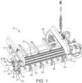
- FIG. 1 illustrates a portion of a drive end of a low-tension, direct drive conveyor belt system including a position limiter assembly 50 including roller limiters 60 forming spaces 70 therebetween for accommodating flights in a conveyor belt according to one embodiment of the invention.
- the illustrative drive end assembly 10 includes a pair of spaced apart, opposing end plates 12, 14 for mounting various components and forming a drive end of a conveyor.
- Each end plate includes an upper opening 22, shown as an open recess, for receiving a drive shaft 40, on which a full-width sprocket 42 or other conveyor drive is mounted.
- a motor 80 or other means drives the sprocket 42.
- the drive shaft is mounted in a bearing 46 at each end. Each bearing may be integrated into the opening 22, or may be attached to an end plate 12, 14 using fasteners 48, as shown.
- a lower opening 24 in each end plate mounts the position limiter assembly 50.
- the position limiter assembly ensures proper engagement between a conveyor belt and the drive for the conveyor belt.
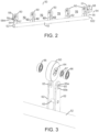
- the illustrative position limiter assembly 50 shown in FIG. 2 , has a mounting portion for mounting the comprises a mounting bar 52 extending from a first end 521 to a second end 522.
- a mounting portion mounts the mounting bar 52 between the end plates 12, 14 in a selected position.
- the illustrative mounting portion comprises assembly mounting arms 54 extending up from each end of the mounting bar for mounting the position limiter assembly 50 to the end plates 12, 14.
- the illustrative mounting arms 54 comprise a vertical neck portion 55 extending from the top of the mounting bar 52 and a head 56 at the end of the neck.
- the head 56 comprises a cylindrical base 57 connected to the neck 55 and a narrowed boss 58 having an opening 59 in an end face thereof.
- the illustrative opening 59 is offset from the central axis of the head. 56.
- the bosses 58 extend outward from the cylindrical bases 57 for insertion in the lower opening 24 of the end plates 12, 14.
- the illustrative boss 58 has a flat top wall, flat bottom wall, rounded rear wall 584 and rounded front wall (as described below).
- each lower opening 24 is configured to receive a head 56 of a position limiter assembly 50.
- the illustrative lower opening 24 comprises an open slot 25 extending to the front of the end plate and a receptacle 26 for receiving the boss 58.
- the illustrative receptacle 26 of FIG. 1 is cylindrical, but the receptacle can alternatively have flat sides or be otherwise shaped to accommodate the head 56 of a position limiter assembly.
- a central opening 27 receives a removable fastener 28 that extends into and is received in opening 59 in the head 56 to mate the position limiter assembly 50 with the end plate 12 and hold the position limiter assembly in an operating position.
- the invention is not limited to the illustrative assembly mounting arms 54 for mounting the position limiter assembly 50 to the end plates 12, 14.
- the end plates 12,14 include lower openings that receive the mounting bar 52 directly or another protrusion from the mounting bar without using the mounting arms 54 and head 56.
- the lower opening 24 would be lower than the embodiment of FIG. 1 .
- Any suitable means for mounting a position limiter assembly to a conveyor frame may be used.
- the position limiter assembly 50 further includes a plurality of roller limiters mounted along the length of the mounting bar 52 at select intervals.
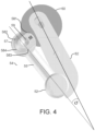
- the illustrative roller limiters comprise rollers 60 mounted to the mounting bar using roller mounting arms 62 that extend up from the front of the mounting bar.
- the rollers may be formed of plastic or another suitable material.
- the rollers 60 are mounted close to the sprocket 42 to ensure engagement between a drive tooth and a drive element on the sprocket, as shown in FIG. 1 .
- Each roller limiter comprises a pair of opposing mounting arms 62 welded or otherwise affixed to the front of the mounting bar 52, but the invention is not so limited.
- a support beam 63 can extend between each pair of roller mounting arms 62.
- the roller mounting arms 62 include keyhole-shaped openings 65 for mounting a roller axle 64.
- Each illustrative roller 60 includes a pair of bearings 66, a spacer 67 and the axle 64 press fit into the central opening of the roller portion 60, with the axle 64 protruding by slightly more than the thickness of a mounting arm 62 on each side.
- the keyhole-shaped opening 65 has a wider upper portion 65a for inserting the axle 64. In operation, the axle 64 rests in the smaller lower portion 65b, which prevents the roller 60 from escaping or moving out of position.
- the keyhole shape allows selective movement of the axle for cleaning.
- the opening 65 is not limited to the illustrative keyhole shape and may have any suitable size, shape and configuration that facilitates mounting of the rollers 60 while allowing selective movement of the rollers for cleaning or for another purpose.
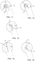
- the illustrative roller mounting arms 62 extend at an angle relative to the assembly mounting arms 54 at the ends of the mounting bar 52.
- the roller mounting arms 62 extend at an angle ⁇ between about 10° and about 30°, and preferably between about 15° and about 25°, relative to the assembly mounting arms 54 and neck 55 of the mounting arm 54 to properly position the rollers 60 in the drive end assembly 10.
- ⁇ between about 10° and about 30°, and preferably between about 15° and about 25°
- the front curved wall 581 of the boss 58 is coextensive with the cylindrical base 57, while the top flat wall 582, bottom flat wall 583 and rear curved wall 584 are smaller than or inset from the cylindrical base 57, forming a C-shaped shelf between the base 57 and boss 58.
- the rollers 60 are spaced along the mounting bar 52 to accommodate flights in an associated conveyor belt as the sprocket drives the conveyor belt.
- the illustrative position limiter assembly 50 includes a roller limiter assembly near each end 521 and 522, and three rollers spaced across the length of the mounting bar, designed to be placed in spaces between flights on the belt to contact or be placed close to the upper surface of the conveyor belt in those spaces.
- the flights can pass through the spaces 70 between the roller mounting arms and the mounting bar, while the roller 60 extend to the conveying surface to ensure proper engagement between the sprocket or other drive and the drive teeth of the conveyor belt.
- FIGS. 5-8 show another embodiment of a position limiter assembly including a double wheel design, though the invention is not so limited.
- each roller limiter 160 comprises a pair spaced-apart of rollers 161, 162 mounted on an axle 163 using bearings 164.
- the illustrative rollers are press fit onto the axle 163, though the invention is not so limited.
- a mounting arm 172 connects the rollers 161, 162 to a mounting bar 152.
- the illustrative mounting arm 172 includes a base portion 173, a threaded first end 174 for connecting the mounting arm 172 to the mounting bar 152 and a slotted second end 175 for mounting the roller limiter 160.
- the slotted second end 175 is thinner than the base 173 and extends between the rollers 161, 162 with the axle 163 extending through the slotted second end 175 to allow free rotation of the rollers 161, 162 during operation.
- the illustrative threaded first end 174 may be received in a corresponding opening 153 in the mounting bar 152, but other suitable means for mounting the rollers to the mounting bar of a position limiter assembly may be used.
- the slotted second end 175 of the mounting bar 172 is configured to allow assembly and disassembly of the roller limiter 160 only when a user properly aligns the axle 163 and provides a required force.
- the illustrative slotted second end 175 has a tapered down thickness to fit between the two rollers 161, 162, as shown in FIGS. 6 and 7 .
- the slotted second end 175 includes a first slot 176 and a second slot 177 that intersects the first slot at an angle and is open.
- the first slot 176 forms an operation slot for the axle and the second slot 177 forms an installation slot.
- FIG. 10 is an isometric view of the axle 163 on which the rollers 161 and 162 are mounted.
- the axle 163 includes a narrow central portion 167 having flat sides and roller mounting portions 168 that allow free rotation of the rollers 161, 162 about the axle 163.
- FIGS. 11-15 show the process of mounting the double roller 160 on the mounting bar 172 according to an embodiment of the invention.
- FIGS. 11-15 show the double roller 160 with one roller removed in order to demonstrate insertion of the axle 163 into the slots 176, 177.
- the double roller 160 is oriented so that the axle narrow central portion 167 between the rollers 161, 162 can enter the installation slot 177. In this orientation, a flat side of the axle narrow central portion 167 rests against or close to one or both walls of the installation slot 177. Then, the axle is pushed into the installation slot 177, as shown in FIG. 12 .
- the illustrative installation slot 177 is sized to provide an interference fit with the axle narrow central portion, so that a user must provide a certain amount of force to cause the axle to slide inwards towards the operation slot 176, as show in FIG. 13 .
- the axle 163 rotates and falls into an operating position in the operation slot 176, as shown in FIG. 14 .
- the illustrative configuration captures the axle 163 and prevents dismounting of the roller assembly 160 during operation, because the axle narrow central portion 167 cannot re-enter the installation slot 177 without proper alignment and significant removal force.
- the rollers 161 and 162 are fully supported and straddle the mounting arm 172, freely rotating about the axle 163.
- the slot 176 is sized such that the tip 179 of the second end of the mounting arm 172 does not reach the outer rim of the rollers 161, 162 during operation.
- the axle narrow central portion 167 has a clearance fit (i.e., the operating slot 176 is slightly wider than the axle narrow central portion 167, while the installation slot 177 may be smaller than or about the same width as the axle narrow central portion 167), allowing the axle to slide towards the tip 179 of the mounting arm within the slot 176 when the mounting arm 172 is inverted.
- the axle 163 remains in the operating position of FIG. 14 .
- FIG. 15 shows the axle narrow central portion 163 in a cleaning position within the slot 176.
- the axle 163 can slide through the operating slot 176 to allow access to the slot faces for cleaning, the axle 163 can easily slide back into the operating position shown in FIG. 14 , without easily entering into the installation slot 177.
- FIGS. 16 and 17 show a drive end of a low-tension, direct drive conveyor belt system 100 including a position limiter assembly 150 including the double roller design shown in FIGS. 5-15 .
- the illustrative position limiter assembly 150 includes a plurality of double roller position limiters 160 mounted to a mounting bar 152 using mounting arms 172.
- the double roller position limiters 160 are spaced apart to accommodate flights in a conveyor belt according to one embodiment of the invention.
- the illustrative drive end assembly 100 includes a pair of spaced apart, opposing end plates 112,114 for mounting various components and forming a drive end of a conveyor.
- Each end plate includes an upper opening 122 with an integrated bearing for receiving a drive shaft 140, on which a full-width sprocket1 142 or other conveyor drive is mounted.
- the position limiter assembly 150 includes assembly mounting arms 154 at the ends of the mounting bar 152 for placing the position limiters 160 in an operating position relative to the sprocket 142.
- the end plates 112, 114 include lower openings 124 for configured to receive a connecting portion of the mounting arms 154, as described above.
- the roller mounting arms 172 and assembly mounting arms 154 extend at an angle relative to each other, so that when the assembly mounting arms 154 hang vertically, the roller mounting arms 172 extend slightly forward at an angle between about 10° and about 30°, and preferably between about 15° and about 25°, to properly position the rollers 160 relative to the sprocket 142 or other drive means.
- a roller limiter 260 in another embodiment, shown in FIGS. 18-21 , includes a single roller 261 mounted on an axle 263 using bearings 264.
- the roller 261 is mounted to a roller mounting arm 272 to integrate the roller 261 with a position limiter assembly.
- the axle shown in FIG. 17 , includes a central roller-mounting portion 268 and two flat-sided protrusions 267.
- the illustrative mounting arm 272 includes a pair of spaced-apart fingers 280, 281 for rotatably receiving the roller 261 therebetween.
- Each finger 280, 281 include a first slot 276 and a second slot 277 that intersects the first slot at an angle and is open.
- the first slot 276 forms an operation slot for the axle and the second slot 277 forms an installation slot, similar to the operation slot 176 and installation slot 277 described above.
- the position limiter 260 can be mounted to the mounting arm 272 by orienting the axle protrusions 267 and pushing them through the second slot 277, then rotating the protrusions 267 and allowing them to fall into operating position in the first slot 276.
- Other suitable means for mounting a roller forming a position limiter to a mounting member may be used.
- a roller mounting arm 372 for mounting a roller to a position limiter assembly may include a relief slot 379, in addition to an operation slot 376 and an insertion slot 377 intersecting the operation slot at an angle.
- the relief slot allows the upper portion 375 to have more flexibility, facilitating larger interferences and increased tolerance on the slot width.
- the relief slot 379 may also protect against permanent deformation of the upper portion of the insertion slot 377.
- a roller mounting arm 472 for mounting a roller to a position limiter assembly may include an operation slot 476 that has a large chamfer 479 in an upper portion to facilitate cleaning of an axle of the roller when in a cleaning position.
- a mounting arm 572 for mounting a roller to a position limiter assembly may include an upper portion that tapers in thickness to facilitate cleaning of a roller axle 563 when a roller limiter 560 is in a cleaning position in an operation slot 576 of the mounting arm 572.
- the reduces thickness of the upper portion 575 around the upper portion of the operation slot 576 exposes the axle 563 when the axle travels into the upper portion to facilitate cleaning of the axle 563.
Landscapes
- Engineering & Computer Science (AREA)
- Mechanical Engineering (AREA)
- Rollers For Roller Conveyors For Transfer (AREA)
- Structure Of Belt Conveyors (AREA)
Description
- This application claims priority to
US Provisional Patent Application Number 62/646,478 filed March 22, 2018 - The present invention relates to power-driven conveyors. More particularly, the invention relates to infeed and outfeed assemblies for a conveyor to transition conveyed items onto and off of the conveyor and position limiters for ensuring proper engagement between a conveyor belt and a drive.
- Power-driven conveyors are used to convey items. Position limiters, such as described in
US Patent Number 7,850,562 are used in low tension, positive drive belting systems to ensure proper engagement of the belt and drive sprocket by controlling the position of the belt during the drive tooth hand-off process. A position limiter may be disposed against the belt near the exit point. Examples of position limiters include scrapers, rollers and shoes. - Current position limiters are fixed to a mounting shaft, which may trap dirt and debris and inhibit disassembly and-or replacement of the position limiter. In addition, current position limiters are generally placed where the conveyor belt would naturally fall away from the drive sprocket when no pretension is applied, which is typically at 165° of wrap from where the belt enters the drive sprocket. The position limiter thus competes for the same space as a belt scraper, if used. Further, the position limiter must be axially aligned with the drive sprockets, requiring locking collars or fasteners that can become harborage zones for bacteria, thus presenting risks to food safety. In addition, conveyor belts with flights make use of a position limiter difficult.
-
EP 3097 030 A1 discloses a conveyor employing a low-tension, direct drive conveyor belt, and a snap-on position limiter for ensuring proper engagement of the belt and a drive sprocket. The position limiter includes a body, a limiting surface and a snap clap opposite the limiting surface for snapping the position limiter to a mounting shaft. The limiting surface may comprise rotatable rollers mounted to the body, or a continuous arcuate surface. The position limiter may include a mounting arm for mounting a conveyor belt scraper at the front of the position limiter.EP 3097 030 A1 discloses a conveyor according to the preamble ofclaims 1, 12 and 13. - An end assembly for a conveyor comprises opposing end plates, a drive extending between the end plates and a position limiter assembly extending between the end plates below the drive for ensuring proper engagement of a conveyor belt with the drive. The position limiter comprises a series of spaced apart rollers mounted to and spaced from a mounting bar extending between the end plates. The appended
independent claims 1, 12 and 13 disclose aspects of the invention. The dependent claims further specify optional features of those aspects. -
-
FIG. 1 is an isometric view of a drive end of a low-tension, direct drive conveyor belt system including a position limiter assembly designed to accommodate flights in a conveyor belt; -
FIG. 2 is an isometric view of the position limiter assembly of the system ofFIG. 1 ; -
FIG. 3 is an exploded view of a roller in the position limiter assembly ofFIG. 2 ; -
FIG. 4 is an end view of the position limiter assembly ofFIG. 2 -
FIG. 5 is an isometric view of a roller limiter suitable for use in a position limiter assembly according to another embodiment of the invention; -
FIG. 6 is a front view of the roller limiter ofFIG. 5 ; -
FIG. 7 is a cross-sectional view of the roller limiter ofFIG. 5 ; -
FIG. 8 is an exploded view of the roller limiter ofFIG. 5 separated from the associated mounting arm; -
FIG. 9 is a side view of a mounting arm for a position limiter assembly according to an embodiment of the invention; -
FIG. 10 is an isometric view of an axle suitable for mounting a roller in a position limiter assembly according to an embodiment of the invention; -
FIG. 11 is a side view of a portion of a roller oriented for mounting to a mounting arm of a position limiter assembly according to an embodiment of the invention; -
FIG. 12 shows the roller portion ofFIG. 11 during initial insertion into the mounting arm; -
FIG. 13 shows the roller portion ofFIG. 11 during insertion into the mounting arm; -
FIG. 14 shows the roller portion ofFIG. 11 in an operating position; -
FIG. 15 shows the roller portion ofFIG. 11 in a cleaning position; -
FIG. 16 is an isometric view of a drive end of a low-tension, direct drive conveyor belt system including the roller limiter ofFIG. 5 in a position limiter assembly designed to accommodate flights in a conveyor belt according to an embodiment; -
FIG. 17 is a side view of the drive end ofFIG. 16 ; -
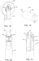
FIG. 18 is an isometric view of a roller and mounting arm for a position limiter assembly according to another embodiment of the invention; -
FIG. 19 is an isometric view of the axle of the roller ofFIG. 18 ; -
FIG. 20 is a cross-sectional view of the assembly ofFIG. 18 ; -
FIG. 21 is an isometric view of the end portion of the mounting arm ofFIG. 18 ; -
FIG. 22 is a side view of an end portion of a mounting arm for a position limiter assembly including a relief slot according to another embodiment of the invention; -
FIG. 23 is an isometric view of an end portion of a mounting arm for a position limiter assembly including cleaning chamfers, according to another embodiment of the invention; -
FIG. 24 is a front view of a roller and mounting arm for a position limiter assembly according to another embodiment of the invention; -
FIG. 25 shows the end portion of the mounting arm ofFIG. 24 . - A conveyor system includes a position limiter assembly for ensuring proper engagement between drive elements on a conveyor belt and a drive that can accommodate flights in the conveyor belt. The invention will be described below relative to certain illustrative embodiments, though the invention is not limited to the illustrative embodiments.
-
FIG. 1 illustrates a portion of a drive end of a low-tension, direct drive conveyor belt system including aposition limiter assembly 50 includingroller limiters 60 formingspaces 70 therebetween for accommodating flights in a conveyor belt according to one embodiment of the invention. The illustrativedrive end assembly 10 includes a pair of spaced apart, opposingend plates 12, 14 for mounting various components and forming a drive end of a conveyor. Each end plate includes anupper opening 22, shown as an open recess, for receiving adrive shaft 40, on which a full-width sprocket 42 or other conveyor drive is mounted. Amotor 80 or other means drives thesprocket 42. The drive shaft is mounted in abearing 46 at each end. Each bearing may be integrated into theopening 22, or may be attached to anend plate 12, 14 usingfasteners 48, as shown. - A
lower opening 24 in each end plate mounts theposition limiter assembly 50. The position limiter assembly ensures proper engagement between a conveyor belt and the drive for the conveyor belt. The illustrativeposition limiter assembly 50, shown inFIG. 2 , has a mounting portion for mounting the comprises amounting bar 52 extending from afirst end 521 to asecond end 522. A mounting portion mounts themounting bar 52 between theend plates 12, 14 in a selected position. The illustrative mounting portion comprisesassembly mounting arms 54 extending up from each end of the mounting bar for mounting theposition limiter assembly 50 to theend plates 12, 14. The illustrative mountingarms 54 comprise avertical neck portion 55 extending from the top of the mountingbar 52 and a head 56 at the end of the neck. The head 56 comprises acylindrical base 57 connected to theneck 55 and a narrowedboss 58 having anopening 59 in an end face thereof. Theillustrative opening 59 is offset from the central axis of the head. 56. Thebosses 58 extend outward from thecylindrical bases 57 for insertion in thelower opening 24 of theend plates 12, 14. Theillustrative boss 58 has a flat top wall, flat bottom wall, roundedrear wall 584 and rounded front wall (as described below). - Referring back to
FIG. 1 , eachlower opening 24 is configured to receive a head 56 of aposition limiter assembly 50. The illustrativelower opening 24 comprises anopen slot 25 extending to the front of the end plate and areceptacle 26 for receiving theboss 58. Theillustrative receptacle 26 ofFIG. 1 is cylindrical, but the receptacle can alternatively have flat sides or be otherwise shaped to accommodate the head 56 of a position limiter assembly. Acentral opening 27 receives aremovable fastener 28 that extends into and is received in opening 59 in the head 56 to mate theposition limiter assembly 50 with theend plate 12 and hold the position limiter assembly in an operating position. - The invention is not limited to the illustrative
assembly mounting arms 54 for mounting theposition limiter assembly 50 to theend plates 12, 14. In another embodiment of the invention, theend plates 12,14 include lower openings that receive the mountingbar 52 directly or another protrusion from the mounting bar without using the mountingarms 54 and head 56. In such an embodiment, thelower opening 24 would be lower than the embodiment ofFIG. 1 . Any suitable means for mounting a position limiter assembly to a conveyor frame may be used. - Referring to
FIGS. 2 and 3 , theposition limiter assembly 50 further includes a plurality of roller limiters mounted along the length of the mountingbar 52 at select intervals. The illustrative roller limiters compriserollers 60 mounted to the mounting bar usingroller mounting arms 62 that extend up from the front of the mounting bar. The rollers may be formed of plastic or another suitable material. When assembled, therollers 60 are mounted close to thesprocket 42 to ensure engagement between a drive tooth and a drive element on the sprocket, as shown inFIG. 1 . Each roller limiter comprises a pair of opposing mountingarms 62 welded or otherwise affixed to the front of the mountingbar 52, but the invention is not so limited. Asupport beam 63 can extend between each pair ofroller mounting arms 62. Theroller mounting arms 62 include keyhole-shapedopenings 65 for mounting aroller axle 64. Eachillustrative roller 60 includes a pair ofbearings 66, a spacer 67 and theaxle 64 press fit into the central opening of theroller portion 60, with theaxle 64 protruding by slightly more than the thickness of a mountingarm 62 on each side. The keyhole-shapedopening 65 has a widerupper portion 65a for inserting theaxle 64. In operation, theaxle 64 rests in the smallerlower portion 65b, which prevents theroller 60 from escaping or moving out of position. The keyhole shape allows selective movement of the axle for cleaning. Theopening 65 is not limited to the illustrative keyhole shape and may have any suitable size, shape and configuration that facilitates mounting of therollers 60 while allowing selective movement of the rollers for cleaning or for another purpose. - The illustrative
roller mounting arms 62 extend at an angle relative to theassembly mounting arms 54 at the ends of the mountingbar 52. For example, as shown inFIG. 4 , theroller mounting arms 62 extend at an angle θ between about 10° and about 30°, and preferably between about 15° and about 25°, relative to theassembly mounting arms 54 andneck 55 of the mountingarm 54 to properly position therollers 60 in thedrive end assembly 10. As shown also inFIG. 4 , in the illustrative embodiment, the frontcurved wall 581 of theboss 58 is coextensive with thecylindrical base 57, while the topflat wall 582, bottomflat wall 583 and rearcurved wall 584 are smaller than or inset from thecylindrical base 57, forming a C-shaped shelf between the base 57 andboss 58. - The
rollers 60 are spaced along the mountingbar 52 to accommodate flights in an associated conveyor belt as the sprocket drives the conveyor belt. For example, the illustrativeposition limiter assembly 50 includes a roller limiter assembly near eachend spaces 70 between the roller mounting arms and the mounting bar, while theroller 60 extend to the conveying surface to ensure proper engagement between the sprocket or other drive and the drive teeth of the conveyor belt. -
FIGS. 5-8 show another embodiment of a position limiter assembly including a double wheel design, though the invention is not so limited. In the embodiment ofFIGS. 5-8 , eachroller limiter 160 comprises a pair spaced-apart ofrollers axle 163 usingbearings 164. The illustrative rollers are press fit onto theaxle 163, though the invention is not so limited. A mountingarm 172 connects therollers bar 152. Theillustrative mounting arm 172 includes abase portion 173, a threadedfirst end 174 for connecting the mountingarm 172 to the mountingbar 152 and a slottedsecond end 175 for mounting theroller limiter 160. The slottedsecond end 175 is thinner than the base 173 and extends between therollers axle 163 extending through the slottedsecond end 175 to allow free rotation of therollers first end 174 may be received in acorresponding opening 153 in the mountingbar 152, but other suitable means for mounting the rollers to the mounting bar of a position limiter assembly may be used. - Referring to
FIG. 9 , the slottedsecond end 175 of the mountingbar 172 is configured to allow assembly and disassembly of theroller limiter 160 only when a user properly aligns theaxle 163 and provides a required force. The illustrative slottedsecond end 175 has a tapered down thickness to fit between the tworollers FIGS. 6 and 7 . The slottedsecond end 175 includes afirst slot 176 and asecond slot 177 that intersects the first slot at an angle and is open. Thefirst slot 176 forms an operation slot for the axle and thesecond slot 177 forms an installation slot. -
FIG. 10 is an isometric view of theaxle 163 on which therollers axle 163 includes a narrowcentral portion 167 having flat sides androller mounting portions 168 that allow free rotation of therollers axle 163. -
FIGS. 11-15 show the process of mounting thedouble roller 160 on the mountingbar 172 according to an embodiment of the invention.FIGS. 11-15 show thedouble roller 160 with one roller removed in order to demonstrate insertion of theaxle 163 into theslots FIG. 11 , thedouble roller 160 is oriented so that the axle narrowcentral portion 167 between therollers installation slot 177. In this orientation, a flat side of the axle narrowcentral portion 167 rests against or close to one or both walls of theinstallation slot 177. Then, the axle is pushed into theinstallation slot 177, as shown inFIG. 12 . Theillustrative installation slot 177 is sized to provide an interference fit with the axle narrow central portion, so that a user must provide a certain amount of force to cause the axle to slide inwards towards theoperation slot 176, as show inFIG. 13 . After clearing the interference zone formed byinstallation slot 177, theaxle 163 rotates and falls into an operating position in theoperation slot 176, as shown inFIG. 14 . The illustrative configuration captures theaxle 163 and prevents dismounting of theroller assembly 160 during operation, because the axle narrowcentral portion 167 cannot re-enter theinstallation slot 177 without proper alignment and significant removal force. In the operating position, therollers arm 172, freely rotating about theaxle 163. Theslot 176 is sized such that thetip 179 of the second end of the mountingarm 172 does not reach the outer rim of therollers central portion 167 has a clearance fit (i.e., theoperating slot 176 is slightly wider than the axle narrowcentral portion 167, while theinstallation slot 177 may be smaller than or about the same width as the axle narrow central portion 167), allowing the axle to slide towards thetip 179 of the mounting arm within theslot 176 when the mountingarm 172 is inverted. However, during operation, when the mountingarm 172 is located beneath a sprocket and conveyor belt to place therollers axle 163 remains in the operating position ofFIG. 14 . -
FIG. 15 shows the axle narrowcentral portion 163 in a cleaning position within theslot 176. Theaxle 163 can slide through theoperating slot 176 to allow access to the slot faces for cleaning, theaxle 163 can easily slide back into the operating position shown inFIG. 14 , without easily entering into theinstallation slot 177. -
FIGS. 16 and 17 show a drive end of a low-tension, direct drive conveyor belt system 100including aposition limiter assembly 150 including the double roller design shown inFIGS. 5-15 . The illustrativeposition limiter assembly 150 includes a plurality of doubleroller position limiters 160 mounted to a mountingbar 152 using mountingarms 172. The doubleroller position limiters 160 are spaced apart to accommodate flights in a conveyor belt according to one embodiment of the invention. The illustrativedrive end assembly 100 includes a pair of spaced apart, opposing end plates 112,114 for mounting various components and forming a drive end of a conveyor. Each end plate includes an upper opening 122 with an integrated bearing for receiving adrive shaft 140, on which a full-width sprocket1 142 or other conveyor drive is mounted. - The
position limiter assembly 150 includesassembly mounting arms 154 at the ends of the mountingbar 152 for placing theposition limiters 160 in an operating position relative to thesprocket 142. Theend plates lower openings 124 for configured to receive a connecting portion of the mountingarms 154, as described above. As shown inFIG. 17 , theroller mounting arms 172 andassembly mounting arms 154 extend at an angle relative to each other, so that when theassembly mounting arms 154 hang vertically, theroller mounting arms 172 extend slightly forward at an angle between about 10° and about 30°, and preferably between about 15° and about 25°, to properly position therollers 160 relative to thesprocket 142 or other drive means. - In another embodiment, shown in
FIGS. 18-21 , aroller limiter 260 includes asingle roller 261 mounted on anaxle 263 usingbearings 264. Theroller 261 is mounted to aroller mounting arm 272 to integrate theroller 261 with a position limiter assembly. The axle, shown inFIG. 17 , includes a central roller-mountingportion 268 and two flat-sided protrusions 267. Theillustrative mounting arm 272 includes a pair of spaced-apart fingers roller 261 therebetween. Eachfinger first slot 276 and asecond slot 277 that intersects the first slot at an angle and is open. Thefirst slot 276 forms an operation slot for the axle and thesecond slot 277 forms an installation slot, similar to theoperation slot 176 andinstallation slot 277 described above. Theposition limiter 260 can be mounted to the mountingarm 272 by orienting theaxle protrusions 267 and pushing them through thesecond slot 277, then rotating theprotrusions 267 and allowing them to fall into operating position in thefirst slot 276. Other suitable means for mounting a roller forming a position limiter to a mounting member may be used. - In one embodiment, shown in
FIG. 22 , aroller mounting arm 372 for mounting a roller to a position limiter assembly may include arelief slot 379, in addition to anoperation slot 376 and aninsertion slot 377 intersecting the operation slot at an angle. The relief slot allows theupper portion 375 to have more flexibility, facilitating larger interferences and increased tolerance on the slot width. Therelief slot 379 may also protect against permanent deformation of the upper portion of theinsertion slot 377. - In another embodiment, shown in
FIG. 23 , aroller mounting arm 472 for mounting a roller to a position limiter assembly may include anoperation slot 476 that has alarge chamfer 479 in an upper portion to facilitate cleaning of an axle of the roller when in a cleaning position. - Other modifications to facilitate hygiene may also be used. For example, as shown in
FIGS. 24 and 25 , a mountingarm 572 for mounting a roller to a position limiter assembly may include an upper portion that tapers in thickness to facilitate cleaning of aroller axle 563 when aroller limiter 560 is in a cleaning position in anoperation slot 576 of the mountingarm 572. The reduces thickness of theupper portion 575 around the upper portion of theoperation slot 576 exposes theaxle 563 when the axle travels into the upper portion to facilitate cleaning of theaxle 563. - The scope of the claims is not meant to be limited to the details of the described exemplary embodiments.
Claims (15)
- A conveyor, comprising:a frame including opposing end plates (112, 114) at an end of the conveyor, each end plate (112, 114) including an upper opening (122) for mounting a drive shaft (140) and a lower opening (24) comprising a receptacle (26) for mounting a position limiter assembly (50); anda position limiter assembly (50) mounted in the frame, the position limiter assembly (50) comprising a mounting bar (152) extending from a first end (521) to a second end (522), a plurality of rollers mounted to a plurality of roller mounting arms (172; 372; 472; 572) extending from the mounting bar (152), and a mounting portion for mounting the mounting bar (152) between the end plates (112, 114);the conveyor being characterized in that each roller mounting arm (172; 372; 472; 572) includes a slotted end (175) for mounting an axle (163) on which an associated roller is mounted;and in that the slotted end (175) includes an operation slot (176; 376; 476; 576) and an open installation slot (177; 377) intersecting the operation slot (176; 376; 476; 576) at an angle; andand in that the roller comprises a pair of spaced-apart rollers (161, 162) rotatably mounted on an axle (163; 563), the axle (163; 563) including roller mounting portions (168) and a narrow central portion (167) having flat sides configured to be received in the slotted end (175) of the associated roller mounting arms (172; 372).
- The conveyor of claim 1, wherein the mounting portion comprises:a first assembly mounting arm (54) extending from the first end (521) of the mounting bar (152); anda second assembly mounting arm (54) extending from the second end (522) of the mounting bar (152), each mounting bar (152) including a boss (58) that is received in a receptacle (26) of an end plate.
- The conveyor of claim 1, wherein the roller mounting arms (172) extend at an angle of between about 10° and about 30° relative to the assembly mounting arms (154).
- The conveyor of claim 1, wherein the roller mounting arms include a keyhole-shaped opening (65) for receiving an axle of the roller.
- The conveyor of claim 1, wherein the operation slot (176) is wider than the installation slot (177).
- The conveyor of claim 1, wherein the slotted end further includes a relief slot (379) intersecting the operation slot (376).
- The conveyor of claim 1, wherein the operation slot (476) has a large chamfer (479) in an upper portion to facilitate hygiene.
- The conveyor of claim 1, wherein each roller mounting arm (572) includes an upper portion that tapers in thickness around an upper portion of the operation slot (576).
- The conveyor of claim 2, wherein each assembly mounting arm comprises a neck (55) extending from the mounting bar (52), a cylindrical base (57) at the end of the neck (55) and an outward-extending boss (58) extending from the cylindrical base (57).
- The conveyor of claim 9, wherein the outward-extending boss (58) includes an opening (59) for receiving a fastener (28) inserted through an opening in the receptacle of the end plate.
- The conveyor of claim 10, wherein a) the opening (59) for the fastener is offset from a central axis of the cylindrical base (57); or b) the opening (59) for the fastener is offset from a central axis of the cylindrical base (57) and wherein the outward-extending boss (58) and cylindrical base (57) form a C-shaped shelf at an intersection therebetween.
- A conveyor, comprising:a frame including opposing end plates (112, 114) at an end of the conveyor, each end plate (112, 114) including an upper opening (122) for mounting a drive shaft (140) and a lower opening (24) comprising a receptacle (26) for mounting a position limiter assembly (50); anda position limiter assembly (50) mounted in the frame, the position limiter assembly (50) comprising a mounting bar (152) extending from a first end (521) to a second end (522), a plurality of rollers mounted to a plurality of roller mounting arms (572) extending from the mounting bar (152), and a mounting portion for mounting the mounting bar (152) between the end plates (112, 114);the conveyor being characterized in that each roller mounting arm (572) includes a slotted end (175) for mounting an axle (163) on which an associated roller is mounted;and in that the slotted end (175) includes an operation slot (576) and an open installation slot (177; 377) intersecting the operation slot (576) at an angle; andand in that each roller mounting arm (572) includes an upper portion that tapers in thickness around an upper portion of the operation slot (576).
- A conveyor, comprising:a frame including opposing end plates (112, 114) at an end of the conveyor, each end plate (112, 114) including an upper opening (122) for mounting a drive shaft (140) and a lower opening (24) comprising a receptacle (26) for mounting a position limiter assembly (50); anda position limiter assembly (50) mounted in the frame, the position limiter assembly (50) comprising a mounting bar (152) extending from a first end (521) to a second end (522), a plurality of rollers mounted to a plurality of roller mounting arms (172; 372; 472; 572) extending from the mounting bar (152), and a mounting portion for mounting the mounting bar (152) between the end plates (112, 114);the conveyor being characterized in that the mounting portion comprises:a first assembly mounting arm (54) extending from the first end (521) of the mounting bar (152); and
a second assembly mounting arm (54) extending from the second end (522) of the mounting bar (152), each mounting bar (152) including a boss (58) that is received in a receptacle (26) of an end plate;and in that each assembly mounting arm comprises a neck (55) extending from the mounting bar (52), a cylindrical base (57) at the end of the neck (55) and an outward-extending boss (58) extending from the cylindrical base (57). - The conveyor of claim 13,
wherein the outward-extending boss (58) includes an opening (59) for receiving a fastener (28) inserted through an opening in the receptacle of the end plate. - The conveyor of claim 14,
wherein a) the opening (59) for the fastener is offset from a central axis of the cylindrical base (57); or b) the opening (59) for the fastener is offset from a central axis of the cylindrical base (57) and wherein the outward-extending boss (58) and cylindrical base (57) form a C-shaped shelf at an intersection therebetween.
Applications Claiming Priority (2)
| Application Number | Priority Date | Filing Date | Title |
|---|---|---|---|
| US201862646478P | 2018-03-22 | 2018-03-22 | |
| PCT/US2019/023345 WO2019183337A1 (en) | 2018-03-22 | 2019-03-21 | Position limiter for flighted conveyor belt |
Publications (3)
| Publication Number | Publication Date |
|---|---|
| EP3768617A1 EP3768617A1 (en) | 2021-01-27 |
| EP3768617A4 EP3768617A4 (en) | 2021-12-15 |
| EP3768617B1 true EP3768617B1 (en) | 2024-07-24 |
Family
ID=67987590
Family Applications (1)
| Application Number | Title | Priority Date | Filing Date |
|---|---|---|---|
| EP19771821.6A Active EP3768617B1 (en) | 2018-03-22 | 2019-03-21 | Position limiter for flighted conveyor belt |
Country Status (6)
| Country | Link |
|---|---|
| US (2) | US11214446B2 (en) |
| EP (1) | EP3768617B1 (en) |
| JP (1) | JP7354128B2 (en) |
| CN (1) | CN111712450A (en) |
| ES (1) | ES2989202T3 (en) |
| WO (1) | WO2019183337A1 (en) |
Families Citing this family (1)
| Publication number | Priority date | Publication date | Assignee | Title |
|---|---|---|---|---|
| EP3768617B1 (en) * | 2018-03-22 | 2024-07-24 | Laitram, LLC | Position limiter for flighted conveyor belt |
Family Cites Families (24)
| Publication number | Priority date | Publication date | Assignee | Title |
|---|---|---|---|---|
| JPS473931Y1 (en) * | 1969-10-03 | 1972-02-10 | ||
| JPS5320789U (en) * | 1976-07-30 | 1978-02-22 | ||
| DE9400258U1 (en) * | 1994-01-12 | 1995-05-18 | Schwarze, Hans-Otto, 45665 Recklinghausen | Device for stripping dirt from belt straps in the area of a drive or deflection roller |
| EP1345825A1 (en) * | 2000-11-29 | 2003-09-24 | Air Control Science, Inc. | Roller bed for a conveyor belt system |
| PL1838600T3 (en) | 2005-01-19 | 2012-01-31 | Thermodrive Llc | Low friction, direct drive conveyor belt |
| JP2005330100A (en) * | 2005-02-21 | 2005-12-02 | Porinesu:Kk | Wheel conveyor device |
| US20070175737A1 (en) * | 2006-01-31 | 2007-08-02 | Mol Belting Company | Conveyor with troughed low friction, positive drive belt |
| KR100822414B1 (en) * | 2006-11-08 | 2008-04-16 | 주식회사 포스코 | Roller support for belt conveyor |
| DE502007003745D1 (en) * | 2007-07-24 | 2010-06-24 | Innova Patent Gmbh | Storage unit for a conveyor system for transporting goods by means of a conveyor belt |
| KR20090111924A (en) * | 2008-04-23 | 2009-10-28 | 주식회사 케이에스피 | Return roller changer |
| EP3165245B1 (en) * | 2011-08-02 | 2019-02-20 | Medtronic, Inc. | Hemodialysis system having a flow path with a controlled compliant volume |
| US8936147B2 (en) * | 2012-04-06 | 2015-01-20 | Dorner Mfg. Corp. | Pinch roller drive |
| US9212004B2 (en) * | 2012-11-29 | 2015-12-15 | Canon Kabushiki Kaisha | Belt transporting device and image forming apparatus |
| CN203497571U (en) * | 2013-08-09 | 2014-03-26 | 陈水金 | Improved structure of the conveyor |
| US10077156B2 (en) * | 2014-01-24 | 2018-09-18 | Laitram, L.L.C. | Snap-on position limiter for a conveyor belt |
| WO2015112674A1 (en) * | 2014-01-24 | 2015-07-30 | Laitram, L.L.C. | Snap-on position limiter for a conveyor belt |
| ES2910704T3 (en) * | 2015-04-23 | 2022-05-13 | Laitram Llc | Input and output assemblies for a conveyor |
| ES3027192T3 (en) * | 2015-06-29 | 2025-06-13 | Laitram Llc | Self-biasing scraper for a conveyor belt |
| CN109153504B (en) * | 2016-05-24 | 2020-12-08 | 莱特拉姆有限责任公司 | Stopper Assembly for Conveyor Belts |
| WO2018057688A1 (en) | 2016-09-21 | 2018-03-29 | Laitram, L.L.C. | Infeed and outfeed assemblies for a conveyor |
| JP3210894U (en) * | 2016-12-27 | 2017-06-15 | 株式会社Jrc | Belt conveyor |
| US10280010B2 (en) * | 2017-08-24 | 2019-05-07 | Precision, Inc. | Scraper assemblies for removing carryover material from a conveyor belt or roller |
| EP3768617B1 (en) * | 2018-03-22 | 2024-07-24 | Laitram, LLC | Position limiter for flighted conveyor belt |
| BR112021023149A2 (en) * | 2019-05-20 | 2022-01-04 | Laitram Llc | Drive set for a conveyor belt and scraper set for a conveyor belt |
-
2019
- 2019-03-21 EP EP19771821.6A patent/EP3768617B1/en active Active
- 2019-03-21 WO PCT/US2019/023345 patent/WO2019183337A1/en not_active Ceased
- 2019-03-21 CN CN201980013015.2A patent/CN111712450A/en active Pending
- 2019-03-21 ES ES19771821T patent/ES2989202T3/en active Active
- 2019-03-21 JP JP2020545274A patent/JP7354128B2/en active Active
- 2019-03-21 US US16/977,930 patent/US11214446B2/en active Active
-
2021
- 2021-12-28 US US17/563,464 patent/US11787639B2/en active Active
Also Published As
| Publication number | Publication date |
|---|---|
| EP3768617A4 (en) | 2021-12-15 |
| US20200407170A1 (en) | 2020-12-31 |
| JP7354128B2 (en) | 2023-10-02 |
| ES2989202T3 (en) | 2024-11-25 |
| US11787639B2 (en) | 2023-10-17 |
| EP3768617A1 (en) | 2021-01-27 |
| US11214446B2 (en) | 2022-01-04 |
| WO2019183337A1 (en) | 2019-09-26 |
| US20220119200A1 (en) | 2022-04-21 |
| JP2021516650A (en) | 2021-07-08 |
| CN111712450A (en) | 2020-09-25 |
Similar Documents
| Publication | Publication Date | Title |
|---|---|---|
| US9914591B2 (en) | Cleanable conveyor frame assembly including snap-on components | |
| EP3097030B1 (en) | Snap-on position limiter for a conveyor belt | |
| US10427880B2 (en) | Snap-on position limiter for a conveyor belt | |
| US10035656B2 (en) | Infeed and outfeed assemblies for a conveyor | |
| EP3972918B1 (en) | Drive assembly for a conveyor | |
| JP6941174B2 (en) | Snap-type movement limiter for conveyor belts | |
| US11787639B2 (en) | Position limiter for flighted conveyor belt |
Legal Events
| Date | Code | Title | Description |
|---|---|---|---|
| STAA | Information on the status of an ep patent application or granted ep patent |
Free format text: STATUS: THE INTERNATIONAL PUBLICATION HAS BEEN MADE |
|
| PUAI | Public reference made under article 153(3) epc to a published international application that has entered the european phase |
Free format text: ORIGINAL CODE: 0009012 |
|
| STAA | Information on the status of an ep patent application or granted ep patent |
Free format text: STATUS: REQUEST FOR EXAMINATION WAS MADE |
|
| 17P | Request for examination filed |
Effective date: 20200810 |
|
| AK | Designated contracting states |
Kind code of ref document: A1 Designated state(s): AL AT BE BG CH CY CZ DE DK EE ES FI FR GB GR HR HU IE IS IT LI LT LU LV MC MK MT NL NO PL PT RO RS SE SI SK SM TR |
|
| AX | Request for extension of the european patent |
Extension state: BA ME |
|
| DAV | Request for validation of the european patent (deleted) | ||
| DAX | Request for extension of the european patent (deleted) | ||
| A4 | Supplementary search report drawn up and despatched |
Effective date: 20211115 |
|
| RIC1 | Information provided on ipc code assigned before grant |
Ipc: B65G 21/06 20060101ALI20211110BHEP Ipc: B65G 23/12 20060101ALI20211110BHEP Ipc: B65G 39/12 20060101ALI20211110BHEP Ipc: B65G 15/60 20060101AFI20211110BHEP |
|
| REG | Reference to a national code |
Ref country code: DE Ref legal event code: R079 Free format text: PREVIOUS MAIN CLASS: B65G0015600000 Ipc: B65G0021100000 Ref country code: DE Ref legal event code: R079 Ref document number: 602019055757 Country of ref document: DE Free format text: PREVIOUS MAIN CLASS: B65G0015600000 Ipc: B65G0021100000 |
|
| GRAP | Despatch of communication of intention to grant a patent |
Free format text: ORIGINAL CODE: EPIDOSNIGR1 |
|
| STAA | Information on the status of an ep patent application or granted ep patent |
Free format text: STATUS: GRANT OF PATENT IS INTENDED |
|
| RIC1 | Information provided on ipc code assigned before grant |
Ipc: B65G 21/06 20060101ALI20240125BHEP Ipc: B65G 39/12 20060101ALI20240125BHEP Ipc: B65G 15/60 20060101ALI20240125BHEP Ipc: B65G 23/12 20060101ALI20240125BHEP Ipc: B65G 23/22 20060101ALI20240125BHEP Ipc: B65G 21/10 20060101AFI20240125BHEP |
|
| INTG | Intention to grant announced |
Effective date: 20240216 |
|
| P01 | Opt-out of the competence of the unified patent court (upc) registered |
Effective date: 20240507 |
|
| GRAS | Grant fee paid |
Free format text: ORIGINAL CODE: EPIDOSNIGR3 |
|
| GRAA | (expected) grant |
Free format text: ORIGINAL CODE: 0009210 |
|
| STAA | Information on the status of an ep patent application or granted ep patent |
Free format text: STATUS: THE PATENT HAS BEEN GRANTED |
|
| AK | Designated contracting states |
Kind code of ref document: B1 Designated state(s): AL AT BE BG CH CY CZ DE DK EE ES FI FR GB GR HR HU IE IS IT LI LT LU LV MC MK MT NL NO PL PT RO RS SE SI SK SM TR |
|
| REG | Reference to a national code |
Ref country code: GB Ref legal event code: FG4D |
|
| REG | Reference to a national code |
Ref country code: CH Ref legal event code: EP |
|
| REG | Reference to a national code |
Ref country code: IE Ref legal event code: FG4D Ref country code: DE Ref legal event code: R096 Ref document number: 602019055757 Country of ref document: DE |
|
| REG | Reference to a national code |
Ref country code: NL Ref legal event code: FP |
|
| REG | Reference to a national code |
Ref country code: LT Ref legal event code: MG9D |
|
| REG | Reference to a national code |
Ref country code: ES Ref legal event code: FG2A Ref document number: 2989202 Country of ref document: ES Kind code of ref document: T3 Effective date: 20241125 |
|
| PG25 | Lapsed in a contracting state [announced via postgrant information from national office to epo] |
Ref country code: PT Free format text: LAPSE BECAUSE OF FAILURE TO SUBMIT A TRANSLATION OF THE DESCRIPTION OR TO PAY THE FEE WITHIN THE PRESCRIBED TIME-LIMIT Effective date: 20241125 |
|
| REG | Reference to a national code |
Ref country code: AT Ref legal event code: MK05 Ref document number: 1706134 Country of ref document: AT Kind code of ref document: T Effective date: 20240724 |
|
| PG25 | Lapsed in a contracting state [announced via postgrant information from national office to epo] |
Ref country code: PT Free format text: LAPSE BECAUSE OF FAILURE TO SUBMIT A TRANSLATION OF THE DESCRIPTION OR TO PAY THE FEE WITHIN THE PRESCRIBED TIME-LIMIT Effective date: 20241125 |
|
| PG25 | Lapsed in a contracting state [announced via postgrant information from national office to epo] |
Ref country code: NO Free format text: LAPSE BECAUSE OF FAILURE TO SUBMIT A TRANSLATION OF THE DESCRIPTION OR TO PAY THE FEE WITHIN THE PRESCRIBED TIME-LIMIT Effective date: 20241024 |
|
| PG25 | Lapsed in a contracting state [announced via postgrant information from national office to epo] |
Ref country code: GR Free format text: LAPSE BECAUSE OF FAILURE TO SUBMIT A TRANSLATION OF THE DESCRIPTION OR TO PAY THE FEE WITHIN THE PRESCRIBED TIME-LIMIT Effective date: 20241025 Ref country code: PL Free format text: LAPSE BECAUSE OF FAILURE TO SUBMIT A TRANSLATION OF THE DESCRIPTION OR TO PAY THE FEE WITHIN THE PRESCRIBED TIME-LIMIT Effective date: 20240724 Ref country code: FI Free format text: LAPSE BECAUSE OF FAILURE TO SUBMIT A TRANSLATION OF THE DESCRIPTION OR TO PAY THE FEE WITHIN THE PRESCRIBED TIME-LIMIT Effective date: 20240724 |
|
| PG25 | Lapsed in a contracting state [announced via postgrant information from national office to epo] |
Ref country code: BG Free format text: LAPSE BECAUSE OF FAILURE TO SUBMIT A TRANSLATION OF THE DESCRIPTION OR TO PAY THE FEE WITHIN THE PRESCRIBED TIME-LIMIT Effective date: 20240724 |
|
| PG25 | Lapsed in a contracting state [announced via postgrant information from national office to epo] |
Ref country code: LV Free format text: LAPSE BECAUSE OF FAILURE TO SUBMIT A TRANSLATION OF THE DESCRIPTION OR TO PAY THE FEE WITHIN THE PRESCRIBED TIME-LIMIT Effective date: 20240724 |
|
| PG25 | Lapsed in a contracting state [announced via postgrant information from national office to epo] |
Ref country code: IS Free format text: LAPSE BECAUSE OF FAILURE TO SUBMIT A TRANSLATION OF THE DESCRIPTION OR TO PAY THE FEE WITHIN THE PRESCRIBED TIME-LIMIT Effective date: 20241124 Ref country code: AT Free format text: LAPSE BECAUSE OF FAILURE TO SUBMIT A TRANSLATION OF THE DESCRIPTION OR TO PAY THE FEE WITHIN THE PRESCRIBED TIME-LIMIT Effective date: 20240724 |
|
| PG25 | Lapsed in a contracting state [announced via postgrant information from national office to epo] |
Ref country code: HR Free format text: LAPSE BECAUSE OF FAILURE TO SUBMIT A TRANSLATION OF THE DESCRIPTION OR TO PAY THE FEE WITHIN THE PRESCRIBED TIME-LIMIT Effective date: 20240724 |
|
| PG25 | Lapsed in a contracting state [announced via postgrant information from national office to epo] |
Ref country code: RS Free format text: LAPSE BECAUSE OF FAILURE TO SUBMIT A TRANSLATION OF THE DESCRIPTION OR TO PAY THE FEE WITHIN THE PRESCRIBED TIME-LIMIT Effective date: 20241024 |
|
| PG25 | Lapsed in a contracting state [announced via postgrant information from national office to epo] |
Ref country code: RS Free format text: LAPSE BECAUSE OF FAILURE TO SUBMIT A TRANSLATION OF THE DESCRIPTION OR TO PAY THE FEE WITHIN THE PRESCRIBED TIME-LIMIT Effective date: 20241024 Ref country code: PL Free format text: LAPSE BECAUSE OF FAILURE TO SUBMIT A TRANSLATION OF THE DESCRIPTION OR TO PAY THE FEE WITHIN THE PRESCRIBED TIME-LIMIT Effective date: 20240724 Ref country code: NO Free format text: LAPSE BECAUSE OF FAILURE TO SUBMIT A TRANSLATION OF THE DESCRIPTION OR TO PAY THE FEE WITHIN THE PRESCRIBED TIME-LIMIT Effective date: 20241024 Ref country code: LV Free format text: LAPSE BECAUSE OF FAILURE TO SUBMIT A TRANSLATION OF THE DESCRIPTION OR TO PAY THE FEE WITHIN THE PRESCRIBED TIME-LIMIT Effective date: 20240724 Ref country code: IS Free format text: LAPSE BECAUSE OF FAILURE TO SUBMIT A TRANSLATION OF THE DESCRIPTION OR TO PAY THE FEE WITHIN THE PRESCRIBED TIME-LIMIT Effective date: 20241124 Ref country code: HR Free format text: LAPSE BECAUSE OF FAILURE TO SUBMIT A TRANSLATION OF THE DESCRIPTION OR TO PAY THE FEE WITHIN THE PRESCRIBED TIME-LIMIT Effective date: 20240724 Ref country code: GR Free format text: LAPSE BECAUSE OF FAILURE TO SUBMIT A TRANSLATION OF THE DESCRIPTION OR TO PAY THE FEE WITHIN THE PRESCRIBED TIME-LIMIT Effective date: 20241025 Ref country code: FI Free format text: LAPSE BECAUSE OF FAILURE TO SUBMIT A TRANSLATION OF THE DESCRIPTION OR TO PAY THE FEE WITHIN THE PRESCRIBED TIME-LIMIT Effective date: 20240724 Ref country code: BG Free format text: LAPSE BECAUSE OF FAILURE TO SUBMIT A TRANSLATION OF THE DESCRIPTION OR TO PAY THE FEE WITHIN THE PRESCRIBED TIME-LIMIT Effective date: 20240724 Ref country code: AT Free format text: LAPSE BECAUSE OF FAILURE TO SUBMIT A TRANSLATION OF THE DESCRIPTION OR TO PAY THE FEE WITHIN THE PRESCRIBED TIME-LIMIT Effective date: 20240724 |
|
| PG25 | Lapsed in a contracting state [announced via postgrant information from national office to epo] |
Ref country code: DK Free format text: LAPSE BECAUSE OF FAILURE TO SUBMIT A TRANSLATION OF THE DESCRIPTION OR TO PAY THE FEE WITHIN THE PRESCRIBED TIME-LIMIT Effective date: 20240724 Ref country code: SM Free format text: LAPSE BECAUSE OF FAILURE TO SUBMIT A TRANSLATION OF THE DESCRIPTION OR TO PAY THE FEE WITHIN THE PRESCRIBED TIME-LIMIT Effective date: 20240724 Ref country code: RO Free format text: LAPSE BECAUSE OF FAILURE TO SUBMIT A TRANSLATION OF THE DESCRIPTION OR TO PAY THE FEE WITHIN THE PRESCRIBED TIME-LIMIT Effective date: 20240724 |
|
| PG25 | Lapsed in a contracting state [announced via postgrant information from national office to epo] |
Ref country code: EE Free format text: LAPSE BECAUSE OF FAILURE TO SUBMIT A TRANSLATION OF THE DESCRIPTION OR TO PAY THE FEE WITHIN THE PRESCRIBED TIME-LIMIT Effective date: 20240724 |
|
| PG25 | Lapsed in a contracting state [announced via postgrant information from national office to epo] |
Ref country code: CZ Free format text: LAPSE BECAUSE OF FAILURE TO SUBMIT A TRANSLATION OF THE DESCRIPTION OR TO PAY THE FEE WITHIN THE PRESCRIBED TIME-LIMIT Effective date: 20240724 |
|
| REG | Reference to a national code |
Ref country code: DE Ref legal event code: R097 Ref document number: 602019055757 Country of ref document: DE |
|
| PG25 | Lapsed in a contracting state [announced via postgrant information from national office to epo] |
Ref country code: SK Free format text: LAPSE BECAUSE OF FAILURE TO SUBMIT A TRANSLATION OF THE DESCRIPTION OR TO PAY THE FEE WITHIN THE PRESCRIBED TIME-LIMIT Effective date: 20240724 |
|
| PLBE | No opposition filed within time limit |
Free format text: ORIGINAL CODE: 0009261 |
|
| STAA | Information on the status of an ep patent application or granted ep patent |
Free format text: STATUS: NO OPPOSITION FILED WITHIN TIME LIMIT |
|
| 26N | No opposition filed |
Effective date: 20250425 |
|
| PGFP | Annual fee paid to national office [announced via postgrant information from national office to epo] |
Ref country code: ES Payment date: 20250409 Year of fee payment: 7 |
|
| PG25 | Lapsed in a contracting state [announced via postgrant information from national office to epo] |
Ref country code: SE Free format text: LAPSE BECAUSE OF FAILURE TO SUBMIT A TRANSLATION OF THE DESCRIPTION OR TO PAY THE FEE WITHIN THE PRESCRIBED TIME-LIMIT Effective date: 20240724 |
|
| PG25 | Lapsed in a contracting state [announced via postgrant information from national office to epo] |
Ref country code: MC Free format text: LAPSE BECAUSE OF FAILURE TO SUBMIT A TRANSLATION OF THE DESCRIPTION OR TO PAY THE FEE WITHIN THE PRESCRIBED TIME-LIMIT Effective date: 20240724 |
|
| REG | Reference to a national code |
Ref country code: CH Ref legal event code: H13 Free format text: ST27 STATUS EVENT CODE: U-0-0-H10-H13 (AS PROVIDED BY THE NATIONAL OFFICE) Effective date: 20251023 |
|
| PG25 | Lapsed in a contracting state [announced via postgrant information from national office to epo] |
Ref country code: LU Free format text: LAPSE BECAUSE OF NON-PAYMENT OF DUE FEES Effective date: 20250321 |
|
| REG | Reference to a national code |
Ref country code: BE Ref legal event code: MM Effective date: 20250331 |
|
| PG25 | Lapsed in a contracting state [announced via postgrant information from national office to epo] |
Ref country code: BE Free format text: LAPSE BECAUSE OF NON-PAYMENT OF DUE FEES Effective date: 20250331 |
|
| PG25 | Lapsed in a contracting state [announced via postgrant information from national office to epo] |
Ref country code: CH Free format text: LAPSE BECAUSE OF NON-PAYMENT OF DUE FEES Effective date: 20250331 |
|
| PG25 | Lapsed in a contracting state [announced via postgrant information from national office to epo] |
Ref country code: IE Free format text: LAPSE BECAUSE OF NON-PAYMENT OF DUE FEES Effective date: 20250321 |
|
| PGFP | Annual fee paid to national office [announced via postgrant information from national office to epo] |
Ref country code: NL Payment date: 20260211 Year of fee payment: 8 |
|
| PGFP | Annual fee paid to national office [announced via postgrant information from national office to epo] |
Ref country code: GB Payment date: 20260211 Year of fee payment: 8 |
|
| PGFP | Annual fee paid to national office [announced via postgrant information from national office to epo] |
Ref country code: DE Payment date: 20260213 Year of fee payment: 8 |
|
| PGFP | Annual fee paid to national office [announced via postgrant information from national office to epo] |
Ref country code: IT Payment date: 20260311 Year of fee payment: 8 |
|
| PGFP | Annual fee paid to national office [announced via postgrant information from national office to epo] |
Ref country code: FR Payment date: 20260209 Year of fee payment: 8 |
|
| PGFP | Annual fee paid to national office [announced via postgrant information from national office to epo] |
Ref country code: TR Payment date: 20260220 Year of fee payment: 8 |