EP3768368B1 - Implantable medical electrode assemblies - Google Patents
Implantable medical electrode assemblies Download PDFInfo
- Publication number
- EP3768368B1 EP3768368B1 EP19715645.8A EP19715645A EP3768368B1 EP 3768368 B1 EP3768368 B1 EP 3768368B1 EP 19715645 A EP19715645 A EP 19715645A EP 3768368 B1 EP3768368 B1 EP 3768368B1
- Authority
- EP
- European Patent Office
- Prior art keywords
- sleeve
- assembly
- distal
- electrode
- channels
- Prior art date
- Legal status (The legal status is an assumption and is not a legal conclusion. Google has not performed a legal analysis and makes no representation as to the accuracy of the status listed.)
- Active
Links
Images





Classifications
-
- A—HUMAN NECESSITIES
- A61—MEDICAL OR VETERINARY SCIENCE; HYGIENE
- A61N—ELECTROTHERAPY; MAGNETOTHERAPY; RADIATION THERAPY; ULTRASOUND THERAPY
- A61N1/00—Electrotherapy; Circuits therefor
- A61N1/02—Details
- A61N1/04—Electrodes
- A61N1/05—Electrodes for implantation or insertion into the body, e.g. heart electrode
- A61N1/056—Transvascular endocardial electrode systems
-
- A—HUMAN NECESSITIES
- A61—MEDICAL OR VETERINARY SCIENCE; HYGIENE
- A61N—ELECTROTHERAPY; MAGNETOTHERAPY; RADIATION THERAPY; ULTRASOUND THERAPY
- A61N1/00—Electrotherapy; Circuits therefor
- A61N1/02—Details
- A61N1/04—Electrodes
- A61N1/05—Electrodes for implantation or insertion into the body, e.g. heart electrode
- A61N1/056—Transvascular endocardial electrode systems
- A61N1/057—Anchoring means; Means for fixing the head inside the heart
- A61N1/0573—Anchoring means; Means for fixing the head inside the heart chacterised by means penetrating the heart tissue, e.g. helix needle or hook
- A61N1/0575—Anchoring means; Means for fixing the head inside the heart chacterised by means penetrating the heart tissue, e.g. helix needle or hook with drug delivery
-
- A—HUMAN NECESSITIES
- A61—MEDICAL OR VETERINARY SCIENCE; HYGIENE
- A61N—ELECTROTHERAPY; MAGNETOTHERAPY; RADIATION THERAPY; ULTRASOUND THERAPY
- A61N1/00—Electrotherapy; Circuits therefor
- A61N1/02—Details
- A61N1/04—Electrodes
- A61N1/05—Electrodes for implantation or insertion into the body, e.g. heart electrode
- A61N1/056—Transvascular endocardial electrode systems
- A61N1/0565—Electrode heads
- A61N1/0568—Electrode heads with drug delivery
-
- A—HUMAN NECESSITIES
- A61—MEDICAL OR VETERINARY SCIENCE; HYGIENE
- A61N—ELECTROTHERAPY; MAGNETOTHERAPY; RADIATION THERAPY; ULTRASOUND THERAPY
- A61N1/00—Electrotherapy; Circuits therefor
- A61N1/18—Applying electric currents by contact electrodes
- A61N1/20—Applying electric currents by contact electrodes continuous direct currents
- A61N1/30—Apparatus for iontophoresis, i.e. transfer of media in ionic state by an electromotoric force into the body, or cataphoresis
- A61N1/303—Constructional details
- A61N1/306—Arrangements where at least part of the apparatus is introduced into the body
-
- A—HUMAN NECESSITIES
- A61—MEDICAL OR VETERINARY SCIENCE; HYGIENE
- A61N—ELECTROTHERAPY; MAGNETOTHERAPY; RADIATION THERAPY; ULTRASOUND THERAPY
- A61N1/00—Electrotherapy; Circuits therefor
- A61N1/18—Applying electric currents by contact electrodes
- A61N1/32—Applying electric currents by contact electrodes alternating or intermittent currents
- A61N1/36—Applying electric currents by contact electrodes alternating or intermittent currents for stimulation
- A61N1/362—Heart stimulators
- A61N1/37—Monitoring; Protecting
-
- A—HUMAN NECESSITIES
- A61—MEDICAL OR VETERINARY SCIENCE; HYGIENE
- A61N—ELECTROTHERAPY; MAGNETOTHERAPY; RADIATION THERAPY; ULTRASOUND THERAPY
- A61N1/00—Electrotherapy; Circuits therefor
- A61N1/18—Applying electric currents by contact electrodes
- A61N1/32—Applying electric currents by contact electrodes alternating or intermittent currents
- A61N1/38—Applying electric currents by contact electrodes alternating or intermittent currents for producing shock effects
- A61N1/39—Heart defibrillators
- A61N1/3956—Implantable devices for applying electric shocks to the heart, e.g. for cardioversion
- A61N1/3962—Implantable devices for applying electric shocks to the heart, e.g. for cardioversion in combination with another heart therapy
-
- A—HUMAN NECESSITIES
- A61—MEDICAL OR VETERINARY SCIENCE; HYGIENE
- A61N—ELECTROTHERAPY; MAGNETOTHERAPY; RADIATION THERAPY; ULTRASOUND THERAPY
- A61N1/00—Electrotherapy; Circuits therefor
- A61N1/02—Details
- A61N1/04—Electrodes
- A61N1/05—Electrodes for implantation or insertion into the body, e.g. heart electrode
- A61N1/056—Transvascular endocardial electrode systems
- A61N1/057—Anchoring means; Means for fixing the head inside the heart
- A61N2001/058—Fixing tools
Definitions
- the present disclosure pertains to implantable medical electrical devices suited for the delivery of cardiac therapy, and more particularly to electrode assemblies thereof.
- An implantable medical electrical system of the type suited for cardiac rhythm management typically includes a pulse generator device to which at least one flexible elongate lead device is coupled to deliver stimulation therapy from the pulse generator to the heart of a patient.
- the pulse generator device is typically implanted in a subcutaneous pocket, remote from the heart, and the lead device extends therefrom to a cardiac implant site, either endocardial or epicardial, at which an electrode of the lead is secured in intimate engagement with myocardial tissue, according to methods known in the art. Electrodes of this type, which may pierce the myocardial tissue at the implant site, are typically included in a device electrode assembly that has means to elute a steroid for the treatment of inflammation at the site.
- a helical screw with a piercing tip which forms an electrode, has a coating with a microstructure, such as titanium nitride, that holds a steroid solution, such as Beclomethasone.
- a steroid solution is loaded into a polymer, such as silicone rubber, that is formed into a component and mounted in proximity to the electrode.
- US 5,522,874 A relates to a medical lead having a segmented electrode.
- US 5,002,067 A relates to a medical electrical lead employing an improved penetrating electrode.
- US 6,363,287 B1 relates to a steroid elution electrodes LCVC, left atrial medical/electrical leads.
- Implantable electrode assemblies disclosed herein include a steroid eluting component and are configured to enhance the effectiveness of steroid elution from the component to the implant site.
- claim 1 provides an electrode assembly for an implantable medical device.
- Further aspects and preferred embodiments are defined in the appended claims. Aspects, embodiments and examples of the present disclosure which do not fall under the scope of the appended claims do not form part of the claimed subject matter and are provided for illustrative purposes. Furthermore, the methods presented in the present description are not claimed as such but are useful for understanding the claimed subject matter.
- a distal electrode of any of the assembly embodiments disclosed herein extends distally from a distal terminal end of a sleeve of the assembly, and the sleeve, which defines a longitudinal axis of the assembly, includes a plurality of channels that provide fluid communication between the steroid eluting component, which is seated in an external groove of the sleeve, and an area distal to the distal terminal end of the sleeve.
- floors of some or all of the plurality of sleeve channels angle toward the longitudinal axis of the assembly, being closer to the axis at the distal terminal end of the sleeve.
- Some assembly embodiments further include a proximal electrode secured to a proximal end of the sleeve, wherein the proximal electrode may be mounted around an outer surface of the sleeve or coupled to the sleeve by means of a coupling component.
- an elongate insulated conductor couples the distal electrode to a connector of the device by means of a conductive coupling component of the electrode assembly, which is mounted within the sleeve bore, secured to a proximal portion of the distal electrode that extends within the sleeve bore, and which engages with an inner surface of the sleeve to prevent rotation of the distal electrode relative to the sleeve.
- Figure 1 is a plan view of an exemplary implantable medical electrical lead device 200 for cardiac stimulation, which may incorporate embodiments of the present invention, for example, any one of electrode assemblies 202, 2021, 402, 702, which are described in greater detail below.
- Figure 1 illustrates lead device 200 including an elongate body 214 that extends proximally from electrode assembly 202, 2021, 402, 702 to a connector 206 of lead device 200.
- electrode assembly 202, 2021, 402, 702 includes a distal electrode 220, which is coupled to a terminal pin contact 262 of connector 206 via an elongate insulated conductor 208 ( Figure 2C ), and may further include a proximal electrode 216, 716, which is coupled to a ring contact 258 of connector 206 via another elongate insulated conductor 212 ( Figure 2C ). Insulated conductors 208, 212 may be assembled together in a coaxial construction of body 214, which is known to those skilled in the art.
- Connector 206 is also constructed according to methods known in the art and is configured for connection to the aforementioned pulse generator device.
- An overall length of lead device 200 may be from about 25 inches (63.5cm) to about 40 inches (101.6cm), so that when the pulse generator device is implanted in a subcutaneous pocket, for example, formed in the pectoral region of a patient, lead device 200 can extend therefrom to reach a cardiac implant site at which distal electrode 220 is engaged with the myocardium.
- Figure 1 further illustrates an anchoring sleeve 204 mounted around body 214 to facilitate a securement of device body 214 in proximity to the pocket according to methods known to those skilled in the art.
- Figure 2A is a perspective view of electrode assembly 202, according to some embodiments; and Figure 2B is a perspective view of electrode assembly 2021, according to some alternate embodiments.
- Figures 2A-B illustrate electrode assembly 202, 2021 including a sleeve 218, which defines a longitudinal axis 2 of assembly 202, 2021, and which has a distal terminal end 218D from which distal electrode 220 extends.
- distal electrode 220 is formed from a helical wire (e.g.
- FIG. 2C is a longitudinal cross-section view of a portion of lead device 200 that includes assembly 202, a proximal portion 220P of distal electrode 220 is shown being mounted within an elongate bore 21 of sleeve 218 where a conductive coupling component 222 is secured thereto, for example, via a laser weld.
- Figure 2C further illustrates the aforementioned insulated conductor 208 being mechanically and electrically coupled to coupling component 222, for example, via a crimp formed between a proximal barrel 222P of component 222 and a distal end 208D of conductor 208, from which the insulation is removed.
- electrode assembly 2021 may also include the coupling between distal electrode 220 and conductor 208, via component 222, as illustrated in Figure 2C .
- a similar mechanical and electrical coupling may be formed between a proximal end of conductor 208 (not shown) and the aforementioned terminal connector pin 262 of connector 206 ( Figure 1 ).
- insulated conductor 208 includes a 7x7 MP35N cable having an insulative coating of medical grade fluoropolymer, such as ethylene tetrafluoroethylene (ETFE), and may further include another layer of insulation in the form of a medical grade silicone rubber tube 210 in which the coated cable extends, a construction which is known in the art.
- medical grade fluoropolymer such as ethylene tetrafluoroethylene (ETFE)
- ETFE ethylene tetrafluoroethylene
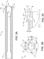
- sleeve 218 includes an external groove 250 that extends around bore 21; and, with further reference to Figures 2A-B and 3A , a plurality of channels 270 extend from a distal edge 250D of groove 250 to sleeve distal terminal end 218D, being formed in an outer surface of sleeve 218.
- FIG. 2A illustrates electrode assembly 202 including a steroid eluting component 25 seated within external groove 250 of sleeve 218; and Figure 2B illustrates electrode assembly 2021 including a steroid eluting component 27, which is also seated within external groove 250 but also has a portion thereof extending within at least one of channels 270.
- channels 270 provide fluid communication between steroid eluting component 25, 27 and an area distal to distal terminal end 218D of sleeve 218, which surrounds distal electrode 220.
- channels 270 can enhance the effectiveness of steroid elution from component 25, 27 to the implant site.
- Figure 3B is an end view of sleeve 218, according to some embodiments; and Figure 3C is an enlarged detail view of a portion of sleeve 218 in proximity to distal terminal end 218D, according to some embodiments.
- Figure 3B illustrates channels 270 uniformly spaced apart from one another around bore 21, wherein the spacing may be about sixty degrees.
- a width Wch of each channel 270 may be about 0.006 inch (0.1524mm) in some embodiments, and, with reference to Figure 3C , a floor 270f of one of channels 270 is shown angling toward bore 21 of sleeve 218 (or toward longitudinal axis 2 of assembly 202 that includes sleeve 218 as shown in Figures 2A-B ).
- floors 270f of some or all of channels 270 may be closer to bore 21, or axis 2, at sleeve distal terminal end 218D.
- the angling of channel floors 270f can facilitate the elution of steroid from component 25, 27 to a location closer to electrode 220 ( Figures 2A-B ).
- an angle ⁇ that defines the angling of channel floor 270f may be about 15 degrees
- a length Lc of each channel 270 may be about 0.010 inch (0.254mm)
- a depth Dg of groove 250 may be about 0.005 inch (0.127mm)
- a width Wg of groove 250 may be about 0.016 inch (0.4064mm).
- steroid eluting component 25, 27 is formed from a medical grade silicone rubber that is loaded with a steroid, for example, a 2-part enhanced tear resistant silicone rubber (dimethyl and methyl vinyl siloxane copolymers reinforced with silica) loaded with dexamethasone acetate steroid, wherein a percentage composition by weight of the steroid may range from about 25% to about 30%.
- Component 25 may be molded into the form of a ring, separate from sleeve 218, and then seated within groove 250, being bonded thereto with an adhesive (e.g., a silicone medical adhesive) for securement thereto, according to some embodiments.
- an adhesive e.g., a silicone medical adhesive
- component 25 has a wall thickness of about 0.005 inch (0.127mm) and a width Wco of about 0.014 inch (0.3556mm) to about 0.016 inch (0.406mm).
- component 25, 27 may be insert molded into groove 250 (and channels 270 for component 27), according to methods known in the art, such that the seating and bonding of component 25, 27 is accomplished during the insert molding process.
- an outer surface of component 25 is substantially flush with an outer surface of sleeve 218 on either side of groove 250 to maintain a substantially isodiametric profile of assembly 202, 2021.
- sleeve 218 is wholly formed from a medical grade polyurethane (e.g.
- groove 250 (and channels 270) can be plasma treated, according to methods known in the art, to enhance the surface(s) thereof for the bonding of component 25, 27 thereto.
- one or more additional channels 240 can extend through a floor 250f of groove 250, for example, to aid in the securement of component 25, 27 to sleeve 218 by allowing a flow of adhesive therethrough, or the flow of the material of component 25, 27 during molding, either of which can create a mechanical interlock between component 25, 27 and sleeve 218.
- channels 240 can also provide fluid communication between steroid eluting component 25, 27 and the area distal to sleeve distal terminal end 218D
- a diameter of each additional channel 240 may be about .010 inch (0.254mm).
- an inner surface 201 of sleeve 218, which defines sleeve bore 21, is formed so that the above described conductive coupling component 222 engages therewith, for example, being formed with flat portions, as seen in Figure 3B , to mate with flat portions 222f of coupling component 222 ( Figure 2C ).
- the engagement between sleeve 218 and conductive coupling component 222 which may be any suitable form of mechanical interlocking in addition to, or as an alternative to that described above, functions to prevent a rotation of distal electrode 220 relative to sleeve 218, for example, when an operator engages distal electrode 220 with myocardial tissue at the implant site by rotating electrode assembly 202 around axis 2 (e.g., by means of torque transferred through device body 214 from a proximal end thereof in proximity to connector 206).
- Figure 4 is a perspective view of electrode assembly 402, according to some additional embodiments, which may be incorporated in lead device 200 of Figure 1 .
- Figure 4 illustrates assembly 402 including a sleeve 418, which defines a longitudinal axis 4 of assembly 402, and which has a distal terminal end 418D from which distal electrode 220 extends.
- Figure 4 further illustrates electrode assembly 402 including a steroid eluting component 45, which is seated in, and secured to, an external groove 450 of sleeve 418, which can be seen in a longitudinal cross-section view of sleeve 418 shown in Figure 5A .
- Assembly 402 is similar in construction to that described above for assembly 202 ( Figure 2C ), but an inner surface of sleeve 418, which defines an elongate bore 41 of sleeve 418, has a plurality of channels 470 formed therein (rather than in an outer surface). With further reference to Figure 5A , additional channels 440 are shown extending through a floor 450f of groove 450 to provide fluid communication between groove 450 and channels 470, so that channels 470 essentially extend from groove 450 to sleeve distal terminal end 418D.
- channels 470 provide fluid communication between steroid eluting component 45 seated in groove 450 ( Figure 4 ) and an area distal to distal terminal end 418D of sleeve 418, which surrounds distal electrode 220.
- component 45 for example, formed from the same materials described above for components 25, 27, is insert molded into groove 450 and channels 440, and in some cases may further extend into at least one of channels 470.
- Figure 5B is an end view of sleeve 418, according to some embodiments; and Figure 5C is an enlarged detail view of a portion of sleeve distal terminal end 418D, according to some embodiments.
- Figure 5B illustrates channels 470 uniformly spaced apart from one another around bore 41, wherein, similar to channels 270 of sleeve 218, the spacing may be about sixty degrees, and a width Wch of each channel 470 may be about 0.006 inch (0.1524mm).
- a length Lc of each channel 470 may be about 0.010 inch (0.254mm), a depth Dg of groove 450 may be about 0.005 inch (0.127mm), and a diameter of each additional channel 440 may be about .010 inch (0.254mm).
- a dashed line indicates an optional angling for a floor of at least one of channels 470 toward longitudinal axis 4 of assembly 402 that includes sleeve 418.
- floors of some or all of channels 470 can be closer to axis 4, at sleeve distal terminal end 418D, for example, to facilitate the elution of steroid from component 45 to a location closer to electrode 220.
- the above described electrode assemblies 202, 2021, 402 may also include one of the aforementioned proximal electrodes 216, 716, wherein proximal electrode 216 ( Figure 2C ) is configured for delivery of defibrillation therapy, and proximal electrode 716 ( Figures 7A and 7C ) is configured for delivery of pacing therapy.
- proximal electrode 216 is shown being secured to sleeve 218 by means of a coupling component 620 mounted within sleeve bore 21 in proximity to a proximal end 218P thereof.
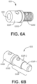
- Figure 6A is a perspective view of coupling component 620, according to some embodiments.
- Figure 6A illustrates component 620 including a proximal portion 620P, a distal portion 620D, and a shoulder 620S located therebetween.
- Coupling component 620 further includes an elongate bore 602, which extends along a length thereof to allow passage of insulated conductor 208 therethrough, as seen in Figure 2C.
- Figure 2C further illustrates coupling component proximal portion 620P extending proximally from sleeve proximal end 218P, and coupling component distal portion 620D being mounted within sleeve bore 21, for example, being secured to sleeve 218 by a bond that may be enhanced by threads formed along an outer surface of distal portion 620D.
- the bond between sleeve proximal end 218P and coupling component distal portion 620D may be formed by insert molding sleeve 218 over coupling component 620, or by using a polyurethane medical grade adhesive, wherein coupling component distal portion 620D may have a layer medical grade polyurethane formed thereover prior to forming the bond, when sleeve 218 is also formed from medical grade polyurethane.
- Proximal electrode 216 being suitable for the delivery of defibrillation therapy, is shown being formed by a coiled wire (e.g.
- a distance between sleeve distal terminal end 218D and proximal electrode distal end 216D may be about 0.45 inch (11 mm - 12 mm), and a length of proximal electrode 216 may range from about 2 inches to about 2.5 inches (51 mm - 63.5 mm).
- a proximal end 216P of proximal electrode 216 of electrode assembly 202 may be coupled to elongate insulated conductor 212 by means of another coupling component 630, a perspective view of which is shown in Figure 6B.
- Figure 6B illustrates the other coupling component 630 including a distal portion 630D, a stepped proximal portion 630P, and a shoulder 630S located therebetween.
- proximal electrode proximal end 216P is mounted around and coupled to distal portion 630D of the other coupling component 630, for example, by laser welding methods known in the art.
- a first surface 630P-1 of the other coupling component proximal portion 630P supports a distal end of a conductive coil of insulated conductor 212
- a second surface 630P-2 of the other coupling component proximal portion 630P supports an outer insulation tube 211 that surrounds the conductive coil of insulated conductor 212.
- FIG 7A is a perspective view of an electrode assembly 702 that includes distal electrode 220 and proximal electrode 716, which is suitable for the delivery of pacing therapy, according to some additional embodiments. It should be noted that electrode assembly 702 may be incorporated by lead 200, in lieu of assembly 202, in a similar manner to that described above in conjunction with Figure 2C .
- Figure 7A illustrates a sleeve 718 of assembly 702, which defines a longitudinal axis 7 of assembly 702, and which includes a distal terminal end 718D, from which distal electrode 220 extends, for example, having the aforementioned proximal end 220P thereof mounted within an elongate bore 71 of sleeve 718 where the aforementioned conductive coupling component 222 is secured thereto as shown in Figure 2C .
- FIG. 7A further illustrates electrode assembly 702 including the above-described steroid eluting component 25 that, similar to assembly 202, is seated in, and secured to, an external groove 750 of sleeve 718, which can be seen in the longitudinal cross-section view of sleeve 718 shown in Figure 7B .
- sleeve 718 further includes a plurality of channels 770 extending from a distal edge 750D of groove 750 to sleeve distal terminal end 718D so that channels 770 provide fluid communication between steroid eluting component 25 and an area distal to sleeve distal terminal end 718D, which surrounds distal electrode 220.
- Figure 7B further illustrates sleeve 718 including one or more additional channels 740 that extend through a floor 750f of groove 750.
- Steroid eluting component 25 may be seated in, and secured to, groove 750 according to any of the methods described above for assemblies 202, 2021, and exemplary dimensions for groove 750 and channels 770, 740 may be the same as those recited above for sleeve 218.
- Figures 7A-B show channels 770 being formed in an outer surface of sleeve 718, according to alternate embodiments of sleeve 718, channels 770 may be formed along an inner surface thereof like channels 470 of sleeve 418 ( Figure 4 ).
- floors of some or all of channels 770 may be angled as shown for channel floor 270f of sleeve 218 in Figure 3C .
- proximal electrode 716 of electrode assembly 702 may be in the form of a ring, being secured to a proximal end 718P of sleeve 718 by being mounted around an outer surface thereof.
- Figure 7B shows the outer surface of sleeve proximal end 718P being recessed so that an outer surface of mounted proximal electrode 716 may be flush with an adjacent outer surface of sleeve 718, according to some embodiments.
- Figure 7C is a perspective view of a component 730, which includes proximal electrode 716, according to some embodiments, and which may be constructed in a similar fashion to the above-described coupling component 630 that is employed in assembly 202 ( Figures 2C and 6B ).
- Figure 7C illustrates component 730 including a distal portion that forms proximal electrode 716 and a stepped proximal portion 730P, wherein a first surface 730P-1 of component proximal portion 730P supports a distal end of a conductive coil of an elongate insulated conductor (e.g.
- insulated conductor 212 of Figure 2C and a second surface 730P-2 of component proximal portion 730P supports an outer insulation tube that surrounds the conductive coil of the insulated conductor (e.g., tube 211 of Figure 2C ).
Landscapes
- Health & Medical Sciences (AREA)
- Engineering & Computer Science (AREA)
- Heart & Thoracic Surgery (AREA)
- Cardiology (AREA)
- Animal Behavior & Ethology (AREA)
- Biomedical Technology (AREA)
- Nuclear Medicine, Radiotherapy & Molecular Imaging (AREA)
- Radiology & Medical Imaging (AREA)
- Life Sciences & Earth Sciences (AREA)
- General Health & Medical Sciences (AREA)
- Public Health (AREA)
- Veterinary Medicine (AREA)
- Vascular Medicine (AREA)
- Medicinal Chemistry (AREA)
- Bioinformatics & Cheminformatics (AREA)
- Chemical & Material Sciences (AREA)
- Electrotherapy Devices (AREA)
Description
- The present disclosure pertains to implantable medical electrical devices suited for the delivery of cardiac therapy, and more particularly to electrode assemblies thereof.
- An implantable medical electrical system of the type suited for cardiac rhythm management typically includes a pulse generator device to which at least one flexible elongate lead device is coupled to deliver stimulation therapy from the pulse generator to the heart of a patient. The pulse generator device is typically implanted in a subcutaneous pocket, remote from the heart, and the lead device extends therefrom to a cardiac implant site, either endocardial or epicardial, at which an electrode of the lead is secured in intimate engagement with myocardial tissue, according to methods known in the art. Electrodes of this type, which may pierce the myocardial tissue at the implant site, are typically included in a device electrode assembly that has means to elute a steroid for the treatment of inflammation at the site. In one such electrode assembly, for example, as described in commonly assigned
United States Patent 7,184,839 , a helical screw with a piercing tip, which forms an electrode, has a coating with a microstructure, such as titanium nitride, that holds a steroid solution, such as Beclomethasone. In other types of electrode assemblies, a steroid solution is loaded into a polymer, such as silicone rubber, that is formed into a component and mounted in proximity to the electrode.US 5,522,874 A relates to a medical lead having a segmented electrode.US 5,002,067 A relates to a medical electrical lead employing an improved penetrating electrode.US 6,363,287 B1 relates to a steroid elution electrodes LCVC, left atrial medical/electrical leads. - Various embodiments of implantable electrode assemblies disclosed herein include a steroid eluting component and are configured to enhance the effectiveness of steroid elution from the component to the implant site.
- In particular,
claim 1 provides an electrode assembly for an implantable medical device. Further aspects and preferred embodiments are defined in the appended claims. Aspects, embodiments and examples of the present disclosure which do not fall under the scope of the appended claims do not form part of the claimed subject matter and are provided for illustrative purposes. Furthermore, the methods presented in the present description are not claimed as such but are useful for understanding the claimed subject matter. - A distal electrode of any of the assembly embodiments disclosed herein extends distally from a distal terminal end of a sleeve of the assembly, and the sleeve, which defines a longitudinal axis of the assembly, includes a plurality of channels that provide fluid communication between the steroid eluting component, which is seated in an external groove of the sleeve, and an area distal to the distal terminal end of the sleeve. According to some embodiments, floors of some or all of the plurality of sleeve channels angle toward the longitudinal axis of the assembly, being closer to the axis at the distal terminal end of the sleeve. Some assembly embodiments further include a proximal electrode secured to a proximal end of the sleeve, wherein the proximal electrode may be mounted around an outer surface of the sleeve or coupled to the sleeve by means of a coupling component.
- According to some embodiments of a device, which includes any one of the electrode assembly embodiments, an elongate insulated conductor couples the distal electrode to a connector of the device by means of a conductive coupling component of the electrode assembly, which is mounted within the sleeve bore, secured to a proximal portion of the distal electrode that extends within the sleeve bore, and which engages with an inner surface of the sleeve to prevent rotation of the distal electrode relative to the sleeve.
- The following drawings are illustrative of particular embodiments of the present disclosure and therefore do not limit the scope of the invention. The drawings are not to scale (unless so stated) and are intended for use in conjunction with the explanations in the following detailed description. Embodiments will hereinafter be described in conjunction with the appended drawings wherein like numerals denote like elements, and:
-
Figure 1 is a plan view of an exemplary implantable medical electrical lead device for cardiac stimulation, which may incorporate embodiments of the present invention; -
Figure 2A is a perspective view of an electrode assembly, according to some embodiments; -
Figure 2B is a perspective view of an electrode assembly, according to some alternate embodiments; -
Figure 2C is a longitudinal cross-section view of a portion of the lead device that includes the assembly ofFigure 2A , according to some embodiments; -
Figure 3A is a longitudinal cross-section view through a sleeve, according to some embodiments; -
Figure 3B is an end view of the sleeve ofFigure 3A , according to some embodiments; -
Figure 3C is an enlarged detail view of a portion of the sleeve ofFigure 3A , in proximity to a distal terminal end thereof, according to some embodiments; -
Figure 4 is a perspective view of an electrode assembly, according to some additional embodiments; -
Figure 5A is a longitudinal cross-section view through a sleeve of theFigure 4 electrode assembly, according to some of the additional embodiments; -
Figure 5B is an end view of the sleeve ofFigure 5A , according to some embodiments; -
Figure 5C is an enlarged detail view of a portion of the sleeve ofFigure 5A , in proximity to a distal terminal end thereof, according to some embodiments; -
Figure 6A is a perspective view of a coupling component, according to some embodiments; -
Figure 6B is a perspective view of another coupling component, according to some embodiments; -
Figure 7A is a perspective view of an electrode assembly that includes distal and proximal electrodes, according to some additional embodiments; -
Figure 7B is a longitudinal cross-section view of a sleeve of theFigure 7A electrode assembly, according to some embodiments; and -
Figure 7C is a perspective view of the proximal electrode of theFigure 7A assembly, according to some embodiments. - The following detailed description is exemplary in nature and is not intended to limit the scope, applicability, or configuration of the invention in any way. Rather, the following description provides practical examples, and those skilled in the art will recognize that some of the examples may have suitable alternatives.
-
Figure 1 is a plan view of an exemplary implantable medicalelectrical lead device 200 for cardiac stimulation, which may incorporate embodiments of the present invention, for example, any one ofelectrode assemblies Figure 1 illustrateslead device 200 including anelongate body 214 that extends proximally fromelectrode assembly connector 206 oflead device 200. According to the illustrated embodiment,electrode assembly distal electrode 220, which is coupled to aterminal pin contact 262 ofconnector 206 via an elongate insulated conductor 208 (Figure 2C ), and may further include aproximal electrode ring contact 258 ofconnector 206 via another elongate insulated conductor 212 (Figure 2C ).Insulated conductors body 214, which is known to those skilled in the art.Connector 206 is also constructed according to methods known in the art and is configured for connection to the aforementioned pulse generator device. An overall length oflead device 200 may be from about 25 inches (63.5cm) to about 40 inches (101.6cm), so that when the pulse generator device is implanted in a subcutaneous pocket, for example, formed in the pectoral region of a patient,lead device 200 can extend therefrom to reach a cardiac implant site at whichdistal electrode 220 is engaged with the myocardium.Figure 1 further illustrates ananchoring sleeve 204 mounted aroundbody 214 to facilitate a securement ofdevice body 214 in proximity to the pocket according to methods known to those skilled in the art. -
Figure 2A is a perspective view ofelectrode assembly 202, according to some embodiments; andFigure 2B is a perspective view ofelectrode assembly 2021, according to some alternate embodiments.Figures 2A-B illustrateelectrode assembly sleeve 218, which defines alongitudinal axis 2 ofassembly distal terminal end 218D from whichdistal electrode 220 extends. According to the illustrated embodiment,distal electrode 220 is formed from a helical wire (e.g. 90/10 platinum iridum (Pt/Ir) having a diameter of about 0.010 inch (0.254mm)) that has a piercing distal tip for engagement with the myocardium, a construction that is well known to those skilled in the art. With reference toFigure 2C , which is a longitudinal cross-section view of a portion oflead device 200 that includesassembly 202, aproximal portion 220P ofdistal electrode 220 is shown being mounted within anelongate bore 21 ofsleeve 218 where aconductive coupling component 222 is secured thereto, for example, via a laser weld.Figure 2C further illustrates the aforementioned insulatedconductor 208 being mechanically and electrically coupled tocoupling component 222, for example, via a crimp formed between aproximal barrel 222P ofcomponent 222 and a distal end 208D ofconductor 208, from which the insulation is removed. It should be understood thatelectrode assembly 2021 may also include the coupling betweendistal electrode 220 andconductor 208, viacomponent 222, as illustrated inFigure 2C . A similar mechanical and electrical coupling may be formed between a proximal end of conductor 208 (not shown) and the aforementionedterminal connector pin 262 of connector 206 (Figure 1 ). According to an exemplary embodiment, insulatedconductor 208 includes a 7x7 MP35N cable having an insulative coating of medical grade fluoropolymer, such as ethylene tetrafluoroethylene (ETFE), and may further include another layer of insulation in the form of a medical gradesilicone rubber tube 210 in which the coated cable extends, a construction which is known in the art. - With reference to a longitudinal cross-section view of
sleeve 218 inFigure 3A ,sleeve 218 includes anexternal groove 250 that extends aroundbore 21; and, with further reference toFigures 2A-B and3A , a plurality ofchannels 270 extend from adistal edge 250D ofgroove 250 to sleevedistal terminal end 218D, being formed in an outer surface ofsleeve 218.Figure 2A illustrateselectrode assembly 202 including asteroid eluting component 25 seated withinexternal groove 250 ofsleeve 218; andFigure 2B illustrateselectrode assembly 2021 including asteroid eluting component 27, which is also seated withinexternal groove 250 but also has a portion thereof extending within at least one ofchannels 270. In each of theFigures 2A-B embodiments,channels 270 provide fluid communication betweensteroid eluting component terminal end 218D ofsleeve 218, which surroundsdistal electrode 220. Thus, whenelectrode 220 is engaged with myocardium at the implant site,channels 270 can enhance the effectiveness of steroid elution fromcomponent -
Figure 3B is an end view ofsleeve 218, according to some embodiments; andFigure 3C is an enlarged detail view of a portion ofsleeve 218 in proximity to distalterminal end 218D, according to some embodiments.Figure 3B illustrateschannels 270 uniformly spaced apart from one another aroundbore 21, wherein the spacing may be about sixty degrees. A width Wch of eachchannel 270 may be about 0.006 inch (0.1524mm) in some embodiments, and, with reference toFigure 3C , afloor 270f of one ofchannels 270 is shown angling towardbore 21 of sleeve 218 (or towardlongitudinal axis 2 ofassembly 202 that includessleeve 218 as shown inFigures 2A-B ). Thus,floors 270f of some or all ofchannels 270 may be closer to bore 21, oraxis 2, at sleeve distalterminal end 218D. The angling ofchannel floors 270f can facilitate the elution of steroid fromcomponent Figures 2A-B ). With further reference toFigure 3C , according to an exemplary embodiment, an angle β that defines the angling ofchannel floor 270f may be about 15 degrees, a length Lc of eachchannel 270 may be about 0.010 inch (0.254mm), a depth Dg ofgroove 250 may be about 0.005 inch (0.127mm), and a width Wg ofgroove 250 may be about 0.016 inch (0.4064mm). - With further reference to
Figures 2A-B , according to some embodiments,steroid eluting component Component 25 may be molded into the form of a ring, separate fromsleeve 218, and then seated withingroove 250, being bonded thereto with an adhesive (e.g., a silicone medical adhesive) for securement thereto, according to some embodiments. In an exemplary embodiment,component 25 has a wall thickness of about 0.005 inch (0.127mm) and a width Wco of about 0.014 inch (0.3556mm) to about 0.016 inch (0.406mm). Alternately,component channels 270 for component 27), according to methods known in the art, such that the seating and bonding ofcomponent component 25 is substantially flush with an outer surface ofsleeve 218 on either side ofgroove 250 to maintain a substantially isodiametric profile ofassembly sleeve 218 is wholly formed from a medical grade polyurethane (e.g. having a hardness of about 55D), and in whichcomponent component Figure 2C and toFigure 3A , according to some embodiments, one or moreadditional channels 240 can extend through afloor 250f ofgroove 250, for example, to aid in the securement ofcomponent sleeve 218 by allowing a flow of adhesive therethrough, or the flow of the material ofcomponent component sleeve 218. In either case, one or more ofchannels 240 can also provide fluid communication betweensteroid eluting component terminal end 218D A diameter of eachadditional channel 240 may be about .010 inch (0.254mm). - With further reference to
Figures 3A-B , according to some embodiments, aninner surface 201 ofsleeve 218, which defines sleeve bore 21, is formed so that the above describedconductive coupling component 222 engages therewith, for example, being formed with flat portions, as seen inFigure 3B , to mate with flat portions 222f of coupling component 222 (Figure 2C ). The engagement betweensleeve 218 andconductive coupling component 222, which may be any suitable form of mechanical interlocking in addition to, or as an alternative to that described above, functions to prevent a rotation ofdistal electrode 220 relative tosleeve 218, for example, when an operator engagesdistal electrode 220 with myocardial tissue at the implant site by rotatingelectrode assembly 202 around axis 2 (e.g., by means of torque transferred throughdevice body 214 from a proximal end thereof in proximity to connector 206). -
Figure 4 is a perspective view ofelectrode assembly 402, according to some additional embodiments, which may be incorporated inlead device 200 ofFigure 1 .Figure 4 illustratesassembly 402 including asleeve 418, which defines a longitudinal axis 4 ofassembly 402, and which has a distalterminal end 418D from whichdistal electrode 220 extends.Figure 4 further illustrateselectrode assembly 402 including asteroid eluting component 45, which is seated in, and secured to, anexternal groove 450 ofsleeve 418, which can be seen in a longitudinal cross-section view ofsleeve 418 shown inFigure 5A .Assembly 402 is similar in construction to that described above for assembly 202 (Figure 2C ), but an inner surface ofsleeve 418, which defines anelongate bore 41 ofsleeve 418, has a plurality ofchannels 470 formed therein (rather than in an outer surface). With further reference toFigure 5A ,additional channels 440 are shown extending through afloor 450f ofgroove 450 to provide fluid communication betweengroove 450 andchannels 470, so thatchannels 470 essentially extend fromgroove 450 to sleeve distalterminal end 418D. Thus,channels 470 provide fluid communication betweensteroid eluting component 45 seated in groove 450 (Figure 4 ) and an area distal to distalterminal end 418D ofsleeve 418, which surroundsdistal electrode 220. According to someembodiments component 45, for example, formed from the same materials described above forcomponents groove 450 andchannels 440, and in some cases may further extend into at least one ofchannels 470. -
Figure 5B is an end view ofsleeve 418, according to some embodiments; andFigure 5C is an enlarged detail view of a portion of sleeve distalterminal end 418D, according to some embodiments.Figure 5B illustrateschannels 470 uniformly spaced apart from one another around bore 41, wherein, similar tochannels 270 ofsleeve 218, the spacing may be about sixty degrees, and a width Wch of eachchannel 470 may be about 0.006 inch (0.1524mm). According to an exemplary embodiment, as insleeve 218, a length Lc of eachchannel 470 may be about 0.010 inch (0.254mm), a depth Dg ofgroove 450 may be about 0.005 inch (0.127mm), and a diameter of eachadditional channel 440 may be about .010 inch (0.254mm). With reference toFigure 5C , a dashed line indicates an optional angling for a floor of at least one ofchannels 470 toward longitudinal axis 4 ofassembly 402 that includessleeve 418. Thus, floors of some or all ofchannels 470 can be closer to axis 4, at sleeve distalterminal end 418D, for example, to facilitate the elution of steroid fromcomponent 45 to a location closer toelectrode 220. - With reference back to
Figure 1 , the above describedelectrode assemblies proximal electrodes Figure 2C ) is configured for delivery of defibrillation therapy, and proximal electrode 716 (Figures 7A and 7C ) is configured for delivery of pacing therapy. With reference toFigure 2C ,proximal electrode 216 is shown being secured tosleeve 218 by means of acoupling component 620 mounted within sleeve bore 21 in proximity to aproximal end 218P thereof. -
Figure 6A is a perspective view ofcoupling component 620, according to some embodiments.Figure 6A illustratescomponent 620 including aproximal portion 620P, adistal portion 620D, and ashoulder 620S located therebetween.Coupling component 620 further includes anelongate bore 602, which extends along a length thereof to allow passage ofinsulated conductor 208 therethrough, as seen inFigure 2C. Figure 2C further illustrates coupling componentproximal portion 620P extending proximally from sleeveproximal end 218P, and coupling componentdistal portion 620D being mounted within sleeve bore 21, for example, being secured tosleeve 218 by a bond that may be enhanced by threads formed along an outer surface ofdistal portion 620D. The bond between sleeveproximal end 218P and coupling componentdistal portion 620D may be formed byinsert molding sleeve 218 overcoupling component 620, or by using a polyurethane medical grade adhesive, wherein coupling componentdistal portion 620D may have a layer medical grade polyurethane formed thereover prior to forming the bond, whensleeve 218 is also formed from medical grade polyurethane.Proximal electrode 216, being suitable for the delivery of defibrillation therapy, is shown being formed by a coiled wire (e.g. 90/10 Pt/Ir or tantalum wire having a rectangular cross-section), and having adistal end 216D mounted around, and coupled to coupling componentproximal portion 620P, for example, by laser welding methods known in the art. According to an exemplary embodiment, a distance between sleeve distalterminal end 218D and proximal electrodedistal end 216D may be about 0.45 inch (11 mm - 12 mm), and a length ofproximal electrode 216 may range from about 2 inches to about 2.5 inches (51 mm - 63.5 mm). - With further reference to
Figure 2C , a proximal end 216P ofproximal electrode 216 ofelectrode assembly 202 may be coupled to elongateinsulated conductor 212 by means of anothercoupling component 630, a perspective view of which is shown inFigure 6B. Figure 6B illustrates theother coupling component 630 including adistal portion 630D, a steppedproximal portion 630P, and ashoulder 630S located therebetween. With reference toFigure 2C , proximal electrode proximal end 216P is mounted around and coupled todistal portion 630D of theother coupling component 630, for example, by laser welding methods known in the art. With reference toFigure 6B in conjunction withFigure 2C , afirst surface 630P-1 of the other coupling componentproximal portion 630P supports a distal end of a conductive coil ofinsulated conductor 212, and asecond surface 630P-2 of the other coupling componentproximal portion 630P supports anouter insulation tube 211 that surrounds the conductive coil ofinsulated conductor 212. -
Figure 7A is a perspective view of anelectrode assembly 702 that includesdistal electrode 220 andproximal electrode 716, which is suitable for the delivery of pacing therapy, according to some additional embodiments. It should be noted thatelectrode assembly 702 may be incorporated bylead 200, in lieu ofassembly 202, in a similar manner to that described above in conjunction withFigure 2C .Figure 7A illustrates asleeve 718 ofassembly 702, which defines a longitudinal axis 7 ofassembly 702, and which includes a distalterminal end 718D, from whichdistal electrode 220 extends, for example, having the aforementionedproximal end 220P thereof mounted within anelongate bore 71 ofsleeve 718 where the aforementionedconductive coupling component 222 is secured thereto as shown inFigure 2C .Figure 7A further illustrateselectrode assembly 702 including the above-describedsteroid eluting component 25 that, similar toassembly 202, is seated in, and secured to, anexternal groove 750 ofsleeve 718, which can be seen in the longitudinal cross-section view ofsleeve 718 shown inFigure 7B . With reference toFigures 7A-B ,sleeve 718 further includes a plurality ofchannels 770 extending from adistal edge 750D ofgroove 750 to sleeve distalterminal end 718D so thatchannels 770 provide fluid communication betweensteroid eluting component 25 and an area distal to sleeve distalterminal end 718D, which surroundsdistal electrode 220.Figure 7B further illustratessleeve 718 including one or moreadditional channels 740 that extend through afloor 750f ofgroove 750.Steroid eluting component 25 may be seated in, and secured to, groove 750 according to any of the methods described above forassemblies groove 750 andchannels sleeve 218. AlthoughFigures 7A- B show channels 770 being formed in an outer surface ofsleeve 718, according to alternate embodiments ofsleeve 718,channels 770 may be formed along an inner surface thereof likechannels 470 of sleeve 418 (Figure 4 ). Furthermore, according to some embodiments, floors of some or all ofchannels 770 may be angled as shown forchannel floor 270f ofsleeve 218 inFigure 3C . - With further reference to
Figures 7A-B ,proximal electrode 716 ofelectrode assembly 702 may be in the form of a ring, being secured to aproximal end 718P ofsleeve 718 by being mounted around an outer surface thereof.Figure 7B shows the outer surface of sleeveproximal end 718P being recessed so that an outer surface of mountedproximal electrode 716 may be flush with an adjacent outer surface ofsleeve 718, according to some embodiments.Figure 7C is a perspective view of acomponent 730, which includesproximal electrode 716, according to some embodiments, and which may be constructed in a similar fashion to the above-describedcoupling component 630 that is employed in assembly 202 (Figures 2C and6B ).Figure 7C illustratescomponent 730 including a distal portion that formsproximal electrode 716 and a steppedproximal portion 730P, wherein afirst surface 730P-1 of componentproximal portion 730P supports a distal end of a conductive coil of an elongate insulated conductor (e.g.insulated conductor 212 ofFigure 2C ), and asecond surface 730P-2 of componentproximal portion 730P supports an outer insulation tube that surrounds the conductive coil of the insulated conductor (e.g.,tube 211 ofFigure 2C ).
Claims (14)
- An electrode assembly for an implantable medical device, the assembly comprising:a sleeve (218) defining a longitudinal axis (2) of the assembly, the sleeve comprising a distal terminal end (218D), an elongate bore (21) extending along the axis proximally from a distal opening thereof at the distal terminal end, an external groove (250) extending around the bore, and a plurality of channels (270), each channel of the plurality extending from the groove to the distal terminal end;a distal electrode (220) secured to the sleeve and extending distally from the distal terminal end of the sleeve;a steroid eluting component (25) seated within the external groove of the sleeve and being secured thereto; andwherein, the plurality of channels of the sleeve provide fluid communication between the steroid eluting component and an area distal to the distal terminal end of the sleeve.
- The assembly of claim 1, wherein some or all of the plurality of sleeve channels extend from a distal edge of the sleeve groove.
- The assembly of any of claims 1-2, wherein at least one channel of the plurality of sleeve channels extends through a floor (250f) of the sleeve groove.
- The assembly of any of claims 1-3, wherein a portion of the steroid eluting component extends within at least one of the plurality of sleeve channels.
- The assembly of any of claims 1-4, wherein some or all of the plurality of sleeve channels are formed in an outer surface of the sleeve.
- The assembly of any of claims 1-5, wherein some or all of the plurality of sleeve channels are formed in an inner surface of the sleeve, the inner surface defining the sleeve bore.
- The assembly of any of claims 1-6, wherein floors of some or all of the plurality of sleeve channels angle toward the longitudinal axis of the assembly, being closer to the axis at the distal terminal end of the sleeve.
- The assembly of any of claims 1-7, wherein some or all of the plurality of sleeve channels are uniformly spaced apart from one another around the sleeve bore, the uniform spacing being about 60 degrees.
- The assembly of any of claims 1-8, further comprising a conductive coupling component (222) mounted within the sleeve bore and being secured to a proximal portion of the distal electrode that extends within the bore of the sleeve, and wherein the coupling component engages with an inner surface of the sleeve to prevent rotation of the distal electrode relative to the sleeve, the inner surface defining the sleeve bore.
- The assembly of any of claims 1-9, wherein the sleeve is wholly formed from an insulative material.
- The assembly of claim 10, further comprising a proximal electrode secured to a proximal end of the sleeve.
- The assembly of claim 11, wherein the proximal electrode (716) comprises a ring mounted around an outer surface of the sleeve.
- The assembly of claim 11, further comprising a coupling component (620) mounted within the sleeve bore, in proximity to the proximal end of the sleeve, the coupling component securing the proximal electrode to the sleeve.
- The assembly of claim 13, wherein:the coupling component comprises a proximal portion and a distal portion, the distal portion of the coupling component being mounted within the sleeve bore, and the proximal portion of the coupling component extending proximally from the proximal end of the sleeve; andthe proximal electrode comprises an elongate coil having a distal end coupled to the proximal portion of the coupling component.
Applications Claiming Priority (3)
| Application Number | Priority Date | Filing Date | Title |
|---|---|---|---|
| US201862646142P | 2018-03-21 | 2018-03-21 | |
| US16/357,813 US11020587B2 (en) | 2018-03-21 | 2019-03-19 | Implantable medical electrode assemblies and associated devices and methods |
| PCT/US2019/023177 WO2019183229A1 (en) | 2018-03-21 | 2019-03-20 | Implantable medical electrode assemblies |
Publications (2)
| Publication Number | Publication Date |
|---|---|
| EP3768368A1 EP3768368A1 (en) | 2021-01-27 |
| EP3768368B1 true EP3768368B1 (en) | 2024-02-21 |
Family
ID=67983978
Family Applications (1)
| Application Number | Title | Priority Date | Filing Date |
|---|---|---|---|
| EP19715645.8A Active EP3768368B1 (en) | 2018-03-21 | 2019-03-20 | Implantable medical electrode assemblies |
Country Status (4)
| Country | Link |
|---|---|
| US (1) | US11020587B2 (en) |
| EP (1) | EP3768368B1 (en) |
| CN (1) | CN111727072B (en) |
| WO (1) | WO2019183229A1 (en) |
Family Cites Families (12)
| Publication number | Priority date | Publication date | Assignee | Title |
|---|---|---|---|---|
| US5002067A (en) | 1989-08-23 | 1991-03-26 | Medtronic, Inc. | Medical electrical lead employing improved penetrating electrode |
| US5522874A (en) | 1994-07-28 | 1996-06-04 | Gates; James T. | Medical lead having segmented electrode |
| US6801809B2 (en) | 2000-02-22 | 2004-10-05 | Medtronic, Inc. | Extractable implantable medical lead |
| US6198973B1 (en) | 1999-05-26 | 2001-03-06 | Pacesetter, Inc. | Integrated steroid eluting pacing tip electrode |
| US6363287B1 (en) | 1999-10-27 | 2002-03-26 | Medtronic, Inc. | Steroid elution electrodes LVCV, left atrial medical/elecrical leads |
| US7184839B2 (en) | 2002-12-16 | 2007-02-27 | Medtronic, Inc. | Catheter-delivered cardiac lead |
| CN101711125B (en) * | 2007-04-18 | 2016-03-16 | 美敦力公司 | Long-term implantable active fixed medical electronic leads for non-fluoroscopy implants |
| WO2011081699A1 (en) * | 2009-12-30 | 2011-07-07 | Cardiac Pacemakers, Inc. | Tapered drug-eluting collar for a medical electrical lead |
| US8478429B2 (en) * | 2010-12-28 | 2013-07-02 | Cardiac Pacemakers, Inc. | Extendable/retractable fixation lead with distal travelling seal and related devices |
| US8424388B2 (en) * | 2011-01-28 | 2013-04-23 | Medtronic, Inc. | Implantable capacitive pressure sensor apparatus and methods regarding same |
| US9119959B2 (en) * | 2013-07-31 | 2015-09-01 | Medtronic, Inc. | Tine fixation components for implantable medical devices |
| US10315028B2 (en) * | 2014-04-23 | 2019-06-11 | Medtronic, Inc. | Active fixation medical electrical lead |
-
2019
- 2019-03-19 US US16/357,813 patent/US11020587B2/en active Active
- 2019-03-20 EP EP19715645.8A patent/EP3768368B1/en active Active
- 2019-03-20 WO PCT/US2019/023177 patent/WO2019183229A1/en not_active Ceased
- 2019-03-20 CN CN201980013850.6A patent/CN111727072B/en active Active
Also Published As
| Publication number | Publication date |
|---|---|
| WO2019183229A1 (en) | 2019-09-26 |
| CN111727072A (en) | 2020-09-29 |
| EP3768368A1 (en) | 2021-01-27 |
| US11020587B2 (en) | 2021-06-01 |
| CN111727072B (en) | 2024-11-22 |
| US20190290899A1 (en) | 2019-09-26 |
Similar Documents
| Publication | Publication Date | Title |
|---|---|---|
| US12551695B2 (en) | Tube-cut helical fixation anchor for electrotherapy device | |
| EP2195078B1 (en) | Implantable medical lead with biased electrode | |
| US7860580B2 (en) | Active fixation medical electrical lead | |
| US6263250B1 (en) | Ring electrode with porous member | |
| EP1481706A1 (en) | Fixation of a left heart medical lead in the coronary sinus | |
| US6701191B2 (en) | Lead having composite tubing | |
| US7711437B1 (en) | Lead fixation device | |
| US20030093136A1 (en) | Cardiac lead with steroid eluting ring | |
| US20030199951A1 (en) | Implantable lead with improved conductor lumens | |
| US6606522B2 (en) | Torque mechanism and method for endocardial leads | |
| US20140031661A1 (en) | Temporary implantable medical electrical stimulation lead | |
| US20050065588A1 (en) | Medical electrical lead system including pre-formed J-shape stylet | |
| US7191017B1 (en) | Two-part implantable cardiac lead | |
| EP3870268B1 (en) | Configurations and constructions for active fixation implantable medical electrical leads | |
| US11020587B2 (en) | Implantable medical electrode assemblies and associated devices and methods | |
| EP4467187B1 (en) | Biostimulator having a strain-relieved pacing element |
Legal Events
| Date | Code | Title | Description |
|---|---|---|---|
| STAA | Information on the status of an ep patent application or granted ep patent |
Free format text: STATUS: UNKNOWN |
|
| STAA | Information on the status of an ep patent application or granted ep patent |
Free format text: STATUS: THE INTERNATIONAL PUBLICATION HAS BEEN MADE |
|
| PUAI | Public reference made under article 153(3) epc to a published international application that has entered the european phase |
Free format text: ORIGINAL CODE: 0009012 |
|
| STAA | Information on the status of an ep patent application or granted ep patent |
Free format text: STATUS: REQUEST FOR EXAMINATION WAS MADE |
|
| 17P | Request for examination filed |
Effective date: 20201021 |
|
| AK | Designated contracting states |
Kind code of ref document: A1 Designated state(s): AL AT BE BG CH CY CZ DE DK EE ES FI FR GB GR HR HU IE IS IT LI LT LU LV MC MK MT NL NO PL PT RO RS SE SI SK SM TR |
|
| AX | Request for extension of the european patent |
Extension state: BA ME |
|
| DAV | Request for validation of the european patent (deleted) | ||
| DAX | Request for extension of the european patent (deleted) | ||
| STAA | Information on the status of an ep patent application or granted ep patent |
Free format text: STATUS: EXAMINATION IS IN PROGRESS |
|
| 17Q | First examination report despatched |
Effective date: 20221013 |
|
| GRAP | Despatch of communication of intention to grant a patent |
Free format text: ORIGINAL CODE: EPIDOSNIGR1 |
|
| STAA | Information on the status of an ep patent application or granted ep patent |
Free format text: STATUS: GRANT OF PATENT IS INTENDED |
|
| INTG | Intention to grant announced |
Effective date: 20230503 |
|
| GRAJ | Information related to disapproval of communication of intention to grant by the applicant or resumption of examination proceedings by the epo deleted |
Free format text: ORIGINAL CODE: EPIDOSDIGR1 |
|
| STAA | Information on the status of an ep patent application or granted ep patent |
Free format text: STATUS: EXAMINATION IS IN PROGRESS |
|
| GRAP | Despatch of communication of intention to grant a patent |
Free format text: ORIGINAL CODE: EPIDOSNIGR1 |
|
| STAA | Information on the status of an ep patent application or granted ep patent |
Free format text: STATUS: GRANT OF PATENT IS INTENDED |
|
| INTC | Intention to grant announced (deleted) | ||
| INTG | Intention to grant announced |
Effective date: 20230922 |
|
| GRAS | Grant fee paid |
Free format text: ORIGINAL CODE: EPIDOSNIGR3 |
|
| GRAA | (expected) grant |
Free format text: ORIGINAL CODE: 0009210 |
|
| STAA | Information on the status of an ep patent application or granted ep patent |
Free format text: STATUS: THE PATENT HAS BEEN GRANTED |
|
| AK | Designated contracting states |
Kind code of ref document: B1 Designated state(s): AL AT BE BG CH CY CZ DE DK EE ES FI FR GB GR HR HU IE IS IT LI LT LU LV MC MK MT NL NO PL PT RO RS SE SI SK SM TR |
|
| REG | Reference to a national code |
Ref country code: GB Ref legal event code: FG4D |
|
| REG | Reference to a national code |
Ref country code: CH Ref legal event code: EP |
|
| REG | Reference to a national code |
Ref country code: IE Ref legal event code: FG4D |
|
| REG | Reference to a national code |
Ref country code: DE Ref legal event code: R096 Ref document number: 602019046877 Country of ref document: DE |
|
| REG | Reference to a national code |
Ref country code: LT Ref legal event code: MG9D |
|
| REG | Reference to a national code |
Ref country code: NL Ref legal event code: MP Effective date: 20240221 |
|
| PG25 | Lapsed in a contracting state [announced via postgrant information from national office to epo] |
Ref country code: IS Free format text: LAPSE BECAUSE OF FAILURE TO SUBMIT A TRANSLATION OF THE DESCRIPTION OR TO PAY THE FEE WITHIN THE PRESCRIBED TIME-LIMIT Effective date: 20240621 |
|
| PG25 | Lapsed in a contracting state [announced via postgrant information from national office to epo] |
Ref country code: LT Free format text: LAPSE BECAUSE OF FAILURE TO SUBMIT A TRANSLATION OF THE DESCRIPTION OR TO PAY THE FEE WITHIN THE PRESCRIBED TIME-LIMIT Effective date: 20240221 |
|
| PG25 | Lapsed in a contracting state [announced via postgrant information from national office to epo] |
Ref country code: GR Free format text: LAPSE BECAUSE OF FAILURE TO SUBMIT A TRANSLATION OF THE DESCRIPTION OR TO PAY THE FEE WITHIN THE PRESCRIBED TIME-LIMIT Effective date: 20240522 |
|
| REG | Reference to a national code |
Ref country code: AT Ref legal event code: MK05 Ref document number: 1658585 Country of ref document: AT Kind code of ref document: T Effective date: 20240221 |
|
| PG25 | Lapsed in a contracting state [announced via postgrant information from national office to epo] |
Ref country code: NL Free format text: LAPSE BECAUSE OF FAILURE TO SUBMIT A TRANSLATION OF THE DESCRIPTION OR TO PAY THE FEE WITHIN THE PRESCRIBED TIME-LIMIT Effective date: 20240221 Ref country code: RS Free format text: LAPSE BECAUSE OF FAILURE TO SUBMIT A TRANSLATION OF THE DESCRIPTION OR TO PAY THE FEE WITHIN THE PRESCRIBED TIME-LIMIT Effective date: 20240521 Ref country code: HR Free format text: LAPSE BECAUSE OF FAILURE TO SUBMIT A TRANSLATION OF THE DESCRIPTION OR TO PAY THE FEE WITHIN THE PRESCRIBED TIME-LIMIT Effective date: 20240221 |
|
| PG25 | Lapsed in a contracting state [announced via postgrant information from national office to epo] |
Ref country code: ES Free format text: LAPSE BECAUSE OF FAILURE TO SUBMIT A TRANSLATION OF THE DESCRIPTION OR TO PAY THE FEE WITHIN THE PRESCRIBED TIME-LIMIT Effective date: 20240221 |
|
| PG25 | Lapsed in a contracting state [announced via postgrant information from national office to epo] |
Ref country code: AT Free format text: LAPSE BECAUSE OF FAILURE TO SUBMIT A TRANSLATION OF THE DESCRIPTION OR TO PAY THE FEE WITHIN THE PRESCRIBED TIME-LIMIT Effective date: 20240221 |
|
| PG25 | Lapsed in a contracting state [announced via postgrant information from national office to epo] |
Ref country code: RS Free format text: LAPSE BECAUSE OF FAILURE TO SUBMIT A TRANSLATION OF THE DESCRIPTION OR TO PAY THE FEE WITHIN THE PRESCRIBED TIME-LIMIT Effective date: 20240521 Ref country code: NO Free format text: LAPSE BECAUSE OF FAILURE TO SUBMIT A TRANSLATION OF THE DESCRIPTION OR TO PAY THE FEE WITHIN THE PRESCRIBED TIME-LIMIT Effective date: 20240521 Ref country code: NL Free format text: LAPSE BECAUSE OF FAILURE TO SUBMIT A TRANSLATION OF THE DESCRIPTION OR TO PAY THE FEE WITHIN THE PRESCRIBED TIME-LIMIT Effective date: 20240221 Ref country code: LT Free format text: LAPSE BECAUSE OF FAILURE TO SUBMIT A TRANSLATION OF THE DESCRIPTION OR TO PAY THE FEE WITHIN THE PRESCRIBED TIME-LIMIT Effective date: 20240221 Ref country code: IS Free format text: LAPSE BECAUSE OF FAILURE TO SUBMIT A TRANSLATION OF THE DESCRIPTION OR TO PAY THE FEE WITHIN THE PRESCRIBED TIME-LIMIT Effective date: 20240621 Ref country code: HR Free format text: LAPSE BECAUSE OF FAILURE TO SUBMIT A TRANSLATION OF THE DESCRIPTION OR TO PAY THE FEE WITHIN THE PRESCRIBED TIME-LIMIT Effective date: 20240221 Ref country code: GR Free format text: LAPSE BECAUSE OF FAILURE TO SUBMIT A TRANSLATION OF THE DESCRIPTION OR TO PAY THE FEE WITHIN THE PRESCRIBED TIME-LIMIT Effective date: 20240522 Ref country code: FI Free format text: LAPSE BECAUSE OF FAILURE TO SUBMIT A TRANSLATION OF THE DESCRIPTION OR TO PAY THE FEE WITHIN THE PRESCRIBED TIME-LIMIT Effective date: 20240221 Ref country code: ES Free format text: LAPSE BECAUSE OF FAILURE TO SUBMIT A TRANSLATION OF THE DESCRIPTION OR TO PAY THE FEE WITHIN THE PRESCRIBED TIME-LIMIT Effective date: 20240221 Ref country code: BG Free format text: LAPSE BECAUSE OF FAILURE TO SUBMIT A TRANSLATION OF THE DESCRIPTION OR TO PAY THE FEE WITHIN THE PRESCRIBED TIME-LIMIT Effective date: 20240221 Ref country code: AT Free format text: LAPSE BECAUSE OF FAILURE TO SUBMIT A TRANSLATION OF THE DESCRIPTION OR TO PAY THE FEE WITHIN THE PRESCRIBED TIME-LIMIT Effective date: 20240221 |
|
| PG25 | Lapsed in a contracting state [announced via postgrant information from national office to epo] |
Ref country code: PL Free format text: LAPSE BECAUSE OF FAILURE TO SUBMIT A TRANSLATION OF THE DESCRIPTION OR TO PAY THE FEE WITHIN THE PRESCRIBED TIME-LIMIT Effective date: 20240221 Ref country code: PT Free format text: LAPSE BECAUSE OF FAILURE TO SUBMIT A TRANSLATION OF THE DESCRIPTION OR TO PAY THE FEE WITHIN THE PRESCRIBED TIME-LIMIT Effective date: 20240621 |
|
| PG25 | Lapsed in a contracting state [announced via postgrant information from national office to epo] |
Ref country code: SE Free format text: LAPSE BECAUSE OF FAILURE TO SUBMIT A TRANSLATION OF THE DESCRIPTION OR TO PAY THE FEE WITHIN THE PRESCRIBED TIME-LIMIT Effective date: 20240221 Ref country code: PT Free format text: LAPSE BECAUSE OF FAILURE TO SUBMIT A TRANSLATION OF THE DESCRIPTION OR TO PAY THE FEE WITHIN THE PRESCRIBED TIME-LIMIT Effective date: 20240621 Ref country code: PL Free format text: LAPSE BECAUSE OF FAILURE TO SUBMIT A TRANSLATION OF THE DESCRIPTION OR TO PAY THE FEE WITHIN THE PRESCRIBED TIME-LIMIT Effective date: 20240221 Ref country code: LV Free format text: LAPSE BECAUSE OF FAILURE TO SUBMIT A TRANSLATION OF THE DESCRIPTION OR TO PAY THE FEE WITHIN THE PRESCRIBED TIME-LIMIT Effective date: 20240221 |
|
| PG25 | Lapsed in a contracting state [announced via postgrant information from national office to epo] |
Ref country code: DK Free format text: LAPSE BECAUSE OF FAILURE TO SUBMIT A TRANSLATION OF THE DESCRIPTION OR TO PAY THE FEE WITHIN THE PRESCRIBED TIME-LIMIT Effective date: 20240221 |
|
| PG25 | Lapsed in a contracting state [announced via postgrant information from national office to epo] |
Ref country code: SM Free format text: LAPSE BECAUSE OF FAILURE TO SUBMIT A TRANSLATION OF THE DESCRIPTION OR TO PAY THE FEE WITHIN THE PRESCRIBED TIME-LIMIT Effective date: 20240221 |
|
| PG25 | Lapsed in a contracting state [announced via postgrant information from national office to epo] |
Ref country code: EE Free format text: LAPSE BECAUSE OF FAILURE TO SUBMIT A TRANSLATION OF THE DESCRIPTION OR TO PAY THE FEE WITHIN THE PRESCRIBED TIME-LIMIT Effective date: 20240221 Ref country code: CZ Free format text: LAPSE BECAUSE OF FAILURE TO SUBMIT A TRANSLATION OF THE DESCRIPTION OR TO PAY THE FEE WITHIN THE PRESCRIBED TIME-LIMIT Effective date: 20240221 |
|
| PG25 | Lapsed in a contracting state [announced via postgrant information from national office to epo] |
Ref country code: SK Free format text: LAPSE BECAUSE OF FAILURE TO SUBMIT A TRANSLATION OF THE DESCRIPTION OR TO PAY THE FEE WITHIN THE PRESCRIBED TIME-LIMIT Effective date: 20240221 |
|
| PG25 | Lapsed in a contracting state [announced via postgrant information from national office to epo] |
Ref country code: SM Free format text: LAPSE BECAUSE OF FAILURE TO SUBMIT A TRANSLATION OF THE DESCRIPTION OR TO PAY THE FEE WITHIN THE PRESCRIBED TIME-LIMIT Effective date: 20240221 Ref country code: SK Free format text: LAPSE BECAUSE OF FAILURE TO SUBMIT A TRANSLATION OF THE DESCRIPTION OR TO PAY THE FEE WITHIN THE PRESCRIBED TIME-LIMIT Effective date: 20240221 Ref country code: RO Free format text: LAPSE BECAUSE OF FAILURE TO SUBMIT A TRANSLATION OF THE DESCRIPTION OR TO PAY THE FEE WITHIN THE PRESCRIBED TIME-LIMIT Effective date: 20240221 Ref country code: EE Free format text: LAPSE BECAUSE OF FAILURE TO SUBMIT A TRANSLATION OF THE DESCRIPTION OR TO PAY THE FEE WITHIN THE PRESCRIBED TIME-LIMIT Effective date: 20240221 Ref country code: DK Free format text: LAPSE BECAUSE OF FAILURE TO SUBMIT A TRANSLATION OF THE DESCRIPTION OR TO PAY THE FEE WITHIN THE PRESCRIBED TIME-LIMIT Effective date: 20240221 Ref country code: CZ Free format text: LAPSE BECAUSE OF FAILURE TO SUBMIT A TRANSLATION OF THE DESCRIPTION OR TO PAY THE FEE WITHIN THE PRESCRIBED TIME-LIMIT Effective date: 20240221 |
|
| REG | Reference to a national code |
Ref country code: CH Ref legal event code: PL |
|
| PG25 | Lapsed in a contracting state [announced via postgrant information from national office to epo] |
Ref country code: LU Free format text: LAPSE BECAUSE OF NON-PAYMENT OF DUE FEES Effective date: 20240320 |
|
| PG25 | Lapsed in a contracting state [announced via postgrant information from national office to epo] |
Ref country code: MC Free format text: LAPSE BECAUSE OF FAILURE TO SUBMIT A TRANSLATION OF THE DESCRIPTION OR TO PAY THE FEE WITHIN THE PRESCRIBED TIME-LIMIT Effective date: 20240221 |
|
| REG | Reference to a national code |
Ref country code: DE Ref legal event code: R097 Ref document number: 602019046877 Country of ref document: DE |
|
| PG25 | Lapsed in a contracting state [announced via postgrant information from national office to epo] |
Ref country code: MC Free format text: LAPSE BECAUSE OF FAILURE TO SUBMIT A TRANSLATION OF THE DESCRIPTION OR TO PAY THE FEE WITHIN THE PRESCRIBED TIME-LIMIT Effective date: 20240221 Ref country code: LU Free format text: LAPSE BECAUSE OF NON-PAYMENT OF DUE FEES Effective date: 20240320 |
|
| PG25 | Lapsed in a contracting state [announced via postgrant information from national office to epo] |
Ref country code: IT Free format text: LAPSE BECAUSE OF FAILURE TO SUBMIT A TRANSLATION OF THE DESCRIPTION OR TO PAY THE FEE WITHIN THE PRESCRIBED TIME-LIMIT Effective date: 20240221 |
|
| REG | Reference to a national code |
Ref country code: BE Ref legal event code: MM Effective date: 20240331 |
|
| PLBE | No opposition filed within time limit |
Free format text: ORIGINAL CODE: 0009261 |
|
| STAA | Information on the status of an ep patent application or granted ep patent |
Free format text: STATUS: NO OPPOSITION FILED WITHIN TIME LIMIT |
|
| PG25 | Lapsed in a contracting state [announced via postgrant information from national office to epo] |
Ref country code: IT Free format text: LAPSE BECAUSE OF FAILURE TO SUBMIT A TRANSLATION OF THE DESCRIPTION OR TO PAY THE FEE WITHIN THE PRESCRIBED TIME-LIMIT Effective date: 20240221 |
|
| PG25 | Lapsed in a contracting state [announced via postgrant information from national office to epo] |
Ref country code: BE Free format text: LAPSE BECAUSE OF NON-PAYMENT OF DUE FEES Effective date: 20240331 |
|
| PG25 | Lapsed in a contracting state [announced via postgrant information from national office to epo] |
Ref country code: IE Free format text: LAPSE BECAUSE OF NON-PAYMENT OF DUE FEES Effective date: 20240320 |
|
| 26N | No opposition filed |
Effective date: 20241122 |
|
| GBPC | Gb: european patent ceased through non-payment of renewal fee |
Effective date: 20240521 |
|
| PG25 | Lapsed in a contracting state [announced via postgrant information from national office to epo] |
Ref country code: IE Free format text: LAPSE BECAUSE OF NON-PAYMENT OF DUE FEES Effective date: 20240320 Ref country code: BE Free format text: LAPSE BECAUSE OF NON-PAYMENT OF DUE FEES Effective date: 20240331 Ref country code: CH Free format text: LAPSE BECAUSE OF NON-PAYMENT OF DUE FEES Effective date: 20240331 |
|
| PG25 | Lapsed in a contracting state [announced via postgrant information from national office to epo] |
Ref country code: SI Free format text: LAPSE BECAUSE OF FAILURE TO SUBMIT A TRANSLATION OF THE DESCRIPTION OR TO PAY THE FEE WITHIN THE PRESCRIBED TIME-LIMIT Effective date: 20240221 |
|
| PG25 | Lapsed in a contracting state [announced via postgrant information from national office to epo] |
Ref country code: GB Free format text: LAPSE BECAUSE OF NON-PAYMENT OF DUE FEES Effective date: 20240521 |
|
| PG25 | Lapsed in a contracting state [announced via postgrant information from national office to epo] |
Ref country code: CY Free format text: LAPSE BECAUSE OF FAILURE TO SUBMIT A TRANSLATION OF THE DESCRIPTION OR TO PAY THE FEE WITHIN THE PRESCRIBED TIME-LIMIT; INVALID AB INITIO Effective date: 20190320 |
|
| PG25 | Lapsed in a contracting state [announced via postgrant information from national office to epo] |
Ref country code: HU Free format text: LAPSE BECAUSE OF FAILURE TO SUBMIT A TRANSLATION OF THE DESCRIPTION OR TO PAY THE FEE WITHIN THE PRESCRIBED TIME-LIMIT; INVALID AB INITIO Effective date: 20190320 |
|
| PG25 | Lapsed in a contracting state [announced via postgrant information from national office to epo] |
Ref country code: TR Free format text: LAPSE BECAUSE OF FAILURE TO SUBMIT A TRANSLATION OF THE DESCRIPTION OR TO PAY THE FEE WITHIN THE PRESCRIBED TIME-LIMIT Effective date: 20240221 |
|
| PGFP | Annual fee paid to national office [announced via postgrant information from national office to epo] |
Ref country code: DE Payment date: 20260219 Year of fee payment: 8 |
|
| PGFP | Annual fee paid to national office [announced via postgrant information from national office to epo] |
Ref country code: FR Payment date: 20260220 Year of fee payment: 8 |