EP3768212B1 - Handset - Google Patents
Handset Download PDFInfo
- Publication number
- EP3768212B1 EP3768212B1 EP19716130.0A EP19716130A EP3768212B1 EP 3768212 B1 EP3768212 B1 EP 3768212B1 EP 19716130 A EP19716130 A EP 19716130A EP 3768212 B1 EP3768212 B1 EP 3768212B1
- Authority
- EP
- European Patent Office
- Prior art keywords
- icon
- switch
- physical
- physical switch
- tabletop
- Prior art date
- Legal status (The legal status is an assumption and is not a legal conclusion. Google has not performed a legal analysis and makes no representation as to the accuracy of the status listed.)
- Active
Links
Images

Classifications
-
- A—HUMAN NECESSITIES
- A61—MEDICAL OR VETERINARY SCIENCE; HYGIENE
- A61G—TRANSPORT, PERSONAL CONVEYANCES, OR ACCOMMODATION SPECIALLY ADAPTED FOR PATIENTS OR DISABLED PERSONS; OPERATING TABLES OR CHAIRS; CHAIRS FOR DENTISTRY; FUNERAL DEVICES
- A61G13/00—Operating tables; Auxiliary appliances therefor
- A61G13/02—Adjustable operating tables; Controls therefor
-
- A—HUMAN NECESSITIES
- A61—MEDICAL OR VETERINARY SCIENCE; HYGIENE
- A61G—TRANSPORT, PERSONAL CONVEYANCES, OR ACCOMMODATION SPECIALLY ADAPTED FOR PATIENTS OR DISABLED PERSONS; OPERATING TABLES OR CHAIRS; CHAIRS FOR DENTISTRY; FUNERAL DEVICES
- A61G13/00—Operating tables; Auxiliary appliances therefor
- A61G13/02—Adjustable operating tables; Controls therefor
- A61G13/06—Adjustable operating tables; Controls therefor raising or lowering of the whole table surface
-
- A—HUMAN NECESSITIES
- A61—MEDICAL OR VETERINARY SCIENCE; HYGIENE
- A61G—TRANSPORT, PERSONAL CONVEYANCES, OR ACCOMMODATION SPECIALLY ADAPTED FOR PATIENTS OR DISABLED PERSONS; OPERATING TABLES OR CHAIRS; CHAIRS FOR DENTISTRY; FUNERAL DEVICES
- A61G13/00—Operating tables; Auxiliary appliances therefor
- A61G13/02—Adjustable operating tables; Controls therefor
- A61G13/08—Adjustable operating tables; Controls therefor the table being divided into different adjustable sections
-
- G—PHYSICS
- G05—CONTROLLING; REGULATING
- G05B—CONTROL OR REGULATING SYSTEMS IN GENERAL; FUNCTIONAL ELEMENTS OF SUCH SYSTEMS; MONITORING OR TESTING ARRANGEMENTS FOR SUCH SYSTEMS OR ELEMENTS
- G05B15/00—Systems controlled by a computer
- G05B15/02—Systems controlled by a computer electric
-
- G—PHYSICS
- G06—COMPUTING OR CALCULATING; COUNTING
- G06F—ELECTRIC DIGITAL DATA PROCESSING
- G06F3/00—Input arrangements for transferring data to be processed into a form capable of being handled by the computer; Output arrangements for transferring data from processing unit to output unit, e.g. interface arrangements
- G06F3/01—Input arrangements or combined input and output arrangements for interaction between user and computer
- G06F3/048—Interaction techniques based on graphical user interfaces [GUI]
- G06F3/0481—Interaction techniques based on graphical user interfaces [GUI] based on specific properties of the displayed interaction object or a metaphor-based environment, e.g. interaction with desktop elements like windows or icons, or assisted by a cursor's changing behaviour or appearance
- G06F3/04817—Interaction techniques based on graphical user interfaces [GUI] based on specific properties of the displayed interaction object or a metaphor-based environment, e.g. interaction with desktop elements like windows or icons, or assisted by a cursor's changing behaviour or appearance using icons
-
- G—PHYSICS
- G06—COMPUTING OR CALCULATING; COUNTING
- G06F—ELECTRIC DIGITAL DATA PROCESSING
- G06F3/00—Input arrangements for transferring data to be processed into a form capable of being handled by the computer; Output arrangements for transferring data from processing unit to output unit, e.g. interface arrangements
- G06F3/01—Input arrangements or combined input and output arrangements for interaction between user and computer
- G06F3/048—Interaction techniques based on graphical user interfaces [GUI]
- G06F3/0487—Interaction techniques based on graphical user interfaces [GUI] using specific features provided by the input device, e.g. functions controlled by the rotation of a mouse with dual sensing arrangements, or of the nature of the input device, e.g. tap gestures based on pressure sensed by a digitiser
- G06F3/0488—Interaction techniques based on graphical user interfaces [GUI] using specific features provided by the input device, e.g. functions controlled by the rotation of a mouse with dual sensing arrangements, or of the nature of the input device, e.g. tap gestures based on pressure sensed by a digitiser using a touch-screen or digitiser, e.g. input of commands through traced gestures
-
- H—ELECTRICITY
- H01—ELECTRIC ELEMENTS
- H01H—ELECTRIC SWITCHES; RELAYS; SELECTORS; EMERGENCY PROTECTIVE DEVICES
- H01H9/00—Details of switching devices, not covered by groups H01H1/00 - H01H7/00
- H01H9/02—Bases, casings, or covers
- H01H9/0214—Hand-held casings
- H01H9/0235—Hand-held casings specially adapted for remote control, e.g. of audio or video apparatus
-
- A—HUMAN NECESSITIES
- A61—MEDICAL OR VETERINARY SCIENCE; HYGIENE
- A61G—TRANSPORT, PERSONAL CONVEYANCES, OR ACCOMMODATION SPECIALLY ADAPTED FOR PATIENTS OR DISABLED PERSONS; OPERATING TABLES OR CHAIRS; CHAIRS FOR DENTISTRY; FUNERAL DEVICES
- A61G2203/00—General characteristics of devices
- A61G2203/10—General characteristics of devices characterised by specific control means, e.g. for adjustment or steering
- A61G2203/12—Remote controls
-
- A—HUMAN NECESSITIES
- A61—MEDICAL OR VETERINARY SCIENCE; HYGIENE
- A61G—TRANSPORT, PERSONAL CONVEYANCES, OR ACCOMMODATION SPECIALLY ADAPTED FOR PATIENTS OR DISABLED PERSONS; OPERATING TABLES OR CHAIRS; CHAIRS FOR DENTISTRY; FUNERAL DEVICES
- A61G2203/00—General characteristics of devices
- A61G2203/10—General characteristics of devices characterised by specific control means, e.g. for adjustment or steering
- A61G2203/16—Touchpads
-
- A—HUMAN NECESSITIES
- A61—MEDICAL OR VETERINARY SCIENCE; HYGIENE
- A61G—TRANSPORT, PERSONAL CONVEYANCES, OR ACCOMMODATION SPECIALLY ADAPTED FOR PATIENTS OR DISABLED PERSONS; OPERATING TABLES OR CHAIRS; CHAIRS FOR DENTISTRY; FUNERAL DEVICES
- A61G2203/00—General characteristics of devices
- A61G2203/10—General characteristics of devices characterised by specific control means, e.g. for adjustment or steering
- A61G2203/20—Displays or monitors
Definitions
- the present invention relates to a handset for controlling a device having a plurality of movable elements, in particular a surgical operating table.
- Surgical tables, or operating tables have a variety of different well known configurations, for example comprising a base for standing on a floor, a column extending from the base, and a tabletop providing a patient support surface.
- the column is extendable, typically by a telescoping arrangement, to allow the column to be moved between contracted and extended positions in order to lower and/or raise the tabletop to a desired height.
- an arm instead of a column, can lower and/or raise the tabletop to the desired height.
- the tabletop of the surgical table is generally required to be movable relative to the column or arm so as to be tiltable about two orthogonal horizontal axes, namely a tilt axis extending longitudinally along the length of the tabletop and a trend axis extending transversely across the length of the tabletop.
- the tabletop generally includes a number of independently movable segments. For example a head section, one or more torso sections and one or more leg sections.
- the handset may be wirelessly connected to the surgical operating table to be able to send movement commands to the table.
- Known handsets for controlling surgical operating tables typically comprise many push buttons associated with a variety of icons, and/or text. The icons and text are used to identify the movement available to the respective push button.
- the most-used push buttons tend to be located in an array conveniently positioned for manual control. Examples of the most-used push buttons are: HEAD UP, HEAD DOWN, LEG UP, LEG DOWN, BACK UP, BACK DOWN, SLIDE CRANIALLY, SLIDE CAUDALLY, TREND, REVERSE TREND, AUTO LEVEL. Lesser used functions are typically available on a display screen, often several menu layers down.
- a handset in particular a handset for controlling a surgical operating table, which has a more ergonomic design than known handsets, and in particular can more easily and/or more controllably enable movement commands to be readily selected for transmission to the device to be controlled.
- US 2018 008052 discloses a remote-control device for controlling an appliance having a plurality of appliance components.
- the present invention provides a handset for controlling a device having a plurality of movable elements according to claim 1.
- the present invention further provides a surgical operating table in combination with the handset of the present invention.
- the present invention further provides method of controlling a surgical operating table using the handset of the present invention.
- the display is in the form of a screen, and for example may be a touchscreen display wherein the icon switches are touchscreen switches.
- the icon switches may comprise physical switches.
- touchscreen display is used in a broad sense to mean any device presenting the image of a screen with displayed icons which are touch sensitive.
- the touchscreen display may comprise a single unitary touchscreen device with displayed icons on a unitary screen and the touchscreen being touch sensitive so that pressing of the touchscreen in the vicinity of the icons activates a signal associated with the icon.
- the touchscreen display may comprise an array of plural individual displayed icons, each of which is associated with a respective switch device located beneath the respective icon.
- the preferred embodiments relate to a handset configured to control a surgical operating table
- the handset may be employed, or configured to be employed, to control the movement of any movable or adjustable surface or device.
- the handset of the preferred embodiments provides a number of advantages over known handsets.
- the handset which is preferably configured to be in the form of a tablet, has a minimum number of icon selector switches, which may be pushed to be selected and may be associated with the icon of a respective pre-defined movement function.
- the icon switches may be physical switches or may be incorporated into a touchscreen.
- the icon selector switches are arranged in groups, typically vertical groups. Each group has a physical switch, for example a colour-coded physical switch, associated therewith. The physical switch can be pushed, slid or rotated, and the movement represents the corresponding desired movement of the device to be controlled, such as the surgical operating table.
- Each group is also associated with a particular movement orientation, typically either vertical, horizontal or rotational. In addition, the orientation of the movement is identified with a corresponding physical shape of the physical switches.
- the handset can employ a minimum number of movement function icon selector switches, which are, for example, touchscreen switches with associated icons.
- the physical switches can control the direction and speed of movement in a respective movement orientation.
- an output speed control signal can be generated by moving each respective physical switch away from the central position, and a speed value associated with the output speed control signal increases with increase in distance of the respective physical switch away from the central position.
- Increased pressure applied to the switch, or increased movement of the switch away from a central position can act to increase the speed of the selected movement.
- the number of physical switches for example physical switches which extend above the display surface and are designed for manual operation by pressing, sliding or rotating for example, can also be minimised.
- the icon switches which may be touchscreen switches with associated icons, can provide haptic and/or visual feedback to the user when selected. Additionally or alternatively, the physical switches can provide haptic and/or visual feedback to the user when selected. In either case, the haptic and/or visual feedback may indicate to the user that the selected function is being executed and/or that a limit of allowed travel or a function stop is imminent or has been reached.
- the display surface particularly when it is a touchscreen surface, is easy to clean, which is important in a sterile environment of an operating theatre.
- the handset can be safely controlled by a user in a surgical or other medical environment.
- a desired icon for example a touchscreen icon, is pressed to select a desired movement of a selected element of the device, or the entire device.
- the icon is highlighted to confirm its selection.
- the corresponding physical switch is then moved, for example by pressing, sliding or rotation, with the switch movement corresponding to the desired direction and speed of movement. Release of the physical switch returns the physical switch to a central position and terminates movement.
- the ergonomic design of the preferred embodiments is convenient for left-handed or right-handed use, and can be used in a single-handed operation, particularly when the handset is mounted to or securely supported by a support.
- the tablet design and shape can enable the handset readily to be placed securely and stably on a surface.
- the rear surface of the handset may be provided with a non-slip high friction material e.g. an elastomer, which may form a part of the housing or be attached as a cover.
- the handset 2 is configured for controlling a device having a plurality of movable elements or parts, in particular a surgical operating table 4.
- the surgical operating table 4 has movable elements which comprise segments of a tabletop 6 of the surgical operating table 4.
- these segments comprise a head section 8, an upper body section 10, a lower body section 12 and one or two leg sections 14.
- the movable elements also comprise a column 16 on which the tabletop 6 is mounted; however, other surgical tables incorporate an arm instead of a column for raising and lowering the tabletop.
- a mechanism, generally indicated by reference numeral 18, is provided in the surgical operating table 4 which can be controlled to incline the tabletop 6 in a Trendelenburg position, in which the head section 8 is lowered relative to the other sections of the tabletop 6, and in a Reverse Trendelenburg position, in which the head section 8 is raised relative to the other sections of the tabletop 6, by rotating the tabletop 6 about a transverse trend axis extending across the tabletop 6.
- the mechanism 18 also can be controlled to tilt the tabletop 6 by rotating the tabletop 6 about a longitudinal tilt axis extending along the tabletop 6.
- Drive mechanisms are provided within the surgical operating table 4 to move the tabletop 6 to a desired position or configuration according to a command from the handset 2.
- the handset 2 is adapted to control the surgical operating table 4 by wireless communication.
- the handset 2 is adapted to control the surgical operating table 4 by a wired connection.
- the handset 2 is adapted translationally and/or rotationally to move individual segments of the tabletop 6 or the entire tabletop 6.
- individual segments of the tabletop 6 or the entire tabletop 6 can be translationally moved in a vertical orientation, i.e. in an upward direction or a downward direction; the entire tabletop 6 can be translationally moved in a horizontal orientation, i.e. in a direction extending from the head section 8 to the one or two leg sections 14 or in an opposite direction; and/or the entire tabletop 6 can be rotationally moved about the transverse trend axis and/or the longitudinal tilt axis.
- the handset 2 comprises a housing 20.
- a touchscreen display 22 is located on a front face 24 of the housing 20.
- the housing 2 and touchscreen display 22 have the shape and configuration of a tablet.
- the housing may be provided with one or more handles 26 and is typically ergonomically configured to provide right-handed or left-handed manual operation by a user.
- two handles 26 are provided on opposite sides of the handset 2.
- a strap may be fitted to the handles 26 for fitting the handset 2 around the arm of a user or suspending the handset 2 around the neck of a user.
- the touchscreen display 22 is divided into a plurality of zones 28.
- Each zone 28 includes at least one icon switch in the form of a touchscreen switch 30.
- Each touchscreen switch 30 is aligned with a respective associated icon 32.
- Each icon 32 identifies a respective element or group of elements of the device to be controlled by the respective touchscreen switch, in the illustrated embodiment the device being the surgical operating table 4.
- the display is a touchscreen display 22; however, a display having physical icon switches 30 can alternatively be utilized in accordance with the present invention.
- the handset 2 further comprises a plurality of physical switches 34 on the front face 24.
- Each physical switch 34 is associated with a respective zone 28.
- Each physical switch 34 is configured to control movement of the element or elements shown by the icon or icons 32 in the respective zone 28.
- the handset 2 further comprises a control mechanism 35 within the housing 20 which is connected to the plurality of touchscreen switches 30 and the plurality of physical switches 34.
- the control mechanism 35 is arranged to generate an output control signal for transmission to the device, in the illustrated embodiment the device being the surgical operating table 4, in response to an input command at the plurality of touchscreen switches 30 and the plurality of physical switches 34.
- the plurality of zones 28 are serially arranged on the touchscreen display 22.
- the plurality of zones 28a, 28b, 28c form a series of columns 38a, 38b, 38c arranged across the touchscreen display 22.
- the touchscreen display 22 is ergonomically suitable for use by right-handed or left-handed users, as compared to an arrangement of rows arranged down the touchscreen display 22.
- the touchscreen display 22 is adapted to highlight a respective associated icon 32 when the touchscreen switch 30 is manually pressed.
- the touchscreen display 22 may be adapted to illuminate, or increase an illumination level of, a respective associated icon 32 when the touchscreen switch 30 is manually pressed.
- the icons 32 are visible only when the touchscreen display 22 is electrically powered and is switched on. In an alternative embodiment, the icons 32 are visible when the touchscreen display 22 is not electrically powered and is switched off.
- the plurality of physical switches 34 are correspondingly serially arranged on the touchscreen display 22.
- the plurality of physical switches 34 form a row 40 transversely extending across the touchscreen display 22.
- each physical switch 34a, 34b, 34c is located at a lower end of a respective column 38a, 38b, 38c.
- Each physical switch 34a, 34b, 34c is a mechanical switch which extends forwardly of the touchscreen display 22.
- Each physical switch 34a, 34b, 34c is configured to control movement in opposite directions along a common orientation of the element or elements shown by the icon or icons 32 in the respective zone 28a, 28b, 28c.
- Each physical switch 34a, 34b, 34c has a physical shape associated with a respective orientation of movement of the element or elements shown by the icon or icons 32 in the respective zone 28a, 28b, 28c. The physical shape is defined by the shape of a peripheral edge 36a, 36b, 36c of the respective physical switch 34a, 34b, 34c.
- a translational motion in opposite directions along a common orientation for the element or elements of the table 4 is associated with an elongate physical shape, and peripheral edge 36a, 36c, of the physical switch 34a, 34c along the corresponding orientation
- a rotational motion in opposite directions about a common axis for the element or elements of the table 4 is associated with a rotational physical shape, and peripheral edge 36b, of the physical switch 34b.
- Each physical switch 34a, 34b, 34c has a physical indicator 42a, 42b, 42c on a front surface 44 thereof.
- the physical indicator 42a, 42b, 42c is associated with a respective orientation of movement of the element or elements shown by the icon or icons 32 in the respective zone 28a, 28b, 28c.
- the physical indicator 42a, 42b, 42c is defined by a three-dimensional relief on the front surface 44 of the respective physical switch 34a, 34b, 34c.
- the physical indicator 42a, 42b, 42c is defined by a difference in colour and/or contrast and/or by a marking on the front surface 44 of the respective physical switch 34a, 34b, 34c.
- each physical indicator 42a, 42b, 42c includes arrows pointing in opposite directions along the respective orientation of movement.
- each physical switch 34a, 34b, 34c and/or physical indicator 42a, 42b, 42c has a respective individual colour and the colours of the physical switches and/or indicators are mutually different.
- Each physical switch 34a, 34b, 34c is movable in opposite directions about a central position. Typically, each physical switch 34a, 34b, 34c is biased towards the central position.
- the control mechanism 35 is arranged so that an output speed control signal is generated by moving each respective physical switch 34a, 34b, 34c away from the central position. A speed value associated with the output speed control signal increases with increase in distance of the respective physical switch 34a, 34b, 34c away from the central position.
- a first physical switch 34a is configured to control movement of the element or elements along a first translational orientation and a second physical switch 34c is configured to control movement of the element or elements along a second translational orientation which is inclined to the first translational orientation.
- first and second translational orientations are mutually orthogonal; the first translational orientation is associated with vertical motion of the element or elements and the second translational orientation is associated with horizontal motion of the element or elements.
- Each of the first and second physical switches 34a, 34c has a respective pair of opposite ends 46, 48; 50, 52 and is adapted to control movement of the element or elements in a selected one of corresponding opposite directions when the respective end 46, 48; 50, 52 is manually pushed.
- the first physical switch 34a is associated with vertical motion of the element or elements and the peripheral edge 36a of the first physical switch 34a is oriented along a direction extending between opposite upper and lower edges 54, 56 of the touchscreen display 22.
- the peripheral edge 36a of the first physical switch 34a is elliptical and a long axis of the elliptical shape is oriented along the direction extending between the opposite upper and lower edges 54, 56 of the touchscreen display 22.
- the first physical switch 34a is a single rocker switch or slider switch.
- a thumb or finger can be placed at the centre of the first physical switch 34a and then rocked or slid in a desired direction to activate the switch in a desired direction, i.e. up or down, by pressing down on the selected end 46, 48 or pressing anywhere on the switch 34a to cause sliding.
- a selected end 46, 48 of the first physical switch 34a can be pushed down by the finger or thumb to activate the switch in a desired direction.
- the first physical switch 34a may comprise a pair of individual switches which are closely adjacent to each other in a vertical direction and are activated using similar rocking or pressing motions as described above for the single rocker switch.
- the first zone 28a includes four icons 32. Operation of the icons 32, touchscreen switches 30 and the first physical switch 34a associated with the first zone 28a controls vertical motion of the surgical operating table.
- the top icon 32a in the column 38a functions to level the tabletop 6; the next lower icon 32b in the column 38a functions to raise or lower the height of the tabletop 6; the next lower icon 32c in the column 38a functions to raise or lower the leg section(s) 14 of the tabletop 6; and the next lower icon 32d in the column 38a functions to raise or lower the head section 8 of the tabletop 6.
- the second physical switch 34c is associated with horizontal motion of the element or elements and the peripheral edge 36c of the second physical switch 34c is oriented along a direction extending between opposite left-hand and right-hand sides 58, 60 of the touchscreen display 22.
- the peripheral edge 36c of the second physical switch 34c is elliptical and a longitudinal axis of the elliptical shape is oriented along the direction extending between the opposite left-hand and right-hand sides 58, 60 of the touchscreen display 22.
- the second physical switch 34c is a single rocker switch or slider switch.
- a thumb or finger can be placed at the centre of the second physical switch 34c and then rocked or slid in a desired direction to activate the switch in a desired direction, i.e. left or right, by pressing down on the selected end 50, 52 or pressing anywhere on the switch 34a to cause sliding.
- the second physical switch 34c may comprise a pair of individual switches which are closely adjacent to each other in a horizontal direction and are activated using similar rocking or pressing motions as described above for the single rocker switch.
- the second zone 28c includes one icon 32e in column 38c. Operation of the icon 32e, touchscreen switch 30 and the second physical switch 34c associated with the second zone 28c controls horizontal motion of the surgical operating table.
- the icon 32e in the column 38c functions to slide the tabletop either cranially or caudally.
- a third physical switch 34b is configured to control movement in a rotational orientation.
- the third physical switch 34b is associated with rotational motion of the element or elements.
- the third physical switch 34b is rotatable in opposite rotational directions and is adapted to control movement of the element or elements in a selected one of corresponding opposite directions when the third physical switch 34b is manually rotated in a respective selected direction of the opposite rotational directions.
- the peripheral edge 36b of the third physical switch 34b is a surface of rotation, which may be circular, although other configurations, such as a regular polygon, for example an octagon, may be used.
- the third physical switch 34b is a single rotary knob, but any other rotary control may be used.
- the third zone 28b includes two icons 32. Operation of the icons 32, touchscreen switches 30 and the third physical switch 34b associated with the third zone 28b controls rotational motion of the surgical operating table.
- the top icon 32f in the column 38b functions to rotate the tabletop 6 in trend or reverse trend; and the bottom icon 32g in the column 38b functions to rotate the tabletop by tilting left or right relative to the longitudinal axis of the tabletop 8.
- the touchscreen display 22 may also include a menu section 154, which may be used to set up the device and from which other movements or functions of the surgical operating table 2 may be controlled.
- An auxiliary area 156 on the touchscreen display 22 may control other functions or components of the surgical operating table 2.
- a physical power ON/OFF switch 62 is located on the housing 20.
- the ON/OFF switch 62 can be configured to switch ON/OFF the handset 2 and/or the table 4.
- an independent STOP switch (not shown) may be provided which stops all motions of the table 4, and optionally kills the power to the table 4.
- a user manually presses on the required icon 32 to select the desired movement function. Pressing the icon 32 causes the associated touchscreen switch 30 to be switched on. The icon 32 is then highlighted or illuminated to provide a visual indication that the icon 32 has been selected.
- the selected movement function associated with the selected icon 32 is then controlled by moving the associated physical switch 34 which is in the same zone 28 as the selected icon 32.
- the physical switch 34 can be operated by pressing a selected one of two ends or moving in a selected one of two opposite directions.
- Increased pressure on the ends or increased rotation to cause increased motion of the physical switch 34 from the central position causes increased speed of motion of the controlled tabletop 8 or segment of the tabletop 8.
- Operation of the physical switch 34 causes the control mechanism 35 to generate an output control signal for transmission to the device in response to an input command at the plurality of touchscreen switches 30 and the plurality of physical switches 34.
- the selected icon 32 is automatically deselected by the control mechanism 35.
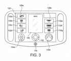
- Figure 3 is a schematic plan view of a handset according to a second embodiment of the present invention.
- the touchscreen display 122 there are two zones 128a, 128b on the touchscreen display 122.
- the display may alternatively be provided with physical icon switches, as described above for the previous embodiment.
- a first zone 128a is associated with vertical movement, and includes a plurality of icons 132a, 132b, 132c, 132d illustrating elements of a surgical operating table to be moved vertically.
- the first zone 128a includes a first physical switch 134a, similar to switch 34a of Figure 1 and 2 , for moving the selected element vertically in an up or down direction of movement, at a speed controlled by pressure applied to the first physical switch 134a which moves the first physical switch 134a away from the central position.
- a second zone 128b is associated with rotational movement and horizontal movement, and includes a plurality of icons 132e, 132f, 132g illustrating elements of a surgical operating table to be moved horizontally (132e) or rotationally (132f, 132g).
- a further icon may be provided in any column to dispose the table in a level position.
- the second zone 128b includes a second physical switch 134b, similar to switch 34c of Figure 1 and 2 , for moving the selected element to a level position, or horizontally or rotationally in a selected one of two opposite directions, at a speed controlled by the degree of angular rotation applied to the second physical switch 134b which moves the second physical switch 134b away from the central position.
- the touchscreen display 122 further includes a central menu region 100, located between the first and second zones 128a, 128b. Beneath the central menu region 100 is physical switch 102, for example a four-direction physical rocker switch 102, for selecting functions from the menu in the central menu region 100.
- This embodiment avoids the cost of a touchscreen for the central menu region, and the first and second zones 128a, 128b may comprise a touchscreen comprising an array of plural individual displayed icons, each of which is associated with a respective switch device located beneath the respective icon.
- a further physical switch 104 as a power ON/OFF button is also provided.
- the ON/OFF switch 104 can be configured to switch ON/OFF the handset 2 and/or the table 4.
- an independent STOP switch (not shown) may be provided which stops all motions of the table 4, and optionally kills the power to the table 4.
Landscapes
- Engineering & Computer Science (AREA)
- Health & Medical Sciences (AREA)
- General Engineering & Computer Science (AREA)
- Theoretical Computer Science (AREA)
- Veterinary Medicine (AREA)
- Public Health (AREA)
- General Health & Medical Sciences (AREA)
- Biomedical Technology (AREA)
- Life Sciences & Earth Sciences (AREA)
- Animal Behavior & Ethology (AREA)
- Physics & Mathematics (AREA)
- General Physics & Mathematics (AREA)
- Human Computer Interaction (AREA)
- Automation & Control Theory (AREA)
- Multimedia (AREA)
- Position Input By Displaying (AREA)
- User Interface Of Digital Computer (AREA)
- Switches With Compound Operations (AREA)
Description
- The present invention relates to a handset for controlling a device having a plurality of movable elements, in particular a surgical operating table.
- Surgical tables, or operating tables, have a variety of different well known configurations, for example comprising a base for standing on a floor, a column extending from the base, and a tabletop providing a patient support surface. There is a general need in the art for surgical tables to have variable height to enable the tabletop to be located at a defined height which is most suitable for the required surgical, therapeutic or diagnostic treatment of a patient positioned on the surgical table. The column is extendable, typically by a telescoping arrangement, to allow the column to be moved between contracted and extended positions in order to lower and/or raise the tabletop to a desired height. In other surgical tables, an arm, instead of a column, can lower and/or raise the tabletop to the desired height.
- Still further, the tabletop of the surgical table is generally required to be movable relative to the column or arm so as to be tiltable about two orthogonal horizontal axes, namely a tilt axis extending longitudinally along the length of the tabletop and a trend axis extending transversely across the length of the tabletop.
- In addition, the tabletop generally includes a number of independently movable segments. For example a head section, one or more torso sections and one or more leg sections.
- It is well known to provide a handset to enable the various movement functions of the surgical operating table to be controlled. The handset may be wirelessly connected to the surgical operating table to be able to send movement commands to the table. Known handsets for controlling surgical operating tables typically comprise many push buttons associated with a variety of icons, and/or text. The icons and text are used to identify the movement available to the respective push button.
- The most-used push buttons tend to be located in an array conveniently positioned for manual control. Examples of the most-used push buttons are: HEAD UP, HEAD DOWN, LEG UP, LEG DOWN, BACK UP, BACK DOWN, SLIDE CRANIALLY, SLIDE CAUDALLY, TREND, REVERSE TREND, AUTO LEVEL. Lesser used functions are typically available on a display screen, often several menu layers down.
- These known handsets suffer from the problem that it can be time consuming and difficult for the healthcare operator to search for and select a push button, from the many push buttons provided, often in a small dimension array, to activate a desired movement of the table. Furthermore, the manual pressing of the selected button to activate the desired movement does not provide any significant visual, audible or touch feedback to the user. In addition, the speed of motion of the selected segment or the table is difficult to control or adjust using the push button. Typically, small adjustments to a selected movement requires the selection of another push button.
- There is a need in the art to provide a handset, in particular a handset for controlling a surgical operating table, which has a more ergonomic design than known handsets, and in particular can more easily and/or more controllably enable movement commands to be readily selected for transmission to the device to be controlled.
-
US 2018 008052 discloses a remote-control device for controlling an appliance having a plurality of appliance components. - The present invention provides a handset for controlling a device having a plurality of movable elements according to claim 1.
- The present invention further provides a surgical operating table in combination with the handset of the present invention.
- The present invention further provides method of controlling a surgical operating table using the handset of the present invention.
- In a preferred embodiment of the present invention, the display is in the form of a screen, and for example may be a touchscreen display wherein the icon switches are touchscreen switches. However, alternatively the icon switches may comprise physical switches.
- In this specification, the term "touchscreen display" is used in a broad sense to mean any device presenting the image of a screen with displayed icons which are touch sensitive. The touchscreen display may comprise a single unitary touchscreen device with displayed icons on a unitary screen and the touchscreen being touch sensitive so that pressing of the touchscreen in the vicinity of the icons activates a signal associated with the icon. Alternatively, the touchscreen display may comprise an array of plural individual displayed icons, each of which is associated with a respective switch device located beneath the respective icon.
- Although the preferred embodiments relate to a handset configured to control a surgical operating table, the handset may be employed, or configured to be employed, to control the movement of any movable or adjustable surface or device.
- The handset of the preferred embodiments provides a number of advantages over known handsets.
- In the preferred embodiments of the present invention, the handset, which is preferably configured to be in the form of a tablet, has a minimum number of icon selector switches, which may be pushed to be selected and may be associated with the icon of a respective pre-defined movement function. The icon switches may be physical switches or may be incorporated into a touchscreen. The icon selector switches are arranged in groups, typically vertical groups. Each group has a physical switch, for example a colour-coded physical switch, associated therewith. The physical switch can be pushed, slid or rotated, and the movement represents the corresponding desired movement of the device to be controlled, such as the surgical operating table. Each group is also associated with a particular movement orientation, typically either vertical, horizontal or rotational. In addition, the orientation of the movement is identified with a corresponding physical shape of the physical switches.
- Accordingly, the handset can employ a minimum number of movement function icon selector switches, which are, for example, touchscreen switches with associated icons. The physical switches can control the direction and speed of movement in a respective movement orientation. For example, an output speed control signal can be generated by moving each respective physical switch away from the central position, and a speed value associated with the output speed control signal increases with increase in distance of the respective physical switch away from the central position. Increased pressure applied to the switch, or increased movement of the switch away from a central position, can act to increase the speed of the selected movement.
- The number of physical switches, for example physical switches which extend above the display surface and are designed for manual operation by pressing, sliding or rotating for example, can also be minimised.
- The icon switches, which may be touchscreen switches with associated icons, can provide haptic and/or visual feedback to the user when selected. Additionally or alternatively, the physical switches can provide haptic and/or visual feedback to the user when selected. In either case, the haptic and/or visual feedback may indicate to the user that the selected function is being executed and/or that a limit of allowed travel or a function stop is imminent or has been reached.
- The display surface, particularly when it is a touchscreen surface, is easy to clean, which is important in a sterile environment of an operating theatre.
- The handset can be safely controlled by a user in a surgical or other medical environment. A desired icon, for example a touchscreen icon, is pressed to select a desired movement of a selected element of the device, or the entire device. The icon is highlighted to confirm its selection. The corresponding physical switch is then moved, for example by pressing, sliding or rotation, with the switch movement corresponding to the desired direction and speed of movement. Release of the physical switch returns the physical switch to a central position and terminates movement.
- The ergonomic design of the preferred embodiments is convenient for left-handed or right-handed use, and can be used in a single-handed operation, particularly when the handset is mounted to or securely supported by a support. The tablet design and shape can enable the handset readily to be placed securely and stably on a surface. In one embodiment, the rear surface of the handset may be provided with a non-slip high friction material e.g. an elastomer, which may form a part of the housing or be attached as a cover.
- Embodiments of the present invention will now be described by way of example only with reference to the accompanying drawings, in which:
-
Figure 1 is a schematic view of a handset according to an embodiment of the present invention in combination with a surgical operating table to be controlled by the handset; -
Figure 2 is a schematic plan view of the handset ofFigure 1 ; and -
Figure 3 is a schematic plan view of a handset according to a second embodiment of the present invention. - Referring to
Figures 1 and 2 , there is shown ahandset 2 according to an embodiment of the present invention. Thehandset 2 is configured for controlling a device having a plurality of movable elements or parts, in particular a surgical operating table 4. - Any suitable surgical operating table configuration may be utilized in conjunction with the
handset 2 of the present invention, provided that the function of the surgical operating table 4 correlates with the functional control provided by thehandset 2. In one example as shown inFigure 1 , the surgical operating table 4 has movable elements which comprise segments of atabletop 6 of the surgical operating table 4. In this example, these segments comprise a head section 8, anupper body section 10, alower body section 12 and one or twoleg sections 14. The movable elements also comprise acolumn 16 on which thetabletop 6 is mounted; however, other surgical tables incorporate an arm instead of a column for raising and lowering the tabletop. - A mechanism, generally indicated by
reference numeral 18, is provided in the surgical operating table 4 which can be controlled to incline thetabletop 6 in a Trendelenburg position, in which the head section 8 is lowered relative to the other sections of thetabletop 6, and in a Reverse Trendelenburg position, in which the head section 8 is raised relative to the other sections of thetabletop 6, by rotating thetabletop 6 about a transverse trend axis extending across thetabletop 6. Themechanism 18 also can be controlled to tilt thetabletop 6 by rotating thetabletop 6 about a longitudinal tilt axis extending along thetabletop 6. - Drive mechanisms are provided within the surgical operating table 4 to move the
tabletop 6 to a desired position or configuration according to a command from thehandset 2. Typically, thehandset 2 is adapted to control the surgical operating table 4 by wireless communication. Alternatively, thehandset 2 is adapted to control the surgical operating table 4 by a wired connection. Thehandset 2 is adapted translationally and/or rotationally to move individual segments of thetabletop 6 or theentire tabletop 6. - Thus, individual segments of the
tabletop 6 or theentire tabletop 6 can be translationally moved in a vertical orientation, i.e. in an upward direction or a downward direction; theentire tabletop 6 can be translationally moved in a horizontal orientation, i.e. in a direction extending from the head section 8 to the one or twoleg sections 14 or in an opposite direction; and/or theentire tabletop 6 can be rotationally moved about the transverse trend axis and/or the longitudinal tilt axis. - The
handset 2 comprises ahousing 20. Atouchscreen display 22 is located on afront face 24 of thehousing 20. - The
housing 2 andtouchscreen display 22 have the shape and configuration of a tablet. The housing may be provided with one ormore handles 26 and is typically ergonomically configured to provide right-handed or left-handed manual operation by a user. Typically, twohandles 26 are provided on opposite sides of thehandset 2. A strap may be fitted to thehandles 26 for fitting thehandset 2 around the arm of a user or suspending thehandset 2 around the neck of a user. - The
touchscreen display 22 is divided into a plurality of zones 28. Each zone 28 includes at least one icon switch in the form of atouchscreen switch 30. Eachtouchscreen switch 30 is aligned with a respective associated icon 32. Each icon 32 identifies a respective element or group of elements of the device to be controlled by the respective touchscreen switch, in the illustrated embodiment the device being the surgical operating table 4. - As described above, in the illustrated embodiment the display is a
touchscreen display 22; however, a display having physical icon switches 30 can alternatively be utilized in accordance with the present invention. - The
handset 2 further comprises a plurality of physical switches 34 on thefront face 24. Each physical switch 34 is associated with a respective zone 28. Each physical switch 34 is configured to control movement of the element or elements shown by the icon or icons 32 in the respective zone 28. - The
handset 2 further comprises acontrol mechanism 35 within thehousing 20 which is connected to the plurality of touchscreen switches 30 and the plurality of physical switches 34. Thecontrol mechanism 35 is arranged to generate an output control signal for transmission to the device, in the illustrated embodiment the device being the surgical operating table 4, in response to an input command at the plurality of touchscreen switches 30 and the plurality of physical switches 34. - Referring in particular to the arrangement of the zones 28, touchscreen switches 30 and physical switches 34 on the
front face 24 of thehousing 20, in the illustrated embodiment the plurality of zones 28 are serially arranged on thetouchscreen display 22. Typically, the plurality ofzones columns touchscreen display 22. - By providing a series of
columns respective zone touchscreen display 22 is ergonomically suitable for use by right-handed or left-handed users, as compared to an arrangement of rows arranged down thetouchscreen display 22. - The
touchscreen display 22 is adapted to highlight a respective associated icon 32 when thetouchscreen switch 30 is manually pressed. For example, thetouchscreen display 22 may be adapted to illuminate, or increase an illumination level of, a respective associated icon 32 when thetouchscreen switch 30 is manually pressed. In the illustrated embodiment, the icons 32 are visible only when thetouchscreen display 22 is electrically powered and is switched on. In an alternative embodiment, the icons 32 are visible when thetouchscreen display 22 is not electrically powered and is switched off. - The plurality of physical switches 34 are correspondingly serially arranged on the
touchscreen display 22. The plurality of physical switches 34 form a row 40 transversely extending across thetouchscreen display 22. In the illustrated embodiment, eachphysical switch respective column - Each
physical switch touchscreen display 22. - Each
physical switch respective zone physical switch respective zone peripheral edge physical switch - For example, a translational motion in opposite directions along a common orientation for the element or elements of the table 4 is associated with an elongate physical shape, and
peripheral edge physical switch peripheral edge 36b, of thephysical switch 34b. Eachphysical switch physical indicator front surface 44 thereof. Thephysical indicator respective zone - In the illustrated embodiment, the
physical indicator front surface 44 of the respectivephysical switch physical indicator front surface 44 of the respectivephysical switch - In the illustrated embodiment, each
physical indicator physical switch physical indicator - Each
physical switch physical switch control mechanism 35 is arranged so that an output speed control signal is generated by moving each respectivephysical switch physical switch - In the plurality of physical switches, a first
physical switch 34a is configured to control movement of the element or elements along a first translational orientation and a secondphysical switch 34c is configured to control movement of the element or elements along a second translational orientation which is inclined to the first translational orientation. - In the illustrated embodiment, the first and second translational orientations are mutually orthogonal; the first translational orientation is associated with vertical motion of the element or elements and the second translational orientation is associated with horizontal motion of the element or elements.
- Each of the first and second
physical switches respective end - The first
physical switch 34a is associated with vertical motion of the element or elements and theperipheral edge 36a of the firstphysical switch 34a is oriented along a direction extending between opposite upper andlower edges touchscreen display 22. Typically, theperipheral edge 36a of the firstphysical switch 34a is elliptical and a long axis of the elliptical shape is oriented along the direction extending between the opposite upper andlower edges touchscreen display 22. - In the illustrated embodiment, the first
physical switch 34a is a single rocker switch or slider switch. A thumb or finger can be placed at the centre of the firstphysical switch 34a and then rocked or slid in a desired direction to activate the switch in a desired direction, i.e. up or down, by pressing down on the selectedend switch 34a to cause sliding. - Alternatively, a selected
end physical switch 34a can be pushed down by the finger or thumb to activate the switch in a desired direction. - In an alternative embodiment, the first
physical switch 34a may comprise a pair of individual switches which are closely adjacent to each other in a vertical direction and are activated using similar rocking or pressing motions as described above for the single rocker switch. - In the illustrated embodiment, the
first zone 28a includes four icons 32. Operation of the icons 32, touchscreen switches 30 and the firstphysical switch 34a associated with thefirst zone 28a controls vertical motion of the surgical operating table. Thetop icon 32a in thecolumn 38a functions to level thetabletop 6; the nextlower icon 32b in thecolumn 38a functions to raise or lower the height of thetabletop 6; the nextlower icon 32c in thecolumn 38a functions to raise or lower the leg section(s) 14 of thetabletop 6; and the nextlower icon 32d in thecolumn 38a functions to raise or lower the head section 8 of thetabletop 6. - The second
physical switch 34c is associated with horizontal motion of the element or elements and theperipheral edge 36c of the secondphysical switch 34c is oriented along a direction extending between opposite left-hand and right-hand sides touchscreen display 22. Typically, theperipheral edge 36c of the secondphysical switch 34c is elliptical and a longitudinal axis of the elliptical shape is oriented along the direction extending between the opposite left-hand and right-hand sides touchscreen display 22. - In the illustrated embodiment, as described above for the first
physical switch 34a, the secondphysical switch 34c is a single rocker switch or slider switch. A thumb or finger can be placed at the centre of the secondphysical switch 34c and then rocked or slid in a desired direction to activate the switch in a desired direction, i.e. left or right, by pressing down on the selectedend switch 34a to cause sliding. - Alternatively, a selected
end physical switch 34c can be pushed down by the finger or thumb to activate the switch in a desired direction. In an alternative embodiment, the secondphysical switch 34c may comprise a pair of individual switches which are closely adjacent to each other in a horizontal direction and are activated using similar rocking or pressing motions as described above for the single rocker switch. - In the illustrated embodiment, the
second zone 28c includes oneicon 32e incolumn 38c. Operation of theicon 32e,touchscreen switch 30 and the secondphysical switch 34c associated with thesecond zone 28c controls horizontal motion of the surgical operating table. Theicon 32e in thecolumn 38c functions to slide the tabletop either cranially or caudally. - A third
physical switch 34b is configured to control movement in a rotational orientation. The thirdphysical switch 34b is associated with rotational motion of the element or elements. The thirdphysical switch 34b is rotatable in opposite rotational directions and is adapted to control movement of the element or elements in a selected one of corresponding opposite directions when the thirdphysical switch 34b is manually rotated in a respective selected direction of the opposite rotational directions. Typically, theperipheral edge 36b of the thirdphysical switch 34b is a surface of rotation, which may be circular, although other configurations, such as a regular polygon, for example an octagon, may be used. - In the illustrated embodiment, the third
physical switch 34b is a single rotary knob, but any other rotary control may be used. - In the illustrated embodiment, the
third zone 28b includes two icons 32. Operation of the icons 32, touchscreen switches 30 and the thirdphysical switch 34b associated with thethird zone 28b controls rotational motion of the surgical operating table. Thetop icon 32f in thecolumn 38b functions to rotate thetabletop 6 in trend or reverse trend; and thebottom icon 32g in thecolumn 38b functions to rotate the tabletop by tilting left or right relative to the longitudinal axis of the tabletop 8. - In the illustrated embodiment, the
touchscreen display 22 may also include amenu section 154, which may be used to set up the device and from which other movements or functions of the surgical operating table 2 may be controlled. Anauxiliary area 156 on thetouchscreen display 22 may control other functions or components of the surgical operating table 2. - A physical power ON/
OFF switch 62 is located on thehousing 20. The ON/OFF switch 62 can be configured to switch ON/OFF thehandset 2 and/or the table 4. - In an alternative arrangement, an independent STOP switch (not shown) may be provided which stops all motions of the table 4, and optionally kills the power to the table 4.
- In operation, when it is desired to move the tabletop 8 or a segment of the tabletop 8, a user manually presses on the required icon 32 to select the desired movement function. Pressing the icon 32 causes the associated
touchscreen switch 30 to be switched on. The icon 32 is then highlighted or illuminated to provide a visual indication that the icon 32 has been selected. - The selected movement function associated with the selected icon 32 is then controlled by moving the associated physical switch 34 which is in the same zone 28 as the selected icon 32. The physical switch 34 can be operated by pressing a selected one of two ends or moving in a selected one of two opposite directions.
- This permits a desired movement direction along the selected orientation, vertical, horizontal, or rotation, to be readily selected, and optionally controlled in a back-and-forth adjustment by alternately moving the two ends of the physical switch 34 or rotating the physical switch 34 in opposite directions.
- Increased pressure on the ends or increased rotation to cause increased motion of the physical switch 34 from the central position causes increased speed of motion of the controlled tabletop 8 or segment of the tabletop 8.
- Operation of the physical switch 34 causes the
control mechanism 35 to generate an output control signal for transmission to the device in response to an input command at the plurality of touchscreen switches 30 and the plurality of physical switches 34. - After a preset cut-out period, the selected icon 32 is automatically deselected by the
control mechanism 35. -
Figure 3 is a schematic plan view of a handset according to a second embodiment of the present invention. - In this embodiment, there are two
zones touchscreen display 122. Again, although atouchscreen display 122 is illustrated, the display may alternatively be provided with physical icon switches, as described above for the previous embodiment. - A
first zone 128a is associated with vertical movement, and includes a plurality oficons first zone 128a includes a firstphysical switch 134a, similar to switch 34a ofFigure 1 and 2 , for moving the selected element vertically in an up or down direction of movement, at a speed controlled by pressure applied to the firstphysical switch 134a which moves the firstphysical switch 134a away from the central position. - A
second zone 128b is associated with rotational movement and horizontal movement, and includes a plurality oficons second zone 128b includes a secondphysical switch 134b, similar to switch 34c ofFigure 1 and 2 , for moving the selected element to a level position, or horizontally or rotationally in a selected one of two opposite directions, at a speed controlled by the degree of angular rotation applied to the secondphysical switch 134b which moves the secondphysical switch 134b away from the central position. - The
touchscreen display 122 further includes acentral menu region 100, located between the first andsecond zones central menu region 100 isphysical switch 102, for example a four-directionphysical rocker switch 102, for selecting functions from the menu in thecentral menu region 100. This embodiment avoids the cost of a touchscreen for the central menu region, and the first andsecond zones - A further
physical switch 104 as a power ON/OFF button is also provided. The ON/OFF switch 104 can be configured to switch ON/OFF thehandset 2 and/or the table 4. - In an alternative arrangement, an independent STOP switch (not shown) may be provided which stops all motions of the table 4, and optionally kills the power to the table 4.
- Various modifications can be made to the above-described embodiments without departing from the scope of the present invention, which is defined by the claims.
Claims (14)
- A handset for controlling a device having a plurality of movable elements, optionally wherein the device is a surgical operating table and the elements comprise segments of a tabletop of the surgical operating table, the handset comprising:a housing (20);a display (22) on a front face of the housing, the display being divided into a plurality of zones, each zone including at least one icon switch, each icon switch being aligned with a respective associated icon, wherein each icon identifies a respective element or group of elements of a device to be controlled by the respective icon switch, wherein the plurality of zones are serially arranged on the display to form a series of columns of icon switches arranged on the display, each zone comprising a respective column and at least one of the columns comprising a plurality of icon switches,a plurality of physical switches (34) on the front face, each physical switch being associated with a respective zone, and wherein each physical switch is configured to control movement of the element or elements shown by the icon or icons in the respective zone, the plurality of physical switches including:a first physical switch (34a) configured to control movement of the element or elements shown by the icon or icons in the respective zone along a first translational orientation associated with vertical motion of the element or elements of the device;a second physical switch (34c) configured to control movement of the element or elements shown by the icon or icons in the respective zone along a second translational orientation which is orthogonal to the first translational orientation and is associated with horizontal motion of the element or elements of the device; anda third physical switch (34b) configured to control movement of the element or elements shown by the icon or icons in the respective zone in a rotational orientation, anda control mechanism (35) within the housing which is connected to the plurality of icon switches and the plurality of physical switches, the control mechanism being arranged to generate an output control signal for transmission to the device in response to an input command at the plurality of icon switches and the plurality of physical switches.
- A handset according to claim 1 wherein each physical switch (34) is configured to control movement of the element or elements in opposite directions along a common orientation of the element or elements shown by the icon or icons in the respective zone.
- A handset according to any foregoing claim wherein each of the first (34a) and second (34b) physical switches has a respective pair of opposite ends and is adapted to control movement of the element or elements in a selected one of corresponding opposite directions when the respective end is manually pushed.
- A handset according to any foregoing claim wherein: i) the third physical switch is rotatable in opposite rotational directions and is adapted to control movement of the element or elements in a selected one of corresponding opposite directions when the third physical switch is manually rotated in a respective selected direction of the opposite rotational directions; and/or ii) each physical switch and/or physical indicator has a respective individual colour and the colours of the physical switch and/or physical indicators are mutually different.
- A handset according to any foregoing claim wherein each physical switch (34) has a physical shape associated with a respective orientation of movement of the element or elements shown by the icon or icons in the respective zone.
- A handset according to any foregoing claim wherein: i) the display is adapted to highlight a respective associated icon when the touchscreen switch is manually pressed, optionally wherein the display is adapted to illuminate, or increase an illumination level of, a respective associated icon when the icon switch is manually pressed; further optionally wherein each physical switch is located at a lower end of a respective column; and/or ii) the plurality of physical switches are serially arranged on the display, optionally wherein the plurality of physical switches form a row transversely extending across the display.
- A handset according to any foregoing claim wherein each physical switch (34) is movable in opposite directions about a central position, and optionally is a rocker switch, a slider switch or a rotatable switch.
- A handset according to claim 7 wherein: i) each physical switch is biased towards the central position; and/or ii) the control mechanism is arranged so that an output speed control signal is generated by moving each respective physical switch away from the central position, optionally wherein a speed value associated with the output speed control signal increases with increase in distance of the respective physical switch away from the central position.
- A surgical operating table in combination with a handset according to any foregoing claim.
- A method of controlling a surgical operating table according to claim 9, the method comprising the steps of:i. pressing on an icon of the display (22), thereby to operate an icon switch associated therewith, to select a desired movement function of a tabletop of the surgical operating table, or a segment of the tabletop;ii. moving a physical switch (34) which is in the same zone as the selected icon; andiii. in response to the pressing of the selected icon and moving of the physical switch, the control mechanism (35) generating an output control signal for transmission to the surgical operating table in response to an input command at the icon switch and the physical switch.
- A method according to claim 10 wherein: i) the step of pressing the icon causes an associated icon switch to be switched on; and/or ii) the step of pressing the icon causes the icon to be highlighted or illuminated to provide a visual indication that the icon has been selected.
- A method according to claim 10 or claim 11 wherein in the step of moving the physical switch, the physical switch is operated by pressing a selected one of two ends of the physical switch, or by moving the physical switch in a selected one of two opposite directions.
- A method according to claim 12 wherein: i) the step of pressing a selected one of two ends of the physical switch comprises rocking the physical switch about a central position; and/or ii) in the pressing step, increased pressure on the ends, or increased rocking movement for the central position, correspondingly causes increased speed of motion of the controlled tabletop or segment of the tabletop; and/or iii) the step of moving the physical switch in a selected one of two opposite directions comprises rotating the physical switch about a central position, optionally wherein increased rotation of the physical switch from the central position correspondingly causes increased speed of motion of the controlled tabletop or segment of the tabletop; and/or iv) the step of moving the physical switch in a selected one of two opposite directions comprises sliding the physical switch away from a central position, optionally wherein increased sliding of the physical switch from the central position correspondingly causes increased speed of motion of the controlled tabletop or segment of the tabletop.
- A method according to any one of claims 10 to 13 wherein: i) in the step of moving the physical switch, the physical switch is moved in a selected movement direction which corresponds to a desired movement direction of the tabletop of the surgical operating table, or the segment of the tabletop, optionally wherein the desired movement direction is along a selected vertical, horizontal, or rotational orientation, further optionally wherein the zone and the physical switch therein are associated with respective selected vertical, horizontal, or rotational orientation for the motion of the tabletop of the surgical operating table, or the segment of the tabletop; and/or ii) after a preset cut-out period following step i, the selected icon is automatically deselected by the control mechanism.
Applications Claiming Priority (2)
| Application Number | Priority Date | Filing Date | Title |
|---|---|---|---|
| GB1805647.3A GB2572613B (en) | 2018-04-05 | 2018-04-05 | Handset |
| PCT/EP2019/058412 WO2019193058A1 (en) | 2018-04-05 | 2019-04-03 | Handset |
Publications (2)
| Publication Number | Publication Date |
|---|---|
| EP3768212A1 EP3768212A1 (en) | 2021-01-27 |
| EP3768212B1 true EP3768212B1 (en) | 2025-02-19 |
Family
ID=62202994
Family Applications (1)
| Application Number | Title | Priority Date | Filing Date |
|---|---|---|---|
| EP19716130.0A Active EP3768212B1 (en) | 2018-04-05 | 2019-04-03 | Handset |
Country Status (5)
| Country | Link |
|---|---|
| US (1) | US11877961B2 (en) |
| EP (1) | EP3768212B1 (en) |
| CA (1) | CA3095522A1 (en) |
| GB (1) | GB2572613B (en) |
| WO (1) | WO2019193058A1 (en) |
Families Citing this family (2)
| Publication number | Priority date | Publication date | Assignee | Title |
|---|---|---|---|---|
| JP7131110B2 (en) * | 2018-06-18 | 2022-09-06 | 富士フイルムビジネスイノベーション株式会社 | Display control device, image forming device, and program |
| USD1062780S1 (en) * | 2023-03-07 | 2025-02-18 | Mitsubishi Electric Corporation | Display screen or portion thereof with graphical user interface |
Family Cites Families (13)
| Publication number | Priority date | Publication date | Assignee | Title |
|---|---|---|---|---|
| US5926002A (en) * | 1995-02-21 | 1999-07-20 | Getinge/Castle, Inc. | Pendent with safety features for patient handling apparatus |
| FR2819173B1 (en) * | 2001-01-09 | 2003-04-11 | Alm | MULTI-SECTIONS MOTORIZED OPERATING TABLE |
| US20030115672A1 (en) | 2001-12-21 | 2003-06-26 | Newkirk David C. | Dual patient support control system |
| CN2560334Y (en) * | 2002-02-22 | 2003-07-16 | 洪盛隆 | Operating table controller |
| EP1647213B2 (en) * | 2004-10-12 | 2022-08-10 | Wissner-Bosserhoff GmbH | Bed with a manual switch |
| DE102005054223A1 (en) * | 2005-11-14 | 2007-05-16 | Maquet Gmbh & Co Kg | Device for adjusting an operating table |
| FR2938427B1 (en) | 2008-11-19 | 2010-12-10 | Steris Surgical Technologies | DEVICE FOR CONTROLLING AN OPERATING TABLE |
| US20120194436A1 (en) * | 2011-01-28 | 2012-08-02 | Mahesh Kumar Thodupunuri | Handheld bed controller pendant with liquid crystal display |
| WO2013071246A1 (en) * | 2011-11-11 | 2013-05-16 | Hill-Rom Services, Inc. | Person support apparatus |
| FI124482B (en) * | 2012-10-05 | 2014-09-15 | Merivaara Oy | Procedure for operating the operating table with a control pedal |
| US20140250597A1 (en) * | 2013-03-11 | 2014-09-11 | Select Comfort Corporation | Adjustable bed foundation system with built-in self-test |
| DE102015102351B4 (en) * | 2015-02-19 | 2018-08-30 | MAQUET GmbH | Remote control device for controlling a medical device, system with a remote control device and a medical device and control method |
| GB2572614B (en) * | 2018-04-05 | 2021-12-08 | Steris Solutions Ltd | Handset for controlling a support device or a movable surface |
-
2018
- 2018-04-05 GB GB1805647.3A patent/GB2572613B/en active Active
-
2019
- 2019-04-03 CA CA3095522A patent/CA3095522A1/en active Pending
- 2019-04-03 WO PCT/EP2019/058412 patent/WO2019193058A1/en not_active Ceased
- 2019-04-03 EP EP19716130.0A patent/EP3768212B1/en active Active
- 2019-04-03 US US17/044,410 patent/US11877961B2/en active Active
Also Published As
| Publication number | Publication date |
|---|---|
| GB2572613A (en) | 2019-10-09 |
| EP3768212A1 (en) | 2021-01-27 |
| WO2019193058A1 (en) | 2019-10-10 |
| CA3095522A1 (en) | 2019-10-10 |
| US11877961B2 (en) | 2024-01-23 |
| GB2572613B (en) | 2021-09-29 |
| GB201805647D0 (en) | 2018-05-23 |
| US20210106483A1 (en) | 2021-04-15 |
Similar Documents
| Publication | Publication Date | Title |
|---|---|---|
| US11709592B2 (en) | Handset for controlling a support device or a movable surface | |
| EP1028684B1 (en) | Medical equipment controller | |
| RU2345750C2 (en) | Device for regulation of operation table support surface | |
| ES2645237T3 (en) | Operation device for a household appliance with an electronic display panel | |
| US11877961B2 (en) | Handset having a display of zones and icon switches for controlling movement associated elements of a device such as a surgical operating table | |
| US8266743B2 (en) | Examination table with motion tracking | |
| WO2017060383A1 (en) | Method and device for controlling movement of a motorized c-arm | |
| CN108633336A (en) | Light Console with Dual-Axis Encoder | |
| JP2013511317A (en) | Patient support motion control device | |
| JPH06197932A (en) | Controlling apparatus for medical treatment device for human or animal | |
| EP3464781B1 (en) | Control center for an aerial device with control lever | |
| JP5089931B2 (en) | Medical image display device | |
| EP1586970A1 (en) | User interface device | |
| JP6161336B2 (en) | Dental treatment system | |
| EP3768211B1 (en) | Handset for controlling a surgical operating table | |
| JP4963900B2 (en) | X-ray equipment | |
| JP4206748B2 (en) | Dental chair unit tray table | |
| JPH09322919A (en) | Medical and dental treatment system | |
| JP2004147983A (en) | X-ray CT system | |
| EP2716273B1 (en) | Method for controlling an operating table with a foot-operated controller | |
| EP2762998A1 (en) | PC with integrated motion sensor |
Legal Events
| Date | Code | Title | Description |
|---|---|---|---|
| STAA | Information on the status of an ep patent application or granted ep patent |
Free format text: STATUS: UNKNOWN |
|
| STAA | Information on the status of an ep patent application or granted ep patent |
Free format text: STATUS: THE INTERNATIONAL PUBLICATION HAS BEEN MADE |
|
| PUAI | Public reference made under article 153(3) epc to a published international application that has entered the european phase |
Free format text: ORIGINAL CODE: 0009012 |
|
| STAA | Information on the status of an ep patent application or granted ep patent |
Free format text: STATUS: REQUEST FOR EXAMINATION WAS MADE |
|
| 17P | Request for examination filed |
Effective date: 20201021 |
|
| AK | Designated contracting states |
Kind code of ref document: A1 Designated state(s): AL AT BE BG CH CY CZ DE DK EE ES FI FR GB GR HR HU IE IS IT LI LT LU LV MC MK MT NL NO PL PT RO RS SE SI SK SM TR |
|
| AX | Request for extension of the european patent |
Extension state: BA ME |
|
| RAP1 | Party data changed (applicant data changed or rights of an application transferred) |
Owner name: STERIS SOLUTIONS LIMITED |
|
| DAV | Request for validation of the european patent (deleted) | ||
| DAX | Request for extension of the european patent (deleted) | ||
| P01 | Opt-out of the competence of the unified patent court (upc) registered |
Effective date: 20230513 |
|
| STAA | Information on the status of an ep patent application or granted ep patent |
Free format text: STATUS: EXAMINATION IS IN PROGRESS |
|
| 17Q | First examination report despatched |
Effective date: 20240605 |
|
| GRAP | Despatch of communication of intention to grant a patent |
Free format text: ORIGINAL CODE: EPIDOSNIGR1 |
|
| STAA | Information on the status of an ep patent application or granted ep patent |
Free format text: STATUS: GRANT OF PATENT IS INTENDED |
|
| INTG | Intention to grant announced |
Effective date: 20241108 |
|
| GRAS | Grant fee paid |
Free format text: ORIGINAL CODE: EPIDOSNIGR3 |
|
| GRAA | (expected) grant |
Free format text: ORIGINAL CODE: 0009210 |
|
| STAA | Information on the status of an ep patent application or granted ep patent |
Free format text: STATUS: THE PATENT HAS BEEN GRANTED |
|
| AK | Designated contracting states |
Kind code of ref document: B1 Designated state(s): AL AT BE BG CH CY CZ DE DK EE ES FI FR GB GR HR HU IE IS IT LI LT LU LV MC MK MT NL NO PL PT RO RS SE SI SK SM TR |
|
| REG | Reference to a national code |
Ref country code: GB Ref legal event code: FG4D |
|
| REG | Reference to a national code |
Ref country code: CH Ref legal event code: EP |
|
| REG | Reference to a national code |
Ref country code: IE Ref legal event code: FG4D |
|
| REG | Reference to a national code |
Ref country code: DE Ref legal event code: R096 Ref document number: 602019066122 Country of ref document: DE |
|
| REG | Reference to a national code |
Ref country code: NL Ref legal event code: MP Effective date: 20250219 |
|
| PG25 | Lapsed in a contracting state [announced via postgrant information from national office to epo] |
Ref country code: RS Free format text: LAPSE BECAUSE OF FAILURE TO SUBMIT A TRANSLATION OF THE DESCRIPTION OR TO PAY THE FEE WITHIN THE PRESCRIBED TIME-LIMIT Effective date: 20250519 |
|
| PG25 | Lapsed in a contracting state [announced via postgrant information from national office to epo] |
Ref country code: FI Free format text: LAPSE BECAUSE OF FAILURE TO SUBMIT A TRANSLATION OF THE DESCRIPTION OR TO PAY THE FEE WITHIN THE PRESCRIBED TIME-LIMIT Effective date: 20250219 |
|
| PG25 | Lapsed in a contracting state [announced via postgrant information from national office to epo] |
Ref country code: PL Free format text: LAPSE BECAUSE OF FAILURE TO SUBMIT A TRANSLATION OF THE DESCRIPTION OR TO PAY THE FEE WITHIN THE PRESCRIBED TIME-LIMIT Effective date: 20250219 |
|
| PGFP | Annual fee paid to national office [announced via postgrant information from national office to epo] |
Ref country code: DE Payment date: 20250429 Year of fee payment: 7 |
|
| PG25 | Lapsed in a contracting state [announced via postgrant information from national office to epo] |
Ref country code: ES Free format text: LAPSE BECAUSE OF FAILURE TO SUBMIT A TRANSLATION OF THE DESCRIPTION OR TO PAY THE FEE WITHIN THE PRESCRIBED TIME-LIMIT Effective date: 20250219 |
|
| REG | Reference to a national code |
Ref country code: LT Ref legal event code: MG9D |
|
| PG25 | Lapsed in a contracting state [announced via postgrant information from national office to epo] |
Ref country code: NO Free format text: LAPSE BECAUSE OF FAILURE TO SUBMIT A TRANSLATION OF THE DESCRIPTION OR TO PAY THE FEE WITHIN THE PRESCRIBED TIME-LIMIT Effective date: 20250519 Ref country code: IS Free format text: LAPSE BECAUSE OF FAILURE TO SUBMIT A TRANSLATION OF THE DESCRIPTION OR TO PAY THE FEE WITHIN THE PRESCRIBED TIME-LIMIT Effective date: 20250619 |
|
| PG25 | Lapsed in a contracting state [announced via postgrant information from national office to epo] |
Ref country code: NL Free format text: LAPSE BECAUSE OF FAILURE TO SUBMIT A TRANSLATION OF THE DESCRIPTION OR TO PAY THE FEE WITHIN THE PRESCRIBED TIME-LIMIT Effective date: 20250219 |
|
| PG25 | Lapsed in a contracting state [announced via postgrant information from national office to epo] |
Ref country code: HR Free format text: LAPSE BECAUSE OF FAILURE TO SUBMIT A TRANSLATION OF THE DESCRIPTION OR TO PAY THE FEE WITHIN THE PRESCRIBED TIME-LIMIT Effective date: 20250219 |
|
| PG25 | Lapsed in a contracting state [announced via postgrant information from national office to epo] |
Ref country code: PT Free format text: LAPSE BECAUSE OF FAILURE TO SUBMIT A TRANSLATION OF THE DESCRIPTION OR TO PAY THE FEE WITHIN THE PRESCRIBED TIME-LIMIT Effective date: 20250620 Ref country code: LV Free format text: LAPSE BECAUSE OF FAILURE TO SUBMIT A TRANSLATION OF THE DESCRIPTION OR TO PAY THE FEE WITHIN THE PRESCRIBED TIME-LIMIT Effective date: 20250219 |
|
| PGFP | Annual fee paid to national office [announced via postgrant information from national office to epo] |
Ref country code: FR Payment date: 20250425 Year of fee payment: 7 |
|
| PG25 | Lapsed in a contracting state [announced via postgrant information from national office to epo] |
Ref country code: BG Free format text: LAPSE BECAUSE OF FAILURE TO SUBMIT A TRANSLATION OF THE DESCRIPTION OR TO PAY THE FEE WITHIN THE PRESCRIBED TIME-LIMIT Effective date: 20250219 Ref country code: GR Free format text: LAPSE BECAUSE OF FAILURE TO SUBMIT A TRANSLATION OF THE DESCRIPTION OR TO PAY THE FEE WITHIN THE PRESCRIBED TIME-LIMIT Effective date: 20250520 |
|
| REG | Reference to a national code |
Ref country code: AT Ref legal event code: MK05 Ref document number: 1767625 Country of ref document: AT Kind code of ref document: T Effective date: 20250219 |
|
| PG25 | Lapsed in a contracting state [announced via postgrant information from national office to epo] |
Ref country code: SE Free format text: LAPSE BECAUSE OF FAILURE TO SUBMIT A TRANSLATION OF THE DESCRIPTION OR TO PAY THE FEE WITHIN THE PRESCRIBED TIME-LIMIT Effective date: 20250219 |
|
| PG25 | Lapsed in a contracting state [announced via postgrant information from national office to epo] |
Ref country code: SM Free format text: LAPSE BECAUSE OF FAILURE TO SUBMIT A TRANSLATION OF THE DESCRIPTION OR TO PAY THE FEE WITHIN THE PRESCRIBED TIME-LIMIT Effective date: 20250219 |
|
| PG25 | Lapsed in a contracting state [announced via postgrant information from national office to epo] |
Ref country code: DK Free format text: LAPSE BECAUSE OF FAILURE TO SUBMIT A TRANSLATION OF THE DESCRIPTION OR TO PAY THE FEE WITHIN THE PRESCRIBED TIME-LIMIT Effective date: 20250219 |
|
| PG25 | Lapsed in a contracting state [announced via postgrant information from national office to epo] |
Ref country code: IT Free format text: LAPSE BECAUSE OF FAILURE TO SUBMIT A TRANSLATION OF THE DESCRIPTION OR TO PAY THE FEE WITHIN THE PRESCRIBED TIME-LIMIT Effective date: 20250219 |
|
| PG25 | Lapsed in a contracting state [announced via postgrant information from national office to epo] |
Ref country code: AT Free format text: LAPSE BECAUSE OF FAILURE TO SUBMIT A TRANSLATION OF THE DESCRIPTION OR TO PAY THE FEE WITHIN THE PRESCRIBED TIME-LIMIT Effective date: 20250219 |
|
| PG25 | Lapsed in a contracting state [announced via postgrant information from national office to epo] |
Ref country code: CZ Free format text: LAPSE BECAUSE OF FAILURE TO SUBMIT A TRANSLATION OF THE DESCRIPTION OR TO PAY THE FEE WITHIN THE PRESCRIBED TIME-LIMIT Effective date: 20250219 Ref country code: EE Free format text: LAPSE BECAUSE OF FAILURE TO SUBMIT A TRANSLATION OF THE DESCRIPTION OR TO PAY THE FEE WITHIN THE PRESCRIBED TIME-LIMIT Effective date: 20250219 |
|
| PG25 | Lapsed in a contracting state [announced via postgrant information from national office to epo] |
Ref country code: RO Free format text: LAPSE BECAUSE OF FAILURE TO SUBMIT A TRANSLATION OF THE DESCRIPTION OR TO PAY THE FEE WITHIN THE PRESCRIBED TIME-LIMIT Effective date: 20250219 |
|
| PG25 | Lapsed in a contracting state [announced via postgrant information from national office to epo] |
Ref country code: SK Free format text: LAPSE BECAUSE OF FAILURE TO SUBMIT A TRANSLATION OF THE DESCRIPTION OR TO PAY THE FEE WITHIN THE PRESCRIBED TIME-LIMIT Effective date: 20250219 |
|
| REG | Reference to a national code |
Ref country code: DE Ref legal event code: R097 Ref document number: 602019066122 Country of ref document: DE |
|
| REG | Reference to a national code |
Ref country code: CH Ref legal event code: H13 Free format text: ST27 STATUS EVENT CODE: U-0-0-H10-H13 (AS PROVIDED BY THE NATIONAL OFFICE) Effective date: 20251125 |
|
| PG25 | Lapsed in a contracting state [announced via postgrant information from national office to epo] |
Ref country code: LU Free format text: LAPSE BECAUSE OF NON-PAYMENT OF DUE FEES Effective date: 20250403 |
|
| PG25 | Lapsed in a contracting state [announced via postgrant information from national office to epo] |
Ref country code: MC Free format text: LAPSE BECAUSE OF FAILURE TO SUBMIT A TRANSLATION OF THE DESCRIPTION OR TO PAY THE FEE WITHIN THE PRESCRIBED TIME-LIMIT Effective date: 20250219 |
|
| PLBE | No opposition filed within time limit |
Free format text: ORIGINAL CODE: 0009261 |
|
| STAA | Information on the status of an ep patent application or granted ep patent |
Free format text: STATUS: NO OPPOSITION FILED WITHIN TIME LIMIT |
|
| REG | Reference to a national code |
Ref country code: BE Ref legal event code: MM Effective date: 20250430 |
|
| PG25 | Lapsed in a contracting state [announced via postgrant information from national office to epo] |
Ref country code: BE Free format text: LAPSE BECAUSE OF NON-PAYMENT OF DUE FEES Effective date: 20250430 |
|
| PG25 | Lapsed in a contracting state [announced via postgrant information from national office to epo] |
Ref country code: CH Free format text: LAPSE BECAUSE OF NON-PAYMENT OF DUE FEES Effective date: 20250430 |
|
| 26N | No opposition filed |
Effective date: 20251120 |
|
| GBPC | Gb: european patent ceased through non-payment of renewal fee |
Effective date: 20250519 |
|
| PG25 | Lapsed in a contracting state [announced via postgrant information from national office to epo] |
Ref country code: GB Free format text: LAPSE BECAUSE OF NON-PAYMENT OF DUE FEES Effective date: 20250519 |
|
| PG25 | Lapsed in a contracting state [announced via postgrant information from national office to epo] |
Ref country code: IE Free format text: LAPSE BECAUSE OF NON-PAYMENT OF DUE FEES Effective date: 20250403 |