EP3768205B1 - Docking system to stabilize eyeball during intraocular surgery - Google Patents
Docking system to stabilize eyeball during intraocular surgery Download PDFInfo
- Publication number
- EP3768205B1 EP3768205B1 EP19772473.5A EP19772473A EP3768205B1 EP 3768205 B1 EP3768205 B1 EP 3768205B1 EP 19772473 A EP19772473 A EP 19772473A EP 3768205 B1 EP3768205 B1 EP 3768205B1
- Authority
- EP
- European Patent Office
- Prior art keywords
- support structure
- docking system
- sterile field
- sidewall
- fluid
- Prior art date
- Legal status (The legal status is an assumption and is not a legal conclusion. Google has not performed a legal analysis and makes no representation as to the accuracy of the status listed.)
- Active
Links
Images


Classifications
-
- A—HUMAN NECESSITIES
- A61—MEDICAL OR VETERINARY SCIENCE; HYGIENE
- A61B—DIAGNOSIS; SURGERY; IDENTIFICATION
- A61B90/00—Instruments, implements or accessories specially adapted for surgery or diagnosis and not covered by any of the groups A61B1/00 - A61B50/00, e.g. for luxation treatment or for protecting wound edges
- A61B90/50—Supports for surgical instruments, e.g. articulated arms
-
- A—HUMAN NECESSITIES
- A61—MEDICAL OR VETERINARY SCIENCE; HYGIENE
- A61F—FILTERS IMPLANTABLE INTO BLOOD VESSELS; PROSTHESES; DEVICES PROVIDING PATENCY TO, OR PREVENTING COLLAPSING OF, TUBULAR STRUCTURES OF THE BODY, e.g. STENTS; ORTHOPAEDIC, NURSING OR CONTRACEPTIVE DEVICES; FOMENTATION; TREATMENT OR PROTECTION OF EYES OR EARS; BANDAGES, DRESSINGS OR ABSORBENT PADS; FIRST-AID KITS
- A61F9/00—Methods or devices for treatment of the eyes; Devices for putting in contact-lenses; Devices to correct squinting; Apparatus to guide the blind; Protective devices for the eyes, carried on the body or in the hand
- A61F9/007—Methods or devices for eye surgery
- A61F9/008—Methods or devices for eye surgery using laser
- A61F9/009—Auxiliary devices making contact with the eyeball and coupling in laser light, e.g. goniolenses
-
- A—HUMAN NECESSITIES
- A61—MEDICAL OR VETERINARY SCIENCE; HYGIENE
- A61B—DIAGNOSIS; SURGERY; IDENTIFICATION
- A61B90/00—Instruments, implements or accessories specially adapted for surgery or diagnosis and not covered by any of the groups A61B1/00 - A61B50/00, e.g. for luxation treatment or for protecting wound edges
- A61B90/20—Surgical microscopes characterised by non-optical aspects
-
- A—HUMAN NECESSITIES
- A61—MEDICAL OR VETERINARY SCIENCE; HYGIENE
- A61F—FILTERS IMPLANTABLE INTO BLOOD VESSELS; PROSTHESES; DEVICES PROVIDING PATENCY TO, OR PREVENTING COLLAPSING OF, TUBULAR STRUCTURES OF THE BODY, e.g. STENTS; ORTHOPAEDIC, NURSING OR CONTRACEPTIVE DEVICES; FOMENTATION; TREATMENT OR PROTECTION OF EYES OR EARS; BANDAGES, DRESSINGS OR ABSORBENT PADS; FIRST-AID KITS
- A61F9/00—Methods or devices for treatment of the eyes; Devices for putting in contact-lenses; Devices to correct squinting; Apparatus to guide the blind; Protective devices for the eyes, carried on the body or in the hand
- A61F9/007—Methods or devices for eye surgery
-
- A—HUMAN NECESSITIES
- A61—MEDICAL OR VETERINARY SCIENCE; HYGIENE
- A61F—FILTERS IMPLANTABLE INTO BLOOD VESSELS; PROSTHESES; DEVICES PROVIDING PATENCY TO, OR PREVENTING COLLAPSING OF, TUBULAR STRUCTURES OF THE BODY, e.g. STENTS; ORTHOPAEDIC, NURSING OR CONTRACEPTIVE DEVICES; FOMENTATION; TREATMENT OR PROTECTION OF EYES OR EARS; BANDAGES, DRESSINGS OR ABSORBENT PADS; FIRST-AID KITS
- A61F9/00—Methods or devices for treatment of the eyes; Devices for putting in contact-lenses; Devices to correct squinting; Apparatus to guide the blind; Protective devices for the eyes, carried on the body or in the hand
- A61F9/007—Methods or devices for eye surgery
- A61F9/00736—Instruments for removal of intra-ocular material or intra-ocular injection, e.g. cataract instruments
-
- A—HUMAN NECESSITIES
- A61—MEDICAL OR VETERINARY SCIENCE; HYGIENE
- A61B—DIAGNOSIS; SURGERY; IDENTIFICATION
- A61B90/00—Instruments, implements or accessories specially adapted for surgery or diagnosis and not covered by any of the groups A61B1/00 - A61B50/00, e.g. for luxation treatment or for protecting wound edges
- A61B90/36—Image-producing devices or illumination devices not otherwise provided for
- A61B90/37—Surgical systems with images on a monitor during operation
- A61B2090/373—Surgical systems with images on a monitor during operation using light, e.g. by using optical scanners
- A61B2090/3735—Optical coherence tomography [OCT]
-
- A—HUMAN NECESSITIES
- A61—MEDICAL OR VETERINARY SCIENCE; HYGIENE
- A61B—DIAGNOSIS; SURGERY; IDENTIFICATION
- A61B2217/00—General characteristics of surgical instruments
- A61B2217/002—Auxiliary appliance
- A61B2217/005—Auxiliary appliance with suction drainage system
-
- A—HUMAN NECESSITIES
- A61—MEDICAL OR VETERINARY SCIENCE; HYGIENE
- A61B—DIAGNOSIS; SURGERY; IDENTIFICATION
- A61B2217/00—General characteristics of surgical instruments
- A61B2217/002—Auxiliary appliance
- A61B2217/007—Auxiliary appliance with irrigation system
-
- A—HUMAN NECESSITIES
- A61—MEDICAL OR VETERINARY SCIENCE; HYGIENE
- A61B—DIAGNOSIS; SURGERY; IDENTIFICATION
- A61B2562/00—Details of sensors; Constructional details of sensor housings or probes; Accessories for sensors
- A61B2562/02—Details of sensors specially adapted for in-vivo measurements
- A61B2562/0247—Pressure sensors
-
- A—HUMAN NECESSITIES
- A61—MEDICAL OR VETERINARY SCIENCE; HYGIENE
- A61F—FILTERS IMPLANTABLE INTO BLOOD VESSELS; PROSTHESES; DEVICES PROVIDING PATENCY TO, OR PREVENTING COLLAPSING OF, TUBULAR STRUCTURES OF THE BODY, e.g. STENTS; ORTHOPAEDIC, NURSING OR CONTRACEPTIVE DEVICES; FOMENTATION; TREATMENT OR PROTECTION OF EYES OR EARS; BANDAGES, DRESSINGS OR ABSORBENT PADS; FIRST-AID KITS
- A61F9/00—Methods or devices for treatment of the eyes; Devices for putting in contact-lenses; Devices to correct squinting; Apparatus to guide the blind; Protective devices for the eyes, carried on the body or in the hand
- A61F2009/0035—Devices for immobilising a patient's head with respect to the instrument
- A61F2009/0043—Devices for immobilising a patient's head with respect to the instrument by supporting the instrument on the patient's head, e.g. head bands
Definitions
- This disclosure generally relates to a physical interface between an imaging probe and an eyeball during intraocular surgery.
- OCT optical coherence tomography
- a surgical microscope can be used to visualize features inside the eye.
- the quality of both imaging systems can suffer from the nature of a surgical environment.
- the constant motion of an eyeball beneath a stationary imaging system can result in high levels of noise and data distortion in a visualized area.
- OCT scan quality in particular can be dependent on the presence of a fluid medium between an imaging probe and an anatomy to be scanned; thus maintaining an application of a fluid medium is desired to achieve a high level of scan quality.
- the imaging system is located in a patient sterile field but cannot itself be adequately sterilized, thereby constraining its use and integration into other systems, such as robotic surgical systems.
- a docking system for intraocular surgery is known from US 2011/319873 A1 .
- Embodiments of this disclosure are directed to a physical interface between a probe of an imaging system, such as a surgical microscope or an OCT system, and an eyeball during intraocular surgery.
- a docking system is provided to secure or stabilize the eyeball relative to the imaging probe, to allow for the use of surgical instruments or tools, and to facilitate real-time image acquisition during intraocular surgery.
- a docking system is provided to secure an eyeball during intraocular surgery and constrain it relative to an imaging probe.
- the docking system includes a rigid support structure that is configured to accommodate and receive the imaging probe at one end of the support structure and to accommodate and receive the eyeball at another end of the support structure.
- a separation layer is provided within the support structure to compartmentalize or separate an interior of the support structure into a patient sterile field and a non-sterile imaging probe field.
- a retaining mechanism is provided at the end of the support structure that receives the eyeball, such as a suction attachment, to secure the eyeball relative to the support structure.
- One or more flexible ports are provided extending through a sidewall of the support structure to allow surgical instruments or tools to be inserted through the flexible ports.
- Embodiments of the docking system can be used to (1) physically stabilize a position and an orientation of an eye during intraocular surgical procedures, (2) improve a scan quality of an imaging system, such as an OCT system or a surgical microscope, (3) provide access to the eye through a compliant or flexible port that accounts for a remote center of motion (RCM) of tool movement, and (4) maintain or control an intraocular pressure of the eye to a stable, desired level during surgical procedures.
- an imaging system such as an OCT system or a surgical microscope
- RCM remote center of motion
- an imaging probe 130 is located at a distance from an eyeball 132.
- a docking system 100 is provided that includes a rigid support structure 102 having a first end 104 that accommodates, receives, and fits over the imaging probe 130, and having a second end 106 that accommodates and receives the eyeball 132 to secure the eyeball 132 in place relative to the imaging probe 130.
- the support structure 102 is hollow and includes a sidewall 108 that forms a generally cylindrical shape.
- a separation layer 110 is disposed within an interior of the support structure 102 between the imaging probe 130 and the eyeball 132 to separate a patient sterile field from a non-sterile field of the imaging probe 130, without interfering with imaging capabilities of the imaging probe 130.
- the separation layer 110 can be formed of, or can include, a light transmissive material (e.g., at least about 80%, at least about 85%, or at least about 90% transmissive) relative to electromagnetic radiation detected by the imaging probe 130.
- a light transmissive material e.g., at least about 80%, at least about 85%, or at least about 90% transmissive
- At least one flexible tool port 112 is disposed extending through an opening in the sidewall 108 of the support structure 102, such that a surgical instrument or tool 134 can pass through the flexible port 112, extending to an RCM at or inside the eyeball 132.
- the flexible port 112 can accommodate tool movement during a surgical procedure as well as tool insertion and extraction.
- a retaining mechanism 114 is disposed at or adjacent to the second end 106 of the support structure 102, such a passive suction attachment, for securing the eyeball 132 relative to the support structure 102.
- the suction attachment is generally circular in geometry, such as in the form of a ring, and can cover an entire anterior segment of the eyeball 132 (comea/limbus/sclera).
- the flexible port 112 of the docking system 100 includes two main components: (1) a flexible curtain 116, such as formed of an elastomer, that maintains a fluid seal between the interior and an exterior of the support structure 102 and (2) a tool cannula 118 that extends through the flexible curtain 116 and forms a seal with the surgical tool 134.
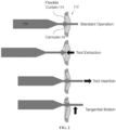
- the flexible curtain 116 accommodates both an in/out motion and a tangential motion of the tool 134, as shown in FIG. 2 . During normal operation, this flexibility allows the tool 134 to move relatively unobstructed, whereas during insertion/extraction of the tool 134, the flexible curtain 116 is pushed/pulled along with the tool 134.
- the tool cannula 118 can be integrated into the flexible curtain 116 to provide a substantially continuous fluid seal between the interior and exterior of the support structure 102.
- the tool cannula 118 forms a seal around the tool 134, allowing for relatively unobstructed tool motion (low friction) while maintaining the fluid seal.
- an interface between sterile and non-sterile surgical fields of the docking system 100 is shown.
- This interface is composed of a portion of the support structure 102 accommodating the imaging probe 130 along with the separation layer 110, configured such that the interface does not interfere with imaging capabilities.
- Components of the docking system 100 in the sterile field can be configured specifically to comply with surgical operating theater criteria for sterility, or can be formed of inexpensive materials and can be disposable. Regardless of how the flexible port 112 moves in response to tool movement, an imaging line of sight is maintained and remains unblocked, other than by the tool 134 itself.
- a lubricating fluid e.g., a lubricating liquid
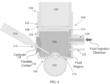
- a fluid-injection port 120 disposed extending through another opening in the sidewall 108 of the support structure 102, such that the fluid 136 can fill a portion of the interior (serving as a fluid region/cavity) between the separation layer 110 and the patient's eyeball 132.
- This fluid 136 serves the following purposes: (1) it maintains hydration or lubrication of the eyeball 132, (2) it maintains an internal pressure of the docking system 100 and can be used to balance a force of the retaining mechanism 114, and (3) it improves a quality of an imaging system by providing a fluid medium (such as for an OCT probe). It is noted that the flexible curtain 116 together with the tool cannula 118 maintain a fluid seal between the interior and exterior of the support structure 102. As shown in FIG.
- a pressure sensor 122 and a regulation valve 124 are each disposed extending through the sidewall 108 of the support structure 102, where the pressure sensor 122 measures the internal pressure of the docking system 100, and the regulation valve 124 allows for controlled release or removal of the fluid 136 in the event the internal pressure exceeds a specified threshold.
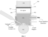
- FIG. 5 shows a docking system 500 according to additional embodiments. Certain features of the docking system 500 are similarly implemented as explained for the docking system 100, and repeated explanation of those features is omitted.
- the docking system 500 further includes a barrier layer 502, which is disposed within the interior of the support structure 102 between the separation layer 110 and the eyeball 132 to separate or compartmentalize the sterile field into an air region/cavity and a liquid region/cavity.
- the air region/cavity can contain air (or another gas or can be evacuated), and the barrier layer 502 forms a seal with the sidewall 108 of the support structure 102 to block the lubricating fluid 136 from entering the air region/cavity.
- the provision of the air region/cavity can further improve a scan quality of an imaging system.
- the barrier layer 502 can be formed of, or can include, a light transmissive material (e.g., at least about 80%, at least about 85%, or at least about 90% transmissive) relative to the electromagnetic radiation detected by the imaging probe 130.
- a docking system for intraocular surgery includes: (1) a support structure having a first end to accommodate an imaging probe, and a second end to accommodate an eyeball, the support structure including a sidewall; (2) a separation layer disposed within an interior of the support structure to separate the interior into a sterile field and a non-sterile field; (3) a flexible port disposed extending through the sidewall of the support structure, to accommodate a surgical tool; and (4) a retaining mechanism disposed adjacent to the second end of the support structure, to secure the eyeball relative to the support structure.
- the separation layer is light transmissive.
- the flexible port includes a flexible curtain and a tool cannula extending through the flexible curtain.
- the retaining mechanism includes a suction attachment.
- the docking system further includes a fluid-injection port disposed extending through the sidewall of the support structure, to allow introduction of a fluid into the sterile field.
- the docking system further includes a pressure sensor to measure an internal pressure in the sterile field.
- the docking system further includes a regulation valve disposed extending through the sidewall of the support structure, to allow release of the fluid from the sterile field.
- the docking system further includes a barrier layer disposed within the interior of the support structure to separate the sterile field into a first region and a second region, and wherein the fluid-injection port is disposed extending through the sidewall of the support structure adjacent to the second region, to allow introduction of the fluid into the second region of the sterile field.
- the barrier layer is light transmissive.
- a docking system for intraocular surgery includes: (1) a support structure including a sidewall having a first end and a second end, and defining a hollow interior; (2) a separation layer disposed within the interior of the support structure to separate the interior into a sterile field adjacent to the second end, and a non-sterile field adjacent to the first end; (3) a tool port disposed extending through the sidewall of the support structure adjacent to the sterile field; (4) a fluid-injection port disposed extending through the sidewall of the support structure adjacent to the sterile field; (5) a regulation valve disposed extending through the sidewall of the support structure adjacent to the sterile field; and (6) a retaining mechanism disposed adjacent to the second end of the support structure.
- the separation layer is light transmissive.
- the tool port includes a flexible curtain and a tool cannula extending through the flexible curtain.
- the retaining mechanism includes a suction attachment.
- the docking system further includes a pressure sensor disposed extending through the sidewall of the support structure adjacent to the sterile field.
- the docking system further includes a barrier layer disposed within the interior of the support structure to separate the sterile field into a first region and a second region, and wherein the fluid-injection port and the regulation valve are disposed extending through the sidewall of the support structure adjacent to the second region.
- the barrier layer is light transmissive.
- the first region contains a gas.
- a set refers to a collection of one or more objects.
- a set of objects can include a single object or multiple objects.
- Objects of a set also can be referred to as members of the set.
- Objects of a set can be the same or different.
- objects of a set can share one or more common characteristics.
- connection refers to an operational coupling or linking.
- Connected objects can be directly coupled to one another or can be indirectly coupled to one another, such as via one or more other objects.
- the terms “substantially” and “about” are used to describe and account for small variations.
- the terms can refer to instances in which the event or circumstance occurs precisely as well as instances in which the event or circumstance occurs to a close approximation.
- the terms can refer to a range of variation of less than or equal to ⁇ 10% of that numerical value, such as less than or equal to ⁇ 5%, less than or equal to ⁇ 4%, less than or equal to ⁇ 3%, less than or equal to ⁇ 2%, less than or equal to ⁇ 1%, less than or equal to ⁇ 0.5%, less than or equal to ⁇ 0.1%, or less than or equal to ⁇ 0.05%.
- a first numerical value can be "substantially” or “about” the same as a second numerical value if the first numerical value is within a range of variation of less than or equal to ⁇ 10% of the second numerical value, such as less than or equal to ⁇ 5%, less than or equal to ⁇ 4%, less than or equal to ⁇ 3%, less than or equal to ⁇ 2%, less than or equal to ⁇ 1%, less than or equal to ⁇ 0.5%, less than or equal to ⁇ 0.1%, or less than or equal to ⁇ 0.05%.
- an object provided "on,” “over,” “on top of,” or “below” another object can encompass cases where the former object is directly adjoining (e.g., in physical or direct contact with) the latter object, as well as cases where one or more intervening objects are located between the former object and the latter obj ect.
- concentrations, amounts, ratios, and other numerical values are sometimes presented herein in a range format. It is to be understood that such range format is used for convenience and brevity and should be understood flexibly to include numerical values explicitly specified as limits of a range, but also to include all individual numerical values or sub-ranges encompassed within that range as if each numerical value and sub-range is explicitly specified. For example, a range of about 1 to about 200 should be understood to include the explicitly recited limits of about 1 and about 200, but also to include individual values such as about 2, about 3, and about 4, and sub-ranges such as about 10 to about 50, about 20 to about 100, and so forth.
Landscapes
- Health & Medical Sciences (AREA)
- Life Sciences & Earth Sciences (AREA)
- Surgery (AREA)
- Ophthalmology & Optometry (AREA)
- Animal Behavior & Ethology (AREA)
- Nuclear Medicine, Radiotherapy & Molecular Imaging (AREA)
- Engineering & Computer Science (AREA)
- Biomedical Technology (AREA)
- Heart & Thoracic Surgery (AREA)
- Veterinary Medicine (AREA)
- Public Health (AREA)
- General Health & Medical Sciences (AREA)
- Vascular Medicine (AREA)
- Oral & Maxillofacial Surgery (AREA)
- Pathology (AREA)
- Medical Informatics (AREA)
- Molecular Biology (AREA)
- Physics & Mathematics (AREA)
- Optics & Photonics (AREA)
- Eye Examination Apparatus (AREA)
Description
- This disclosure generally relates to a physical interface between an imaging probe and an eyeball during intraocular surgery.
- Intraocular medical conditions are treated with delicate microsurgical procedures that rely on good visualization of delicate tissues within a small and constrained space of an eye. Optical coherence tomography (OCT) can be used to improve intraocular visualization by imaging small membranes and anatomical features to reveal features that would otherwise remain invisible or difficult to perceive by a surgeon, thereby improving surgical outcomes. In addition, OCT is capable of providing fast, small-scale, and accurate measurements which allow for the possibility of real-time guidance to the surgeon or to an autonomous robotic surgical system. In addition to OCT, a surgical microscope can be used to visualize features inside the eye.
- Despite the advantages of OCT systems and surgical microscopes, the quality of both imaging systems can suffer from the nature of a surgical environment. First, the constant motion of an eyeball beneath a stationary imaging system can result in high levels of noise and data distortion in a visualized area. Second, OCT scan quality in particular can be dependent on the presence of a fluid medium between an imaging probe and an anatomy to be scanned; thus maintaining an application of a fluid medium is desired to achieve a high level of scan quality. Further, the imaging system is located in a patient sterile field but cannot itself be adequately sterilized, thereby constraining its use and integration into other systems, such as robotic surgical systems.
- A docking system for intraocular surgery is known from
US 2011/319873 A1 . - It is against this background that a need arose to develop the embodiments described herein.
- Embodiments of this disclosure are directed to a physical interface between a probe of an imaging system, such as a surgical microscope or an OCT system, and an eyeball during intraocular surgery. In particular, in some embodiments, a docking system is provided to secure or stabilize the eyeball relative to the imaging probe, to allow for the use of surgical instruments or tools, and to facilitate real-time image acquisition during intraocular surgery.
- In some embodiments, a docking system is provided to secure an eyeball during intraocular surgery and constrain it relative to an imaging probe. The docking system includes a rigid support structure that is configured to accommodate and receive the imaging probe at one end of the support structure and to accommodate and receive the eyeball at another end of the support structure. A separation layer is provided within the support structure to compartmentalize or separate an interior of the support structure into a patient sterile field and a non-sterile imaging probe field. A retaining mechanism is provided at the end of the support structure that receives the eyeball, such as a suction attachment, to secure the eyeball relative to the support structure. One or more flexible ports are provided extending through a sidewall of the support structure to allow surgical instruments or tools to be inserted through the flexible ports.
- Embodiments of the docking system can be used to (1) physically stabilize a position and an orientation of an eye during intraocular surgical procedures, (2) improve a scan quality of an imaging system, such as an OCT system or a surgical microscope, (3) provide access to the eye through a compliant or flexible port that accounts for a remote center of motion (RCM) of tool movement, and (4) maintain or control an intraocular pressure of the eye to a stable, desired level during surgical procedures.
- Other aspects and embodiments of this disclosure are also contemplated. The foregoing summary and the following detailed description are not meant to restrict this disclosure to any particular embodiment but are merely meant to describe some embodiments of this disclosure.
- For a better understanding of the nature and objects of some embodiments of this disclosure, reference should be made to the following detailed description taken in conjunction with the accompanying drawings.
-
FIG. 1 shows a docking system according to some embodiments. -
FIG. 2 shows a flexible port of the docking system ofFIG. 1 , according to some embodiments. -
FIG. 3 shows an interface between sterile and non-sterile surgical fields of the docking system ofFIG. 1 , according to some embodiments. -
FIG. 4 shows a lubricating fluid introduced through a fluid-injection port of the docking system ofFIG. 1 , according to some embodiments. -
FIG. 5 shows a docking system according to additional embodiments. - Referring to
FIG. 1 , animaging probe 130 is located at a distance from aneyeball 132. According to some embodiments, adocking system 100 is provided that includes arigid support structure 102 having afirst end 104 that accommodates, receives, and fits over theimaging probe 130, and having asecond end 106 that accommodates and receives theeyeball 132 to secure theeyeball 132 in place relative to theimaging probe 130. Thesupport structure 102 is hollow and includes asidewall 108 that forms a generally cylindrical shape. Aseparation layer 110 is disposed within an interior of thesupport structure 102 between theimaging probe 130 and theeyeball 132 to separate a patient sterile field from a non-sterile field of theimaging probe 130, without interfering with imaging capabilities of theimaging probe 130. For example, theseparation layer 110 can be formed of, or can include, a light transmissive material (e.g., at least about 80%, at least about 85%, or at least about 90% transmissive) relative to electromagnetic radiation detected by theimaging probe 130. At least oneflexible tool port 112 is disposed extending through an opening in thesidewall 108 of thesupport structure 102, such that a surgical instrument ortool 134 can pass through theflexible port 112, extending to an RCM at or inside theeyeball 132. Theflexible port 112 can accommodate tool movement during a surgical procedure as well as tool insertion and extraction. Aretaining mechanism 114 is disposed at or adjacent to thesecond end 106 of thesupport structure 102, such a passive suction attachment, for securing theeyeball 132 relative to thesupport structure 102. As shown inFIG. 1 , the suction attachment is generally circular in geometry, such as in the form of a ring, and can cover an entire anterior segment of the eyeball 132 (comea/limbus/sclera). - Referring to
FIG. 2 , theflexible port 112 of thedocking system 100 is shown. Theflexible port 112 includes two main components: (1) aflexible curtain 116, such as formed of an elastomer, that maintains a fluid seal between the interior and an exterior of thesupport structure 102 and (2) atool cannula 118 that extends through theflexible curtain 116 and forms a seal with thesurgical tool 134. Theflexible curtain 116 accommodates both an in/out motion and a tangential motion of thetool 134, as shown inFIG. 2 . During normal operation, this flexibility allows thetool 134 to move relatively unobstructed, whereas during insertion/extraction of thetool 134, theflexible curtain 116 is pushed/pulled along with thetool 134. Thetool cannula 118 can be integrated into theflexible curtain 116 to provide a substantially continuous fluid seal between the interior and exterior of thesupport structure 102. Thetool cannula 118 forms a seal around thetool 134, allowing for relatively unobstructed tool motion (low friction) while maintaining the fluid seal. - Referring to
FIG. 3 , an interface between sterile and non-sterile surgical fields of thedocking system 100 is shown. This interface is composed of a portion of thesupport structure 102 accommodating theimaging probe 130 along with theseparation layer 110, configured such that the interface does not interfere with imaging capabilities. Components of thedocking system 100 in the sterile field can be configured specifically to comply with surgical operating theater criteria for sterility, or can be formed of inexpensive materials and can be disposable. Regardless of how theflexible port 112 moves in response to tool movement, an imaging line of sight is maintained and remains unblocked, other than by thetool 134 itself. - Referring to
FIG. 4 in combination withFIG. 1 , a lubricating fluid (e.g., a lubricating liquid) 136 is introduced through a fluid-injection port 120 disposed extending through another opening in thesidewall 108 of thesupport structure 102, such that thefluid 136 can fill a portion of the interior (serving as a fluid region/cavity) between theseparation layer 110 and the patient'seyeball 132. Thisfluid 136 serves the following purposes: (1) it maintains hydration or lubrication of theeyeball 132, (2) it maintains an internal pressure of thedocking system 100 and can be used to balance a force of theretaining mechanism 114, and (3) it improves a quality of an imaging system by providing a fluid medium (such as for an OCT probe). It is noted that theflexible curtain 116 together with thetool cannula 118 maintain a fluid seal between the interior and exterior of thesupport structure 102. As shown inFIG. 1 , apressure sensor 122 and aregulation valve 124 are each disposed extending through thesidewall 108 of thesupport structure 102, where thepressure sensor 122 measures the internal pressure of thedocking system 100, and theregulation valve 124 allows for controlled release or removal of thefluid 136 in the event the internal pressure exceeds a specified threshold. -
FIG. 5 shows adocking system 500 according to additional embodiments. Certain features of thedocking system 500 are similarly implemented as explained for thedocking system 100, and repeated explanation of those features is omitted. As shown inFIG. 5 , thedocking system 500 further includes abarrier layer 502, which is disposed within the interior of thesupport structure 102 between theseparation layer 110 and theeyeball 132 to separate or compartmentalize the sterile field into an air region/cavity and a liquid region/cavity. The air region/cavity can contain air (or another gas or can be evacuated), and thebarrier layer 502 forms a seal with thesidewall 108 of thesupport structure 102 to block the lubricatingfluid 136 from entering the air region/cavity. The provision of the air region/cavity can further improve a scan quality of an imaging system. Thebarrier layer 502 can be formed of, or can include, a light transmissive material (e.g., at least about 80%, at least about 85%, or at least about 90% transmissive) relative to the electromagnetic radiation detected by theimaging probe 130. - The following are example embodiments of this disclosure.
- In some embodiments, a docking system for intraocular surgery includes: (1) a support structure having a first end to accommodate an imaging probe, and a second end to accommodate an eyeball, the support structure including a sidewall; (2) a separation layer disposed within an interior of the support structure to separate the interior into a sterile field and a non-sterile field; (3) a flexible port disposed extending through the sidewall of the support structure, to accommodate a surgical tool; and (4) a retaining mechanism disposed adjacent to the second end of the support structure, to secure the eyeball relative to the support structure.
- In some embodiments, the separation layer is light transmissive.
- In some embodiments, the flexible port includes a flexible curtain and a tool cannula extending through the flexible curtain.
- In some embodiments, the retaining mechanism includes a suction attachment.
- In some embodiments, the docking system further includes a fluid-injection port disposed extending through the sidewall of the support structure, to allow introduction of a fluid into the sterile field.
- In some embodiments, the docking system further includes a pressure sensor to measure an internal pressure in the sterile field.
- In some embodiments, the docking system further includes a regulation valve disposed extending through the sidewall of the support structure, to allow release of the fluid from the sterile field.
- In some embodiments, the docking system further includes a barrier layer disposed within the interior of the support structure to separate the sterile field into a first region and a second region, and wherein the fluid-injection port is disposed extending through the sidewall of the support structure adjacent to the second region, to allow introduction of the fluid into the second region of the sterile field.
- In some embodiments, the barrier layer is light transmissive.
- In additional embodiments, a docking system for intraocular surgery includes: (1) a support structure including a sidewall having a first end and a second end, and defining a hollow interior; (2) a separation layer disposed within the interior of the support structure to separate the interior into a sterile field adjacent to the second end, and a non-sterile field adjacent to the first end; (3) a tool port disposed extending through the sidewall of the support structure adjacent to the sterile field; (4) a fluid-injection port disposed extending through the sidewall of the support structure adjacent to the sterile field; (5) a regulation valve disposed extending through the sidewall of the support structure adjacent to the sterile field; and (6) a retaining mechanism disposed adjacent to the second end of the support structure.
- In some embodiments, the separation layer is light transmissive.
- In some embodiments, the tool port includes a flexible curtain and a tool cannula extending through the flexible curtain.
- In some embodiments, the retaining mechanism includes a suction attachment.
- In some embodiments, the docking system further includes a pressure sensor disposed extending through the sidewall of the support structure adjacent to the sterile field.
- In some embodiments, the docking system further includes a barrier layer disposed within the interior of the support structure to separate the sterile field into a first region and a second region, and wherein the fluid-injection port and the regulation valve are disposed extending through the sidewall of the support structure adjacent to the second region.
- In some embodiments, the barrier layer is light transmissive.
- In some embodiments, the first region contains a gas.
- As used herein, the singular terms "a," "an," and "the" may include plural referents unless the context clearly dictates otherwise. Thus, for example, reference to an object may include multiple objects unless the context clearly dictates otherwise.
- As used herein, the term "set" refers to a collection of one or more objects. Thus, for example, a set of objects can include a single object or multiple objects. Objects of a set also can be referred to as members of the set. Objects of a set can be the same or different. In some instances, objects of a set can share one or more common characteristics.
- As used herein, the terms "connect," "connected," and "connection" refer to an operational coupling or linking. Connected objects can be directly coupled to one another or can be indirectly coupled to one another, such as via one or more other objects.
- As used herein, the terms "substantially" and "about" are used to describe and account for small variations. When used in conjunction with an event or circumstance, the terms can refer to instances in which the event or circumstance occurs precisely as well as instances in which the event or circumstance occurs to a close approximation. For example, when used in conjunction with a numerical value, the terms can refer to a range of variation of less than or equal to ±10% of that numerical value, such as less than or equal to ±5%, less than or equal to ±4%, less than or equal to ±3%, less than or equal to ±2%, less than or equal to ±1%, less than or equal to ±0.5%, less than or equal to ±0.1%, or less than or equal to ±0.05%. For example, a first numerical value can be "substantially" or "about" the same as a second numerical value if the first numerical value is within a range of variation of less than or equal to ±10% of the second numerical value, such as less than or equal to ±5%, less than or equal to ±4%, less than or equal to ±3%, less than or equal to ±2%, less than or equal to ±1%, less than or equal to ±0.5%, less than or equal to ±0.1%, or less than or equal to ±0.05%.
- In the description of some embodiments, an object provided "on," "over," "on top of," or "below" another object can encompass cases where the former object is directly adjoining (e.g., in physical or direct contact with) the latter object, as well as cases where one or more intervening objects are located between the former object and the latter obj ect.
- Additionally, concentrations, amounts, ratios, and other numerical values are sometimes presented herein in a range format. It is to be understood that such range format is used for convenience and brevity and should be understood flexibly to include numerical values explicitly specified as limits of a range, but also to include all individual numerical values or sub-ranges encompassed within that range as if each numerical value and sub-range is explicitly specified. For example, a range of about 1 to about 200 should be understood to include the explicitly recited limits of about 1 and about 200, but also to include individual values such as about 2, about 3, and about 4, and sub-ranges such as about 10 to about 50, about 20 to about 100, and so forth.
- The invention is defined in the appended claims.
Claims (15)
- A docking system (100) for intraocular surgery, comprisinga support structure (102) having a first end (104) to accommodate an imaging probe (130), and a second end (106) to accommodate an eyeball, the support structure including a sidewall; a separation layer (110) disposed within an interior of the support structure to separate the interior into a sterile field and a non-sterile field;a port (112) disposed extending through the sidewall of the support structure, to accommodate a surgical tool (134); anda retaining mechanism (114) disposed adjacent to the second end of the support structure, to secure the eyeball relative to the support structure;characterized in that the port is a flexible port.
- The docking system of claim 1, wherein the separation layer (110) is light transmissive.
- The docking system of claim 1, wherein the flexible port includes a flexible curtain. (116) and a tool cannula (118) extending through the flexible curtain.
- The docking system of claim 1, wherein the retaining mechanism includes a suction attachment.
- The docking system of claim 1, further comprising a fluid-injection port (120) disposed extending through the sidewall of the support structure, to allow introduction of a fluid into the sterile field.
- The docking system of claim 5, further comprising one or more of (a) a pressure sensor (122) to measure an internal pressure in the sterile field, (b) a regulation valve (124) disposed extending through the sidewall of the support structure, to allow release of the fluid from the sterile field, and (c) a barrier layer disposed within the interior of the support structure to separate the sterile field into a first region and a second region, and wherein the fluid-injection port is disposed extending through the sidewall of the support structure adjacent to the second region, to allow introduction of the fluid into the second region of the sterile field.
- The docking system of claim 6(c), wherein the barrier layer is light transmissive.
- The docking system of claim 1, further comprising:the flexible port (112) being a tool port disposed extending through the sidewall of the support structure adjacent to the sterile field;a fluid-injection port (120) disposed extending through the sidewall of the support structure adj acent to the sterile field; anda regulation valve (124) disposed extending through the sidewall of the support structure adjacent to the sterile field.
- The docking system of claim 8, wherein the separation layer is light transmissive.
- The docking system of claim 8, wherein the tool port includes a flexible curtain and a tool cannula extending through the flexible curtain.
- The docking system of claim 8, wherein the retaining mechanism includes a suction attachment.
- The docking system of claim 8, further comprising a pressure sensor (122) disposed extending through the sidewall of the support structure adjacent to the sterile field.
- The docking system of claim 8, further comprising a barrier layer disposed within the interior of the support structure to separate the sterile field into a first region and a second region, and wherein the fluid-injection port and the regulation valve are disposed extending through the sidewall of the support structure adjacent to the second region.
- The docking system of claim 13, wherein the barrier layer is light transmissive.
- The docking system of claim 13, wherein the first region contains a gas.
Applications Claiming Priority (2)
| Application Number | Priority Date | Filing Date | Title |
|---|---|---|---|
| US201862645517P | 2018-03-20 | 2018-03-20 | |
| PCT/US2019/022986 WO2019183106A1 (en) | 2018-03-20 | 2019-03-19 | Docking system to stabilize eyeball during intraocular surgery |
Publications (3)
| Publication Number | Publication Date |
|---|---|
| EP3768205A1 EP3768205A1 (en) | 2021-01-27 |
| EP3768205A4 EP3768205A4 (en) | 2021-12-22 |
| EP3768205B1 true EP3768205B1 (en) | 2023-05-03 |
Family
ID=67987490
Family Applications (1)
| Application Number | Title | Priority Date | Filing Date |
|---|---|---|---|
| EP19772473.5A Active EP3768205B1 (en) | 2018-03-20 | 2019-03-19 | Docking system to stabilize eyeball during intraocular surgery |
Country Status (3)
| Country | Link |
|---|---|
| US (1) | US12016740B2 (en) |
| EP (1) | EP3768205B1 (en) |
| WO (1) | WO2019183106A1 (en) |
Families Citing this family (6)
| Publication number | Priority date | Publication date | Assignee | Title |
|---|---|---|---|---|
| WO2019222228A1 (en) | 2018-05-15 | 2019-11-21 | The Regents Of The University Of California | System and method for automated image-guided robotic intraocular surgery |
| US12458533B2 (en) | 2020-08-13 | 2025-11-04 | Forsight Robotics Ltd. | Capsulorhexis apparatus and method |
| WO2022254335A1 (en) | 2021-06-01 | 2022-12-08 | Forsight Robotics Ltd. | Kinematic structures and sterile drapes for robotic microsurgical procedures |
| WO2023062470A1 (en) | 2021-10-17 | 2023-04-20 | Forsight Robotics Ltd. | One-sided robotic surgical procedure |
| JP2025037404A (en) * | 2023-09-06 | 2025-03-18 | 学校法人福岡大学 | Trocar for ophthalmic surgery and trocar system equipped with trocar for ophthalmic surgery |
| EP4717190A1 (en) | 2024-09-27 | 2026-04-01 | Carl Zeiss Meditec AG | Eye gripping device and eye manipulation system |
Family Cites Families (11)
| Publication number | Priority date | Publication date | Assignee | Title |
|---|---|---|---|---|
| FR2489141A1 (en) * | 1980-09-03 | 1982-03-05 | Sevifra | SURGICAL APPARATUS FOR PRECISE CUTTING OF THE CORNEA |
| US5486188A (en) * | 1993-11-15 | 1996-01-23 | Smith; Alan D. | Keratoscopic surgical instrument for making radial and arcuate corneal incisions |
| US5989272A (en) * | 1998-10-05 | 1999-11-23 | Barron Precision Instruments L.L.C. | Keratome for performing eye surgery and method for using same |
| US6899707B2 (en) * | 2001-01-29 | 2005-05-31 | Intralase Corp. | Applanation lens and method for ophthalmic surgical applications |
| US7955324B2 (en) * | 2005-10-21 | 2011-06-07 | Technolas Perfect Vision Gmbh | Cornea contact system |
| EP2334271B1 (en) * | 2008-08-25 | 2015-04-08 | WaveLight GmbH | Coupling of an eye to a laser device |
| CA2769091A1 (en) * | 2009-07-24 | 2011-01-27 | Lensar, Inc. | Liquid holding interface device for ophthalmic laser procedures |
| SI2515774T1 (en) * | 2009-12-23 | 2014-06-30 | Alcon Research, Ltd. | Ophthalmic valved trocar cannula |
| US8845624B2 (en) * | 2010-06-25 | 2014-09-30 | Alcon LexSx, Inc. | Adaptive patient interface |
| AU2011320709B2 (en) * | 2010-10-26 | 2015-12-17 | Alcon Inc. | Ophthalmoscopic surgical contact lens |
| US9987165B2 (en) * | 2012-11-02 | 2018-06-05 | Optimedica Corporation | Liquid optical interface for laser eye surgery system |
-
2019
- 2019-03-19 EP EP19772473.5A patent/EP3768205B1/en active Active
- 2019-03-19 WO PCT/US2019/022986 patent/WO2019183106A1/en not_active Ceased
-
2020
- 2020-09-15 US US17/021,925 patent/US12016740B2/en active Active
Also Published As
| Publication number | Publication date |
|---|---|
| EP3768205A1 (en) | 2021-01-27 |
| US20210000566A1 (en) | 2021-01-07 |
| EP3768205A4 (en) | 2021-12-22 |
| US12016740B2 (en) | 2024-06-25 |
| WO2019183106A1 (en) | 2019-09-26 |
Similar Documents
| Publication | Publication Date | Title |
|---|---|---|
| US12016740B2 (en) | Docking system to stabilize eyeball during intraocular surgery | |
| US11206970B2 (en) | Illuminated ophthalmic infusion line and associated devices, systems, and methods | |
| US7553278B2 (en) | Protective cap for arthroscopic instruments | |
| US8870747B2 (en) | Scraping fluid removal in a surgical access device | |
| US3958566A (en) | Suction control device for an endoscope | |
| EP2113214B1 (en) | Absorbing fluids in a surgical access device | |
| US8870749B2 (en) | Arrangement for minimal access surgery | |
| US20080177239A1 (en) | Trocar cannula system | |
| US20090270817A1 (en) | Fluid removal in a surgical access device | |
| EP2002812A1 (en) | Self sealing cannula/aperture closure cannula | |
| US20090270813A1 (en) | Wicking fluid management in a surgical access device | |
| JP2023512193A (en) | Visualization Devices, Systems, and Methods for Otology and Other Applications | |
| US10729322B2 (en) | Unreversed prism gonioscopy lens and carrier assembly | |
| TW200803817A (en) | Surgical cassette with improved air filtering | |
| US12342992B2 (en) | Instrument port with fluid flush system | |
| RU2703502C2 (en) | Oct transparent surgical instruments and methods | |
| EP2979614A1 (en) | Trocar | |
| KR20150135533A (en) | Surgical adapter for use with an endoscope | |
| JP2022082516A (en) | Arthroscopic medical implements and assemblies | |
| JP2026500827A (en) | Docking station for use in ophthalmic procedures | |
| US20130237753A1 (en) | Surgical interface for use with endoscope | |
| US20110301411A1 (en) | Fluidic endoscope tip locator | |
| WO2014126757A2 (en) | Surgical interface for use with endoscope | |
| JP2022082517A (en) | Arthroscopic medical implements and assemblies | |
| Bhende et al. | Commentary: Ocular endoscopy: An eye into the eye |
Legal Events
| Date | Code | Title | Description |
|---|---|---|---|
| STAA | Information on the status of an ep patent application or granted ep patent |
Free format text: STATUS: THE INTERNATIONAL PUBLICATION HAS BEEN MADE |
|
| PUAI | Public reference made under article 153(3) epc to a published international application that has entered the european phase |
Free format text: ORIGINAL CODE: 0009012 |
|
| STAA | Information on the status of an ep patent application or granted ep patent |
Free format text: STATUS: REQUEST FOR EXAMINATION WAS MADE |
|
| 17P | Request for examination filed |
Effective date: 20200925 |
|
| AK | Designated contracting states |
Kind code of ref document: A1 Designated state(s): AL AT BE BG CH CY CZ DE DK EE ES FI FR GB GR HR HU IE IS IT LI LT LU LV MC MK MT NL NO PL PT RO RS SE SI SK SM TR |
|
| AX | Request for extension of the european patent |
Extension state: BA ME |
|
| DAV | Request for validation of the european patent (deleted) | ||
| DAX | Request for extension of the european patent (deleted) | ||
| A4 | Supplementary search report drawn up and despatched |
Effective date: 20211124 |
|
| RIC1 | Information provided on ipc code assigned before grant |
Ipc: A61B 17/32 20060101ALI20211118BHEP Ipc: A61F 9/009 20060101ALI20211118BHEP Ipc: A61F 9/007 20060101ALI20211118BHEP Ipc: A61F 9/00 20060101AFI20211118BHEP |
|
| GRAP | Despatch of communication of intention to grant a patent |
Free format text: ORIGINAL CODE: EPIDOSNIGR1 |
|
| STAA | Information on the status of an ep patent application or granted ep patent |
Free format text: STATUS: GRANT OF PATENT IS INTENDED |
|
| INTG | Intention to grant announced |
Effective date: 20221021 |
|
| GRAS | Grant fee paid |
Free format text: ORIGINAL CODE: EPIDOSNIGR3 |
|
| GRAA | (expected) grant |
Free format text: ORIGINAL CODE: 0009210 |
|
| STAA | Information on the status of an ep patent application or granted ep patent |
Free format text: STATUS: THE PATENT HAS BEEN GRANTED |
|
| AK | Designated contracting states |
Kind code of ref document: B1 Designated state(s): AL AT BE BG CH CY CZ DE DK EE ES FI FR GB GR HR HU IE IS IT LI LT LU LV MC MK MT NL NO PL PT RO RS SE SI SK SM TR |
|
| REG | Reference to a national code |
Ref country code: GB Ref legal event code: FG4D |
|
| REG | Reference to a national code |
Ref country code: AT Ref legal event code: REF Ref document number: 1563967 Country of ref document: AT Kind code of ref document: T Effective date: 20230515 Ref country code: CH Ref legal event code: EP |
|
| REG | Reference to a national code |
Ref country code: DE Ref legal event code: R096 Ref document number: 602019028437 Country of ref document: DE |
|
| REG | Reference to a national code |
Ref country code: IE Ref legal event code: FG4D |
|
| REG | Reference to a national code |
Ref country code: LT Ref legal event code: MG9D |
|
| REG | Reference to a national code |
Ref country code: NL Ref legal event code: MP Effective date: 20230503 |
|
| REG | Reference to a national code |
Ref country code: AT Ref legal event code: MK05 Ref document number: 1563967 Country of ref document: AT Kind code of ref document: T Effective date: 20230503 |
|
| PG25 | Lapsed in a contracting state [announced via postgrant information from national office to epo] |
Ref country code: SE Free format text: LAPSE BECAUSE OF FAILURE TO SUBMIT A TRANSLATION OF THE DESCRIPTION OR TO PAY THE FEE WITHIN THE PRESCRIBED TIME-LIMIT Effective date: 20230503 Ref country code: PT Free format text: LAPSE BECAUSE OF FAILURE TO SUBMIT A TRANSLATION OF THE DESCRIPTION OR TO PAY THE FEE WITHIN THE PRESCRIBED TIME-LIMIT Effective date: 20230904 Ref country code: NO Free format text: LAPSE BECAUSE OF FAILURE TO SUBMIT A TRANSLATION OF THE DESCRIPTION OR TO PAY THE FEE WITHIN THE PRESCRIBED TIME-LIMIT Effective date: 20230803 Ref country code: NL Free format text: LAPSE BECAUSE OF FAILURE TO SUBMIT A TRANSLATION OF THE DESCRIPTION OR TO PAY THE FEE WITHIN THE PRESCRIBED TIME-LIMIT Effective date: 20230503 Ref country code: ES Free format text: LAPSE BECAUSE OF FAILURE TO SUBMIT A TRANSLATION OF THE DESCRIPTION OR TO PAY THE FEE WITHIN THE PRESCRIBED TIME-LIMIT Effective date: 20230503 Ref country code: AT Free format text: LAPSE BECAUSE OF FAILURE TO SUBMIT A TRANSLATION OF THE DESCRIPTION OR TO PAY THE FEE WITHIN THE PRESCRIBED TIME-LIMIT Effective date: 20230503 |
|
| PG25 | Lapsed in a contracting state [announced via postgrant information from national office to epo] |
Ref country code: RS Free format text: LAPSE BECAUSE OF FAILURE TO SUBMIT A TRANSLATION OF THE DESCRIPTION OR TO PAY THE FEE WITHIN THE PRESCRIBED TIME-LIMIT Effective date: 20230503 Ref country code: PL Free format text: LAPSE BECAUSE OF FAILURE TO SUBMIT A TRANSLATION OF THE DESCRIPTION OR TO PAY THE FEE WITHIN THE PRESCRIBED TIME-LIMIT Effective date: 20230503 Ref country code: LV Free format text: LAPSE BECAUSE OF FAILURE TO SUBMIT A TRANSLATION OF THE DESCRIPTION OR TO PAY THE FEE WITHIN THE PRESCRIBED TIME-LIMIT Effective date: 20230503 Ref country code: LT Free format text: LAPSE BECAUSE OF FAILURE TO SUBMIT A TRANSLATION OF THE DESCRIPTION OR TO PAY THE FEE WITHIN THE PRESCRIBED TIME-LIMIT Effective date: 20230503 Ref country code: IS Free format text: LAPSE BECAUSE OF FAILURE TO SUBMIT A TRANSLATION OF THE DESCRIPTION OR TO PAY THE FEE WITHIN THE PRESCRIBED TIME-LIMIT Effective date: 20230903 Ref country code: HR Free format text: LAPSE BECAUSE OF FAILURE TO SUBMIT A TRANSLATION OF THE DESCRIPTION OR TO PAY THE FEE WITHIN THE PRESCRIBED TIME-LIMIT Effective date: 20230503 Ref country code: GR Free format text: LAPSE BECAUSE OF FAILURE TO SUBMIT A TRANSLATION OF THE DESCRIPTION OR TO PAY THE FEE WITHIN THE PRESCRIBED TIME-LIMIT Effective date: 20230804 |
|
| PG25 | Lapsed in a contracting state [announced via postgrant information from national office to epo] |
Ref country code: FI Free format text: LAPSE BECAUSE OF FAILURE TO SUBMIT A TRANSLATION OF THE DESCRIPTION OR TO PAY THE FEE WITHIN THE PRESCRIBED TIME-LIMIT Effective date: 20230503 |
|
| PG25 | Lapsed in a contracting state [announced via postgrant information from national office to epo] |
Ref country code: SK Free format text: LAPSE BECAUSE OF FAILURE TO SUBMIT A TRANSLATION OF THE DESCRIPTION OR TO PAY THE FEE WITHIN THE PRESCRIBED TIME-LIMIT Effective date: 20230503 |
|
| PG25 | Lapsed in a contracting state [announced via postgrant information from national office to epo] |
Ref country code: SM Free format text: LAPSE BECAUSE OF FAILURE TO SUBMIT A TRANSLATION OF THE DESCRIPTION OR TO PAY THE FEE WITHIN THE PRESCRIBED TIME-LIMIT Effective date: 20230503 Ref country code: SK Free format text: LAPSE BECAUSE OF FAILURE TO SUBMIT A TRANSLATION OF THE DESCRIPTION OR TO PAY THE FEE WITHIN THE PRESCRIBED TIME-LIMIT Effective date: 20230503 Ref country code: RO Free format text: LAPSE BECAUSE OF FAILURE TO SUBMIT A TRANSLATION OF THE DESCRIPTION OR TO PAY THE FEE WITHIN THE PRESCRIBED TIME-LIMIT Effective date: 20230503 Ref country code: EE Free format text: LAPSE BECAUSE OF FAILURE TO SUBMIT A TRANSLATION OF THE DESCRIPTION OR TO PAY THE FEE WITHIN THE PRESCRIBED TIME-LIMIT Effective date: 20230503 Ref country code: DK Free format text: LAPSE BECAUSE OF FAILURE TO SUBMIT A TRANSLATION OF THE DESCRIPTION OR TO PAY THE FEE WITHIN THE PRESCRIBED TIME-LIMIT Effective date: 20230503 Ref country code: CZ Free format text: LAPSE BECAUSE OF FAILURE TO SUBMIT A TRANSLATION OF THE DESCRIPTION OR TO PAY THE FEE WITHIN THE PRESCRIBED TIME-LIMIT Effective date: 20230503 |
|
| REG | Reference to a national code |
Ref country code: DE Ref legal event code: R097 Ref document number: 602019028437 Country of ref document: DE |
|
| PLBE | No opposition filed within time limit |
Free format text: ORIGINAL CODE: 0009261 |
|
| STAA | Information on the status of an ep patent application or granted ep patent |
Free format text: STATUS: NO OPPOSITION FILED WITHIN TIME LIMIT |
|
| 26N | No opposition filed |
Effective date: 20240206 |
|
| PG25 | Lapsed in a contracting state [announced via postgrant information from national office to epo] |
Ref country code: SI Free format text: LAPSE BECAUSE OF FAILURE TO SUBMIT A TRANSLATION OF THE DESCRIPTION OR TO PAY THE FEE WITHIN THE PRESCRIBED TIME-LIMIT Effective date: 20230503 |
|
| PG25 | Lapsed in a contracting state [announced via postgrant information from national office to epo] |
Ref country code: SI Free format text: LAPSE BECAUSE OF FAILURE TO SUBMIT A TRANSLATION OF THE DESCRIPTION OR TO PAY THE FEE WITHIN THE PRESCRIBED TIME-LIMIT Effective date: 20230503 Ref country code: IT Free format text: LAPSE BECAUSE OF FAILURE TO SUBMIT A TRANSLATION OF THE DESCRIPTION OR TO PAY THE FEE WITHIN THE PRESCRIBED TIME-LIMIT Effective date: 20230503 |
|
| REG | Reference to a national code |
Ref country code: CH Ref legal event code: PL |
|
| PG25 | Lapsed in a contracting state [announced via postgrant information from national office to epo] |
Ref country code: BG Free format text: LAPSE BECAUSE OF FAILURE TO SUBMIT A TRANSLATION OF THE DESCRIPTION OR TO PAY THE FEE WITHIN THE PRESCRIBED TIME-LIMIT Effective date: 20230503 |
|
| PG25 | Lapsed in a contracting state [announced via postgrant information from national office to epo] |
Ref country code: LU Free format text: LAPSE BECAUSE OF NON-PAYMENT OF DUE FEES Effective date: 20240319 |
|
| PG25 | Lapsed in a contracting state [announced via postgrant information from national office to epo] |
Ref country code: MC Free format text: LAPSE BECAUSE OF FAILURE TO SUBMIT A TRANSLATION OF THE DESCRIPTION OR TO PAY THE FEE WITHIN THE PRESCRIBED TIME-LIMIT Effective date: 20230503 |
|
| PG25 | Lapsed in a contracting state [announced via postgrant information from national office to epo] |
Ref country code: MC Free format text: LAPSE BECAUSE OF FAILURE TO SUBMIT A TRANSLATION OF THE DESCRIPTION OR TO PAY THE FEE WITHIN THE PRESCRIBED TIME-LIMIT Effective date: 20230503 Ref country code: LU Free format text: LAPSE BECAUSE OF NON-PAYMENT OF DUE FEES Effective date: 20240319 Ref country code: BG Free format text: LAPSE BECAUSE OF FAILURE TO SUBMIT A TRANSLATION OF THE DESCRIPTION OR TO PAY THE FEE WITHIN THE PRESCRIBED TIME-LIMIT Effective date: 20230503 |
|
| REG | Reference to a national code |
Ref country code: BE Ref legal event code: MM Effective date: 20240331 |
|
| PG25 | Lapsed in a contracting state [announced via postgrant information from national office to epo] |
Ref country code: BE Free format text: LAPSE BECAUSE OF NON-PAYMENT OF DUE FEES Effective date: 20240331 |
|
| PG25 | Lapsed in a contracting state [announced via postgrant information from national office to epo] |
Ref country code: IE Free format text: LAPSE BECAUSE OF NON-PAYMENT OF DUE FEES Effective date: 20240319 |
|
| PG25 | Lapsed in a contracting state [announced via postgrant information from national office to epo] |
Ref country code: IE Free format text: LAPSE BECAUSE OF NON-PAYMENT OF DUE FEES Effective date: 20240319 Ref country code: BE Free format text: LAPSE BECAUSE OF NON-PAYMENT OF DUE FEES Effective date: 20240331 Ref country code: CH Free format text: LAPSE BECAUSE OF NON-PAYMENT OF DUE FEES Effective date: 20240331 |
|
| PG25 | Lapsed in a contracting state [announced via postgrant information from national office to epo] |
Ref country code: CY Free format text: LAPSE BECAUSE OF FAILURE TO SUBMIT A TRANSLATION OF THE DESCRIPTION OR TO PAY THE FEE WITHIN THE PRESCRIBED TIME-LIMIT; INVALID AB INITIO Effective date: 20190319 |
|
| PG25 | Lapsed in a contracting state [announced via postgrant information from national office to epo] |
Ref country code: HU Free format text: LAPSE BECAUSE OF FAILURE TO SUBMIT A TRANSLATION OF THE DESCRIPTION OR TO PAY THE FEE WITHIN THE PRESCRIBED TIME-LIMIT; INVALID AB INITIO Effective date: 20190319 |
|
| PG25 | Lapsed in a contracting state [announced via postgrant information from national office to epo] |
Ref country code: TR Free format text: LAPSE BECAUSE OF FAILURE TO SUBMIT A TRANSLATION OF THE DESCRIPTION OR TO PAY THE FEE WITHIN THE PRESCRIBED TIME-LIMIT Effective date: 20230503 |
|
| PGFP | Annual fee paid to national office [announced via postgrant information from national office to epo] |
Ref country code: GB Payment date: 20260327 Year of fee payment: 8 |
|
| PGFP | Annual fee paid to national office [announced via postgrant information from national office to epo] |
Ref country code: DE Payment date: 20260327 Year of fee payment: 8 |
|
| PGFP | Annual fee paid to national office [announced via postgrant information from national office to epo] |
Ref country code: FR Payment date: 20260325 Year of fee payment: 8 |