EP3767897B1 - Load balancing method - Google Patents
Load balancing method Download PDFInfo
- Publication number
- EP3767897B1 EP3767897B1 EP19784281.8A EP19784281A EP3767897B1 EP 3767897 B1 EP3767897 B1 EP 3767897B1 EP 19784281 A EP19784281 A EP 19784281A EP 3767897 B1 EP3767897 B1 EP 3767897B1
- Authority
- EP
- European Patent Office
- Prior art keywords
- probe
- load
- packet
- path
- channel
- Prior art date
- Legal status (The legal status is an assumption and is not a legal conclusion. Google has not performed a legal analysis and makes no representation as to the accuracy of the status listed.)
- Active
Links
Images






Classifications
-
- H—ELECTRICITY
- H04—ELECTRIC COMMUNICATION TECHNIQUE
- H04L—TRANSMISSION OF DIGITAL INFORMATION, e.g. TELEGRAPHIC COMMUNICATION
- H04L47/00—Traffic control in data switching networks
- H04L47/10—Flow control; Congestion control
- H04L47/11—Identifying congestion
-
- H—ELECTRICITY
- H04—ELECTRIC COMMUNICATION TECHNIQUE
- H04L—TRANSMISSION OF DIGITAL INFORMATION, e.g. TELEGRAPHIC COMMUNICATION
- H04L47/00—Traffic control in data switching networks
- H04L47/10—Flow control; Congestion control
- H04L47/12—Avoiding congestion; Recovering from congestion
- H04L47/125—Avoiding congestion; Recovering from congestion by balancing the load, e.g. traffic engineering
-
- H—ELECTRICITY
- H04—ELECTRIC COMMUNICATION TECHNIQUE
- H04L—TRANSMISSION OF DIGITAL INFORMATION, e.g. TELEGRAPHIC COMMUNICATION
- H04L43/00—Arrangements for monitoring or testing data switching networks
- H04L43/10—Active monitoring, e.g. heartbeat, ping or trace-route
-
- H—ELECTRICITY
- H04—ELECTRIC COMMUNICATION TECHNIQUE
- H04L—TRANSMISSION OF DIGITAL INFORMATION, e.g. TELEGRAPHIC COMMUNICATION
- H04L45/00—Routing or path finding of packets in data switching networks
- H04L45/22—Alternate routing
-
- H—ELECTRICITY
- H04—ELECTRIC COMMUNICATION TECHNIQUE
- H04L—TRANSMISSION OF DIGITAL INFORMATION, e.g. TELEGRAPHIC COMMUNICATION
- H04L45/00—Routing or path finding of packets in data switching networks
- H04L45/24—Multipath
-
- H—ELECTRICITY
- H04—ELECTRIC COMMUNICATION TECHNIQUE
- H04L—TRANSMISSION OF DIGITAL INFORMATION, e.g. TELEGRAPHIC COMMUNICATION
- H04L47/00—Traffic control in data switching networks
- H04L47/10—Flow control; Congestion control
- H04L47/11—Identifying congestion
- H04L47/115—Identifying congestion using a dedicated packet
-
- H—ELECTRICITY
- H04—ELECTRIC COMMUNICATION TECHNIQUE
- H04L—TRANSMISSION OF DIGITAL INFORMATION, e.g. TELEGRAPHIC COMMUNICATION
- H04L47/00—Traffic control in data switching networks
- H04L47/10—Flow control; Congestion control
- H04L47/28—Flow control; Congestion control in relation to timing considerations
- H04L47/283—Flow control; Congestion control in relation to timing considerations in response to processing delays, e.g. caused by jitter or round trip time [RTT]
-
- H—ELECTRICITY
- H04—ELECTRIC COMMUNICATION TECHNIQUE
- H04L—TRANSMISSION OF DIGITAL INFORMATION, e.g. TELEGRAPHIC COMMUNICATION
- H04L12/00—Data switching networks
- H04L12/28—Data switching networks characterised by path configuration, e.g. LAN [Local Area Networks] or WAN [Wide Area Networks]
- H04L12/44—Star or tree networks
-
- H—ELECTRICITY
- H04—ELECTRIC COMMUNICATION TECHNIQUE
- H04L—TRANSMISSION OF DIGITAL INFORMATION, e.g. TELEGRAPHIC COMMUNICATION
- H04L47/00—Traffic control in data switching networks
- H04L47/10—Flow control; Congestion control
- H04L47/33—Flow control; Congestion control using forward notification
Definitions
- This application relates to the field of communications technologies, and in particular, to a load balancing method.
- congestion control is needed for data packet transmission.
- transmission channels between a source end and a destination end are classified into a data channel and a probe channel based on a proportion.
- the source end first sends a bandwidth probe packet (for example, a Credit probe packet) to the destination end through the probe channel, and the bandwidth probe packet is sent to the destination end by using a router, and is returned by the destination end to the source end.
- the source end may detect an available bandwidth of the data channel from the source end to the destination end based on a packet loss rate of the bandwidth probe packet limited by the router, and send a data packet to the destination end based on the perceived available bandwidth of the data channel, thereby implementing congestion control on the data packet.
- the data packet is seldom stacked, and a round trip time (round trip time, RTT) of the data packet is basically fixed. Therefore, when there are a plurality of paths between the source end and the destination end, load balancing of the plurality of paths cannot be implemented based on the RTT.
- RTT round trip time
- US2017/295100A1 describes example methods for a source virtual tunnel endpoint (VTEP) to perform congestion-aware load balancing in a data center network. It is described that the method may comprise the source VTEP learning congestion state information associated with multiple paths provided by respective multiple intermediate switches connecting the source VTEP with a destination VTEP.
- the method may also comprise the source VTEP receiving second packets that are sent by a source endpoint and destined for a destination endpoint; and selecting a particular path from multiple paths based on the congestion state information. It is described that the method may further comprise the source VTEP generating encapsulated second packets by encapsulating each of the second packets with header information that includes a set of tuples associated with the particular path; and sending the encapsulated second packets to the destination endpoint.
- CN107786440A describes a data message forwarding method and apparatus.
- the method comprises the following steps: collecting, by a source switch, the congestion degrees of d samplingpaths in n paths according to a preset sampling period, and storing the congestion degree indication information of each sampling path, wherein d is smaller than n; selecting a first target samplingpath with the minimum congestion degree within a first time according to the congestion degree indication information, and forwarding a first data message via the first target sampling path, and storing an identifier of a first data flow cell to which the first data message belongs; if the identifier of a second data flow cell to which a second data message belongs is the same as the identifier ofthe first data flow cell, forwarding the second data message via the first target sampling path; or otherwise, selecting a second target sampling path with the minimum congestion degree within a second time, and forwarding the second data message via the second target sampling path.
- the data message forwarding method and apparatus disclosed by the embodiment of the invention have the advantages of improving the applicability of data forwarding and the extendibility of network congestion perception.
- This application provides a load balancing method, to implement load balancing among a plurality of paths.
- a claimed embodiment of the present invention provides a load balancing method performed by a source end, including:
- the target path with the lightest load in the n paths is determined based on the load statuses of the respective probe channels on the n paths between the source end and the destination end, the bandwidth probe packet is sent to the destination end through the probe channel on the target path, the bandwidth probe packet returned by the destination end is received, and the to-be-transmitted data packet is sent to the destination end through the data channel on the target path based on the bandwidth probe packet returned by the destination end. Therefore, the target path with the lightest load is selected based on the load statuses of the respective probe channels on the n paths, thereby implementing load balancing among a plurality of paths.
- the probe packet further includes a load probe packet; and before the determining, based on load statuses of respective probe channels on n paths between a source end and a destination end, a target path with a lightest load in the n paths, the method further includes:
- the load probe packet is sent to the destination end through the probe channel on each of the n paths, the load probe packet returned by the destination end is received, and the load status of the probe channel on each path is determined based on the load probe packet returned on each path. Therefore, the load status of the probe channel is determined.
- the determining, based on the load probe packet returned on each path, a load status of the probe channel on each path includes: using a round trip time RTT or an explicit congestion notification ECN identifier of the load probe packet returned on each path as load status information of the probe channel on each path.
- the following steps are periodically performed within first preset duration: sending the load probe packet to the destination end through the probe channel on each of the n paths, and receiving the load probe packet returned by the destination end; and determining, based on the load probe packet returned on each path, the load status of the probe channel on each path.
- the load status of the probe channel is continuously updated by performing the following steps periodically within the first preset duration: sending the load probe packet to the destination end through the probe channel on each of the n paths, and receiving the load probe packet returned by the destination end; and determining, based on the load probe packet returned on each path, the load status of the probe channel on each path.
- the n paths are in one-to-one correspondence with n path identifiers, and the path identifier is used by an intermediate device to perform routing by using a Hash algorithm; and the load probe packet that is sent to the destination end through the probe channel on each path includes a path identifier corresponding to a path, where a packet header of the bandwidth probe packet and a packet header of the data packet all include a path identifier corresponding to the target path.
- the load probe packet that is sent to the destination end through the probe channel on each path includes a path identifier corresponding to a path, where the packet header of the bandwidth probe packet and the packet header of the data packet all include the path identifier corresponding to the target path.
- n is less than a total quantity of paths between the source end and the destination end
- the n path identifiers include randomly determined m path identifiers, and path identifiers respectively corresponding to d paths in all paths used to determine the target path previously, where n is greater than or equal to m and is less than or equal to m + d, and loads of the d paths are less than or equal to a load of another path in all the paths.
- the n path identifiers include the randomly determined m path identifiers, and the path identifiers respectively corresponding to the d paths in all the paths used to determine the target path previously. Therefore, a local optimal solution is used to determine the target path. This ensures that the determined target path is consistent with a target path that is determined based on a global path load status, and also reduces overheads of polling and information storage compared to a solution of determining the target path based on the global path load status.
- n is equal to 2.
- the method before the determining, based on load statuses of respective probe channels on n paths between a source end and a destination end, a target path with a lightest load in the n paths, the method further includes:
- the method further includes: when the to-be-transmitted data packet and the transmitted data packet belong to the same scheduling unit, using a target path of the transmitted data packet as a target path of the to-be-transmitted data packet.
- the target path with the lightest load in the n paths is determined based on the load statuses of the respective probe channels on the n paths between the source end and the destination end; and when the to-be-transmitted data packet and the transmitted data packet belong to the same scheduling unit, the target path of the transmitted data packet is used as the target path of the to-be-transmitted data packet. Therefore, data packets that belong to a same scheduling unit are transmitted on a same target path.
- the determining whether the to-be-transmitted data packet and a transmitted data packet belong to a same scheduling unit includes: determining whether the to-be-transmitted data packet and a transmitted data packet that is transmitted within second preset duration belong to a same scheduling unit.
- the scheduling unit includes a data packet, a flow, or a set of a plurality of data packets in a same flow.
- the scheduling unit includes a data packet, a flow, or a set of a plurality of data packets in a same flow. Therefore, data packets in a same data packet, a same data flow, or a plurality of data packets in a same data flow are transmitted on a same target path.
- a claimed embodiment of the present invention provides a load balancing method performed by a destination end, including:
- the target path is the path with the lightest load in the n paths that is determined by the source end based on the load statuses of the respective probe channels on the n paths between the source end and the destination end. Therefore, the target path with the lightest load is selected based on the load statuses of the respective probe channels on the n paths, thereby implementing load balancing among a plurality of paths.
- the probe packet further includes a load probe packet; and before the receiving a bandwidth probe packet sent by a source end through a probe channel on a target path, the method further includes:
- the load probe packet sent by the source end through the probe channel on each of the n paths is received, and the load probe packet received through the probe channel on each path is returned to the source end. Therefore, the source end can determine a load status of the probe channel on each path based on the load probe packet returned on each path, thereby determining the load status of the probe channel.
- the n paths are in one-to-one correspondence with n path identifiers, and the path identifier is used by an intermediate device to perform routing by using a Hash algorithm; and a packet header of the load probe packet that is sent to the destination end through the probe channel on each path includes a path identifier corresponding to a path, where a packet header of the bandwidth probe packet and a packet header of the data packet all include a path identifier corresponding to the target path.
- the load probe packet that is sent to the destination end through the probe channel on each path includes a path identifier corresponding to a path, where the packet header of the bandwidth probe packet and the packet header of the data packet all include the path identifier corresponding to the target path.
- n is less than a total quantity of paths between the source end and the destination end
- the n path identifiers include randomly determined m path identifiers, and path identifiers respectively corresponding to d paths in all paths used to determine the target path previously, where n is greater than or equal to m and is less than or equal to m + d, and loads of the d paths are less than or equal to a load of another path in all the paths.
- the n path identifiers include the randomly determined m path identifiers, and the path identifiers respectively corresponding to the d paths in all the paths used to determine the target path previously. Therefore, a local optimal solution is used to determine the target path. This ensures that the determined target path is consistent with a target path that is determined based on a global path load status, and also reduces overheads of polling and information storage compared to a solution of determining the target path based on the global path load status.
- n is equal to 2.
- an unclaimed embodiment of this application provides a load balancing method, including:
- the load probe packet sent by the source end is received, the load probe packet is forwarded to the destination end through the probe channel, the load probe packet returned by the destination end is received, and the load probe packet returned by the destination end is forwarded to the source end. Therefore, an intermediate device can forward the load probe packet that is sent through the probe channel between the source end and the destination end, and the source end can determine a load status of the probe channel based on the load probe packet.
- the forwarding the load probe packet to a destination end through a probe channel includes: forwarding the load probe packet to the destination end through the probe channel based on a queuing policy.
- the load probe packet is forwarded to the destination end through the probe channel based on the queuing policy, so that the source end can use an RTT of the load probe packet returned on each path as load status information of a probe channel on each path.
- the forwarding the load probe packet to a destination end through a probe channel includes: forwarding the load probe packet to the destination end through the probe channel based on a highest priority policy.
- the load probe packet is forwarded to the destination end through the probe channel based on the highest priority policy, so that the source end can use an ECN identifier of the load probe packet returned on each path as load status information of a probe channel on each path.
- the forwarding the load probe packet returned by the destination end to the source end includes: forwarding the load probe packet returned by the destination end to the source end based on the highest priority policy.
- the load probe packet returned by the destination end is forwarded to the source end based on the highest priority policy.
- a packet header of the load probe packet includes a path identifier
- the load probe packet is forwarded to the destination end through the probe channel based on the path identifier by using the Hash algorithm. This resolves a problem of complex implementation of a source routing manner.
- an unclaimed embodiment of this application provides a source end, including:
- the probe packet further includes a load probe packet; and the source end further includes a load probe packet determining unit, configured to:
- the load probe packet determining unit is configured to determine, based on the load probe packet returned on each path, a load status of the probe channel on each path specifically includes: using a round trip time RTT or an explicit congestion notification ECN identifier of the load probe packet returned on each path as load status information of the probe channel on each path.
- the load probe packet determining unit is specifically configured to periodically perform the following steps within first preset duration: sending the load probe packet to the destination end through the probe channel on each of the n paths, and receiving the load probe packet returned by the destination end; and determining, based on the load probe packet returned on each path, the load status of the probe channel on each path.
- the n paths are in one-to-one correspondence with n path identifiers, and the path identifier is used by an intermediate device to perform routing by using a Hash algorithm; and the load probe packet that is sent to the destination end through the probe channel on each path includes a path identifier corresponding to a path, where a packet header of the bandwidth probe packet and a packet header of the data packet all include a path identifier corresponding to the target path.
- n is less than a total quantity of paths between the source end and the destination end
- the n path identifiers include randomly determined m path identifiers, and path identifiers respectively corresponding to d paths in all paths used to determine the target path previously, where n is greater than or equal to m and is less than or equal to m + d, and loads of the d paths are less than or equal to a load of another path in all the paths.
- n is equal to 2.
- the source end further includes a judging unit, configured to determine whether the to-be-transmitted data packet and a transmitted data packet belong to a same scheduling unit; where the path determining unit is specifically configured to: when the to-be-transmitted data packet and the transmitted data packet do not belong to the same scheduling unit, determine the target path in the n paths based on the load statuses of the respective probe channels on the n paths between the source end and the destination end.
- the path determining unit is further configured to: when the to-be-transmitted data packet and the transmitted data packet belong to the same scheduling unit, use a target path of the transmitted data packet as a target path of the to-be-transmitted data packet.
- the judging module is specifically configured to determine whether the to-be-transmitted data packet and a transmitted data packet that is transmitted within second preset duration belong to a same scheduling unit.
- the scheduling unit includes a data packet, a flow, or a set of a plurality of data packets in a same flow.
- an unclaimed embodiment of this application provides a destination end, including:
- the probe packet further includes a load probe packet; and the destination end further includes a load probe packet transceiver unit, configured to:
- the n paths are in one-to-one correspondence with n path identifiers, and the path identifier is used by an intermediate device to perform routing by using a Hash algorithm; and a packet header of the load probe packet that is sent to the destination end through the probe channel on each path includes a path identifier corresponding to a path, where a packet header of the bandwidth probe packet and a packet header of the data packet all include a path identifier corresponding to the target path.
- n is less than a total quantity of paths between the source end and the destination end
- the n path identifiers include randomly determined m path identifiers, and path identifiers respectively corresponding to d paths in all paths used to determine the target path previously, where n is greater than or equal to m and is less than or equal to m + d, and loads of the d paths are less than or equal to a load of another path in all the paths.
- n is equal to 2.
- an unclaimed embodiment of this application provides an intermediate device, including:
- the first forwarding unit is specifically configured to: forward the load probe packet to the destination end through the probe channel based on a queuing policy.
- the first forwarding unit is specifically configured to: forward the load probe packet to the destination end through the probe channel based on a highest priority policy.
- the second forwarding unit is specifically configured to: forward the load probe packet returned by the destination end to the source end based on the highest priority policy.
- a packet header of the load probe packet includes a path identifier; and that the first forwarding unit is configured to forward the load probe packet to a destination end through a probe channel specifically includes: forwarding the load probe packet to the destination end through the probe channel based on the path identifier by using a Hash algorithm.
- an unclaimed embodiment of this application provides a source end, including a processor, a memory, and a communications interface, where
- an unclaimed embodiment of this application provides a destination end, including a processor, a memory, and a communications interface, where
- an unclaimed embodiment of this application provides an intermediate device, including a processor, a memory, and a communications interface, where
- an unclaimed embodiment of this application provides a communications system, including the source end according to the seventh aspect, the destination end according to the eighth aspect, and the intermediate device according to the ninth aspect.
- an unclaimed embodiment of this application provides a storage medium, where the storage medium stores a computer program, and when the computer program is executed by a processor, the method according to any one of the first aspect or the possible implementations of the first aspect is implemented.
- an unclaimed embodiment of this application further provides a program product, where the program product includes a computer program (namely, an executable instruction), and the computer program is stored in a readable storage medium.
- the program product includes a computer program (namely, an executable instruction)
- the computer program is stored in a readable storage medium.
- At least one processor of a source end may read the computer program from the readable storage medium, and the at least one processor executes the computer program, so that the source end implements the method provided in the first aspect.
- an unclaimed embodiment of this application provides a storage medium, where the storage medium stores a computer program, and when the computer program is executed by a processor, the method according to any one of the second aspect or the possible implementations of the second aspect is implemented.
- an unclaimed embodiment of this application further provides a program product, where the program product includes a computer program (namely, an executable instruction), and the computer program is stored in a readable storage medium.
- the program product includes a computer program (namely, an executable instruction)
- the computer program is stored in a readable storage medium.
- At least one processor of a destination end may read the computer program from the readable storage medium, and the at least one processor executes the computer program, so that the destination end implements the method provided in the second aspect.
- an unclaimed embodiment of this application provides a storage medium, where the storage medium stores a computer program, and when the computer program is executed by a processor, the method according to any one of the third aspect or the possible implementations of the third aspect is implemented.
- an unclaimed embodiment of this application further provides a program product, where the program product includes a computer program (namely, an executable instruction), and the computer program is stored in a readable storage medium.
- the program product includes a computer program (namely, an executable instruction)
- the computer program is stored in a readable storage medium.
- At least one processor of an intermediate device may read the computer program from the readable storage medium, and the at least one processor executes the computer program, so that the intermediate device implements the method provided in the third aspect.
- FIG. 1A A schematic diagram of the application architecture according to an embodiment of this application may be shown in FIG. 1A .
- a path that is from the source end to the destination end through an intermediate device 1 may be a path 1
- a path that is from the source end to the destination end through an intermediate device 2 may be a path 2
- a path that is from the source end to the destination end through an intermediate device 3 may be a path 3.
- FIG. 1A an example in which each path passes through one intermediate device is used. It can be understood that a quantity of intermediate devices through which each path passes is not limited in the embodiments of this application. Quantities of intermediate devices through which a plurality of paths pass may be completely the same, or may be partially the same, or may be different.
- the intermediate device may be, for example, a router, a switch, or another switching device.
- the application architecture according to the embodiments of this application may be specifically a data center network (Data Center Network, DCN) shown in FIG. 1B .
- DCN Data Center Network
- a server A may be used as a source end
- a server B may be used as a destination end
- an edge switch, an aggregation switch, and a core switch may be used as intermediate devices.
- the embodiments of this application are applied to a scenario in which for each of the plurality of paths, transmission channels between the source end and the destination end are classified into a data channel and a probe channel based on a proportion, and a data packet rate on the data channel is adjusted based on a packet loss rate of a bandwidth probe packet limited by the probe channel, or the like.
- the probe channel may be used to transmit a probe packet
- the probe packet may include the bandwidth probe packet
- the data channel may be used to transmit a data packet. It should be noted that, that the transmission channels are classified into the probe channel and the data channel herein may be logical classification.
- a reserved bandwidth of an egress port of the intermediate device between the source end and the destination end may form the probe channel
- a non-reserved bandwidth of the egress port of the intermediate device between the source end and the destination end may form the data channel.
- the intermediate device may reserve a buffer (buffer) for the probe packet to buffer burst probe packets.
- the egress port of the intermediate device may be used specifically to limit a rate of the probe packet based on a proportion of a bandwidth and discard a probe packet that is transmitted exceeding the proportion of the bandwidth.
- a normal data packet may be transmitted by using a link bandwidth not counted in the proportion of bandwidth used by the probe packet.
- the bandwidth probe packet may be used to probe an available bandwidth.
- the source end sends the bandwidth probe packet (for example, a Credit packet) to the destination end through the probe channel, to adjust a rate of the bandwidth probe packet, and adjust, based on the rate of the bandwidth probe packet, a transmit rate of the data packet transmitted through the data channel.
- the intermediate device may be responsible for normally transmitting the data packet, and reserving a link bandwidth for transmitting the probe packet. It should be noted that, a specific manner of adjusting the data packet rate on the data channel based on the packet loss rate of the bandwidth probe packet limited by the probe channel, and the like is not limited in the embodiments of this application.
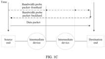
- the source end may send a bandwidth probe packet (namely, a bandwidth probe packet-fronthaul) to the destination end, and the bandwidth probe packet may be encapsulated by using a minimum Ethernet frame of 64 bytes, and may include TCP/IP header information, a fronthaul flag bit, a backhaul flag bit, or the like.
- a bandwidth probe packet namely, a bandwidth probe packet-fronthaul
- an egress port of an intermediate device in each hop may be used to limit a rate of a probe packet based on a bandwidth proportion (for example, 5%), and discard a probe packet that exceeds a port capability.
- the destination end may exchange a source address and a destination address of the received bandwidth probe packet and transmit the bandwidth probe packet (namely, a bandwidth probe packet-backhaul) back to the source end, and the rate of the bandwidth probe packet may not be limited in a return trip.
- the source end may send a data packet based on the rate of the bandwidth probe packet that is transmitted back, for example, the source end may immediately send a corresponding data packet each time one probe packet is received. It is assumed that a bandwidth proportion of the probe channel to the data channel is 1:19, in step 2, a process of transmitting the data packet and the bandwidth probe packet through the egress port of the intermediate device may be shown in FIG. 1D .
- a rate at which the source end sends the bandwidth probe packet is 1 Gbit/s
- a packet loss rate of 50% occurs due to a limitation of a probe queue
- an appropriate rate of the bandwidth probe packet should be 0.5 Gbit/s.
- the bandwidth proportion of the probe channel to the data channel is 1:19, it may be further determined that an appropriate data packet rate is 9.5 Gbit/s.
- FIG. 2 is a flowchart of claimed embodiments, of a load balancing method according to the present invention. As shown in FIG. 2 , the method according to this embodiment includes the following steps.
- Step 201 A source end determines, based on load statuses of respective probe channels on n paths between the source end and a destination end, a target path with a lightest load in the n paths.
- the probe channel is used to transmit a probe packet
- the probe packet includes a bandwidth probe packet
- n is an integer greater than 1.
- the load status may be used to indicate a load size, a load degree, or the like of the probe channel.
- transmission channels are classified into a probe channel and a data channel, and a data packet rate on the data channel is adjusted based on a packet loss rate of the bandwidth probe packet limited by the probe channel
- the target path with the lightest load in the n paths may be determined based on the load statuses of the respective probe channels of the n paths, and both a probe channel and a data channel on the target path have lightest loads.
- n paths may be specifically all or some paths between the source end and the destination end. This is not limited in this application.
- the source end may determine the load status of the probe channel based on the packet loss rate or a round trip time (Round Trip Time, RTT) of the bandwidth probe packet transmitted on the probe channel.
- RTT Round Trip Time
- the probe packet may further include a load probe packet.
- the load status of the probe channel may be determined by transmitting the load probe packet on the probe channel. Therefore, further, before step 201, the following step 2011 to step 2013 may be included.
- Step 2011 The source end sends a load probe packet to the destination end through a probe channel on each of the n paths.
- step 2011 may specifically include: sending, by the source end, the load probe packet to an intermediate device on the path through a probe channel on the path, and the intermediate device on the path forwards the load probe packet to the destination end.
- the load probe packet may be sent to the destination end through the probe channel on each path in a polling manner. This is not limited in this application.
- a specific description of forwarding the load probe packet by the intermediate device may be, for example, shown in FIG. 3A or FIG. 3B .
- the bandwidth probe packet a may be specifically a probe packet that is transmitted earlier than the load probe packet b.
- the intermediate device may forward the load probe packet to the destination end through the probe channel based on a queuing policy.
- the intermediate device may, for example, perform the following operations: if a packet is stacked in a probe queue but the probe queue is not full, putting the load probe packet b into the probe queue in a first-in-first-out order for sending; if the probe queue is full, discarding the load probe packet b; and if no packet is stacked in the probe queue, forwarding the load probe packet b.
- the load status of the probe channel may be represented based on the RTT of the load probe packet.
- the intermediate device may forward the load probe packet to the destination end through the probe channel based on a highest priority policy.
- the intermediate device may, for example, perform the following operations: (1) determining a packet stacking status of a probe queue of the probe channel, and if the stacking status of the probe queue of the probe channel reaches a preset degree (for example, stacking occurs), setting an ECN position in a packet header of the load probe packet b to 1; or if the stacking status of the probe queue of the probe channel does not reach a preset degree (for example, no stacking occurs), setting an explicit congestion notification (Explicit Congestion Notification, ECN) position of the load probe packet b to 0; (2) forwarding the load probe packet b with an updated packet header at a highest priority.
- ECN explicit Congestion Notification
- the load status of the probe channel may be represented based on an ECN identifier of the load probe packet. It should be noted that, if the stacking status of the probe queue in the probe channel does not reach the preset degree, the received load probe packet b may also be directly forwarded at the highest priority.
- the source end may send the load probe packet to the destination end through the probe channel on each of the n paths in a source routing manner. Specifically, for one of the n paths, the source end needs to calculate all intermediate devices through which the path passes, and add routing information of the path to a packet header of the load probe packet, so that the intermediate devices can perform routing based on the routing information, and the source end can send the load probe packet to the destination end through a probe channel on the path. It can be learned that, implementation of the source routing manner is complex.
- the n paths are in one-to-one correspondence with n path identifiers
- the path identifier is used by the intermediate device to perform routing by using a Hash algorithm
- the load probe packet that is sent to the destination end through the probe channel on each path includes a path identifier corresponding to a path.
- the intermediate device forwards the load probe packet to the destination end through the probe channel may specifically include: forwarding the load probe packet to the destination end through the probe channel based on the path identifier by using the Hash algorithm.
- a Hash function input of a conventional routing algorithm may be extended, based on a conventional Hash function calculated based on a 5-tuple (a source IP address, a destination IP address, a source port, a destination port, and a transport layer protocol), a new input parameter (namely, a path identifier, for example, a time to live (Time To Live, TTL)) is introduced, and mapping of an egress port is performed based on six parameters. Results obtained by using different path identifiers as input parameters of the Hash function are different, and mapped egress ports are different. Therefore, the n path identifiers may be used to distinguish between the n paths.
- a path identifier for example, using a shortest path (Equal Cost Multi path Routing, ECMP) algorithm to a maximum extent
- ECMP Equal Cost Multi path Routing
- Step 2012 The destination end returns the load probe packet received through the probe channel on each path to the source end.
- step 2012 may specifically include: returning, by the destination end, the load probe packet received through the path to the intermediate device, and forwarding, by the intermediate device, the load probe packet to the source end.
- the destination end may return, to the source end through the original path, the load probe packet received through the probe channel on each path, or may return the load probe packet to the source end through another path. This is not limited in this application.
- the destination end may exchange a source address and a destination address of the load probe packet, and then return the load probe packet to the source end.
- the intermediate device may not limit a rate of the returned load probe packet.
- the intermediate device may forward the load probe packet returned by the destination end to the source end based on the highest priority policy.
- Step 2013 The source end determines, based on the load probe packet returned on each path, a load status of the probe channel on each path.
- the load probe packet may be used to probe a load status.
- step 2013 may specifically include: using a round trip time RTT of the load probe packet returned on each path as load status information of the probe channel on each path. Specifically, a greater RTT of the load probe packet returned on the path may indicate a heavier load of the path, and a smaller RTT of the load probe packet returned on the path may indicate a lighter load of the path.
- step 2013 may specifically include: using an explicit congestion notification ECN identifier of the load probe packet returned on each path as load status information of the probe channel on each path. Specifically, when the ECN identifier of the load probe packet returned on the path is 1, it may indicate that a load of the path is relatively heavy; and when the ECN identifier of the load probe packet returned on the path is 0, it may indicate that the load of the path is relatively light.
- a method of using the RTT of the load probe packet returned on each path as the load status information of the probe channel on each path has a good effect.
- a buffer of the probe channel is relatively small (for example, only two probe packets are buffered)
- an RTT difference of transmitting the load probe packet through the probe channel is not obvious, and a load of the probe channel obtained by using a delay-based probe method may be inaccurate.
- a method of using the ECN of the load probe packet returned on each path as the load status information of the probe channel on each path may be used. This method can eliminate a negative impact caused by a delay-based probe error on determining a path load status.
- this method can determine the path load status more accurately, but a result is less accurate than obtained by the delay-based load probe method.
- the load statuses of the respective probe channels on the n paths may be periodically updated within first preset duration.
- step 2011 to step 2013 may be periodically performed within the first preset duration.
- the first preset duration may be greater than or equal to the RTT.
- n may be equal to a total quantity of paths between the source end and the destination end.
- the source end sends the load probe packet to the destination end through the probe channel on each of all paths between the source end and the destination end.
- the source end may determine the target path based on a global path load status.
- n may be less than a total quantity of paths between the source end and the destination end.
- the source end sends the load probe packet to the destination end through the probe channel on each of some paths between the source end and the destination end.
- the source end may determine the target path based on a local path load status. Compared with determining the target path based on the global path load status, determining the target path based on the local path load status can reduce overheads of polling and information storage.
- n path identifiers may include randomly determined m path identifiers, and path identifiers respectively corresponding to d paths in all paths used to determine the target path (for example, a target path determined last time), where n is greater than or equal to m and is less than or equal to m + d, and loads of the d paths are less than or equal to a load of another path in all the paths.
- the n path identifiers are in one-to-one correspondence with the n paths, the n path identifiers should be different from each other.
- the randomly determined m path identifiers may include all or some of the d path identifiers respectively corresponding to the d paths, or may not include the d path identifiers, n may be greater than or equal to m and is less than or equal to m + d.
- the previously determined target path may be specifically a target path determined last time, and correspondingly, the d paths in all the paths used to determine the target path previously may be understood as a local optimal solution of a previous round.
- Hashi_metric may represent a load status of a path i, and a smaller value may indicate a lighter load; and TTLi may indicate a path identifier of the path i, where i may be equal to 1, 2, 3, ....
- n may be equal to 2.
- d may be equal to 1.
- convergence of the target path obtained through the local optimal solution (to be specific, the target path obtained through the local optimal solution may tend to be consistent with the target path determined based on the global path load status) can be theoretically proved with reference to a queuing theory model and a Lyapunov drift function.
- a transmission process of a packet on a path may be abstracted as a queuing network model shown in FIG. 5 .
- An egress port buffer of each intermediate device may be abstracted as a sub-queue.
- a process in which one packet is sent from a source end, passes through intermediate devices at multiple hops, and arrives at a destination end may be abstracted as a multi-queue serial queuing model.
- a quadratic Lyapunov function V is constructed, and stability of an algorithm is demonstrated by proving that the Lyapunov function has a negatively expected single-step drift.
- each queue can output a maximum of one data unit at a same moment. Therefore, the following formula is obtained: q * t ⁇ q * t + 1 ⁇ 1
- Formula (3) is also as follows: q ⁇ i t + 1 ⁇ q * t + 1 ⁇ q ⁇ i t ⁇ q * t + K + 1
- the upper bound of the first term of the Lyapunov function is as follows: E V 1 t + 1 ⁇ V 1 t
- the Lyapunov function has a step of negatively expected drift.
- the (1, 1) policy is converged to a JSQ policy of the global optimal solution, and this is contradictory to the hypothesis. Therefore, the value of V 1 (t) cannot be very large.
- V 2 (t) If the value of V 2 (t) is very large, it indicates that there definitely exists a value t 2 , and when t ⁇ t 2 , loads of a full queue are heavy, and a value of q i ( t ) is very large and keeps increasing. It is assumed that the value of a global optimal solution q ⁇ ( t ) is not large in this case, in other words, a difference between values of q ⁇ ( t ) and q i ( t ) is very large.
- the Lyapunov function has a step of negatively expected drift.
- the (1, 1) policy is converged to the global optimal solution, and this is contradictory to the hypothesis. Therefore, the value of V 2 (t) cannot be very large.
- the Lyapunov function has a step of negatively expected drift.
- the (1, 1) policy is converged to the global optimal solution, and this is contradictory to the hypothesis. Therefore, the value of V 2 (t) cannot be very large.
- a three-layer DCN architecture shown in FIG. 5 is constructed on a simulation platform OMNET+ (Objective Modular Network Testbed in C++), and convergence of the solution of the present invention is verified by analyzing a data transmission effect in the network architecture.
- each end node for example, a server
- a destination address of the data flow is random
- a size of a data packet complies with heavy-tailed distribution.
- FIG. 6 in this embodiment of this application, when the target path is determined through the local optimal solution, a maximum difference between lengths of output queues of ports at any moment does not exceed a difference between N1 and N2. It can be learned that load balancing can be implemented by using the target path determined through the local optimal solution.
- the target path may be determined once by performing step 201.
- the method may further include the following step:
- the source end determines whether the to-be-transmitted data packet and a transmitted data packet belong to a same scheduling unit.
- the source end performs step 201.
- a target path of the transmitted data packet is used as a target path of the to-be-transmitted data packet.
- the determining whether the to-be-transmitted data packet and a transmitted data packet belong to a same scheduling unit includes: determining whether the to-be-transmitted data packet and a transmitted data packet that is transmitted within second preset duration belong to a same scheduling unit.
- the scheduling unit includes a data packet, a flow, or a set of a plurality of data packets in a same flow.
- the first preset duration may be less than or equal to the second preset duration.
- Step 202 The source end sends the bandwidth probe packet to the destination end through the probe channel on the target path.
- a packet header of the bandwidth probe packet may include a path identifier corresponding to the target path, so that the intermediate device forwards the bandwidth probe packet to the destination end through the probe channel on the target path based on the path identifier.
- Step 203 The destination end returns the bandwidth probe packet to the source end.
- Step 204 The source end sends, based on the bandwidth probe packet returned by the destination end, the to-be-transmitted data packet to the destination end through a data channel on the target path.
- a packet header of the to-be-transmitted data packet may include a path identifier corresponding to the target path, so that the intermediate device forwards the to-be-transmitted data packet to the destination end through the probe channel on the target path based on the path identifier.
- an objective of step 202 to step 204 is to adjust a data packet rate on the data channel based on a packet loss rate of the bandwidth probe packet limited by the probe channel on the target path, and the like.
- a specific manner of adjusting the data packet rate on the data channel based on the packet loss rate of the bandwidth probe packet limited by the probe channel on the target path, and the like is not limited in this embodiment of this application.
- the source end determines, based on the load statuses of the respective probe channels on the n paths between the source end and the destination end, the target path with the lightest load in the n paths, and sends the bandwidth probe packet to the destination end through the probe channel on the target path; the destination end returns the bandwidth probe packet to the source end; and the source end sends the to-be-transmitted data packet to the destination end through the data channel on the target path based on the bandwidth probe packet returned by the destination end. Therefore, the target path with the lightest load is selected based on the load statuses of the respective probe channels on the n paths, thereby implementing load balancing among a plurality of paths.
- FIG. 7 is a flowchart of an unclaimed, Embodiment 2 of a load balancing method according to an embodiment of this application.
- a scheduling unit is a flow and a path identifier is a TTL is used for the following description.
- the method according to this embodiment may include the following steps.
- Step 701 When a to-be-transmitted data packet needs to be sent to a destination end, a source end queries whether a flow table of the source end includes a valid path of a data flow to which the to-be-transmitted data packet belongs.
- the flow table when the flow table includes a correspondence between an identifier of the data flow to which the to-be-transmitted data packet belongs and a forwarding path, and a valid status is valid, it may be determined that the flow table includes the valid path of the data flow to which the to-be-transmitted data packet belongs.
- the flow table includes the correspondence between the identifier of the data flow to which the to-be-transmitted data packet belongs and the forwarding path, but the valid status is invalid, or when the flow table does not include a correspondence between the identifier of the data flow to which the to-be-transmitted data packet belongs and an identifier of the target path, it may be determined that the flow table does not include the valid path of the data flow to which the to-be-transmitted data packet belongs.
- a table entry of the flow table of the source end may record a flow identifier (Flow ID), a forwarding path, an aging bit, and a valid bit.
- Flow ID flow identifier
- a forwarding path identifier for forwarding
- an aging bit identifier for forwarding
- a valid bit When the valid bit is set to true, it may be considered that the valid status is valid; and when the valid bit is set to false, it may be considered that the valid status is invalid.
- valid duration of information in the flow table may be limited to second preset duration.
- the flow table may be periodically updated based on the second preset duration.
- the following flow table information update operation may be performed by using the second preset duration as a period:
- a validity period of each data flow in the flow table is the second preset duration, and a corresponding data packet that arrives within the validity period is scheduled based on a forwarding path in the flow table.
- step 702 When the flow table of the source end does not include the valid path of the data flow to which the to-be-transmitted data packet belongs, the following step 702 is performed.
- step 708 When the flow table of the source end includes the valid path of the data flow to which the to-be-transmitted data packet belongs, the following step 708 is performed.
- Step 702 The source end randomly selects m TTL values to mark m paths to the destination end, and records the m paths as a candidate path set.
- Step 703 The source end adds, to the candidate path set, d optimal paths that are obtained when determining the target path last time.
- a path status table may record a destination end identifier (DestID) such as a destination end address; a TTL value of a path such as a TTL value of a path 1 Hashl_index, a TTL value of a path 2 Hash2_index, and a TTL value of a path 3 Hash3_index; and a load status of the path such as a load status of the path 1 Hash1_metric, a load status of the path 2 Hash2_metric, and a load status of the path 3 Hash3_metric.
- the d paths may be determined based on the path status table.
- the path status table may be periodically updated by using first preset duration as a period.
- step 702 to step 704 may be performed to update the path status table.
- the candidate path set herein may be understood as a path set formed by the foregoing n paths.
- Step 704 The source end probes a load status of each path in the candidate path set.
- the load status of each path in the candidate path set may be probed by performing step 2011 to step 2013.
- the path status table may be updated based on the load status of each path.
- Step 705 The source end determines a target path with a lightest load based on the load status of each path.
- Step 706 The source end sends a bandwidth probe packet to the destination end through a probe channel on the target path, receives the bandwidth probe packet returned by the destination end, and sends a to-be-transmitted data packet to the destination end through a data channel on the target path based on the received bandwidth probe packet returned by the destination end.
- the to-be-transmitted data packet may be sent to the destination end through the data channel on the target path by performing step 202 to step 204.
- Step 707 The source end updates the flow table by using the target path as a forwarding path of the data flow to which the to-be-transmitted data packet belongs.
- the correspondence between the identifier of the data flow to which the to-be-transmitted data packet belongs and the target path may be updated to the flow table, and a valid status is set to valid. It should be noted that, for the flow table shown in FIG. 8A , after it is determined that step 702 needs to be performed, the value of the valid bit may be changed to true.
- step 707 and step 706 are not limited.
- Step 708 The source end sends a bandwidth probe packet to the destination end through a probe channel on the valid path of the data flow to which the to-be-transmitted data packet belongs in the flow table, receives the bandwidth probe packet returned by the destination end, and sends, based on the bandwidth probe packet returned by the destination end, the to-be-transmitted data packet to the destination end through a data channel on the valid path.
- step 708 is similar to step 706, and details are not described herein.
- step 708 after it is determined that step 708 needs to be performed, the value of the valid bit may be changed to false.
- the source end queries whether the flow table of the source end includes the valid path of the data flow to which the to-be-transmitted data packet belongs. If the flow table of the source end includes the valid path of the data flow to which the to-be-transmitted data packet belongs, the source end sends the to-be-transmitted data packet to the destination end through the data channel on the valid path of the data flow to which the to-be-transmitted data packet belongs in the flow table. Otherwise, the source end determines the target path with the lightest load based on load statuses of respective probe channels on the n paths, and sends the to-be-transmitted data packet to the destination end through the data channel on the target path. Therefore, with the flow as the scheduling unit, the target path with the lightest load is selected based on the load statuses of the respective probe channels on the n paths, thereby implementing load balancing among a plurality of paths.
- FIG. 9 is a schematic structural diagram of a source end according to an embodiment of this application.
- the source end in this embodiment may include a path determining unit 901, a bandwidth probe packet transceiver unit 902, and a data packet transmitting unit 903.
- the path determining unit 901 is configured to determine, based on load statuses of respective probe channels on n paths between the source end and a destination end, a target path with a lightest load in the n paths, where the probe channel is used to transmit a probe packet, the probe packet includes a bandwidth probe packet, and n is an integer greater than 1.
- the bandwidth probe packet transceiver unit 902 is configured to send a bandwidth probe packet to the destination end through a probe channel on the target path, and receive the bandwidth probe packet returned by the destination end.
- the data packet transmitting unit 903 is configured to send, based on the bandwidth probe packet returned by the destination end, a to-be-transmitted data packet to the destination end through a data channel on the target path.
- the probe packet further includes a load probe packet; and the source end further includes a load probe packet determining unit 904, configured to:
- the load probe packet determining unit 904 is configured to determine, based on the load probe packet returned on each path, a load status of the probe channel on each path specifically includes: using a round trip time RTT or an explicit congestion notification ECN identifier of the load probe packet returned on each path as load status information of the probe channel on each path.
- the load probe packet determining unit 904 is specifically configured to periodically perform the following steps within first preset duration: sending the load probe packet to the destination end through the probe channel on each of the n paths, and receiving the load probe packet returned by the destination end; and determining, based on the load probe packet returned on each path, the load status of the probe channel on each path.
- the n paths are in one-to-one correspondence with n path identifiers, and the path identifier is used by an intermediate device to perform routing by using a Hash algorithm; and the load probe packet that is sent to the destination end through the probe channel on each path includes a path identifier corresponding to a path, where a packet header of the bandwidth probe packet and a packet header of the data packet all include a path identifier corresponding to the target path.
- n is less than a total quantity of paths between the source end and the destination end
- the n path identifiers include randomly determined m path identifiers, and path identifiers respectively corresponding to d paths in all paths used to determine the target path previously, where n is greater than or equal to m and is less than or equal to m + d, and loads of the d paths are less than or equal to a load of another path in all the paths.
- n is equal to 2.
- the source end further includes a judging unit 905, configured to determine whether the to-be-transmitted data packet and a transmitted data packet belong to a same scheduling unit.
- the path determining unit 901 is specifically configured to: when the to-be-transmitted data packet and the transmitted data packet do not belong to the same scheduling unit, determine the target path in the n paths based on the load statuses of the respective probe channels on the n paths between the source end and the destination end.
- the path determining unit 901 is further configured to: when the to-be-transmitted data packet and the transmitted data packet belong to the same scheduling unit, use a target path of the transmitted data packet as a target path of the to-be-transmitted data packet.
- the judging module 905 is specifically configured to determine whether the to-be-transmitted data packet and a transmitted data packet that is transmitted within second preset duration belong to a same scheduling unit.
- the scheduling unit includes a data packet, a flow, or a set of a plurality of data packets in a same flow.
- the source end in this embodiment may be configured to execute the technical solution of a source end side according to the embodiments shown in FIG. 2 and FIG. 7 , implementation principles and technical effects thereof are similar to those in the embodiments shown in FIG. 2 and FIG. 7 , and details are not described herein.
- FIG. 10 is a schematic structural diagram of a destination end according to an embodiment of this application.
- the destination end in this embodiment may include a bandwidth probe packet transceiver unit 1001 and a data packet receiving unit 1002.
- the bandwidth probe packet transceiver unit 1001 is configured to receive a bandwidth probe packet sent by a source end through a probe channel on a target path, where the target path is a path with a lightest load in n paths that is determined by the source end based on load statuses of respective probe channels on the n paths between the source end and the destination end, the probe channel is used to transmit a probe packet, the probe packet includes the bandwidth probe packet, and n is an integer greater than 1.
- the bandwidth probe packet transceiver unit 1001 is further configured to return the bandwidth probe packet to the source end.
- the data packet receiving unit 1002 is configured to receive a data packet sent by the source end through a data channel on the target path.
- the probe packet further includes a load probe packet; and the destination end further includes a load probe packet transceiver unit 1003, configured to:
- the n paths are in one-to-one correspondence with n path identifiers, and the path identifier is used by an intermediate device to perform routing by using a Hash algorithm; and a packet header of the load probe packet that is sent to the destination end through the probe channel on each path includes a path identifier corresponding to a path, where a packet header of the bandwidth probe packet and a packet header of the data packet all include a path identifier corresponding to the target path.
- n is less than a total quantity of paths between the source end and the destination end
- the n path identifiers include randomly determined m path identifiers, and path identifiers respectively corresponding to d paths in all paths used to determine the target path previously, where n is greater than or equal to m and is less than or equal to m + d, and loads of the d paths are less than or equal to a load of another path in all the paths.
- n is equal to 2.
- the destination end in this embodiment may be configured to execute the technical solution of a destination end side according to the embodiments shown in FIG. 2 and FIG. 7 , implementation principles and technical effects thereof are similar to those in the embodiments shown in FIG. 2 and FIG. 7 , and details are not described herein.
- FIG. 11 is a schematic structural diagram of an intermediate device according to an embodiment of this application.
- the intermediate device in this embodiment may include a first receiving unit 1101, a first forwarding unit 1102, a second receiving unit 1103, and a second forwarding unit 1104.
- the first receiving unit 1101 is configured to receive a load probe packet sent by a source end
- the first forwarding unit 1102 is configured to forward the load probe packet to a destination end through a probe channel, where the probe channel is used to transmit a probe packet, and the probe packet includes the load probe packet.
- the second receiving unit 1103 is configured to receive the load probe packet returned by the destination end.
- the second forwarding unit 1104 is configured to forward the load probe packet returned by the destination end to the source end.
- the first forwarding unit 1102 is specifically configured to: forward the load probe packet to the destination end through the probe channel based on a queuing policy.
- the first forwarding unit 1102 is specifically configured to: forward the load probe packet to the destination end through the probe channel based on a highest priority policy.
- the second forwarding unit 1104 is specifically configured to: forward the load probe packet returned by the destination end to the source end based on the highest priority policy.
- a packet header of the load probe packet includes a path identifier; and that the first forwarding unit 1102 is configured to forward the load probe packet to a destination end through a probe channel specifically includes: forwarding the load probe packet to the destination end through the probe channel based on the path identifier by using a Hash algorithm.
- the intermediate device in this embodiment may be configured to execute the technical solution of an intermediate device side according to the embodiments shown in FIG. 2 and FIG. 7 , implementation principles and technical effects thereof are similar to those in the embodiments shown in FIG. 2 and FIG. 7 , and details are not described herein.
- division of the units of the foregoing communications devices is merely logical function division, and during actual implementation, the units may be all or partially integrated into a physical entity, or may be physically separated.
- all of the units may be implemented in a form of software invoked by a processing element or in a form of hardware.
- some of the units may be implemented in a form of software invoked by a processing element, and some of the units may be implemented in a form of hardware.
- a transmitting unit may be an independently disposed processing element, or may be integrated into a chip of a network device for implementation.
- the transmitting unit may be alternatively stored in a memory of a network device in a form of a program, and a processing element of the network device invokes and executes a function of the transmitting unit. Implementation of the other units is similar to that of the transmitting unit. In addition, all or some of the units may be integrated together, or may be implemented independently.
- the processing element herein may be an integrated circuit with a signal processing capability. In an implementation process, steps in the foregoing methods or the foregoing units can be implemented by using a hardware integrated logical circuit in the processing element, or by using instructions in a form of software.
- the transmitting unit is a transmitting control unit, and may receive information by using a transmitting apparatus of the network device such as an antenna and a radio frequency apparatus.
- the foregoing units may be configured as one or more integrated circuits for implementing the foregoing method, for example, one or more application-specific integrated circuits (Application Specific Integrated Circuit, ASIC), one or more microprocessors (digital signal processor, DSP), or one or more field programmable gate arrays (Field Programmable Gate Array, FPGA).
- ASIC Application Specific Integrated Circuit
- DSP digital signal processor
- FPGA Field Programmable Gate Array
- the processing element may be a general-purpose processor, for example, a central processing unit (Central Processing Unit, CPU) or another processor that can invoke the program.
- the units may be integrated together, and implemented in a form of a system on chip (system-on-a-chip, SOC).
- FIG. 12 is a schematic diagram of a hardware structure of a communications device according to an embodiment of this application.
- the communications device 120 includes at least one processor 1201, a communications bus 1202, a memory 1203, and at least one communications interface 1204.
- the processor 1201 may be a central processing unit (central processing unit, CPU), a microprocessor, an application-specific integrated circuit (application-specific integrated circuit, ASIC), or one or more integrated circuits configured to control program execution in the solutions of this application.
- CPU central processing unit
- ASIC application-specific integrated circuit
- the communications bus 1202 may include a channel, to transfer information between the foregoing components.
- the communications interface 1204 uses any apparatus such as a transceiver to communicate with another device or a communications network, such as the Ethernet, a radio access network (radio access network, RAN), or a wireless local area network (wireless local area networks, WLAN).
- a transceiver to communicate with another device or a communications network, such as the Ethernet, a radio access network (radio access network, RAN), or a wireless local area network (wireless local area networks, WLAN).
- RAN radio access network
- WLAN wireless local area network
- the memory 1203 may be a read-only memory (read-only memory, ROM), another type of static storage device that can store static information and instructions, a random access memory (random access memory, RAM), or another type of dynamic storage device that can store information and instructions; or may be an electrically erasable programmable read-only memory (electrically erasable programmable read-only memory, EEPROM), a compact disc read-only memory (compact disc read-only memory, CD-ROM) or another optical disk storage, an optical disc storage (including a compact optical disc, a laser disc, an optical disc, a digital versatile disc, a Blu-ray disc, or the like), a magnetic disk storage medium or another magnetic storage device, or any other medium capable of carrying or storing expected program code in a form of instructions or data structures and capable of being accessed by a computer, but is not limited thereto.
- the memory may exist independently, and is connected to the processor by using a bus.
- the memory may be alternatively integrated with the processor.
- the memory 1203 is configured to store application program code for executing the solution of this application, and the processor 1201 controls the execution.
- the processor 1201 is configured to execute the application program code stored in the memory 1203, to implement the load balancing method according to the foregoing embodiments of this application.
- the processor 1201 may perform processing-related functions in the load balancing method provided in the foregoing embodiments, and the communications interface 1204 is responsible for communicating with another device or a communications network. This is not specifically limited in this embodiment of this application.
- the processor 1201 may include one or more CPUs.
- the communications device 120 may include a plurality of processors.
- Each of the processors may be a single-core processor (single-CPU), or may be a multicore processor (multi-CPU).
- the processors herein may be one or more devices, circuits, and/or processing cores for processing data (for example, computer program instructions).
- the communications device 120 may further include an output device and an input device.
- the output device communicates with the processor 1201, and may display information in a plurality of manners.
- the output device may be a liquid crystal display (liquid crystal display, LCD), a light emitting diode (light emitting diode, LED) display device, a cathode ray tube (cathode ray tube, CRT) display device, a projector (projector), or the like.
- the input device communicates with the processor 1201, and may receive input of a user in a plurality of manners.
- the input device may be a mouse, a keyboard, a touchscreen device, a sensor device, or the like.
- the communications device 120 may be a chip, or a source end, or a destination end, or an intermediate device, or a device having a structure similar to that in FIG. 12 .
- a type of the communications device 120 is not limited in this embodiment of this application.
- the communications device 120 is presented with the function modules implemented through integration.
- the "module" herein may be an application-specific integrated circuit (Application-Specific Integrated Circuit, ASIC), a circuit, a processor and a memory that execute one or more software programs or firmware programs, an integrated logic circuit, and/or another device that can provide the foregoing function.
- ASIC Application-Specific Integrated Circuit
- the communications device 120 may use the form shown in FIG. 12 .
- the function/implementation process of the units in FIG. 9 to FIG. 11 may be implemented by the processor 1201 and the memory 1203 in FIG. 12 .
- the bandwidth probe packet transceiver unit in FIG. 9 may be implemented by using the communications interface 1204 in FIG. 12 , and this is not limited in this embodiment of this application.
- the communications device may be specifically the source end in the embodiment shown in FIG. 2 or FIG. 7 .
- the processor 1201 invokes the program stored in the memory 1203, the method on the source end side according to the embodiment shown in FIG. 2 or FIG. 7 may be performed.
- the communications device may be specifically the destination end in the embodiment shown in FIG. 2 or FIG. 7 .
- the processor 1201 invokes the program stored in the memory 1203, the method on the destination end side according to the embodiment shown in FIG. 2 or FIG. 7 may be performed.
- the communications device may be specifically the intermediate device in the embodiment shown in FIG. 2 or FIG. 7 .
- the processor 1201 invokes the program stored in the memory 1203, the method on the intermediate device side according to the embodiment shown in FIG. 2 or FIG. 7 may be performed.
- an embodiment of this application provides a communications system.
- the communications system may include the source end, the destination end, and the intermediate device in any one of the foregoing embodiments.
- All or some of the foregoing embodiments may be implemented by using software, hardware, firmware, or any combination thereof.
- a software program is used to implement the embodiments, the embodiments may be implemented completely or partially in a form of a computer program product.
- the computer program product includes one or more computer instructions.
- the computer program instructions When the computer program instructions are loaded and executed on a computer, the procedure or functions according to the embodiments of this application are all or partially generated.
- the computer may be a general-purpose computer, a dedicated computer, a computer network, or another programmable apparatus.
- the computer instructions may be stored in a computer readable storage medium or may be transmitted from a computer readable storage medium to another computer readable storage medium.
- the computer instructions may be transmitted from a website, computer, server, or data center to another website, computer, server, or data center in a wired (for example, a coaxial cable, an optical fiber, or a digital subscriber line (Digital Subscriber Line, DSL)) or wireless (for example, infrared, radio, or microwave) manner.
- the computer readable storage medium may be any usable medium accessible by a computer, or a data storage device, such as a server or a data center, integrating one or more usable media.
- the usable medium may be a magnetic medium (for example, a floppy disk, a hard disk, or a magnetic tape), an optical medium (for example, a DVD), a semiconductor medium (for example, a solid-state drive (Solid State Disk, SSD)), or the like.
- a magnetic medium for example, a floppy disk, a hard disk, or a magnetic tape
- an optical medium for example, a DVD
- a semiconductor medium for example, a solid-state drive (Solid State Disk, SSD)
Landscapes
- Engineering & Computer Science (AREA)
- Computer Networks & Wireless Communication (AREA)
- Signal Processing (AREA)
- Health & Medical Sciences (AREA)
- Cardiology (AREA)
- General Health & Medical Sciences (AREA)
- Data Exchanges In Wide-Area Networks (AREA)
Description
- This application claims priority to
Chinese Patent Application No. 201810333794.1, filed with the Chinese Patent Office on April 13, 2018 - This application relates to the field of communications technologies, and in particular, to a load balancing method.
- To prevent congestion such as data packet stacking and packet loss, congestion control is needed for data packet transmission.
- In the prior art, in a congestion control method, transmission channels between a source end and a destination end are classified into a data channel and a probe channel based on a proportion. Specifically, the source end first sends a bandwidth probe packet (for example, a Credit probe packet) to the destination end through the probe channel, and the bandwidth probe packet is sent to the destination end by using a router, and is returned by the destination end to the source end. Then, the source end may detect an available bandwidth of the data channel from the source end to the destination end based on a packet loss rate of the bandwidth probe packet limited by the router, and send a data packet to the destination end based on the perceived available bandwidth of the data channel, thereby implementing congestion control on the data packet. In addition, in the congestion control method, the data packet is seldom stacked, and a round trip time (round trip time, RTT) of the data packet is basically fixed. Therefore, when there are a plurality of paths between the source end and the destination end, load balancing of the plurality of paths cannot be implemented based on the RTT.
US2017/295100A1 describes example methods for a source virtual tunnel endpoint (VTEP) to perform congestion-aware load balancing in a data center network. It is described that the method may comprise the source VTEP learning congestion state information associated with multiple paths provided by respective multiple intermediate switches connecting the source VTEP with a destination VTEP. It is described that the method may also comprise the source VTEP receiving second packets that are sent by a source endpoint and destined for a destination endpoint; and selecting a particular path from multiple paths based on the congestion state information. It is described that the method may further comprise the source VTEP generating encapsulated second packets by encapsulating each of the second packets with header information that includes a set of tuples associated with the particular path; and sending the encapsulated second packets to the destination endpoint.
CN107786440A describes a data message forwarding method and apparatus. The method comprises the following steps: collecting, by a source switch, the congestion degrees of d samplingpaths in n paths according to a preset sampling period, and storing the congestion degree indication information of each sampling path, wherein d is smaller than n; selecting a first target samplingpath with the minimum congestion degree within a first time according to the congestion degree indication information, and forwarding a first data message via the first target sampling path, and storing an identifier of a first data flow cell to which the first data message belongs; if the identifier of a second data flow cell to which a second data message belongs is the same as the identifier ofthe first data flow cell, forwarding the second data message via the first target sampling path; or otherwise, selecting a second target sampling path with the minimum congestion degree within a second time, and forwarding the second data message via the second target sampling path. The data message forwarding method and apparatus disclosed by the embodiment of the invention have the advantages of improving the applicability of data forwarding and the extendibility of network congestion perception. - Therefore, how to implement the load balancing among the plurality of paths based on the congestion control method becomes an urgent problem to be resolved currently.
- This application provides a load balancing method, to implement load balancing among a plurality of paths.
- The invention are the scope of protection is defined in the appended independent claims, where embodiments are defined in the appended dependent claims.
- According to a first aspect, a claimed embodiment of the present invention provides a load balancing method performed by a source end, including:
- determining, based on load statuses of respective probe channels on n paths between a source end and a destination end, a target path with a lightest load in the n paths, where the probe channel is used to transmit a probe packet, the probe packet includes a bandwidth probe packet, and n is an integer greater than 1;
- sending a bandwidth probe packet to the destination end through a probe channel on the target path, and receiving the bandwidth probe packet returned by the destination end; and
- sending, based on the bandwidth probe packet returned by the destination end, a to-be-transmitted data packet to the destination end through a data channel on the target path.
- In the foregoing solution, the target path with the lightest load in the n paths is determined based on the load statuses of the respective probe channels on the n paths between the source end and the destination end, the bandwidth probe packet is sent to the destination end through the probe channel on the target path, the bandwidth probe packet returned by the destination end is received, and the to-be-transmitted data packet is sent to the destination end through the data channel on the target path based on the bandwidth probe packet returned by the destination end. Therefore, the target path with the lightest load is selected based on the load statuses of the respective probe channels on the n paths, thereby implementing load balancing among a plurality of paths.
- In this embodiment, the probe packet further includes a load probe packet; and before the determining, based on load statuses of respective probe channels on n paths between a source end and a destination end, a target path with a lightest load in the n paths, the method further includes:
- sending a load probe packet to the destination end through a probe channel on each of the n paths, and receiving the load probe packet returned by the destination end; and
- determining, based on the load probe packet returned on each path, a load status of the probe channel on each path.
- In the foregoing solution, the load probe packet is sent to the destination end through the probe channel on each of the n paths, the load probe packet returned by the destination end is received, and the load status of the probe channel on each path is determined based on the load probe packet returned on each path. Therefore, the load status of the probe channel is determined.
- In an implementable design, the determining, based on the load probe packet returned on each path, a load status of the probe channel on each path includes: using a round trip time RTT or an explicit congestion notification ECN identifier of the load probe packet returned on each path as load status information of the probe channel on each path.
- In an implementable design, the following steps are periodically performed within first preset duration:
sending the load probe packet to the destination end through the probe channel on each of the n paths, and receiving the load probe packet returned by the destination end; and determining, based on the load probe packet returned on each path, the load status of the probe channel on each path. - In the foregoing solution, the load status of the probe channel is continuously updated by performing the following steps periodically within the first preset duration: sending the load probe packet to the destination end through the probe channel on each of the n paths, and receiving the load probe packet returned by the destination end; and determining, based on the load probe packet returned on each path, the load status of the probe channel on each path.
- In an unclaimed implementable design, the n paths are in one-to-one correspondence with n path identifiers, and the path identifier is used by an intermediate device to perform routing by using a Hash algorithm; and
the load probe packet that is sent to the destination end through the probe channel on each path includes a path identifier corresponding to a path, where a packet header of the bandwidth probe packet and a packet header of the data packet all include a path identifier corresponding to the target path. - In the foregoing solution, the load probe packet that is sent to the destination end through the probe channel on each path includes a path identifier corresponding to a path, where the packet header of the bandwidth probe packet and the packet header of the data packet all include the path identifier corresponding to the target path. This resolves a problem of complex implementation of a source routing manner.
- In an unclaimed implementable design, n is less than a total quantity of paths between the source end and the destination end, and the n path identifiers include randomly determined m path identifiers, and path identifiers respectively corresponding to d paths in all paths used to determine the target path previously, where n is greater than or equal to m and is less than or equal to m + d, and loads of the d paths are less than or equal to a load of another path in all the paths.
- In the foregoing solution, the n path identifiers include the randomly determined m path identifiers, and the path identifiers respectively corresponding to the d paths in all the paths used to determine the target path previously. Therefore, a local optimal solution is used to determine the target path. This ensures that the determined target path is consistent with a target path that is determined based on a global path load status, and also reduces overheads of polling and information storage compared to a solution of determining the target path based on the global path load status.
- In an unclaimed implementable design, m is equal to 2.
- In an implementable design, before the determining, based on load statuses of respective probe channels on n paths between a source end and a destination end, a target path with a lightest load in the n paths, the method further includes:
- determining whether the to-be-transmitted data packet and a transmitted data packet belong to a same scheduling unit; and
- when the to-be-transmitted data packet and the transmitted data packet do not belong to the same scheduling unit, performing the step of determining, based on load statuses of respective probe channels on n paths between a source end and a destination end, a target path with a lightest load in the n paths.
- In an implementable design, the method further includes:
when the to-be-transmitted data packet and the transmitted data packet belong to the same scheduling unit, using a target path of the transmitted data packet as a target path of the to-be-transmitted data packet. - In the foregoing solution, when the to-be-transmitted data packet and the transmitted data packet do not belong to the same scheduling unit, the target path with the lightest load in the n paths is determined based on the load statuses of the respective probe channels on the n paths between the source end and the destination end; and when the to-be-transmitted data packet and the transmitted data packet belong to the same scheduling unit, the target path of the transmitted data packet is used as the target path of the to-be-transmitted data packet. Therefore, data packets that belong to a same scheduling unit are transmitted on a same target path.
- In an implementable design, the determining whether the to-be-transmitted data packet and a transmitted data packet belong to a same scheduling unit includes:
determining whether the to-be-transmitted data packet and a transmitted data packet that is transmitted within second preset duration belong to a same scheduling unit. - In an implementable design, the scheduling unit includes a data packet, a flow, or a set of a plurality of data packets in a same flow.
- In the foregoing solution, the scheduling unit includes a data packet, a flow, or a set of a plurality of data packets in a same flow. Therefore, data packets in a same data packet, a same data flow, or a plurality of data packets in a same data flow are transmitted on a same target path.
- According to a second aspect, a claimed embodiment of the present invention provides a load balancing method performed by a destination end, including:
- receiving a bandwidth probe packet sent by a source end through a probe channel on a target path, where the target path is a path with a lightest load in n paths that is determined by the source end based on load statuses of respective probe channels on the n paths between the source end and a destination end, the probe channel is used to transmit a probe packet, the probe packet includes the bandwidth probe packet, and n is an integer greater than 1;
- returning the bandwidth probe packet to the source end; and
- receiving a data packet sent by the source end through a data channel on the target path.
- In the foregoing solution, the target path is the path with the lightest load in the n paths that is determined by the source end based on the load statuses of the respective probe channels on the n paths between the source end and the destination end. Therefore, the target path with the lightest load is selected based on the load statuses of the respective probe channels on the n paths, thereby implementing load balancing among a plurality of paths.
- In this embodiment, the probe packet further includes a load probe packet; and before the receiving a bandwidth probe packet sent by a source end through a probe channel on a target path, the method further includes:
- receiving a load probe packet sent by the source end through a probe channel on each of the n paths; and
- returning the load probe packet received through the probe channel on each path to the source end.
- In the foregoing solution, the load probe packet sent by the source end through the probe channel on each of the n paths is received, and the load probe packet received through the probe channel on each path is returned to the source end. Therefore, the source end can determine a load status of the probe channel on each path based on the load probe packet returned on each path, thereby determining the load status of the probe channel.
- In an unclaimed implementable design, the n paths are in one-to-one correspondence with n path identifiers, and the path identifier is used by an intermediate device to perform routing by using a Hash algorithm; and
a packet header of the load probe packet that is sent to the destination end through the probe channel on each path includes a path identifier corresponding to a path, where a packet header of the bandwidth probe packet and a packet header of the data packet all include a path identifier corresponding to the target path. - In the foregoing solution, the load probe packet that is sent to the destination end through the probe channel on each path includes a path identifier corresponding to a path, where the packet header of the bandwidth probe packet and the packet header of the data packet all include the path identifier corresponding to the target path. This resolves a problem of complex implementation of a source routing manner.
- In an unclaimed implementable design, n is less than a total quantity of paths between the source end and the destination end, and the n path identifiers include randomly determined m path identifiers, and path identifiers respectively corresponding to d paths in all paths used to determine the target path previously, where n is greater than or equal to m and is less than or equal to m + d, and loads of the d paths are less than or equal to a load of another path in all the paths.
- In the foregoing solution, the n path identifiers include the randomly determined m path identifiers, and the path identifiers respectively corresponding to the d paths in all the paths used to determine the target path previously. Therefore, a local optimal solution is used to determine the target path. This ensures that the determined target path is consistent with a target path that is determined based on a global path load status, and also reduces overheads of polling and information storage compared to a solution of determining the target path based on the global path load status.
- In an unclaimed implementable design, m is equal to 2.
- According to a third aspect, an unclaimed embodiment of this application provides a load balancing method, including:
- receiving a load probe packet sent by a source end;
- forwarding the load probe packet to a destination end through a probe channel, where the probe channel is used to transmit a probe packet, and the probe packet includes the load probe packet;
- receiving the load probe packet returned by the destination end; and
- forwarding the load probe packet returned by the destination end to the source end.
- In the foregoing solution, the load probe packet sent by the source end is received, the load probe packet is forwarded to the destination end through the probe channel, the load probe packet returned by the destination end is received, and the load probe packet returned by the destination end is forwarded to the source end. Therefore, an intermediate device can forward the load probe packet that is sent through the probe channel between the source end and the destination end, and the source end can determine a load status of the probe channel based on the load probe packet.
- In an implementable design, the forwarding the load probe packet to a destination end through a probe channel includes:
forwarding the load probe packet to the destination end through the probe channel based on a queuing policy. - In the foregoing solution, the load probe packet is forwarded to the destination end through the probe channel based on the queuing policy, so that the source end can use an RTT of the load probe packet returned on each path as load status information of a probe channel on each path.
- In an implementable design, the forwarding the load probe packet to a destination end through a probe channel includes:
forwarding the load probe packet to the destination end through the probe channel based on a highest priority policy. - In the foregoing solution, the load probe packet is forwarded to the destination end through the probe channel based on the highest priority policy, so that the source end can use an ECN identifier of the load probe packet returned on each path as load status information of a probe channel on each path.
- In an implementable design, the forwarding the load probe packet returned by the destination end to the source end includes:
forwarding the load probe packet returned by the destination end to the source end based on the highest priority policy. - In the foregoing solution, the load probe packet returned by the destination end is forwarded to the source end based on the highest priority policy. This avoids the following problem: A load status of the probe channel between the source end and the destination end that is determined based on the returned load probe packet is inaccurate due to transmission limitation on the returned load probe packet by the intermediate device.
- In an implementable design, a packet header of the load probe packet includes a path identifier; and
- the forwarding the load probe packet to a destination end through a probe channel includes:
- forwarding the load probe packet to the destination end through the probe channel based on the path identifier by using a Hash algorithm.
- In the foregoing solution, the load probe packet is forwarded to the destination end through the probe channel based on the path identifier by using the Hash algorithm. This resolves a problem of complex implementation of a source routing manner.
- According to a fourth aspect, an unclaimed embodiment of this application provides a source end, including:
- a path determining unit, configured to determine, based on load statuses of respective probe channels on n paths between the source end and a destination end, a target path with a lightest load in the n paths, where the probe channel is used to transmit a probe packet, the probe packet includes a bandwidth probe packet, and n is an integer greater than 1;
- a bandwidth probe packet transceiver unit, configured to send a bandwidth probe packet to the destination end through a probe channel on the target path, and receive the bandwidth probe packet returned by the destination end; and
- a data packet transmitting unit, configured to send, based on the bandwidth probe packet returned by the destination end, a to-be-transmitted data packet to the destination end through a data channel on the target path.
- In an implementable design, the probe packet further includes a load probe packet; and the source end further includes a load probe packet determining unit, configured to:
- send a load probe packet to the destination end through a probe channel on each of the n paths, and receive the load probe packet returned by the destination end; and
- determine, based on the load probe packet returned on each path, a load status of the probe channel on each path.
- In an implementable design, that the load probe packet determining unit is configured to determine, based on the load probe packet returned on each path, a load status of the probe channel on each path specifically includes: using a round trip time RTT or an explicit congestion notification ECN identifier of the load probe packet returned on each path as load status information of the probe channel on each path.
- In an implementable design, the load probe packet determining unit is specifically configured to periodically perform the following steps within first preset duration:
sending the load probe packet to the destination end through the probe channel on each of the n paths, and receiving the load probe packet returned by the destination end; and determining, based on the load probe packet returned on each path, the load status of the probe channel on each path. - In an implementable design, the n paths are in one-to-one correspondence with n path identifiers, and the path identifier is used by an intermediate device to perform routing by using a Hash algorithm; and
the load probe packet that is sent to the destination end through the probe channel on each path includes a path identifier corresponding to a path, where a packet header of the bandwidth probe packet and a packet header of the data packet all include a path identifier corresponding to the target path. - In an implementable design, n is less than a total quantity of paths between the source end and the destination end, and the n path identifiers include randomly determined m path identifiers, and path identifiers respectively corresponding to d paths in all paths used to determine the target path previously, where n is greater than or equal to m and is less than or equal to m + d, and loads of the d paths are less than or equal to a load of another path in all the paths.
- In an implementable design, m is equal to 2.
- In an implementable design, the source end further includes a judging unit, configured to determine whether the to-be-transmitted data packet and a transmitted data packet belong to a same scheduling unit; where
the path determining unit is specifically configured to: when the to-be-transmitted data packet and the transmitted data packet do not belong to the same scheduling unit, determine the target path in the n paths based on the load statuses of the respective probe channels on the n paths between the source end and the destination end. - In an implementable design, the path determining unit is further configured to: when the to-be-transmitted data packet and the transmitted data packet belong to the same scheduling unit, use a target path of the transmitted data packet as a target path of the to-be-transmitted data packet.
- In an implementable design, the judging module is specifically configured to determine whether the to-be-transmitted data packet and a transmitted data packet that is transmitted within second preset duration belong to a same scheduling unit.
- In an implementable design, the scheduling unit includes a data packet, a flow, or a set of a plurality of data packets in a same flow.
- For beneficial effects of the source end provided in any one of the fourth aspect or the possible implementations of the fourth aspect, refer to the beneficial effects brought by the first aspect and the possible implementations of the first aspect. Details are not described herein again.
- According to a fifth aspect, an unclaimed embodiment of this application provides a destination end, including:
- a bandwidth probe packet transceiver unit, configured to receive a bandwidth probe packet sent by a source end through a probe channel on a target path, where the target path is a path with a lightest load in n paths that is determined by the source end based on load statuses of respective probe channels on the n paths between the source end and the destination end, the probe channel is used to transmit a probe packet, the probe packet includes the bandwidth probe packet, and n is an integer greater than 1, where
- the bandwidth probe packet transceiver unit is further configured to return the bandwidth probe packet to the source end; and
- a data packet receiving unit, configured to receive a data packet sent by the source end through a data channel on the target path.
- In an implementable design, the probe packet further includes a load probe packet; and the destination end further includes a load probe packet transceiver unit, configured to:
- receive a load probe packet sent by the source end through a probe channel on each of the n paths; and
- return the load probe packet received through the probe channel on each path to the source end.
- In an implementable design, the n paths are in one-to-one correspondence with n path identifiers, and the path identifier is used by an intermediate device to perform routing by using a Hash algorithm; and
a packet header of the load probe packet that is sent to the destination end through the probe channel on each path includes a path identifier corresponding to a path, where a packet header of the bandwidth probe packet and a packet header of the data packet all include a path identifier corresponding to the target path. - In an implementable design, n is less than a total quantity of paths between the source end and the destination end, and the n path identifiers include randomly determined m path identifiers, and path identifiers respectively corresponding to d paths in all paths used to determine the target path previously, where n is greater than or equal to m and is less than or equal to m + d, and loads of the d paths are less than or equal to a load of another path in all the paths.
- In an implementable design, m is equal to 2.
- For beneficial effects of the destination end provided in any one of the fifth aspect or the possible implementations of the fifth aspect, refer to the beneficial effects brought by the second aspect and the possible implementations of the second aspect. Details are not described herein again.
- According to a sixth aspect, an unclaimed embodiment of this application provides an intermediate device, including:
- a first receiving unit, configured to receive a load probe packet sent by a source end;
- a first forwarding unit, configured to forward the load probe packet to a destination end through a probe channel, where the probe channel is used to transmit a probe packet, and the probe packet includes the load probe packet;
- a second receiving unit, configured to receive the load probe packet returned by the destination end; and
- a second forwarding unit, configured to forward the load probe packet returned by the destination end to the source end.
- In an implementable design, the first forwarding unit is specifically configured to:
forward the load probe packet to the destination end through the probe channel based on a queuing policy. - In an implementable design, the first forwarding unit is specifically configured to:
forward the load probe packet to the destination end through the probe channel based on a highest priority policy. - In an implementable design, the second forwarding unit is specifically configured to:
forward the load probe packet returned by the destination end to the source end based on the highest priority policy. - In an implementable design, a packet header of the load probe packet includes a path identifier; and
that the first forwarding unit is configured to forward the load probe packet to a destination end through a probe channel specifically includes:
forwarding the load probe packet to the destination end through the probe channel based on the path identifier by using a Hash algorithm. - For beneficial effects of the intermediate device provided in any one of the sixth aspect or the possible implementations of the sixth aspect, refer to the beneficial effects brought by the third aspect and the possible implementations of the third aspect. Details are not described herein again.
- According to a seventh aspect, an unclaimed embodiment of this application provides a source end, including a processor, a memory, and a communications interface, where
- the processor is configured to control a transmit and receive action of the communications interface;
- the memory is configured to store a program; and
- the processor is configured to invoke the program stored in the memory, to perform the method according to any one of the first aspect or the possible implementations of the first aspect.
- According to an eighth aspect, an unclaimed embodiment of this application provides a destination end, including a processor, a memory, and a communications interface, where
- the processor is configured to control a transmit and receive action of the communications interface;
- the memory is configured to store a program; and
- the processor is configured to invoke the program stored in the memory, to perform the method according to any one of the second aspect or the possible implementations of the second aspect.
- According to a ninth aspect, an unclaimed embodiment of this application provides an intermediate device, including a processor, a memory, and a communications interface, where
- the processor is configured to control a transmit and receive action of the communications interface;
- the memory is configured to store a program; and
- the processor is configured to invoke the program stored in the memory, to perform the method according to any one of the third aspect or the possible implementations of the third aspect.
- According to a tenth aspect, an unclaimed embodiment of this application provides a communications system, including the source end according to the seventh aspect, the destination end according to the eighth aspect, and the intermediate device according to the ninth aspect.
- According to an eleventh aspect, an unclaimed embodiment of this application provides a storage medium, where the storage medium stores a computer program, and when the computer program is executed by a processor, the method according to any one of the first aspect or the possible implementations of the first aspect is implemented.
- According to a twelfth aspect, an unclaimed embodiment of this application further provides a program product, where the program product includes a computer program (namely, an executable instruction), and the computer program is stored in a readable storage medium. At least one processor of a source end may read the computer program from the readable storage medium, and the at least one processor executes the computer program, so that the source end implements the method provided in the first aspect.
- According to a thirteenth aspect, an unclaimed embodiment of this application provides a storage medium, where the storage medium stores a computer program, and when the computer program is executed by a processor, the method according to any one of the second aspect or the possible implementations of the second aspect is implemented.
- According to a fourteenth aspect, an unclaimed embodiment of this application further provides a program product, where the program product includes a computer program (namely, an executable instruction), and the computer program is stored in a readable storage medium. At least one processor of a destination end may read the computer program from the readable storage medium, and the at least one processor executes the computer program, so that the destination end implements the method provided in the second aspect.
- According to a fifteenth aspect, an unclaimed embodiment of this application provides a storage medium, where the storage medium stores a computer program, and when the computer program is executed by a processor, the method according to any one of the third aspect or the possible implementations of the third aspect is implemented.
- According to a sixteenth aspect, an unclaimed embodiment of this application further provides a program product, where the program product includes a computer program (namely, an executable instruction), and the computer program is stored in a readable storage medium. At least one processor of an intermediate device may read the computer program from the readable storage medium, and the at least one processor executes the computer program, so that the intermediate device implements the method provided in the third aspect.
-
-
FIG. 1A is a schematic diagram 1 of an application architecture according to an embodiment of this application; -
FIG. 1B is a schematic diagram 2 of an application architecture according to an embodiment of this application; -
FIG. 1C is a schematic diagram 1 of packet sending according to an embodiment of this application; -
FIG. 1D is a schematic diagram 2 of packet sending according to an embodiment of this application; -
FIG. 2 is a flowchart of the claimed embodiments of a load balancing method according to the present invention; -
FIG. 3A is a schematic diagram 3 of packet sending according to an embodiment of this application; -
FIG. 3B is a schematic diagram 4 of packet sending according to an embodiment of this application; -
FIG. 4 is a schematic diagram of an iterative optimization process of a local optimal solution according to an embodiment of this application; -
FIG. 5 is a queuing network model according to an embodiment of this application; -
FIG. 6 is a schematic diagram of a simulation effect according to an embodiment of this application; -
FIG. 7 is a flowchart of an unclaimed embodiment,Embodiment 2 of a load balancing method according to an embodiment of this application; -
FIG. 8A is a schematic diagram of a flow table according to an embodiment of this application; -
FIG. 8B is a schematic diagram of a path status table according to an embodiment of this application; -
FIG. 9 is a schematic structural diagram of a source end according to an embodiment of this application; -
FIG. 10 is a schematic structural diagram of a destination end according to an embodiment of this application; -
FIG. 11 is a schematic structural diagram of an intermediate device according to an embodiment of this application; and -
FIG. 12 is a schematic diagram of a hardware structure of a communications device according to an embodiment of this application. - The embodiments of this application are applied to an application architecture in which there are a plurality of paths between a source end and a destination end. For example, there are three paths between the source end and the destination end. A schematic diagram of the application architecture according to an embodiment of this application may be shown in
FIG. 1A . A path that is from the source end to the destination end through anintermediate device 1 may be apath 1, a path that is from the source end to the destination end through anintermediate device 2 may be apath 2, and a path that is from the source end to the destination end through anintermediate device 3 may be apath 3. It should be noted that, inFIG. 1A , an example in which each path passes through one intermediate device is used. It can be understood that a quantity of intermediate devices through which each path passes is not limited in the embodiments of this application. Quantities of intermediate devices through which a plurality of paths pass may be completely the same, or may be partially the same, or may be different. - Optionally, the intermediate device may be, for example, a router, a switch, or another switching device.
- Optionally, the application architecture according to the embodiments of this application may be specifically a data center network (Data Center Network, DCN) shown in
FIG. 1B . For example, inFIG. 1B , a server A may be used as a source end, a server B may be used as a destination end, and an edge switch, an aggregation switch, and a core switch may be used as intermediate devices. - In the application architecture in which there are a plurality of paths between the source end and the destination end shown in
FIG. 1A , the embodiments of this application are applied to a scenario in which for each of the plurality of paths, transmission channels between the source end and the destination end are classified into a data channel and a probe channel based on a proportion, and a data packet rate on the data channel is adjusted based on a packet loss rate of a bandwidth probe packet limited by the probe channel, or the like. The probe channel may be used to transmit a probe packet, the probe packet may include the bandwidth probe packet, and the data channel may be used to transmit a data packet. It should be noted that, that the transmission channels are classified into the probe channel and the data channel herein may be logical classification. Optionally, a reserved bandwidth of an egress port of the intermediate device between the source end and the destination end may form the probe channel, and a non-reserved bandwidth of the egress port of the intermediate device between the source end and the destination end may form the data channel. For example, the intermediate device may reserve a buffer (buffer) for the probe packet to buffer burst probe packets. The egress port of the intermediate device may be used specifically to limit a rate of the probe packet based on a proportion of a bandwidth and discard a probe packet that is transmitted exceeding the proportion of the bandwidth. A normal data packet may be transmitted by using a link bandwidth not counted in the proportion of bandwidth used by the probe packet. In addition, because the rate of the bandwidth probe packet is adjusted, a transmission rate of the data packet based on the rate of the bandwidth probe packet may be just appropriate. It can be learned that, in the embodiments of this application, the bandwidth probe packet may be used to probe an available bandwidth. - The source end sends the bandwidth probe packet (for example, a Credit packet) to the destination end through the probe channel, to adjust a rate of the bandwidth probe packet, and adjust, based on the rate of the bandwidth probe packet, a transmit rate of the data packet transmitted through the data channel. The intermediate device may be responsible for normally transmitting the data packet, and reserving a link bandwidth for transmitting the probe packet. It should be noted that, a specific manner of adjusting the data packet rate on the data channel based on the packet loss rate of the bandwidth probe packet limited by the probe channel, and the like is not limited in the embodiments of this application.
- For example, as shown in
FIG. 1C , instep 1, the source end may send a bandwidth probe packet (namely, a bandwidth probe packet-fronthaul) to the destination end, and the bandwidth probe packet may be encapsulated by using a minimum Ethernet frame of 64 bytes, and may include TCP/IP header information, a fronthaul flag bit, a backhaul flag bit, or the like. Instep 2, an egress port of an intermediate device in each hop may be used to limit a rate of a probe packet based on a bandwidth proportion (for example, 5%), and discard a probe packet that exceeds a port capability. Instep 3, the destination end may exchange a source address and a destination address of the received bandwidth probe packet and transmit the bandwidth probe packet (namely, a bandwidth probe packet-backhaul) back to the source end, and the rate of the bandwidth probe packet may not be limited in a return trip. In step 4, the source end may send a data packet based on the rate of the bandwidth probe packet that is transmitted back, for example, the source end may immediately send a corresponding data packet each time one probe packet is received. It is assumed that a bandwidth proportion of the probe channel to the data channel is 1:19, instep 2, a process of transmitting the data packet and the bandwidth probe packet through the egress port of the intermediate device may be shown inFIG. 1D . Specifically, when a rate at which the source end sends the bandwidth probe packet is 1 Gbit/s, a packet loss rate of 50% occurs due to a limitation of a probe queue, and it can be determined that an appropriate rate of the bandwidth probe packet should be 0.5 Gbit/s. Because the bandwidth proportion of the probe channel to the data channel is 1:19, it may be further determined that an appropriate data packet rate is 9.5 Gbit/s. It should be noted that inFIG. 1D , and the followingFIG. 3A andFIG. 3B , an example in which a rate limiting algorithm of the intermediate device is a token bucket algorithm is used. -
FIG. 2 is a flowchart of claimed embodiments, of a load balancing method according to the present invention. As shown inFIG. 2 , the method according to this embodiment includes the following steps. - Step 201: A source end determines, based on load statuses of respective probe channels on n paths between the source end and a destination end, a target path with a lightest load in the n paths.
- In this step, the probe channel is used to transmit a probe packet, the probe packet includes a bandwidth probe packet, and n is an integer greater than 1. The load status may be used to indicate a load size, a load degree, or the like of the probe channel. In a scenario in which transmission channels are classified into a probe channel and a data channel, and a data packet rate on the data channel is adjusted based on a packet loss rate of the bandwidth probe packet limited by the probe channel, because a load status of the probe channel may reflect a load status of the data channel, the target path with the lightest load in the n paths may be determined based on the load statuses of the respective probe channels of the n paths, and both a probe channel and a data channel on the target path have lightest loads.
- It should be noted that the n paths may be specifically all or some paths between the source end and the destination end. This is not limited in this application.
- It should be noted that a specific manner of obtaining the load status of the probe channel by the source end is not limited in this embodiment of this application. For example, the source end may determine the load status of the probe channel based on the packet loss rate or a round trip time (Round Trip Time, RTT) of the bandwidth probe packet transmitted on the probe channel.
- Optionally, the probe packet may further include a load probe packet. Correspondingly, the load status of the probe channel may be determined by transmitting the load probe packet on the probe channel. Therefore, further, before step 201, the following
step 2011 to step 2013 may be included. - Step 2011: The source end sends a load probe packet to the destination end through a probe channel on each of the n paths.
- Because there is an intermediate device between the source end and the destination end, for one of the n paths,
step 2011 may specifically include: sending, by the source end, the load probe packet to an intermediate device on the path through a probe channel on the path, and the intermediate device on the path forwards the load probe packet to the destination end. It should be noted that, for the n paths, the load probe packet may be sent to the destination end through the probe channel on each path in a polling manner. This is not limited in this application. Optionally, in a scenario in which both a bandwidth probe packet a and a load probe packet b are transmitted on the probe channel of the intermediate device, a specific description of forwarding the load probe packet by the intermediate device may be, for example, shown inFIG. 3A orFIG. 3B . Herein, the bandwidth probe packet a may be specifically a probe packet that is transmitted earlier than the load probe packet b. - Optionally, the intermediate device may forward the load probe packet to the destination end through the probe channel based on a queuing policy. As shown in
FIG. 3A , after receiving the load probe packet b, the intermediate device may, for example, perform the following operations: if a packet is stacked in a probe queue but the probe queue is not full, putting the load probe packet b into the probe queue in a first-in-first-out order for sending; if the probe queue is full, discarding the load probe packet b; and if no packet is stacked in the probe queue, forwarding the load probe packet b. Correspondingly, the load status of the probe channel may be represented based on the RTT of the load probe packet. - Optionally, the intermediate device may forward the load probe packet to the destination end through the probe channel based on a highest priority policy. As shown in
FIG. 3B , after receiving the load probe packet b, the intermediate device may, for example, perform the following operations: (1) determining a packet stacking status of a probe queue of the probe channel, and if the stacking status of the probe queue of the probe channel reaches a preset degree (for example, stacking occurs), setting an ECN position in a packet header of the load probe packet b to 1; or if the stacking status of the probe queue of the probe channel does not reach a preset degree (for example, no stacking occurs), setting an explicit congestion notification (Explicit Congestion Notification, ECN) position of the load probe packet b to 0; (2) forwarding the load probe packet b with an updated packet header at a highest priority. Correspondingly, the load status of the probe channel may be represented based on an ECN identifier of the load probe packet. It should be noted that, if the stacking status of the probe queue in the probe channel does not reach the preset degree, the received load probe packet b may also be directly forwarded at the highest priority. - Optionally, the source end may send the load probe packet to the destination end through the probe channel on each of the n paths in a source routing manner. Specifically, for one of the n paths, the source end needs to calculate all intermediate devices through which the path passes, and add routing information of the path to a packet header of the load probe packet, so that the intermediate devices can perform routing based on the routing information, and the source end can send the load probe packet to the destination end through a probe channel on the path. It can be learned that, implementation of the source routing manner is complex.
- For a problem of the complex implementation of source routing, optionally, the n paths are in one-to-one correspondence with n path identifiers, and the path identifier is used by the intermediate device to perform routing by using a Hash algorithm, and the load probe packet that is sent to the destination end through the probe channel on each path includes a path identifier corresponding to a path. Correspondingly, that the intermediate device forwards the load probe packet to the destination end through the probe channel may specifically include: forwarding the load probe packet to the destination end through the probe channel based on the path identifier by using the Hash algorithm. Optionally, a Hash function input of a conventional routing algorithm (for example, using a shortest path (Equal Cost Multi path Routing, ECMP) algorithm to a maximum extent) may be extended, based on a conventional Hash function calculated based on a 5-tuple (a source IP address, a destination IP address, a source port, a destination port, and a transport layer protocol), a new input parameter (namely, a path identifier, for example, a time to live (Time To Live, TTL)) is introduced, and mapping of an egress port is performed based on six parameters. Results obtained by using different path identifiers as input parameters of the Hash function are different, and mapped egress ports are different. Therefore, the n path identifiers may be used to distinguish between the n paths.
- Step 2012: The destination end returns the load probe packet received through the probe channel on each path to the source end.
- Optionally, for one of the n paths,
step 2012 may specifically include: returning, by the destination end, the load probe packet received through the path to the intermediate device, and forwarding, by the intermediate device, the load probe packet to the source end. Optionally, the destination end may return, to the source end through the original path, the load probe packet received through the probe channel on each path, or may return the load probe packet to the source end through another path. This is not limited in this application. - Optionally, the destination end may exchange a source address and a destination address of the load probe packet, and then return the load probe packet to the source end.
- Optionally, to avoid a problem that the load status of the probe channel between the source end and the destination end that is determined based on the returned load probe packet is inaccurate due to transmission limitation on the returned load probe packet by the intermediate device, the intermediate device may not limit a rate of the returned load probe packet. Optionally, the intermediate device may forward the load probe packet returned by the destination end to the source end based on the highest priority policy.
- Step 2013: The source end determines, based on the load probe packet returned on each path, a load status of the probe channel on each path.
- It can be learned that, in this embodiment of this application, the load probe packet may be used to probe a load status.
- Optionally, when the intermediate device forwards the load probe packet according to the method shown in
FIG. 3A , step 2013 may specifically include: using a round trip time RTT of the load probe packet returned on each path as load status information of the probe channel on each path. Specifically, a greater RTT of the load probe packet returned on the path may indicate a heavier load of the path, and a smaller RTT of the load probe packet returned on the path may indicate a lighter load of the path. - When the intermediate device forwards the load probe packet according to the method shown in
FIG. 3B , step 2013 may specifically include: using an explicit congestion notification ECN identifier of the load probe packet returned on each path as load status information of the probe channel on each path. Specifically, when the ECN identifier of the load probe packet returned on the path is 1, it may indicate that a load of the path is relatively heavy; and when the ECN identifier of the load probe packet returned on the path is 0, it may indicate that the load of the path is relatively light. - It should be noted that, when a buffer of the probe channel is relatively large, a method of using the RTT of the load probe packet returned on each path as the load status information of the probe channel on each path has a good effect. However, when a buffer of the probe channel is relatively small (for example, only two probe packets are buffered), an RTT difference of transmitting the load probe packet through the probe channel is not obvious, and a load of the probe channel obtained by using a delay-based probe method may be inaccurate. In this case, a method of using the ECN of the load probe packet returned on each path as the load status information of the probe channel on each path may be used. This method can eliminate a negative impact caused by a delay-based probe error on determining a path load status. When a buffer of the probe channel is relatively small, this method can determine the path load status more accurately, but a result is less accurate than obtained by the delay-based load probe method.
- Optionally, because a load status is time-effective, in this embodiment, the load statuses of the respective probe channels on the n paths may be periodically updated within first preset duration. Specifically,
step 2011 to step 2013 may be periodically performed within the first preset duration. Optionally, the first preset duration may be greater than or equal to the RTT. - Optionally, n may be equal to a total quantity of paths between the source end and the destination end. In this case, the source end sends the load probe packet to the destination end through the probe channel on each of all paths between the source end and the destination end. In other words, the source end may determine the target path based on a global path load status. Alternatively, optionally, n may be less than a total quantity of paths between the source end and the destination end. In this case, the source end sends the load probe packet to the destination end through the probe channel on each of some paths between the source end and the destination end. In other words, the source end may determine the target path based on a local path load status. Compared with determining the target path based on the global path load status, determining the target path based on the local path load status can reduce overheads of polling and information storage.
- Optionally, when the source end determines the target path based on the local path load status, to ensure that determining the target path based on the local path load status can be consistent with determining the target path based on the global path load status as much as possible, a local optimal solution manner may be used to determine the n paths. Optionally, the n path identifiers may include randomly determined m path identifiers, and path identifiers respectively corresponding to d paths in all paths used to determine the target path (for example, a target path determined last time), where n is greater than or equal to m and is less than or equal to m + d, and loads of the d paths are less than or equal to a load of another path in all the paths. It should be noted that, because the n path identifiers are in one-to-one correspondence with the n paths, the n path identifiers should be different from each other. In addition, because the randomly determined m path identifiers may include all or some of the d path identifiers respectively corresponding to the d paths, or may not include the d path identifiers, n may be greater than or equal to m and is less than or equal to m + d. Optionally, the previously determined target path may be specifically a target path determined last time, and correspondingly, the d paths in all the paths used to determine the target path previously may be understood as a local optimal solution of a previous round. When a path identifier is a TTL, an iterative optimization process of the local optimal solution may be shown in
FIG. 4 . It should be noted that, inFIG. 4 , Hashi_metric may represent a load status of a path i, and a smaller value may indicate a lighter load; and TTLi may indicate a path identifier of the path i, where i may be equal to 1, 2, 3, .... - Optionally, m may be equal to 2.
- Optionally, d may be equal to 1.
- In the following, convergence of the target path obtained through the local optimal solution (to be specific, the target path obtained through the local optimal solution may tend to be consistent with the target path determined based on the global path load status) can be theoretically proved with reference to a queuing theory model and a Lyapunov drift function.
- Related model parameters of the theory are defined as follows:
- M is a quantity of ingress ports of an intermediate device.
- N is a quantity of egress ports of the intermediate device (or may be understood as a quantity of output queues of the intermediate device).
- δi is an average input rate of data at the ith input end.
- λj λj is an average input rate of data at the jth output end.
- µj µj is an average data processing rate of data at the jth output end.
- q k (t) is a length of the kth output queue at a t moment.
-
q i (t)q i (t) is a length of an output queue selected by the ith output end at a t moment. - q ∗(t) q ∗(t) is a length of a shortest queue in a system of N output queues of the intermediate device.
- K is a quantity of data units that are allowed to be concurrently received at a same moment by each output queue.
- It should be noted that, for simplification, in a proving process, it is assumed that quantities of ingress ports of all intermediate devices are the same, and that quantities of egress ports of all the intermediate devices are also the same.
- For example, in a data center network, a transmission process of a packet on a path may be abstracted as a queuing network model shown in
FIG. 5 . An egress port buffer of each intermediate device may be abstracted as a sub-queue. A process in which one packet is sent from a source end, passes through intermediate devices at multiple hops, and arrives at a destination end may be abstracted as a multi-queue serial queuing model. - In a case of a slowest convergence speed: d = m = 1 (which may be referred to as a (1, 1) policy hereinafter), if a system is stable in this case, the system is also stable in another case of a faster convergence speed. It is assumed that a maximum of only one unit of data is processed in each queue at each time point. Based on a result of the queuing theory model, at any moment, a probability that there is data arriving at the ith input end is:

- Similarly, a probability that there is data leaving the jth output end is:

- It is assumed that in the (1, 1) policy, a probability of selecting a global optimal solution (
q i (t) = q ∗(t)) each time is at least 1/N. Each output end accommodates a maximum of simultaneously scheduled K data units. Therefore, if there are more than K data units, data is discarded. Therefore, the following formula is obtained:
- Similarly, a probability that there is data scheduled to an output queue j at any moment is:

- It is assumed that in this embodiment of this application, if a record (d = 0) of a previous round of a local optimal solution is not introduced, a scheduling policy is not converged. A specific proving process is as follows:
- The nth output queue is examined: For any input port, a maximum probability that input data is scheduled to the nth output queue is: d/N. Therefore, a maximum possible input rate of the nth output queue is:

- For remaining M - 1 queues, the minimum sum of input rates is:

- If the following formula is true, based on the result of the queuing theory model, it can be proved that an entire system is unstable:

- Input and output rates meet only the following formula:

- Specific average value distribution may be uneven. Therefore, distribution of a group of input and output rates is found to meet the following formula:

- Obviously, it is easy to construct distribution of input and output average rates that meets Formula (1). In this case, a subsystem formed by the first N - 1 queues is unstable. Therefore, the entire system is unstable.
- The following continues to prove that an entire load balancing policy is convergent when a record (d > 0) of a local optimal solution of the previous round of scheduling is introduced.
- A quadratic Lyapunov function V is constructed, and stability of an algorithm is demonstrated by proving that the Lyapunov function has a negatively expected single-step drift. The Lyapunov function is constructed as follows:

- The following proves that there exists ε > 0,k > 0 such that:

- Each output end accommodates a maximum of simultaneously scheduled K data units at a same moment. Therefore, the following formula is obtained:

- In addition, each queue can output a maximum of one data unit at a same moment. Therefore, the following formula is obtained:

- With reference to Formula (2), Formula (3) is also as follows:

- For the first term of the Lyapunov function, set


- Substitute Formula (4) to Formula (5) to scale the Lyapunov function, and find the following:

- The upper bound of the first term of the Lyapunov function is as follows:

- The following continues to examine the second term of the Lyapunov function. Set


- To facilitate subsequent deduction, a special case M = N is examined. Based on the queuing model, the following formula is obtained:

- Substitute Formula (8) to Formula (7) to further scale the Lyapunov function, and find the following:

- After further deduction, the following formula is obtained:
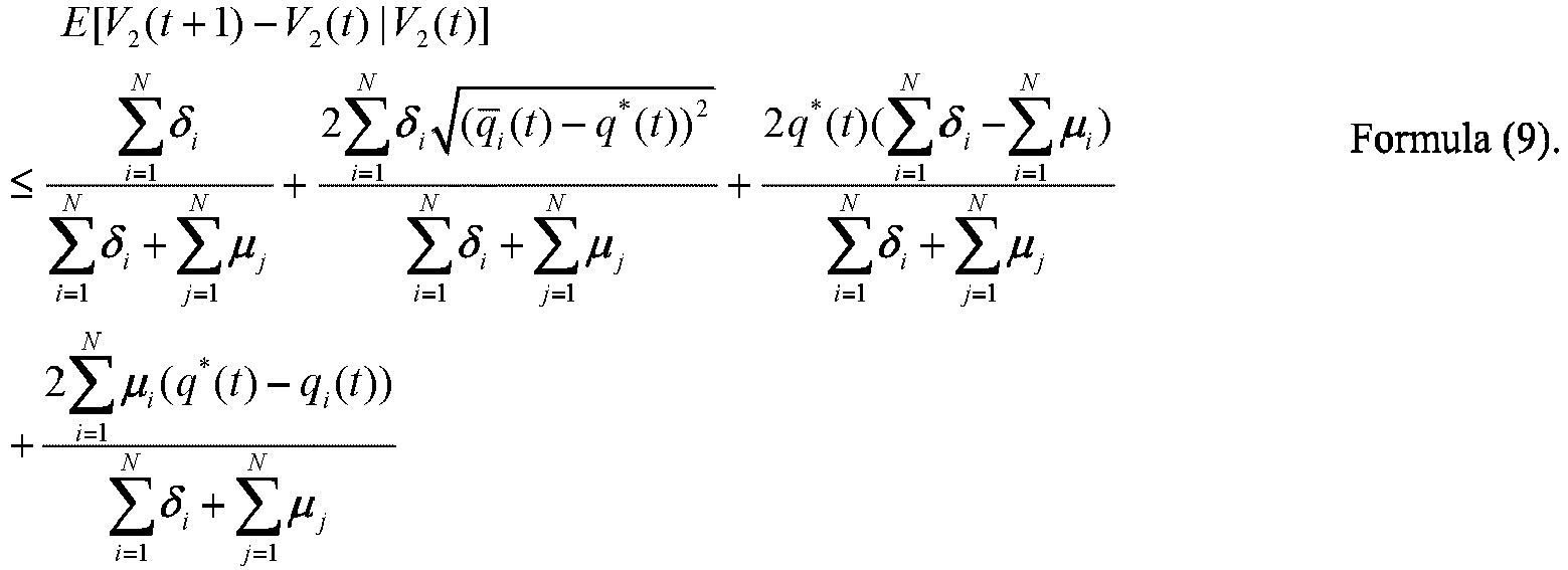
- With reference to Formula (6) and Formula (9), the following formula is obtained:

- Then, define:

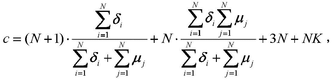
the following formula is obtained:
- Because q ∗(t) is the global optimal solution, q ∗(t) ≤ qi (t), and further, the following formula is obtained:

- An initial condition of the queuing model is


- It is assumed that in the (1, 1) policy, if a queuing system is not converged to the global optimal solution, t definitely exists. Therefore, when t is set to be large enough, a value of a Lyapunov function V(t) is very large. Because V(t) = V1(t) + V2(t), at least one value of V1(t) and V2(t) is very large.
- It is assumed that the value of V1(t) is very large. Because


- Therefore, there definitely exists a value ti such that:

- In this case, substitute Formula (11), Formula (12), and Formula (13) to Formula (10), and find the following:

- In other words, there exists ε>0 such that:

- The Lyapunov function has a step of negatively expected drift. In other words, the (1, 1) policy is converged to a JSQ policy of the global optimal solution, and this is contradictory to the hypothesis. Therefore, the value of V1(t) cannot be very large.
- If the value of V2(t) is very large, it indicates that there definitely exists a value t2, and when t ≥ t 2, loads of a full queue are heavy, and a value of qi (t) is very large and keeps increasing. It is assumed that the value of a global optimal solution q ∗(t) is not large in this case, in other words, a difference between values of q ∗(t) and qi (t) is very large. Because the value of c is a fixed value, then:

- Based on a property of a perfect square, the following formula is obtained:

- Substitute Formula (12), Formula (14), and Formula (15) to Formula (10), and find the following:

- In other words, there exists ε > 0 such that:

- The Lyapunov function has a step of negatively expected drift. In other words, the (1, 1) policy is converged to the global optimal solution, and this is contradictory to the hypothesis. Therefore, the value of V2(t) cannot be very large.
- It is assumed that a value of the global optimal solution q ∗(t) is also very large in this case. Then, a difference between values of q ∗(t) and qi (t) is not large. In this case, although Formula (15) is not true, there definitely exists t ≥ t 3 such that:

- Substitute Formula (11), Formula (15), and Formula (16) to Formula (10), and find the following:

- In other words, there exists ε > 0 such that:

- The Lyapunov function has a step of negatively expected drift. In other words, the (1, 1) policy is converged to the global optimal solution, and this is contradictory to the hypothesis. Therefore, the value of V2(t) cannot be very large.
- So far, cases in which the Lyapunov function is not converged are all excluded. Therefore, it can be inferred that, in the (1, 1) policy ensures, a scheduling result is converged to the global optimal solution when a time is long enough. Therefore, the (1, 1) policy is stable. Still further, for an embodiment of a (d, m) policy (d > 1 or m > 1) with a faster convergence speed, convergence is stronger. Therefore, the load balancing policy according to this embodiment is convergent.
- To further describe the technical effect of this embodiment, a three-layer DCN architecture shown in
FIG. 5 is constructed on a simulation platform OMNET+ (Objective Modular Network Testbed in C++), and convergence of the solution of the present invention is verified by analyzing a data transmission effect in the network architecture. In the DCN architecture, each end node (for example, a server) randomly generates a data flow according to Poisson distribution, a destination address of the data flow is random, and a size of a data packet complies with heavy-tailed distribution. As shown inFIG. 6 , in this embodiment of this application, when the target path is determined through the local optimal solution, a maximum difference between lengths of output queues of ports at any moment does not exceed a difference between N1 and N2. It can be learned that load balancing can be implemented by using the target path determined through the local optimal solution. - Optionally, for every one or more to-be-transmitted data packets that need to be sent by the source end to the destination end, the target path may be determined once by performing step 201. Specifically, before step 201, the method may further include the following step:
- The source end determines whether the to-be-transmitted data packet and a transmitted data packet belong to a same scheduling unit.
- When the to-be-transmitted data packet and the transmitted data packet do not belong to the same scheduling unit, the source end performs step 201.
- When the to-be-transmitted data packet and the transmitted data packet belong to the same scheduling unit, a target path of the transmitted data packet is used as a target path of the to-be-transmitted data packet.
- Optionally, the determining whether the to-be-transmitted data packet and a transmitted data packet belong to a same scheduling unit includes: determining whether the to-be-transmitted data packet and a transmitted data packet that is transmitted within second preset duration belong to a same scheduling unit. Optionally, the scheduling unit includes a data packet, a flow, or a set of a plurality of data packets in a same flow.
- Optionally, the first preset duration may be less than or equal to the second preset duration.
- Step 202: The source end sends the bandwidth probe packet to the destination end through the probe channel on the target path.
- In this step, optionally, a packet header of the bandwidth probe packet may include a path identifier corresponding to the target path, so that the intermediate device forwards the bandwidth probe packet to the destination end through the probe channel on the target path based on the path identifier.
- Step 203: The destination end returns the bandwidth probe packet to the source end.
- Step 204: The source end sends, based on the bandwidth probe packet returned by the destination end, the to-be-transmitted data packet to the destination end through a data channel on the target path.
- In this step, optionally, a packet header of the to-be-transmitted data packet may include a path identifier corresponding to the target path, so that the intermediate device forwards the to-be-transmitted data packet to the destination end through the probe channel on the target path based on the path identifier.
- It should be noted that an objective of
step 202 to step 204 is to adjust a data packet rate on the data channel based on a packet loss rate of the bandwidth probe packet limited by the probe channel on the target path, and the like. A specific manner of adjusting the data packet rate on the data channel based on the packet loss rate of the bandwidth probe packet limited by the probe channel on the target path, and the like is not limited in this embodiment of this application. - In this embodiment, the source end determines, based on the load statuses of the respective probe channels on the n paths between the source end and the destination end, the target path with the lightest load in the n paths, and sends the bandwidth probe packet to the destination end through the probe channel on the target path; the destination end returns the bandwidth probe packet to the source end; and the source end sends the to-be-transmitted data packet to the destination end through the data channel on the target path based on the bandwidth probe packet returned by the destination end. Therefore, the target path with the lightest load is selected based on the load statuses of the respective probe channels on the n paths, thereby implementing load balancing among a plurality of paths.
-
FIG. 7 is a flowchart of an unclaimed,Embodiment 2 of a load balancing method according to an embodiment of this application. As shown inFIG. 7 , based on the foregoing method embodiment, in this embodiment, an example in which a scheduling unit is a flow and a path identifier is a TTL is used for the following description. As shown inFIG. 7 , the method according to this embodiment may include the following steps. - Step 701: When a to-be-transmitted data packet needs to be sent to a destination end, a source end queries whether a flow table of the source end includes a valid path of a data flow to which the to-be-transmitted data packet belongs.
- In this step, when the flow table includes a correspondence between an identifier of the data flow to which the to-be-transmitted data packet belongs and a forwarding path, and a valid status is valid, it may be determined that the flow table includes the valid path of the data flow to which the to-be-transmitted data packet belongs. When the flow table includes the correspondence between the identifier of the data flow to which the to-be-transmitted data packet belongs and the forwarding path, but the valid status is invalid, or when the flow table does not include a correspondence between the identifier of the data flow to which the to-be-transmitted data packet belongs and an identifier of the target path, it may be determined that the flow table does not include the valid path of the data flow to which the to-be-transmitted data packet belongs. For example, as shown in
FIG. 8A , a table entry of the flow table of the source end may record a flow identifier (Flow ID), a forwarding path, an aging bit, and a valid bit. When the valid bit is set to true, it may be considered that the valid status is valid; and when the valid bit is set to false, it may be considered that the valid status is invalid. - Optionally, valid duration of information in the flow table may be limited to second preset duration. In other words, the flow table may be periodically updated based on the second preset duration. Specifically, the following flow table information update operation may be performed by using the second preset duration as a period:
- if the aging bit is set to false, resetting a value of the aging bit to true; and
- if the aging bit is set to true, changing a value of the valid bit to false.
- It indicates that a flow table in which information is periodically updated may be generated in the source end. A validity period of each data flow in the flow table is the second preset duration, and a corresponding data packet that arrives within the validity period is scheduled based on a forwarding path in the flow table.
- When the flow table of the source end does not include the valid path of the data flow to which the to-be-transmitted data packet belongs, the following
step 702 is performed. When the flow table of the source end includes the valid path of the data flow to which the to-be-transmitted data packet belongs, the followingstep 708 is performed. - Step 702: The source end randomly selects m TTL values to mark m paths to the destination end, and records the m paths as a candidate path set.
- Step 703: The source end adds, to the candidate path set, d optimal paths that are obtained when determining the target path last time.
- In this step, optionally, the source end may maintain a path status table, to record n paths from the source end to the destination end and respective load statuses of the n paths. For example, as shown in
FIG. 8B , a path status table may record a destination end identifier (DestID) such as a destination end address; a TTL value of a path such as a TTL value of apath 1 Hashl_index, a TTL value of apath 2 Hash2_index, and a TTL value of apath 3 Hash3_index; and a load status of the path such as a load status of thepath 1 Hash1_metric, a load status of thepath 2 Hash2_metric, and a load status of thepath 3 Hash3_metric. Specifically, the d paths may be determined based on the path status table. - Optionally, the path status table may be periodically updated by using first preset duration as a period. Specifically, step 702 to step 704 may be performed to update the path status table.
- It should be noted that, for specific descriptions of the d paths, reference may be made to the foregoing embodiment, and details are not described herein again. The candidate path set herein may be understood as a path set formed by the foregoing n paths.
- Step 704: The source end probes a load status of each path in the candidate path set.
- In this step, specifically, the load status of each path in the candidate path set may be probed by performing
step 2011 to step 2013. After the load status of each path in the candidate path set is probed, the path status table may be updated based on the load status of each path. - Step 705: The source end determines a target path with a lightest load based on the load status of each path.
- Step 706: The source end sends a bandwidth probe packet to the destination end through a probe channel on the target path, receives the bandwidth probe packet returned by the destination end, and sends a to-be-transmitted data packet to the destination end through a data channel on the target path based on the received bandwidth probe packet returned by the destination end.
- In this step, specifically, the to-be-transmitted data packet may be sent to the destination end through the data channel on the target path by performing
step 202 to step 204. - Step 707: The source end updates the flow table by using the target path as a forwarding path of the data flow to which the to-be-transmitted data packet belongs.
- In this step, optionally, the correspondence between the identifier of the data flow to which the to-be-transmitted data packet belongs and the target path may be updated to the flow table, and a valid status is set to valid. It should be noted that, for the flow table shown in
FIG. 8A , after it is determined thatstep 702 needs to be performed, the value of the valid bit may be changed to true. - It should be noted that a sequence of performing
step 707 and step 706 is not limited. - Step 708: The source end sends a bandwidth probe packet to the destination end through a probe channel on the valid path of the data flow to which the to-be-transmitted data packet belongs in the flow table, receives the bandwidth probe packet returned by the destination end, and sends, based on the bandwidth probe packet returned by the destination end, the to-be-transmitted data packet to the destination end through a data channel on the valid path.
- It should be noted that
step 708 is similar to step 706, and details are not described herein. - It should be noted that, for the flow table shown in
FIG. 8A , after it is determined thatstep 708 needs to be performed, the value of the valid bit may be changed to false. - In this embodiment, when the to-be-transmitted data packet needs to be sent to the destination end, the source end queries whether the flow table of the source end includes the valid path of the data flow to which the to-be-transmitted data packet belongs. If the flow table of the source end includes the valid path of the data flow to which the to-be-transmitted data packet belongs, the source end sends the to-be-transmitted data packet to the destination end through the data channel on the valid path of the data flow to which the to-be-transmitted data packet belongs in the flow table. Otherwise, the source end determines the target path with the lightest load based on load statuses of respective probe channels on the n paths, and sends the to-be-transmitted data packet to the destination end through the data channel on the target path. Therefore, with the flow as the scheduling unit, the target path with the lightest load is selected based on the load statuses of the respective probe channels on the n paths, thereby implementing load balancing among a plurality of paths.
-
FIG. 9 is a schematic structural diagram of a source end according to an embodiment of this application. As shown inFIG. 9 , the source end in this embodiment may include apath determining unit 901, a bandwidth probepacket transceiver unit 902, and a datapacket transmitting unit 903. - The
path determining unit 901 is configured to determine, based on load statuses of respective probe channels on n paths between the source end and a destination end, a target path with a lightest load in the n paths, where the probe channel is used to transmit a probe packet, the probe packet includes a bandwidth probe packet, and n is an integer greater than 1. - The bandwidth probe
packet transceiver unit 902 is configured to send a bandwidth probe packet to the destination end through a probe channel on the target path, and receive the bandwidth probe packet returned by the destination end. - The data
packet transmitting unit 903 is configured to send, based on the bandwidth probe packet returned by the destination end, a to-be-transmitted data packet to the destination end through a data channel on the target path. - In an implementable design, the probe packet further includes a load probe packet; and the source end further includes a load probe
packet determining unit 904, configured to: - send a load probe packet to the destination end through a probe channel on each of the n paths, and receive the load probe packet returned by the destination end; and
- determine, based on the load probe packet returned on each path, a load status of the probe channel on each path.
- In an implementable design, that the load probe
packet determining unit 904 is configured to determine, based on the load probe packet returned on each path, a load status of the probe channel on each path specifically includes: using a round trip time RTT or an explicit congestion notification ECN identifier of the load probe packet returned on each path as load status information of the probe channel on each path. - In an implementable design, the load probe
packet determining unit 904 is specifically configured to periodically perform the following steps within first preset duration:
sending the load probe packet to the destination end through the probe channel on each of the n paths, and receiving the load probe packet returned by the destination end; and determining, based on the load probe packet returned on each path, the load status of the probe channel on each path. - In an implementable design, the n paths are in one-to-one correspondence with n path identifiers, and the path identifier is used by an intermediate device to perform routing by using a Hash algorithm; and
the load probe packet that is sent to the destination end through the probe channel on each path includes a path identifier corresponding to a path, where a packet header of the bandwidth probe packet and a packet header of the data packet all include a path identifier corresponding to the target path. - In an implementable design, n is less than a total quantity of paths between the source end and the destination end, and the n path identifiers include randomly determined m path identifiers, and path identifiers respectively corresponding to d paths in all paths used to determine the target path previously, where n is greater than or equal to m and is less than or equal to m + d, and loads of the d paths are less than or equal to a load of another path in all the paths.
- In an implementable design, m is equal to 2.
- In an implementable design, the source end further includes a judging
unit 905, configured to determine whether the to-be-transmitted data packet and a transmitted data packet belong to a same scheduling unit. - The
path determining unit 901 is specifically configured to: when the to-be-transmitted data packet and the transmitted data packet do not belong to the same scheduling unit, determine the target path in the n paths based on the load statuses of the respective probe channels on the n paths between the source end and the destination end. - In an implementable design, the
path determining unit 901 is further configured to: when the to-be-transmitted data packet and the transmitted data packet belong to the same scheduling unit, use a target path of the transmitted data packet as a target path of the to-be-transmitted data packet. - In an implementable design, the judging
module 905 is specifically configured to determine whether the to-be-transmitted data packet and a transmitted data packet that is transmitted within second preset duration belong to a same scheduling unit. - In an implementable design, the scheduling unit includes a data packet, a flow, or a set of a plurality of data packets in a same flow.
- The source end in this embodiment may be configured to execute the technical solution of a source end side according to the embodiments shown in
FIG. 2 andFIG. 7 , implementation principles and technical effects thereof are similar to those in the embodiments shown inFIG. 2 andFIG. 7 , and details are not described herein. -
FIG. 10 is a schematic structural diagram of a destination end according to an embodiment of this application. As shown inFIG 10 , the destination end in this embodiment may include a bandwidth probepacket transceiver unit 1001 and a datapacket receiving unit 1002. - The bandwidth probe
packet transceiver unit 1001 is configured to receive a bandwidth probe packet sent by a source end through a probe channel on a target path, where the target path is a path with a lightest load in n paths that is determined by the source end based on load statuses of respective probe channels on the n paths between the source end and the destination end, the probe channel is used to transmit a probe packet, the probe packet includes the bandwidth probe packet, and n is an integer greater than 1. - The bandwidth probe
packet transceiver unit 1001 is further configured to return the bandwidth probe packet to the source end. - The data
packet receiving unit 1002 is configured to receive a data packet sent by the source end through a data channel on the target path. - In an implementable design, the probe packet further includes a load probe packet; and the destination end further includes a load probe
packet transceiver unit 1003, configured to: - receive a load probe packet sent by the source end through a probe channel on each of the n paths; and
- return the load probe packet received through the probe channel on each path to the source end.
- In an implementable design, the n paths are in one-to-one correspondence with n path identifiers, and the path identifier is used by an intermediate device to perform routing by using a Hash algorithm; and
a packet header of the load probe packet that is sent to the destination end through the probe channel on each path includes a path identifier corresponding to a path, where a packet header of the bandwidth probe packet and a packet header of the data packet all include a path identifier corresponding to the target path. - In an implementable design, n is less than a total quantity of paths between the source end and the destination end, and the n path identifiers include randomly determined m path identifiers, and path identifiers respectively corresponding to d paths in all paths used to determine the target path previously, where n is greater than or equal to m and is less than or equal to m + d, and loads of the d paths are less than or equal to a load of another path in all the paths.
- In an implementable design, m is equal to 2.
- The destination end in this embodiment may be configured to execute the technical solution of a destination end side according to the embodiments shown in
FIG. 2 andFIG. 7 , implementation principles and technical effects thereof are similar to those in the embodiments shown inFIG. 2 andFIG. 7 , and details are not described herein. -
FIG. 11 is a schematic structural diagram of an intermediate device according to an embodiment of this application. As shown inFIG. 11 , the intermediate device in this embodiment may include afirst receiving unit 1101, afirst forwarding unit 1102, asecond receiving unit 1103, and asecond forwarding unit 1104. - The
first receiving unit 1101 is configured to receive a load probe packet sent by a source end; - The
first forwarding unit 1102 is configured to forward the load probe packet to a destination end through a probe channel, where the probe channel is used to transmit a probe packet, and the probe packet includes the load probe packet. - The
second receiving unit 1103 is configured to receive the load probe packet returned by the destination end. - The
second forwarding unit 1104 is configured to forward the load probe packet returned by the destination end to the source end. - In an implementable design, the
first forwarding unit 1102 is specifically configured to:
forward the load probe packet to the destination end through the probe channel based on a queuing policy. - In an implementable design, the
first forwarding unit 1102 is specifically configured to:
forward the load probe packet to the destination end through the probe channel based on a highest priority policy. - In an implementable design, the
second forwarding unit 1104 is specifically configured to:
forward the load probe packet returned by the destination end to the source end based on the highest priority policy. - In an implementable design, a packet header of the load probe packet includes a path identifier; and
that thefirst forwarding unit 1102 is configured to forward the load probe packet to a destination end through a probe channel specifically includes:
forwarding the load probe packet to the destination end through the probe channel based on the path identifier by using a Hash algorithm. - The intermediate device in this embodiment may be configured to execute the technical solution of an intermediate device side according to the embodiments shown in
FIG. 2 andFIG. 7 , implementation principles and technical effects thereof are similar to those in the embodiments shown inFIG. 2 andFIG. 7 , and details are not described herein. - It should be understood that, division of the units of the foregoing communications devices is merely logical function division, and during actual implementation, the units may be all or partially integrated into a physical entity, or may be physically separated. In addition, all of the units may be implemented in a form of software invoked by a processing element or in a form of hardware. Alternatively, some of the units may be implemented in a form of software invoked by a processing element, and some of the units may be implemented in a form of hardware. For example, a transmitting unit may be an independently disposed processing element, or may be integrated into a chip of a network device for implementation. In addition, the transmitting unit may be alternatively stored in a memory of a network device in a form of a program, and a processing element of the network device invokes and executes a function of the transmitting unit. Implementation of the other units is similar to that of the transmitting unit. In addition, all or some of the units may be integrated together, or may be implemented independently. The processing element herein may be an integrated circuit with a signal processing capability. In an implementation process, steps in the foregoing methods or the foregoing units can be implemented by using a hardware integrated logical circuit in the processing element, or by using instructions in a form of software. In addition, the transmitting unit is a transmitting control unit, and may receive information by using a transmitting apparatus of the network device such as an antenna and a radio frequency apparatus.
- The foregoing units may be configured as one or more integrated circuits for implementing the foregoing method, for example, one or more application-specific integrated circuits (Application Specific Integrated Circuit, ASIC), one or more microprocessors (digital signal processor, DSP), or one or more field programmable gate arrays (Field Programmable Gate Array, FPGA). For another example, when one of the foregoing units is implemented by a processing element by invoking a program, the processing element may be a general-purpose processor, for example, a central processing unit (Central Processing Unit, CPU) or another processor that can invoke the program. For another example, the units may be integrated together, and implemented in a form of a system on chip (system-on-a-chip, SOC).
-
FIG. 12 is a schematic diagram of a hardware structure of a communications device according to an embodiment of this application. Thecommunications device 120 includes at least oneprocessor 1201, acommunications bus 1202, amemory 1203, and at least onecommunications interface 1204. - The
processor 1201 may be a central processing unit (central processing unit, CPU), a microprocessor, an application-specific integrated circuit (application-specific integrated circuit, ASIC), or one or more integrated circuits configured to control program execution in the solutions of this application. - The
communications bus 1202 may include a channel, to transfer information between the foregoing components. - The
communications interface 1204 uses any apparatus such as a transceiver to communicate with another device or a communications network, such as the Ethernet, a radio access network (radio access network, RAN), or a wireless local area network (wireless local area networks, WLAN). - The
memory 1203 may be a read-only memory (read-only memory, ROM), another type of static storage device that can store static information and instructions, a random access memory (random access memory, RAM), or another type of dynamic storage device that can store information and instructions; or may be an electrically erasable programmable read-only memory (electrically erasable programmable read-only memory, EEPROM), a compact disc read-only memory (compact disc read-only memory, CD-ROM) or another optical disk storage, an optical disc storage (including a compact optical disc, a laser disc, an optical disc, a digital versatile disc, a Blu-ray disc, or the like), a magnetic disk storage medium or another magnetic storage device, or any other medium capable of carrying or storing expected program code in a form of instructions or data structures and capable of being accessed by a computer, but is not limited thereto. The memory may exist independently, and is connected to the processor by using a bus. The memory may be alternatively integrated with the processor. - The
memory 1203 is configured to store application program code for executing the solution of this application, and theprocessor 1201 controls the execution. Theprocessor 1201 is configured to execute the application program code stored in thememory 1203, to implement the load balancing method according to the foregoing embodiments of this application. - Alternatively, optionally, in this embodiment of this application, the
processor 1201 may perform processing-related functions in the load balancing method provided in the foregoing embodiments, and thecommunications interface 1204 is responsible for communicating with another device or a communications network. This is not specifically limited in this embodiment of this application. - In specific implementation, in an embodiment, the
processor 1201 may include one or more CPUs. - In specific implementation, in an embodiment, the
communications device 120 may include a plurality of processors. Each of the processors may be a single-core processor (single-CPU), or may be a multicore processor (multi-CPU). The processors herein may be one or more devices, circuits, and/or processing cores for processing data (for example, computer program instructions). - In specific implementation, in an embodiment, the
communications device 120 may further include an output device and an input device. The output device communicates with theprocessor 1201, and may display information in a plurality of manners. For example, the output device may be a liquid crystal display (liquid crystal display, LCD), a light emitting diode (light emitting diode, LED) display device, a cathode ray tube (cathode ray tube, CRT) display device, a projector (projector), or the like. The input device communicates with theprocessor 1201, and may receive input of a user in a plurality of manners. For example, the input device may be a mouse, a keyboard, a touchscreen device, a sensor device, or the like. - In addition, as described above, the
communications device 120 according to this embodiment of this application may be a chip, or a source end, or a destination end, or an intermediate device, or a device having a structure similar to that inFIG. 12 . A type of thecommunications device 120 is not limited in this embodiment of this application. - In this embodiment, the
communications device 120 is presented with the function modules implemented through integration. The "module" herein may be an application-specific integrated circuit (Application-Specific Integrated Circuit, ASIC), a circuit, a processor and a memory that execute one or more software programs or firmware programs, an integrated logic circuit, and/or another device that can provide the foregoing function. In a simple embodiment, a person skilled in the art may figure out that thecommunications device 120 may use the form shown inFIG. 12 . For example, the function/implementation process of the units inFIG. 9 to FIG. 11 may be implemented by theprocessor 1201 and thememory 1203 inFIG. 12 . Specifically, the path determining unit inFIG. 9 may be executed by theprocessor 1201 by invoking the application program code stored in thememory 1203, and this is not limited in this embodiment of this application. Alternatively, the bandwidth probe packet transceiver unit inFIG. 9 may be implemented by using thecommunications interface 1204 inFIG. 12 , and this is not limited in this embodiment of this application. - It should be noted that the communications device according to this embodiment shown in
FIG. 12 may be specifically the source end in the embodiment shown inFIG. 2 orFIG. 7 . When theprocessor 1201 invokes the program stored in thememory 1203, the method on the source end side according to the embodiment shown inFIG. 2 orFIG. 7 may be performed. - It should be noted that the communications device according to this embodiment shown in
FIG. 12 may be specifically the destination end in the embodiment shown inFIG. 2 orFIG. 7 . When theprocessor 1201 invokes the program stored in thememory 1203, the method on the destination end side according to the embodiment shown inFIG. 2 orFIG. 7 may be performed. - It should be noted that the communications device according to this embodiment shown in
FIG. 12 may be specifically the intermediate device in the embodiment shown inFIG. 2 orFIG. 7 . When theprocessor 1201 invokes the program stored in thememory 1203, the method on the intermediate device side according to the embodiment shown inFIG. 2 orFIG. 7 may be performed. - Optionally, an embodiment of this application provides a communications system. The communications system may include the source end, the destination end, and the intermediate device in any one of the foregoing embodiments.
- All or some of the foregoing embodiments may be implemented by using software, hardware, firmware, or any combination thereof. When a software program is used to implement the embodiments, the embodiments may be implemented completely or partially in a form of a computer program product. The computer program product includes one or more computer instructions. When the computer program instructions are loaded and executed on a computer, the procedure or functions according to the embodiments of this application are all or partially generated. The computer may be a general-purpose computer, a dedicated computer, a computer network, or another programmable apparatus. The computer instructions may be stored in a computer readable storage medium or may be transmitted from a computer readable storage medium to another computer readable storage medium. For example, the computer instructions may be transmitted from a website, computer, server, or data center to another website, computer, server, or data center in a wired (for example, a coaxial cable, an optical fiber, or a digital subscriber line (Digital Subscriber Line, DSL)) or wireless (for example, infrared, radio, or microwave) manner. The computer readable storage medium may be any usable medium accessible by a computer, or a data storage device, such as a server or a data center, integrating one or more usable media. The usable medium may be a magnetic medium (for example, a floppy disk, a hard disk, or a magnetic tape), an optical medium (for example, a DVD), a semiconductor medium (for example, a solid-state drive (Solid State Disk, SSD)), or the like.
Claims (7)
- A load balancing method performed by a source end, comprising:determining (201), based on load statuses of respective probe channels on n paths between the source end and a destination end, a target path with a lightest load in the n paths, wherein for each of the n paths transmission channels between the source end and the destination end are classified into a data channel used to transmit a data packet and a probe channel used to transmit a probe packet that comprises a bandwidth probe packet, wherein a data packet rate on the data channel is adjusted based on a packet loss rate of a bandwidth probe packet limited by the probe channel, wherein the bandwidth probe packet is used to probe an available bandwidth, and wherein n is an integer greater than 1;sending (202) a bandwidth probe packet to the destination end through a probe channel on the target path, and receiving (203) the bandwidth probe packet returned by the destination end; andsending (204), based on the bandwidth probe packet returned by the destination end, a to-be-transmitted data packet to the destination end through a data channel on the target path;wherein the probe packet further comprises a load probe packet; andbefore the determining, based on load statuses of respective probe channels on n paths between a source end and a destination end, a target path with a lightest load in the n paths, the method further comprises:sending (2011) a load probe packet to the destination end through a probe channel on each of the n paths, and receiving (2012) the load probe packet returned by the destination end; anddetermining, based on the load probe packet returned on each path, a load status of the probe channel on each path (2013), and wherein the load status of the probe channel on each path reflects a load status of the data channel on each path.
- The method according to claim 1, wherein the determining, based on the load probe packet returned on each path, a load status of the probe channel on each path comprises: using a round trip time ,RTT, or an explicit congestion notification ,ECN, identifier of the load probe packet returned on each path as load status information of the probe channel on each path.
- The method according to claim 1 or 2, wherein the following steps are periodically performed within first preset duration:
sending the load probe packet to the destination end through the probe channel on each of the n paths, and receiving the load probe packet returned by the destination end; and determining, based on the load probe packet returned on each path, the load status of the probe channel on each path. - The method according to any one of claims 1 to 3, wherein before the determining, based on load statuses of respective probe channels on n paths between a source end and a destination end, a target path with a lightest load in the n paths, the method further comprises:determining whether the to-be-transmitted data packet and a transmitted data packet belong to a same scheduling unit, wherein the scheduling unit includes a data packet, a flow, or a set of a plurality of data packets in a same flow; andwhen the to-be-transmitted data packet and the transmitted data packet do not belong to the same scheduling unit, performing the step of determining, based on load statuses of respective probe channels on n paths between a source end and a destination end, a target path with a lightest load in the n paths.
- The method according to claim 4, wherein the method further comprises:
when the to-be-transmitted data packet and the transmitted data packet belong to the same scheduling unit, using a target path of the transmitted data packet as a target path of the to-be-transmitted data packet. - The method according to claim 4 or 5, wherein the determining whether the to-be-transmitted data packet and a transmitted data packet belong to a same scheduling unit comprises:
determining whether the to-be-transmitted data packet and a transmitted data packet that is transmitted within second preset duration belong to a same scheduling unit. - A load balancing method performed by a destination end, comprisingreceiving (202) a bandwidth probe packet sent by a source end through a probe channel on a target path, wherein the target path is a path with a lightest load in n paths that is determined by the source end based on load statuses of respective probe channels on the n paths between the source end and the destination end, wherein for each of the n paths transmission channels between the source end and the destination end are classified into a data channel used to transmit a data packet and a probe channel used to transmit a probe packet that comprises a bandwidth probe packet, wherein a data packet rate on the data channel is adjusted based on a packet loss rate of a bandwidth probe packet limited by the probe channel, wherein the bandwidth probe packet is used to probe an available bandwidth, and wherein n is an integer greater than 1;returning (203) the bandwidth probe packet to the source end; andreceiving a data packet sent by the source end through a data channel on the target path;wherein the probe packet further comprises a load probe packet; and before the receiving a bandwidth probe packet sent by a source end through a probe channel on a target path, the method further comprises:receiving (2011) a load probe packet sent by the source end through a probe channel on each of the n paths; andreturning (2012) the load probe packet received through the probe channel on each path to the source end, and wherein the load status of the probe channel on each path reflects a load status of the data channel on each path.
Applications Claiming Priority (2)
| Application Number | Priority Date | Filing Date | Title |
|---|---|---|---|
| CN201810333794.1A CN108390820B (en) | 2018-04-13 | 2018-04-13 | Load balancing method, equipment and system |
| PCT/CN2019/079302 WO2019196630A1 (en) | 2018-04-13 | 2019-03-22 | Load balancing method, equipment and system |
Publications (3)
| Publication Number | Publication Date |
|---|---|
| EP3767897A1 EP3767897A1 (en) | 2021-01-20 |
| EP3767897A4 EP3767897A4 (en) | 2021-04-21 |
| EP3767897B1 true EP3767897B1 (en) | 2023-06-14 |
Family
ID=63072788
Family Applications (1)
| Application Number | Title | Priority Date | Filing Date |
|---|---|---|---|
| EP19784281.8A Active EP3767897B1 (en) | 2018-04-13 | 2019-03-22 | Load balancing method |
Country Status (4)
| Country | Link |
|---|---|
| US (1) | US11876715B2 (en) |
| EP (1) | EP3767897B1 (en) |
| CN (1) | CN108390820B (en) |
| WO (1) | WO2019196630A1 (en) |
Families Citing this family (20)
| Publication number | Priority date | Publication date | Assignee | Title |
|---|---|---|---|---|
| CN108390820B (en) | 2018-04-13 | 2021-09-14 | 华为技术有限公司 | Load balancing method, equipment and system |
| CN109067664B (en) * | 2018-08-29 | 2022-06-10 | 迈普通信技术股份有限公司 | Load balancing method and device |
| CN111901237B (en) * | 2019-05-06 | 2021-06-08 | 清华大学 | Source routing method and system, related device and computer-readable storage medium |
| CN110380981B (en) * | 2019-07-19 | 2022-10-28 | 厦门网宿有限公司 | Flow distribution method and equipment |
| CN110417674B (en) * | 2019-07-26 | 2022-06-21 | 新华三技术有限公司合肥分公司 | Data traffic sharing method and device |
| CN114208131B (en) * | 2019-08-12 | 2024-09-27 | 华为技术有限公司 | Traffic balancing method, network device and electronic device |
| CN115462049B (en) * | 2020-05-18 | 2024-03-08 | 阿里巴巴(中国)有限公司 | Forwarding path planning method for large-scale data network center |
| EP4149066A4 (en) | 2020-05-30 | 2023-11-01 | Huawei Technologies Co., Ltd. | Communication method and apparatus |
| JP7387563B2 (en) * | 2020-09-14 | 2023-11-28 | 株式会社東芝 | Wireless communication device, wireless communication system, wireless communication method and program |
| CN112187654A (en) * | 2020-09-28 | 2021-01-05 | 太仓市同维电子有限公司 | Shunting method for multi-connection communication |
| US12375405B2 (en) * | 2021-03-09 | 2025-07-29 | Nokia Solutions And Networks Oy | Path congestion notification |
| CN116670660A (en) * | 2021-03-17 | 2023-08-29 | 北京希姆计算科技有限公司 | Network-on-chip simulation model generation method, device, electronic device, and computer-readable storage medium |
| CN117397224A (en) * | 2021-06-11 | 2024-01-12 | 华为技术有限公司 | Data transmission method and communication device |
| US12341679B2 (en) * | 2021-07-12 | 2025-06-24 | Cisco Technology, Inc. | Path assurance in shared transport |
| CN113810459B (en) * | 2021-07-29 | 2024-11-01 | 奇安信科技集团股份有限公司 | Data transmission method, device, electronic equipment and storage medium |
| CN113676405B (en) * | 2021-08-18 | 2022-10-14 | 上海晨驭信息科技有限公司 | Load sharing-based rapid link master-slave switching distributed system and method |
| CN116193463A (en) * | 2021-11-26 | 2023-05-30 | 华为技术有限公司 | A data processing method, message sending method and device |
| US12184557B2 (en) * | 2022-01-04 | 2024-12-31 | VMware LLC | Explicit congestion notification in a virtual environment |
| CN116489091B (en) * | 2023-03-28 | 2025-08-15 | 清华大学 | Flow scheduling method and device based on remote in-band telemetry and time delay |
| CN116647878A (en) * | 2023-07-21 | 2023-08-25 | 北京最终前沿深空科技有限公司 | Load balancing method, device, equipment and storage medium for satellite network |
Citations (1)
| Publication number | Priority date | Publication date | Assignee | Title |
|---|---|---|---|---|
| US20160164778A1 (en) * | 2009-01-09 | 2016-06-09 | Microsoft Technology Licensing, Llc | Server-centric high performance network architecture for modular data centers |
Family Cites Families (19)
| Publication number | Priority date | Publication date | Assignee | Title |
|---|---|---|---|---|
| US9197533B1 (en) * | 2005-05-09 | 2015-11-24 | Cisco Technology, Inc. | Technique for maintaining and enforcing relative policies with thresholds |
| US7643427B2 (en) * | 2006-03-28 | 2010-01-05 | Nec Laboratories America, Inc. | Multipath routing architecture for large data transfers |
| EP2005671B1 (en) * | 2006-04-13 | 2011-06-08 | Dolby Laboratories Licensing Corporation | Estimating wireless processing device queue length and estimating signal reception quality in a wireless network |
| EP2103053B1 (en) * | 2006-12-08 | 2010-08-25 | Iwics Inc. | Enhanced data transport protocol for a multi-station network |
| CN101272290B (en) * | 2008-05-12 | 2011-05-11 | 中国电信股份有限公司 | Measuring method, measuring apparatus for route congestion state in IP network |
| WO2009149444A1 (en) * | 2008-06-06 | 2009-12-10 | Feedtext, Inc. | Free short messaging service/multimedia messaging service system and related method of operating the same |
| CN103312607B (en) * | 2012-03-09 | 2016-12-21 | 华为技术有限公司 | A kind of selection of transmission paths method and device |
| CN103051709A (en) * | 2012-12-20 | 2013-04-17 | 新浪网技术(中国)有限公司 | Data transmission path determination method, network node and content delivery network system |
| US10778584B2 (en) * | 2013-11-05 | 2020-09-15 | Cisco Technology, Inc. | System and method for multi-path load balancing in network fabrics |
| JP6323107B2 (en) * | 2014-03-25 | 2018-05-16 | 富士通株式会社 | Switch device, information processing system, and control method of switch device |
| CN104836750B (en) | 2015-05-04 | 2017-12-05 | 大连理工大学 | A kind of data center network stream scheduling method based on round-robin |
| CN105025525B (en) * | 2015-07-22 | 2018-09-07 | 中国科学院计算技术研究所 | A kind of channel loading equilibrium system and method for multichannel wireless local area networks |
| CN107852372B (en) * | 2015-08-06 | 2021-05-11 | 英国电讯有限公司 | packet network |
| KR101768696B1 (en) * | 2016-01-15 | 2017-08-17 | 울산과학기술원 | network switch for performing priority queuing |
| CN105610709B (en) | 2016-02-03 | 2018-09-11 | 西安电子科技大学 | Big current load equilibrium System and method for based on SDN |
| US10355981B1 (en) * | 2016-03-02 | 2019-07-16 | Innovium, Inc. | Sliding windows |
| US10320681B2 (en) * | 2016-04-12 | 2019-06-11 | Nicira, Inc. | Virtual tunnel endpoints for congestion-aware load balancing |
| CN107786440B (en) * | 2016-08-26 | 2021-05-11 | 华为技术有限公司 | Method and device for forwarding data message |
| CN108390820B (en) * | 2018-04-13 | 2021-09-14 | 华为技术有限公司 | Load balancing method, equipment and system |
-
2018
- 2018-04-13 CN CN201810333794.1A patent/CN108390820B/en active Active
-
2019
- 2019-03-22 EP EP19784281.8A patent/EP3767897B1/en active Active
- 2019-03-22 WO PCT/CN2019/079302 patent/WO2019196630A1/en not_active Ceased
-
2020
- 2020-10-13 US US17/069,378 patent/US11876715B2/en active Active
Patent Citations (1)
| Publication number | Priority date | Publication date | Assignee | Title |
|---|---|---|---|---|
| US20160164778A1 (en) * | 2009-01-09 | 2016-06-09 | Microsoft Technology Licensing, Llc | Server-centric high performance network architecture for modular data centers |
Also Published As
| Publication number | Publication date |
|---|---|
| CN108390820A (en) | 2018-08-10 |
| EP3767897A4 (en) | 2021-04-21 |
| WO2019196630A1 (en) | 2019-10-17 |
| US20210029041A1 (en) | 2021-01-28 |
| EP3767897A1 (en) | 2021-01-20 |
| US11876715B2 (en) | 2024-01-16 |
| CN108390820B (en) | 2021-09-14 |
Similar Documents
| Publication | Publication Date | Title |
|---|---|---|
| US11876715B2 (en) | Load balancing method, device, and system | |
| US10063488B2 (en) | Tracking queuing delay and performing related congestion control in information centric networking | |
| Bai et al. | Enabling {ECN} in {Multi-Service}{Multi-Queue} Data Centers | |
| EP1810466B1 (en) | Directional and priority based flow control between nodes | |
| US20080298248A1 (en) | Method and Apparatus For Computer Network Bandwidth Control and Congestion Management | |
| CN106998302B (en) | Method and device for allocating service flow | |
| US20170339062A1 (en) | Congestion avoidance in a network device | |
| US20050147032A1 (en) | Apportionment of traffic management functions between devices in packet-based communication networks | |
| EP3588880B1 (en) | Method, device, and computer program for predicting packet lifetime in a computing device | |
| CN114079638B (en) | Data transmission method, device and storage medium for multi-protocol hybrid network | |
| US11050649B2 (en) | Delay measurement method of network node device, apparatus, and network node device | |
| US20220038374A1 (en) | Microburst detection and management | |
| CN111371634A (en) | A communication method, device and system | |
| EP3334101B1 (en) | Load balancing eligible packets in response to a policing drop decision | |
| US20220124054A1 (en) | Packet processing method and apparatus, and communications device | |
| Avci et al. | Congestion aware priority flow control in data center networks | |
| US20260074998A1 (en) | Congestion control method, apparatus, and system | |
| EP3186927B1 (en) | Improved network utilization in policy-based networks | |
| US12432165B2 (en) | Multi-packet sliding window scheduler and method for input-queued switches | |
| US11012378B2 (en) | Methods and apparatus for shared buffer allocation in a transport node | |
| WO2021244404A1 (en) | Data processing method and device | |
| Hu et al. | Dynamic queuing sharing mechanism for per-flow quality of service control | |
| CN116155824B (en) | Network congestion data processing method, device, system and computer equipment | |
| EP4597974A1 (en) | Method for adaptive routing in high-performance computers | |
| Nejakar et al. | Development of modified RED AQM algorithm in computer network for congestion control |
Legal Events
| Date | Code | Title | Description |
|---|---|---|---|
| STAA | Information on the status of an ep patent application or granted ep patent |
Free format text: STATUS: THE INTERNATIONAL PUBLICATION HAS BEEN MADE |
|
| PUAI | Public reference made under article 153(3) epc to a published international application that has entered the european phase |
Free format text: ORIGINAL CODE: 0009012 |
|
| STAA | Information on the status of an ep patent application or granted ep patent |
Free format text: STATUS: REQUEST FOR EXAMINATION WAS MADE |
|
| 17P | Request for examination filed |
Effective date: 20201014 |
|
| AK | Designated contracting states |
Kind code of ref document: A1 Designated state(s): AL AT BE BG CH CY CZ DE DK EE ES FI FR GB GR HR HU IE IS IT LI LT LU LV MC MK MT NL NO PL PT RO RS SE SI SK SM TR |
|
| AX | Request for extension of the european patent |
Extension state: BA ME |
|
| A4 | Supplementary search report drawn up and despatched |
Effective date: 20210324 |
|
| RIC1 | Information provided on ipc code assigned before grant |
Ipc: H04L 12/707 20130101AFI20210318BHEP Ipc: H04W 28/08 20090101ALI20210318BHEP Ipc: H04L 12/801 20130101ALI20210318BHEP Ipc: H04L 12/44 20060101ALI20210318BHEP Ipc: H04L 12/803 20130101ALI20210318BHEP Ipc: H04L 12/841 20130101ALI20210318BHEP |
|
| DAV | Request for validation of the european patent (deleted) | ||
| DAX | Request for extension of the european patent (deleted) | ||
| REG | Reference to a national code |
Ref country code: DE Ref legal event code: R079 Free format text: PREVIOUS MAIN CLASS: H04L0012707000 Ipc: H04W0028080000 Ref country code: DE Ref legal event code: R079 Ref document number: 602019031104 Country of ref document: DE Free format text: PREVIOUS MAIN CLASS: H04L0012707000 Ipc: H04W0028080000 |
|
| GRAP | Despatch of communication of intention to grant a patent |
Free format text: ORIGINAL CODE: EPIDOSNIGR1 |
|
| STAA | Information on the status of an ep patent application or granted ep patent |
Free format text: STATUS: GRANT OF PATENT IS INTENDED |
|
| RIC1 | Information provided on ipc code assigned before grant |
Ipc: H04L 47/283 20220101ALI20230119BHEP Ipc: H04L 45/00 20220101ALI20230119BHEP Ipc: H04L 47/33 20220101ALI20230119BHEP Ipc: H04L 47/125 20220101ALI20230119BHEP Ipc: H04L 47/11 20220101ALI20230119BHEP Ipc: H04L 12/44 20060101ALI20230119BHEP Ipc: H04W 28/08 20090101AFI20230119BHEP |
|
| INTG | Intention to grant announced |
Effective date: 20230214 |
|
| GRAS | Grant fee paid |
Free format text: ORIGINAL CODE: EPIDOSNIGR3 |
|
| GRAA | (expected) grant |
Free format text: ORIGINAL CODE: 0009210 |
|
| STAA | Information on the status of an ep patent application or granted ep patent |
Free format text: STATUS: THE PATENT HAS BEEN GRANTED |
|
| AK | Designated contracting states |
Kind code of ref document: B1 Designated state(s): AL AT BE BG CH CY CZ DE DK EE ES FI FR GB GR HR HU IE IS IT LI LT LU LV MC MK MT NL NO PL PT RO RS SE SI SK SM TR |
|
| REG | Reference to a national code |
Ref country code: CH Ref legal event code: EP |
|
| REG | Reference to a national code |
Ref country code: DE Ref legal event code: R096 Ref document number: 602019031104 Country of ref document: DE |
|
| REG | Reference to a national code |
Ref country code: AT Ref legal event code: REF Ref document number: 1580128 Country of ref document: AT Kind code of ref document: T Effective date: 20230715 |
|
| REG | Reference to a national code |
Ref country code: LT Ref legal event code: MG9D |
|
| REG | Reference to a national code |
Ref country code: NL Ref legal event code: MP Effective date: 20230614 |
|
| PG25 | Lapsed in a contracting state [announced via postgrant information from national office to epo] |
Ref country code: SE Free format text: LAPSE BECAUSE OF FAILURE TO SUBMIT A TRANSLATION OF THE DESCRIPTION OR TO PAY THE FEE WITHIN THE PRESCRIBED TIME-LIMIT Effective date: 20230614 Ref country code: NO Free format text: LAPSE BECAUSE OF FAILURE TO SUBMIT A TRANSLATION OF THE DESCRIPTION OR TO PAY THE FEE WITHIN THE PRESCRIBED TIME-LIMIT Effective date: 20230914 Ref country code: ES Free format text: LAPSE BECAUSE OF FAILURE TO SUBMIT A TRANSLATION OF THE DESCRIPTION OR TO PAY THE FEE WITHIN THE PRESCRIBED TIME-LIMIT Effective date: 20230614 |
|
| REG | Reference to a national code |
Ref country code: AT Ref legal event code: MK05 Ref document number: 1580128 Country of ref document: AT Kind code of ref document: T Effective date: 20230614 |
|
| PG25 | Lapsed in a contracting state [announced via postgrant information from national office to epo] |
Ref country code: RS Free format text: LAPSE BECAUSE OF FAILURE TO SUBMIT A TRANSLATION OF THE DESCRIPTION OR TO PAY THE FEE WITHIN THE PRESCRIBED TIME-LIMIT Effective date: 20230614 Ref country code: NL Free format text: LAPSE BECAUSE OF FAILURE TO SUBMIT A TRANSLATION OF THE DESCRIPTION OR TO PAY THE FEE WITHIN THE PRESCRIBED TIME-LIMIT Effective date: 20230614 Ref country code: LV Free format text: LAPSE BECAUSE OF FAILURE TO SUBMIT A TRANSLATION OF THE DESCRIPTION OR TO PAY THE FEE WITHIN THE PRESCRIBED TIME-LIMIT Effective date: 20230614 Ref country code: LT Free format text: LAPSE BECAUSE OF FAILURE TO SUBMIT A TRANSLATION OF THE DESCRIPTION OR TO PAY THE FEE WITHIN THE PRESCRIBED TIME-LIMIT Effective date: 20230614 Ref country code: HR Free format text: LAPSE BECAUSE OF FAILURE TO SUBMIT A TRANSLATION OF THE DESCRIPTION OR TO PAY THE FEE WITHIN THE PRESCRIBED TIME-LIMIT Effective date: 20230614 Ref country code: GR Free format text: LAPSE BECAUSE OF FAILURE TO SUBMIT A TRANSLATION OF THE DESCRIPTION OR TO PAY THE FEE WITHIN THE PRESCRIBED TIME-LIMIT Effective date: 20230915 |
|
| PG25 | Lapsed in a contracting state [announced via postgrant information from national office to epo] |
Ref country code: FI Free format text: LAPSE BECAUSE OF FAILURE TO SUBMIT A TRANSLATION OF THE DESCRIPTION OR TO PAY THE FEE WITHIN THE PRESCRIBED TIME-LIMIT Effective date: 20230614 |
|
| PG25 | Lapsed in a contracting state [announced via postgrant information from national office to epo] |
Ref country code: SK Free format text: LAPSE BECAUSE OF FAILURE TO SUBMIT A TRANSLATION OF THE DESCRIPTION OR TO PAY THE FEE WITHIN THE PRESCRIBED TIME-LIMIT Effective date: 20230614 |
|
| PG25 | Lapsed in a contracting state [announced via postgrant information from national office to epo] |
Ref country code: IS Free format text: LAPSE BECAUSE OF FAILURE TO SUBMIT A TRANSLATION OF THE DESCRIPTION OR TO PAY THE FEE WITHIN THE PRESCRIBED TIME-LIMIT Effective date: 20231014 |
|
| PG25 | Lapsed in a contracting state [announced via postgrant information from national office to epo] |
Ref country code: SM Free format text: LAPSE BECAUSE OF FAILURE TO SUBMIT A TRANSLATION OF THE DESCRIPTION OR TO PAY THE FEE WITHIN THE PRESCRIBED TIME-LIMIT Effective date: 20230614 Ref country code: SK Free format text: LAPSE BECAUSE OF FAILURE TO SUBMIT A TRANSLATION OF THE DESCRIPTION OR TO PAY THE FEE WITHIN THE PRESCRIBED TIME-LIMIT Effective date: 20230614 Ref country code: RO Free format text: LAPSE BECAUSE OF FAILURE TO SUBMIT A TRANSLATION OF THE DESCRIPTION OR TO PAY THE FEE WITHIN THE PRESCRIBED TIME-LIMIT Effective date: 20230614 Ref country code: PT Free format text: LAPSE BECAUSE OF FAILURE TO SUBMIT A TRANSLATION OF THE DESCRIPTION OR TO PAY THE FEE WITHIN THE PRESCRIBED TIME-LIMIT Effective date: 20231016 Ref country code: IS Free format text: LAPSE BECAUSE OF FAILURE TO SUBMIT A TRANSLATION OF THE DESCRIPTION OR TO PAY THE FEE WITHIN THE PRESCRIBED TIME-LIMIT Effective date: 20231014 Ref country code: EE Free format text: LAPSE BECAUSE OF FAILURE TO SUBMIT A TRANSLATION OF THE DESCRIPTION OR TO PAY THE FEE WITHIN THE PRESCRIBED TIME-LIMIT Effective date: 20230614 Ref country code: CZ Free format text: LAPSE BECAUSE OF FAILURE TO SUBMIT A TRANSLATION OF THE DESCRIPTION OR TO PAY THE FEE WITHIN THE PRESCRIBED TIME-LIMIT Effective date: 20230614 Ref country code: AT Free format text: LAPSE BECAUSE OF FAILURE TO SUBMIT A TRANSLATION OF THE DESCRIPTION OR TO PAY THE FEE WITHIN THE PRESCRIBED TIME-LIMIT Effective date: 20230614 |
|
| PG25 | Lapsed in a contracting state [announced via postgrant information from national office to epo] |
Ref country code: PL Free format text: LAPSE BECAUSE OF FAILURE TO SUBMIT A TRANSLATION OF THE DESCRIPTION OR TO PAY THE FEE WITHIN THE PRESCRIBED TIME-LIMIT Effective date: 20230614 |
|
| REG | Reference to a national code |
Ref country code: DE Ref legal event code: R097 Ref document number: 602019031104 Country of ref document: DE |
|
| PLBE | No opposition filed within time limit |
Free format text: ORIGINAL CODE: 0009261 |
|
| STAA | Information on the status of an ep patent application or granted ep patent |
Free format text: STATUS: NO OPPOSITION FILED WITHIN TIME LIMIT |
|
| PG25 | Lapsed in a contracting state [announced via postgrant information from national office to epo] |
Ref country code: DK Free format text: LAPSE BECAUSE OF FAILURE TO SUBMIT A TRANSLATION OF THE DESCRIPTION OR TO PAY THE FEE WITHIN THE PRESCRIBED TIME-LIMIT Effective date: 20230614 |
|
| PG25 | Lapsed in a contracting state [announced via postgrant information from national office to epo] |
Ref country code: SI Free format text: LAPSE BECAUSE OF FAILURE TO SUBMIT A TRANSLATION OF THE DESCRIPTION OR TO PAY THE FEE WITHIN THE PRESCRIBED TIME-LIMIT Effective date: 20230614 |
|
| 26N | No opposition filed |
Effective date: 20240315 |
|
| PG25 | Lapsed in a contracting state [announced via postgrant information from national office to epo] |
Ref country code: SI Free format text: LAPSE BECAUSE OF FAILURE TO SUBMIT A TRANSLATION OF THE DESCRIPTION OR TO PAY THE FEE WITHIN THE PRESCRIBED TIME-LIMIT Effective date: 20230614 Ref country code: IT Free format text: LAPSE BECAUSE OF FAILURE TO SUBMIT A TRANSLATION OF THE DESCRIPTION OR TO PAY THE FEE WITHIN THE PRESCRIBED TIME-LIMIT Effective date: 20230614 |
|
| REG | Reference to a national code |
Ref country code: CH Ref legal event code: PL |
|
| PG25 | Lapsed in a contracting state [announced via postgrant information from national office to epo] |
Ref country code: BG Free format text: LAPSE BECAUSE OF FAILURE TO SUBMIT A TRANSLATION OF THE DESCRIPTION OR TO PAY THE FEE WITHIN THE PRESCRIBED TIME-LIMIT Effective date: 20230614 |
|
| PG25 | Lapsed in a contracting state [announced via postgrant information from national office to epo] |
Ref country code: LU Free format text: LAPSE BECAUSE OF NON-PAYMENT OF DUE FEES Effective date: 20240322 |
|
| PG25 | Lapsed in a contracting state [announced via postgrant information from national office to epo] |
Ref country code: MC Free format text: LAPSE BECAUSE OF FAILURE TO SUBMIT A TRANSLATION OF THE DESCRIPTION OR TO PAY THE FEE WITHIN THE PRESCRIBED TIME-LIMIT Effective date: 20230614 |
|
| PG25 | Lapsed in a contracting state [announced via postgrant information from national office to epo] |
Ref country code: MC Free format text: LAPSE BECAUSE OF FAILURE TO SUBMIT A TRANSLATION OF THE DESCRIPTION OR TO PAY THE FEE WITHIN THE PRESCRIBED TIME-LIMIT Effective date: 20230614 Ref country code: LU Free format text: LAPSE BECAUSE OF NON-PAYMENT OF DUE FEES Effective date: 20240322 Ref country code: BG Free format text: LAPSE BECAUSE OF FAILURE TO SUBMIT A TRANSLATION OF THE DESCRIPTION OR TO PAY THE FEE WITHIN THE PRESCRIBED TIME-LIMIT Effective date: 20230614 |
|
| REG | Reference to a national code |
Ref country code: BE Ref legal event code: MM Effective date: 20240331 |
|
| PG25 | Lapsed in a contracting state [announced via postgrant information from national office to epo] |
Ref country code: BE Free format text: LAPSE BECAUSE OF NON-PAYMENT OF DUE FEES Effective date: 20240331 |
|
| PG25 | Lapsed in a contracting state [announced via postgrant information from national office to epo] |
Ref country code: IE Free format text: LAPSE BECAUSE OF NON-PAYMENT OF DUE FEES Effective date: 20240322 |
|
| PG25 | Lapsed in a contracting state [announced via postgrant information from national office to epo] |
Ref country code: IE Free format text: LAPSE BECAUSE OF NON-PAYMENT OF DUE FEES Effective date: 20240322 Ref country code: BE Free format text: LAPSE BECAUSE OF NON-PAYMENT OF DUE FEES Effective date: 20240331 Ref country code: CH Free format text: LAPSE BECAUSE OF NON-PAYMENT OF DUE FEES Effective date: 20240331 |
|
| PG25 | Lapsed in a contracting state [announced via postgrant information from national office to epo] |
Ref country code: CY Free format text: LAPSE BECAUSE OF FAILURE TO SUBMIT A TRANSLATION OF THE DESCRIPTION OR TO PAY THE FEE WITHIN THE PRESCRIBED TIME-LIMIT; INVALID AB INITIO Effective date: 20190322 |
|
| PG25 | Lapsed in a contracting state [announced via postgrant information from national office to epo] |
Ref country code: HU Free format text: LAPSE BECAUSE OF FAILURE TO SUBMIT A TRANSLATION OF THE DESCRIPTION OR TO PAY THE FEE WITHIN THE PRESCRIBED TIME-LIMIT; INVALID AB INITIO Effective date: 20190322 |
|
| PG25 | Lapsed in a contracting state [announced via postgrant information from national office to epo] |
Ref country code: TR Free format text: LAPSE BECAUSE OF FAILURE TO SUBMIT A TRANSLATION OF THE DESCRIPTION OR TO PAY THE FEE WITHIN THE PRESCRIBED TIME-LIMIT Effective date: 20230614 |
|
| PGFP | Annual fee paid to national office [announced via postgrant information from national office to epo] |
Ref country code: GB Payment date: 20260202 Year of fee payment: 8 |
|
| PGFP | Annual fee paid to national office [announced via postgrant information from national office to epo] |
Ref country code: DE Payment date: 20260204 Year of fee payment: 8 |
|
| PGFP | Annual fee paid to national office [announced via postgrant information from national office to epo] |
Ref country code: FR Payment date: 20260209 Year of fee payment: 8 |