EP3767835A1 - Antenna module - Google Patents
Antenna module Download PDFInfo
- Publication number
- EP3767835A1 EP3767835A1 EP20183229.2A EP20183229A EP3767835A1 EP 3767835 A1 EP3767835 A1 EP 3767835A1 EP 20183229 A EP20183229 A EP 20183229A EP 3767835 A1 EP3767835 A1 EP 3767835A1
- Authority
- EP
- European Patent Office
- Prior art keywords
- antenna
- vehicle
- walls
- antenna module
- pair
- Prior art date
- Legal status (The legal status is an assumption and is not a legal conclusion. Google has not performed a legal analysis and makes no representation as to the accuracy of the status listed.)
- Granted
Links
Images




Classifications
-
- H—ELECTRICITY
- H04—ELECTRIC COMMUNICATION TECHNIQUE
- H04B—TRANSMISSION
- H04B5/00—Near-field transmission systems, e.g. inductive or capacitive transmission systems
- H04B5/20—Near-field transmission systems, e.g. inductive or capacitive transmission systems characterised by the transmission technique; characterised by the transmission medium
- H04B5/24—Inductive coupling
- H04B5/26—Inductive coupling using coils
-
- H—ELECTRICITY
- H01—ELECTRIC ELEMENTS
- H01Q—ANTENNAS, i.e. RADIO AERIALS
- H01Q1/00—Details of, or arrangements associated with, antennas
- H01Q1/27—Adaptation for use in or on movable bodies
- H01Q1/32—Adaptation for use in or on road or rail vehicles
- H01Q1/325—Adaptation for use in or on road or rail vehicles characterised by the location of the antenna on the vehicle
- H01Q1/3291—Adaptation for use in or on road or rail vehicles characterised by the location of the antenna on the vehicle mounted in or on other locations inside the vehicle or vehicle body
-
- H—ELECTRICITY
- H01—ELECTRIC ELEMENTS
- H01Q—ANTENNAS, i.e. RADIO AERIALS
- H01Q1/00—Details of, or arrangements associated with, antennas
- H01Q1/52—Means for reducing coupling between antennas; Means for reducing coupling between an antenna and another structure
- H01Q1/526—Electromagnetic shields
-
- H—ELECTRICITY
- H01—ELECTRIC ELEMENTS
- H01Q—ANTENNAS, i.e. RADIO AERIALS
- H01Q1/00—Details of, or arrangements associated with, antennas
- H01Q1/27—Adaptation for use in or on movable bodies
- H01Q1/32—Adaptation for use in or on road or rail vehicles
- H01Q1/3208—Adaptation for use in or on road or rail vehicles characterised by the application wherein the antenna is used
- H01Q1/3233—Adaptation for use in or on road or rail vehicles characterised by the application wherein the antenna is used particular used as part of a sensor or in a security system, e.g. for automotive radar, navigation systems
- H01Q1/3241—Adaptation for use in or on road or rail vehicles characterised by the application wherein the antenna is used particular used as part of a sensor or in a security system, e.g. for automotive radar, navigation systems particular used in keyless entry systems
-
- H—ELECTRICITY
- H01—ELECTRIC ELEMENTS
- H01Q—ANTENNAS, i.e. RADIO AERIALS
- H01Q1/00—Details of, or arrangements associated with, antennas
- H01Q1/27—Adaptation for use in or on movable bodies
- H01Q1/32—Adaptation for use in or on road or rail vehicles
- H01Q1/325—Adaptation for use in or on road or rail vehicles characterised by the location of the antenna on the vehicle
- H01Q1/3275—Adaptation for use in or on road or rail vehicles characterised by the location of the antenna on the vehicle mounted on a horizontal surface of the vehicle, e.g. on roof, hood, trunk
-
- H—ELECTRICITY
- H01—ELECTRIC ELEMENTS
- H01Q—ANTENNAS, i.e. RADIO AERIALS
- H01Q7/00—Loop antennas with a substantially uniform current distribution around the loop and having a directional radiation pattern in a plane perpendicular to the plane of the loop
Definitions
- the present invention relates to an antenna module to be mounted on a vehicle.
- a related art antenna is mounted on a vehicle and communicates with a communication terminal such as a smart key (see, for example, JP 2013-70545 A and JP 2002-46541 A ).
- the antenna is disposed on a floor of the vehicle to prevent a magnetic field from leaking out of the vehicle through a window of the vehicle.
- Illustrative aspects of the present invention provide an antenna module configured to prevent leakage of a magnetic field outside a window even if an antenna is disposed on a ceiling.
- an antenna module configured to be attached to a ceiling of a vehicle includes an antenna and a magnetic body including a pair of walls spaced apart from each other. The antenna is accommodated between the pair of walls.
- an antenna module 1 of the present embodiment is attached to a ceiling R of a vehicle 7 and is used for, for example, a keyless entry system.
- the keyless entry system is a system that locks and unlocks a door if locking operation or unlocking operation of the door is detected when a smart key is in the vicinity of the vehicle 7.
- the keyless entry system has a function of notifying that the smart key is left in the vehicle 7 when the smart key is actually left in the vehicle 7 while the locking operation of the door is performed.
- the antenna module 1 of the present embodiment is used to detect whether a smart key is in the vehicle 7.
- the antenna module 1 transmits an LF signal to a smart key.
- the antenna module 1 forms a magnetic field only withn the vehicle 7 so that the LF signal can be received by a smart key in the vehicle 7 but not by a smart key outside the vehicle 7.
- the smart key transmits an RF signal when receiving the LF signal, and an RF antenna (not shown) provided in the vehicle 7 receives the RF signal. At this time, the antenna module 1 detects a smart key left in the vehicle 7.
- the antenna module 1 includes a LF antenna 2 (antenna), a magnetic body 3 for shielding a magnetic field generated by the LF antenna 2 and directed toward a side window (window) W1 (shown in Fig. 8 ) of the vehicle 7, a substrate 5 on which a driver 4 configured to drive the LF antenna 2, or the like is mounted, and an accommodation case 6 for accommodating these LF antenna 2, the magnetic body 3, and the substrate 5.
- a LF antenna 2 (antenna)
- a magnetic body 3 for shielding a magnetic field generated by the LF antenna 2 and directed toward a side window (window) W1 (shown in Fig. 8 ) of the vehicle 7
- a substrate 5 on which a driver 4 configured to drive the LF antenna 2, or the like is mounted, and an accommodation case 6 for accommodating these LF antenna 2, the magnetic body 3, and the substrate 5.
- the LF antenna 2 of the present embodiment transmits an LF signal in a LF band.
- the LF antenna 2 includes a magnetic core 21 having a columnar shape and a coil 22 spirally winds around the magnetic core 21.
- the magnetic body 3 includes an upper wall 31 extending longer in the front-rear direction Y than the width direction X and a pair of vertical walls (walls) 32, 32 extending downward from both ends of the upper wall 31 in the width direction X, and a groove 33 extending continuously from one end to the other end in the front-rear direction Y of the magnetic body 3 is formed.
- the pair of vertical walls 32, 32 and the groove 33 are long in the front-rear direction (longitudinal direction) Y.
- the groove 33 opens downward and at both sides in the front-rear direction Y of the magnetic body 3.
- the groove 33 is closed by the upper wall 31, i.e. the groove has the upper wall 31 as its bottom.
- the groove 33 has a cross section of semicircular shape in which a vertex of the semicircular shape is flattened continuously from the one end to the other end in the front-rear direction Y.
- an upper surface (bottom) of the groove 33 is flat, and an inner surface thereof is formed in a curved surface such that the width of the groove 33 decreases toward the upper surface, i.e., the width of the groove 33 increases downward.
- the LF antenna 2 is accommodated in the groove 33 provided between the pair of vertical walls 32, 32.
- the LF antenna 2 is accommodated between the pair of vertical walls 32, 32 such that an axial direction of the coil 22 (i.e., front-rear direction Y) is perpendicular to a direction in which the pair of vertical walls 32, 32 face each other (i.e., a facing direction of width direction X).
- the LF antenna 2 does not extend beyond a lower opening of the groove 33 to the outside of the groove 33, and the entire LF antenna 2 is accommodated in the groove 33.
- the coil 22 shown in Fig. 3 is spirally wound around the magnetic core 21.
- a resonance capacitor (not shown) forming a resonance circuit together with the coil 22, and the driver 4 for driving the LF antenna 2 are mounted on the substrate 5.
- the driver 4 includes two FETs Q1, Q2 connected in series, and a gate drive circuit 41 for driving the two FETs Q1, Q2 on and off.
- the driver 4 is connected to a keyless entry device 9, which includes an ECU disposed in an instrument panel of the vehicle 7, via a wire harness 8.
- a power supply line, a ground line, and an ON/OFF request signal line are included in the wire harness 8, and power supply and an ON-OFF request signal are supplied to the driver 4 from the keyless entry device 9 through the wire harness 8.
- the keyless entry device 9 outputs a Hi-level ON request signal requesting ON and a Lo-level OFF request signal requesting OFF.
- the gate drive circuit 41 controls ON/OFF of the two FETs Q1, Q2 in the opposite phase (exclusively) to generate a rectangular wave signal (shown in Fig. 5 ) from the power supply.
- the rectangular wave signal is applied to a primary coil via dump resistance Rd.
- a sinusoidal resonant current is generated in a secondary coil, and an alternating magnetic field is generated in a predetermined space.
- the substrate 5 is formed in a rectangular shape extending longer in the front-rear direction Y than in the width direction X and is fixed to the flat upper surface (bottom) of the groove 33 of the magnetic body 3 by a locking claw or a screw. As a result, the substrate 5 is disposed between the pair of vertical walls 32, 32 and is disposed being perpendicular to the upper-lower direction Z.
- the LF antenna 2 is disposed on a lower side of the substrate 5. Both ends of the coil 22 of the LF antenna 2 are connected to the substrate 5 by soldering, connector connection, or the like. As a result, the LF antenna 2 is electrically connected to the substrate 5 and is fixed onto the substrate 5.
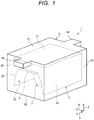
- the accommodation case 6 is formed of resins or the like. As shown in Fig. 1 , the accommodation case 6 includes an upper wall 61, a lower wall 62, and side walls 63 provided between the upper wall 61 and the lower wall 62.
- the accommodation case 6 is formed in a hollow box shape in which the magnetic body 3 can be accommodated.
- the upper wall 61 covers the upper wall 31 of the magnetic body 3.
- the lower wall 62 sandwiches the magnetic body 3 with the upper wall 61, i.e., the magnetic body 3 is disposed between the lower wall 62 and the upper wall 61.
- the side walls 63 cover both sides of the magnetic body 3 in the width direction X and the front-rear direction Y.
- the upper wall 61 is provided with attaching stays 64 protruding on both sides in the front-rear direction Y.
- the attaching stays 64 are to be attached to the ceiling R of the vehicle 7 by screwing or the like.
- the antenna module 1 described above is to be attached to the ceiling R of the vehicle.
- the antenna module 1 is attached to a center of the ceiling R in the width direction X (between a driver seat SH1 and a passenger seat SH2).
- the upper wall 61 and the attaching stays 64 of the accommodation case 6 contact the ceiling R, and the attaching stays 64 are attached thereto by being screwed.
- the antenna module 1 is disposed such that the longitudinal direction of the groove 33 (axial direction of the coil 22) is along the front-rear direction Y of the vehicle 7.
- a magnetic field H exiting from one end in the axial direction (front-rear direction Y) of the coil 22 toward the other end, is generated in the coil 22.
- the axial length of the coil 22 is set such that the strength of the magnetic field H does not exceed the extent at which the magnetic field H that can be received by the smart key outside the vehicle 7 does not leak outside a front window W2 and a rear window W3.
- the vertical walls 32 of the magnetic body 3 are disposed side by side in the width direction X of the vehicle 7 as shown in Fig. 7 .
- the magnetic body 3 absorbs a magnetic field from the LF antenna 2. Therefore, magnetic fields directed toward side windows W1 among magnetic fields generated by the LF antenna 2 are absorbed by the magnetic body 3, and thus do not reach side windows W1 in the width direction X of the vehicle 7.
- the magnetic body 3 shields magnetic fields generated by the LF antenna 2 and directed toward the side windows W1, and thus, dead-zone areas A1, where magnetic fields do not reach, are provided outside of the vertical walls 32 at both two sides of the vertical walls 32 in the width direction.
- the magnetic field can be prevented from leaking outside the side windows W1 even if the LF antenna 2 is disposed on the ceiling R, and erroneous detection that the smart key is in the vehicle 7 due to communication with the smart key outside the vehicle 7 can be prevented.
- the mounting space is less likely to be restricted by disposing the antenna module 1 on the ceiling R, as compared with the case where the antenna module 1 is disposed on the floor. Therefore, a plurality of small LF antennas are provided on the floor in the related art, due to restriction of the space, to form a magnetic field only in the vehicle 7.
- one large LF antenna 2 can be provided on the ceiling to form a magnetic field only in the vehicle 7 as shown in Fig. 1 .
- the LF antenna 2 is accommodated in the groove 33 such that the axial direction of the coil 22 intersects the facing direction of the pair of vertical walls 32, 32.
- the facing direction of the pair of vertical walls 32, 32 is disposed along the width direction X of the vehicle 7, the magnetic field directed along a direction intersecting the axial direction of the coil 22 toward the side windows W1 can be shielded by the pair of vertical walls 32, 32.
- the driver 4 is also provided on the ceiling R integrally with the LF antenna 2. Therefore, it is not necessary to connect the driver 4 to the LF antenna 2 via the long wire harness 8, and the resonance point shift due to parasitic inductance of the wire harness 8 can be prevented. Therefore, improvement in sensitivity can be achieved by increasing the Q factor of the LF antenna 2, or antenna currents can be reduced by increasing dumping resistance Rd without changing the sensitivity. In addition, since the rectangular wave signal generated by the driver 4 is applied to the LF antenna 2 without passing through the wire harness 8, the radiation noise can be reduced.
- both ends of the coil 22 are connected to the substrate 5, and the substrate 5 is fixed to the inner surface of the groove 33.
- the LF antenna 2 is connected to the substrate 5 fixed to the magnetic body 3, in which the LF antenna 2 can be supported.
- the accommodation case 6 accommodating the LF antenna 2 and the magnetic body 3 is attached to the ceiling R.
- the antenna module 1 can be attached to the ceiling R by using the accommodation case 6.
- the LF antenna 2 is used for the keyless entry system, but the present invention is not limited thereto.
- the LF antenna 2 may be used for other communication systems performed only in the vehicle 7.
- the groove 33 provided in the magnetic body 3 is opened in the front-rear direction Y, but a pair of walls closing the opening in the front-rear direction Y may be provided so that the magnetic field generated by the LF antenna 2 and directed toward the front window W2 and the rear window W3 can be shielded by the pair of walls.
- the shape of the magnetic body 3 is not limited to the above embodiment, and any shape that can shield the magnetic field from the LF antenna 2 toward the side windows W1 of the vehicle 7 may be used.
- the driver 4 is provided on the side of antenna module 1, but the present invention is not limited thereto. Similarly to the keyless entry device 9, the driver 4 may be disposed in an instrument panel of the vehicle 7.
- an antenna module (1) configured to be attached to a ceiling (R) of a vehicle (7), the antenna module (1)includes an antenna (2) and a magnetic body (3) including a pair of walls (32, 32) spaced apart from each other.
- the antenna (2) is accommodated between the pair of walls (32, 32).
- the magnetic body (3) may be disposed on the ceiling (R) of the vehicle (7) such that the magnetic body (3) shields a magnetic field generated by the antenna (2) and directed toward a window of the vehicle (7).
- the pair of walls shield the magnetic field generated by the antenna and directed toward the window of the vehicle, so that the magnetic field can be prevented from leaking outside the window even if the antenna is disposed on the ceiling.
- the antenna (2) may include a coil (22) spirally wound, the antenna (2) being accommodated between the pair of walls (32, 32) such that an axial direction (Y) of the coil (22) intersects a facing direction (X) in which the pair of walls (32, 32) face each other.
- the antenna is accommodated such that the axial direction of the coil intersects the facing direction of the pair of walls.
- the magnetic field directed along the direction intersecting the axial direction of the coil toward the window can be shielded by the pair of walls.
- the antenna module (1) may further include a driver (4) configured to drive the antenna (2).
- the driver is also provided on the ceiling integrally with the antenna. Therefore, it is not necessary to connect the driver to the antenna via a long wire harness, and the resonance point shift due to parasitic inductance of the wire harness can be prevented.
- the antenna module (1) may further include a driver (4) configured to drive the antenna (2) and a substrate (5) on which the driver (4) is mounted.
- the substrate (5) may be disposed between the pair of walls (32, 32) and may be fixed to the magnetic body (3), and the antenna (2) may be electrically connected to and fixed to the substrate (5).
- the antenna is connected to the substrate fixed to the magnetic body, so that the antenna can be supported.
- the antenna module (1) may further include an accommodation case (6) configured to accommodate the antenna (2) and the magnetic body (3).
- the accommodation case (6) may be to be attached to the ceiling (R).
- the antenna module can be attached to the ceiling using the accommodation case.
- the magnetic body (3) may include another pair of walls spaced apart from each other.
- the antenna (2) may be accommodated between the another pair of walls such that the axial direction (Y) of the coil (22) is parallel to a facing direction in which the another pair of walls face each other.
- the antenna is accommodated such that the axial direction of the coil is parallel to the facing direction of the another pair of walls.
- the magnetic field directed along the axial direction of the coil toward a window can be shielded by the another pair of walls.
Landscapes
- Engineering & Computer Science (AREA)
- Remote Sensing (AREA)
- Physics & Mathematics (AREA)
- Electromagnetism (AREA)
- Computer Security & Cryptography (AREA)
- Radar, Positioning & Navigation (AREA)
- Computer Networks & Wireless Communication (AREA)
- Signal Processing (AREA)
- Details Of Aerials (AREA)
- Support Of Aerials (AREA)
- Fittings On The Vehicle Exterior For Carrying Loads, And Devices For Holding Or Mounting Articles (AREA)
Abstract
Description
- The present invention relates to an antenna module to be mounted on a vehicle.
- A related art antenna is mounted on a vehicle and communicates with a communication terminal such as a smart key (see, for example,
JP 2013-70545 A JP 2002-46541 A - However, there are many factors that restrict spaces to mount the antenna on the floor, such as seats and the like on the floor of the vehicle. Therefore, it is also conceivable to dispose the antenna on a ceiling. However, since the ceiling is close to the window, the magnetic field may leak out of the vehicle through the window when the antenna is disposed on the ceiling, resulting in erroneous communication.
- Illustrative aspects of the present invention provide an antenna module configured to prevent leakage of a magnetic field outside a window even if an antenna is disposed on a ceiling.
- According to an illustrative aspect of the present invention, an antenna module configured to be attached to a ceiling of a vehicle includes an antenna and a magnetic body including a pair of walls spaced apart from each other. The antenna is accommodated between the pair of walls.
- Other aspects and advantages of the invention will be apparent from the following description, the drawings and the claims.
-
-
Fig. 1 is a perspective view showing an appearance of an antenna module of the present invention; -
Fig. 2 is a perspective view of the antenna module from which an accommodation case shown inFig. 1 is removed; -
Fig. 3 is a perspective view of the antenna module from which a magnetic body and a substrate shown inFig. 2 are removed; -
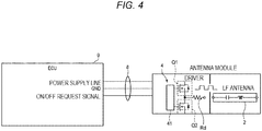
Fig. 4 is a diagram showing an electrical configuration of the antenna module shown inFigs. 1 to 3 ; -
Fig. 5 is a time chart showing outputs of an ECU and a driver shown inFig. 4 ; -
Fig. 6 is a schematic side view of a vehicle to which the antenna module shown inFigs. 1 to 3 is attached; -
Fig. 7 is a sectional view taken along a line I-I ofFig. 6 ; and -
Fig. 8 is a schematic top view of a vehicle to which the antenna module shown inFigs. 1 to 3 is attached. - Specific embodiments of the present invention will be described below with reference to the drawings.
- As shown in
Figs. 6 to 8 , anantenna module 1 of the present embodiment is attached to a ceiling R of avehicle 7 and is used for, for example, a keyless entry system. The keyless entry system is a system that locks and unlocks a door if locking operation or unlocking operation of the door is detected when a smart key is in the vicinity of thevehicle 7. The keyless entry system has a function of notifying that the smart key is left in thevehicle 7 when the smart key is actually left in thevehicle 7 while the locking operation of the door is performed. Theantenna module 1 of the present embodiment is used to detect whether a smart key is in thevehicle 7. - In the keyless entry system, the
antenna module 1 transmits an LF signal to a smart key. Theantenna module 1 forms a magnetic field only withn thevehicle 7 so that the LF signal can be received by a smart key in thevehicle 7 but not by a smart key outside thevehicle 7. The smart key transmits an RF signal when receiving the LF signal, and an RF antenna (not shown) provided in thevehicle 7 receives the RF signal. At this time, theantenna module 1 detects a smart key left in thevehicle 7. - The configuration of the
antenna module 1 will be described with reference toFigs. 1 to 3 . X in the drawings indicates a width direction of thevehicle 7, Y indicates a front-rear direction of thevehicle 7, and Z indicates an upper-lower direction of thevehicle 7. As shown inFigs. 1 to 3 , theantenna module 1 includes a LF antenna 2 (antenna), amagnetic body 3 for shielding a magnetic field generated by theLF antenna 2 and directed toward a side window (window) W1 (shown inFig. 8 ) of thevehicle 7, asubstrate 5 on which a driver 4 configured to drive theLF antenna 2, or the like is mounted, and anaccommodation case 6 for accommodating theseLF antenna 2, themagnetic body 3, and thesubstrate 5. - The
LF antenna 2 of the present embodiment transmits an LF signal in a LF band. As shown inFig. 3 , theLF antenna 2 includes amagnetic core 21 having a columnar shape and acoil 22 spirally winds around themagnetic core 21. - As shown in
Fig. 2 , themagnetic body 3 includes anupper wall 31 extending longer in the front-rear direction Y than the width direction X and a pair of vertical walls (walls) 32, 32 extending downward from both ends of theupper wall 31 in the width direction X, and agroove 33 extending continuously from one end to the other end in the front-rear direction Y of themagnetic body 3 is formed. The pair ofvertical walls groove 33 are long in the front-rear direction (longitudinal direction) Y. Thegroove 33 opens downward and at both sides in the front-rear direction Y of themagnetic body 3. Thegroove 33 is closed by theupper wall 31, i.e. the groove has theupper wall 31 as its bottom. Thegroove 33 has a cross section of semicircular shape in which a vertex of the semicircular shape is flattened continuously from the one end to the other end in the front-rear direction Y. - That is, an upper surface (bottom) of the
groove 33 is flat, and an inner surface thereof is formed in a curved surface such that the width of thegroove 33 decreases toward the upper surface, i.e., the width of thegroove 33 increases downward. TheLF antenna 2 is accommodated in thegroove 33 provided between the pair ofvertical walls LF antenna 2 is accommodated between the pair ofvertical walls vertical walls Fig. 7 , theLF antenna 2 does not extend beyond a lower opening of thegroove 33 to the outside of thegroove 33, and theentire LF antenna 2 is accommodated in thegroove 33. - The
coil 22 shown inFig. 3 is spirally wound around themagnetic core 21. - A resonance capacitor (not shown) forming a resonance circuit together with the
coil 22, and the driver 4 for driving theLF antenna 2 are mounted on thesubstrate 5. As shown inFig. 4 , the driver 4 includes two FETs Q1, Q2 connected in series, and agate drive circuit 41 for driving the two FETs Q1, Q2 on and off. The driver 4 is connected to a keyless entry device 9, which includes an ECU disposed in an instrument panel of thevehicle 7, via a wire harness 8. - A power supply line, a ground line, and an ON/OFF request signal line are included in the wire harness 8, and power supply and an ON-OFF request signal are supplied to the driver 4 from the keyless entry device 9 through the wire harness 8. As shown in
Fig. 5 , the keyless entry device 9 outputs a Hi-level ON request signal requesting ON and a Lo-level OFF request signal requesting OFF. When the ON request signal is input, thegate drive circuit 41 controls ON/OFF of the two FETs Q1, Q2 in the opposite phase (exclusively) to generate a rectangular wave signal (shown inFig. 5 ) from the power supply. The rectangular wave signal is applied to a primary coil via dump resistance Rd. As a result, a sinusoidal resonant current is generated in a secondary coil, and an alternating magnetic field is generated in a predetermined space. - As shown in
Fig. 2 , thesubstrate 5 is formed in a rectangular shape extending longer in the front-rear direction Y than in the width direction X and is fixed to the flat upper surface (bottom) of thegroove 33 of themagnetic body 3 by a locking claw or a screw. As a result, thesubstrate 5 is disposed between the pair ofvertical walls LF antenna 2 is disposed on a lower side of thesubstrate 5. Both ends of thecoil 22 of theLF antenna 2 are connected to thesubstrate 5 by soldering, connector connection, or the like. As a result, theLF antenna 2 is electrically connected to thesubstrate 5 and is fixed onto thesubstrate 5. - The
accommodation case 6 is formed of resins or the like. As shown inFig. 1 , theaccommodation case 6 includes anupper wall 61, alower wall 62, andside walls 63 provided between theupper wall 61 and thelower wall 62. Theaccommodation case 6 is formed in a hollow box shape in which themagnetic body 3 can be accommodated. Theupper wall 61 covers theupper wall 31 of themagnetic body 3. Thelower wall 62 sandwiches themagnetic body 3 with theupper wall 61, i.e., themagnetic body 3 is disposed between thelower wall 62 and theupper wall 61. Theside walls 63 cover both sides of themagnetic body 3 in the width direction X and the front-rear direction Y. Theupper wall 61 is provided with attachingstays 64 protruding on both sides in the front-rear direction Y. The attaching stays 64 are to be attached to the ceiling R of thevehicle 7 by screwing or the like. - Next, the arrangement of the
antenna module 1 will be described. As shown inFigs. 6 and7 , theantenna module 1 described above is to be attached to the ceiling R of the vehicle. In the present embodiment, theantenna module 1 is attached to a center of the ceiling R in the width direction X (between a driver seat SH1 and a passenger seat SH2). Specifically, theupper wall 61 and the attaching stays 64 of theaccommodation case 6 contact the ceiling R, and the attaching stays 64 are attached thereto by being screwed. At this time, theantenna module 1 is disposed such that the longitudinal direction of the groove 33 (axial direction of the coil 22) is along the front-rear direction Y of thevehicle 7. - As shown in
Fig. 8 , a magnetic field H, exiting from one end in the axial direction (front-rear direction Y) of thecoil 22 toward the other end, is generated in thecoil 22. The axial length of thecoil 22 is set such that the strength of the magnetic field H does not exceed the extent at which the magnetic field H that can be received by the smart key outside thevehicle 7 does not leak outside a front window W2 and a rear window W3. - When the longitudinal direction of the
groove 33 is arranged along the front-rear direction Y of thevehicle 7 as described above, thevertical walls 32 of themagnetic body 3 are disposed side by side in the width direction X of thevehicle 7 as shown inFig. 7 . Themagnetic body 3 absorbs a magnetic field from theLF antenna 2. Therefore, magnetic fields directed toward side windows W1 among magnetic fields generated by theLF antenna 2 are absorbed by themagnetic body 3, and thus do not reach side windows W1 in the width direction X of thevehicle 7. - That is, the
magnetic body 3 shields magnetic fields generated by theLF antenna 2 and directed toward the side windows W1, and thus, dead-zone areas A1, where magnetic fields do not reach, are provided outside of thevertical walls 32 at both two sides of thevertical walls 32 in the width direction. As a result, the magnetic field can be prevented from leaking outside the side windows W1 even if theLF antenna 2 is disposed on the ceiling R, and erroneous detection that the smart key is in thevehicle 7 due to communication with the smart key outside thevehicle 7 can be prevented. - The mounting space is less likely to be restricted by disposing the
antenna module 1 on the ceiling R, as compared with the case where theantenna module 1 is disposed on the floor. Therefore, a plurality of small LF antennas are provided on the floor in the related art, due to restriction of the space, to form a magnetic field only in thevehicle 7. However, according to the present embodiment, onelarge LF antenna 2 can be provided on the ceiling to form a magnetic field only in thevehicle 7 as shown inFig. 1 . - According to the embodiment described above, the
LF antenna 2 is accommodated in thegroove 33 such that the axial direction of thecoil 22 intersects the facing direction of the pair ofvertical walls vertical walls vehicle 7, the magnetic field directed along a direction intersecting the axial direction of thecoil 22 toward the side windows W1 can be shielded by the pair ofvertical walls - According to the embodiment described above, the driver 4 is also provided on the ceiling R integrally with the
LF antenna 2. Therefore, it is not necessary to connect the driver 4 to theLF antenna 2 via the long wire harness 8, and the resonance point shift due to parasitic inductance of the wire harness 8 can be prevented. Therefore, improvement in sensitivity can be achieved by increasing the Q factor of theLF antenna 2, or antenna currents can be reduced by increasing dumping resistance Rd without changing the sensitivity. In addition, since the rectangular wave signal generated by the driver 4 is applied to theLF antenna 2 without passing through the wire harness 8, the radiation noise can be reduced. - According to the embodiment described above, both ends of the
coil 22 are connected to thesubstrate 5, and thesubstrate 5 is fixed to the inner surface of thegroove 33. As a result, theLF antenna 2 is connected to thesubstrate 5 fixed to themagnetic body 3, in which theLF antenna 2 can be supported. - According to the embodiment described above, the
accommodation case 6 accommodating theLF antenna 2 and themagnetic body 3 is attached to the ceiling R. As a result, theantenna module 1 can be attached to the ceiling R by using theaccommodation case 6. - While the present invention has been described with reference to certain exemplary embodiments thereof, the scope of the present invention is not limited to the exemplary embodiments described above, and it will be understood by those skilled in the art that various changes and modifications may be made therein without departing from the scope of the present invention as defined by the appended claims.
- According to the embodiment described above, the
LF antenna 2 is used for the keyless entry system, but the present invention is not limited thereto. TheLF antenna 2 may be used for other communication systems performed only in thevehicle 7. - According to the embodiment described above, the
groove 33 provided in themagnetic body 3 is opened in the front-rear direction Y, but a pair of walls closing the opening in the front-rear direction Y may be provided so that the magnetic field generated by theLF antenna 2 and directed toward the front window W2 and the rear window W3 can be shielded by the pair of walls. - The shape of the
magnetic body 3 is not limited to the above embodiment, and any shape that can shield the magnetic field from theLF antenna 2 toward the side windows W1 of thevehicle 7 may be used. - Further, according to the embodiment described above, the driver 4 is provided on the side of
antenna module 1, but the present invention is not limited thereto. Similarly to the keyless entry device 9, the driver 4 may be disposed in an instrument panel of thevehicle 7. - According to an aspect of the embodiments described above, an antenna module (1) configured to be attached to a ceiling (R) of a vehicle (7), the antenna module (1)includes an antenna (2) and a magnetic body (3) including a pair of walls (32, 32) spaced apart from each other. The antenna (2) is accommodated between the pair of walls (32, 32).
- The magnetic body (3) may be disposed on the ceiling (R) of the vehicle (7) such that the magnetic body (3) shields a magnetic field generated by the antenna (2) and directed toward a window of the vehicle (7).
- According to the antenna module having the above configuration, the pair of walls shield the magnetic field generated by the antenna and directed toward the window of the vehicle, so that the magnetic field can be prevented from leaking outside the window even if the antenna is disposed on the ceiling.
- The antenna (2) may include a coil (22) spirally wound, the antenna (2) being accommodated between the pair of walls (32, 32) such that an axial direction (Y) of the coil (22) intersects a facing direction (X) in which the pair of walls (32, 32) face each other.
- According to the antenna module having the above configuration, the antenna is accommodated such that the axial direction of the coil intersects the facing direction of the pair of walls. As a result, the magnetic field directed along the direction intersecting the axial direction of the coil toward the window can be shielded by the pair of walls.
- The antenna module (1) may further include a driver (4) configured to drive the antenna (2).
- According to the antenna module having the above configuration, the driver is also provided on the ceiling integrally with the antenna. Therefore, it is not necessary to connect the driver to the antenna via a long wire harness, and the resonance point shift due to parasitic inductance of the wire harness can be prevented.
- The antenna module (1) may further include a driver (4) configured to drive the antenna (2) and a substrate (5) on which the driver (4) is mounted. The substrate (5) may be disposed between the pair of walls (32, 32) and may be fixed to the magnetic body (3), and the antenna (2) may be electrically connected to and fixed to the substrate (5).
- According to the antenna module having the above configuration, the antenna is connected to the substrate fixed to the magnetic body, so that the antenna can be supported.
- The antenna module (1) may further include an accommodation case (6) configured to accommodate the antenna (2) and the magnetic body (3). The accommodation case (6) may be to be attached to the ceiling (R).
- According to the antenna module having the above configuration, the antenna module can be attached to the ceiling using the accommodation case.
- The magnetic body (3) may include another pair of walls spaced apart from each other. The antenna (2) may be accommodated between the another pair of walls such that the axial direction (Y) of the coil (22) is parallel to a facing direction in which the another pair of walls face each other.
- According to the antenna module having the above configuration, the antenna is accommodated such that the axial direction of the coil is parallel to the facing direction of the another pair of walls. As a result, the magnetic field directed along the axial direction of the coil toward a window can be shielded by the another pair of walls.
Claims (7)
- An antenna module configured to be attached to a ceiling of a vehicle, the antenna module comprising:an antenna; anda magnetic body including a pair of walls spaced apart from each other,wherein the antenna is accommodated between the pair of walls.
- The antenna module according to claim 1,
wherein the magnetic body is disposed on the ceiling of the vehicle such that the magnetic body shields a magnetic field generated by the antenna and directed toward a window of the vehicle. - The antenna module according to claim 1 or 2,
wherein the antenna includes a coil spirally wound, the antenna being accommodated between the pair of walls such that an axial direction of the coil intersects a facing direction in which the pair of walls face each other. - The antenna module according to any one of claims 1 to 3, further comprising:
a driver configured to drive the antenna. - The antenna module according to any one of claims 1 to 3, further comprising:a driver configured to drive the antenna; anda substrate on which the driver is mounted,wherein the substrate is disposed between the pair of walls and is fixed to the magnetic body, andwherein the antenna is electrically connected to and fixed to the substrate.
- The antenna module according to any one of claims 1 to 5, further comprising:an accommodation case configured to accommodate the antenna and the magnetic body,wherein the accommodation case is to be attached to the ceiling.
- The antenna module according to claims 3
wherein the magnetic body includes another pair of walls spaced apart from each other, and
wherein the antenna is accommodated between the another pair of walls such that the axial direction of the coil is parallel to a facing direction in which the another pair of walls face each other.
Applications Claiming Priority (1)
| Application Number | Priority Date | Filing Date | Title |
|---|---|---|---|
| JP2019133782A JP7051761B2 (en) | 2019-07-19 | 2019-07-19 | Antenna module |
Publications (2)
| Publication Number | Publication Date |
|---|---|
| EP3767835A1 true EP3767835A1 (en) | 2021-01-20 |
| EP3767835B1 EP3767835B1 (en) | 2023-03-15 |
Family
ID=71409225
Family Applications (1)
| Application Number | Title | Priority Date | Filing Date |
|---|---|---|---|
| EP20183229.2A Active EP3767835B1 (en) | 2019-07-19 | 2020-06-30 | Antenna module |
Country Status (4)
| Country | Link |
|---|---|
| US (1) | US11335998B2 (en) |
| EP (1) | EP3767835B1 (en) |
| JP (1) | JP7051761B2 (en) |
| CN (1) | CN112242608B (en) |
Families Citing this family (2)
| Publication number | Priority date | Publication date | Assignee | Title |
|---|---|---|---|---|
| CN117581424A (en) * | 2021-07-19 | 2024-02-20 | 株式会社友华 | Antenna device |
| KR20250090973A (en) * | 2023-12-13 | 2025-06-20 | 현대자동차주식회사 | Apparatus for controlling a vehicle and method thereof |
Citations (6)
| Publication number | Priority date | Publication date | Assignee | Title |
|---|---|---|---|---|
| WO1999063617A1 (en) * | 1998-06-05 | 1999-12-09 | Smarteq Ab | Integrated antenna means for a motor vehicle comprising reflector |
| JP2002046541A (en) | 2000-08-04 | 2002-02-12 | Omron Corp | Control device |
| JP2010222841A (en) * | 2009-03-24 | 2010-10-07 | Nissan Motor Co Ltd | Vehicle locking and unlocking device |
| JP2013070545A (en) | 2011-09-26 | 2013-04-18 | Honda Motor Co Ltd | Wireless power transmission apparatus and on vehicle system using the same |
| US20150145646A1 (en) * | 2013-11-27 | 2015-05-28 | Alps Electric Co., Ltd. | Keyless entry system |
| DE102016121335A1 (en) * | 2016-11-08 | 2018-05-09 | Epcos Ag | Magnetic antenna with reduced losses and use thereof |
Family Cites Families (5)
| Publication number | Priority date | Publication date | Assignee | Title |
|---|---|---|---|---|
| EP1689029B1 (en) | 2003-11-27 | 2016-10-05 | Hitachi Metals, Ltd. | Antenna and radio timepiece using the same, keyless entry system, and rf id system |
| JP4592001B2 (en) | 2003-12-11 | 2010-12-01 | 日立金属株式会社 | Antenna, radio clock using the same, keyless entry system, RFID system |
| JP6074744B2 (en) * | 2011-04-22 | 2017-02-08 | パナソニックIpマネジメント株式会社 | In-vehicle charger and vehicle equipped with the same |
| JP2015047013A (en) | 2013-08-28 | 2015-03-12 | トヨタ自動車株式会社 | Power receiving device, power transmitting device, and vehicle |
| JP2018021385A (en) | 2016-08-04 | 2018-02-08 | カルソニックカンセイ株式会社 | Keyless entry system and vehicle inside-outside determination method |
-
2019
- 2019-07-19 JP JP2019133782A patent/JP7051761B2/en not_active Expired - Fee Related
-
2020
- 2020-06-30 EP EP20183229.2A patent/EP3767835B1/en active Active
- 2020-07-14 CN CN202010675995.7A patent/CN112242608B/en active Active
- 2020-07-15 US US16/929,729 patent/US11335998B2/en active Active
Patent Citations (6)
| Publication number | Priority date | Publication date | Assignee | Title |
|---|---|---|---|---|
| WO1999063617A1 (en) * | 1998-06-05 | 1999-12-09 | Smarteq Ab | Integrated antenna means for a motor vehicle comprising reflector |
| JP2002046541A (en) | 2000-08-04 | 2002-02-12 | Omron Corp | Control device |
| JP2010222841A (en) * | 2009-03-24 | 2010-10-07 | Nissan Motor Co Ltd | Vehicle locking and unlocking device |
| JP2013070545A (en) | 2011-09-26 | 2013-04-18 | Honda Motor Co Ltd | Wireless power transmission apparatus and on vehicle system using the same |
| US20150145646A1 (en) * | 2013-11-27 | 2015-05-28 | Alps Electric Co., Ltd. | Keyless entry system |
| DE102016121335A1 (en) * | 2016-11-08 | 2018-05-09 | Epcos Ag | Magnetic antenna with reduced losses and use thereof |
Also Published As
| Publication number | Publication date |
|---|---|
| JP2021019280A (en) | 2021-02-15 |
| US11335998B2 (en) | 2022-05-17 |
| US20210021022A1 (en) | 2021-01-21 |
| CN112242608A (en) | 2021-01-19 |
| JP7051761B2 (en) | 2022-04-11 |
| CN112242608B (en) | 2023-11-24 |
| EP3767835B1 (en) | 2023-03-15 |
Similar Documents
| Publication | Publication Date | Title |
|---|---|---|
| CN113767205B (en) | Position determination system | |
| KR101750149B1 (en) | Vehicle | |
| EP3767835B1 (en) | Antenna module | |
| US20010026244A1 (en) | Loop antenna device | |
| US20050159131A1 (en) | Communicator and vehicle controller | |
| US11574770B2 (en) | Coil unit | |
| CN113939636B (en) | Position determination system | |
| KR20150003894A (en) | Power reception device, power transmission device, and vehicle | |
| US6756945B2 (en) | Antenna structure for vehicle | |
| JP2009532600A (en) | Auto locking system for automobile | |
| JP5088026B2 (en) | Smart keyless entry system | |
| US11731586B2 (en) | Locking and unlocking module and door handle module | |
| US10412865B2 (en) | Vehicle electrical apparatus | |
| JP6024565B2 (en) | Power supply device and power transmission unit of power supply device | |
| BRPI0413273B1 (en) | vehicle glass antenna | |
| US20240322423A1 (en) | Antenna device | |
| US20170285209A1 (en) | Device for the contactless actuation of an adjustable vehicle part | |
| US7403168B2 (en) | Antenna device and communications system using the same | |
| JP2002370584A (en) | Vehicle door with built-in antenna | |
| JP2001303819A (en) | Keyless entry device for automobile | |
| JP2004534487A (en) | Automotive identification device | |
| JP2004247854A (en) | Remote control system |
Legal Events
| Date | Code | Title | Description |
|---|---|---|---|
| PUAI | Public reference made under article 153(3) epc to a published international application that has entered the european phase |
Free format text: ORIGINAL CODE: 0009012 |
|
| STAA | Information on the status of an ep patent application or granted ep patent |
Free format text: STATUS: REQUEST FOR EXAMINATION WAS MADE |
|
| 17P | Request for examination filed |
Effective date: 20200630 |
|
| AK | Designated contracting states |
Kind code of ref document: A1 Designated state(s): AL AT BE BG CH CY CZ DE DK EE ES FI FR GB GR HR HU IE IS IT LI LT LU LV MC MK MT NL NO PL PT RO RS SE SI SK SM TR |
|
| AX | Request for extension of the european patent |
Extension state: BA ME |
|
| STAA | Information on the status of an ep patent application or granted ep patent |
Free format text: STATUS: EXAMINATION IS IN PROGRESS |
|
| 17Q | First examination report despatched |
Effective date: 20211216 |
|
| GRAP | Despatch of communication of intention to grant a patent |
Free format text: ORIGINAL CODE: EPIDOSNIGR1 |
|
| STAA | Information on the status of an ep patent application or granted ep patent |
Free format text: STATUS: GRANT OF PATENT IS INTENDED |
|
| INTG | Intention to grant announced |
Effective date: 20221220 |
|
| GRAS | Grant fee paid |
Free format text: ORIGINAL CODE: EPIDOSNIGR3 |
|
| GRAA | (expected) grant |
Free format text: ORIGINAL CODE: 0009210 |
|
| STAA | Information on the status of an ep patent application or granted ep patent |
Free format text: STATUS: THE PATENT HAS BEEN GRANTED |
|
| AK | Designated contracting states |
Kind code of ref document: B1 Designated state(s): AL AT BE BG CH CY CZ DE DK EE ES FI FR GB GR HR HU IE IS IT LI LT LU LV MC MK MT NL NO PL PT RO RS SE SI SK SM TR |
|
| REG | Reference to a national code |
Ref country code: CH Ref legal event code: EP Ref country code: GB Ref legal event code: FG4D |
|
| REG | Reference to a national code |
Ref country code: DE Ref legal event code: R096 Ref document number: 602020008819 Country of ref document: DE |
|
| REG | Reference to a national code |
Ref country code: IE Ref legal event code: FG4D |
|
| REG | Reference to a national code |
Ref country code: AT Ref legal event code: REF Ref document number: 1554578 Country of ref document: AT Kind code of ref document: T Effective date: 20230415 |
|
| RAP4 | Party data changed (patent owner data changed or rights of a patent transferred) |
Owner name: YAZAKI CORPORATION |
|
| REG | Reference to a national code |
Ref country code: LT Ref legal event code: MG9D |
|
| REG | Reference to a national code |
Ref country code: NL Ref legal event code: MP Effective date: 20230315 |
|
| PG25 | Lapsed in a contracting state [announced via postgrant information from national office to epo] |
Ref country code: RS Free format text: LAPSE BECAUSE OF FAILURE TO SUBMIT A TRANSLATION OF THE DESCRIPTION OR TO PAY THE FEE WITHIN THE PRESCRIBED TIME-LIMIT Effective date: 20230315 Ref country code: NO Free format text: LAPSE BECAUSE OF FAILURE TO SUBMIT A TRANSLATION OF THE DESCRIPTION OR TO PAY THE FEE WITHIN THE PRESCRIBED TIME-LIMIT Effective date: 20230615 Ref country code: LV Free format text: LAPSE BECAUSE OF FAILURE TO SUBMIT A TRANSLATION OF THE DESCRIPTION OR TO PAY THE FEE WITHIN THE PRESCRIBED TIME-LIMIT Effective date: 20230315 Ref country code: LT Free format text: LAPSE BECAUSE OF FAILURE TO SUBMIT A TRANSLATION OF THE DESCRIPTION OR TO PAY THE FEE WITHIN THE PRESCRIBED TIME-LIMIT Effective date: 20230315 Ref country code: HR Free format text: LAPSE BECAUSE OF FAILURE TO SUBMIT A TRANSLATION OF THE DESCRIPTION OR TO PAY THE FEE WITHIN THE PRESCRIBED TIME-LIMIT Effective date: 20230315 |
|
| PGFP | Annual fee paid to national office [announced via postgrant information from national office to epo] |
Ref country code: DE Payment date: 20230502 Year of fee payment: 4 |
|
| REG | Reference to a national code |
Ref country code: AT Ref legal event code: MK05 Ref document number: 1554578 Country of ref document: AT Kind code of ref document: T Effective date: 20230315 |
|
| PG25 | Lapsed in a contracting state [announced via postgrant information from national office to epo] |
Ref country code: SE Free format text: LAPSE BECAUSE OF FAILURE TO SUBMIT A TRANSLATION OF THE DESCRIPTION OR TO PAY THE FEE WITHIN THE PRESCRIBED TIME-LIMIT Effective date: 20230315 Ref country code: NL Free format text: LAPSE BECAUSE OF FAILURE TO SUBMIT A TRANSLATION OF THE DESCRIPTION OR TO PAY THE FEE WITHIN THE PRESCRIBED TIME-LIMIT Effective date: 20230315 Ref country code: GR Free format text: LAPSE BECAUSE OF FAILURE TO SUBMIT A TRANSLATION OF THE DESCRIPTION OR TO PAY THE FEE WITHIN THE PRESCRIBED TIME-LIMIT Effective date: 20230616 Ref country code: FI Free format text: LAPSE BECAUSE OF FAILURE TO SUBMIT A TRANSLATION OF THE DESCRIPTION OR TO PAY THE FEE WITHIN THE PRESCRIBED TIME-LIMIT Effective date: 20230315 |
|
| PG25 | Lapsed in a contracting state [announced via postgrant information from national office to epo] |
Ref country code: SM Free format text: LAPSE BECAUSE OF FAILURE TO SUBMIT A TRANSLATION OF THE DESCRIPTION OR TO PAY THE FEE WITHIN THE PRESCRIBED TIME-LIMIT Effective date: 20230315 Ref country code: RO Free format text: LAPSE BECAUSE OF FAILURE TO SUBMIT A TRANSLATION OF THE DESCRIPTION OR TO PAY THE FEE WITHIN THE PRESCRIBED TIME-LIMIT Effective date: 20230315 Ref country code: PT Free format text: LAPSE BECAUSE OF FAILURE TO SUBMIT A TRANSLATION OF THE DESCRIPTION OR TO PAY THE FEE WITHIN THE PRESCRIBED TIME-LIMIT Effective date: 20230717 Ref country code: ES Free format text: LAPSE BECAUSE OF FAILURE TO SUBMIT A TRANSLATION OF THE DESCRIPTION OR TO PAY THE FEE WITHIN THE PRESCRIBED TIME-LIMIT Effective date: 20230315 Ref country code: EE Free format text: LAPSE BECAUSE OF FAILURE TO SUBMIT A TRANSLATION OF THE DESCRIPTION OR TO PAY THE FEE WITHIN THE PRESCRIBED TIME-LIMIT Effective date: 20230315 Ref country code: CZ Free format text: LAPSE BECAUSE OF FAILURE TO SUBMIT A TRANSLATION OF THE DESCRIPTION OR TO PAY THE FEE WITHIN THE PRESCRIBED TIME-LIMIT Effective date: 20230315 Ref country code: AT Free format text: LAPSE BECAUSE OF FAILURE TO SUBMIT A TRANSLATION OF THE DESCRIPTION OR TO PAY THE FEE WITHIN THE PRESCRIBED TIME-LIMIT Effective date: 20230315 |
|
| PG25 | Lapsed in a contracting state [announced via postgrant information from national office to epo] |
Ref country code: SK Free format text: LAPSE BECAUSE OF FAILURE TO SUBMIT A TRANSLATION OF THE DESCRIPTION OR TO PAY THE FEE WITHIN THE PRESCRIBED TIME-LIMIT Effective date: 20230315 Ref country code: PL Free format text: LAPSE BECAUSE OF FAILURE TO SUBMIT A TRANSLATION OF THE DESCRIPTION OR TO PAY THE FEE WITHIN THE PRESCRIBED TIME-LIMIT Effective date: 20230315 Ref country code: IS Free format text: LAPSE BECAUSE OF FAILURE TO SUBMIT A TRANSLATION OF THE DESCRIPTION OR TO PAY THE FEE WITHIN THE PRESCRIBED TIME-LIMIT Effective date: 20230715 |
|
| REG | Reference to a national code |
Ref country code: DE Ref legal event code: R097 Ref document number: 602020008819 Country of ref document: DE |
|
| PG25 | Lapsed in a contracting state [announced via postgrant information from national office to epo] |
Ref country code: MC Free format text: LAPSE BECAUSE OF FAILURE TO SUBMIT A TRANSLATION OF THE DESCRIPTION OR TO PAY THE FEE WITHIN THE PRESCRIBED TIME-LIMIT Effective date: 20230315 |
|
| PLBE | No opposition filed within time limit |
Free format text: ORIGINAL CODE: 0009261 |
|
| STAA | Information on the status of an ep patent application or granted ep patent |
Free format text: STATUS: NO OPPOSITION FILED WITHIN TIME LIMIT |
|
| PG25 | Lapsed in a contracting state [announced via postgrant information from national office to epo] |
Ref country code: SI Free format text: LAPSE BECAUSE OF FAILURE TO SUBMIT A TRANSLATION OF THE DESCRIPTION OR TO PAY THE FEE WITHIN THE PRESCRIBED TIME-LIMIT Effective date: 20230315 Ref country code: MC Free format text: LAPSE BECAUSE OF FAILURE TO SUBMIT A TRANSLATION OF THE DESCRIPTION OR TO PAY THE FEE WITHIN THE PRESCRIBED TIME-LIMIT Effective date: 20230315 Ref country code: DK Free format text: LAPSE BECAUSE OF FAILURE TO SUBMIT A TRANSLATION OF THE DESCRIPTION OR TO PAY THE FEE WITHIN THE PRESCRIBED TIME-LIMIT Effective date: 20230315 |
|
| REG | Reference to a national code |
Ref country code: CH Ref legal event code: PL |
|
| 26N | No opposition filed |
Effective date: 20231218 |
|
| REG | Reference to a national code |
Ref country code: BE Ref legal event code: MM Effective date: 20230630 |
|
| PG25 | Lapsed in a contracting state [announced via postgrant information from national office to epo] |
Ref country code: LU Free format text: LAPSE BECAUSE OF NON-PAYMENT OF DUE FEES Effective date: 20230630 |
|
| REG | Reference to a national code |
Ref country code: IE Ref legal event code: MM4A |
|
| PG25 | Lapsed in a contracting state [announced via postgrant information from national office to epo] |
Ref country code: LU Free format text: LAPSE BECAUSE OF NON-PAYMENT OF DUE FEES Effective date: 20230630 |
|
| PG25 | Lapsed in a contracting state [announced via postgrant information from national office to epo] |
Ref country code: IE Free format text: LAPSE BECAUSE OF NON-PAYMENT OF DUE FEES Effective date: 20230630 |
|
| PG25 | Lapsed in a contracting state [announced via postgrant information from national office to epo] |
Ref country code: IE Free format text: LAPSE BECAUSE OF NON-PAYMENT OF DUE FEES Effective date: 20230630 Ref country code: CH Free format text: LAPSE BECAUSE OF NON-PAYMENT OF DUE FEES Effective date: 20230630 |
|
| PG25 | Lapsed in a contracting state [announced via postgrant information from national office to epo] |
Ref country code: IT Free format text: LAPSE BECAUSE OF FAILURE TO SUBMIT A TRANSLATION OF THE DESCRIPTION OR TO PAY THE FEE WITHIN THE PRESCRIBED TIME-LIMIT Effective date: 20230315 Ref country code: FR Free format text: LAPSE BECAUSE OF NON-PAYMENT OF DUE FEES Effective date: 20230630 Ref country code: BE Free format text: LAPSE BECAUSE OF NON-PAYMENT OF DUE FEES Effective date: 20230630 |
|
| PG25 | Lapsed in a contracting state [announced via postgrant information from national office to epo] |
Ref country code: BG Free format text: LAPSE BECAUSE OF FAILURE TO SUBMIT A TRANSLATION OF THE DESCRIPTION OR TO PAY THE FEE WITHIN THE PRESCRIBED TIME-LIMIT Effective date: 20230315 |
|
| PG25 | Lapsed in a contracting state [announced via postgrant information from national office to epo] |
Ref country code: BG Free format text: LAPSE BECAUSE OF FAILURE TO SUBMIT A TRANSLATION OF THE DESCRIPTION OR TO PAY THE FEE WITHIN THE PRESCRIBED TIME-LIMIT Effective date: 20230315 |
|
| REG | Reference to a national code |
Ref country code: DE Ref legal event code: R119 Ref document number: 602020008819 Country of ref document: DE |
|
| GBPC | Gb: european patent ceased through non-payment of renewal fee |
Effective date: 20240630 |
|
| PG25 | Lapsed in a contracting state [announced via postgrant information from national office to epo] |
Ref country code: DE Free format text: LAPSE BECAUSE OF NON-PAYMENT OF DUE FEES Effective date: 20250101 |
|
| PG25 | Lapsed in a contracting state [announced via postgrant information from national office to epo] |
Ref country code: GB Free format text: LAPSE BECAUSE OF NON-PAYMENT OF DUE FEES Effective date: 20240630 |
|
| PG25 | Lapsed in a contracting state [announced via postgrant information from national office to epo] |
Ref country code: CY Free format text: LAPSE BECAUSE OF FAILURE TO SUBMIT A TRANSLATION OF THE DESCRIPTION OR TO PAY THE FEE WITHIN THE PRESCRIBED TIME-LIMIT; INVALID AB INITIO Effective date: 20200630 |
|
| PG25 | Lapsed in a contracting state [announced via postgrant information from national office to epo] |
Ref country code: HU Free format text: LAPSE BECAUSE OF FAILURE TO SUBMIT A TRANSLATION OF THE DESCRIPTION OR TO PAY THE FEE WITHIN THE PRESCRIBED TIME-LIMIT; INVALID AB INITIO Effective date: 20200630 |
|
| PG25 | Lapsed in a contracting state [announced via postgrant information from national office to epo] |
Ref country code: TR Free format text: LAPSE BECAUSE OF FAILURE TO SUBMIT A TRANSLATION OF THE DESCRIPTION OR TO PAY THE FEE WITHIN THE PRESCRIBED TIME-LIMIT Effective date: 20230315 |