EP3767760A1 - Optical relay, optical relay production method, and optical signal relay method - Google Patents
Optical relay, optical relay production method, and optical signal relay method Download PDFInfo
- Publication number
- EP3767760A1 EP3767760A1 EP18909278.6A EP18909278A EP3767760A1 EP 3767760 A1 EP3767760 A1 EP 3767760A1 EP 18909278 A EP18909278 A EP 18909278A EP 3767760 A1 EP3767760 A1 EP 3767760A1
- Authority
- EP
- European Patent Office
- Prior art keywords
- light
- optical
- lights
- branched
- output
- Prior art date
- Legal status (The legal status is an assumption and is not a legal conclusion. Google has not performed a legal analysis and makes no representation as to the accuracy of the status listed.)
- Granted
Links
Images






Classifications
-
- H—ELECTRICITY
- H04—ELECTRIC COMMUNICATION TECHNIQUE
- H04B—TRANSMISSION
- H04B10/00—Transmission systems employing electromagnetic waves other than radio-waves, e.g. infrared, visible or ultraviolet light, or employing corpuscular radiation, e.g. quantum communication
- H04B10/29—Repeaters
- H04B10/291—Repeaters in which processing or amplification is carried out without conversion of the main signal from optical form
-
- H—ELECTRICITY
- H01—ELECTRIC ELEMENTS
- H01S—DEVICES USING THE PROCESS OF LIGHT AMPLIFICATION BY STIMULATED EMISSION OF RADIATION [LASER] TO AMPLIFY OR GENERATE LIGHT; DEVICES USING STIMULATED EMISSION OF ELECTROMAGNETIC RADIATION IN WAVE RANGES OTHER THAN OPTICAL
- H01S3/00—Lasers, i.e. devices using stimulated emission of electromagnetic radiation in the infrared, visible or ultraviolet wave range
- H01S3/09—Processes or apparatus for excitation, e.g. pumping
- H01S3/091—Processes or apparatus for excitation, e.g. pumping using optical pumping
- H01S3/0912—Electronics or drivers for the pump source, i.e. details of drivers or circuitry specific for laser pumping
-
- H—ELECTRICITY
- H01—ELECTRIC ELEMENTS
- H01S—DEVICES USING THE PROCESS OF LIGHT AMPLIFICATION BY STIMULATED EMISSION OF RADIATION [LASER] TO AMPLIFY OR GENERATE LIGHT; DEVICES USING STIMULATED EMISSION OF ELECTROMAGNETIC RADIATION IN WAVE RANGES OTHER THAN OPTICAL
- H01S3/00—Lasers, i.e. devices using stimulated emission of electromagnetic radiation in the infrared, visible or ultraviolet wave range
- H01S3/09—Processes or apparatus for excitation, e.g. pumping
- H01S3/091—Processes or apparatus for excitation, e.g. pumping using optical pumping
- H01S3/094—Processes or apparatus for excitation, e.g. pumping using optical pumping by coherent light
- H01S3/094038—End pumping
-
- H—ELECTRICITY
- H01—ELECTRIC ELEMENTS
- H01S—DEVICES USING THE PROCESS OF LIGHT AMPLIFICATION BY STIMULATED EMISSION OF RADIATION [LASER] TO AMPLIFY OR GENERATE LIGHT; DEVICES USING STIMULATED EMISSION OF ELECTROMAGNETIC RADIATION IN WAVE RANGES OTHER THAN OPTICAL
- H01S3/00—Lasers, i.e. devices using stimulated emission of electromagnetic radiation in the infrared, visible or ultraviolet wave range
- H01S3/09—Processes or apparatus for excitation, e.g. pumping
- H01S3/091—Processes or apparatus for excitation, e.g. pumping using optical pumping
- H01S3/094—Processes or apparatus for excitation, e.g. pumping using optical pumping by coherent light
- H01S3/094061—Shared pump, i.e. pump light of a single pump source is used to pump plural gain media in parallel
-
- H—ELECTRICITY
- H01—ELECTRIC ELEMENTS
- H01S—DEVICES USING THE PROCESS OF LIGHT AMPLIFICATION BY STIMULATED EMISSION OF RADIATION [LASER] TO AMPLIFY OR GENERATE LIGHT; DEVICES USING STIMULATED EMISSION OF ELECTROMAGNETIC RADIATION IN WAVE RANGES OTHER THAN OPTICAL
- H01S3/00—Lasers, i.e. devices using stimulated emission of electromagnetic radiation in the infrared, visible or ultraviolet wave range
- H01S3/23—Arrangements of two or more lasers not provided for in groups H01S3/02 - H01S3/22, e.g. tandem arrangements of separate active media
- H01S3/2308—Amplifier arrangements, e.g. MOPA
-
- H—ELECTRICITY
- H04—ELECTRIC COMMUNICATION TECHNIQUE
- H04B—TRANSMISSION
- H04B10/00—Transmission systems employing electromagnetic waves other than radio-waves, e.g. infrared, visible or ultraviolet light, or employing corpuscular radiation, e.g. quantum communication
- H04B10/29—Repeaters
-
- H—ELECTRICITY
- H01—ELECTRIC ELEMENTS
- H01S—DEVICES USING THE PROCESS OF LIGHT AMPLIFICATION BY STIMULATED EMISSION OF RADIATION [LASER] TO AMPLIFY OR GENERATE LIGHT; DEVICES USING STIMULATED EMISSION OF ELECTROMAGNETIC RADIATION IN WAVE RANGES OTHER THAN OPTICAL
- H01S3/00—Lasers, i.e. devices using stimulated emission of electromagnetic radiation in the infrared, visible or ultraviolet wave range
- H01S3/23—Arrangements of two or more lasers not provided for in groups H01S3/02 - H01S3/22, e.g. tandem arrangements of separate active media
- H01S3/2383—Parallel arrangements
Definitions
- the present invention relates to an optical repeater, a manufacturing method of an optical repeater, and a relay method of an optical signal.
- At least one optical repeater is inserted in a transmission path so as to compensate attenuation of an optical signal.
- the optical repeater includes an optical amplifier that amplifies the optical signal.
- an Erbium-doped fiber amplifier (EDFA) capable of directly amplifying the optical signal is used.
- a fiber-type optical amplification apparatus including the EDFA has been proposed (Patent Literature 1).
- eight excitation light sources are disposed for eight Erbium-doped fiber (EDF) units.
- An excitation light output from each excitation light source is equally branched into eight lights by a fiber coupler and the branched eight lights are distributed to the eight EDF units.
- the light output from one excitation light source is distributed to the eight EDF units by passing through two-input/two-output distributor three times. That is, the fiber-type optical amplification apparatus employs a redundant configuration in which each EDF unit receives the excitation light output from each excitation light source by 1/8.
- Patent Literature 1 Japanese Unexamined Patent Application Publication NO. H4-234738
- the fiber-type optical amplification apparatus described above has the following problems.
- the excitation light output from the excitation light source is equally branched by the number of the EDF units, many distributors are disposed in the fiber coupler and it is necessary to connect between the distributors by optical wiring. Therefore, a complicated wiring configuration to connect between the distributors is required and wiring work is also complicated.
- the number of the distributors through which the light output from the excitation light source passes increases as the number of the EDF units increase, the wiring configuration becomes more complicated.
- the fiber-type optical amplification apparatus also has a prominent disadvantage that the failure of one excitation light source affects all EDF units.
- the present disclosure has been made in view of the matters mentioned above and has an object to provide an optical repeater, a manufacturing method of an optical repeater, and a relay method of an optical signal that can achieve a redundant configuration for a failure of a light source outputting an excitation light with a simple configuration.
- An aspect of the present invention is an optical repeater including: three or more light sources configured to output lights; three or more optical amplification units configured to amplify optical signals using input excitation lights; and an optical distribution unit configured to branch the light output from each of the three or more light sources into two branched lights and distribute the branched lights in such a manner that each of the three or more optical amplification units receives the branched lights branched from the lights from two different light sources as the excitation light.
- An aspect of the present invention is a manufacturing method of an optical repeater including: disposing three or more light sources configured to output lights; disposing three or more optical amplification units configured to amplify optical signals using input excitation lights, and disposing an optical distribution unit between the three or more light sources and the three or more optical amplification units, the optical distribution unit being configured to branch the light output from each of the three or more light sources into two branched lights and distribute the branched lights in such a manner that each of the three or more optical amplification units receives the branched lights branched from the lights from two different light sources as the excitation light.
- An aspect of the present invention is a relay method of an optical signal including: branching a light output from each of three or more light sources into two branched lights, and distributing the branched lights to three or more optical amplification units in such a manner that each of the three or more optical amplification units that amplifies an optical signal using input excitation lights receives the branched lights branched from the lights from two different light sources as the excitation light.
- an optical repeater a manufacturing method of an optical repeater, and a relay method of an optical signal that can achieve a redundant configuration for a failure of a light source outputting an excitation light with a simple configuration.
- FIG. 1 schematically illustrates a configuration of an optical repeater 100 according to the first example embodiment.
- the optical repeater 100 includes light sources S1 to S3, an optical distribution unit 10, and optical amplification units A1 to A3.
- the light sources S1 to S3 output lights L1 to L3 through optical fibers F1 to F3 to the optical distribution unit 10, respectively.
- the optical distribution unit 10 is configured as an optical distribution circuit that distributes the lights L1 to L3 to the optical amplification units A1 to A3.
- the optical distribution unit 10 branches each of the lights L1 to L3 into two branched lights. Specifically, the light L1 is branched into a branched light L11 and a branched light L12.
- the light L2 is branched into a branched light L21 and a branched light L22.
- the light L3 is branched into a branched light L31 and a branched light L32.
- the optical distribution unit 10 distributes the branched lights L11, L12, L21, L22, L31, and L32 in such a manner that each of the optical amplification units A1 to A3 receives two branched lights output from the different light sources. Specifically, the optical distribution unit 10 outputs an excitation light L4 generated by multiplexing the branched light L11 and the branched light L21 to the optical amplification unit A1 through an optical fiber F4. The optical distribution unit 10 outputs an excitation light L5 generated by multiplexing the branched light L12 and the branched light L31 to the optical amplification unit A2 through an optical fiber F5. The optical distribution unit 10 outputs an excitation light L6 generated by multiplexing the branched light L22 and the branched light L32 to the optical amplification unit A3 through an optical fiber F6.
- the optical amplification units A1 to A3 are configured as optical amplifiers directly amplifying optical signals SIG1 to SIG3 using the excitation lights L4 to L6, respectively.
- the optical amplification units A1 to A3 are configured to include Erbium-doped fiber amplifiers (EDFAs) in which Erbium-doped fibers (EDFs) 1 to 3 are disposed, respectively.
- EDFAs Erbium-doped fiber amplifiers
- EDFs Erbium-doped fibers
- the optical distribution unit 10 will be described below.
- Fig. 2 illustrates the configuration of the optical repeater 100 according to the first example embodiment in more detail.
- the optical distribution unit 10 includes demultiplexers D1 to D3 and multiplexers M1 to M3.
- the demultiplexers D1 to D3 are configured as a Y-branch that branches an input light into two lights.
- the multiplexers M1 to M3 are configured as a Y-branch that multiplexes two input lights.
- the fiber F1 connects between the light source S1 and an input port of the demultiplexer D1.
- the fiber F2 connects between the light source S2 and an input port of the demultiplexer D2.
- the fiber F3 connects between the light source S3 and an input port of the demultiplexer D3.
- One output port of the demultiplexer D1 and one input port of the multiplexer M1 are connected by an optical fiber F11.
- the other output port of the demultiplexer D1 and one input port of the multiplexer M2 are connected by an optical fiber F12.
- One output port of the demultiplexer D2 and the other input port of the multiplexer M1 are connected by an optical fiber F21.
- the other output port of the demultiplexer D2 and one input port of the multiplexer M3 are connected by an optical fiber F22.
- One output port of the demultiplexer D3 and the other input port of the multiplexer M2 are connected by an optical fiber F31.
- the other output port of the demultiplexer D3 and the other input port of the multiplexer M3 are connected by an optical fiber F32.
- An output port of the multiplexer M1 and an input port of the optical amplification unit A1 are connected by the optical fiber F4.
- An output port of the multiplexer M2 and an input port of the optical amplification unit A2 are connected by the optical fiber F5.
- An output port of the multiplexer M3 and an input port of the optical amplification unit A3 are connected by the optical fiber F6.
- the demultiplexer D1 branches the light L1 into the branched light L11 and the branched light L12.
- the branched light L11 is output to the multiplexer M1 through the optical fiber F11.
- the branched light L12 is output to the multiplexer M2 through the optical fiber F12.
- the demultiplexer D2 branches the light L2 into the branched light L21 and the branched light L22.
- the branched light L21 is output to the multiplexer M1 through the optical fiber F21.
- the branched light L22 is output to the multiplexer M3 through the optical fiber F22.
- the demultiplexer D3 branches the light L3 into the branched light L31 and the branched light L32.
- the branched light L31 is output to the multiplexer M2 through the optical fiber F31.
- the branched light L32 is output to the multiplexer M3 through the optical fiber F32.
- the multiplexer M1 multiplexes the branched light L11 and the branched light L21 so as to output the excitation light L4 to the optical amplification unit A1 through the optical fiber F4.
- the multiplexer M2 multiplexes the branched light L12 and the branched light L31 so as to output the excitation light L5 to the optical amplification unit A2 through the optical fiber F5.
- the multiplexer M3 multiplexes the branched light L22 and the branched light L32 so as to output the excitation light L6 to the optical amplification unit A3 through the optical fiber F6.
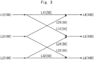
- Fig. 3 schematically illustrates the light intensities in the optical repeater 100 according to the first example embodiment.
- the light intensity of each of the lights L1 to L3 is "100" and the demultiplexer D1 branches the lights L1 at the same rate
- the light intensity of each of the branched light L11 and L12 is "50”.
- the light intensity of each of the branched light L21, L22, L31, and L32 is "50".
- the light intensity of each of the excitation lights L4 to L6 generated by multiplexing the two branched light is "100".
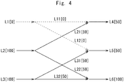
- FIG. 4 illustrates an example in which the light source S1 in the optical repeater 100 according to the first example embodiment fails. Since only the branched light L21 is output to the optical amplification unit A1 as the excitation light L4 when the light source S1 fails and the output of the light L1 stops, the light intensity of the excitation light L4 is "50". Further, since only the branched light L31 is output to the optical amplification unit A2 as the excitation light L5, the light intensity of the excitation light L5 is "50". The light intensity of the excitation light L6 is kept at "100".
- the optical repeater 100 since the optical repeater 100 has a redundant configuration that receives the lights from the two different light sources as the excitation light, even when one light source fails, the output of the excitation light to the optical amplification unit is not interrupted while the light intensity of the excitation light is reduced. Therefore, according to the present configuration, it is possible to provide the optical repeater capable of continuing to relay the optical signal even when the light source fails can be provided.
- the optical repeater may include two, four, or more light sources, and two, four, or more optical amplifiers.
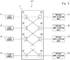
- Fig. 5 illustrates an optical repeater 101 including n light sources and n optical amplifiers, where n is an integer equal to or more than four.
- the optical repeater 101 includes the light sources S1 to Sn, an optical distribution unit 11, and the optical amplification units A1 to An.
- the optical distribution unit 11 includes the demultiplexers D1 to Dn and the multiplexers M1 to Mn. As the optical distribution unit 10, the optical distribution unit 11 branches the light output from each of the light sources S1 to Sn into two branched light, and distributes the branched lights in such a manner that each of the optical amplification units A1 to An receives two branched light output from the different light sources.
- the optical repeater 100 since the optical repeater 101 has the redundant configuration in which the optical amplification unit receives the lights from two different light sources as the excitation light, the relay of the optical signal can be continued even if the light source fails.
- the total number of the demultiplexers and the multiplexers through which the light output from the light source passes is kept at two and thereby does not increase, even when the number of the optical amplification units increases.
- complicated optical wiring is not required. Therefore, the number of the light sources and the number of the optical amplifiers can be selected without considering the complexity of the optical wiring, and thereby flexible design can be performed as appropriate. Further, loss of the light due to the demultiplexers and the multiplexers can be suppressed by suppressing the total number of those. As a result, as compared to Patent Literature 1, it is possible to more effectively use the light output from the light source as the excitation light.
- the failure affects only a part of the optical amplification units. Therefore, it is possible to reduce the influence of the failure of the light source on the relay of the optical signal.
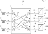
- Fig. 6 illustrates a modified example of the arrangement of the optical fibers in the optical distribution unit.
- the optical fiber F11 connects the output port of the demultiplexer D1 with the input port of the multiplexer M3.
- the optical fiber F32 connects the output port of the demultiplexer D3 with the input port of the multiplexer M1.
- the excitation light L4 is the light including the branched light L21 and the branched light L32
- the excitation light L6 is the light including the branched light L11 and the branched light L22.
- the optical repeater it is also possible to perform a design in which the wiring of the optical fiber is flexibly changed as appropriate.
- FIG. 7 schematically illustrates a configuration of an optical repeater 200 according to the second example embodiment.
- the optical repeater 200 includes light sources SD1 to SD3, an optical distribution unit 20, and optical amplification units AD1 to AD3.
- the light sources SD1 to SD3 correspond to the light sources S1 to S3 of the optical repeater 100, respectively.
- the optical amplification units AD1 to AD3 correspond to optical amplification units A1 to A3 of the optical repeater 100, respectively.
- the optical distribution unit 20 includes couplers C1 to C6.
- the couplers C1 to C3 correspond to the demultiplexers D1 to D3 of the optical distribution unit 10, respectively.
- the couplers C4 to C6 correspond to the multiplexers M1 to M3 of the optical distribution unit 10, respectively.
- Each of the couplers C1 to C6 has two input ports and two output ports. Each light input to a first or second input port is branched into two branched lights. One branched light generated by being input to the first input port and branched and one branched light generated by being input to the second input port and branched are multiplexed and output from a first output port. The other branched light generated by being input to the first input port and branched and the other branched light generated by being input to the second input port and branched are multiplexed and output from a second output port.
- Each of the light sources SD1 to SD3 has two light emitting elements. Specifically, the light sources SD1 has light emitting elements LD11 and LD12. The light sources SD2 has light emitting elements LD21 and LD22. The light sources SD3 has light emitting elements LD31 and LD32. For example, an element such as a semiconductor laser can be used as each light emitting element.
- the light emitting element LD11 outputs a light LA1 to one input port of the coupler C1 through an optical fiber FA1.
- the light emitting element LD12 outputs a light LB1 to the other input port of the coupler C1 through an optical fiber FB1.
- the coupler C1 branches the light LA1 into branched lights LA11 and LA12, and branches the light LB1 into branched lights LB11 and LB12.
- the coupler C1 multiplexes the branched lights LA11 and LB11, and multiplexes the branched lights LA12 and LB12.
- the multiplexed lights LA11 and LB11 are output from one output port of the coupler C1 to one input port of the coupler C4.
- the multiplexed lights LA12 and LB12 are output from the other output port of the coupler C1 to one input port of the coupler C5.
- the light emitting element LD21 outputs a light LA2 to one input port of the coupler C2 through an optical fiber FA2.
- the light emitting element LD22 outputs a light LB2 to the other input port of the coupler C2 through an optical fiber FB2.
- the coupler C2 branches the light LA2 into branched lights LA21 and LA22, and branches the light LB2 into branched lights LB21 and LB22.
- the coupler C2 multiplexes the branched lights LA21 and LB21, and multiplexes the branched lights LA22 and LB22.
- the multiplexed lights LA21 and LB21 are output from one output port of the coupler C2 to the other input port of the coupler C4.
- the multiplexed lights LA22 and LB22 are output from the other output port of the coupler C2 to one input port of the coupler C6.
- the light emitting element LD31 outputs a light LA3 to one input port of the coupler C3 through an optical fiber FA3.
- the light emitting element LD32 outputs a light LB3 to the other input port of the coupler C3 through an optical fiber FB3.
- the coupler C3 branches the light LA3 into branched lights LA31 and LA32, and branches the light LB3 into branched lights LB31 and LB32.
- the coupler C3 multiplexes the branched lights LA31 and LB31, and multiplexes the branched lights LA32 and LB32.
- the multiplexed lights LA31 and LB31 are output from one output port of the coupler C3 to the other input port of the coupler C5.
- the multiplexed lights LA32 and LB32 are output from the other output port of the coupler C3 to the other input port of the coupler C6.
- the couplers C4 to C6 branches the input light and multiplexes the branched lights as described above.
- an excitation light LA4 generated by multiplexing the branched lights LA11, LB11, LA21, and LB21 is output from one output port of the coupler C4.
- An excitation light LB4 generated by multiplexing the branched lights LA11, LB11, LA21, and LB21 is output from the other output port of the coupler C4.
- An excitation light LA5 generated by multiplexing the branched lights LA12, LB12, LA31, and LB31 is output from one output port of the coupler C5.
- An excitation light LB5 generated by multiplexing the branched lights LA12, LB12, LA31, and LB31 is output from the other output port of the coupler C5.
- An excitation light LA6 generated by multiplexing the branched lights LA22, LB22, LA32, and LB32 is output from one output port of the coupler C6.
- An excitation light LB6 generated by multiplexing the branched lights LA22, LB22, LA32, and LB32 is output from the other output port of the coupler C6.
- Each of the optical amplification units AD1 to AD3 includes two optical amplifiers.
- the optical amplification unit AD1 includes two optical amplifiers A11 and A12 that include the EDFs.
- the optical amplification unit AD2 includes two optical amplifiers A21 and A22 that includes the EDFs.
- the optical amplification unit AD3 includes two optical amplifiers A31 and A32 that includes the EDFs.
- the excitation light LA4 is input to the optical amplifier A11 of the optical amplification unit AD1 and the excitation light LB4 is input to the optical amplifier A12 of the optical amplification unit AD1.
- the excitation light LA5 is input to the optical amplifier A21 of the optical amplification unit AD2 and the excitation light LB5 is input to the optical amplifier A22 of the optical amplification unit AD2.
- the excitation light LA6 is input to the optical amplifier A31 of the optical amplification unit AD3 and the excitation light LB6 is input to the optical amplifier A32 of the optical amplification unit AD3.
- the light output from each light emitting element can be branched and the branched lights can be output to the different couplers, respectively.
- the light output from one light source is branched and the branched lights are output to the different optical amplification units, respectively, as in the first example embodiment.
- the optical repeater amplifies the optical signals transmitted through a fiber pair configured by an upstream optical fiber and a downstream optical fiber.
- the fiber pair may correspond to not only the communication direction but also a pair of frequently used bands (e.g. C-band and L-band) or the like.
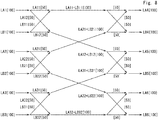
- Fig. 8 schematically illustrates light intensities in the optical repeater 200 according to the second example embodiment.
- the light intensities of the light LA1 to LA3 and LB1 to LB3 are "100”
- the light intensities of the branched lights branched by the couplers C1 to C3 are "50”.
- the light intensities of the lights output from the output ports of the couplers C1 to C3 are "100".
- the light intensities of the lights branched by the couplers C4 to C6 are "50", respectively.
- the light intensities of the excitation lights LA4 to LA6 and LB4 to LB6 output from the output ports of the couplers C4 to C6 are "100", respectively. Therefore, the light intensities of the excitation lights LA4 to LA6 and LB4 to LB6 are the same as each other.
- FIG. 9 illustrates an example in which the light emitting element LD12 of the light source SD1 in the optical repeater 200 according to the second example embodiment fails.
- the light intensity of the light LB1 is "0".
- the branched light LA11 whose light intensity is "50” is output from the coupler C1 to the coupler C4 and only the branched light LA12 whose light intensity is "50” is output from the coupler C1 to the coupler C5.
- the coupler C4 branches the branched light LA11 into two lights whose light intensities are "25".
- the coupler C5 branches the branched light LA12 into two lights whose light intensities are "25”.
- the light intensities of the excitation lights LA4, LB4, LA5, and LB5 are "75".
- the present configuration even when the other of the two light emitting elements included in one light source also fails, it is possible to continue to output the excitation light to the optical amplification unit while the light intensity of the excitation light is reduced to 1/2. Further, according to the present configuration, even when one of the two light emitting elements included in another light source further fails, it is possible to continue to output the excitation light to the optical amplification unit while the light intensity of the excitation light may be reduced to 1/2. Furthermore, even when three light emitting elements in four light emitting elements included in two light sources fail, it is possible to continue to output the excitation light to the optical amplification unit while the light intensity of the excitation light may be reduced to 1/4.
- the number of the light emitting elements disposed in the light source is not limited to two, and the number thereof may be three or more.
- the number of the input ports of the corresponding coupler may be appropriately changed according to the number of the light emitting elements
- an optical repeater according to a third example embodiment will be described.
- the demultiplexers D1 to D3 and the couplers C1 to C6 branch the input lights at the same rate and the excitation lights have the same light intensity.
- the light intensities of the excitation lights used by the optical amplification units are different depending on the use application.
- an optical repeater capable of corresponding to the case in which the light intensities of the excitation lights used by the optical amplification units are different.
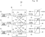
- Fig. 10 schematically illustrates a configuration of an optical repeater 300 according to the third example embodiment.
- the optical repeater 300 has a configuration in which the optical distribution unit 10 in the optical repeater 100 according to the first example embodiment is replaced with an optical distribution unit 30.
- a required light intensity of the excitation light L4 input to the optical amplification unit A1 is "120". It is also assumed that a required light intensity of the excitation light L5 input to the optical amplification unit A2 is "80”. Further, it is assumed that a required light intensity of the excitation light L6 input to the optical amplification unit A3 is "100".
- the optical distribution unit 30 has the configuration as the optical distribution unit 10 except that the light branching rates at the demultiplexers D1 to D3 are different from those in the optical distribution unit 10.
- the demultiplexer D1 branches the light L1 at different rates.
- the demultiplexer D1 branches the light L1 whose light intensity is "100" into the branched light L11 whose light intensity is "60” and the branched light L12 whose light intensity is "40".
- the demultiplexer D2 branches the light L2 at different rates.
- the demultiplexer D2 branches the light L2 whose light intensity is "100" into the branched light L21 whose light intensity is "60” and the branched light L22 whose light intensity is "40".
- the demultiplexer D3 branches the light L3 at different rates.
- the demultiplexer D6 branches the light L3 whose light intensity is "100" into the branched light L31 whose light intensity is "40” and the branched light L32 whose light intensity is "60".
- the light intensity of the excitation light L4 is "120"
- the light intensity of the excitation light L5 is “80”
- the light intensity of the excitation light L6 is "100”. Therefore, according to the optical repeater 300 illustrated in Fig. 10 , it is possible to easily cause the light intensity of the excitation light to be a desired value without increasing the number of components in the optical distribution unit only by changing the light branching rates at the demultiplexer.
- Fig. 11 schematically illustrates a configuration of an optical repeater 301 according to the third example embodiment.
- the configuration of the optical repeater 301 is the same as that of the optical repeater 100 except that the light intensities of the lights output from the light sources S1 to S3 are different.
- the required light intensities of the excitation lights L4 to L6 are "120", “90", and "90", respectively.
- the light intensity of the light L1 is “120”
- the light intensity of the light L2 is “120”
- the light intensity of the light L3 is "60”.
- the light intensities of the branched lights L11, L12, L21, and L22 are "60".
- the light intensities of the branched lights L31 and L32 are "30".
- the light intensity of the excitation light L4 is "120"
- the light intensity of the excitation light L5 is “90”
- the light intensity of the excitation light L6 is "90”. Therefore, according to the optical repeater 301 illustrated in Fig. 11 , it is possible to easily cause the light intensity of the excitation light to be a desired value without increasing the number of components only by changing the light intensity of the light output from the light source .
- the bands of the optical signals to be amplified are different, it may be necessary to set the light intensities of the excitation lights according to the bands.
- a C-band optical signal (1530nm to 1565nm) and an L-band optical signal (1565nm to 1625nm) are amplified will be described.
- the optical amplification unit amplifying the L-band optical signal requires a higher intensity excitation light than the optical amplification unit amplifying the C-band optical signal.
- it is possible to correspond to amplification of optical signals in different bands by setting the intensities of the excitation lights provided to the optical amplification units.
- the amplification of the C-band and L-band is merely an example. In sum, it should be appreciated that it is possible to appropriately correspond to amplification of the optical signals in two or more different bands including the C-band and L-band.
- the change of the light branching rates at the demultiplexer and the change of the light intensity of the light output from the light source may be combined to set the light intensity of the excitation light.
- the coupler has been used as the demultiplexer and multiplexer in the second example embodiment, it should be appreciated that the light branching rates at the coupler may be changed according to the required light intensity of the excitation light.
- FIG. 12 schematically illustrates a configuration of an optical repeater 400 according to the fourth example embodiment.
- modules having pillar shapes are arranged in a longitudinal direction of the case 40 (Z-direction in Fig. 12 ).
- a part of the case 40 is removed to illustrate the modules in the case 40.
- modules 41 to 44 are arranged in the case 40.
- Light sources, optical distribution units, and optical amplification units used for relaying the optical signal are installed in the modules 41 to 44.
- the light sources S1 and S2, the demultiplexers D1 and D2, and the optical amplification units A1 and A2 illustrated in Fig. 2 are installed in the module 42.
- the optical fibers F1, F2, F4, F5, F11, F12, and F21 are housed in the module 42.
- the light source S3, the demultiplexer D3, and the optical amplification unit A3 illustrated in Fig. 2 are installed in the module 43.
- the optical fibers F3, F6, and F32 are housed in the module 43.
- the optical fiber F22 is laid between the module 42 and the module 43 to connect the demultiplexer D2 in the module 42 with the multiplexer M3 in the module 43.
- the optical fiber F31 is laid between the module 42 and the module 43 to connect the demultiplexer D3 in the module 43 with the multiplexer M2 in the module 42.
- a groove 50 for guiding the optical fiber is formed on side surfaces of the modules 42 and 42.
- the optical fibers F22 and F31 are housed in the groove 50.
- the optical repeater 100 illustrated in Fig. 2 can be configured by connecting the modulus with the optical fibers. Note that it should be appreciated that the same applies to the case in which the components constituting the optical repeater according to the second and third example embodiments are dispersedly installed in the different modules.
- the shape of the case described above is merely an example and it may be another shape other than the cylindrical shape.
- the modules are arranged in the longitudinal direction of the case, the arrangement of the modules is not limited to this.
- the present disclosure is not limited to the example embodiments mentioned above and can be modified as appropriate without departing from the gist of the present disclosure.
- the optical components disposed in the optical repeater are connected by the optical fibers, it is merely an example.
- a part or all of the optical fibers connecting the optical components disposed in the optical repeater may be an optical waveguide other that the optical fiber.
- the light source includes two light emitting elements in the second example embodiment, it may include three or more light emitting elements.
- the coupler connected with one light source may branch the light output from each of two or more light emitting elements at the same rate or the different rates.
- the light intensities of the lights output from the two or more light emitting elements may be the same or different according to the required light intensities of the excitation lights.
- the light amplification unit includes two optical amplifiers in the second example embodiment, it may include three or more optical amplifiers.
- the coupler connected with one optical amplification unit may branch the multiplexed light at the same rate or the different rates and respectively output the branched lights to tow or more optical amplifiers.
- a manufacturing method of the optical repeater according to the example embodiments described above can be achieved by disposing the light source and the optical amplification unit descried in the above-described example embodiments and disposing the optical distribution unit descried in the above-described example embodiments. Further, it should be appreciated that a relay method of the optical signal can be achieved by applying the optical repeater and amplifying the optical signal.
- the light intensity of the light output from the light source that does not fail may be increased within an allowable range so as to maintain the light intensity of the excitation light.
- a control unit may be disposed in the optical repeater, and the control unit may detect the failure of the light source and control the light source that does not fail.
- the light intensities of the excitation lights L1 to L3 can be kept within a desired range.
- Fig. 13 illustrates an alternative example of the optical repeater according to example embodiments described above.
- the optical repeater illustrated in Fig. 13 had a configuration in which a control unit 60 is added to the optical repeater 100 according to the first example embodiment.
- the control unit 60 can receive a failure detection signal DET and detect the failure of the light source.
- the control unit 60 can control the light intensities of the lights output from the light sources that do not fail in the light sources S1 to S3 by using control signals CON1 to CON3 in response to the failure detection result, respectively.
- the failure detection signal DET may be provided from a determination unit that determines an occurrence of the failure of the light source to the control unit 60. This determination unit may be disposed in the optical repeater or the outside thereof.
- the light source may detect the failure and output the failure detection signal DET to the control unit 60.
- optical amplifier and the optical amplification unit including the EDF have been described above, the optical amplifier and the optical amplification unit may include a rare-earth doped fiber other than the EDF.
Landscapes
- Physics & Mathematics (AREA)
- Electromagnetism (AREA)
- Engineering & Computer Science (AREA)
- Plasma & Fusion (AREA)
- Optics & Photonics (AREA)
- Computer Networks & Wireless Communication (AREA)
- Signal Processing (AREA)
- Microelectronics & Electronic Packaging (AREA)
- Lasers (AREA)
- Optical Communication System (AREA)
Abstract
Description
- The present invention relates to an optical repeater, a manufacturing method of an optical repeater, and a relay method of an optical signal.
- In an optical communication system such as a submarine optical cable system, at least one optical repeater is inserted in a transmission path so as to compensate attenuation of an optical signal. The optical repeater includes an optical amplifier that amplifies the optical signal. As such an optical amplifier, an Erbium-doped fiber amplifier (EDFA) capable of directly amplifying the optical signal is used.
- A fiber-type optical amplification apparatus including the EDFA has been proposed (Patent Literature 1). In the fiber-type optical amplification apparatus, eight excitation light sources are disposed for eight Erbium-doped fiber (EDF) units. An excitation light output from each excitation light source is equally branched into eight lights by a fiber coupler and the branched eight lights are distributed to the eight EDF units. In this configuration, the light output from one excitation light source is distributed to the eight EDF units by passing through two-input/two-output distributor three times. That is, the fiber-type optical amplification apparatus employs a redundant configuration in which each EDF unit receives the excitation light output from each excitation light source by 1/8.
- Thus, even when the excitation light source fails and the output of the excitation light is stopped, it is possible to suppress a decrease in a level of the excitation light received by the EDF unit and control the output of the excitation light source that does not fail so as to restore the level of the excitation light received by the EDF unit.
- Patent Literature 1: Japanese Unexamined Patent Application Publication NO.
H4-234738 - However, the fiber-type optical amplification apparatus described above has the following problems. In the fiber-type optical amplification apparatus, since the excitation light output from the excitation light source is equally branched by the number of the EDF units, many distributors are disposed in the fiber coupler and it is necessary to connect between the distributors by optical wiring. Therefore, a complicated wiring configuration to connect between the distributors is required and wiring work is also complicated. Especially, since the number of the distributors through which the light output from the excitation light source passes increases as the number of the EDF units increase, the wiring configuration becomes more complicated. The fiber-type optical amplification apparatus also has a prominent disadvantage that the failure of one excitation light source affects all EDF units.
- The present disclosure has been made in view of the matters mentioned above and has an object to provide an optical repeater, a manufacturing method of an optical repeater, and a relay method of an optical signal that can achieve a redundant configuration for a failure of a light source outputting an excitation light with a simple configuration.
- An aspect of the present invention is an optical repeater including: three or more light sources configured to output lights; three or more optical amplification units configured to amplify optical signals using input excitation lights; and an optical distribution unit configured to branch the light output from each of the three or more light sources into two branched lights and distribute the branched lights in such a manner that each of the three or more optical amplification units receives the branched lights branched from the lights from two different light sources as the excitation light.
- An aspect of the present invention is a manufacturing method of an optical repeater including: disposing three or more light sources configured to output lights; disposing three or more optical amplification units configured to amplify optical signals using input excitation lights, and disposing an optical distribution unit between the three or more light sources and the three or more optical amplification units, the optical distribution unit being configured to branch the light output from each of the three or more light sources into two branched lights and distribute the branched lights in such a manner that each of the three or more optical amplification units receives the branched lights branched from the lights from two different light sources as the excitation light.
- An aspect of the present invention is a relay method of an optical signal including: branching a light output from each of three or more light sources into two branched lights, and distributing the branched lights to three or more optical amplification units in such a manner that each of the three or more optical amplification units that amplifies an optical signal using input excitation lights receives the branched lights branched from the lights from two different light sources as the excitation light.
- According to the present disclosure, it is possible to provide an optical repeater, a manufacturing method of an optical repeater, and a relay method of an optical signal that can achieve a redundant configuration for a failure of a light source outputting an excitation light with a simple configuration.
-
-
Fig. 1 schematically illustrates a configuration of an optical repeater according to a first example embodiment; -
Fig. 2 illustrates the configuration of the optical repeater according to the first example embodiment in more detail; -
Fig. 3 schematically illustrates light intensities in the optical repeater according to the first example embodiment; -
Fig. 4 illustrates an example in which a light source in the optical repeater according to the first example embodiment fails; -
Fig. 5 illustrates an optical repeater including n light sources and n optical amplifiers, where n is an integer equal to or more than four; -
Fig. 6 illustrates a modified example of an arrangement of optical fibers in an optical distribution unit; -
Fig. 7 schematically illustrates a configuration of an optical repeater according to a second example embodiment; -
Fig. 8 schematically illustrates light intensities in the optical repeater according to the second example embodiment; -
Fig. 9 illustrates an example in which a light emitting element of a light source in the optical repeater according to the second example embodiment fails; -
Fig. 10 schematically illustrates a configuration of an optical repeater according to a third example embodiment; -
Fig. 11 schematically illustrates a configuration of an optical repeater according to the third example embodiment; -
Fig. 12 schematically illustrates a configuration of an optical repeater according to a fourth example embodiment; and -
Fig. 13 illustrates an alternative example of the optical repeater. - Hereinbelow, example embodiments of the present disclosure are explained with reference to the drawings. The same symbols are assigned to the same elements throughout the drawings and duplicated explanations are omitted as necessary.
- An optical repeater according to a first example embodiment will be described.
Fig. 1 schematically illustrates a configuration of anoptical repeater 100 according to the first example embodiment. Theoptical repeater 100 includes light sources S1 to S3, anoptical distribution unit 10, and optical amplification units A1 to A3. - The light sources S1 to S3 output lights L1 to L3 through optical fibers F1 to F3 to the
optical distribution unit 10, respectively. - The
optical distribution unit 10 is configured as an optical distribution circuit that distributes the lights L1 to L3 to the optical amplification units A1 to A3. Theoptical distribution unit 10 branches each of the lights L1 to L3 into two branched lights. Specifically, the light L1 is branched into a branched light L11 and a branched light L12. The light L2 is branched into a branched light L21 and a branched light L22. The light L3 is branched into a branched light L31 and a branched light L32. - The
optical distribution unit 10 distributes the branched lights L11, L12, L21, L22, L31, and L32 in such a manner that each of the optical amplification units A1 to A3 receives two branched lights output from the different light sources. Specifically, theoptical distribution unit 10 outputs an excitation light L4 generated by multiplexing the branched light L11 and the branched light L21 to the optical amplification unit A1 through an optical fiber F4. Theoptical distribution unit 10 outputs an excitation light L5 generated by multiplexing the branched light L12 and the branched light L31 to the optical amplification unit A2 through an optical fiber F5. Theoptical distribution unit 10 outputs an excitation light L6 generated by multiplexing the branched light L22 and the branched light L32 to the optical amplification unit A3 through an optical fiber F6. - The optical amplification units A1 to A3 are configured as optical amplifiers directly amplifying optical signals SIG1 to SIG3 using the excitation lights L4 to L6, respectively.
The optical amplification units A1 to A3 are configured to include Erbium-doped fiber amplifiers (EDFAs) in which Erbium-doped fibers (EDFs) 1 to 3 are disposed, respectively. When the excitation lights L4 to L6 are input to theEDFs 1 to 3 of the optical amplification units A1 to A3, theEDFs 1 to 3 are excited, respectively. Then, when the optical signals SIG1 to SIG3 are input to theexcited EDFs 1 to 3, the optical signals SIG1 to SIG3 are amplified, respectively. - The
optical distribution unit 10 will be described below.Fig. 2 illustrates the configuration of theoptical repeater 100 according to the first example embodiment in more detail.
Theoptical distribution unit 10 includes demultiplexers D1 to D3 and multiplexers M1 to M3. - The demultiplexers D1 to D3 are configured as a Y-branch that branches an input light into two lights. The multiplexers M1 to M3 are configured as a Y-branch that multiplexes two input lights.
- The fiber F1 connects between the light source S1 and an input port of the demultiplexer D1. The fiber F2 connects between the light source S2 and an input port of the demultiplexer D2. The fiber F3 connects between the light source S3 and an input port of the demultiplexer D3.
- One output port of the demultiplexer D1 and one input port of the multiplexer M1 are connected by an optical fiber F11. The other output port of the demultiplexer D1 and one input port of the multiplexer M2 are connected by an optical fiber F12. One output port of the demultiplexer D2 and the other input port of the multiplexer M1 are connected by an optical fiber F21. The other output port of the demultiplexer D2 and one input port of the multiplexer M3 are connected by an optical fiber F22. One output port of the demultiplexer D3 and the other input port of the multiplexer M2 are connected by an optical fiber F31. The other output port of the demultiplexer D3 and the other input port of the multiplexer M3 are connected by an optical fiber F32.
- An output port of the multiplexer M1 and an input port of the optical amplification unit A1 are connected by the optical fiber F4. An output port of the multiplexer M2 and an input port of the optical amplification unit A2 are connected by the optical fiber F5. An output port of the multiplexer M3 and an input port of the optical amplification unit A3 are connected by the optical fiber F6.
- Next, transmission paths of the light in the
optical distribution unit 10 will be described. The demultiplexer D1 branches the light L1 into the branched light L11 and the branched light L12. The branched light L11 is output to the multiplexer M1 through the optical fiber F11. The branched light L12 is output to the multiplexer M2 through the optical fiber F12. The demultiplexer D2 branches the light L2 into the branched light L21 and the branched light L22. The branched light L21 is output to the multiplexer M1 through the optical fiber F21. The branched light L22 is output to the multiplexer M3 through the optical fiber F22. The demultiplexer D3 branches the light L3 into the branched light L31 and the branched light L32. The branched light L31 is output to the multiplexer M2 through the optical fiber F31. The branched light L32 is output to the multiplexer M3 through the optical fiber F32. - The multiplexer M1 multiplexes the branched light L11 and the branched light L21 so as to output the excitation light L4 to the optical amplification unit A1 through the optical fiber F4. The multiplexer M2 multiplexes the branched light L12 and the branched light L31 so as to output the excitation light L5 to the optical amplification unit A2 through the optical fiber F5. The multiplexer M3 multiplexes the branched light L22 and the branched light L32 so as to output the excitation light L6 to the optical amplification unit A3 through the optical fiber F6.
- When the lights L1 to L3 have the same light intensity, and the demultiplexers D1 to D3 branch the lights L1 to L3 at the same rate, respectively, the excitation lights L4 to L6 have the same light intensity.
Fig. 3 schematically illustrates the light intensities in theoptical repeater 100 according to the first example embodiment. When the light intensity of each of the lights L1 to L3 is "100" and the demultiplexer D1 branches the lights L1 at the same rate, the light intensity of each of the branched light L11 and L12 is "50". Similarly, the light intensity of each of the branched light L21, L22, L31, and L32 is "50". Thus, the light intensity of each of the excitation lights L4 to L6 generated by multiplexing the two branched light is "100". - Next, the case in which the light source in the
optical repeater 100 fails will be considered.Fig. 4 illustrates an example in which the light source S1 in theoptical repeater 100 according to the first example embodiment fails. Since only the branched light L21 is output to the optical amplification unit A1 as the excitation light L4 when the light source S1 fails and the output of the light L1 stops, the light intensity of the excitation light L4 is "50". Further, since only the branched light L31 is output to the optical amplification unit A2 as the excitation light L5, the light intensity of the excitation light L5 is "50". The light intensity of the excitation light L6 is kept at "100". - Thus, since the
optical repeater 100 has a redundant configuration that receives the lights from the two different light sources as the excitation light, even when one light source fails, the output of the excitation light to the optical amplification unit is not interrupted while the light intensity of the excitation light is reduced. Therefore, according to the present configuration, it is possible to provide the optical repeater capable of continuing to relay the optical signal even when the light source fails can be provided. - In the above description, although an example in which the optical repeater includes three light sources and three optical amplifiers has been described, the number of the light sources and the number of the optical amplifiers are not limited to three. In sum, the optical repeater may include two, four, or more light sources, and two, four, or more optical amplifiers.
Fig. 5 illustrates anoptical repeater 101 including n light sources and n optical amplifiers, where n is an integer equal to or more than four. - The
optical repeater 101 includes the light sources S1 to Sn, anoptical distribution unit 11, and the optical amplification units A1 to An. Theoptical distribution unit 11 includes the demultiplexers D1 to Dn and the multiplexers M1 to Mn. As theoptical distribution unit 10, theoptical distribution unit 11 branches the light output from each of the light sources S1 to Sn into two branched light, and distributes the branched lights in such a manner that each of the optical amplification units A1 to An receives two branched light output from the different light sources. - Accordingly, as the
optical repeater 100, since theoptical repeater 101 has the redundant configuration in which the optical amplification unit receives the lights from two different light sources as the excitation light, the relay of the optical signal can be continued even if the light source fails. - In the present configuration, unlike
Patent Literature 1, the total number of the demultiplexers and the multiplexers through which the light output from the light source passes is kept at two and thereby does not increase, even when the number of the optical amplification units increases. Thus, complicated optical wiring is not required. Therefore, the number of the light sources and the number of the optical amplifiers can be selected without considering the complexity of the optical wiring, and thereby flexible design can be performed as appropriate. Further, loss of the light due to the demultiplexers and the multiplexers can be suppressed by suppressing the total number of those. As a result, as compared toPatent Literature 1, it is possible to more effectively use the light output from the light source as the excitation light. - In the optical repeater according to the present example embodiment, even when one light source fails, the failure affects only a part of the optical amplification units. Therefore, it is possible to reduce the influence of the failure of the light source on the relay of the optical signal.
- Note that the arrangement of the optical fibers in the
optical distribution unit 10 illustrated inFig. 2 is merely an example. As long as each of the optical amplification units A1 to A3 can receive the excitation light generated by multiplexing the lights output from the two different light sources, the arrangement of the optical fibers in the optical distribution unit may be changed as appropriate.Fig. 6 illustrates a modified example of the arrangement of the optical fibers in the optical distribution unit. - In an
optical distribution unit 12 in anoptical repeater 102 illustrated inFig. 6 , the optical fiber F11 connects the output port of the demultiplexer D1 with the input port of the multiplexer M3. The optical fiber F32 connects the output port of the demultiplexer D3 with the input port of the multiplexer M1. As a result, the excitation light L4 is the light including the branched light L21 and the branched light L32, and the excitation light L6 is the light including the branched light L11 and the branched light L22. - As described above, according to the use of the optical repeater, it is also possible to perform a design in which the wiring of the optical fiber is flexibly changed as appropriate.
- An optical repeater according to a second example embodiment will be described.
Fig. 7 schematically illustrates a configuration of anoptical repeater 200 according to the second example embodiment. Theoptical repeater 200 includes light sources SD1 to SD3, anoptical distribution unit 20, and optical amplification units AD1 to AD3. The light sources SD1 to SD3 correspond to the light sources S1 to S3 of theoptical repeater 100, respectively. The optical amplification units AD1 to AD3 correspond to optical amplification units A1 to A3 of theoptical repeater 100, respectively. - The
optical distribution unit 20 includes couplers C1 to C6. The couplers C1 to C3 correspond to the demultiplexers D1 to D3 of theoptical distribution unit 10, respectively. The couplers C4 to C6 correspond to the multiplexers M1 to M3 of theoptical distribution unit 10, respectively. - Each of the couplers C1 to C6 has two input ports and two output ports. Each light input to a first or second input port is branched into two branched lights. One branched light generated by being input to the first input port and branched and one branched light generated by being input to the second input port and branched are multiplexed and output from a first output port. The other branched light generated by being input to the first input port and branched and the other branched light generated by being input to the second input port and branched are multiplexed and output from a second output port.
- Each of the light sources SD1 to SD3 has two light emitting elements. Specifically, the light sources SD1 has light emitting elements LD11 and LD12. The light sources SD2 has light emitting elements LD21 and LD22. The light sources SD3 has light emitting elements LD31 and LD32. For example, an element such as a semiconductor laser can be used as each light emitting element.
- The light emitting element LD11 outputs a light LA1 to one input port of the coupler C1 through an optical fiber FA1. The light emitting element LD12 outputs a light LB1 to the other input port of the coupler C1 through an optical fiber FB1. The coupler C1 branches the light LA1 into branched lights LA11 and LA12, and branches the light LB1 into branched lights LB11 and LB12. The coupler C1 multiplexes the branched lights LA11 and LB11, and multiplexes the branched lights LA12 and LB12. The multiplexed lights LA11 and LB11 are output from one output port of the coupler C1 to one input port of the coupler C4. The multiplexed lights LA12 and LB12 are output from the other output port of the coupler C1 to one input port of the coupler C5.
- The light emitting element LD21 outputs a light LA2 to one input port of the coupler C2 through an optical fiber FA2. The light emitting element LD22 outputs a light LB2 to the other input port of the coupler C2 through an optical fiber FB2. The coupler C2 branches the light LA2 into branched lights LA21 and LA22, and branches the light LB2 into branched lights LB21 and LB22. The coupler C2 multiplexes the branched lights LA21 and LB21, and multiplexes the branched lights LA22 and LB22. The multiplexed lights LA21 and LB21 are output from one output port of the coupler C2 to the other input port of the coupler C4. The multiplexed lights LA22 and LB22 are output from the other output port of the coupler C2 to one input port of the coupler C6.
- The light emitting element LD31 outputs a light LA3 to one input port of the coupler C3 through an optical fiber FA3. The light emitting element LD32 outputs a light LB3 to the other input port of the coupler C3 through an optical fiber FB3. The coupler C3 branches the light LA3 into branched lights LA31 and LA32, and branches the light LB3 into branched lights LB31 and LB32. The coupler C3 multiplexes the branched lights LA31 and LB31, and multiplexes the branched lights LA32 and LB32. The multiplexed lights LA31 and LB31 are output from one output port of the coupler C3 to the other input port of the coupler C5. The multiplexed lights LA32 and LB32 are output from the other output port of the coupler C3 to the other input port of the coupler C6.
- The couplers C4 to C6 branches the input light and multiplexes the branched lights as described above. As a result, an excitation light LA4 generated by multiplexing the branched lights LA11, LB11, LA21, and LB21 is output from one output port of the coupler C4. An excitation light LB4 generated by multiplexing the branched lights LA11, LB11, LA21, and LB21 is output from the other output port of the coupler C4.
- An excitation light LA5 generated by multiplexing the branched lights LA12, LB12, LA31, and LB31 is output from one output port of the coupler C5. An excitation light LB5 generated by multiplexing the branched lights LA12, LB12, LA31, and LB31 is output from the other output port of the coupler C5.
- An excitation light LA6 generated by multiplexing the branched lights LA22, LB22, LA32, and LB32 is output from one output port of the coupler C6. An excitation light LB6 generated by multiplexing the branched lights LA22, LB22, LA32, and LB32 is output from the other output port of the coupler C6.
- Each of the optical amplification units AD1 to AD3 includes two optical amplifiers. Specifically, the optical amplification unit AD1 includes two optical amplifiers A11 and A12 that include the EDFs. The optical amplification unit AD2 includes two optical amplifiers A21 and A22 that includes the EDFs. The optical amplification unit AD3 includes two optical amplifiers A31 and A32 that includes the EDFs.
- The excitation light LA4 is input to the optical amplifier A11 of the optical amplification unit AD1 and the excitation light LB4 is input to the optical amplifier A12 of the optical amplification unit AD1. The excitation light LA5 is input to the optical amplifier A21 of the optical amplification unit AD2 and the excitation light LB5 is input to the optical amplifier A22 of the optical amplification unit AD2. The excitation light LA6 is input to the optical amplifier A31 of the optical amplification unit AD3 and the excitation light LB6 is input to the optical amplifier A32 of the optical amplification unit AD3.
- As described above, in the present configuration, even when the light source includes two light emitting elements, the light output from each light emitting element can be branched and the branched lights can be output to the different couplers, respectively. As a result, it can be understood that the light output from one light source is branched and the branched lights are output to the different optical amplification units, respectively, as in the first example embodiment.
- In general, in the optical communication, an upstream optical signal and a downstream optical signal are often handled as a pair. Thus, the optical repeater amplifies the optical signals transmitted through a fiber pair configured by an upstream optical fiber and a downstream optical fiber. In this case, by applying one optical amplification unit according to the present example embodiment to one fiber pair, it is possible to easily correspond to an operation per one fiber pair. Note that the fiber pair may correspond to not only the communication direction but also a pair of frequently used bands (e.g. C-band and L-band) or the like.
- When the light intensities of the lights output from the light emitting elements are the same as each other and the couplers C1 to C6 branch the light at the same rate, the light intensities of the excitation lights output from the couplers C4 to C6 are the same as each other.
Fig. 8 schematically illustrates light intensities in theoptical repeater 200 according to the second example embodiment. When the light intensities of the light LA1 to LA3 and LB1 to LB3 are "100", the light intensities of the branched lights branched by the couplers C1 to C3 are "50". Thus, the light intensities of the lights output from the output ports of the couplers C1 to C3 are "100". - The light intensities of the lights branched by the couplers C4 to C6 are "50", respectively. Thus, the light intensities of the excitation lights LA4 to LA6 and LB4 to LB6 output from the output ports of the couplers C4 to C6 are "100", respectively. Therefore, the light intensities of the excitation lights LA4 to LA6 and LB4 to LB6 are the same as each other.
- Next, the case in which the light source in the
optical repeater 200 fails will be considered.Fig. 9 illustrates an example in which the light emitting element LD12 of the light source SD1 in theoptical repeater 200 according to the second example embodiment fails. When the light emitting element LD12 fails and the output of the light LB1 stops, the light intensity of the light LB1 is "0". Thus, only the branched light LA11 whose light intensity is "50" is output from the coupler C1 to the coupler C4 and only the branched light LA12 whose light intensity is "50" is output from the coupler C1 to the coupler C5. - The coupler C4 branches the branched light LA11 into two lights whose light intensities are "25". The coupler C5 branches the branched light LA12 into two lights whose light intensities are "25". As a result, the light intensities of the excitation lights LA4, LB4, LA5, and LB5 are "75".
- As described above, according to the present configuration, even when one of the two light emitting elements included in one light source fails, it is possible to continue to output the excitation light to the optical amplification unit while the light intensity of the excitation light is reduced to 3/4.
- Note that, according to the present configuration, even when the other of the two light emitting elements included in one light source also fails, it is possible to continue to output the excitation light to the optical amplification unit while the light intensity of the excitation light is reduced to 1/2. Further, according to the present configuration, even when one of the two light emitting elements included in another light source further fails, it is possible to continue to output the excitation light to the optical amplification unit while the light intensity of the excitation light may be reduced to 1/2. Furthermore, even when three light emitting elements in four light emitting elements included in two light sources fail, it is possible to continue to output the excitation light to the optical amplification unit while the light intensity of the excitation light may be reduced to 1/4.
- The number of the light emitting elements disposed in the light source is not limited to two, and the number thereof may be three or more. The number of the input ports of the corresponding coupler may be appropriately changed according to the number of the light emitting elements
- In sum, by disposing a plurality of the light emitting elements in the light source, even when the failure of the light source occurs, it is possible to further reduce the risk of the excitation light being cut off.
- An optical repeater according to a third example embodiment will be described. In the example embodiments described above, it has been described that the demultiplexers D1 to D3 and the couplers C1 to C6 branch the input lights at the same rate and the excitation lights have the same light intensity. However, it can be considered that the light intensities of the excitation lights used by the optical amplification units are different depending on the use application. In the present example embodiment, an optical repeater capable of corresponding to the case in which the light intensities of the excitation lights used by the optical amplification units are different.
-
Fig. 10 schematically illustrates a configuration of anoptical repeater 300 according to the third example embodiment. Theoptical repeater 300 has a configuration in which theoptical distribution unit 10 in theoptical repeater 100 according to the first example embodiment is replaced with anoptical distribution unit 30. In the present example embodiment, it is assumed that a required light intensity of the excitation light L4 input to the optical amplification unit A1 is "120". It is also assumed that a required light intensity of the excitation light L5 input to the optical amplification unit A2 is "80". Further, it is assumed that a required light intensity of the excitation light L6 input to the optical amplification unit A3 is "100". - The
optical distribution unit 30 has the configuration as theoptical distribution unit 10 except that the light branching rates at the demultiplexers D1 to D3 are different from those in theoptical distribution unit 10. - The demultiplexer D1 branches the light L1 at different rates. In this example, the demultiplexer D1 branches the light L1 whose light intensity is "100" into the branched light L11 whose light intensity is "60" and the branched light L12 whose light intensity is "40".
- The demultiplexer D2 branches the light L2 at different rates. In this example, the demultiplexer D2 branches the light L2 whose light intensity is "100" into the branched light L21 whose light intensity is "60" and the branched light L22 whose light intensity is "40".
- The demultiplexer D3 branches the light L3 at different rates. In this example, the demultiplexer D6 branches the light L3 whose light intensity is "100" into the branched light L31 whose light intensity is "40" and the branched light L32 whose light intensity is "60".
- Thus, the light intensity of the excitation light L4 is "120", the light intensity of the excitation light L5 is "80", and the light intensity of the excitation light L6 is "100". Therefore, according to the
optical repeater 300 illustrated inFig. 10 , it is possible to easily cause the light intensity of the excitation light to be a desired value without increasing the number of components in the optical distribution unit only by changing the light branching rates at the demultiplexer. - Further, the light intensity of the excitation light can be changed by changing the light intensity of the light output from the light source.
Fig. 11 schematically illustrates a configuration of anoptical repeater 301 according to the third example embodiment. The configuration of theoptical repeater 301 is the same as that of theoptical repeater 100 except that the light intensities of the lights output from the light sources S1 to S3 are different. Here, it is assumed that the required light intensities of the excitation lights L4 to L6 are "120", "90", and "90", respectively. - In the present example embodiment, the light intensity of the light L1 is "120", the light intensity of the light L2 is "120", and the light intensity of the light L3 is "60".
- Thus, the light intensities of the branched lights L11, L12, L21, and L22 are "60". The light intensities of the branched lights L31 and L32 are "30".
- As a result, the light intensity of the excitation light L4 is "120", the light intensity of the excitation light L5 is "90", and the light intensity of the excitation light L6 is "90". Therefore, according to the
optical repeater 301 illustrated inFig. 11 , it is possible to easily cause the light intensity of the excitation light to be a desired value without increasing the number of components only by changing the light intensity of the light output from the light source . - For example, when the bands of the optical signals to be amplified are different, it may be necessary to set the light intensities of the excitation lights according to the bands. An example in which a C-band optical signal (1530nm to 1565nm) and an L-band optical signal (1565nm to 1625nm) are amplified will be described. In general, the optical amplification unit amplifying the L-band optical signal requires a higher intensity excitation light than the optical amplification unit amplifying the C-band optical signal. In this case, as illustrated in
Figs. 10 and11 , it is possible to correspond to amplification of optical signals in different bands by setting the intensities of the excitation lights provided to the optical amplification units. Note that the amplification of the C-band and L-band is merely an example. In sum, it should be appreciated that it is possible to appropriately correspond to amplification of the optical signals in two or more different bands including the C-band and L-band. - It should be appreciated that the change of the light branching rates at the demultiplexer and the change of the light intensity of the light output from the light source may be combined to set the light intensity of the excitation light. Although the coupler has been used as the demultiplexer and multiplexer in the second example embodiment, it should be appreciated that the light branching rates at the coupler may be changed according to the required light intensity of the excitation light.
- An optical repeater according to a fourth example embodiment will be described. Here, an installation of the optical repeater according to the example embodiments described above will be described.
Fig. 12 schematically illustrates a configuration of anoptical repeater 400 according to the fourth example embodiment. In acase 40 having a cylindrical shape in theoptical repeater 400, modules having pillar shapes are arranged in a longitudinal direction of the case 40 (Z-direction inFig. 12 ). InFig. 12 , a part of thecase 40 is removed to illustrate the modules in thecase 40. In this example, as illustrated inFig. 12 ,modules 41 to 44 are arranged in thecase 40. - Light sources, optical distribution units, and optical amplification units used for relaying the optical signal are installed in the
modules 41 to 44. - In this example, the light sources S1 and S2, the demultiplexers D1 and D2, and the optical amplification units A1 and A2 illustrated in
Fig. 2 are installed in themodule 42. Thus, the optical fibers F1, F2, F4, F5, F11, F12, and F21 are housed in themodule 42. - The light source S3, the demultiplexer D3, and the optical amplification unit A3 illustrated in
Fig. 2 are installed in themodule 43. Thus, the optical fibers F3, F6, and F32 are housed in themodule 43. - In this case, the optical fiber F22 is laid between the
module 42 and themodule 43 to connect the demultiplexer D2 in themodule 42 with the multiplexer M3 in themodule 43. The optical fiber F31 is laid between themodule 42 and themodule 43 to connect the demultiplexer D3 in themodule 43 with the multiplexer M2 in themodule 42. For example, as illustrated inFig. 12 , agroove 50 for guiding the optical fiber is formed on side surfaces of themodules groove 50. - As described above, even when the components constituting the
optical repeater 100 illustrated inFig. 2 are dispersedly installed in the different optical modules, it can be understood that the optical repeater can be configured by connecting the modulus with the optical fibers. Note that it should be appreciated that the same applies to the case in which the components constituting the optical repeater according to the second and third example embodiments are dispersedly installed in the different modules. - The shape of the case described above is merely an example and it may be another shape other than the cylindrical shape. Although the modules are arranged in the longitudinal direction of the case, the arrangement of the modules is not limited to this.
- Note that the present disclosure is not limited to the example embodiments mentioned above and can be modified as appropriate without departing from the gist of the present disclosure. For example, in the example embodiments described above, although it has been described that the optical components disposed in the optical repeater are connected by the optical fibers, it is merely an example. A part or all of the optical fibers connecting the optical components disposed in the optical repeater may be an optical waveguide other that the optical fiber.
- Although the light source includes two light emitting elements in the second example embodiment, it may include three or more light emitting elements. In this case, the coupler connected with one light source may branch the light output from each of two or more light emitting elements at the same rate or the different rates. Further, the light intensities of the lights output from the two or more light emitting elements may be the same or different according to the required light intensities of the excitation lights.
- Although the light amplification unit includes two optical amplifiers in the second example embodiment, it may include three or more optical amplifiers. In this case, the coupler connected with one optical amplification unit may branch the multiplexed light at the same rate or the different rates and respectively output the branched lights to tow or more optical amplifiers.
- It should be appreciated that a manufacturing method of the optical repeater according to the example embodiments described above can be achieved by disposing the light source and the optical amplification unit descried in the above-described example embodiments and disposing the optical distribution unit descried in the above-described example embodiments. Further, it should be appreciated that a relay method of the optical signal can be achieved by applying the optical repeater and amplifying the optical signal.
- When the light source fails in the optical repeater according to the example embodiments described above, the light intensity of the light output from the light source that does not fail may be increased within an allowable range so as to maintain the light intensity of the excitation light. In this case, a control unit may be disposed in the optical repeater, and the control unit may detect the failure of the light source and control the light source that does not fail. Thus, the light intensities of the excitation lights L1 to L3 can be kept within a desired range.
-
Fig. 13 illustrates an alternative example of the optical repeater according to example embodiments described above. The optical repeater illustrated inFig. 13 had a configuration in which acontrol unit 60 is added to theoptical repeater 100 according to the first example embodiment. Thecontrol unit 60 can receive a failure detection signal DET and detect the failure of the light source. Thecontrol unit 60 can control the light intensities of the lights output from the light sources that do not fail in the light sources S1 to S3 by using control signals CON1 to CON3 in response to the failure detection result, respectively. The failure detection signal DET may be provided from a determination unit that determines an occurrence of the failure of the light source to thecontrol unit 60. This determination unit may be disposed in the optical repeater or the outside thereof. The light source may detect the failure and output the failure detection signal DET to thecontrol unit 60. - The optical amplifier and the optical amplification unit including the EDF have been described above, the optical amplifier and the optical amplification unit may include a rare-earth doped fiber other than the EDF.
- The present disclosure has been described above with reference to the example embodiments, however, the present disclosure is not to be limited to the aforementioned disclosure. The configuration and the details of the present disclosure can be modified in various ways within the scope that is understandable by a person skilled in the art.
- This application is based upon and claims the benefit of priority from Japanese patent application No.
2018-45417, filed on March 13, 2018 -
- 1 TO 3 EDFS
- 60 CONTROL UNIT
- 10, 11, 12, 20, 30 OPTICAL DISTRIBUTION UNITS
- 40 CASE
- 41 TO 44 MODULES
- 50 GROOVE
- 100, 101, 102, 103, 200, 300, 301, 400 OPTICAL REPEATERS
- A1 TO A3, AD1 TO AD3 OPTICAL AMPLIFICATION UNITS
- A11, A12, A21, A22, A31, A32 OPTICAL AMPLIFIERS
- C1 TO C6 COUPLERS
- D1 TO D6 DEMULTIPLEXERS
- F1 TO F6 OPTICAL FIBERS
- F11, F12, F21, F22, F31, F32, FA1 TO FA3, FB1 TO FB3 OPTICAL FIBERS
- L1 TO L3, LA1 TO LA3, LB1 TO LB3 LIGHTS
- L11, L12, L21, L22, L31, L32, LA11, LA12, LA21, LA22, LA31, LA32,
- LB11, LB12, LB21, LB22, LB31, LB32 BRANCHED LIGHTS
- L4 TO L6, LA4 TO LA6, LB4 TO LB6 EXCITATION LIGHTS
- LD11, LD12, LD21, LD22, LD31, LD32 LIGHT EMITTING ELEMENTS
- SIG1 TO SIG3 OPTICAL SIGNALS
Claims (7)
- An optical repeater comprising:three or more light sources configured to output lights;three or more optical amplification units configured to amplify optical signals using input excitation lights; andan optical distribution unit configured to branch the light output from each of the three or more light sources into two branched lights and distribute the branched lights in such a manner that each of the three or more optical amplification units receives the branched lights branched from the lights from two different light sources as the excitation light.
- The optical repeater according to Claim 1, wherein
the optical distribution unit comprises:three or more demultiplexers configured to branch the lights output from the three or more light sources into the two branched lights, respectively; andthree or more multiplexers configured to output the excitation lights obtained by multiplexing the branched lights output from two different demultiplexers to any one of the three or more optical amplification units. - The optical repeater according to Claim 2, wherein
the demultiplexer is configured as a Y-branch that branches an input light at the same rate or different rates into the two branched light, and
the multiplexer is configured as a Y-branch that multiplexes the branched lights output from the two different demultiplexers to output the excitation light. - The optical repeater according to Claim 2, wherein
each of the three or more light sources comprises a plurality of light emitting elements,
each of the light amplification unit comprises a plurality of optical amplifiers that amplify the optical signals using the input excitation lights,
the demultiplexer is configured as a coupler that branches the lights output from the light emitting elements at the same rate or different rates in such a manner that the light output from each light emitting element is included in each of the two branched light, and
the multiplexer is configured as a coupler that multiplexes the branched lights output from the two different demultiplexers, branches the multiplexed light into two or more excitation lights at the same rate or different rates, and outputs the two or more excitation lights to the optical amplifiers in any one of the optical amplification units, respectively. - The optical repeater according to any one of Claims 1 to 4, further comprising a control unit configured to control the three or more light sources, wherein
when a part of the three or more light sources fails and the output of the light is stopped, the control unit adjusts an light intensity of the light output from the light source that does not fails in the three or more light sources so as to keep the light intensities of the excitation lights received by the three or more optical amplification units with a desired range. - A manufacturing method of an optical repeater comprising:disposing three or more light sources configured to output lights;disposing three or more optical amplification units configured to amplify optical signals using input excitation lights, anddisposing an optical distribution unit between the three or more light sources and the three or more optical amplification units, the optical distribution unit being configured to branch the light output from each of the three or more light sources into two branched lights and distribute the branched lights in such a manner that each of the three or more optical amplification units receives the branched lights branched from the lights from two different light sources as the excitation light.
- A relay method of an optical signal comprising:branching a light output from each of three or more light sources into two branched lights, anddistributing the branched lights to three or more optical amplification units in such a manner that each of the three or more optical amplification units that amplifies an optical signal using input excitation lights receives the branched lights branched from the lights from two different light sources as the excitation light.
Applications Claiming Priority (2)
| Application Number | Priority Date | Filing Date | Title |
|---|---|---|---|
| JP2018045417 | 2018-03-13 | ||
| PCT/JP2018/046309 WO2019176205A1 (en) | 2018-03-13 | 2018-12-17 | Optical relay, optical relay production method, and optical signal relay method |
Publications (3)
| Publication Number | Publication Date |
|---|---|
| EP3767760A1 true EP3767760A1 (en) | 2021-01-20 |
| EP3767760A4 EP3767760A4 (en) | 2021-05-12 |
| EP3767760B1 EP3767760B1 (en) | 2024-08-21 |
Family
ID=67907601
Family Applications (1)
| Application Number | Title | Priority Date | Filing Date |
|---|---|---|---|
| EP18909278.6A Active EP3767760B1 (en) | 2018-03-13 | 2018-12-17 | Optical relay, optical relay production method, and optical signal relay method |
Country Status (5)
| Country | Link |
|---|---|
| US (1) | US11990726B2 (en) |
| EP (1) | EP3767760B1 (en) |
| JP (1) | JP6933292B2 (en) |
| CN (1) | CN111886759A (en) |
| WO (1) | WO2019176205A1 (en) |
Cited By (1)
| Publication number | Priority date | Publication date | Assignee | Title |
|---|---|---|---|---|
| EP3869637A4 (en) * | 2018-10-18 | 2021-12-08 | NEC Corporation | Optical repeater and method of relaying optical signal |
Families Citing this family (4)
| Publication number | Priority date | Publication date | Assignee | Title |
|---|---|---|---|---|
| US10476781B2 (en) | 2016-08-22 | 2019-11-12 | Qualcomm Incorporated | Feedback for independent links |
| WO2020041931A1 (en) | 2018-08-27 | 2020-03-05 | 华为海洋网络有限公司 | Submarine network device |
| US12424812B2 (en) * | 2019-01-30 | 2025-09-23 | Nec Corporation | Optical amplification device and optical amplification method |
| JP7268750B2 (en) * | 2019-10-04 | 2023-05-08 | 日本電気株式会社 | Optical repeater and optical communication system |
Family Cites Families (17)
| Publication number | Priority date | Publication date | Assignee | Title |
|---|---|---|---|---|
| JP2795544B2 (en) | 1991-01-07 | 1998-09-10 | 古河電気工業株式会社 | Fiber type optical amplifier |
| US7054559B1 (en) * | 1997-09-04 | 2006-05-30 | Mci Communications Corporation | Method and system for modular multiplexing and amplification in a multi-channel plan |
| EP2306605B1 (en) * | 1998-07-23 | 2012-05-23 | The Furukawa Electric Co., Ltd. | Pumping unit for a Raman amplifier and Raman amplifier comprising the same |
| JP3851007B2 (en) * | 1998-12-18 | 2006-11-29 | 富士通株式会社 | Wavelength multiplexed light detector |
| JP3911128B2 (en) * | 2001-01-26 | 2007-05-09 | 日本電信電話株式会社 | Raman amplification repeater and Raman amplification repeater transmission system |
| US6778319B2 (en) * | 2001-09-10 | 2004-08-17 | Np Photonics, Inc. | Side-pumped multi-port optical amplifier and method of manufacture using fiber drawing technologies |
| US6980576B2 (en) | 2003-02-07 | 2005-12-27 | Inplane Photonics, Inc. | Pump distribution network for multi-amplifier modules |
| US20050226622A1 (en) * | 2004-04-06 | 2005-10-13 | Kddi Submarine Cable Systems Inc. | Underwater repeater employing rare earth element doped fiber amplifier, Raman assist and optical pump source sparing |
| US20060140633A1 (en) * | 2004-12-28 | 2006-06-29 | Sanmina-Sci Corporation | Systems and methods for optical pump redundancy |
| JP5151691B2 (en) * | 2008-05-27 | 2013-02-27 | 富士通株式会社 | Transmission path type identification device and transmission path type identification method |
| EP3358761B1 (en) | 2015-09-29 | 2024-03-20 | Nec Corporation | Optical relay and control method for optical relay |
| CN107735965B (en) * | 2015-11-24 | 2018-09-25 | 三菱电机株式会社 | optical relay device |
| US10219050B2 (en) * | 2016-04-21 | 2019-02-26 | Fujitsu Limited | Virtual line cards in a disaggregated optical transport network switching system |
| JP6706180B2 (en) | 2016-09-14 | 2020-06-03 | ルネサスエレクトロニクス株式会社 | Device and data transfer system |
| JP2020031073A (en) * | 2016-11-28 | 2020-02-27 | 日本電気株式会社 | Optical communication device and device for supplying excitation light for optical amplification |
| US10680737B1 (en) * | 2019-04-09 | 2020-06-09 | Ciena Corporation | Bundling capacity changes in channel holder based optical links |
| EP4042606A1 (en) * | 2019-10-10 | 2022-08-17 | Infinera Corporation | Optical subcarrier dual-path protection and restoration for optical communications networks |
-
2018
- 2018-12-17 EP EP18909278.6A patent/EP3767760B1/en active Active
- 2018-12-17 WO PCT/JP2018/046309 patent/WO2019176205A1/en not_active Ceased
- 2018-12-17 CN CN201880091128.XA patent/CN111886759A/en active Pending
- 2018-12-17 US US16/979,746 patent/US11990726B2/en active Active
- 2018-12-17 JP JP2020505594A patent/JP6933292B2/en active Active
Cited By (1)
| Publication number | Priority date | Publication date | Assignee | Title |
|---|---|---|---|---|
| EP3869637A4 (en) * | 2018-10-18 | 2021-12-08 | NEC Corporation | Optical repeater and method of relaying optical signal |
Also Published As
| Publication number | Publication date |
|---|---|
| EP3767760B1 (en) | 2024-08-21 |
| JPWO2019176205A1 (en) | 2020-12-17 |
| WO2019176205A1 (en) | 2019-09-19 |
| US11990726B2 (en) | 2024-05-21 |
| JP6933292B2 (en) | 2021-09-08 |
| US20210044075A1 (en) | 2021-02-11 |
| CN111886759A (en) | 2020-11-03 |
| EP3767760A4 (en) | 2021-05-12 |
Similar Documents
| Publication | Publication Date | Title |
|---|---|---|
| EP3767760B1 (en) | Optical relay, optical relay production method, and optical signal relay method | |
| US20110200322A1 (en) | Flexible Branching Unit and System Including the Same | |
| EP3358761B1 (en) | Optical relay and control method for optical relay | |
| JP2011077808A (en) | Optical transmission system | |
| US9958612B2 (en) | Node device and method for controlling node device | |
| JP7160117B2 (en) | Optical amplification device, optical transmission system and optical amplification method | |
| EP3614581A1 (en) | Bidirectional optical transmission system and bidirectional optical transmission method | |
| US11405110B2 (en) | Optical repeater and optical signal relay method | |
| US11070305B2 (en) | Optical relay, optical relay control method, and optical transmission system | |
| US6650468B1 (en) | Optical amplifier arrangement | |
| JP2016208357A (en) | Optical transmission equipment | |
| US9735915B2 (en) | Optical branching/insertion device, optical branching/insertion method and recording medium | |
| US12526051B2 (en) | Optical repeater and optical communication system | |
| US11177885B2 (en) | Repeater and repeating method | |
| JP7435729B2 (en) | Monitor signal optical output device, submarine equipment and optical communication system | |
| US6806998B2 (en) | Raman amplifier with high power distribution bypass | |
| US11336375B2 (en) | Optical transmission apparatus, optical communication system, and optical signal transmission method | |
| JP7670070B2 (en) | Light source device, light device, and control light generating method | |
| WO2016031185A1 (en) | Node apparatus and node apparatus control method | |
| US20240333390A1 (en) | Optical transmission system, optical device, and optical processing method | |
| US20240348338A1 (en) | Light multiplexing/demultiplexing device and light multiplexing/demultiplexing method | |
| US20240418929A1 (en) | Multicore transmission apparatus, complex joint box, and multicore fiber accommodation method | |
| CN121864247A (en) | Optical multiplexer, optical communication system and optical amplifier | |
| JP2002353893A (en) | Bidirectional transmission gain equalizer |
Legal Events
| Date | Code | Title | Description |
|---|---|---|---|
| STAA | Information on the status of an ep patent application or granted ep patent |
Free format text: STATUS: THE INTERNATIONAL PUBLICATION HAS BEEN MADE |
|
| PUAI | Public reference made under article 153(3) epc to a published international application that has entered the european phase |
Free format text: ORIGINAL CODE: 0009012 |
|
| STAA | Information on the status of an ep patent application or granted ep patent |
Free format text: STATUS: REQUEST FOR EXAMINATION WAS MADE |
|
| 17P | Request for examination filed |
Effective date: 20200913 |
|
| AK | Designated contracting states |
Kind code of ref document: A1 Designated state(s): AL AT BE BG CH CY CZ DE DK EE ES FI FR GB GR HR HU IE IS IT LI LT LU LV MC MK MT NL NO PL PT RO RS SE SI SK SM TR |
|
| AX | Request for extension of the european patent |
Extension state: BA ME |
|
| A4 | Supplementary search report drawn up and despatched |
Effective date: 20210413 |
|
| RIC1 | Information provided on ipc code assigned before grant |
Ipc: H01S 3/10 20060101AFI20210407BHEP Ipc: H04B 10/291 20130101ALI20210407BHEP |
|
| DAV | Request for validation of the european patent (deleted) | ||
| DAX | Request for extension of the european patent (deleted) | ||
| REG | Reference to a national code |
Ref country code: DE Free format text: PREVIOUS MAIN CLASS: H01S0003100000 Ipc: H01S0003094000 Ref country code: DE Ref legal event code: R079 Ref document number: 602018073496 Country of ref document: DE Free format text: PREVIOUS MAIN CLASS: H01S0003100000 Ipc: H01S0003094000 |
|
| GRAP | Despatch of communication of intention to grant a patent |
Free format text: ORIGINAL CODE: EPIDOSNIGR1 |
|
| STAA | Information on the status of an ep patent application or granted ep patent |
Free format text: STATUS: GRANT OF PATENT IS INTENDED |
|
| RIC1 | Information provided on ipc code assigned before grant |
Ipc: H04B 10/291 20130101ALI20240318BHEP Ipc: H01S 3/23 20060101ALI20240318BHEP Ipc: H01S 3/094 20060101AFI20240318BHEP |
|
| INTG | Intention to grant announced |
Effective date: 20240404 |
|
| GRAS | Grant fee paid |
Free format text: ORIGINAL CODE: EPIDOSNIGR3 |
|
| GRAA | (expected) grant |
Free format text: ORIGINAL CODE: 0009210 |
|
| STAA | Information on the status of an ep patent application or granted ep patent |
Free format text: STATUS: THE PATENT HAS BEEN GRANTED |
|
| AK | Designated contracting states |
Kind code of ref document: B1 Designated state(s): AL AT BE BG CH CY CZ DE DK EE ES FI FR GB GR HR HU IE IS IT LI LT LU LV MC MK MT NL NO PL PT RO RS SE SI SK SM TR |
|
| REG | Reference to a national code |
Ref country code: GB Ref legal event code: FG4D |
|
| REG | Reference to a national code |
Ref country code: CH Ref legal event code: EP |
|
| REG | Reference to a national code |
Ref country code: IE Ref legal event code: FG4D |
|
| REG | Reference to a national code |
Ref country code: DE Ref legal event code: R096 Ref document number: 602018073496 Country of ref document: DE |
|
| REG | Reference to a national code |
Ref country code: LT Ref legal event code: MG9D |
|
| REG | Reference to a national code |
Ref country code: NL Ref legal event code: MP Effective date: 20240821 |
|
| PG25 | Lapsed in a contracting state [announced via postgrant information from national office to epo] |
Ref country code: NO Free format text: LAPSE BECAUSE OF FAILURE TO SUBMIT A TRANSLATION OF THE DESCRIPTION OR TO PAY THE FEE WITHIN THE PRESCRIBED TIME-LIMIT Effective date: 20241121 |
|
| REG | Reference to a national code |
Ref country code: AT Ref legal event code: MK05 Ref document number: 1716472 Country of ref document: AT Kind code of ref document: T Effective date: 20240821 |
|
| PG25 | Lapsed in a contracting state [announced via postgrant information from national office to epo] |
Ref country code: NL Free format text: LAPSE BECAUSE OF FAILURE TO SUBMIT A TRANSLATION OF THE DESCRIPTION OR TO PAY THE FEE WITHIN THE PRESCRIBED TIME-LIMIT Effective date: 20240821 Ref country code: GR Free format text: LAPSE BECAUSE OF FAILURE TO SUBMIT A TRANSLATION OF THE DESCRIPTION OR TO PAY THE FEE WITHIN THE PRESCRIBED TIME-LIMIT Effective date: 20241122 Ref country code: FI Free format text: LAPSE BECAUSE OF FAILURE TO SUBMIT A TRANSLATION OF THE DESCRIPTION OR TO PAY THE FEE WITHIN THE PRESCRIBED TIME-LIMIT Effective date: 20240821 Ref country code: PL Free format text: LAPSE BECAUSE OF FAILURE TO SUBMIT A TRANSLATION OF THE DESCRIPTION OR TO PAY THE FEE WITHIN THE PRESCRIBED TIME-LIMIT Effective date: 20240821 Ref country code: PT Free format text: LAPSE BECAUSE OF FAILURE TO SUBMIT A TRANSLATION OF THE DESCRIPTION OR TO PAY THE FEE WITHIN THE PRESCRIBED TIME-LIMIT Effective date: 20241223 |
|
| PG25 | Lapsed in a contracting state [announced via postgrant information from national office to epo] |
Ref country code: BG Free format text: LAPSE BECAUSE OF FAILURE TO SUBMIT A TRANSLATION OF THE DESCRIPTION OR TO PAY THE FEE WITHIN THE PRESCRIBED TIME-LIMIT Effective date: 20240821 |
|
| PG25 | Lapsed in a contracting state [announced via postgrant information from national office to epo] |
Ref country code: LV Free format text: LAPSE BECAUSE OF FAILURE TO SUBMIT A TRANSLATION OF THE DESCRIPTION OR TO PAY THE FEE WITHIN THE PRESCRIBED TIME-LIMIT Effective date: 20240821 |
|
| PG25 | Lapsed in a contracting state [announced via postgrant information from national office to epo] |
Ref country code: IS Free format text: LAPSE BECAUSE OF FAILURE TO SUBMIT A TRANSLATION OF THE DESCRIPTION OR TO PAY THE FEE WITHIN THE PRESCRIBED TIME-LIMIT Effective date: 20241221 Ref country code: AT Free format text: LAPSE BECAUSE OF FAILURE TO SUBMIT A TRANSLATION OF THE DESCRIPTION OR TO PAY THE FEE WITHIN THE PRESCRIBED TIME-LIMIT Effective date: 20240821 |
|
| PG25 | Lapsed in a contracting state [announced via postgrant information from national office to epo] |
Ref country code: HR Free format text: LAPSE BECAUSE OF FAILURE TO SUBMIT A TRANSLATION OF THE DESCRIPTION OR TO PAY THE FEE WITHIN THE PRESCRIBED TIME-LIMIT Effective date: 20240821 |
|
| PG25 | Lapsed in a contracting state [announced via postgrant information from national office to epo] |
Ref country code: RS Free format text: LAPSE BECAUSE OF FAILURE TO SUBMIT A TRANSLATION OF THE DESCRIPTION OR TO PAY THE FEE WITHIN THE PRESCRIBED TIME-LIMIT Effective date: 20241121 Ref country code: ES Free format text: LAPSE BECAUSE OF FAILURE TO SUBMIT A TRANSLATION OF THE DESCRIPTION OR TO PAY THE FEE WITHIN THE PRESCRIBED TIME-LIMIT Effective date: 20240821 |
|
| PG25 | Lapsed in a contracting state [announced via postgrant information from national office to epo] |
Ref country code: RS Free format text: LAPSE BECAUSE OF FAILURE TO SUBMIT A TRANSLATION OF THE DESCRIPTION OR TO PAY THE FEE WITHIN THE PRESCRIBED TIME-LIMIT Effective date: 20241121 Ref country code: PT Free format text: LAPSE BECAUSE OF FAILURE TO SUBMIT A TRANSLATION OF THE DESCRIPTION OR TO PAY THE FEE WITHIN THE PRESCRIBED TIME-LIMIT Effective date: 20241223 Ref country code: PL Free format text: LAPSE BECAUSE OF FAILURE TO SUBMIT A TRANSLATION OF THE DESCRIPTION OR TO PAY THE FEE WITHIN THE PRESCRIBED TIME-LIMIT Effective date: 20240821 Ref country code: NO Free format text: LAPSE BECAUSE OF FAILURE TO SUBMIT A TRANSLATION OF THE DESCRIPTION OR TO PAY THE FEE WITHIN THE PRESCRIBED TIME-LIMIT Effective date: 20241121 Ref country code: NL Free format text: LAPSE BECAUSE OF FAILURE TO SUBMIT A TRANSLATION OF THE DESCRIPTION OR TO PAY THE FEE WITHIN THE PRESCRIBED TIME-LIMIT Effective date: 20240821 Ref country code: LV Free format text: LAPSE BECAUSE OF FAILURE TO SUBMIT A TRANSLATION OF THE DESCRIPTION OR TO PAY THE FEE WITHIN THE PRESCRIBED TIME-LIMIT Effective date: 20240821 Ref country code: IS Free format text: LAPSE BECAUSE OF FAILURE TO SUBMIT A TRANSLATION OF THE DESCRIPTION OR TO PAY THE FEE WITHIN THE PRESCRIBED TIME-LIMIT Effective date: 20241221 Ref country code: HR Free format text: LAPSE BECAUSE OF FAILURE TO SUBMIT A TRANSLATION OF THE DESCRIPTION OR TO PAY THE FEE WITHIN THE PRESCRIBED TIME-LIMIT Effective date: 20240821 Ref country code: GR Free format text: LAPSE BECAUSE OF FAILURE TO SUBMIT A TRANSLATION OF THE DESCRIPTION OR TO PAY THE FEE WITHIN THE PRESCRIBED TIME-LIMIT Effective date: 20241122 Ref country code: FI Free format text: LAPSE BECAUSE OF FAILURE TO SUBMIT A TRANSLATION OF THE DESCRIPTION OR TO PAY THE FEE WITHIN THE PRESCRIBED TIME-LIMIT Effective date: 20240821 Ref country code: ES Free format text: LAPSE BECAUSE OF FAILURE TO SUBMIT A TRANSLATION OF THE DESCRIPTION OR TO PAY THE FEE WITHIN THE PRESCRIBED TIME-LIMIT Effective date: 20240821 Ref country code: BG Free format text: LAPSE BECAUSE OF FAILURE TO SUBMIT A TRANSLATION OF THE DESCRIPTION OR TO PAY THE FEE WITHIN THE PRESCRIBED TIME-LIMIT Effective date: 20240821 Ref country code: AT Free format text: LAPSE BECAUSE OF FAILURE TO SUBMIT A TRANSLATION OF THE DESCRIPTION OR TO PAY THE FEE WITHIN THE PRESCRIBED TIME-LIMIT Effective date: 20240821 |
|
| PG25 | Lapsed in a contracting state [announced via postgrant information from national office to epo] |
Ref country code: DK Free format text: LAPSE BECAUSE OF FAILURE TO SUBMIT A TRANSLATION OF THE DESCRIPTION OR TO PAY THE FEE WITHIN THE PRESCRIBED TIME-LIMIT Effective date: 20240821 Ref country code: SM Free format text: LAPSE BECAUSE OF FAILURE TO SUBMIT A TRANSLATION OF THE DESCRIPTION OR TO PAY THE FEE WITHIN THE PRESCRIBED TIME-LIMIT Effective date: 20240821 Ref country code: RO Free format text: LAPSE BECAUSE OF FAILURE TO SUBMIT A TRANSLATION OF THE DESCRIPTION OR TO PAY THE FEE WITHIN THE PRESCRIBED TIME-LIMIT Effective date: 20240821 |
|
| PG25 | Lapsed in a contracting state [announced via postgrant information from national office to epo] |
Ref country code: EE Free format text: LAPSE BECAUSE OF FAILURE TO SUBMIT A TRANSLATION OF THE DESCRIPTION OR TO PAY THE FEE WITHIN THE PRESCRIBED TIME-LIMIT Effective date: 20240821 |
|
| PG25 | Lapsed in a contracting state [announced via postgrant information from national office to epo] |
Ref country code: CZ Free format text: LAPSE BECAUSE OF FAILURE TO SUBMIT A TRANSLATION OF THE DESCRIPTION OR TO PAY THE FEE WITHIN THE PRESCRIBED TIME-LIMIT Effective date: 20240821 |
|
| PG25 | Lapsed in a contracting state [announced via postgrant information from national office to epo] |
Ref country code: SK Free format text: LAPSE BECAUSE OF FAILURE TO SUBMIT A TRANSLATION OF THE DESCRIPTION OR TO PAY THE FEE WITHIN THE PRESCRIBED TIME-LIMIT Effective date: 20240821 Ref country code: IT Free format text: LAPSE BECAUSE OF FAILURE TO SUBMIT A TRANSLATION OF THE DESCRIPTION OR TO PAY THE FEE WITHIN THE PRESCRIBED TIME-LIMIT Effective date: 20240821 |
|
| REG | Reference to a national code |
Ref country code: DE Ref legal event code: R097 Ref document number: 602018073496 Country of ref document: DE |
|
| PLBE | No opposition filed within time limit |
Free format text: ORIGINAL CODE: 0009261 |
|
| STAA | Information on the status of an ep patent application or granted ep patent |
Free format text: STATUS: NO OPPOSITION FILED WITHIN TIME LIMIT |
|
| REG | Reference to a national code |
Ref country code: DE Ref legal event code: R119 Ref document number: 602018073496 Country of ref document: DE |
|
| PG25 | Lapsed in a contracting state [announced via postgrant information from national office to epo] |
Ref country code: MC Free format text: LAPSE BECAUSE OF FAILURE TO SUBMIT A TRANSLATION OF THE DESCRIPTION OR TO PAY THE FEE WITHIN THE PRESCRIBED TIME-LIMIT Effective date: 20240821 |
|
| 26N | No opposition filed |
Effective date: 20250522 |
|
| REG | Reference to a national code |
Ref country code: CH Ref legal event code: PL |
|
| PG25 | Lapsed in a contracting state [announced via postgrant information from national office to epo] |
Ref country code: LU Free format text: LAPSE BECAUSE OF NON-PAYMENT OF DUE FEES Effective date: 20241217 |
|
| GBPC | Gb: european patent ceased through non-payment of renewal fee |
Effective date: 20241217 |
|
| PG25 | Lapsed in a contracting state [announced via postgrant information from national office to epo] |
Ref country code: SE Free format text: LAPSE BECAUSE OF FAILURE TO SUBMIT A TRANSLATION OF THE DESCRIPTION OR TO PAY THE FEE WITHIN THE PRESCRIBED TIME-LIMIT Effective date: 20240821 |
|
| REG | Reference to a national code |
Ref country code: BE Ref legal event code: MM Effective date: 20241231 |
|
| PG25 | Lapsed in a contracting state [announced via postgrant information from national office to epo] |
Ref country code: DE Free format text: LAPSE BECAUSE OF NON-PAYMENT OF DUE FEES Effective date: 20250701 |
|
| PG25 | Lapsed in a contracting state [announced via postgrant information from national office to epo] |
Ref country code: GB Free format text: LAPSE BECAUSE OF NON-PAYMENT OF DUE FEES Effective date: 20241217 Ref country code: BE Free format text: LAPSE BECAUSE OF NON-PAYMENT OF DUE FEES Effective date: 20241231 |
|
| PG25 | Lapsed in a contracting state [announced via postgrant information from national office to epo] |
Ref country code: CH Free format text: LAPSE BECAUSE OF NON-PAYMENT OF DUE FEES Effective date: 20241231 |
|
| PG25 | Lapsed in a contracting state [announced via postgrant information from national office to epo] |
Ref country code: IE Free format text: LAPSE BECAUSE OF NON-PAYMENT OF DUE FEES Effective date: 20241217 |
|
| PGFP | Annual fee paid to national office [announced via postgrant information from national office to epo] |
Ref country code: FR Payment date: 20251229 Year of fee payment: 8 |