EP3767700A1 - Battery lower casing and battery system - Google Patents
Battery lower casing and battery system Download PDFInfo
- Publication number
- EP3767700A1 EP3767700A1 EP19195137.5A EP19195137A EP3767700A1 EP 3767700 A1 EP3767700 A1 EP 3767700A1 EP 19195137 A EP19195137 A EP 19195137A EP 3767700 A1 EP3767700 A1 EP 3767700A1
- Authority
- EP
- European Patent Office
- Prior art keywords
- lower casing
- battery lower
- battery
- cross beam
- base plate
- Prior art date
- Legal status (The legal status is an assumption and is not a legal conclusion. Google has not performed a legal analysis and makes no representation as to the accuracy of the status listed.)
- Granted
Links
Images


Classifications
-
- H—ELECTRICITY
- H01—ELECTRIC ELEMENTS
- H01M—PROCESSES OR MEANS, e.g. BATTERIES, FOR THE DIRECT CONVERSION OF CHEMICAL ENERGY INTO ELECTRICAL ENERGY
- H01M50/00—Constructional details or processes of manufacture of the non-active parts of electrochemical cells other than fuel cells, e.g. hybrid cells
- H01M50/20—Mountings; Secondary casings or frames; Racks, modules or packs; Suspension devices; Shock absorbers; Transport or carrying devices; Holders
- H01M50/289—Mountings; Secondary casings or frames; Racks, modules or packs; Suspension devices; Shock absorbers; Transport or carrying devices; Holders characterised by spacing elements or positioning means within frames, racks or packs
-
- H—ELECTRICITY
- H01—ELECTRIC ELEMENTS
- H01M—PROCESSES OR MEANS, e.g. BATTERIES, FOR THE DIRECT CONVERSION OF CHEMICAL ENERGY INTO ELECTRICAL ENERGY
- H01M50/00—Constructional details or processes of manufacture of the non-active parts of electrochemical cells other than fuel cells, e.g. hybrid cells
- H01M50/20—Mountings; Secondary casings or frames; Racks, modules or packs; Suspension devices; Shock absorbers; Transport or carrying devices; Holders
- H01M50/204—Racks, modules or packs for multiple batteries or multiple cells
-
- H—ELECTRICITY
- H01—ELECTRIC ELEMENTS
- H01M—PROCESSES OR MEANS, e.g. BATTERIES, FOR THE DIRECT CONVERSION OF CHEMICAL ENERGY INTO ELECTRICAL ENERGY
- H01M50/00—Constructional details or processes of manufacture of the non-active parts of electrochemical cells other than fuel cells, e.g. hybrid cells
- H01M50/20—Mountings; Secondary casings or frames; Racks, modules or packs; Suspension devices; Shock absorbers; Transport or carrying devices; Holders
- H01M50/218—Mountings; Secondary casings or frames; Racks, modules or packs; Suspension devices; Shock absorbers; Transport or carrying devices; Holders characterised by the material
- H01M50/22—Mountings; Secondary casings or frames; Racks, modules or packs; Suspension devices; Shock absorbers; Transport or carrying devices; Holders characterised by the material of the casings or racks
- H01M50/222—Inorganic material
- H01M50/224—Metals
-
- H—ELECTRICITY
- H01—ELECTRIC ELEMENTS
- H01M—PROCESSES OR MEANS, e.g. BATTERIES, FOR THE DIRECT CONVERSION OF CHEMICAL ENERGY INTO ELECTRICAL ENERGY
- H01M50/00—Constructional details or processes of manufacture of the non-active parts of electrochemical cells other than fuel cells, e.g. hybrid cells
- H01M50/20—Mountings; Secondary casings or frames; Racks, modules or packs; Suspension devices; Shock absorbers; Transport or carrying devices; Holders
- H01M50/271—Lids or covers for the racks or secondary casings
-
- B—PERFORMING OPERATIONS; TRANSPORTING
- B60—VEHICLES IN GENERAL
- B60L—PROPULSION OF ELECTRICALLY-PROPELLED VEHICLES; SUPPLYING ELECTRIC POWER FOR AUXILIARY EQUIPMENT OF ELECTRICALLY-PROPELLED VEHICLES; ELECTRODYNAMIC BRAKE SYSTEMS FOR VEHICLES IN GENERAL; MAGNETIC SUSPENSION OR LEVITATION FOR VEHICLES; MONITORING OPERATING VARIABLES OF ELECTRICALLY-PROPELLED VEHICLES; ELECTRIC SAFETY DEVICES FOR ELECTRICALLY-PROPELLED VEHICLES
- B60L50/00—Electric propulsion with power supplied within the vehicle
- B60L50/50—Electric propulsion with power supplied within the vehicle using propulsion power supplied by batteries or fuel cells
- B60L50/60—Electric propulsion with power supplied within the vehicle using propulsion power supplied by batteries or fuel cells using power supplied by batteries
- B60L50/64—Constructional details of batteries specially adapted for electric vehicles
-
- B—PERFORMING OPERATIONS; TRANSPORTING
- B60—VEHICLES IN GENERAL
- B60Y—INDEXING SCHEME RELATING TO ASPECTS CROSS-CUTTING VEHICLE TECHNOLOGY
- B60Y2200/00—Type of vehicle
- B60Y2200/90—Vehicles comprising electric prime movers
- B60Y2200/91—Electric vehicles
-
- B—PERFORMING OPERATIONS; TRANSPORTING
- B60—VEHICLES IN GENERAL
- B60Y—INDEXING SCHEME RELATING TO ASPECTS CROSS-CUTTING VEHICLE TECHNOLOGY
- B60Y2400/00—Special features of vehicle units
- B60Y2400/11—Electric energy storages
- B60Y2400/112—Batteries
-
- H—ELECTRICITY
- H01—ELECTRIC ELEMENTS
- H01M—PROCESSES OR MEANS, e.g. BATTERIES, FOR THE DIRECT CONVERSION OF CHEMICAL ENERGY INTO ELECTRICAL ENERGY
- H01M2220/00—Batteries for particular applications
- H01M2220/20—Batteries in motive systems, e.g. vehicle, ship, plane
-
- Y—GENERAL TAGGING OF NEW TECHNOLOGICAL DEVELOPMENTS; GENERAL TAGGING OF CROSS-SECTIONAL TECHNOLOGIES SPANNING OVER SEVERAL SECTIONS OF THE IPC; TECHNICAL SUBJECTS COVERED BY FORMER USPC CROSS-REFERENCE ART COLLECTIONS [XRACs] AND DIGESTS
- Y02—TECHNOLOGIES OR APPLICATIONS FOR MITIGATION OR ADAPTATION AGAINST CLIMATE CHANGE
- Y02E—REDUCTION OF GREENHOUSE GAS [GHG] EMISSIONS, RELATED TO ENERGY GENERATION, TRANSMISSION OR DISTRIBUTION
- Y02E60/00—Enabling technologies; Technologies with a potential or indirect contribution to GHG emissions mitigation
- Y02E60/10—Energy storage using batteries
-
- Y—GENERAL TAGGING OF NEW TECHNOLOGICAL DEVELOPMENTS; GENERAL TAGGING OF CROSS-SECTIONAL TECHNOLOGIES SPANNING OVER SEVERAL SECTIONS OF THE IPC; TECHNICAL SUBJECTS COVERED BY FORMER USPC CROSS-REFERENCE ART COLLECTIONS [XRACs] AND DIGESTS
- Y02—TECHNOLOGIES OR APPLICATIONS FOR MITIGATION OR ADAPTATION AGAINST CLIMATE CHANGE
- Y02T—CLIMATE CHANGE MITIGATION TECHNOLOGIES RELATED TO TRANSPORTATION
- Y02T10/00—Road transport of goods or passengers
- Y02T10/60—Other road transportation technologies with climate change mitigation effect
- Y02T10/70—Energy storage systems for electromobility, e.g. batteries
-
- Y—GENERAL TAGGING OF NEW TECHNOLOGICAL DEVELOPMENTS; GENERAL TAGGING OF CROSS-SECTIONAL TECHNOLOGIES SPANNING OVER SEVERAL SECTIONS OF THE IPC; TECHNICAL SUBJECTS COVERED BY FORMER USPC CROSS-REFERENCE ART COLLECTIONS [XRACs] AND DIGESTS
- Y02—TECHNOLOGIES OR APPLICATIONS FOR MITIGATION OR ADAPTATION AGAINST CLIMATE CHANGE
- Y02T—CLIMATE CHANGE MITIGATION TECHNOLOGIES RELATED TO TRANSPORTATION
- Y02T10/00—Road transport of goods or passengers
- Y02T10/60—Other road transportation technologies with climate change mitigation effect
- Y02T10/7072—Electromobility specific charging systems or methods for batteries, ultracapacitors, supercapacitors or double-layer capacitors
-
- Y—GENERAL TAGGING OF NEW TECHNOLOGICAL DEVELOPMENTS; GENERAL TAGGING OF CROSS-SECTIONAL TECHNOLOGIES SPANNING OVER SEVERAL SECTIONS OF THE IPC; TECHNICAL SUBJECTS COVERED BY FORMER USPC CROSS-REFERENCE ART COLLECTIONS [XRACs] AND DIGESTS
- Y02—TECHNOLOGIES OR APPLICATIONS FOR MITIGATION OR ADAPTATION AGAINST CLIMATE CHANGE
- Y02T—CLIMATE CHANGE MITIGATION TECHNOLOGIES RELATED TO TRANSPORTATION
- Y02T90/00—Enabling technologies or technologies with a potential or indirect contribution to GHG emissions mitigation
- Y02T90/10—Technologies relating to charging of electric vehicles
- Y02T90/12—Electric charging stations
Definitions
- the present disclosure relates to the technical field of power battery, and in particular to a battery lower casing and a battery system.
- a battery lower casing and a battery system wherein the battery lower casing has a good impact resistance.
- a battery lower casing including: a bottom plate; a plurality of fixing beams sequentially connected end to end and fixed to the bottom plate; a cross beam disposed between the oppositely disposed fixing beams; and a supporting bracket including a base plate and limiting portions, wherein the limiting portions are connected to the base plate and disposed opposite to each other, the base plate and the oppositely disposed limiting portions enclose and form a recess, the base plate is connected to the fixing beam and an end portion of the cross beam adjacent to the fixing beam is embedded in the recess such that the cross beam is connected to the fixing beam.
- the base plate includes a first bearing portion and second bearing portions, wherein the first bearing portion and the oppositely disposed limiting portions enclose and form the recess, and the second bearing portions are located at two outer sides of the recess.
- a reinforcing portion is disposed between the second bearing portion and the limiting portion.
- the reinforcing portion is a polygonal plate, wherein one edge of the reinforcing portion is connected to the limiting portion, and another edge is connected to the second bearing portion.
- the reinforcing portion, the second bearing portion and the limiting portion form a hollow triangular prism structure.
- the first bearing portion has a thickness larger than that of the second bearing portion, and the first bearing portion is hollow inside.
- the supporting bracket further includes connecting portions which are connected to the base plate and disposed opposite to each other, and the connecting portions and the limiting portions are alternately connected end to end to form a ring structure.
- the base plate is a planar plate or a curved plate.
- the recess has a width W1
- the end portion of the cross beam has a width W2
- embodiments of the disclosure provide a battery system including: any of the battery lower casings as described above; a cover which covers the fixing beams of the battery lower casing and forms at least two accommodating chambers with the cross beam; and a plurality of battery modules accommodated in the accommodating chambers.
- the battery lower casing provides the supporting bracket between the fixing beam and the cross beam.
- the base plate of the supporting bracket is connected to the fixing beam, and the cross beam is embedded in the recess which is enclosed by a portion of the base plate and the oppositely disposed limiting portions. Therefore, the impact force on the battery lower casing can be scattered and attenuated, the impact resistance of the battery lower casing can be improved, and the battery lower casing has a simple structure and can be manufactured conveniently.
- the battery system according to embodiments of the disclosure adopts the battery lower casing as described above, which can reduce degree of potential damage inside the battery system and improve the safety and reliability of the battery system.
- the battery system When the battery system is applies in a new energy vehicle, it is beneficial to improve the anti-side-collision performance of the new energy vehicle. Thereby, the spontaneous combustion and electric leakage accidents of the battery system can be avoided or retarded, and more valuable rescue time for life and property can be provided.
- the orientation indicated in the following description refer to directions shown in the drawings, and are not intended to limit the specific structure of the disclosure.
- the terms “installation” and “connect” are to be understood broadly, and may be, for example, a fixed connection, a disassemble connection, or an integral connection; they can be connected directly or indirectly through an intermediate medium.
- the specific meaning of the above terms in the disclosure can be understood by the person skilled in the art according to actual circumstance.
- the terms “first”, “second”, and the like are configured for descriptive purposes only and are not to be construed as indicating or implying relative importance or number of relative features. Therefore, a feature defined with the terms “first” and “second” may explicitly or implicitly include at least one of the feature.
- a fixing beam 11 and a cross beam 12 are connected through fixing frames C.
- the fixing frame C may be an L-shaped or triangular support.
- One edge of the fixing frame C is connected with the cross beam 12, and another edge is connected to the fixing beam 11.
- One or more fixing frames C are respectively disposed on both sides of the cross beam 12. Since the fixing frames C on both sides of the cross beam 12 are independently connected to the fixing beam 11, when the battery lower casing 1 receives a lateral impact force F from outside, the respective fixing frames C on both sides may be easily turned outward relative to the fixing beam 11. Thereby, the impacted cross beam 12 is directly in contact with the fixing beam 11 or even penetrates the fixing beam 11, such that the impact energy cannot be effectively absorbed, and severe inner deformation of the battery system and even major safety accident may occur.
- the disclosure provides a battery lower casing 1 which has at least good impact resistance.
- the battery lower casing and the battery system according to embodiments of the disclosure are described in detail below with reference to Fig. 2 to Fig 10 .
- a battery lower casing 1 includes: a plurality of fixing beams 11, a cross beam 12, a supporting bracket 13 and a bottom plate 14.
- the fixing beams 11 are sequentially connected end to end, and fixed to the bottom plate 14.
- the cross beams 12 are disposed between the oppositely disposed fixing beams 11.
- the bottom plate 14 is a plate made of aluminum alloy or carbon steel.
- the fixing beam 11 and the cross beam 12 can be aluminum alloy profiles, or may be made of materials such as carbon steel, aluminum alloy, magnesium alloy, aluminum magnesium alloy or the like.
- Their molding process includes, but not limited to, for example die casting, extrusion, casting and the like.
- the fixing beams 11 can be integrally formed through welding, riveting or screws such that the battery lower casing 1 will have reduced weight while satisfying its structural strength.
- the supporting bracket 13 includes a base plate 131 and limiting portions 132, wherein the limiting portions 132 are connected to the base plate 131 and disposed opposite to each other.
- the base plate 131 and the oppositely disposed limiting portions 132 enclose and form a recess 133.
- the base plate 131 is connected to the fixing beam 11 and an end portion 121 of the cross beam 12 adjacent to the fixing beam 11 is embedded in the recess 133 such that the cross beam 12 is connected to the fixing beam 11.
- the supporting bracket 13 can be made of a metal material such as carbon steel, aluminum alloy, magnesium alloy, aluminum magnesium alloy and the like. Its molding process includes, but not limited to, for example die casting, extrusion, casting and the like.
- the base plate 131 of the supporting bracket 13 and the fixing beam 11 may be connected through welding, riveting or bolts.
- the end portion 121 of the cross beam 12 extends into the recess 133 and is welded to the limiting portion 132.
- the base plate 131 and the oppositely disposed limiting portions 132 enclose and form a recess 133 which surrounds the end portion 121 of the cross beam 12, such that the fixing beam 11 and the cross beam 12 are connected to form a whole structure.
- the supporting bracket 13 can generally absorb the lateral impact force without being split, and the lateral impact force is transmitted back and forth between the oppositely disposed fixing beams 11 through the cross beam 12 and finally scattered and attenuated.
- the base plate 131 is located between the cross beam 12 and the fixing beam 11, the cross beam 12 can be prevented from penetrating the fixing beam 11 during the impact, and the impact resistance of the battery lower casing 1 is improved.
- the battery lower casing 1 provides the supporting bracket 13 between the fixing beam 11 and the cross beam 12.
- the base plate 131 of the supporting bracket 13 is connected to the fixing beam 11, and the cross beam 12 is embedded in the recess 133 which is enclosed by the base plate 131 and the oppositely disposed limiting portions 132. Therefore, the impact force on the battery lower casing 1 can be scattered and attenuated, the impact resistance of the battery lower casing 1 can be improved, and the battery lower casing 1 has a simple structure and can be manufactured conveniently.
- the base plate 131 includes a first bearing portion 131a and second bearing portions 131b.
- the first bearing portion 131a and the oppositely disposed limiting portions 132 enclose and form the recess 133.
- the second bearing portions 131b are located at two outer sides of the recess 133.
- the base plate 131 is a planar plate.
- the base plate 131 is welded to the fixing beam 11.
- the second bearing portion 131b may be provided with a positioning hole 130 such that the second bearing portion 131b can be riveted or screwed to the fixing beam 11. The connection strength between the base plate 131 and the fixing beam 11 is improved.
- the mounting area of the base plate 131 and the fixing beam 11 is larger than the cross-sectional area of the cross beam 12, and it is not easy for the supporting bracket 13 to turn toward either side of the cross beam 12 when the supporting bracket 13 is subjected to an impact force from outside.
- the impact force on the battery lower casing 1 can be advantageously absorbed and scattered, and the impact resistance of the battery lower casing 1 is further improved.
- Fig. 4 shows another supporting bracket 13 which is similar in structure to the supporting bracket 13 shown in Fig. 2 , except that a reinforcing portion 134 is disposed between the second bearing portion 131b and the limiting portion 132. Thereby, the structural rigidity and strength of the supporting bracket 13 are improved.
- the reinforcing portion 134 is a polygonal plate. One edge of the reinforcing portion 134 is connected to the limiting portion 132, and another edge is connected to the second bearing portion 131b. There may be one or more reinforcing portions 134. Two or more reinforcing portions 134 are spaced apart to prevent the limiting portion 132 from being locally deformed. Optionally, the number of the reinforcing portions 134 is the same on each outer sides of the recess 133. It ensures the force balance of the supporting bracket 13 on both sides of the cross beam 12, prevents the limiting portion 132 from overturning, and improves the structural rigidity and strength of the supporting bracket 13. Furthermore, the impact resistance of the battery lower casing 1 is improved.
- Fig. 5 shows another supporting bracket 13 which is similar in structure to the supporting bracket 13 shown in Fig. 4 , except for the structure of the reinforcing portion 134.
- the reinforcing portion 134 connects an end portion of the second bearing portion 131b and an end portion of the limiting portion 132, so that the reinforcing portion 134, the second bearing portion 131b and the limiting portion 132 form a hollow triangular prism structure.
- the structural rigidity and strength of the supporting bracket 13 are further improved with respect to the reinforcing portion 134 in Fig. 4 .
- Fig. 6 shows another supporting bracket 13 which is similar in structure to the supporting bracket 13 shown in Fig. 5 , except that the first bearing portion 131a has a thickness larger than that of the second bearing portion 131b and the first bearing portion 131a is hollow inside.
- the cross beam 12 When the supporting bracket 13 is subjected to an impact force from outside, the cross beam 12 repeatedly hits the first bearing portion 131a.
- the first bearing portion 131a has an increased thickness and is hollow inside, the base plate 131 can bear an increased repeated impact force from the end portion 121 of the cross beam 12, and the structural rigidity and strength of the supporting bracket 13 are improved.
- Fig. 7 shows another supporting bracket 13 which is similar in structure to the supporting bracket 13 shown in Fig. 2 , except that the supporting bracket 13 further includes connecting portions 135 which are connected to the base plate 131 and disposed opposite to each other.
- the connecting portions 135 and the limiting portions 132 are alternately connected end to end to form a ring structure.
- the oppositely disposed connecting portions 135 can restrict the cross beam 12 from swinging up and down along the recess 133, and thereby the connection strength between the cross beam 12 and the limiting portion 132 can be further improved.
- the ring structure has a box shape with an opening, and the connection between the connecting portion 135 and the limiting portion 132 is smoothly transitioned to prevent scratching of operators.
- a reinforcing portion 134 is disposed between the second bearing portion 131b and the limiting portion 132.
- the reinforcing portion 134 can be, for example, a polygonal plate as shown in Fig. 4 . Therefore, the structural strength and rigidity of the supporting bracket 13 can be further improved, and thereby the impact resistance of the battery lower casing 1 can be improved.
- Fig. 8 shows another supporting bracket 13 which is similar in structure to the supporting bracket 13 shown in Fig. 7 , except that the base plate 131 is a curved plate.
- the curved plate may be a wave-shaped plate or an arced plate. Accordingly, the impact force transmitted between the cross beam 12 and the oppositely disposed fixing beams 11 can be buffered, the time by which the impact force is scattered and attenuated can be shortened, and the impact resistance of the battery lower casing 1 can be improved.
- the supporting bracket 13 can also be any combination of the above features.
- the base plates 131 in Fig. 3 to Fig. 7 can also be a curved plate, which will not be described in detail here.
- the recess 133 has a width W1
- the end portion 121 of the cross beam 12 has a width W2.
- t there is a difference t between the widths of the recess 133 and the end portion 121 of the cross beam 12, which satisfies the following condition: 1mm ⁇ t ⁇ 3mm. If t is not in the above range, the fitting of the cross beam 12 with the recess 133 may be too tight for installation, or too loose such that the welding strength of the cross beam 12 and the limiting portion 132 may be adversely affected.
- h there is a distance h between the end portion 121 of the cross beam 12 and a bottom of the recess 133, which satisfies the following condition: 1mm ⁇ h ⁇ 5 mm. If h is not the above range, the gap between the cross beam 12 and the bottom of the recess 133 may be too small for installation, or too large such that the connecting strength of the cross beam 12 and the supporting bracket 13 may be adversely affected.
- embodiments of the disclosure further provide a battery system including any of the battery lower casings 1 as described above, a cover 2, and a plurality of battery modules 3.
- the cover 2 covers the fixing beams 11 of the battery lower casing 1, and forms at least two accommodating chambers with the cross beam 12.
- the battery modules 3 are accommodated in the accommodating chambers. The greater the number of cross beams 12, the greater the number of accommodating chambers, in which more battery modules 3 can be accommodated.
- the battery system according to embodiments of the disclosure adopts the battery lower casing 1 as described above, which can reduce degree of potential damage inside the battery system and improve the safety and reliability of the battery system.
- the battery system is applies in a new energy vehicle, it is beneficial to improve the anti-side-collision performance of the new energy vehicle. Thereby, the spontaneous combustion and electric leakage accidents of the battery system can be avoided or retarded, and more valuable rescue time for life and property can be provided.
Landscapes
- Chemical & Material Sciences (AREA)
- Chemical Kinetics & Catalysis (AREA)
- Electrochemistry (AREA)
- General Chemical & Material Sciences (AREA)
- Inorganic Chemistry (AREA)
- Battery Mounting, Suspending (AREA)
Abstract
Description
- The present disclosure relates to the technical field of power battery, and in particular to a battery lower casing and a battery system.
- As new energy electric vehicles get popularized and increased market recognition, traffic accidents of new energy vehicles are also increasing year by year, which will cause greater personal injury and property loss and become one of the important factors restricting the development of new energy sources.
- In accidents, serious problem may occur in the battery system of the new energy vehicle due to crash and deformation, such as internal system components damage, high voltage leakage, short circuit spontaneous combustion and even explosion, which brings great challenges to accident rescue. Therefore, how to improve the safety of the battery system of new energy vehicle has become an urgent problem to be solved.
- According to embodiments of the disclosure, there is provided a battery lower casing and a battery system, wherein the battery lower casing has a good impact resistance.
- In one aspect, embodiments of the disclosure provide a battery lower casing including: a bottom plate; a plurality of fixing beams sequentially connected end to end and fixed to the bottom plate; a cross beam disposed between the oppositely disposed fixing beams; and a supporting bracket including a base plate and limiting portions, wherein the limiting portions are connected to the base plate and disposed opposite to each other, the base plate and the oppositely disposed limiting portions enclose and form a recess, the base plate is connected to the fixing beam and an end portion of the cross beam adjacent to the fixing beam is embedded in the recess such that the cross beam is connected to the fixing beam.
- According to an aspect of embodiments of the disclosure, the base plate includes a first bearing portion and second bearing portions, wherein the first bearing portion and the oppositely disposed limiting portions enclose and form the recess, and the second bearing portions are located at two outer sides of the recess.
- According to an aspect of embodiments of the disclosure, a reinforcing portion is disposed between the second bearing portion and the limiting portion.
- According to an aspect of embodiments of the disclosure, the reinforcing portion is a polygonal plate, wherein one edge of the reinforcing portion is connected to the limiting portion, and another edge is connected to the second bearing portion.
- According to an aspect of embodiments of the disclosure, the reinforcing portion, the second bearing portion and the limiting portion form a hollow triangular prism structure.
- According to an aspect of embodiments of the disclosure, the first bearing portion has a thickness larger than that of the second bearing portion, and the first bearing portion is hollow inside.
- According to an aspect of embodiments of the disclosure, the supporting bracket further includes connecting portions which are connected to the base plate and disposed opposite to each other, and the connecting portions and the limiting portions are alternately connected end to end to form a ring structure.
- According to an aspect of embodiments of the disclosure, the base plate is a planar plate or a curved plate.
- According to an aspect of embodiments of the disclosure, the recess has a width W1, the end portion of the cross beam has a width W2, and there is a difference t between the widths of the recess and the end portion, which satisfies 1mm≤t≤3mm; and there is a distance h between the end portion of the cross beam and a bottom of the recess, which satisfies 1mm≤h≤5 mm.
- In one aspect, embodiments of the disclosure provide a battery system including: any of the battery lower casings as described above; a cover which covers the fixing beams of the battery lower casing and forms at least two accommodating chambers with the cross beam; and a plurality of battery modules accommodated in the accommodating chambers.
- The battery lower casing according to embodiments of the disclosure provides the supporting bracket between the fixing beam and the cross beam. The base plate of the supporting bracket is connected to the fixing beam, and the cross beam is embedded in the recess which is enclosed by a portion of the base plate and the oppositely disposed limiting portions. Therefore, the impact force on the battery lower casing can be scattered and attenuated, the impact resistance of the battery lower casing can be improved, and the battery lower casing has a simple structure and can be manufactured conveniently. Furthermore, the battery system according to embodiments of the disclosure adopts the battery lower casing as described above, which can reduce degree of potential damage inside the battery system and improve the safety and reliability of the battery system. When the battery system is applies in a new energy vehicle, it is beneficial to improve the anti-side-collision performance of the new energy vehicle. Thereby, the spontaneous combustion and electric leakage accidents of the battery system can be avoided or retarded, and more valuable rescue time for life and property can be provided.
- Features, advantages, and technical effects of exemplary embodiments of the disclosure will be described below with reference to accompanying drawings.
-
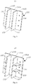
Fig. 1 is a schematic diagram of a battery lower casing in prior art when it is impacted. -
Fig. 2 is a structural schematic diagram of a battery lower casing according to the disclosure. -
Fig. 3 is a structural schematic diagram of a supporting bracket of the battery lower casing as shown inFig. 2 . -
Fig. 4 is a structural schematic diagram of another supporting bracket of the battery lower casing as shown inFig. 2 . -
Fig. 5 is a structural schematic diagram of another supporting bracket of the battery lower casing as shown inFig. 2 . -
Fig. 6 is a structural schematic diagram of another supporting bracket of the battery lower casing as shown inFig. 2 . -
Fig. 7 is a structural schematic diagram of another supporting bracket of the battery lower casing as shown inFig. 2 . -
Fig. 8 is a structural schematic diagram of another supporting bracket of the battery lower casing as shown inFig. 2 . -
Fig. 9 is a schematic diagram of an assembly of the supporting bracket as shown inFig.6 , a fixing beam and a cross beam. -
Fig. 10 is a structural schematic diagram of a battery system according to the disclosure. -
- 1
- battery lower casing;
- 11
- fixing beam;
- 12
- cross beam;
- 121
- end portion;
- 13
- supporting bracket;
- 131
- base plate;
- 131a
- first bearing portion;
- 131b
- second bearing portion;
- 130
- positioning hole;
- 132
- limiting portion;
- 133
- recess;
- 134
- reinforcing portion;
- 135
- connecting portion;
- 14
- bottom plate;
- C
- fixing frame;
- 2
- cover;
- 3
- battery module.
- In the drawings, same components are denoted by same reference numerals. The views are not necessarily plotted in actual proportion in the drawings.
- Various exemplary embodiments, features, and aspects of the disclosure will be described in detail below. In the detailed descriptions, a number of specific details are described to provide a complete understanding of the disclosure. However, it is obvious to the person skilled in the art that the disclosure may be implemented without some of these specific details. The following descriptions of the embodiments merely intend to provide better understanding of the disclosure by illustrating examples of the disclosure. In the drawings and the descriptions below, at least some of well-known structures and techniques are not shown to avoid unnecessarily obscuring the disclosure. For clarity, some structural dimensions may be exaggerated. Furthermore, the features, structures, or characteristics described hereinafter may be combined in any suitable manner in one or more embodiments.
- The orientation indicated in the following description refer to directions shown in the drawings, and are not intended to limit the specific structure of the disclosure. In the description of the disclosure, it should be noted that, unless otherwise stated, the terms "installation" and "connect" are to be understood broadly, and may be, for example, a fixed connection, a disassemble connection, or an integral connection; they can be connected directly or indirectly through an intermediate medium. The specific meaning of the above terms in the disclosure can be understood by the person skilled in the art according to actual circumstance. Moreover, the terms "first", "second", and the like are configured for descriptive purposes only and are not to be construed as indicating or implying relative importance or number of relative features. Therefore, a feature defined with the terms "first" and "second" may explicitly or implicitly include at least one of the feature.
- As shown in
Fig. 1 , in a battery lower casing of prior art, afixing beam 11 and across beam 12 are connected through fixing frames C. The fixing frame C may be an L-shaped or triangular support. One edge of the fixing frame C is connected with thecross beam 12, and another edge is connected to thefixing beam 11. One or more fixing frames C are respectively disposed on both sides of thecross beam 12. Since the fixing frames C on both sides of thecross beam 12 are independently connected to thefixing beam 11, when the batterylower casing 1 receives a lateral impact force F from outside, the respective fixing frames C on both sides may be easily turned outward relative to thefixing beam 11. Thereby, the impactedcross beam 12 is directly in contact with the fixingbeam 11 or even penetrates thefixing beam 11, such that the impact energy cannot be effectively absorbed, and severe inner deformation of the battery system and even major safety accident may occur. - To this end, the disclosure provides a battery
lower casing 1 which has at least good impact resistance. The battery lower casing and the battery system according to embodiments of the disclosure are described in detail below with reference toFig. 2 to Fig 10 . - Referring to
Fig. 2 andFig. 3 , a batterylower casing 1 according to an embodiment of the disclosure includes: a plurality of fixingbeams 11, across beam 12, a supportingbracket 13 and abottom plate 14. - The fixing beams 11 are sequentially connected end to end, and fixed to the
bottom plate 14. The cross beams 12 are disposed between the oppositely disposed fixing beams 11. - The
bottom plate 14 is a plate made of aluminum alloy or carbon steel. Optionally, the fixingbeam 11 and thecross beam 12 can be aluminum alloy profiles, or may be made of materials such as carbon steel, aluminum alloy, magnesium alloy, aluminum magnesium alloy or the like. Their molding process includes, but not limited to, for example die casting, extrusion, casting and the like. The fixing beams 11 can be integrally formed through welding, riveting or screws such that the batterylower casing 1 will have reduced weight while satisfying its structural strength. - The supporting
bracket 13 includes abase plate 131 and limitingportions 132, wherein the limitingportions 132 are connected to thebase plate 131 and disposed opposite to each other. Thebase plate 131 and the oppositely disposed limitingportions 132 enclose and form arecess 133. Thebase plate 131 is connected to thefixing beam 11 and anend portion 121 of thecross beam 12 adjacent to thefixing beam 11 is embedded in therecess 133 such that thecross beam 12 is connected to thefixing beam 11. - The supporting
bracket 13 can be made of a metal material such as carbon steel, aluminum alloy, magnesium alloy, aluminum magnesium alloy and the like. Its molding process includes, but not limited to, for example die casting, extrusion, casting and the like. Thebase plate 131 of the supportingbracket 13 and thefixing beam 11 may be connected through welding, riveting or bolts. Theend portion 121 of thecross beam 12 extends into therecess 133 and is welded to the limitingportion 132. - According to embodiments of the disclosure, at least a portion of the
base plate 131 and the oppositely disposed limitingportions 132 enclose and form arecess 133 which surrounds theend portion 121 of thecross beam 12, such that the fixingbeam 11 and thecross beam 12 are connected to form a whole structure. When the batterylower casing 1 is subjected to a lateral impact force from outside, the supportingbracket 13 can generally absorb the lateral impact force without being split, and the lateral impact force is transmitted back and forth between the oppositely disposed fixingbeams 11 through thecross beam 12 and finally scattered and attenuated. Also, since thebase plate 131 is located between thecross beam 12 and thefixing beam 11, thecross beam 12 can be prevented from penetrating thefixing beam 11 during the impact, and the impact resistance of the batterylower casing 1 is improved. - The battery
lower casing 1 according to the embodiment of the disclosure provides the supportingbracket 13 between the fixingbeam 11 and thecross beam 12. Thebase plate 131 of the supportingbracket 13 is connected to thefixing beam 11, and thecross beam 12 is embedded in therecess 133 which is enclosed by thebase plate 131 and the oppositely disposed limitingportions 132. Therefore, the impact force on the batterylower casing 1 can be scattered and attenuated, the impact resistance of the batterylower casing 1 can be improved, and the batterylower casing 1 has a simple structure and can be manufactured conveniently. - Specific structure of the supporting
bracket 13 will be described in further detail below with reference to the accompanying drawings. - Referring to
Fig. 3 , thebase plate 131 includes afirst bearing portion 131a andsecond bearing portions 131b. Thefirst bearing portion 131a and the oppositely disposed limitingportions 132 enclose and form therecess 133. Thesecond bearing portions 131b are located at two outer sides of therecess 133. - Optionally, the
base plate 131 is a planar plate. Thebase plate 131 is welded to thefixing beam 11. In order to ensure the connection reliability, thesecond bearing portion 131b may be provided with apositioning hole 130 such that thesecond bearing portion 131b can be riveted or screwed to thefixing beam 11. The connection strength between thebase plate 131 and thefixing beam 11 is improved. - Since the
first bearing portion 131a of thebase plate 131 and the oppositely disposed limitingportions 132 enclose and form therecess 133 and thesecond bearing portions 131b are located at two outer sides of therecess 133, the mounting area of thebase plate 131 and thefixing beam 11 is larger than the cross-sectional area of thecross beam 12, and it is not easy for the supportingbracket 13 to turn toward either side of thecross beam 12 when the supportingbracket 13 is subjected to an impact force from outside. The impact force on the batterylower casing 1 can be advantageously absorbed and scattered, and the impact resistance of the batterylower casing 1 is further improved. -
Fig. 4 shows another supportingbracket 13 which is similar in structure to the supportingbracket 13 shown inFig. 2 , except that a reinforcingportion 134 is disposed between thesecond bearing portion 131b and the limitingportion 132. Thereby, the structural rigidity and strength of the supportingbracket 13 are improved. - The reinforcing
portion 134 is a polygonal plate. One edge of the reinforcingportion 134 is connected to the limitingportion 132, and another edge is connected to thesecond bearing portion 131b. There may be one or more reinforcingportions 134. Two or more reinforcingportions 134 are spaced apart to prevent the limitingportion 132 from being locally deformed. Optionally, the number of the reinforcingportions 134 is the same on each outer sides of therecess 133. It ensures the force balance of the supportingbracket 13 on both sides of thecross beam 12, prevents the limitingportion 132 from overturning, and improves the structural rigidity and strength of the supportingbracket 13. Furthermore, the impact resistance of the batterylower casing 1 is improved. -
Fig. 5 shows another supportingbracket 13 which is similar in structure to the supportingbracket 13 shown inFig. 4 , except for the structure of the reinforcingportion 134. - As shown in
Fig. 5 , the reinforcingportion 134 connects an end portion of thesecond bearing portion 131b and an end portion of the limitingportion 132, so that the reinforcingportion 134, thesecond bearing portion 131b and the limitingportion 132 form a hollow triangular prism structure. The structural rigidity and strength of the supportingbracket 13 are further improved with respect to the reinforcingportion 134 inFig. 4 . -
Fig. 6 shows another supportingbracket 13 which is similar in structure to the supportingbracket 13 shown inFig. 5 , except that thefirst bearing portion 131a has a thickness larger than that of thesecond bearing portion 131b and thefirst bearing portion 131a is hollow inside. - When the supporting
bracket 13 is subjected to an impact force from outside, thecross beam 12 repeatedly hits thefirst bearing portion 131a. When thefirst bearing portion 131a has an increased thickness and is hollow inside, thebase plate 131 can bear an increased repeated impact force from theend portion 121 of thecross beam 12, and the structural rigidity and strength of the supportingbracket 13 are improved. -
Fig. 7 shows another supportingbracket 13 which is similar in structure to the supportingbracket 13 shown inFig. 2 , except that the supportingbracket 13 further includes connectingportions 135 which are connected to thebase plate 131 and disposed opposite to each other. The connectingportions 135 and the limitingportions 132 are alternately connected end to end to form a ring structure. - Therefore, the oppositely disposed connecting
portions 135 can restrict thecross beam 12 from swinging up and down along therecess 133, and thereby the connection strength between thecross beam 12 and the limitingportion 132 can be further improved. - Optionally, the ring structure has a box shape with an opening, and the connection between the connecting
portion 135 and the limitingportion 132 is smoothly transitioned to prevent scratching of operators. - Optionally, a reinforcing
portion 134 is disposed between thesecond bearing portion 131b and the limitingportion 132. The reinforcingportion 134 can be, for example, a polygonal plate as shown inFig. 4 . Therefore, the structural strength and rigidity of the supportingbracket 13 can be further improved, and thereby the impact resistance of the batterylower casing 1 can be improved. -
Fig. 8 shows another supportingbracket 13 which is similar in structure to the supportingbracket 13 shown inFig. 7 , except that thebase plate 131 is a curved plate. The curved plate may be a wave-shaped plate or an arced plate. Accordingly, the impact force transmitted between thecross beam 12 and the oppositely disposed fixingbeams 11 can be buffered, the time by which the impact force is scattered and attenuated can be shortened, and the impact resistance of the batterylower casing 1 can be improved. - It can be understood that the supporting
bracket 13 can also be any combination of the above features. For example, thebase plates 131 inFig. 3 to Fig. 7 can also be a curved plate, which will not be described in detail here. - Referring to
Fig. 9 , since there are inevitable manufacturing tolerances in thefixing beam 11 and thecross beam 12, a mounting gap exists between thecross beam 12 and the fixingcross beam 12. The supportingbracket 13 can compensate for the mounting gap. Thereby, the manufacture feasibility of the batterylower casing 1 can be improved. - Specifically, in any of the supporting
brackets 13 as described above, therecess 133 has a width W1, and theend portion 121 of thecross beam 12 has a width W2. There is a difference t between the widths of therecess 133 and theend portion 121 of thecross beam 12, which satisfies the following condition: 1mm≤t≤3mm. If t is not in the above range, the fitting of thecross beam 12 with therecess 133 may be too tight for installation, or too loose such that the welding strength of thecross beam 12 and the limitingportion 132 may be adversely affected. - Furthermore, there is a distance h between the
end portion 121 of thecross beam 12 and a bottom of therecess 133, which satisfies the following condition: 1mm≤h≤5 mm. If h is not the above range, the gap between thecross beam 12 and the bottom of therecess 133 may be too small for installation, or too large such that the connecting strength of thecross beam 12 and the supportingbracket 13 may be adversely affected. - Referring to
Fig. 10 , embodiments of the disclosure further provide a battery system including any of the batterylower casings 1 as described above, a cover 2, and a plurality ofbattery modules 3. - The cover 2 covers the fixing beams 11 of the battery
lower casing 1, and forms at least two accommodating chambers with thecross beam 12. Thebattery modules 3 are accommodated in the accommodating chambers. The greater the number of cross beams 12, the greater the number of accommodating chambers, in whichmore battery modules 3 can be accommodated. - The battery system according to embodiments of the disclosure adopts the battery
lower casing 1 as described above, which can reduce degree of potential damage inside the battery system and improve the safety and reliability of the battery system. When the battery system is applies in a new energy vehicle, it is beneficial to improve the anti-side-collision performance of the new energy vehicle. Thereby, the spontaneous combustion and electric leakage accidents of the battery system can be avoided or retarded, and more valuable rescue time for life and property can be provided. - Although the disclosure has been described with reference to the preferred embodiments, various modifications may be made to the disclosure and components may be replaced with equivalents without departing from the scope of the disclosure. In particular, the technical features mentioned in the various embodiments can be combined in any manner as long as there is no structural conflict. The disclosure is not limited to the specific embodiments disclosed herein, but comprises all technical solutions falling within the scope of the claims.
Claims (10)
- A battery lower casing (1), characterized in that the battery lower casing (1) comprising:a bottom plate (14);a plurality of fixing beams (11) sequentially connected end to end and fixed to the bottom plate (14);a cross beam (12) disposed between the oppositely disposed fixing beams (11); anda supporting bracket (13) comprising a base plate (131) and limiting portions (132), wherein the limiting portions (132) are connected to the base plate (131) and disposed opposite to each other, the base plate (131) and the oppositely disposed limiting portions (132) enclose and form a recess (133), the base plate (131) is connected to the fixing beam (11) and an end portion (121) of the cross beam (12) adjacent to the fixing beam (11) is embedded in the recess (133) such that the cross beam (12) is connected to the fixing beam (11).
- The battery lower casing (1) according to claim 1, characterized in that, the base plate (131) comprises a first bearing portion (131a) and second bearing portions (131b), wherein the first bearing portion (131a) and the oppositely disposed limiting portions (132) enclose and form the recess (133), and the second bearing portions (131b) are located at two outer sides of the recess (133).
- The battery lower casing (1) according to claim 2, characterized in that, a reinforcing portion (134) is disposed between the second bearing portion (131b) and the limiting portion (132).
- The battery lower casing (1) according to claim 3, characterized in that, the reinforcing portion (134) is a polygonal plate, wherein one edge of the reinforcing portion (134) is connected to the limiting portion (132), and another edge is connected to the second bearing portion (131b).
- The battery lower casing (1) according to claim 3, characterized in that, the reinforcing portion (134), the second bearing portion (131b) and the limiting portion (132) form a hollow triangular prism structure.
- The battery lower casing (1) according to claim 5, characterized in that, the first bearing portion (131a) has a thickness larger than that of the second bearing portion (131b), and the first bearing portion (131a) is hollow inside.
- The battery lower casing (1) according to claim 2 or 3, characterized in that, the supporting bracket (13) further comprises connecting portions (135) which are connected to the base plate (131) and disposed opposite to each other, and the connecting portions (135) and the limiting portions (132) are alternately connected end to end to form a ring structure.
- The battery lower casing (1) according to claim 1, characterized in that, the base plate (131) is a planar plate or a curved plate.
- The battery lower casing (1) according to claim 1, characterized in that, the recess (133) has a width W1, the end portion (121) of the cross beam (12) has a width W2, and there is a difference t between the widths of the recess (133) and the end portion (121), which satisfies 1mm≤t≤3mm; and
there is a distance h between the end portion (121) of the cross beam (12) and a bottom of the recess (133), which satisfies 1mm≤h≤5 mm. - A battery system, characterized in that, the battery system comprising:a battery lower casing (1) according to any of claims 1 to 9;a cover (2) which covers the fixing beams (11) of the battery lower casing (1) and forms at least two accommodating chambers with the cross beam (12); anda plurality of battery modules (3) accommodated in the accommodating chambers.
Applications Claiming Priority (1)
| Application Number | Priority Date | Filing Date | Title |
|---|---|---|---|
| CN201921098475.3U CN210110876U (en) | 2019-07-15 | 2019-07-15 | Battery lower box body and battery system |
Publications (2)
| Publication Number | Publication Date |
|---|---|
| EP3767700A1 true EP3767700A1 (en) | 2021-01-20 |
| EP3767700B1 EP3767700B1 (en) | 2021-07-21 |
Family
ID=67847654
Family Applications (1)
| Application Number | Title | Priority Date | Filing Date |
|---|---|---|---|
| EP19195137.5A Active EP3767700B1 (en) | 2019-07-15 | 2019-09-03 | Battery lower casing and battery system |
Country Status (4)
| Country | Link |
|---|---|
| US (1) | US11177527B2 (en) |
| EP (1) | EP3767700B1 (en) |
| CN (1) | CN210110876U (en) |
| WO (1) | WO2021008283A1 (en) |
Families Citing this family (22)
| Publication number | Priority date | Publication date | Assignee | Title |
|---|---|---|---|---|
| CN210110876U (en) | 2019-07-15 | 2020-02-21 | 江苏时代新能源科技有限公司 | Battery lower box body and battery system |
| KR102484991B1 (en) * | 2020-10-19 | 2023-01-04 | 주식회사 포스코 | Battery case |
| EP4044329B1 (en) * | 2020-12-25 | 2024-02-14 | Contemporary Amperex Technology Co., Limited | Battery box body, battery, electric device, and method and device for manufacturing box body |
| KR102884911B1 (en) * | 2021-01-22 | 2025-11-13 | 주식회사 엘지에너지솔루션 | A Battery Module Equipped With A Fire Spread Prevention Structure And A Battery Pack Including It |
| WO2022230344A1 (en) * | 2021-04-29 | 2022-11-03 | アイシン軽金属株式会社 | Onboard battery case structure |
| JPWO2022230345A1 (en) * | 2021-04-29 | 2022-11-03 | ||
| JP7732767B2 (en) * | 2021-04-29 | 2025-09-02 | アイシン軽金属株式会社 | Fastening structure for strength members of battery cases |
| CN117083193A (en) * | 2021-04-29 | 2023-11-17 | 爱信轻金属株式会社 | Strength components for vehicle battery cases and their mounting structures |
| KR20230065641A (en) * | 2021-11-05 | 2023-05-12 | 주식회사 포스코 | Cross member for battery case and battery case |
| CN114497854A (en) * | 2021-12-21 | 2022-05-13 | 极氪汽车(宁波杭州湾新区)有限公司 | Battery package box structure |
| CN114388967A (en) * | 2021-12-21 | 2022-04-22 | 威睿电动汽车技术(宁波)有限公司 | Liquid-cooled battery tray and battery box |
| JP7528973B2 (en) * | 2022-03-30 | 2024-08-06 | トヨタ自動車株式会社 | Battery case |
| CN114454772B (en) * | 2022-04-13 | 2022-06-28 | 中国重汽集团济南动力有限公司 | A battery locking device and a heavy-duty electric commercial vehicle for battery replacement |
| CN117638352A (en) * | 2022-08-11 | 2024-03-01 | 福特全球技术公司 | Vehicle battery protection frame and corresponding vehicle |
| WO2024044980A1 (en) * | 2022-08-30 | 2024-03-07 | 宁德时代新能源科技股份有限公司 | Case, battery, and electric device |
| WO2024060258A1 (en) * | 2022-09-23 | 2024-03-28 | 宁德时代新能源科技股份有限公司 | Box body, battery and vehicle |
| FR3140481B1 (en) * | 2022-10-03 | 2025-02-14 | Psa Automobiles Sa | DEVICE FOR RECEIVING BATTERY MODULES INTENDED TO POWER AN ELECTRICAL COMPONENT |
| WO2024103359A1 (en) * | 2022-11-17 | 2024-05-23 | 宁德时代新能源科技股份有限公司 | Tray and battery restraint device |
| JP7652180B2 (en) * | 2022-12-01 | 2025-03-27 | トヨタ自動車株式会社 | Power storage device |
| EP4531182A1 (en) * | 2024-02-06 | 2025-04-02 | Constellium UK Limited | Assembly for battery holder, and battery holder for transport vehicle |
| GB2643789A (en) * | 2024-09-03 | 2026-03-04 | Jaguar Land Rover Ltd | Connector for battery frame of vehicle |
| GB2643797A (en) * | 2024-09-03 | 2026-03-04 | Jaguar Land Rover Ltd | Crossmember end adapter |
Citations (4)
| Publication number | Priority date | Publication date | Assignee | Title |
|---|---|---|---|---|
| US953600A (en) * | 1909-03-05 | 1910-03-29 | Noah S Edens | Tide-motor. |
| WO2015149660A1 (en) * | 2014-03-31 | 2015-10-08 | Byd Company Limited | Battery accommodating assembly, battery module and vehicle having the same |
| US20180050607A1 (en) * | 2016-08-17 | 2018-02-22 | Shape Corp. | Battery support and protection structure for a vehicle |
| CN109768200A (en) * | 2019-03-29 | 2019-05-17 | 蜂巢能源科技有限公司 | battery pack case |
Family Cites Families (13)
| Publication number | Priority date | Publication date | Assignee | Title |
|---|---|---|---|---|
| US5881517A (en) * | 1997-08-26 | 1999-03-16 | Universal Consolidated Methods, Inc. | Rest room partition mounting brackets |
| KR20060037598A (en) | 2004-10-28 | 2006-05-03 | 삼성에스디아이 주식회사 | Battery module |
| US20140196394A1 (en) * | 2013-01-11 | 2014-07-17 | Chatsworth Products, Inc. | Modular thermal isolation barrier for data processing equipment structure |
| GB2541203B (en) * | 2015-08-11 | 2019-02-06 | Jaguar Land Rover Ltd | Apparatus for supporting a battery with integrated cooling channels |
| US9533600B1 (en) | 2015-09-03 | 2017-01-03 | GM Global Technology Operations LLC | Structurally integrated propulsion battery |
| CN205050889U (en) | 2015-09-28 | 2016-02-24 | 浙江天能能源科技有限公司 | Double -deck panel beating battery box |
| DE102016110787A1 (en) * | 2016-06-13 | 2017-12-14 | Dr. Ing. H.C. F. Porsche Aktiengesellschaft | Battery housing of a traction battery of a motor vehicle |
| DE102016121254B4 (en) | 2016-11-07 | 2020-12-24 | Benteler Automobiltechnik Gmbh | Battery tray with tolerance compensation element |
| CN207474545U (en) | 2017-12-01 | 2018-06-08 | 郑州比克电池有限公司 | A kind of battery pack sheet metal box body for improving stress |
| CN108461685A (en) | 2018-04-13 | 2018-08-28 | 爱驰汽车有限公司 | Battery pack and its Battery case |
| CN209658262U (en) | 2019-03-19 | 2019-11-19 | 宁波吉利汽车研究开发有限公司 | a battery pack |
| CN210110876U (en) | 2019-07-15 | 2020-02-21 | 江苏时代新能源科技有限公司 | Battery lower box body and battery system |
| CN110571378A (en) | 2019-08-29 | 2019-12-13 | 广汽新能源汽车有限公司 | Battery case and battery system |
-
2019
- 2019-07-15 CN CN201921098475.3U patent/CN210110876U/en active Active
- 2019-08-27 US US16/552,298 patent/US11177527B2/en active Active
- 2019-09-03 EP EP19195137.5A patent/EP3767700B1/en active Active
-
2020
- 2020-06-12 WO PCT/CN2020/095758 patent/WO2021008283A1/en not_active Ceased
Patent Citations (4)
| Publication number | Priority date | Publication date | Assignee | Title |
|---|---|---|---|---|
| US953600A (en) * | 1909-03-05 | 1910-03-29 | Noah S Edens | Tide-motor. |
| WO2015149660A1 (en) * | 2014-03-31 | 2015-10-08 | Byd Company Limited | Battery accommodating assembly, battery module and vehicle having the same |
| US20180050607A1 (en) * | 2016-08-17 | 2018-02-22 | Shape Corp. | Battery support and protection structure for a vehicle |
| CN109768200A (en) * | 2019-03-29 | 2019-05-17 | 蜂巢能源科技有限公司 | battery pack case |
Also Published As
| Publication number | Publication date |
|---|---|
| CN210110876U (en) | 2020-02-21 |
| US20210020877A1 (en) | 2021-01-21 |
| WO2021008283A1 (en) | 2021-01-21 |
| EP3767700B1 (en) | 2021-07-21 |
| US11177527B2 (en) | 2021-11-16 |
Similar Documents
| Publication | Publication Date | Title |
|---|---|---|
| EP3767700A1 (en) | Battery lower casing and battery system | |
| KR102859533B1 (en) | Thermal systems for battery electric vehicles | |
| US8551632B2 (en) | Battery cooling system | |
| KR20240154609A (en) | Explosion-proof valves, batteries, battery modules, battery packs and vehicles | |
| EP3930025B1 (en) | Battery module, battery pack, and vehicle | |
| US20240347837A1 (en) | Edge beam for battery tray, battery tray, battery pack and vehicle | |
| CN218229134U (en) | Frame assembly for vehicle and vehicle with frame assembly | |
| CN110171376B (en) | Front engine room collision energy-absorbing structure | |
| JP2023006069A (en) | Support device for vehicle battery pack and electric track | |
| CN108162900B (en) | Bumper assembly for a motor vehicle | |
| EP3731301A1 (en) | Energy storage device | |
| EP4718607A1 (en) | Battery pack and vehicle | |
| US20240313318A1 (en) | Battery pack and electric apparatus | |
| US20240363947A1 (en) | Battery pack and electric apparatus | |
| US20240304926A1 (en) | Battery pack and electric apparatus | |
| JP2025124751A (en) | Power storage device | |
| CN206584985U (en) | Battery bag shielded frame and battery bag | |
| US12115847B2 (en) | Battery housing assembly having strike bar | |
| US9276299B2 (en) | Vehicle | |
| CN220209157U (en) | Battery pack box, battery system and new energy vehicle | |
| CN220021389U (en) | Battery pack and vehicle | |
| CN117832724B (en) | Battery pack and vehicle | |
| CN222146436U (en) | Battery pack and vehicle | |
| CN212659630U (en) | A end backplate, battery package and vehicle for battery package | |
| CN224036508U (en) | Battery devices and vehicles |
Legal Events
| Date | Code | Title | Description |
|---|---|---|---|
| STAA | Information on the status of an ep patent application or granted ep patent |
Free format text: STATUS: EXAMINATION IS IN PROGRESS |
|
| PUAI | Public reference made under article 153(3) epc to a published international application that has entered the european phase |
Free format text: ORIGINAL CODE: 0009012 |
|
| 17P | Request for examination filed |
Effective date: 20200423 |
|
| AK | Designated contracting states |
Kind code of ref document: A1 Designated state(s): AL AT BE BG CH CY CZ DE DK EE ES FI FR GB GR HR HU IE IS IT LI LT LU LV MC MK MT NL NO PL PT RO RS SE SI SK SM TR |
|
| AX | Request for extension of the european patent |
Extension state: BA ME |
|
| REG | Reference to a national code |
Ref country code: DE Ref legal event code: R079 Ref document number: 602019006238 Country of ref document: DE Free format text: PREVIOUS MAIN CLASS: H01M0002100000 Ipc: H01M0050200000 |
|
| GRAP | Despatch of communication of intention to grant a patent |
Free format text: ORIGINAL CODE: EPIDOSNIGR1 |
|
| STAA | Information on the status of an ep patent application or granted ep patent |
Free format text: STATUS: GRANT OF PATENT IS INTENDED |
|
| RIC1 | Information provided on ipc code assigned before grant |
Ipc: H01M 50/20 20210101AFI20210129BHEP |
|
| INTG | Intention to grant announced |
Effective date: 20210216 |
|
| GRAS | Grant fee paid |
Free format text: ORIGINAL CODE: EPIDOSNIGR3 |
|
| GRAA | (expected) grant |
Free format text: ORIGINAL CODE: 0009210 |
|
| STAA | Information on the status of an ep patent application or granted ep patent |
Free format text: STATUS: THE PATENT HAS BEEN GRANTED |
|
| AK | Designated contracting states |
Kind code of ref document: B1 Designated state(s): AL AT BE BG CH CY CZ DE DK EE ES FI FR GB GR HR HU IE IS IT LI LT LU LV MC MK MT NL NO PL PT RO RS SE SI SK SM TR |
|
| REG | Reference to a national code |
Ref country code: GB Ref legal event code: FG4D |
|
| REG | Reference to a national code |
Ref country code: CH Ref legal event code: EP |
|
| REG | Reference to a national code |
Ref country code: DE Ref legal event code: R096 Ref document number: 602019006238 Country of ref document: DE |
|
| REG | Reference to a national code |
Ref country code: AT Ref legal event code: REF Ref document number: 1413447 Country of ref document: AT Kind code of ref document: T Effective date: 20210815 |
|
| REG | Reference to a national code |
Ref country code: IE Ref legal event code: FG4D |
|
| REG | Reference to a national code |
Ref country code: LT Ref legal event code: MG9D |
|
| REG | Reference to a national code |
Ref country code: NL Ref legal event code: MP Effective date: 20210721 |
|
| REG | Reference to a national code |
Ref country code: AT Ref legal event code: MK05 Ref document number: 1413447 Country of ref document: AT Kind code of ref document: T Effective date: 20210721 |
|
| PG25 | Lapsed in a contracting state [announced via postgrant information from national office to epo] |
Ref country code: NL Free format text: LAPSE BECAUSE OF FAILURE TO SUBMIT A TRANSLATION OF THE DESCRIPTION OR TO PAY THE FEE WITHIN THE PRESCRIBED TIME-LIMIT Effective date: 20210721 Ref country code: PT Free format text: LAPSE BECAUSE OF FAILURE TO SUBMIT A TRANSLATION OF THE DESCRIPTION OR TO PAY THE FEE WITHIN THE PRESCRIBED TIME-LIMIT Effective date: 20211122 Ref country code: NO Free format text: LAPSE BECAUSE OF FAILURE TO SUBMIT A TRANSLATION OF THE DESCRIPTION OR TO PAY THE FEE WITHIN THE PRESCRIBED TIME-LIMIT Effective date: 20211021 Ref country code: HR Free format text: LAPSE BECAUSE OF FAILURE TO SUBMIT A TRANSLATION OF THE DESCRIPTION OR TO PAY THE FEE WITHIN THE PRESCRIBED TIME-LIMIT Effective date: 20210721 Ref country code: AT Free format text: LAPSE BECAUSE OF FAILURE TO SUBMIT A TRANSLATION OF THE DESCRIPTION OR TO PAY THE FEE WITHIN THE PRESCRIBED TIME-LIMIT Effective date: 20210721 Ref country code: BG Free format text: LAPSE BECAUSE OF FAILURE TO SUBMIT A TRANSLATION OF THE DESCRIPTION OR TO PAY THE FEE WITHIN THE PRESCRIBED TIME-LIMIT Effective date: 20211021 Ref country code: LT Free format text: LAPSE BECAUSE OF FAILURE TO SUBMIT A TRANSLATION OF THE DESCRIPTION OR TO PAY THE FEE WITHIN THE PRESCRIBED TIME-LIMIT Effective date: 20210721 Ref country code: RS Free format text: LAPSE BECAUSE OF FAILURE TO SUBMIT A TRANSLATION OF THE DESCRIPTION OR TO PAY THE FEE WITHIN THE PRESCRIBED TIME-LIMIT Effective date: 20210721 Ref country code: SE Free format text: LAPSE BECAUSE OF FAILURE TO SUBMIT A TRANSLATION OF THE DESCRIPTION OR TO PAY THE FEE WITHIN THE PRESCRIBED TIME-LIMIT Effective date: 20210721 Ref country code: ES Free format text: LAPSE BECAUSE OF FAILURE TO SUBMIT A TRANSLATION OF THE DESCRIPTION OR TO PAY THE FEE WITHIN THE PRESCRIBED TIME-LIMIT Effective date: 20210721 Ref country code: FI Free format text: LAPSE BECAUSE OF FAILURE TO SUBMIT A TRANSLATION OF THE DESCRIPTION OR TO PAY THE FEE WITHIN THE PRESCRIBED TIME-LIMIT Effective date: 20210721 |
|
| PG25 | Lapsed in a contracting state [announced via postgrant information from national office to epo] |
Ref country code: PL Free format text: LAPSE BECAUSE OF FAILURE TO SUBMIT A TRANSLATION OF THE DESCRIPTION OR TO PAY THE FEE WITHIN THE PRESCRIBED TIME-LIMIT Effective date: 20210721 Ref country code: LV Free format text: LAPSE BECAUSE OF FAILURE TO SUBMIT A TRANSLATION OF THE DESCRIPTION OR TO PAY THE FEE WITHIN THE PRESCRIBED TIME-LIMIT Effective date: 20210721 Ref country code: GR Free format text: LAPSE BECAUSE OF FAILURE TO SUBMIT A TRANSLATION OF THE DESCRIPTION OR TO PAY THE FEE WITHIN THE PRESCRIBED TIME-LIMIT Effective date: 20211022 |
|
| REG | Reference to a national code |
Ref country code: DE Ref legal event code: R097 Ref document number: 602019006238 Country of ref document: DE |
|
| PG25 | Lapsed in a contracting state [announced via postgrant information from national office to epo] |
Ref country code: DK Free format text: LAPSE BECAUSE OF FAILURE TO SUBMIT A TRANSLATION OF THE DESCRIPTION OR TO PAY THE FEE WITHIN THE PRESCRIBED TIME-LIMIT Effective date: 20210721 |
|
| REG | Reference to a national code |
Ref country code: BE Ref legal event code: MM Effective date: 20210930 |
|
| PLBE | No opposition filed within time limit |
Free format text: ORIGINAL CODE: 0009261 |
|
| STAA | Information on the status of an ep patent application or granted ep patent |
Free format text: STATUS: NO OPPOSITION FILED WITHIN TIME LIMIT |
|
| PG25 | Lapsed in a contracting state [announced via postgrant information from national office to epo] |
Ref country code: SM Free format text: LAPSE BECAUSE OF FAILURE TO SUBMIT A TRANSLATION OF THE DESCRIPTION OR TO PAY THE FEE WITHIN THE PRESCRIBED TIME-LIMIT Effective date: 20210721 Ref country code: SK Free format text: LAPSE BECAUSE OF FAILURE TO SUBMIT A TRANSLATION OF THE DESCRIPTION OR TO PAY THE FEE WITHIN THE PRESCRIBED TIME-LIMIT Effective date: 20210721 Ref country code: RO Free format text: LAPSE BECAUSE OF FAILURE TO SUBMIT A TRANSLATION OF THE DESCRIPTION OR TO PAY THE FEE WITHIN THE PRESCRIBED TIME-LIMIT Effective date: 20210721 Ref country code: MC Free format text: LAPSE BECAUSE OF FAILURE TO SUBMIT A TRANSLATION OF THE DESCRIPTION OR TO PAY THE FEE WITHIN THE PRESCRIBED TIME-LIMIT Effective date: 20210721 Ref country code: EE Free format text: LAPSE BECAUSE OF FAILURE TO SUBMIT A TRANSLATION OF THE DESCRIPTION OR TO PAY THE FEE WITHIN THE PRESCRIBED TIME-LIMIT Effective date: 20210721 Ref country code: CZ Free format text: LAPSE BECAUSE OF FAILURE TO SUBMIT A TRANSLATION OF THE DESCRIPTION OR TO PAY THE FEE WITHIN THE PRESCRIBED TIME-LIMIT Effective date: 20210721 Ref country code: AL Free format text: LAPSE BECAUSE OF FAILURE TO SUBMIT A TRANSLATION OF THE DESCRIPTION OR TO PAY THE FEE WITHIN THE PRESCRIBED TIME-LIMIT Effective date: 20210721 |
|
| 26N | No opposition filed |
Effective date: 20220422 |
|
| PG25 | Lapsed in a contracting state [announced via postgrant information from national office to epo] |
Ref country code: LU Free format text: LAPSE BECAUSE OF NON-PAYMENT OF DUE FEES Effective date: 20210903 Ref country code: IT Free format text: LAPSE BECAUSE OF FAILURE TO SUBMIT A TRANSLATION OF THE DESCRIPTION OR TO PAY THE FEE WITHIN THE PRESCRIBED TIME-LIMIT Effective date: 20210721 Ref country code: IE Free format text: LAPSE BECAUSE OF NON-PAYMENT OF DUE FEES Effective date: 20210903 Ref country code: BE Free format text: LAPSE BECAUSE OF NON-PAYMENT OF DUE FEES Effective date: 20210930 |
|
| REG | Reference to a national code |
Ref country code: CH Ref legal event code: PL |
|
| P01 | Opt-out of the competence of the unified patent court (upc) registered |
Effective date: 20230522 |
|
| PG25 | Lapsed in a contracting state [announced via postgrant information from national office to epo] |
Ref country code: CY Free format text: LAPSE BECAUSE OF FAILURE TO SUBMIT A TRANSLATION OF THE DESCRIPTION OR TO PAY THE FEE WITHIN THE PRESCRIBED TIME-LIMIT Effective date: 20210721 |
|
| PG25 | Lapsed in a contracting state [announced via postgrant information from national office to epo] |
Ref country code: LI Free format text: LAPSE BECAUSE OF NON-PAYMENT OF DUE FEES Effective date: 20220930 Ref country code: HU Free format text: LAPSE BECAUSE OF FAILURE TO SUBMIT A TRANSLATION OF THE DESCRIPTION OR TO PAY THE FEE WITHIN THE PRESCRIBED TIME-LIMIT; INVALID AB INITIO Effective date: 20190903 Ref country code: CH Free format text: LAPSE BECAUSE OF NON-PAYMENT OF DUE FEES Effective date: 20220930 |
|
| PG25 | Lapsed in a contracting state [announced via postgrant information from national office to epo] |
Ref country code: MK Free format text: LAPSE BECAUSE OF FAILURE TO SUBMIT A TRANSLATION OF THE DESCRIPTION OR TO PAY THE FEE WITHIN THE PRESCRIBED TIME-LIMIT Effective date: 20210721 |
|
| PG25 | Lapsed in a contracting state [announced via postgrant information from national office to epo] |
Ref country code: TR Free format text: LAPSE BECAUSE OF FAILURE TO SUBMIT A TRANSLATION OF THE DESCRIPTION OR TO PAY THE FEE WITHIN THE PRESCRIBED TIME-LIMIT Effective date: 20210721 |
|
| PG25 | Lapsed in a contracting state [announced via postgrant information from national office to epo] |
Ref country code: MT Free format text: LAPSE BECAUSE OF FAILURE TO SUBMIT A TRANSLATION OF THE DESCRIPTION OR TO PAY THE FEE WITHIN THE PRESCRIBED TIME-LIMIT Effective date: 20210721 |
|
| PGFP | Annual fee paid to national office [announced via postgrant information from national office to epo] |
Ref country code: DE Payment date: 20250702 Year of fee payment: 7 |
|
| PGFP | Annual fee paid to national office [announced via postgrant information from national office to epo] |
Ref country code: GB Payment date: 20250703 Year of fee payment: 7 |
|
| PGFP | Annual fee paid to national office [announced via postgrant information from national office to epo] |
Ref country code: FR Payment date: 20250703 Year of fee payment: 7 |