EP3767428A1 - Mobile terminal, antenna control method and storage medium - Google Patents
Mobile terminal, antenna control method and storage medium Download PDFInfo
- Publication number
- EP3767428A1 EP3767428A1 EP20163355.9A EP20163355A EP3767428A1 EP 3767428 A1 EP3767428 A1 EP 3767428A1 EP 20163355 A EP20163355 A EP 20163355A EP 3767428 A1 EP3767428 A1 EP 3767428A1
- Authority
- EP
- European Patent Office
- Prior art keywords
- antenna
- display screen
- flexible display
- state
- mobile terminal
- Prior art date
- Legal status (The legal status is an assumption and is not a legal conclusion. Google has not performed a legal analysis and makes no representation as to the accuracy of the status listed.)
- Granted
Links
Images





Classifications
-
- G—PHYSICS
- G09—EDUCATION; CRYPTOGRAPHY; DISPLAY; ADVERTISING; SEALS
- G09F—DISPLAYING; ADVERTISING; SIGNS; LABELS OR NAME-PLATES; SEALS
- G09F9/00—Indicating arrangements for variable information in which the information is built-up on a support by selection or combination of individual elements
- G09F9/30—Indicating arrangements for variable information in which the information is built-up on a support by selection or combination of individual elements in which the desired character or characters are formed by combining individual elements
- G09F9/301—Indicating arrangements for variable information in which the information is built-up on a support by selection or combination of individual elements in which the desired character or characters are formed by combining individual elements flexible foldable or roll-able electronic displays, e.g. thin LCD, OLED
-
- H—ELECTRICITY
- H04—ELECTRIC COMMUNICATION TECHNIQUE
- H04M—TELEPHONIC COMMUNICATION
- H04M1/00—Substation equipment, e.g. for use by subscribers
- H04M1/72—Mobile telephones; Cordless telephones, i.e. devices for establishing wireless links to base stations without route selection
- H04M1/724—User interfaces specially adapted for cordless or mobile telephones
-
- G—PHYSICS
- G06—COMPUTING OR CALCULATING; COUNTING
- G06F—ELECTRIC DIGITAL DATA PROCESSING
- G06F1/00—Details not covered by groups G06F3/00 - G06F13/00 and G06F21/00
- G06F1/16—Constructional details or arrangements
- G06F1/1613—Constructional details or arrangements for portable computers
- G06F1/1633—Constructional details or arrangements of portable computers not specific to the type of enclosures covered by groups G06F1/1615 - G06F1/1626
- G06F1/1637—Details related to the display arrangement, including those related to the mounting of the display in the housing
- G06F1/1652—Details related to the display arrangement, including those related to the mounting of the display in the housing the display being flexible, e.g. mimicking a sheet of paper, or rollable
-
- H—ELECTRICITY
- H01—ELECTRIC ELEMENTS
- H01Q—ANTENNAS, i.e. RADIO AERIALS
- H01Q1/00—Details of, or arrangements associated with, antennas
- H01Q1/12—Supports; Mounting means
- H01Q1/22—Supports; Mounting means by structural association with other equipment or articles
- H01Q1/24—Supports; Mounting means by structural association with other equipment or articles with receiving set
- H01Q1/241—Supports; Mounting means by structural association with other equipment or articles with receiving set used in mobile communications, e.g. GSM
- H01Q1/242—Supports; Mounting means by structural association with other equipment or articles with receiving set used in mobile communications, e.g. GSM specially adapted for hand-held use
- H01Q1/243—Supports; Mounting means by structural association with other equipment or articles with receiving set used in mobile communications, e.g. GSM specially adapted for hand-held use with built-in antennas
-
- H—ELECTRICITY
- H01—ELECTRIC ELEMENTS
- H01Q—ANTENNAS, i.e. RADIO AERIALS
- H01Q1/00—Details of, or arrangements associated with, antennas
- H01Q1/12—Supports; Mounting means
- H01Q1/22—Supports; Mounting means by structural association with other equipment or articles
- H01Q1/24—Supports; Mounting means by structural association with other equipment or articles with receiving set
- H01Q1/241—Supports; Mounting means by structural association with other equipment or articles with receiving set used in mobile communications, e.g. GSM
- H01Q1/242—Supports; Mounting means by structural association with other equipment or articles with receiving set used in mobile communications, e.g. GSM specially adapted for hand-held use
- H01Q1/243—Supports; Mounting means by structural association with other equipment or articles with receiving set used in mobile communications, e.g. GSM specially adapted for hand-held use with built-in antennas
- H01Q1/244—Supports; Mounting means by structural association with other equipment or articles with receiving set used in mobile communications, e.g. GSM specially adapted for hand-held use with built-in antennas extendable from a housing along a given path
-
- H—ELECTRICITY
- H04—ELECTRIC COMMUNICATION TECHNIQUE
- H04B—TRANSMISSION
- H04B1/00—Details of transmission systems, not covered by a single one of groups H04B3/00 - H04B13/00; Details of transmission systems not characterised by the medium used for transmission
- H04B1/38—Transceivers, i.e. devices in which transmitter and receiver form a structural unit and in which at least one part is used for functions of transmitting and receiving
- H04B1/40—Circuits
- H04B1/401—Circuits for selecting or indicating operating mode
-
- H—ELECTRICITY
- H04—ELECTRIC COMMUNICATION TECHNIQUE
- H04M—TELEPHONIC COMMUNICATION
- H04M1/00—Substation equipment, e.g. for use by subscribers
- H04M1/02—Constructional features of telephone sets
- H04M1/0202—Portable telephone sets, e.g. cordless phones, mobile phones or bar type handsets
- H04M1/026—Details of the structure or mounting of specific components
-
- H—ELECTRICITY
- H04—ELECTRIC COMMUNICATION TECHNIQUE
- H04M—TELEPHONIC COMMUNICATION
- H04M1/00—Substation equipment, e.g. for use by subscribers
- H04M1/02—Constructional features of telephone sets
- H04M1/0202—Portable telephone sets, e.g. cordless phones, mobile phones or bar type handsets
- H04M1/026—Details of the structure or mounting of specific components
- H04M1/0266—Details of the structure or mounting of specific components for a display module assembly
- H04M1/0268—Details of the structure or mounting of specific components for a display module assembly including a flexible display panel
-
- H—ELECTRICITY
- H04—ELECTRIC COMMUNICATION TECHNIQUE
- H04M—TELEPHONIC COMMUNICATION
- H04M1/00—Substation equipment, e.g. for use by subscribers
- H04M1/02—Constructional features of telephone sets
- H04M1/03—Constructional features of telephone transmitters or receivers, e.g. telephone hand-sets
-
- H—ELECTRICITY
- H04—ELECTRIC COMMUNICATION TECHNIQUE
- H04M—TELEPHONIC COMMUNICATION
- H04M2201/00—Electronic components, circuits, software, systems or apparatus used in telephone systems
- H04M2201/34—Microprocessors
-
- H—ELECTRICITY
- H04—ELECTRIC COMMUNICATION TECHNIQUE
- H04M—TELEPHONIC COMMUNICATION
- H04M2250/00—Details of telephonic subscriber devices
- H04M2250/12—Details of telephonic subscriber devices including a sensor for measuring a physical value, e.g. temperature or motion
Definitions
- This disclosure relates to a field of mobile terminals, and in particular, to a mobile terminal, an antenna control method, and a storage medium.
- the flexible display screen may be expanded to enlarge the screen area when the mobile terminal is used, the flexible display screen may be retracted to reduce the screen area when the mobile terminal is carried, and the size of the flexible display screen is selected according to use environments, so as to make the mobile terminal more convenient.
- the embodiments of the present disclosure provide a mobile terminal, an antenna control method and a storage medium, which can solve a problem that the antenna performance is reduced due to the change of a state of a flexible display screen.
- the technical solution is exemplified as follows.
- a mobile terminal including a body and a flexible display screen disposed on the body; wherein the flexible display screen is configured to be switched between an expanded state in which the flexible display screen is expanded to form a first area and a retracted state in which the flexible display screen is retracted to form a second area, and the first area is larger than the second area.
- a primary antenna is disposed within the body, and a spare antenna for replacing the primary antenna is disposed at an edge of the flexible display screen.
- the flexible display screen is rectangular, and a first edge of the flexible display screen is secured to the body; and the spare antenna is disposed on at least one of a second edge, a third edge or a fourth edge of the flexible display screen.
- the rectangle may be a rectangle or a rounded rectangle.
- the flexible display screen is rectangular, a central portion of a second edge of the flexible display screen is secured to the body, and a central portion of a fourth edge of the flexible display screen is secured to the body; the second edge and the fourth edge are two parallel edges; and the spare antenna is disposed on at least one of the first edge, the second edge, the third edge or the fourth edge of the flexible display screen.
- the rectangle may be a rectangle or a rounded rectangle.
- the primary antenna includes at least one of a main antenna, a diversity antenna, a Global Positioning System (GPS) receiving antenna, or a Wireless Fidelity (Wi-Fi) antenna.
- a main antenna a diversity antenna
- GPS Global Positioning System
- Wi-Fi Wireless Fidelity
- the spare antenna includes one or more primary antennas.
- a control module is further disposed within the body; the control module is respectively connected with the primary antenna and the spare antenna; and the control module is configured to control the primary antenna to be in a working state and control the spare antenna to be in a non-working state when the flexible display screen is in the retracted state; and control the primary antenna to be in a non-working state and control the spare antenna to be in a working state when the flexible display screen is in the expanded state.
- control module is configured to control the flexible display screen to be in the retracted state or in the expanded state according to a type of a foreground application.
- the body is provided with a state detection component thereon; the control module is connected with the state detection component; and the control module is configured to determine whether the flexible display screen is in the retracted state or in the expanded state according to a signal output by the state detection component.
- the state detection component includes a Hall sensor disposed within the body, and a magnet disposed at a side of the flexible display screen; the Hall sensor is configured to output a first signal to the control module when the flexible display screen is in the retracted state, and output a second signal to the control module when the flexible display screen is in the expanded state.
- an antenna switch is further disposed within the body; the primary antenna is in a working state and the spare antenna is in a non-working state when the antenna switch is in a first switch state; and the primary antenna is in a non-working state and the spare antenna is in a working state when the antenna switch is in a second switch state.
- an antenna control method applied to the mobile terminal as described above includes:
- the method further includes: controlling the flexible display screen to be in the retracted state or the expanded state according to a type of a foreground application.
- the body is provided with a state detection component thereon; and the method further includes detecting whether the flexible display screen is in the retracted state or in the expanded state according to the state detection component.
- an antenna control method applied to a mobile terminal as described above includes:
- a computer-readable storage medium is provided.
- the computer program is stored in the computer-readable storage medium, for implementing the antenna control method according to the above aspect when the computer program is executed by a processor.
- the antenna provided at the edge of the flexible display screen can compensate the performance degradation of the primary antenna caused by changes of operating environments, reduce the influence of the structural change of the mobile terminal on the antenna transmitting/receiving environment, maintain the stability of the antenna performance, and even promote the antenna performance.
- the primary antenna is a set of antennas which is used in the retracted state of the flexible display screen while the spare antenna is a set of antennas used in the expanded state.
- the spare antenna and the primary antenna may share one or more antennas which are not only used in the retracted state but also in the expanded state. E. g. both the spare antenna and the primary antenna may use (i. e. share) the diversity antenna.
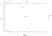
- FIG. 1 shows a schematic structural view of a mobile terminal 100 according to an exemplary embodiment of the present disclosure.
- the mobile terminal 100 includes a body 101 and a flexible display screen 102 provided on the body 101; wherein the flexible display screen 102 is configured to be switched between an expanded state in which the flexible display screen 102 is expanded to a first area and a retracted state in which the flexible display screen 102 is retracted to a second area, and the first area is larger than the second area; a primary antenna 11 is disposed within the body 101, and a spare antenna 12 for replacing the primary antenna 11 is disposed at an edge of the flexible display screen 102.
- the spare antenna is disposed at the edge of the flexible display screen, so that when the state of the flexible display screen is changed, the spare antenna disposed at the edge of the flexible display screen can compensate performance degradation of the primary antenna caused by changes of operating environments, reduce influence of the structural change of the mobile terminal on the antenna transmitting/receiving environment, maintain stability of the antenna performance, and even can improve the antenna performance.
- FIG. 2 is a structural view of a mobile terminal according to another exemplary embodiment of the present disclosure.
- the mobile terminal includes a body 101, a flexible display screen 102 and a flexible display screen receiving component 111.
- the flexible display screen 102 is rectangular.
- the flexible display screen 102 includes four sequentially connected rectangular sides, that is, a first edge 112, a second edge 113, a third edge 114 and a fourth edge 115.
- a rectangular shape may be a rectangular shape or a rounded rectangular shape.
- the first edge 112 of the flexible display screen 102 is fixed to the body 101.
- a primary antenna 116 is provided within the body 101.
- the primary antenna 116 includes at least one of the following antennas: a GPS receiving antenna 103, a Wi-Fi antenna 104, a main antenna 105 and a diversity antenna 106.
- the primary antenna 116 simultaneously including these four kinds of antennas is shown in FIG. 2 as an example.
- a spare antenna 117 for replacing the primary antenna 116 is provided on at least one of the second edge 113, the third edge 114, or the fourth edge 115 of the flexible display screen 102.
- the spare antenna 117 includes at least one of the following antennas: a GPS receiving antenna 107, a Wi-Fi antenna 108, a main antenna 109 and a diversity antenna 110.
- the spare antenna 117 includes one or more of the primary antennas 116.
- the spare antenna 117 simultaneously including these four kinds of antennas in shown in FIG. 2 as an example.
- the expression expanded direction edge means the edge which runs perpendicular to the expanding direction (e.g. the right edge in figure 2 ).
- the non-expanded direction edge is the edge or the edges of the flexible display screen except the expended direction edge (e.g. the other three edges except for the right edge in figure 2 ).
- the flexible display screen is expanded in two different directions (for example towards the right and upwards) there may be two expanded direction edges, i.e. the right edge and the upper edge.
- the non-expanded direction edges are the left edge and the lower edge.
- the third edge 114 of the flexible display screen 102 is secured to the flexible display screen receiving component 111.
- the flexible display screen 102 may be expanded or retracted in the direction of the third edge 114.
- FIG. 2 shows a configuration in which the flexible display screen is in an expanded state
- FIG. 3 shows a configuration in which the flexible display screen is in a retracted state.
- FIG. 4 is a structural view of a mobile terminal according to another exemplary embodiment of the present disclosure.
- the differences of this embodiment compared to the exemplary embodiment shown in FIG. 2 are: a central portion of the second edge 113 and a central portion of the fourth edge 115 of the flexible display screen 102 are fixed to the body 101, respectively.
- the first edge 112 and the second edge 114 may be movable face to face or back to back.
- a spare antenna 117 for replacing the primary antenna 116 is provided on at least one of the first edge 112, the second edge 113, the third edge 114, or the fourth edge 115 of the flexible display screen 102.
- the spare antennas include a first main antenna 303, a first diversity antenna 304, a second main antenna 305, and a second diversity antenna 306.
- the number of the flexible display screen receiving components is two, i.e., a first flexible display screen receiving component 301 and a second flexible display screen receiving component 302.
- the first edge 112 of the flexible display screen 102 is secured to the first flexible display screen receiving component 301.
- the third edge 114 of the flexible display screen 102 is secured to the second flexible display screen receiving component 302.
- the flexible display screen 102 may be expanded or retracted in the direction of the first edge 112 and the third edge 114 (i.e., in the left-right as shown in the figure) simultaneously or separately.
- the manner of receiving the flexible display screen is not limited.
- the flexible display screen is retracted and expanded in at least two manners: a rolling receiving manner and a folding receiving manner. Two receiving manners are respectively described below with reference to the mobile terminal provided by the exemplary embodiment shown in FIG. 2 as an example.
- a reel 401 is provided within the flexible display screen receiving component 111 (and/or the body 101), and its structure is shown in FIG. 5 .
- the reel 401 is composed of a fixing shaft 402 fixed to upper and lower sides of the flexible display screen receiving component 111 and an outer rotating shaft 403 rotatable around the fixing shaft 402.
- the third edge 114 of the flexible display screen 102 is fixed on the outer rotating shaft 403, and the outer rotating shaft 403 rotates to drive the flexible display screen 102 to roll and cover the surface of the outer rotating shaft 403.
- the flexible display screen receiving component 111 may be pushed inwards or pulled outwards by the user.
- the outer rotating shaft 303 When the flexible display screen 102 is pushed inwards, the outer rotating shaft 303 is controlled to rotate backwards, so that the flexible display screen 102 is in a retracted state; and when the flexible display screen 102 is pulled outwards, the outer rotating shaft 403 is controlled to rotate forwards to expand the flexible display screen 102.
- the third edge 114 of the flexible display screen 102 is fixed on the flexible display screen receiving component 111, a flexible display screen receiving groove 501 is provided at a side edge of the body 101, the flexible display screen 102 is equally divided into a plurality of regions by a folding line 502, and after the flexible display screen 102 is sequentially folded along the folding line 502, the flexible display screen 102 may be placed into the flexible display screen receiving groove 501, so that the flexible display screen 102 is retracted.
- the flexible display screen receiving component 111 is pulled to take the flexible display screen 102 out of the flexible display screen receiving groove 501, so that the flexible display screen 102 is expanded.
- control module located inside the body 101 is further included, and the control module may be a CPU or a microprocessor.
- the control module is electrically connected with antennas, respectively.
- switching of working states between the primary antenna 116 and the spare antenna 117 can be realized in at least one of the following three forms:
- FIG. 7 is a structural view of a mobile terminal according to another exemplary embodiment of the present disclosure.
- a control module 601 is added into the body 101 and a driving module 602 is added to the flexible display screen receiving component 111.
- the control module 601 is connected to the driving module 602, the primary antenna 116 and the spare antenna 117, respectively.
- the driving module 602 is an electromechanical component in the form of electric driving.
- control module 601 includes at least one of three functions of: 1. identifying a category of the foreground application; 2. controlling operation and stop of the driving module 602; 3. controlling the primary antenna 116 to be in the working state and controlling the spare antenna 117 to be in the non-working state when the flexible display screen 102 is in the retracted state; and controlling the primary antenna 116 to be in the non-working state and controlling the spare antenna 117 to be in the working state when the flexible display screen 102 is in the expanded state.
- the driving module 602 may drive the flexible display receiving component 111 to rotate forwards to expand the flexible display screen 102 or rotate backwards to receive the flexible display screen 102.
- control module 601 when the control module 601 identifies the category of the foreground application as a game, a video, a reading or other preset program category, the control module 601 sends a first instruction to the driving module 602, and the first instruction is used for controlling the driving module 602 to drive the flexible display screen receiving component 111 to rotate forwards to expand the flexible display screen 102, so that the flexible display screen 102 is in the expanded state.
- the control module 601 sends a second instruction to the primary antenna 116 and the spare antenna 117, and the second instruction is used for controlling the primary antenna 116 and the spare antenna 117 to switch their working states, such that the primary antenna 116 is in the non-working state and the spare antenna 117 is in the working state.
- control module 601 when the control module 601 identifies the category of the foreground application as a game, a video, a reading or other preset program category, the control module 601 sends a third instruction to the driving module 602, and the third instruction is used for controlling the driving module 602 to drive the flexible display screen receiving component 111 to rotate backwards to receive the flexible display screen 102, so that the flexible display screen 102 is in the retracted state.
- the control module 601 sends a fourth instruction to the primary antenna 116 and the spare antenna 117, and the fourth instruction is used for controlling the primary antenna 116 and the spare antenna 117 to switch their working states, such that the primary antenna 116 is in the working state and the spare antenna 117 is in the non-working state.
- the mobile terminal provided by this embodiment can intelligently control the state of the flexible display screen 102 and control the working states of the primary antenna 116 and the spare antenna 117 by identifying the foreground application.
- the mobile terminal can automatically expand or receive the flexible display screen 102, so as to provide good use experience for a user, and meanwhile, the working states of the primary antenna 116 and the spare antenna 117 are automatically switched, so that the mobile terminal always keeps good antenna performance, and the mobile terminal is more convenient to be used.
- FIG. 8 is a structural view of a mobile terminal according to another exemplary embodiment of the present disclosure.
- a control module 601 and a state detection component 703 are added to the exemplary embodiment shown in FIG. 2 .
- the state detection component 703 includes a Hall sensor 701 and a magnet 702.
- control module 601 and the Hall sensor 701 are disposed within the body 101, and a magnet 702 is added to the flexible display screen receiving component 111.
- the control module 601 is connected to the Hall sensor 701, the primary antenna 116, and the spare antenna 117, respectively.
- the control module 601 has two functions: 1. identifying a signal output by the Hall sensor 701; 2. controlling the primary antenna 116 to be in the working state and controlling the spare antenna 117 to be in the non-working state when the flexible display screen 102 is in the retracted state; and controlling the primary antenna 116 to be in the non-working state and controlling the spare antenna 117 to be in the working state when the flexible display screen 102 is in the expanded state.
- the state detection component 703 may detect a state of the flexible display screen 102. Specifically, when the flexible display screen 102 is in the retracted state as shown in FIG. 9 , the magnet 702 is close to the Hall sensor 701, the magnetic field around the Hall sensor 701 is increased, and at this time, the Hall sensor 701 outputs a first signal; when the flexible display screen 102 is in the expanded state as shown in FIG. 8 , the magnet 702 is far away from the Hall sensor 701, the magnetic field around the Hall sensor 701 is weakened, and at this time, the Hall sensor 701 outputs a second signal.
- control module 601 When the control module 601 identifies the first signal output by the Hall sensor 701, the flexible display screen 102 is in the retracted state, the control module 601 sends a fourth instruction to the primary antenna 116 and the spare antenna 117, and controls the primary antenna 116 and the spare antenna 117 to switch their working states such that the primary antenna 116 is in the working state and the spare antenna 117 is in the non-working state.
- control module 601 When the control module 601 identifies that the Hall sensor 701 outputs the second signal, the flexible display screen 102 is in the expanded state, the control module 601 sends a second instruction to the primary antenna 116 and the spare antenna 117, and controls the primary antenna 116 and the spare antenna 117 to switch their working states such that the primary antenna 116 is in the non-working state and the spare antenna 117 is in the working state.
- the mobile terminal provided by this embodiment can automatically control the working states of the primary antenna 116 and the spare antenna 117 by identifying the state of the flexible display screen.
- the antenna is automatically switched into a more suitable working state, so that the user can have good use experience, and also, excellent antenna performances of the mobile terminal can be ensured.
- FIG. 10 is a structural view of a mobile terminal according to another exemplary embodiment of the present disclosure.
- An antenna switch 901 is added to the body based on the exemplary embodiment shown in FIG. 2 .
- the antenna switch 901 is connected to the primary antenna 116 and the spare antenna 117, respectively.
- the antenna switch 901 may control switching of two working states of the primary antenna 116 and the spare antenna 117.
- the primary antenna 116 is controlled to be in the working state and the spare antenna 117 is controlled to be in the non-working state.
- the primary antenna 116 is controlled to be in the non-working state and the spare antenna 117 is controlled to be in the working state.
- the mobile terminal provided by this embodiment can change the working states of the primary antenna 116 and the spare antenna 117 by manually changing the state of the antenna switch 901.
- the antenna switch provides a user with a space to autonomously select an antenna. The user can randomly select one group of antennas from the primary antennas 116 and the spare antennas 117, so that the mobile terminal can adapt to the complex use environments, the antenna performance of the mobile terminal can be ensured, and the user's experience can be improved.
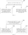
- FIG. 12 is a flowchart of an antenna control method according to an exemplary embodiment of the present disclosure. This embodiment is illustrated as an example that the method is applied to the mobile terminal shown in FIG. 7 .
- the method may include:
- the antenna control method provided by this embodiment provides an antenna automatic control method for automatically switching working states of the primary antenna 116 and the spare antenna 117 according to different states of the flexible display screen 102.
- the antenna may be automatically switched into a more suitable working state when the flexible display screen is expanded or retracted, so that the user can have good use experiences, and also excellent antenna performances of the mobile terminal can be ensured.
- the method for determining the state of the flexible display screen 102 may be identifying the state of the flexible display screen 102 by identifying software instructions, or identifying the state of the flexible display screen 102 by setting hardware.
- the software mode for sensing the state of the flexible display screen 102 may be implemented to identify the state of the flexible display screen 102 by identifying control instructions of the control module 601.
- the hardware mode for sensing the state of the flexible display screen 102 may be implemented to identify the state of the flexible display screen 102 by providing one or more of a state detection component 703, a sensor, and a mechanical component having sensing functions disposed on the mobile terminal.
- FIG. 13 is a flowchart of an antenna control method according to an exemplary embodiment of the present disclosure, which is illustrated as an example that the method is applied to the mobile terminal shown in FIG. 7 .
- the method may include:
- control module 601 sends a third instruction to the driving module 602 to receive the flexible display screen 102, sends a fourth instruction to the primary antenna 116 and the spare antenna 117, and controls the primary antenna 116 and the spare antenna 117 to switch their working states such that the primary antenna 116 is in the working state and the spare antenna 117 is in the non-working state.
- the control method provided by this embodiment provides a method for intelligently controlling a state of the flexible display screen 102 and simultaneously controlling working states of the primary antenna 116 and the spare antenna 117 by identifying a foreground application.
- the mobile terminal automatically expands or receives the flexible display screen 102 when a specific foreground program is used, so that good use experience is provided for the user, and meanwhile, the working states of the primary antenna 116 and the spare antenna 117 are automatically switched, such that the mobile terminal can always keep good antenna performance to be used more conveniently.
- FIG. 14 is a flowchart of an antenna control method according to an exemplary embodiment of the present disclosure.
- the present embodiment is illustrated as an example that the method is applied to the mobile terminal shown in FIG. 8 , and the method may include: step 1401: detecting whether the flexible display screen 102 is in the retracted state or in the expanded state according to the state detection component 703.
- control module 601 identifies the state of the flexible display screen 102 detected by the state detection component 703. If the flexible display screen 102 is in the retracted state, step 1402 is performed; and if the flexible display screen 102 is in the expanded state, step 1403 is performed.
- step 1402 controlling the primary antenna 116 to be in the working state and controlling the spare antenna 117 to be in the non-working state when the flexible display screen 102 is in the retracted state; in one example, the control module 601 sends a fourth instruction to the primary antenna 116 and the spare antenna 117, and controls the primary antenna 116 and the spare antenna 117 to switch their working states such that the primary antenna 116 is in the working state and the spare antenna 117 is in the non-working state.
- step 1403 controlling the primary antenna 116 to be in a non-working state and controlling the spare antenna 117 to be in a working state when the flexible display screen 102 is in the expanded state.
- control module 601 sends a second instruction to the primary antenna 116 and the spare antenna 117, and controls the primary antenna 116 and the spare antenna 117 to switch their working states such that the non-working state of the primary antenna 116 and the working state of the spare antenna 117.
- the antenna control method provided by this embodiment provides a method for controlling the working states of the primary antenna 116 and the spare antenna 117 by identifying whether the flexible display screen 102 is in the retracted or expanded state through the state detection component 703.
- the state detection component 703 is employed to detect the state of the flexible display screen 102, and may transmit the state of the flexible display screen 102 to the control module 601 in real time, so that the sensitivity of the mobile terminal to the state of the flexible display screen 102 can improved, and furthermore the accuracy of controlling of the primary antenna 116 and the spare antenna 117 can be improved, and the excellent antenna performance of the mobile terminal at any time can be ensured.
- the working states of the primary antenna 116 and the spare antenna 117 can be automatically adjusted when the state of the flexible display screen 102 is changed, so that the primary antenna 116 and the spare antenna 117 are always operated in a proper working environment, and the good antenna performance of the mobile terminal can be maintained.
- One embodiment hereinafter is provided to illustrate of the manual control method.
- FIG. 15 is a flowchart of an antenna control method according to an exemplary embodiment of the present disclosure, which is illustrated as an example that the method is applied to the mobile terminal shown in FIG. 10 .
- the method includes: step 1501: determining the state of the antenna switch 901.
- step 1502 is performed; and if the antenna switch 901 is in the second state 1001, step 1503 is performed.
- step 1502 controlling the primary antenna 116 to be in a working state and controlling the spare antenna 117 to be in a non-working state.
- step 1503 controlling the primary antenna 116 to be in the non-working state and controlling the spare antenna 117 to be in the working state.
- the antenna control method provided by this embodiment provides a method for switching the working states of the primary antenna 116 and the spare antenna 117 by controlling the antenna switch 901.
- the antenna switch provides the user with a space to autonomously select an antenna. The user may randomly select one group of antennas from the primary antennas 116 and the spare antennas 117, so that the mobile terminal can adapt to the complex use environment, the antenna performance of the mobile terminal can be ensured, and the use experience of the user can be improved.
- the present disclosure also provides a computer-readable storage medium in which at least one instruction, at least one segment of a program, a code set, or an instruction set is stored, the at least one instruction, the at least one segment of the program, the code set, or the instruction set is loaded and executed by a processor to implement the antenna control method provided in the above embodiments of the method.
Landscapes
- Engineering & Computer Science (AREA)
- Signal Processing (AREA)
- Theoretical Computer Science (AREA)
- Computer Hardware Design (AREA)
- Computer Networks & Wireless Communication (AREA)
- Human Computer Interaction (AREA)
- Physics & Mathematics (AREA)
- General Physics & Mathematics (AREA)
- General Engineering & Computer Science (AREA)
- Telephone Set Structure (AREA)
- Support Of Aerials (AREA)
- Telephone Function (AREA)
Abstract
Description
- This disclosure relates to a field of mobile terminals, and in particular, to a mobile terminal, an antenna control method, and a storage medium.
- Flexible display screens with properties such as arbitrary bending and good flexibility have been adopted by many mobile terminals.
- In a mobile terminal employing a flexible display screen, the flexible display screen may be expanded to enlarge the screen area when the mobile terminal is used, the flexible display screen may be retracted to reduce the screen area when the mobile terminal is carried, and the size of the flexible display screen is selected according to use environments, so as to make the mobile terminal more convenient.
- However, since a structure of the mobile terminal is changed by using the flexible display screen, a new challenge is how to design the antenna of the mobile terminal.
- The embodiments of the present disclosure provide a mobile terminal, an antenna control method and a storage medium, which can solve a problem that the antenna performance is reduced due to the change of a state of a flexible display screen. The technical solution is exemplified as follows.
- According to one aspect of the present disclosure, a mobile terminal is provided, including a body and a flexible display screen disposed on the body;
wherein the flexible display screen is configured to be switched between an expanded state in which the flexible display screen is expanded to form a first area and a retracted state in which the flexible display screen is retracted to form a second area, and the first area is larger than the second area.
a primary antenna is disposed within the body, and a spare antenna for replacing the primary antenna is disposed at an edge of the flexible display screen. - In an optional embodiment, the flexible display screen is rectangular, and a first edge of the flexible display screen is secured to the body; and
the spare antenna is disposed on at least one of a second edge, a third edge or a fourth edge of the flexible display screen. - The rectangle may be a rectangle or a rounded rectangle.
- In an optional embodiment, the flexible display screen is rectangular, a central portion of a second edge of the flexible display screen is secured to the body, and a central portion of a fourth edge of the flexible display screen is secured to the body; the second edge and the fourth edge are two parallel edges; and
the spare antenna is disposed on at least one of the first edge, the second edge, the third edge or the fourth edge of the flexible display screen. - The rectangle may be a rectangle or a rounded rectangle.
- In an optional embodiment, the primary antenna includes at least one of a main antenna, a diversity antenna, a Global Positioning System (GPS) receiving antenna, or a Wireless Fidelity (Wi-Fi) antenna.
- In an optional embodiment, the spare antenna includes one or more primary antennas.
- In an optional embodiment, a control module is further disposed within the body; the control module is respectively connected with the primary antenna and the spare antenna; and
the control module is configured to control the primary antenna to be in a working state and control the spare antenna to be in a non-working state when the flexible display screen is in the retracted state; and control the primary antenna to be in a non-working state and control the spare antenna to be in a working state when the flexible display screen is in the expanded state. - In an optional embodiment, the control module is configured to control the flexible display screen to be in the retracted state or in the expanded state according to a type of a foreground application.
- In an optional embodiment, the body is provided with a state detection component thereon; the control module is connected with the state detection component; and
the control module is configured to determine whether the flexible display screen is in the retracted state or in the expanded state according to a signal output by the state detection component. - In an optional embodiment, the state detection component includes a Hall sensor disposed within the body, and a magnet disposed at a side of the flexible display screen;
the Hall sensor is configured to output a first signal to the control module when the flexible display screen is in the retracted state, and output a second signal to the control module when the flexible display screen is in the expanded state. - In an optional embodiment, an antenna switch is further disposed within the body;
the primary antenna is in a working state and the spare antenna is in a non-working state when the antenna switch is in a first switch state; and
the primary antenna is in a non-working state and the spare antenna is in a working state when the antenna switch is in a second switch state. - According to another aspect of the present disclosure, an antenna control method applied to the mobile terminal as described above is provided. The method includes:
- controlling the primary antenna to be in a working state and controlling the spare antenna to be in a non-working state when the flexible display screen is in the retracted state; and
- controlling the primary antenna to be in a non-working state and controlling the spare antenna to be in a working state when the flexible display screen is in the expanded state.
- In an optional embodiment, the method further includes: controlling the flexible display screen to be in the retracted state or the expanded state according to a type of a foreground application.
- In an optional embodiment, the body is provided with a state detection component thereon; and the method further includes detecting whether the flexible display screen is in the retracted state or in the expanded state according to the state detection component.
- According to another aspect of the present disclosure, an antenna control method applied to a mobile terminal as described above is provided. The method includes:
- controlling the primary antenna to be in a working state and controlling the spare antenna to be in a non-working state when the antenna switch is in a first switch state; and
- controlling the primary antenna to be in a non-working state and controlling the spare antenna to be in a working state when the antenna switch is in a second switch state.
- According to another aspect of the present disclosure, a computer-readable storage medium is provided. The computer program is stored in the computer-readable storage medium, for implementing the antenna control method according to the above aspect when the computer program is executed by a processor.
- The technical solution provided by the embodiments of the present disclosure at least has the following advantages:
- By providing the spare antenna at the edge of flexible display screen, when the flexible display screen state changes, the antenna provided at the edge of the flexible display screen can compensate the performance degradation of the primary antenna caused by changes of operating environments, reduce the influence of the structural change of the mobile terminal on the antenna transmitting/receiving environment, maintain the stability of the antenna performance, and even promote the antenna performance.
- It is preferred that the primary antenna is a set of antennas which is used in the retracted state of the flexible display screen while the spare antenna is a set of antennas used in the expanded state. The spare antenna and the primary antenna may share one or more antennas which are not only used in the retracted state but also in the expanded state. E. g. both the spare antenna and the primary antenna may use (i. e. share) the diversity antenna.
- The accompanying drawings, which are incorporated in and constitute a part of this specification, illustrate embodiments consistent with the present disclosure and, serve to explain some principles of the present disclosure together with the description.
-
FIG. 1 is a schematic structural view of a mobile terminal according to an exemplary embodiment of the present disclosure; -
FIG. 2 is a schematic structural view of a mobile terminal when a flexible display screen is in an expanded state according to another exemplary embodiment of the present disclosure; -
FIG. 3 is a schematic structural view of a mobile terminal when the flexible display screen is in a retracted state according to another exemplary embodiment of the present disclosure; -
FIG. 4 is a schematic structural view of a mobile terminal according to another exemplary embodiment of the present disclosure; -
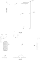
FIG. 5 is a schematic view of a flexible display screen using a rolling receiving structure according to another exemplary embodiment of the present disclosure; -
FIG. 6 is a schematic view of a flexible display screen using a folding receiving structure according to another exemplary embodiment of the present disclosure; -
FIG. 7 is a schematic structural view of a mobile terminal according to another exemplary embodiment of the present disclosure; -
FIG. 8 is a schematic view of a mobile terminal when the flexible display screen is in the expanded state according to another exemplary embodiment of the present disclosure; -
FIG. 9 is a schematic view of a mobile terminal when the flexible display screen is in the retracted state according to another exemplary embodiment of the present disclosure; -
FIG. 10 is a schematic structural view of a mobile terminal when an antenna switch is in a first state according to another exemplary embodiment of the present disclosure; -
FIG. 11 is a schematic structural view of a mobile terminal when the antenna switch is in a second state according to another exemplary embodiment of the present disclosure; -
FIG. 12 is a flowchart of an antenna control method according to an exemplary embodiment of the present disclosure; -
FIG. 13 is a flowchart of an antenna control method according to another exemplary embodiment of the present disclosure; -
FIG. 14 is a flowchart of an antenna control method according to another exemplary embodiment of the present disclosure; and -
FIG. 15 is a flowchart of an antenna control method according to another exemplary embodiment of the present disclosure. - Reference will now be made in detail to the exemplary embodiments, examples of which are illustrated in the accompanying drawings. When the following description are related to the accompanying drawings, the same numbers in different drawings represent the same or similar elements unless otherwise indicated. The implementations described in the following exemplary embodiments do not represent all implementations consistent with the present disclosure. Rather, they are only examples of devices and methods consistent with certain aspects of the present disclosure, as detailed in the appended claims.
-
FIG. 1 shows a schematic structural view of amobile terminal 100 according to an exemplary embodiment of the present disclosure. Themobile terminal 100 includes abody 101 and aflexible display screen 102 provided on thebody 101;
wherein theflexible display screen 102 is configured to be switched between an expanded state in which theflexible display screen 102 is expanded to a first area and a retracted state in which theflexible display screen 102 is retracted to a second area, and the first area is larger than the second area;
aprimary antenna 11 is disposed within thebody 101, and aspare antenna 12 for replacing theprimary antenna 11 is disposed at an edge of theflexible display screen 102. - As described above, in the mobile terminal provided by this embodiment, the spare antenna is disposed at the edge of the flexible display screen, so that when the state of the flexible display screen is changed, the spare antenna disposed at the edge of the flexible display screen can compensate performance degradation of the primary antenna caused by changes of operating environments, reduce influence of the structural change of the mobile terminal on the antenna transmitting/receiving environment, maintain stability of the antenna performance, and even can improve the antenna performance.
-
FIG. 2 is a structural view of a mobile terminal according to another exemplary embodiment of the present disclosure. The mobile terminal includes abody 101, aflexible display screen 102 and a flexible displayscreen receiving component 111. - Illustratively, the
flexible display screen 102 is rectangular. Theflexible display screen 102 includes four sequentially connected rectangular sides, that is, afirst edge 112, asecond edge 113, athird edge 114 and afourth edge 115. - Illustratively, a rectangular shape may be a rectangular shape or a rounded rectangular shape.
- The
first edge 112 of theflexible display screen 102 is fixed to thebody 101. Aprimary antenna 116 is provided within thebody 101. In one example, theprimary antenna 116 includes at least one of the following antennas: aGPS receiving antenna 103, a Wi-Fi antenna 104, amain antenna 105 and adiversity antenna 106. Theprimary antenna 116 simultaneously including these four kinds of antennas is shown inFIG. 2 as an example. - A
spare antenna 117 for replacing theprimary antenna 116 is provided on at least one of thesecond edge 113, thethird edge 114, or thefourth edge 115 of theflexible display screen 102. Thespare antenna 117 includes at least one of the following antennas: aGPS receiving antenna 107, a Wi-Fi antenna 108, a main antenna 109 and a diversity antenna 110. Thespare antenna 117 includes one or more of theprimary antennas 116. Thespare antenna 117 simultaneously including these four kinds of antennas in shown inFIG. 2 as an example. In all embodiments of the present invention, the expression expanded direction edge means the edge which runs perpendicular to the expanding direction (e.g. the right edge infigure 2 ). The non-expanded direction edge is the edge or the edges of the flexible display screen except the expended direction edge (e.g. the other three edges except for the right edge infigure 2 ). However, if the flexible display screen is expanded in two different directions (for example towards the right and upwards) there may be two expanded direction edges, i.e. the right edge and the upper edge. In this example, the non-expanded direction edges are the left edge and the lower edge. - In one example, the
third edge 114 of theflexible display screen 102 is secured to the flexible displayscreen receiving component 111. Theflexible display screen 102 may be expanded or retracted in the direction of thethird edge 114.FIG. 2 shows a configuration in which the flexible display screen is in an expanded state, andFIG. 3 shows a configuration in which the flexible display screen is in a retracted state. -
FIG. 4 is a structural view of a mobile terminal according to another exemplary embodiment of the present disclosure. The differences of this embodiment compared to the exemplary embodiment shown inFIG. 2 are: a central portion of thesecond edge 113 and a central portion of thefourth edge 115 of theflexible display screen 102 are fixed to thebody 101, respectively. Thefirst edge 112 and thesecond edge 114 may be movable face to face or back to back. - A
spare antenna 117 for replacing theprimary antenna 116 is provided on at least one of thefirst edge 112, thesecond edge 113, thethird edge 114, or thefourth edge 115 of theflexible display screen 102.
In one example, the spare antennas include a firstmain antenna 303, afirst diversity antenna 304, a secondmain antenna 305, and asecond diversity antenna 306. Correspondingly, the number of the flexible display screen receiving components is two, i.e., a first flexible displayscreen receiving component 301 and a second flexible displayscreen receiving component 302. Thefirst edge 112 of theflexible display screen 102 is secured to the first flexible display screen receiving component 301.Thethird edge 114 of theflexible display screen 102 is secured to the second flexible displayscreen receiving component 302. Theflexible display screen 102 may be expanded or retracted in the direction of thefirst edge 112 and the third edge 114 (i.e., in the left-right as shown in the figure) simultaneously or separately. - In the embodiment of the present disclosure, the manner of receiving the flexible display screen is not limited. In one exemplary example, the flexible display screen is retracted and expanded in at least two manners: a rolling receiving manner and a folding receiving manner. Two receiving manners are respectively described below with reference to the mobile terminal provided by the exemplary embodiment shown in
FIG. 2 as an example. - For the rolling receiving manner, a
reel 401 is provided within the flexible display screen receiving component 111 (and/or the body 101), and its structure is shown inFIG. 5 . Illustratively, thereel 401 is composed of a fixingshaft 402 fixed to upper and lower sides of the flexible displayscreen receiving component 111 and an outerrotating shaft 403 rotatable around the fixingshaft 402. Thethird edge 114 of theflexible display screen 102 is fixed on the outerrotating shaft 403, and the outerrotating shaft 403 rotates to drive theflexible display screen 102 to roll and cover the surface of the outerrotating shaft 403. The flexible displayscreen receiving component 111 may be pushed inwards or pulled outwards by the user. When theflexible display screen 102 is pushed inwards, the outerrotating shaft 303 is controlled to rotate backwards, so that theflexible display screen 102 is in a retracted state; and when theflexible display screen 102 is pulled outwards, the outerrotating shaft 403 is controlled to rotate forwards to expand theflexible display screen 102. - For the folding receiving manner, as shown in
FIG. 6 , thethird edge 114 of theflexible display screen 102 is fixed on the flexible displayscreen receiving component 111, a flexible displayscreen receiving groove 501 is provided at a side edge of thebody 101, theflexible display screen 102 is equally divided into a plurality of regions by afolding line 502, and after theflexible display screen 102 is sequentially folded along thefolding line 502, theflexible display screen 102 may be placed into the flexible displayscreen receiving groove 501, so that theflexible display screen 102 is retracted. The flexible displayscreen receiving component 111 is pulled to take theflexible display screen 102 out of the flexible displayscreen receiving groove 501, so that theflexible display screen 102 is expanded. - In the above embodiments, generally, the control module located inside the
body 101 is further included, and the control module may be a CPU or a microprocessor. The control module is electrically connected with antennas, respectively. - Based on the above embodiments, switching of working states between the
primary antenna 116 and thespare antenna 117 can be realized in at least one of the following three forms: - a first form: a software control mode;
- a second form: a control mode of combining software and hardware; and
- a third form: a control mode of a hardware switch.
- These three modes will be illustrated in the three different embodiments below.
-
FIG. 7 is a structural view of a mobile terminal according to another exemplary embodiment of the present disclosure. Based on the exemplary embodiment shown inFIG. 2 , acontrol module 601 is added into thebody 101 and adriving module 602 is added to the flexible displayscreen receiving component 111. Thecontrol module 601 is connected to thedriving module 602, theprimary antenna 116 and thespare antenna 117, respectively. Thedriving module 602 is an electromechanical component in the form of electric driving. - In one example, the
control module 601 includes at least one of three functions of: 1. identifying a category of the foreground application; 2. controlling operation and stop of thedriving module 602; 3. controlling theprimary antenna 116 to be in the working state and controlling thespare antenna 117 to be in the non-working state when theflexible display screen 102 is in the retracted state; and controlling theprimary antenna 116 to be in the non-working state and controlling thespare antenna 117 to be in the working state when theflexible display screen 102 is in the expanded state. - The
driving module 602 may drive the flexibledisplay receiving component 111 to rotate forwards to expand theflexible display screen 102 or rotate backwards to receive theflexible display screen 102. - In one example, when the
control module 601 identifies the category of the foreground application as a game, a video, a reading or other preset program category, thecontrol module 601 sends a first instruction to thedriving module 602, and the first instruction is used for controlling thedriving module 602 to drive the flexible displayscreen receiving component 111 to rotate forwards to expand theflexible display screen 102, so that theflexible display screen 102 is in the expanded state. Thecontrol module 601 sends a second instruction to theprimary antenna 116 and thespare antenna 117, and the second instruction is used for controlling theprimary antenna 116 and thespare antenna 117 to switch their working states, such that theprimary antenna 116 is in the non-working state and thespare antenna 117 is in the working state. - In one example, when the
control module 601 identifies the category of the foreground application as a game, a video, a reading or other preset program category, thecontrol module 601 sends a third instruction to thedriving module 602, and the third instruction is used for controlling thedriving module 602 to drive the flexible displayscreen receiving component 111 to rotate backwards to receive theflexible display screen 102, so that theflexible display screen 102 is in the retracted state. Thecontrol module 601 sends a fourth instruction to theprimary antenna 116 and thespare antenna 117, and the fourth instruction is used for controlling theprimary antenna 116 and thespare antenna 117 to switch their working states, such that theprimary antenna 116 is in the working state and thespare antenna 117 is in the non-working state. - As described above, the mobile terminal provided by this embodiment can intelligently control the state of the
flexible display screen 102 and control the working states of theprimary antenna 116 and thespare antenna 117 by identifying the foreground application. When a specific foreground program is used, the mobile terminal can automatically expand or receive theflexible display screen 102, so as to provide good use experience for a user, and meanwhile, the working states of theprimary antenna 116 and thespare antenna 117 are automatically switched, so that the mobile terminal always keeps good antenna performance, and the mobile terminal is more convenient to be used. -
FIG. 8 is a structural view of a mobile terminal according to another exemplary embodiment of the present disclosure. Acontrol module 601 and astate detection component 703 are added to the exemplary embodiment shown inFIG. 2 . Thestate detection component 703 includes aHall sensor 701 and amagnet 702. - Illustratively, the
control module 601 and theHall sensor 701 are disposed within thebody 101, and amagnet 702 is added to the flexible displayscreen receiving component 111. Thecontrol module 601 is connected to theHall sensor 701, theprimary antenna 116, and thespare antenna 117, respectively. - The
control module 601 has two functions: 1. identifying a signal output by theHall sensor 701; 2. controlling theprimary antenna 116 to be in the working state and controlling thespare antenna 117 to be in the non-working state when theflexible display screen 102 is in the retracted state; and controlling theprimary antenna 116 to be in the non-working state and controlling thespare antenna 117 to be in the working state when theflexible display screen 102 is in the expanded state. - The
state detection component 703 may detect a state of theflexible display screen 102. Specifically, when theflexible display screen 102 is in the retracted state as shown inFIG. 9 , themagnet 702 is close to theHall sensor 701, the magnetic field around theHall sensor 701 is increased, and at this time, theHall sensor 701 outputs a first signal; when theflexible display screen 102 is in the expanded state as shown inFIG. 8 , themagnet 702 is far away from theHall sensor 701, the magnetic field around theHall sensor 701 is weakened, and at this time, theHall sensor 701 outputs a second signal. - When the
control module 601 identifies the first signal output by theHall sensor 701, theflexible display screen 102 is in the retracted state, thecontrol module 601 sends a fourth instruction to theprimary antenna 116 and thespare antenna 117, and controls theprimary antenna 116 and thespare antenna 117 to switch their working states such that theprimary antenna 116 is in the working state and thespare antenna 117 is in the non-working state. - When the
control module 601 identifies that theHall sensor 701 outputs the second signal, theflexible display screen 102 is in the expanded state, thecontrol module 601 sends a second instruction to theprimary antenna 116 and thespare antenna 117, and controls theprimary antenna 116 and thespare antenna 117 to switch their working states such that theprimary antenna 116 is in the non-working state and thespare antenna 117 is in the working state. - As described above, the mobile terminal provided by this embodiment can automatically control the working states of the
primary antenna 116 and thespare antenna 117 by identifying the state of the flexible display screen. When the flexible display screen is expanded or retracted, the antenna is automatically switched into a more suitable working state, so that the user can have good use experience, and also, excellent antenna performances of the mobile terminal can be ensured. -
FIG. 10 is a structural view of a mobile terminal according to another exemplary embodiment of the present disclosure. Anantenna switch 901 is added to the body based on the exemplary embodiment shown inFIG. 2 . Theantenna switch 901 is connected to theprimary antenna 116 and thespare antenna 117, respectively. - The
antenna switch 901 may control switching of two working states of theprimary antenna 116 and thespare antenna 117. - As shown in
FIG. 10 , when theantenna switch 901 is in afirst state 902, theprimary antenna 116 is controlled to be in the working state and thespare antenna 117 is controlled to be in the non-working state. - As shown in
FIG. 11 , when theantenna switch 901 is in asecond state 1001, theprimary antenna 116 is controlled to be in the non-working state and thespare antenna 117 is controlled to be in the working state. - As described above, the mobile terminal provided by this embodiment can change the working states of the
primary antenna 116 and thespare antenna 117 by manually changing the state of theantenna switch 901. When the mobile terminal operates in complex use environments, the antenna switch provides a user with a space to autonomously select an antenna. The user can randomly select one group of antennas from theprimary antennas 116 and thespare antennas 117, so that the mobile terminal can adapt to the complex use environments, the antenna performance of the mobile terminal can be ensured, and the user's experience can be improved. -
FIG. 12 is a flowchart of an antenna control method according to an exemplary embodiment of the present disclosure. This embodiment is illustrated as an example that the method is applied to the mobile terminal shown inFIG. 7 . The method may include: - step 1201: determining a state of the
flexible display screen 102; - if the
flexible display screen 102 is in the retracted state,step 1202 is performed; and if theflexible display screen 102 is in the expanded state,step 1203 is performed. - step 1202: controlling the
primary antenna 116 to be in the working state and controlling thespare antenna 117 to be in the non-working state when theflexible display screen 102 is in the retracted state,; - step 1203: controlling the
primary antenna 116 to be in the non-working state and controlling thespare antenna 117 to be in the working state when theflexible display screen 102 is in the expanded state. - As described above, the antenna control method provided by this embodiment provides an antenna automatic control method for automatically switching working states of the
primary antenna 116 and thespare antenna 117 according to different states of theflexible display screen 102. By using the control method, the antenna may be automatically switched into a more suitable working state when the flexible display screen is expanded or retracted, so that the user can have good use experiences, and also excellent antenna performances of the mobile terminal can be ensured. - In the above embodiments of the antenna automatic control method, there may be various methods for determining the state of the
flexible display screen 102. Illustratively, the method for determining the state of theflexible display screen 102 may be identifying the state of theflexible display screen 102 by identifying software instructions, or identifying the state of theflexible display screen 102 by setting hardware. - In one example, the software mode for sensing the state of the
flexible display screen 102 may be implemented to identify the state of theflexible display screen 102 by identifying control instructions of thecontrol module 601. - In one example, the hardware mode for sensing the state of the
flexible display screen 102 may be implemented to identify the state of theflexible display screen 102 by providing one or more of astate detection component 703, a sensor, and a mechanical component having sensing functions disposed on the mobile terminal. - The following two working modes are described in two different embodiments:
- a first embodiment, i.e., an exemplary embodiment of controlling an antenna by using software; and
- a second embodiment, i.e., an exemplary embodiment of controlling the antenna by using a combination of software and hardware.
-
FIG. 13 is a flowchart of an antenna control method according to an exemplary embodiment of the present disclosure, which is illustrated as an example that the method is applied to the mobile terminal shown inFIG. 7 . The method may include: - step 1301: controlling the
flexible display screen 102 to be in the retracted state or in the expanded state according to the type of the foreground application; - the
control module 601 identifies whether the category of the foreground application is a game, a video, a reading or other preset program category, and if yes,step 1302 is performed; if no,step 1303 is performed. - step 1302: controlling the
primary antenna 116 to be in the non-working state and controlling thespare antenna 117 to be in the working state when theflexible display screen 102 is in the expanded state; - in one example, the
control module 601 sends a first instruction to thedriving module 602 to expand theflexible display screen 102, sends a second instruction to theprimary antenna 116 and thespare antenna 117, and controls theprimary antenna 116 and thespare antenna 117 to switch their working states such that theprimary antenna 116 is in the non-working state and thespare antenna 117 is in the working state. - step 1303: controlling the
primary antenna 116 to be in the working state and controlling thespare antenna 117 to be in the non-working state when theflexible display screen 102 is in the retracted state. - In one example, the
control module 601 sends a third instruction to thedriving module 602 to receive theflexible display screen 102, sends a fourth instruction to theprimary antenna 116 and thespare antenna 117, and controls theprimary antenna 116 and thespare antenna 117 to switch their working states such that theprimary antenna 116 is in the working state and thespare antenna 117 is in the non-working state. - As described above, the control method provided by this embodiment provides a method for intelligently controlling a state of the
flexible display screen 102 and simultaneously controlling working states of theprimary antenna 116 and thespare antenna 117 by identifying a foreground application. Combined with the foreground program to control the operation of the antenna, the mobile terminal automatically expands or receives theflexible display screen 102 when a specific foreground program is used, so that good use experience is provided for the user, and meanwhile, the working states of theprimary antenna 116 and thespare antenna 117 are automatically switched, such that the mobile terminal can always keep good antenna performance to be used more conveniently. -
FIG. 14 is a flowchart of an antenna control method according to an exemplary embodiment of the present disclosure. The present embodiment is illustrated as an example that the method is applied to the mobile terminal shown inFIG. 8 , and the method may include:
step 1401: detecting whether theflexible display screen 102 is in the retracted state or in the expanded state according to thestate detection component 703. - In one example, the
control module 601 identifies the state of theflexible display screen 102 detected by thestate detection component 703. If theflexible display screen 102 is in the retracted state,step 1402 is performed; and if theflexible display screen 102 is in the expanded state,step 1403 is performed. - step 1402: controlling the
primary antenna 116 to be in the working state and controlling thespare antenna 117 to be in the non-working state when theflexible display screen 102 is in the retracted state;
in one example, thecontrol module 601 sends a fourth instruction to theprimary antenna 116 and thespare antenna 117, and controls theprimary antenna 116 and thespare antenna 117 to switch their working states such that theprimary antenna 116 is in the working state and thespare antenna 117 is in the non-working state. - step 1403: controlling the
primary antenna 116 to be in a non-working state and controlling thespare antenna 117 to be in a working state when theflexible display screen 102 is in the expanded state. - In one example, the
control module 601 sends a second instruction to theprimary antenna 116 and thespare antenna 117, and controls theprimary antenna 116 and thespare antenna 117 to switch their working states such that the non-working state of theprimary antenna 116 and the working state of thespare antenna 117. - As described above, the antenna control method provided by this embodiment provides a method for controlling the working states of the
primary antenna 116 and thespare antenna 117 by identifying whether theflexible display screen 102 is in the retracted or expanded state through thestate detection component 703. Thestate detection component 703 is employed to detect the state of theflexible display screen 102, and may transmit the state of theflexible display screen 102 to thecontrol module 601 in real time, so that the sensitivity of the mobile terminal to the state of theflexible display screen 102 can improved, and furthermore the accuracy of controlling of theprimary antenna 116 and thespare antenna 117 can be improved, and the excellent antenna performance of the mobile terminal at any time can be ensured. - According to the embodiments of the antenna control method, the working states of the
primary antenna 116 and thespare antenna 117 can be automatically adjusted when the state of theflexible display screen 102 is changed, so that theprimary antenna 116 and thespare antenna 117 are always operated in a proper working environment, and the good antenna performance of the mobile terminal can be maintained. One embodiment hereinafter is provided to illustrate of the manual control method. -
FIG. 15 is a flowchart of an antenna control method according to an exemplary embodiment of the present disclosure, which is illustrated as an example that the method is applied to the mobile terminal shown inFIG. 10 . The method includes:
step 1501: determining the state of theantenna switch 901. - If the
antenna switch 901 is in thefirst state 902,step 1502 is performed; and if theantenna switch 901 is in thesecond state 1001,step 1503 is performed. - step 1502: controlling the
primary antenna 116 to be in a working state and controlling thespare antenna 117 to be in a non-working state. - step 1503: controlling the
primary antenna 116 to be in the non-working state and controlling thespare antenna 117 to be in the working state. - As described above, the antenna control method provided by this embodiment provides a method for switching the working states of the
primary antenna 116 and thespare antenna 117 by controlling theantenna switch 901. When the mobile terminal works in complex use environments, the antenna switch provides the user with a space to autonomously select an antenna. The user may randomly select one group of antennas from theprimary antennas 116 and thespare antennas 117, so that the mobile terminal can adapt to the complex use environment, the antenna performance of the mobile terminal can be ensured, and the use experience of the user can be improved. - The present disclosure also provides a computer-readable storage medium in which at least one instruction, at least one segment of a program, a code set, or an instruction set is stored, the at least one instruction, the at least one segment of the program, the code set, or the instruction set is loaded and executed by a processor to implement the antenna control method provided in the above embodiments of the method.
Claims (16)
- A mobile terminal (100), characterized in that, the mobile terminal comprises a body (101) and a flexible display screen (102) disposed over the body (101);
the flexible display screen (102) being configured to be switchable between an expanded state in which the flexible display screen (102) is expanded to a first area and a retracted state in which the flexible display screen (102) is retracted to a second area, the first area being larger than the second area;
a primary antenna (11, 116) in the body (101), and a spare antenna (12, 117) at an edge of the flexible display screen (102) and configured to replace functions of the primary antenna (11, 116). - The mobile terminal (100) according to claim 1, characterized in that, the flexible display screen (102) is rectangular, and a first edge (112) of the flexible display screen (102) is secured to the body (101); and
the spare antenna (117) is disposed on at least one of a second edge (113), a third edge (114) or a fourth edge (115) of the flexible display screen (102). - The mobile terminal (100) according to claim 1, characterized in that, the flexible display screen (102) is rectangular, a central portion of a second edge (113) of the flexible display screen (102) is secured to the body (101), and a central portion of a fourth edge (115) of the flexible display screen (102) is secured to the body (101); wherein the second edge (113) and the fourth edge (115) are two parallel edges; and
the spare antenna (117) is disposed on at least one of a first edge (112), the second edge (113), a third edge (114) or the fourth edge (115) of the flexible display screen (102). - The mobile terminal (100) according to claim 1, characterized in that, the primary antenna (116) is disposed at a non-expanded direction edge of the flexible display screen (102) that is in the retracted state,
the flexible display screen (102) is switched between the expanded state and the retracted state via an expanded direction edge, an edge other than the expanded direction edge of the flexible display screen (102) that is in the retracted state is the non-expanded direction edge. - The mobile terminal (100) according to claim 1, characterized in that, the spare antenna (117) is disposed at an edge of the flexible display screen (102) that is in the expanded state.
- The mobile terminal (100) according to claim 1, characterized in that, the primary antenna (11, 116) comprises at least one of a main antenna (109), a diversity antenna (110), a Global Positioning System (GPS) receiving antenna (107), or a wireless fidelity (Wi-Fi) antenna (108);
the spare antenna (117) comprises at least one of a main antenna (109), a diversity antenna (110), a Global Positioning System (GPS) receiving antenna (107), or a wireless fidelity (Wi-Fi) antenna (108). - The mobile terminal (100) according to claim 6, characterized in that, the spare antenna (12, 117) reuses one or more of primary antennas (11, 116).
- The mobile terminal (100) according to any one of claims 1-7, characterized in that, a control module (601) is further disposed within the body (101); wherein the control module (601) is respectively connected with the primary antenna (116) and the spare antenna (117); and
the control module (601) is configured to control the primary antenna (116) to be in a working state and control the spare antenna (117) to be in a non-working state when the flexible display screen (102) is in the retracted state; and the control module (601) is configured to control the primary antenna (116) to be in a non-working state and control the spare antenna (117) to be in a working state when the flexible display screen (102) is in the expanded state. - The mobile terminal (100) according to claim 8, characterized in that, the control module (601) is configured to control the flexible display screen (102) to be in the retracted state or in the expanded state according to a type of a foreground application.
- The mobile terminal (100) according to claim 8, characterized in that, the body (101) is provided with a state detection component (703); the control module (601) is connected with the state detection component (703); and
the control module (601) is configured to determine whether the flexible display screen (102) is in the retracted state or in the expanded state according to a signal output by the state detection component (703). - The mobile terminal (100) according to claim 10, characterized in that, the state detection component (703) comprises a Hall sensor (701) disposed within the body (101), and a magnet (702) disposed at a side of the flexible display screen (102);
the Hall sensor (701) is configured to output a first signal to the control module (601) when the flexible display screen (102) is in the retracted state, and output a second signal to the control module (601) when the flexible display screen (102) is in the expanded state. - The mobile terminal (100) according to any one of claims 1-7, characterized in that, an antenna switch (901) is further disposed within the body (101);
the primary antenna (116) is in a working state and the spare antenna (117) is in a non-working state when the antenna switch (901) is in a first switch state; and
the primary antenna (116) is in a non-working state and the spare antenna (117) is in a working state when the antenna switch (901) is in a second switch state. - An antenna control method, characterized in that, the antenna control method is applied into a mobile terminal (100) according to any one of claims 1 to 11, and the method comprises: controlling the primary antenna (116) to be in a working state and controlling the spare antenna (117) to be in a non-working state when the flexible display screen (102) is in the retracted state; and
controlling the primary antenna (116) to be in a non-working state and controlling the spare antenna (117) to be in a working state when the flexible display screen (102) is in the expanded state. - The method according to claim 13, characterized in that, the method further comprises:
controlling the flexible display screen (102) to be in the retracted state or in the expanded state according to a type of a foreground application. - The method according to claim 13, characterized in that, the body (101) is provided with a state detection component (703); and the method further comprises:
detecting whether the flexible display screen (102) is in the retracted state or in the expanded state according to the state detection component (703). - An antenna control method, characterized in that, the antenna control method is applied to a mobile terminal (100) according to claim 12, and comprises:controlling the primary antenna (116) to be in a working state and controlling the spare antenna (117) to be in a non-working state when the antenna switch (901) is in a first switch state; andcontrolling the primary antenna (116) to be in a non-working state and controlling the spare antenna (117) to be in a working state when the antenna switch (901) is in a second switch state.
Applications Claiming Priority (1)
| Application Number | Priority Date | Filing Date | Title |
|---|---|---|---|
| CN201910646231.2A CN112243051B (en) | 2019-07-17 | 2019-07-17 | Mobile terminal, antenna control method and storage medium |
Publications (2)
| Publication Number | Publication Date |
|---|---|
| EP3767428A1 true EP3767428A1 (en) | 2021-01-20 |
| EP3767428B1 EP3767428B1 (en) | 2026-01-28 |
Family
ID=69844697
Family Applications (1)
| Application Number | Title | Priority Date | Filing Date |
|---|---|---|---|
| EP20163355.9A Active EP3767428B1 (en) | 2019-07-17 | 2020-03-16 | Mobile terminal and antenna control method |
Country Status (7)
| Country | Link |
|---|---|
| US (1) | US11315445B2 (en) |
| EP (1) | EP3767428B1 (en) |
| JP (1) | JP7170667B2 (en) |
| KR (1) | KR102229913B1 (en) |
| CN (1) | CN112243051B (en) |
| RU (1) | RU2729061C1 (en) |
| WO (1) | WO2021007967A1 (en) |
Cited By (1)
| Publication number | Priority date | Publication date | Assignee | Title |
|---|---|---|---|---|
| EP4207486A4 (en) * | 2020-09-22 | 2024-02-28 | Guangdong Oppo Mobile Telecommunications Corp., Ltd. | Electronic device and electronic device control method |
Families Citing this family (8)
| Publication number | Priority date | Publication date | Assignee | Title |
|---|---|---|---|---|
| KR20220052047A (en) | 2020-10-20 | 2022-04-27 | 삼성전자주식회사 | Method and electronic device for measuring location based on antenna |
| EP4224633A4 (en) | 2020-11-13 | 2024-03-27 | Samsung Electronics Co., Ltd. | ELECTRONIC DEVICE INCLUDING AN ANTENNA |
| CN113193388B (en) * | 2021-04-15 | 2023-06-16 | 维沃移动通信有限公司 | Electronic equipment |
| KR102845136B1 (en) | 2021-04-22 | 2025-08-12 | 삼성전자주식회사 | Antenna structure for improving radiation performance and electronic device including same |
| CN113193344B (en) * | 2021-04-28 | 2022-11-25 | 安徽华米健康医疗有限公司 | Electronic device and antenna control method thereof |
| CN113381166B (en) * | 2021-06-10 | 2025-07-15 | 清华大学 | Flexible transparent in-screen antenna for communication and millimeter wave radar sensing and its setting method |
| KR20230040800A (en) * | 2021-09-16 | 2023-03-23 | 삼성전자주식회사 | Electronic device including flexible display and method for controlling the same |
| EP4332722A4 (en) | 2021-09-16 | 2024-09-11 | Samsung Electronics Co., Ltd. | ELECTRONIC DEVICE WITH FLEXIBLE DISPLAY AND CONTROL METHOD THEREFOR |
Citations (8)
| Publication number | Priority date | Publication date | Assignee | Title |
|---|---|---|---|---|
| US20060118625A1 (en) * | 2004-12-03 | 2006-06-08 | Nec Corporation | Radio terminal |
| US20170103735A1 (en) * | 2015-10-13 | 2017-04-13 | Lg Electronics Inc. | Display Device |
| US9964995B1 (en) * | 2017-06-21 | 2018-05-08 | Dell Products L.P. | Dynamic antenna orientation with a flexible information handling system display |
| CN108594934A (en) * | 2018-03-12 | 2018-09-28 | 维沃移动通信有限公司 | A kind of terminal device and its control method |
| CN108810204A (en) * | 2018-06-14 | 2018-11-13 | 珠海市魅族科技有限公司 | Flexible electronic devices |
| US20180358684A1 (en) * | 2013-02-25 | 2018-12-13 | Samsung Electronics Co., Ltd. | Portable terminal with antenna device for display element or display assembly including flexible functional region |
| CN109167153A (en) * | 2018-08-29 | 2019-01-08 | Oppo广东移动通信有限公司 | Electronic equipment, aerial radiation body controlling means and storage medium |
| CN109725680A (en) * | 2018-12-25 | 2019-05-07 | 维沃移动通信有限公司 | A kind of mobile terminal and method of controlling antenna |
Family Cites Families (30)
| Publication number | Priority date | Publication date | Assignee | Title |
|---|---|---|---|---|
| US7050835B2 (en) | 2001-12-12 | 2006-05-23 | Universal Display Corporation | Intelligent multi-media display communication system |
| KR100641140B1 (en) * | 2004-03-17 | 2006-11-02 | 엘지전자 주식회사 | Diversity antenna installation structure of portable terminal |
| JP4321588B2 (en) * | 2004-11-08 | 2009-08-26 | パナソニック株式会社 | Portable radio |
| US7558057B1 (en) * | 2005-06-06 | 2009-07-07 | Alex Naksen | Personal digital device with adjustable interface |
| JP2008072382A (en) * | 2006-09-13 | 2008-03-27 | Toshiba Corp | ANTENNA DEVICE AND RADIO DEVICE |
| KR100818170B1 (en) * | 2007-03-13 | 2008-04-02 | 한국과학기술원 | Scroll type flexible display device and personal digital assistant with same |
| US8711566B2 (en) * | 2011-09-02 | 2014-04-29 | Microsoft Corporation | Expandable mobile device |
| GB201218004D0 (en) * | 2012-10-08 | 2012-11-21 | Plastic Logic Ltd | Foldable electronic display |
| CN103873670B (en) * | 2012-12-17 | 2017-04-19 | 联想(北京)有限公司 | Method and electronic equipment for controlling flexible screen shape |
| TWI582640B (en) * | 2013-01-10 | 2017-05-11 | 黃海濤 | Hand-held electronic device having rolled-up screen and display method thereof |
| KR102022322B1 (en) | 2013-10-01 | 2019-09-18 | 엘지디스플레이 주식회사 | Flexible device and method for detecting bending of the same |
| KR101727971B1 (en) * | 2014-02-21 | 2017-04-18 | 삼성전자주식회사 | Foldable device |
| CN104539764B (en) * | 2014-12-23 | 2018-02-16 | 上海摩软通讯技术有限公司 | Can be according to the mobile terminal of the automatic deformation of use state and its method for realizing deformation |
| KR102359550B1 (en) * | 2015-08-26 | 2022-02-08 | 엘지전자 주식회사 | Flexible display device and operating method thereof |
| KR102543912B1 (en) * | 2015-10-05 | 2023-06-15 | 삼성전자 주식회사 | Electronic device comprising multiple display, and method for controlling the same |
| JP7054386B2 (en) * | 2015-10-21 | 2022-04-13 | アロヴィア,インコーポレイテッド | Improved voluntary pop-up display device |
| KR20170048007A (en) * | 2015-10-26 | 2017-05-08 | 엘지전자 주식회사 | Flexible display device and operating method thereof |
| KR20170050270A (en) * | 2015-10-30 | 2017-05-11 | 엘지전자 주식회사 | Rollable mobile device and method for controlling the same |
| KR102434865B1 (en) * | 2015-11-27 | 2022-08-22 | 엘지전자 주식회사 | Rollable mobile terminal and control method thereof |
| US10516201B2 (en) * | 2016-04-11 | 2019-12-24 | Samsung Electronics Co., Ltd. | Wireless communication system including polarization-agile phased-array antenna |
| KR102470945B1 (en) * | 2016-06-15 | 2022-11-25 | 엘지전자 주식회사 | Mobile terminal |
| KR102666192B1 (en) * | 2016-07-28 | 2024-05-14 | 삼성디스플레이 주식회사 | Display device |
| KR102426694B1 (en) * | 2017-05-02 | 2022-07-29 | 삼성전자주식회사 | electronic device including flexible display |
| US11158929B2 (en) * | 2017-09-29 | 2021-10-26 | Futurewei Technologies, Inc. | Antenna placement arrangements on device with extendable display |
| CN108024444B (en) * | 2017-11-30 | 2020-03-20 | 珠海市魅族科技有限公司 | Flexible electronic device |
| CN108039569B (en) * | 2017-11-30 | 2020-02-21 | 珠海市魅族科技有限公司 | Flexible electronic device |
| CN108347759B (en) * | 2018-02-07 | 2020-06-30 | 维沃移动通信有限公司 | Anti-interference method for flexible screen and mobile terminal |
| KR102266152B1 (en) * | 2018-02-22 | 2021-06-17 | 삼성전자주식회사 | Electronic device including flexible display and method for controlling thereof |
| CN109167151B (en) * | 2018-08-29 | 2021-02-09 | Oppo广东移动通信有限公司 | Electronic equipment |
| EP3618184B1 (en) * | 2018-08-29 | 2025-12-24 | Guangdong Oppo Mobile Telecommunications Corp., Ltd. | Electronic device with antenna mechanism |
-
2019
- 2019-07-17 CN CN201910646231.2A patent/CN112243051B/en active Active
- 2019-10-15 KR KR1020197033651A patent/KR102229913B1/en active Active
- 2019-10-15 RU RU2019139068A patent/RU2729061C1/en active
- 2019-10-15 JP JP2019562613A patent/JP7170667B2/en active Active
- 2019-10-15 WO PCT/CN2019/111318 patent/WO2021007967A1/en not_active Ceased
- 2019-11-20 US US16/690,094 patent/US11315445B2/en active Active
-
2020
- 2020-03-16 EP EP20163355.9A patent/EP3767428B1/en active Active
Patent Citations (8)
| Publication number | Priority date | Publication date | Assignee | Title |
|---|---|---|---|---|
| US20060118625A1 (en) * | 2004-12-03 | 2006-06-08 | Nec Corporation | Radio terminal |
| US20180358684A1 (en) * | 2013-02-25 | 2018-12-13 | Samsung Electronics Co., Ltd. | Portable terminal with antenna device for display element or display assembly including flexible functional region |
| US20170103735A1 (en) * | 2015-10-13 | 2017-04-13 | Lg Electronics Inc. | Display Device |
| US9964995B1 (en) * | 2017-06-21 | 2018-05-08 | Dell Products L.P. | Dynamic antenna orientation with a flexible information handling system display |
| CN108594934A (en) * | 2018-03-12 | 2018-09-28 | 维沃移动通信有限公司 | A kind of terminal device and its control method |
| CN108810204A (en) * | 2018-06-14 | 2018-11-13 | 珠海市魅族科技有限公司 | Flexible electronic devices |
| CN109167153A (en) * | 2018-08-29 | 2019-01-08 | Oppo广东移动通信有限公司 | Electronic equipment, aerial radiation body controlling means and storage medium |
| CN109725680A (en) * | 2018-12-25 | 2019-05-07 | 维沃移动通信有限公司 | A kind of mobile terminal and method of controlling antenna |
Cited By (1)
| Publication number | Priority date | Publication date | Assignee | Title |
|---|---|---|---|---|
| EP4207486A4 (en) * | 2020-09-22 | 2024-02-28 | Guangdong Oppo Mobile Telecommunications Corp., Ltd. | Electronic device and electronic device control method |
Also Published As
| Publication number | Publication date |
|---|---|
| EP3767428B1 (en) | 2026-01-28 |
| US11315445B2 (en) | 2022-04-26 |
| WO2021007967A1 (en) | 2021-01-21 |
| RU2729061C1 (en) | 2020-08-04 |
| JP7170667B2 (en) | 2022-11-14 |
| CN112243051B (en) | 2021-10-22 |
| US20210020076A1 (en) | 2021-01-21 |
| JP2021533583A (en) | 2021-12-02 |
| CN112243051A (en) | 2021-01-19 |
| KR102229913B1 (en) | 2021-03-19 |
| KR20210010294A (en) | 2021-01-27 |
Similar Documents
| Publication | Publication Date | Title |
|---|---|---|
| EP3767428B1 (en) | Mobile terminal and antenna control method | |
| KR102246605B1 (en) | Mobile terminal, antenna control method, program and recording medium | |
| EP3942786B1 (en) | Mobile terminal | |
| JP2021524165A (en) | Screen expansion / storage unit and terminal | |
| EP3065309B1 (en) | Electronic device and method for performing communication by selectively using multiple antennas | |
| KR20180056068A (en) | Electronic device and method for controlling unmanned aerial vehicle | |
| US20210105051A1 (en) | Electronic device for performing beamforming in wireless communication system and method therefor | |
| CN104617974B (en) | Electronic equipment | |
| CN110138969A (en) | The display methods of collapsible terminal and its starting logo | |
| US20240209983A1 (en) | Handheld gimbal, handheld gimbal control method and apparatus, and storage medium | |
| JP6605112B2 (en) | Steering device and operation reception method | |
| KR20210151674A (en) | Electronic device having rollable display and display method thereof | |
| KR20220078437A (en) | Application execution processor and elecronic device including same | |
| JP6435310B2 (en) | Control device, program, and communication method | |
| US20240064551A1 (en) | Mobile communication system and usage scenario determination method for the same | |
| JP6335540B2 (en) | Mobile terminal device | |
| JP6647377B2 (en) | Communication device, information processing method, program, and flight system | |
| JP5519952B2 (en) | COMMUNICATION DEVICE AND ITS CONTROL METHOD | |
| JP2020188339A (en) | Communication device, power supply start method, and program | |
| JP2010109663A (en) | Wireless terminal and radio control method | |
| EP3851951A1 (en) | Display device, display device control method, and display system | |
| KR20250047551A (en) | Electronic device including antenna | |
| CN121359435A (en) | Electronic devices and methods for providing antenna-related user interfaces | |
| CN120814145A (en) | Wireless charging method and electronic device supporting same |
Legal Events
| Date | Code | Title | Description |
|---|---|---|---|
| PUAI | Public reference made under article 153(3) epc to a published international application that has entered the european phase |
Free format text: ORIGINAL CODE: 0009012 |
|
| STAA | Information on the status of an ep patent application or granted ep patent |
Free format text: STATUS: THE APPLICATION HAS BEEN PUBLISHED |
|
| AK | Designated contracting states |
Kind code of ref document: A1 Designated state(s): AL AT BE BG CH CY CZ DE DK EE ES FI FR GB GR HR HU IE IS IT LI LT LU LV MC MK MT NL NO PL PT RO RS SE SI SK SM TR |
|
| AX | Request for extension of the european patent |
Extension state: BA ME |
|
| STAA | Information on the status of an ep patent application or granted ep patent |
Free format text: STATUS: REQUEST FOR EXAMINATION WAS MADE |
|
| 17P | Request for examination filed |
Effective date: 20210720 |
|
| RBV | Designated contracting states (corrected) |
Designated state(s): AL AT BE BG CH CY CZ DE DK EE ES FI FR GB GR HR HU IE IS IT LI LT LU LV MC MK MT NL NO PL PT RO RS SE SI SK SM TR |
|
| STAA | Information on the status of an ep patent application or granted ep patent |
Free format text: STATUS: EXAMINATION IS IN PROGRESS |
|
| 17Q | First examination report despatched |
Effective date: 20230103 |
|
| GRAP | Despatch of communication of intention to grant a patent |
Free format text: ORIGINAL CODE: EPIDOSNIGR1 |
|
| STAA | Information on the status of an ep patent application or granted ep patent |
Free format text: STATUS: GRANT OF PATENT IS INTENDED |
|
| INTG | Intention to grant announced |
Effective date: 20251001 |
|
| GRAS | Grant fee paid |
Free format text: ORIGINAL CODE: EPIDOSNIGR3 |
|
| GRAA | (expected) grant |
Free format text: ORIGINAL CODE: 0009210 |
|
| STAA | Information on the status of an ep patent application or granted ep patent |
Free format text: STATUS: THE PATENT HAS BEEN GRANTED |
|
| AK | Designated contracting states |
Kind code of ref document: B1 Designated state(s): AL AT BE BG CH CY CZ DE DK EE ES FI FR GB GR HR HU IE IS IT LI LT LU LV MC MK MT NL NO PL PT RO RS SE SI SK SM TR |
|
| REG | Reference to a national code |
Ref country code: CH Ref legal event code: F10 Free format text: ST27 STATUS EVENT CODE: U-0-0-F10-F00 (AS PROVIDED BY THE NATIONAL OFFICE) Effective date: 20260128 Ref country code: GB Ref legal event code: FG4D |
|
| REG | Reference to a national code |
Ref country code: DE Ref legal event code: R096 Ref document number: 602020065756 Country of ref document: DE |
|
| REG | Reference to a national code |
Ref country code: IE Ref legal event code: FG4D |
|
| PGFP | Annual fee paid to national office [announced via postgrant information from national office to epo] |
Ref country code: GB Payment date: 20260216 Year of fee payment: 7 |