EP3767423A1 - Work machine and work machine support server - Google Patents
Work machine and work machine support server Download PDFInfo
- Publication number
- EP3767423A1 EP3767423A1 EP20184780.3A EP20184780A EP3767423A1 EP 3767423 A1 EP3767423 A1 EP 3767423A1 EP 20184780 A EP20184780 A EP 20184780A EP 3767423 A1 EP3767423 A1 EP 3767423A1
- Authority
- EP
- European Patent Office
- Prior art keywords
- unmanned aircraft
- working mechanism
- contact
- work machine
- possibility
- Prior art date
- Legal status (The legal status is an assumption and is not a legal conclusion. Google has not performed a legal analysis and makes no representation as to the accuracy of the status listed.)
- Granted
Links
Images



Classifications
-
- G—PHYSICS
- G05—CONTROLLING; REGULATING
- G05D—SYSTEMS FOR CONTROLLING OR REGULATING NON-ELECTRIC VARIABLES
- G05D1/00—Control of position, course, altitude or attitude of land, water, air or space vehicles, e.g. using automatic pilots
- G05D1/10—Simultaneous control of position or course in three dimensions
- G05D1/101—Simultaneous control of position or course in three dimensions specially adapted for aircraft
- G05D1/106—Change initiated in response to external conditions, e.g. avoidance of elevated terrain or of no-fly zones
-
- G—PHYSICS
- G05—CONTROLLING; REGULATING
- G05D—SYSTEMS FOR CONTROLLING OR REGULATING NON-ELECTRIC VARIABLES
- G05D1/00—Control of position, course, altitude or attitude of land, water, air or space vehicles, e.g. using automatic pilots
- G05D1/0094—Control of position, course, altitude or attitude of land, water, air or space vehicles, e.g. using automatic pilots involving pointing a payload, e.g. camera, weapon, sensor, towards a fixed or moving target
-
- E—FIXED CONSTRUCTIONS
- E02—HYDRAULIC ENGINEERING; FOUNDATIONS; SOIL SHIFTING
- E02F—DREDGING; SOIL-SHIFTING
- E02F9/00—Component parts of dredgers or soil-shifting machines, not restricted to one of the kinds covered by groups E02F3/00 - E02F7/00
- E02F9/20—Drives; Control devices
- E02F9/2025—Particular purposes of control systems not otherwise provided for
- E02F9/205—Remotely operated machines, e.g. unmanned vehicles
-
- E—FIXED CONSTRUCTIONS
- E02—HYDRAULIC ENGINEERING; FOUNDATIONS; SOIL SHIFTING
- E02F—DREDGING; SOIL-SHIFTING
- E02F9/00—Component parts of dredgers or soil-shifting machines, not restricted to one of the kinds covered by groups E02F3/00 - E02F7/00
- E02F9/26—Indicating devices
- E02F9/261—Surveying the work-site to be treated
- E02F9/262—Surveying the work-site to be treated with follow-up actions to control the work tool, e.g. controller
-
- B—PERFORMING OPERATIONS; TRANSPORTING
- B64—AIRCRAFT; AVIATION; COSMONAUTICS
- B64U—UNMANNED AERIAL VEHICLES [UAV]; EQUIPMENT THEREFOR
- B64U10/00—Type of UAV
- B64U10/10—Rotorcrafts
- B64U10/13—Flying platforms
-
- B—PERFORMING OPERATIONS; TRANSPORTING
- B64—AIRCRAFT; AVIATION; COSMONAUTICS
- B64U—UNMANNED AERIAL VEHICLES [UAV]; EQUIPMENT THEREFOR
- B64U2101/00—UAVs specially adapted for particular uses or applications
- B64U2101/30—UAVs specially adapted for particular uses or applications for imaging, photography or videography
-
- B—PERFORMING OPERATIONS; TRANSPORTING
- B64—AIRCRAFT; AVIATION; COSMONAUTICS
- B64U—UNMANNED AERIAL VEHICLES [UAV]; EQUIPMENT THEREFOR
- B64U2201/00—UAVs characterised by their flight controls
- B64U2201/10—UAVs characterised by their flight controls autonomous, i.e. by navigating independently from ground or air stations, e.g. by using inertial navigation systems [INS]
-
- B—PERFORMING OPERATIONS; TRANSPORTING
- B64—AIRCRAFT; AVIATION; COSMONAUTICS
- B64U—UNMANNED AERIAL VEHICLES [UAV]; EQUIPMENT THEREFOR
- B64U2201/00—UAVs characterised by their flight controls
- B64U2201/20—Remote controls
-
- B—PERFORMING OPERATIONS; TRANSPORTING
- B64—AIRCRAFT; AVIATION; COSMONAUTICS
- B64U—UNMANNED AERIAL VEHICLES [UAV]; EQUIPMENT THEREFOR
- B64U70/00—Launching, take-off or landing arrangements
- B64U70/90—Launching from or landing on platforms
Definitions
- the present invention relates to a work machine such as a building demolition machine.
- An object of the present invention is, therefore, to provide mainly a work machine that can reduce the possibility of contact with an unmanned aircraft flying around.
- the present invention relates to a work machine including: a lower traveling body; an upper pivoting body that can pivot with respect to the lower traveling body; a working mechanism that extends from the upper pivoting body; and a control unit that controls the operation mode of each of the lower traveling body, the upper pivoting body, and the working mechanism. Further, the present invention relates to a work machine support server that has a function to communicate with each of the work machine and an unmanned aircraft.
- control unit includes: a contact possibility recognition element that recognizes a degree of possibility of contact between the working mechanism and the unmanned aircraft according to a relative position of the unmanned aircraft with reference to the working mechanism; and a contact avoidance operation control element which, if the contact possibility recognition element recognizes that a contact possibility is high, transmits a specified signal for changing a flight mode of the unmanned aircraft to the unmanned aircraft or a remote control unit of the unmanned aircraft.
- a work machine support server in accordance with the present invention includes: a contact possibility recognition element which recognizes a degree of possibility of contact between the working mechanism and the unmanned aircraft based on a relative position of the unmanned aircraft with reference to the working mechanism according to communication with at least one of the work machine and the unmanned aircraft; and a contact avoidance operation control element which, if the contact possibility recognition element recognizes that the contact possibility is high, transmits a specified signal for changing a flight mode of the unmanned aircraft to the unmanned aircraft or a remote control unit of the unmanned aircraft.
- a work machine 10 as one embodiment of the present invention illustrated in FIG. 1 performs predetermined work in collaboration with an unmanned aircraft 40.
- the work machine 10 is, for example, a crawler excavator (construction machine), and includes a crawler type lower traveling body 110 and an upper pivoting body 120 pivotably mounted on the lower traveling body 110 through the intermediary of a pivoting mechanism 130.
- a cab (driver compartment) 122 is provided on the left front side of the upper pivoting body 120.
- a work attachment serving as a working mechanism 140 is provided at the front center of the upper pivoting body 120.
- the working mechanism 140 includes a boom 141 liftably attached to the upper pivoting body 120, an arm 143 rotatably connected to the distal end of the boom 141, and a bucket 145 rotatably connected to the distal end of the arm 143.
- Attached to the working mechanism 140 are a boom cylinder 142, an arm cylinder 144, and a bucket cylinder 146 composed of expandable hydraulic cylinders.
- other attachment such as a nibbler may be attached to the distal end of the arm 143.
- the boom cylinder 142 is interposed between the boom 141 and the upper pivoting body 120 so that the boom cylinder 142 expands or contracts by receiving the supply of hydraulic oil thereby to cause the boom 141 to pivot in an upward or downward direction.
- the arm cylinder 144 is interposed between the arm 143 and the boom 141 such that the arm cylinder 144 expands or contracts by receiving the supply of hydraulic oil thereby to cause the arm 143 to pivot around a horizontal axis with respect to the boom 141.
- the bucket cylinder 146 is interposed between the bucket 145 and the arm 143 such that the bucket cylinder 146 expands or contracts by receiving the supply of hydraulic oil thereby to cause the bucket 145 to pivot around the horizontal axis with respect to the arm 143.
- the work machine 10 includes a work machine control unit 20, a wireless communication unit 202, an input interface 210, and an output interface 220.
- the work machine control unit 20 is composed of an arithmetic processing unit (a single-core processor, a multi-core processor, or a processor core that constitutes the single-core processor or the multi-core processor), which reads necessary data and software from a memory or other storage device, and executes arithmetic processing on the data according to the software.
- arithmetic processing unit a single-core processor, a multi-core processor, or a processor core that constitutes the single-core processor or the multi-core processor
- the work machine control unit 20 includes a contact possibility recognition element 21 and a contact avoidance operation control element 22.
- the contact possibility recognition element 21 recognizes the degree of possibility of contact between the working mechanism 140 and the unmanned aircraft 40 on the basis of the relative position of the unmanned aircraft 40 with reference to the working mechanism 140.
- the term "recognition” refers to a concept that encompasses determining, designating or estimating the degree of possibility of contact on the basis of the relative position of the unmanned aircraft 40 with reference to the working mechanism 140, and receiving a result of the determination or reading from a storage unit. If the contact possibility recognition element 21 recognizes that the contact possibility is high, then the contact avoidance operation control element 22 transmits a specified signal for changing the flight mode of the unmanned aircraft 40 to the unmanned aircraft 40 or a remote control unit 50.
- An operating mechanism 211 constituting the input interface 210 includes a travel operating unit, a pivoting operating unit, a boom operating unit, an arm operating unit, and a bucket operating unit.
- Each of the operating units has an operating lever subjected to rotational operations.
- the operating lever (travel lever) of the travel operating unit is operated to move the lower traveling body 110.
- the travel lever may also serve as a travel pedal.
- a travel pedal fixed to the base or lower end of the travel lever may be provided.
- the operating lever of the pivoting operating unit (pivoting lever) is operated to move a hydraulic pivoting motor constituting the pivoting mechanism 130.
- the operating lever of the boom operating unit (boom lever) is operated to move a boom cylinder 142.
- the operating lever of the arm operating unit (arm lever) is operated to move an arm cylinder 144.
- An operating lever (bucket lever) of the bucket operating unit is operated to move a bucket cylinder 146.
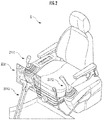
- the operating levers constituting the operating mechanism 211 are placed, for example, around a seat S for an operator to sit on, as illustrated in FIG. 2 .
- the seat S is in the form of a high-back chair with armrests, but may be in any form that allows an operator to sit thereon, such as a low-back chair without a headrest, or a chair without a backrest.
- a pair of left and right travel levers 2110 corresponding to the left and right crawlers are placed side by side in front of the seat S.
- a single operating lever may serve as a plurality of operating levers.
- a right operating lever 2111 provided in front of a right frame of the seat S illustrated in FIG. 3 may function as a boom lever when operated in a longitudinal direction, and may function as a bucket lever when operated in a lateral direction.
- a left operating lever 2112 provided in front of a left frame of the seat S illustrated in FIG. 3 may function as an arm lever when operated in the longitudinal direction, and may function as a pivoting lever when operated in the lateral direction.
- the lever pattern may be arbitrarily changed according to an operating instruction of the operator.
- An image output unit 222 constituting the output interface 220 is placed, for example, in front of the seat S, as illustrated in FIG. 2 .
- the image output unit 222 may be further provided with a speaker (audio output device).
- the unmanned aircraft 40 includes an aircraft control unit 400, a wireless communication unit 402, and an imaging unit 410.
- the unmanned aircraft 40 may be a constituent element of the work machine 10. In this case, the work machine 10 may be provided with a basement where the unmanned aircraft 40 departs and lands.
- the unmanned aircraft 40 is a rotorcraft, and mainly includes a plurality (e.g., four, six, or eight) of blades, an electric motor (actuator) for rotating the plurality of blades, a battery for supplying power to the motor, and the like.
- the unmanned aircraft 40 can be operated through a remote control unit.
- the remote control unit of the unmanned aircraft 40 may be constituted by the input interface 210.
- a flight command signal transmitted from the remote control unit 50 is received by the aircraft control unit 400 through the wireless communication unit 402 (STEP402 of FIG. 3 ).
- the aircraft control unit 400 controls the actuator (the electric motor) and the rotational movement of each of the plurality of blades powered by the actuator (STEP404 of FIG. 3 ). This enables the unmanned aircraft 40 to fly, ascend or descend on the spot, or remain in the air by an airflow generated by the rotation of the plurality of blades.
- the imaging unit 410 acquires a captured image that includes a specific portion of the working mechanism 140, such as the bucket 145, which is the distal end portion of an attachment (STEP406 of FIG. 3 ).
- the bucket 145 is imaged from obliquely left front and from above by the imaging unit 410 mounted on the unmanned aircraft 40.
- the captured image data representing the captured image is transmitted to the work machine 10 by the aircraft control unit 400 through the wireless communication unit 402 (STEP408 of FIG. 3 ).
- the captured image data is received by the work machine control unit 20 through the wireless communication unit 202 (STEP202 of FIG. 3 ).
- an environmental image based on the captured image data (all or a part of the captured image itself or a simulated environmental image generated on the basis thereof) is displayed on the image output unit 222 (STEP204 of FIG. 3 ).
- an environmental image including the bucket 145 when the work machine 10 is destroying the building is displayed on the image output unit 222.
- the work machine control unit 20 recognizes the relative position of the unmanned aircraft 40 with reference to the working mechanism 140 (STEP206 of FIG. 3 ). For example, by referring to an image database on the basis of the shape and the size of each of the bucket 145, the arm 143, and the boom 141 in the captured image, the relative position of the unmanned aircraft 40 with reference to a specified location of each of the bucket 145, the arm 143, and the boom 141 is estimated.
- a marker of a predetermined shape may be attached to a specified location of each of the bucket 145, the arm 143, and the boom 141, and the relative position of the unmanned aircraft 40 may be estimated with reference to the specified location of each of the bucket 145, the arm 143, and the boom 141 by referring to the image database on the basis of the shapes and the sizes of the markers in the captured image.
- a ranging image sensor or a TOF sensor may be mounted on the unmanned aircraft 40, and the relative position of the unmanned aircraft 40 with reference to the specified location of each of the bucket 145, the arm 143, and the boom 141 may be estimated on the basis of the ranging data acquired through the sensor.
- the position (and attitude) of the unmanned aircraft 40 in a world coordinate system may be measured, and the result of the measurement may be transmitted from the unmanned aircraft 40 to the work machine 10 so as to measure the real space position of the unmanned aircraft 40 or the relative position of the unmanned aircraft 40 with reference to the specified location of each of the bucket 145, the arm 143, and the boom 141 by the contact possibility recognition element 21.
- the latitude (Y coordinate value) and the longitude (X coordinate value) in the world coordinate system (or the real space coordinate system) are measured by a positioning device such as a GPS mounted on the unmanned aircraft 40.
- the absolute altitude or the air pressure altitude (Z coordinate value) in the world coordinate system is measured by the TOF sensor or an atmospheric pressure sensor.
- the position and the attitude of each of the boom 141, the arm 143, and the bucket 145 in a work machine coordinate system are measured on the basis of the angle of each of the coupling mechanism (or a joint mechanism) for the upper pivoting body 120 and the boom 141, the coupling mechanism for the boom 141 and the arm 143, and the coupling mechanism for the arm 143 and the bucket 145, and the size of each of the boom 141, the arm 143, and the bucket 145.
- the latitudes (Y coordinate values) and the longitudes (X coordinate values) of the upper pivoting body 120 and the work machine coordinate system in the world coordinate system are measured by a positioning system, such as a GPS, mounted on the upper pivoting body 120.
- the Z coordinate value of the work machine coordinate system in the world coordinate system is determined in advance.
- the attitude of the work machine coordinate system in the world coordinate system is measured by an azimuth sensor and a tilt angle sensor mounted on the upper pivoting body 120.
- the work machine control unit 20 recognizes the control mode of each of the operating levers, which constitute the operating mechanism 211, selected by the operator (STEP208 of FIG. 3 ).
- the contact possibility recognition element 21 determines whether the possibility of contact between the working mechanism 140 and the unmanned aircraft 40 is low on the basis of the relative position of the unmanned aircraft 40 with reference to one or a plurality of specified locations of the working mechanism 140 and the control mode of each of the operating levers constituting the operating mechanism 211 selected by the operator (STEP210 of FIG. 3 ).
- the operation mode of the working mechanism 140 or the like as a working mechanism according to the control mode of the operating mechanism 211 is an operation mode that brings the specified location closer to the unmanned aircraft 40, then it is determined that there is a high probability of contact between the working mechanism 140 and the unmanned aircraft 40.
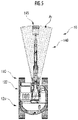
- the degree of possibility of contact between the working mechanism 140 and the unmanned aircraft 40 may alternatively be recognized according to whether the real space position of the unmanned aircraft 40 is included in a reference space determined on the basis of the overall attitude of the working mechanism 140.
- the term "reference space" is defined such that the reference space includes a space that the working mechanism 140 or a part thereof occupies or passes through in a specified period of time when the upper pivoting body 120 pivots with respect to the lower traveling body 110.
- a reference space Ar is defined such that the reference space Ar includes a space that the working mechanism 140 or a part thereof occupies or passes through when the upper pivoting body 120 pivots clockwise or counterclockwise with respect to the lower traveling body 110.
- the overall attitude of the working mechanism 140 and the mode of extension thereof in a vertical direction and the longitudinal direction can be estimated on the basis of the measurement result of the angle of each of the coupling mechanism (or the joint mechanism) for the upper pivoting body 120 and the boom 141, the coupling mechanism for the boom 141 and the arm 143, and the coupling mechanism for the arm 143 and the bucket 145.
- the central angle of the reference space Ar having a substantially fan-shaped cross section corresponds to a pivotable angle of the upper pivoting body 120 with respect to the lower traveling body 110 in a specified period of time.
- the reference space Ar may be defined such that the angle in the counterclockwise direction is larger than the angle in the clockwise direction, i.e., such that the reference space Ar is asymmetrical with reference to the working mechanism 140.
- the contact avoidance operation control element 22 transmits a specified signal to the unmanned aircraft 40 (STEP 212 of FIG. 3 ).
- the "specified signal” is a signal for changing the flight mode of the unmanned aircraft 40, and may include a signal which merely indicates that there is a high possibility of contact with the working mechanism 140 or a command signal instructing a change of the relative position with reference to the working mechanism 140.
- the aircraft control unit 400 receives the specified signal through the wireless communication unit 402 (STEP410 of FIG. 3 ).
- the movements of a plurality of blades are controlled such that the interval between the unmanned aircraft 40 and a specified location on the working mechanism 140 increases, i.e. the unmanned aircraft 40 moves away from the working mechanism 140.
- a flight mode may be preferentially selected, in which the unmanned aircraft 40 ascends from the spot by making use of the characteristics as a rotorcraft.
- the reception of the specified signal or a guidance on an operation mode that is effective for moving the unmanned aircraft 40 away from the working mechanism 140 may be displayed on an output interface constituting the remote control unit 50, and the operator may be notified of the change of the operation mode through an input interface of the remote control unit 50 according to the displayed information.
- the contact avoidance operation control element 22 may transmit a signal which indicates that a change of the flight mode is unnecessary to the unmanned aircraft 40 or the remote control unit 50.
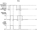
- t t 14 ⁇ t 17 (t 14 ⁇ t 15 , t 16 ⁇ t 17 ) as illustrated in the middle stage of FIG. 6 .
- t t 27 ⁇ t 28 (t 26 ⁇ t 27 , t 28 ⁇ t 29 ) as illustrated in the middle stage of FIG. 7 .
- the contact possibility recognition element 21 recognizes a state of change in the possibility of contact between the working mechanism 140 and the unmanned aircraft 40 based on a state of change in the relative position of the unmanned aircraft 40 with reference to the working mechanism 140 according to the operation mode of at least one of the lower traveling body 110, the upper pivoting body 120, and the working mechanism 140, and the contact avoidance operation control element 22 transmits a specified signal for changing the flight mode of the unmanned aircraft 40 to the unmanned aircraft 40 or the remote control unit 50 of the unmanned aircraft 40 if the contact possibility recognition element 21 recognizes that the contact possibility will be high.
- the flight mode of the unmanned aircraft 40 is changed thereby to reduce the possibility of contact.
- the contact possibility recognition element 21 recognizes the spread state of a reference space encompassing a space that the working mechanism 140 occupies or passes through in a specified period of time on the basis of the operation mode of at least one of the lower traveling body 110, the upper pivoting body 120, and the working mechanism 140 in the specified period of time, and recognizes that the contact possibility is high if the real space position of the unmanned aircraft 40 is included in the reference space.
- the work machine having the configuration when the working mechanism 140 or the like is operated in a specified period of time, the possibility of contact between the working mechanism 140 and the unmanned aircraft 40 in the specified period of time is predicted in advance, and the operation of the unmanned aircraft 40 is controlled, thus further reducing the contact possibility.
- a work machine support server 30 as one embodiment of the present invention illustrated in FIG. 8 has a function for communicating with each of a work machine 10 and an unmanned aircraft 40.
- the work machine support server 30 may be mounted on the unmanned aircraft 40 and may have the function for communicating with the work machine 10.
- the work machine support server 30 includes a contact possibility recognition element 21 and a contact avoidance operation control element 22.
- a work machine control unit 20 may not have such functions as the contact possibility recognition element 21 and the contact avoidance operation control element 22.
- the contact possibility recognition element 21 recognizes that the possibility of contact between a working mechanism 140 and the unmanned aircraft 40 is high, then the contact avoidance operation control element 22 transmits a specified signal to the unmanned aircraft 40.
- an aircraft control unit 400 controls the movement modes of the plurality of blades so as to reduce the contact possibility.
- the possibility of contact between the working mechanism 140 of the work machine 10 and the unmanned aircraft 40 is recognized as being high, then the flight mode of the unmanned aircraft 40 is changed thereby to reduce the contact possibility (refer to FIG. 3 , FIG. 6 , and FIG. 7 ).
Landscapes
- Engineering & Computer Science (AREA)
- Aviation & Aerospace Engineering (AREA)
- General Physics & Mathematics (AREA)
- Radar, Positioning & Navigation (AREA)
- Remote Sensing (AREA)
- Physics & Mathematics (AREA)
- Automation & Control Theory (AREA)
- General Engineering & Computer Science (AREA)
- Structural Engineering (AREA)
- Civil Engineering (AREA)
- Mining & Mineral Resources (AREA)
- Control Of Position, Course, Altitude, Or Attitude Of Moving Bodies (AREA)
- Operation Control Of Excavators (AREA)
Abstract
Description
- The present invention relates to a work machine such as a building demolition machine.
- There has been proposed a technology in which a camera attached to an autonomous flying body is used to image a space that cannot be imaged by a camera attached to an upper pivoting body of an excavator (refer to, for example,
WO2017/131194 ). - However, if an excavator is operated without regard to the position of a flying body, then the possibility of contact between the excavator and the flying body inconveniently increases.
- An object of the present invention is, therefore, to provide mainly a work machine that can reduce the possibility of contact with an unmanned aircraft flying around.
- The present invention relates to a work machine including: a lower traveling body; an upper pivoting body that can pivot with respect to the lower traveling body; a working mechanism that extends from the upper pivoting body; and a control unit that controls the operation mode of each of the lower traveling body, the upper pivoting body, and the working mechanism. Further, the present invention relates to a work machine support server that has a function to communicate with each of the work machine and an unmanned aircraft.
- In the work machine according to the present invention, the control unit includes: a contact possibility recognition element that recognizes a degree of possibility of contact between the working mechanism and the unmanned aircraft according to a relative position of the unmanned aircraft with reference to the working mechanism; and a contact avoidance operation control element which, if the contact possibility recognition element recognizes that a contact possibility is high, transmits a specified signal for changing a flight mode of the unmanned aircraft to the unmanned aircraft or a remote control unit of the unmanned aircraft.
- A work machine support server in accordance with the present invention includes: a contact possibility recognition element which recognizes a degree of possibility of contact between the working mechanism and the unmanned aircraft based on a relative position of the unmanned aircraft with reference to the working mechanism according to communication with at least one of the work machine and the unmanned aircraft; and a contact avoidance operation control element which, if the contact possibility recognition element recognizes that the contact possibility is high, transmits a specified signal for changing a flight mode of the unmanned aircraft to the unmanned aircraft or a remote control unit of the unmanned aircraft.
-
-
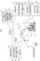
FIG. 1 is an explanatory diagram illustrating the configurations of a work machine and an unmanned aircraft as one embodiment of the present invention; -
FIG. 2 is an explanatory diagram illustrating the configuration of an operating mechanism of the work machine; -
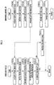
FIG. 3 is an explanatory diagram illustrating the functions of the work machine as one embodiment of the present invention; -
FIG. 4 is an explanatory diagram illustrating an image output mode in an image output unit; -
FIG. 5 is an explanatory diagram illustrating a method for recognizing the degree of possibility of contact between the work machine and the unmanned aircraft; -
FIG. 6 is an explanatory diagram illustrating a first control mode of the working mechanism or the like according to the degree of possibility of contact with the unmanned aircraft; -
FIG. 7 is an explanatory diagram illustrating a second control mode of the working mechanism or the like according to the degree of possibility of contact with the unmanned aircraft; and -
FIG. 8 is an explanatory diagram illustrating the configuration of a work machine support server as one embodiment of the present invention. - A
work machine 10 as one embodiment of the present invention illustrated inFIG. 1 performs predetermined work in collaboration with anunmanned aircraft 40. Thework machine 10 is, for example, a crawler excavator (construction machine), and includes a crawler type lower travelingbody 110 and an upper pivotingbody 120 pivotably mounted on the lower travelingbody 110 through the intermediary of apivoting mechanism 130. A cab (driver compartment) 122 is provided on the left front side of theupper pivoting body 120. A work attachment serving as aworking mechanism 140 is provided at the front center of the upper pivotingbody 120. - The
working mechanism 140 includes aboom 141 liftably attached to theupper pivoting body 120, anarm 143 rotatably connected to the distal end of theboom 141, and abucket 145 rotatably connected to the distal end of thearm 143. Attached to theworking mechanism 140 are aboom cylinder 142, anarm cylinder 144, and abucket cylinder 146 composed of expandable hydraulic cylinders. In place of thebucket 145, other attachment such as a nibbler may be attached to the distal end of thearm 143. - The
boom cylinder 142 is interposed between theboom 141 and the upper pivotingbody 120 so that theboom cylinder 142 expands or contracts by receiving the supply of hydraulic oil thereby to cause theboom 141 to pivot in an upward or downward direction. Thearm cylinder 144 is interposed between thearm 143 and theboom 141 such that thearm cylinder 144 expands or contracts by receiving the supply of hydraulic oil thereby to cause thearm 143 to pivot around a horizontal axis with respect to theboom 141. Thebucket cylinder 146 is interposed between thebucket 145 and thearm 143 such that thebucket cylinder 146 expands or contracts by receiving the supply of hydraulic oil thereby to cause thebucket 145 to pivot around the horizontal axis with respect to thearm 143. - The
work machine 10 includes a workmachine control unit 20, awireless communication unit 202, aninput interface 210, and anoutput interface 220. The workmachine control unit 20 is composed of an arithmetic processing unit (a single-core processor, a multi-core processor, or a processor core that constitutes the single-core processor or the multi-core processor), which reads necessary data and software from a memory or other storage device, and executes arithmetic processing on the data according to the software. - The work
machine control unit 20 includes a contactpossibility recognition element 21 and a contact avoidanceoperation control element 22. The contactpossibility recognition element 21 recognizes the degree of possibility of contact between theworking mechanism 140 and theunmanned aircraft 40 on the basis of the relative position of theunmanned aircraft 40 with reference to theworking mechanism 140. The term "recognition" refers to a concept that encompasses determining, designating or estimating the degree of possibility of contact on the basis of the relative position of theunmanned aircraft 40 with reference to theworking mechanism 140, and receiving a result of the determination or reading from a storage unit. If the contactpossibility recognition element 21 recognizes that the contact possibility is high, then the contact avoidanceoperation control element 22 transmits a specified signal for changing the flight mode of theunmanned aircraft 40 to theunmanned aircraft 40 or aremote control unit 50. - An
operating mechanism 211 constituting theinput interface 210 includes a travel operating unit, a pivoting operating unit, a boom operating unit, an arm operating unit, and a bucket operating unit. Each of the operating units has an operating lever subjected to rotational operations. The operating lever (travel lever) of the travel operating unit is operated to move the lowertraveling body 110. The travel lever may also serve as a travel pedal. For example, a travel pedal fixed to the base or lower end of the travel lever may be provided. The operating lever of the pivoting operating unit (pivoting lever) is operated to move a hydraulic pivoting motor constituting thepivoting mechanism 130. The operating lever of the boom operating unit (boom lever) is operated to move aboom cylinder 142. The operating lever of the arm operating unit (arm lever) is operated to move anarm cylinder 144. An operating lever (bucket lever) of the bucket operating unit is operated to move abucket cylinder 146. - The operating levers constituting the
operating mechanism 211 are placed, for example, around a seat S for an operator to sit on, as illustrated inFIG. 2 . The seat S is in the form of a high-back chair with armrests, but may be in any form that allows an operator to sit thereon, such as a low-back chair without a headrest, or a chair without a backrest. - A pair of left and
right travel levers 2110 corresponding to the left and right crawlers are placed side by side in front of the seat S. A single operating lever may serve as a plurality of operating levers. For example, aright operating lever 2111 provided in front of a right frame of the seat S illustrated inFIG. 3 may function as a boom lever when operated in a longitudinal direction, and may function as a bucket lever when operated in a lateral direction. Similarly, aleft operating lever 2112 provided in front of a left frame of the seat S illustrated inFIG. 3 may function as an arm lever when operated in the longitudinal direction, and may function as a pivoting lever when operated in the lateral direction. The lever pattern may be arbitrarily changed according to an operating instruction of the operator. - An
image output unit 222 constituting theoutput interface 220 is placed, for example, in front of the seat S, as illustrated inFIG. 2 . Theimage output unit 222 may be further provided with a speaker (audio output device). - The
unmanned aircraft 40 includes anaircraft control unit 400, awireless communication unit 402, and animaging unit 410. Theunmanned aircraft 40 may be a constituent element of thework machine 10. In this case, thework machine 10 may be provided with a basement where theunmanned aircraft 40 departs and lands. Theunmanned aircraft 40 is a rotorcraft, and mainly includes a plurality (e.g., four, six, or eight) of blades, an electric motor (actuator) for rotating the plurality of blades, a battery for supplying power to the motor, and the like. Theunmanned aircraft 40 can be operated through a remote control unit. For example, the remote control unit of theunmanned aircraft 40 may be constituted by theinput interface 210. - In the
unmanned aircraft 40, a flight command signal transmitted from theremote control unit 50 is received by theaircraft control unit 400 through the wireless communication unit 402 (STEP402 ofFIG. 3 ). Theaircraft control unit 400 controls the actuator (the electric motor) and the rotational movement of each of the plurality of blades powered by the actuator (STEP404 ofFIG. 3 ). This enables theunmanned aircraft 40 to fly, ascend or descend on the spot, or remain in the air by an airflow generated by the rotation of the plurality of blades. - In the
unmanned aircraft 40, theimaging unit 410 acquires a captured image that includes a specific portion of the workingmechanism 140, such as thebucket 145, which is the distal end portion of an attachment (STEP406 ofFIG. 3 ). Thus, for example, as illustrated on the left side inFIG. 4 , when thework machine 10 is destroying a building, thebucket 145 is imaged from obliquely left front and from above by theimaging unit 410 mounted on theunmanned aircraft 40. The captured image data representing the captured image is transmitted to thework machine 10 by theaircraft control unit 400 through the wireless communication unit 402 (STEP408 ofFIG. 3 ). - In the
work machine 10, the captured image data is received by the workmachine control unit 20 through the wireless communication unit 202 (STEP202 ofFIG. 3 ). By the workmachine control unit 20, an environmental image based on the captured image data (all or a part of the captured image itself or a simulated environmental image generated on the basis thereof) is displayed on the image output unit 222 (STEP204 ofFIG. 3 ). Thus, for example, as illustrated on the right side inFIG. 4 , an environmental image including thebucket 145 when thework machine 10 is destroying the building is displayed on theimage output unit 222. - The work
machine control unit 20 recognizes the relative position of theunmanned aircraft 40 with reference to the working mechanism 140 (STEP206 ofFIG. 3 ). For example, by referring to an image database on the basis of the shape and the size of each of thebucket 145, thearm 143, and theboom 141 in the captured image, the relative position of theunmanned aircraft 40 with reference to a specified location of each of thebucket 145, thearm 143, and theboom 141 is estimated. A marker of a predetermined shape may be attached to a specified location of each of thebucket 145, thearm 143, and theboom 141, and the relative position of theunmanned aircraft 40 may be estimated with reference to the specified location of each of thebucket 145, thearm 143, and theboom 141 by referring to the image database on the basis of the shapes and the sizes of the markers in the captured image. A ranging image sensor or a TOF sensor may be mounted on theunmanned aircraft 40, and the relative position of theunmanned aircraft 40 with reference to the specified location of each of thebucket 145, thearm 143, and theboom 141 may be estimated on the basis of the ranging data acquired through the sensor. - The position (and attitude) of the
unmanned aircraft 40 in a world coordinate system (or a real space coordinate system) may be measured, and the result of the measurement may be transmitted from theunmanned aircraft 40 to thework machine 10 so as to measure the real space position of theunmanned aircraft 40 or the relative position of theunmanned aircraft 40 with reference to the specified location of each of thebucket 145, thearm 143, and theboom 141 by the contactpossibility recognition element 21. - The latitude (Y coordinate value) and the longitude (X coordinate value) in the world coordinate system (or the real space coordinate system) are measured by a positioning device such as a GPS mounted on the
unmanned aircraft 40. The absolute altitude or the air pressure altitude (Z coordinate value) in the world coordinate system is measured by the TOF sensor or an atmospheric pressure sensor. - The position and the attitude of each of the
boom 141, thearm 143, and thebucket 145 in a work machine coordinate system (a coordinate system in which the position and the attitude are fixed with respect to the upper pivoting body 120) are measured on the basis of the angle of each of the coupling mechanism (or a joint mechanism) for theupper pivoting body 120 and theboom 141, the coupling mechanism for theboom 141 and thearm 143, and the coupling mechanism for thearm 143 and thebucket 145, and the size of each of theboom 141, thearm 143, and thebucket 145. The latitudes (Y coordinate values) and the longitudes (X coordinate values) of theupper pivoting body 120 and the work machine coordinate system in the world coordinate system are measured by a positioning system, such as a GPS, mounted on theupper pivoting body 120. The Z coordinate value of the work machine coordinate system in the world coordinate system is determined in advance. The attitude of the work machine coordinate system in the world coordinate system is measured by an azimuth sensor and a tilt angle sensor mounted on theupper pivoting body 120. Thus, the position and the attitude of each of theboom 141, thearm 143, and thebucket 145 in the world coordinate system are measured. - The work
machine control unit 20 recognizes the control mode of each of the operating levers, which constitute theoperating mechanism 211, selected by the operator (STEP208 ofFIG. 3 ). - In the work
machine control unit 20, the contactpossibility recognition element 21 determines whether the possibility of contact between the workingmechanism 140 and theunmanned aircraft 40 is low on the basis of the relative position of theunmanned aircraft 40 with reference to one or a plurality of specified locations of the workingmechanism 140 and the control mode of each of the operating levers constituting theoperating mechanism 211 selected by the operator (STEP210 ofFIG. 3 ). For example, if the interval between a specified location of the workingmechanism 140 and theunmanned aircraft 40 is equal to or less than a predetermined value, and the operation mode of the workingmechanism 140 or the like as a working mechanism according to the control mode of theoperating mechanism 211 is an operation mode that brings the specified location closer to theunmanned aircraft 40, then it is determined that there is a high probability of contact between the workingmechanism 140 and theunmanned aircraft 40. - The degree of possibility of contact between the working
mechanism 140 and theunmanned aircraft 40 may alternatively be recognized according to whether the real space position of theunmanned aircraft 40 is included in a reference space determined on the basis of the overall attitude of the workingmechanism 140. The term "reference space" is defined such that the reference space includes a space that the workingmechanism 140 or a part thereof occupies or passes through in a specified period of time when theupper pivoting body 120 pivots with respect to thelower traveling body 110. For example, as illustrated inFIG. 5 , a reference space Ar is defined such that the reference space Ar includes a space that the workingmechanism 140 or a part thereof occupies or passes through when theupper pivoting body 120 pivots clockwise or counterclockwise with respect to thelower traveling body 110. The overall attitude of the workingmechanism 140 and the mode of extension thereof in a vertical direction and the longitudinal direction can be estimated on the basis of the measurement result of the angle of each of the coupling mechanism (or the joint mechanism) for theupper pivoting body 120 and theboom 141, the coupling mechanism for theboom 141 and thearm 143, and the coupling mechanism for thearm 143 and thebucket 145. - The central angle of the reference space Ar having a substantially fan-shaped cross section corresponds to a pivotable angle of the
upper pivoting body 120 with respect to thelower traveling body 110 in a specified period of time. In a situation in which theupper pivoting body 120 is pivoting counterclockwise with respect to thelower traveling body 110, the reference space Ar may be defined such that the angle in the counterclockwise direction is larger than the angle in the clockwise direction, i.e., such that the reference space Ar is asymmetrical with reference to the workingmechanism 140. - If it is recognized that the possibility of contact between the working
mechanism 140 and theunmanned aircraft 40 is high (NO in STEP210 ofFIG. 3 ), then the contact avoidanceoperation control element 22 transmits a specified signal to the unmanned aircraft 40 (STEP 212 ofFIG. 3 ). The "specified signal" is a signal for changing the flight mode of theunmanned aircraft 40, and may include a signal which merely indicates that there is a high possibility of contact with the workingmechanism 140 or a command signal instructing a change of the relative position with reference to the workingmechanism 140. - In the
unmanned aircraft 40, theaircraft control unit 400 receives the specified signal through the wireless communication unit 402 (STEP410 ofFIG. 3 ). Thus, for example, the movements of a plurality of blades are controlled such that the interval between theunmanned aircraft 40 and a specified location on the workingmechanism 140 increases, i.e. theunmanned aircraft 40 moves away from the workingmechanism 140. A flight mode may be preferentially selected, in which theunmanned aircraft 40 ascends from the spot by making use of the characteristics as a rotorcraft. - When the specified signal is transmitted to the
remote control unit 50, the reception of the specified signal or a guidance on an operation mode that is effective for moving theunmanned aircraft 40 away from the workingmechanism 140 may be displayed on an output interface constituting theremote control unit 50, and the operator may be notified of the change of the operation mode through an input interface of theremote control unit 50 according to the displayed information. - On the other hand, if it is recognized that the possibility of contact between the working
mechanism 140 and theunmanned aircraft 40 is low (YES in STEP210 ofFIG. 3 ), then a series of processing is terminated, and the series of processing is repeated again. In this case, the contact avoidanceoperation control element 22 may transmit a signal which indicates that a change of the flight mode is unnecessary to theunmanned aircraft 40 or theremote control unit 50. - For example, a case will be discussed, where the interval between a specified location of the working
mechanism 140 and theunmanned aircraft 40 is equal to or less than a predetermined value during each of the periods of time t = t10 ∼ t13 and t = t15 ∼ t16 as illustrated in the upper stage ofFIG. 6 , and the operation mode of the workingmechanism 140 or the like is an operation mode in which the interval between the specified location and theunmanned aircraft 40 decreases in each of the periods of time t = t11 ∼ t12 (tio < t11, t12 < t13) and t = t14 ∼ t17 (t14 < t15, t16 < t17) as illustrated in the middle stage ofFIG. 6 . In this case, as illustrated in the lower stage ofFIG. 6 , the flight mode of theunmanned aircraft 40 is changed from a preceding flight mode (the flight mode based on a control mode of the remote control unit 50) in each of the periods of time t = t11 ∼ t12 and t = t15 ∼ t16 during which the interval between the specified location of the workingmechanism 140 and theunmanned aircraft 40 is equal to or less than a predetermined value, and the operation mode of the workingmechanism 140 or the like is an operation mode for approaching to theunmanned aircraft 40. - For example, a case will be discussed, where the interval between a specified location of the working
mechanism 140 and theunmanned aircraft 40 is equal to or less than a predetermined value during each of the periods of time t = t21 ∼ t22 and t = t23 ∼ t24 and t = t26 ∼ t29 as illustrated in the upper stage ofFIG. 7 , and the operation mode of the workingmechanism 140 or the like is an operation mode in which the interval between the specified location and theunmanned aircraft 40 decreases in each of the periods of time t = t20 ∼ t25 (t20 < t21, t24 < t25) and t = t27 ∼ t28 (t26 < t27, t28 < t29) as illustrated in the middle stage ofFIG. 7 . In this case, as illustrated in the lower stage ofFIG. 7 , the flight mode of theunmanned aircraft 40 is changed from a preceding mode (the flight mode based on a control mode of the remote control unit 50) in each of the periods of time t = t21 ∼ t22 and t = t27 ∼ t28 during which the interval between the specified location of the workingmechanism 140 and theunmanned aircraft 40 is equal to or less than a predetermined value, and the operation mode of the workingmechanism 140 or the like is an operation mode for approaching to theunmanned aircraft 40. - If it is recognized that the possibility of contact between the working
mechanism 140 constituting thework machine 10 having the configuration and theunmanned aircraft 40 is high, then the flight behavior of theunmanned aircraft 40 is controlled, thereby reducing the possibility of contact (refer toFIG. 6 andFIG. 7 ). - The contact
possibility recognition element 21 recognizes a state of change in the possibility of contact between the workingmechanism 140 and theunmanned aircraft 40 based on a state of change in the relative position of theunmanned aircraft 40 with reference to the workingmechanism 140 according to the operation mode of at least one of thelower traveling body 110, theupper pivoting body 120, and the workingmechanism 140, and the contact avoidanceoperation control element 22 transmits a specified signal for changing the flight mode of theunmanned aircraft 40 to theunmanned aircraft 40 or theremote control unit 50 of theunmanned aircraft 40 if the contactpossibility recognition element 21 recognizes that the contact possibility will be high. - According to the work machine having the configuration, if it is recognized that maintaining the operation mode of the working
mechanism 140 or the like will lead to a high possibility of contact between the workingmechanism 140 and theunmanned aircraft 40 in the future, then the flight mode of theunmanned aircraft 40 is changed thereby to reduce the possibility of contact. - The contact
possibility recognition element 21 recognizes the spread state of a reference space encompassing a space that the workingmechanism 140 occupies or passes through in a specified period of time on the basis of the operation mode of at least one of thelower traveling body 110, theupper pivoting body 120, and the workingmechanism 140 in the specified period of time, and recognizes that the contact possibility is high if the real space position of theunmanned aircraft 40 is included in the reference space. - According to the work machine having the configuration, when the working
mechanism 140 or the like is operated in a specified period of time, the possibility of contact between the workingmechanism 140 and theunmanned aircraft 40 in the specified period of time is predicted in advance, and the operation of theunmanned aircraft 40 is controlled, thus further reducing the contact possibility. - A work
machine support server 30 as one embodiment of the present invention illustrated inFIG. 8 has a function for communicating with each of awork machine 10 and anunmanned aircraft 40. The workmachine support server 30 may be mounted on theunmanned aircraft 40 and may have the function for communicating with thework machine 10. The workmachine support server 30 includes a contactpossibility recognition element 21 and a contact avoidanceoperation control element 22. In this case, a workmachine control unit 20 may not have such functions as the contactpossibility recognition element 21 and the contact avoidanceoperation control element 22. - According to the work
machine support server 30 having the configuration, if the contactpossibility recognition element 21 recognizes that the possibility of contact between a workingmechanism 140 and theunmanned aircraft 40 is high, then the contact avoidanceoperation control element 22 transmits a specified signal to theunmanned aircraft 40. In response to the specified signal, anaircraft control unit 400 controls the movement modes of the plurality of blades so as to reduce the contact possibility. Thus, if the possibility of contact between the workingmechanism 140 of thework machine 10 and theunmanned aircraft 40 is recognized as being high, then the flight mode of theunmanned aircraft 40 is changed thereby to reduce the contact possibility (refer toFIG. 3 ,FIG. 6 , andFIG. 7 ). - 10 .. work machine; 20 .. work machine control unit; 21 .. contact possibility recognition element; 22 .. contact avoidance operation control element; 30 .. work machine support server; 40 .. unmanned aircraft; 202 .. wireless communication unit; 210 .. input interface; 211 .. operating mechanism; 220 .. output interface; 222 .. image output unit; 140 .. working mechanism (work attachment); 400 .. aircraft control unit; 402 .. wireless communication unit; and 410 .. imaging unit.
Claims (4)
- A work machine comprising: a lower traveling body; an upper pivoting body that can pivot with respect to the lower traveling body; a working mechanism that extends from the upper pivoting body; and a control unit that controls an operation mode of each of the lower traveling body, the upper pivoting body, and the working mechanism,
wherein the control unit includes:a contact possibility recognition element that recognizes a degree of possibility of contact between the working mechanism and an unmanned aircraft based on the relative position of the unmanned aircraft with reference to the working mechanism; anda contact avoidance operation control element which, in a case where the contact possibility recognition element recognizes that the contact possibility is high, transmits a specified signal for changing a flight mode of the unmanned aircraft to the unmanned aircraft or a remote control unit of the unmanned aircraft. - The work machine according to claim 1,
wherein the contact possibility recognition element recognizes a state of change in the possibility of contact between the working mechanism and the unmanned aircraft based on the state of change in the relative position of the unmanned aircraft with reference to the working mechanism according to the operation mode of at least one of the lower traveling body, the upper pivoting body, and the working mechanism, and
in a case where the contact possibility recognition element recognizes that the contact possibility will be high, the contact avoidance operation control element transmits the specified signal for changing the flight mode of the unmanned aircraft to the unmanned aircraft or the remote control unit of the unmanned aircraft - The work machine according to claim 1,
wherein the contact possibility recognition element recognizes a spread state of a reference space encompassing a space that the working mechanism occupies or passes through in one specified period of time based on the operation mode of at least one of the lower traveling body, the upper pivoting body, and the working mechanism in the one specified period of time, and recognizes that the contact possibility is high in a case where a real space position of the unmanned aircraft is included in the reference space. - A work machine support server having a function for communicating with each of an unmanned aircraft and a work machine, the work machine includes a lower traveling body, an upper pivoting body that can pivot with respect to the lower traveling body, a working mechanism that extends from the upper pivoting body, and a control unit that controls an operation mode of each of the lower traveling body, the upper pivoting body, and the working mechanism, comprising:a contact possibility recognition element which recognizes a degree of possibility of contact between the working mechanism and the unmanned aircraft based on a relative position of the unmanned aircraft with reference to the working mechanism according to communication with at least one of the work machine and the unmanned aircraft; anda contact avoidance operation control element which, in a case where the contact possibility recognition element recognizes that the contact possibility is high, transmits a specified signal for changing a flight mode of the unmanned aircraft to the unmanned aircraft or a remote control unit of the unmanned aircraft.
Applications Claiming Priority (1)
| Application Number | Priority Date | Filing Date | Title |
|---|---|---|---|
| JP2019132105A JP7293934B2 (en) | 2019-07-17 | 2019-07-17 | Work machines and work machine support servers |
Publications (2)
| Publication Number | Publication Date |
|---|---|
| EP3767423A1 true EP3767423A1 (en) | 2021-01-20 |
| EP3767423B1 EP3767423B1 (en) | 2022-04-27 |
Family
ID=71527708
Family Applications (1)
| Application Number | Title | Priority Date | Filing Date |
|---|---|---|---|
| EP20184780.3A Active EP3767423B1 (en) | 2019-07-17 | 2020-07-08 | Work machine and work machine support server |
Country Status (3)
| Country | Link |
|---|---|
| US (1) | US20210018937A1 (en) |
| EP (1) | EP3767423B1 (en) |
| JP (1) | JP7293934B2 (en) |
Citations (2)
| Publication number | Priority date | Publication date | Assignee | Title |
|---|---|---|---|---|
| US20080140256A1 (en) * | 2006-09-29 | 2008-06-12 | Kabushiki Kaisha Toshiba | Robot apparatus and control method therefor |
| WO2017131194A1 (en) | 2016-01-29 | 2017-08-03 | 住友建機株式会社 | Excavator and autonomous flying body to fly around excavator |
Family Cites Families (12)
| Publication number | Priority date | Publication date | Assignee | Title |
|---|---|---|---|---|
| US8626361B2 (en) * | 2008-11-25 | 2014-01-07 | Honeywell International Inc. | System and methods for unmanned aerial vehicle navigation |
| KR101483058B1 (en) * | 2014-01-21 | 2015-01-15 | 엘아이지넥스원 주식회사 | Ground control system for UAV anticollision |
| US9896202B2 (en) * | 2014-12-03 | 2018-02-20 | X Development Llc | Systems and methods for reliable relative navigation and autonomous following between unmanned aerial vehicle and a target object |
| GB2533140A (en) * | 2014-12-11 | 2016-06-15 | Caterpillar Inc | Drone |
| JP6674177B2 (en) | 2015-11-25 | 2020-04-01 | 株式会社Ihiエアロスペース | Remote control image acquisition device and method and remote control device |
| CN109074612A (en) | 2016-03-31 | 2018-12-21 | 住友重机械工业株式会社 | Work management system for construction machinery and construction machinery |
| EP3416015A1 (en) * | 2017-06-12 | 2018-12-19 | Dronomy Ltd. | An apparatus and method for operating an unmanned aerial vehicle |
| JP6972692B2 (en) | 2017-06-19 | 2021-11-24 | コベルコ建機株式会社 | Work machine surrounding monitoring system |
| FR3070527B1 (en) * | 2017-08-31 | 2020-11-06 | Airbus Helicopters | METHOD AND DEVICE FOR AVOIDING AN OBJECT BY DETECTION OF ITS APPROACH TO AN AIRCRAFT |
| CN108351652A (en) * | 2017-12-26 | 2018-07-31 | 深圳市道通智能航空技术有限公司 | Unmanned vehicle paths planning method, device and flight management method, apparatus |
| US10720070B2 (en) * | 2018-01-03 | 2020-07-21 | Qualcomm Incorporated | Adjustable object avoidance proximity threshold of a robotic vehicle based on presence of detected payload(s) |
| JP7044694B2 (en) * | 2018-12-27 | 2022-03-30 | ヤンマーパワーテクノロジー株式会社 | Obstacle detection system for work vehicles |
-
2019
- 2019-07-17 JP JP2019132105A patent/JP7293934B2/en active Active
-
2020
- 2020-07-08 EP EP20184780.3A patent/EP3767423B1/en active Active
- 2020-07-14 US US16/928,210 patent/US20210018937A1/en not_active Abandoned
Patent Citations (3)
| Publication number | Priority date | Publication date | Assignee | Title |
|---|---|---|---|---|
| US20080140256A1 (en) * | 2006-09-29 | 2008-06-12 | Kabushiki Kaisha Toshiba | Robot apparatus and control method therefor |
| WO2017131194A1 (en) | 2016-01-29 | 2017-08-03 | 住友建機株式会社 | Excavator and autonomous flying body to fly around excavator |
| EP3409849A1 (en) * | 2016-01-29 | 2018-12-05 | Sumitomo (S.H.I.) Construction Machinery Co., Ltd. | Excavator and autonomous flying body to fly around excavator |
Also Published As
| Publication number | Publication date |
|---|---|
| EP3767423B1 (en) | 2022-04-27 |
| US20210018937A1 (en) | 2021-01-21 |
| JP7293934B2 (en) | 2023-06-20 |
| JP2021017695A (en) | 2021-02-15 |
Similar Documents
| Publication | Publication Date | Title |
|---|---|---|
| EP4265857B1 (en) | Work assistance system and work assistance composite system | |
| CN115279974A (en) | Construction support system for excavator | |
| CN114787453B (en) | Remote operating device and remote operating system | |
| JP6829513B1 (en) | Position calculation method and information processing system | |
| US20250052033A1 (en) | Image display system, remote operation assistance system, and image display method | |
| JP2018181116A (en) | Unmanned aerial vehicle, position estimation device, flight control device, position estimation method, control method and program | |
| AU2025203439A1 (en) | Construction management system, data processing device, and construction management method | |
| JP2024096122A (en) | Work Support Device | |
| EP4044101B1 (en) | Work assistance server, work assistance method, and work assistance system | |
| EP3767423B1 (en) | Work machine and work machine support server | |
| EP3767418B1 (en) | Work machine and work machine support server | |
| JP7754233B2 (en) | Remote operation support device and remote operation support system | |
| EP3767040A1 (en) | Work machine and work machine support server | |
| JP2021017761A (en) | Work machine and work machine supporting server | |
| JP2025105249A (en) | System for work machine and excavator | |
| JP7443978B2 (en) | Work support equipment | |
| JP7472708B2 (en) | Work Support Device | |
| KR102070110B1 (en) | Intelligent agent structure for autonomous unmanned system | |
| JP2022129500A (en) | Terrain information management system and work machine | |
| JP2021025240A (en) | Work machine and work machine support server | |
| JP2021021253A (en) | Work machine and work machine assistance server | |
| JP2025167567A (en) | Remote control system for work machines | |
| CN121752788A (en) | Operation assisting system and operation assisting method | |
| WO2025134493A1 (en) | Construction assistance system, construction assistance method, and construction assistance program | |
| WO2024241712A1 (en) | Information system and operation device |
Legal Events
| Date | Code | Title | Description |
|---|---|---|---|
| PUAI | Public reference made under article 153(3) epc to a published international application that has entered the european phase |
Free format text: ORIGINAL CODE: 0009012 |
|
| STAA | Information on the status of an ep patent application or granted ep patent |
Free format text: STATUS: THE APPLICATION HAS BEEN PUBLISHED |
|
| AK | Designated contracting states |
Kind code of ref document: A1 Designated state(s): AL AT BE BG CH CY CZ DE DK EE ES FI FR GB GR HR HU IE IS IT LI LT LU LV MC MK MT NL NO PL PT RO RS SE SI SK SM TR |
|
| AX | Request for extension of the european patent |
Extension state: BA ME |
|
| RIN1 | Information on inventor provided before grant (corrected) |
Inventor name: FUJITA, SHUHEI Inventor name: EITA, AKIHIKO |
|
| STAA | Information on the status of an ep patent application or granted ep patent |
Free format text: STATUS: REQUEST FOR EXAMINATION WAS MADE |
|
| 17P | Request for examination filed |
Effective date: 20210719 |
|
| RBV | Designated contracting states (corrected) |
Designated state(s): AL AT BE BG CH CY CZ DE DK EE ES FI FR GB GR HR HU IE IS IT LI LT LU LV MC MK MT NL NO PL PT RO RS SE SI SK SM TR |
|
| GRAP | Despatch of communication of intention to grant a patent |
Free format text: ORIGINAL CODE: EPIDOSNIGR1 |
|
| STAA | Information on the status of an ep patent application or granted ep patent |
Free format text: STATUS: GRANT OF PATENT IS INTENDED |
|
| INTG | Intention to grant announced |
Effective date: 20211122 |
|
| GRAS | Grant fee paid |
Free format text: ORIGINAL CODE: EPIDOSNIGR3 |
|
| GRAA | (expected) grant |
Free format text: ORIGINAL CODE: 0009210 |
|
| STAA | Information on the status of an ep patent application or granted ep patent |
Free format text: STATUS: THE PATENT HAS BEEN GRANTED |
|
| AK | Designated contracting states |
Kind code of ref document: B1 Designated state(s): AL AT BE BG CH CY CZ DE DK EE ES FI FR GB GR HR HU IE IS IT LI LT LU LV MC MK MT NL NO PL PT RO RS SE SI SK SM TR |
|
| REG | Reference to a national code |
Ref country code: GB Ref legal event code: FG4D |
|
| REG | Reference to a national code |
Ref country code: CH Ref legal event code: EP |
|
| REG | Reference to a national code |
Ref country code: AT Ref legal event code: REF Ref document number: 1487430 Country of ref document: AT Kind code of ref document: T Effective date: 20220515 |
|
| REG | Reference to a national code |
Ref country code: DE Ref legal event code: R096 Ref document number: 602020002824 Country of ref document: DE |
|
| REG | Reference to a national code |
Ref country code: IE Ref legal event code: FG4D |
|
| REG | Reference to a national code |
Ref country code: LT Ref legal event code: MG9D |
|
| REG | Reference to a national code |
Ref country code: NL Ref legal event code: MP Effective date: 20220427 |
|
| REG | Reference to a national code |
Ref country code: AT Ref legal event code: MK05 Ref document number: 1487430 Country of ref document: AT Kind code of ref document: T Effective date: 20220427 |
|
| PG25 | Lapsed in a contracting state [announced via postgrant information from national office to epo] |
Ref country code: NL Free format text: LAPSE BECAUSE OF FAILURE TO SUBMIT A TRANSLATION OF THE DESCRIPTION OR TO PAY THE FEE WITHIN THE PRESCRIBED TIME-LIMIT Effective date: 20220427 |
|
| PG25 | Lapsed in a contracting state [announced via postgrant information from national office to epo] |
Ref country code: SE Free format text: LAPSE BECAUSE OF FAILURE TO SUBMIT A TRANSLATION OF THE DESCRIPTION OR TO PAY THE FEE WITHIN THE PRESCRIBED TIME-LIMIT Effective date: 20220427 Ref country code: PT Free format text: LAPSE BECAUSE OF FAILURE TO SUBMIT A TRANSLATION OF THE DESCRIPTION OR TO PAY THE FEE WITHIN THE PRESCRIBED TIME-LIMIT Effective date: 20220829 Ref country code: NO Free format text: LAPSE BECAUSE OF FAILURE TO SUBMIT A TRANSLATION OF THE DESCRIPTION OR TO PAY THE FEE WITHIN THE PRESCRIBED TIME-LIMIT Effective date: 20220727 Ref country code: LT Free format text: LAPSE BECAUSE OF FAILURE TO SUBMIT A TRANSLATION OF THE DESCRIPTION OR TO PAY THE FEE WITHIN THE PRESCRIBED TIME-LIMIT Effective date: 20220427 Ref country code: HR Free format text: LAPSE BECAUSE OF FAILURE TO SUBMIT A TRANSLATION OF THE DESCRIPTION OR TO PAY THE FEE WITHIN THE PRESCRIBED TIME-LIMIT Effective date: 20220427 Ref country code: GR Free format text: LAPSE BECAUSE OF FAILURE TO SUBMIT A TRANSLATION OF THE DESCRIPTION OR TO PAY THE FEE WITHIN THE PRESCRIBED TIME-LIMIT Effective date: 20220728 Ref country code: FI Free format text: LAPSE BECAUSE OF FAILURE TO SUBMIT A TRANSLATION OF THE DESCRIPTION OR TO PAY THE FEE WITHIN THE PRESCRIBED TIME-LIMIT Effective date: 20220427 Ref country code: BG Free format text: LAPSE BECAUSE OF FAILURE TO SUBMIT A TRANSLATION OF THE DESCRIPTION OR TO PAY THE FEE WITHIN THE PRESCRIBED TIME-LIMIT Effective date: 20220727 Ref country code: AT Free format text: LAPSE BECAUSE OF FAILURE TO SUBMIT A TRANSLATION OF THE DESCRIPTION OR TO PAY THE FEE WITHIN THE PRESCRIBED TIME-LIMIT Effective date: 20220427 |
|
| PG25 | Lapsed in a contracting state [announced via postgrant information from national office to epo] |
Ref country code: RS Free format text: LAPSE BECAUSE OF FAILURE TO SUBMIT A TRANSLATION OF THE DESCRIPTION OR TO PAY THE FEE WITHIN THE PRESCRIBED TIME-LIMIT Effective date: 20220427 Ref country code: PL Free format text: LAPSE BECAUSE OF FAILURE TO SUBMIT A TRANSLATION OF THE DESCRIPTION OR TO PAY THE FEE WITHIN THE PRESCRIBED TIME-LIMIT Effective date: 20220427 Ref country code: LV Free format text: LAPSE BECAUSE OF FAILURE TO SUBMIT A TRANSLATION OF THE DESCRIPTION OR TO PAY THE FEE WITHIN THE PRESCRIBED TIME-LIMIT Effective date: 20220427 Ref country code: IS Free format text: LAPSE BECAUSE OF FAILURE TO SUBMIT A TRANSLATION OF THE DESCRIPTION OR TO PAY THE FEE WITHIN THE PRESCRIBED TIME-LIMIT Effective date: 20220827 |
|
| REG | Reference to a national code |
Ref country code: DE Ref legal event code: R097 Ref document number: 602020002824 Country of ref document: DE |
|
| PG25 | Lapsed in a contracting state [announced via postgrant information from national office to epo] |
Ref country code: SM Free format text: LAPSE BECAUSE OF FAILURE TO SUBMIT A TRANSLATION OF THE DESCRIPTION OR TO PAY THE FEE WITHIN THE PRESCRIBED TIME-LIMIT Effective date: 20220427 Ref country code: SK Free format text: LAPSE BECAUSE OF FAILURE TO SUBMIT A TRANSLATION OF THE DESCRIPTION OR TO PAY THE FEE WITHIN THE PRESCRIBED TIME-LIMIT Effective date: 20220427 Ref country code: RO Free format text: LAPSE BECAUSE OF FAILURE TO SUBMIT A TRANSLATION OF THE DESCRIPTION OR TO PAY THE FEE WITHIN THE PRESCRIBED TIME-LIMIT Effective date: 20220427 Ref country code: ES Free format text: LAPSE BECAUSE OF FAILURE TO SUBMIT A TRANSLATION OF THE DESCRIPTION OR TO PAY THE FEE WITHIN THE PRESCRIBED TIME-LIMIT Effective date: 20220427 Ref country code: EE Free format text: LAPSE BECAUSE OF FAILURE TO SUBMIT A TRANSLATION OF THE DESCRIPTION OR TO PAY THE FEE WITHIN THE PRESCRIBED TIME-LIMIT Effective date: 20220427 Ref country code: DK Free format text: LAPSE BECAUSE OF FAILURE TO SUBMIT A TRANSLATION OF THE DESCRIPTION OR TO PAY THE FEE WITHIN THE PRESCRIBED TIME-LIMIT Effective date: 20220427 Ref country code: CZ Free format text: LAPSE BECAUSE OF FAILURE TO SUBMIT A TRANSLATION OF THE DESCRIPTION OR TO PAY THE FEE WITHIN THE PRESCRIBED TIME-LIMIT Effective date: 20220427 |
|
| PG25 | Lapsed in a contracting state [announced via postgrant information from national office to epo] |
Ref country code: MC Free format text: LAPSE BECAUSE OF FAILURE TO SUBMIT A TRANSLATION OF THE DESCRIPTION OR TO PAY THE FEE WITHIN THE PRESCRIBED TIME-LIMIT Effective date: 20220427 |
|
| PLBE | No opposition filed within time limit |
Free format text: ORIGINAL CODE: 0009261 |
|
| STAA | Information on the status of an ep patent application or granted ep patent |
Free format text: STATUS: NO OPPOSITION FILED WITHIN TIME LIMIT |
|
| REG | Reference to a national code |
Ref country code: BE Ref legal event code: MM Effective date: 20220731 |
|
| PG25 | Lapsed in a contracting state [announced via postgrant information from national office to epo] |
Ref country code: AL Free format text: LAPSE BECAUSE OF FAILURE TO SUBMIT A TRANSLATION OF THE DESCRIPTION OR TO PAY THE FEE WITHIN THE PRESCRIBED TIME-LIMIT Effective date: 20220427 |
|
| 26N | No opposition filed |
Effective date: 20230130 |
|
| PG25 | Lapsed in a contracting state [announced via postgrant information from national office to epo] |
Ref country code: LU Free format text: LAPSE BECAUSE OF NON-PAYMENT OF DUE FEES Effective date: 20220708 |
|
| PG25 | Lapsed in a contracting state [announced via postgrant information from national office to epo] |
Ref country code: SI Free format text: LAPSE BECAUSE OF FAILURE TO SUBMIT A TRANSLATION OF THE DESCRIPTION OR TO PAY THE FEE WITHIN THE PRESCRIBED TIME-LIMIT Effective date: 20220427 Ref country code: BE Free format text: LAPSE BECAUSE OF NON-PAYMENT OF DUE FEES Effective date: 20220731 |
|
| PG25 | Lapsed in a contracting state [announced via postgrant information from national office to epo] |
Ref country code: IE Free format text: LAPSE BECAUSE OF NON-PAYMENT OF DUE FEES Effective date: 20220708 |
|
| PGFP | Annual fee paid to national office [announced via postgrant information from national office to epo] |
Ref country code: FR Payment date: 20230620 Year of fee payment: 4 |
|
| PGFP | Annual fee paid to national office [announced via postgrant information from national office to epo] |
Ref country code: IT Payment date: 20230731 Year of fee payment: 4 |
|
| REG | Reference to a national code |
Ref country code: DE Ref legal event code: R079 Ref document number: 602020002824 Country of ref document: DE Free format text: PREVIOUS MAIN CLASS: G05D0001100000 Ipc: G05D0001460000 |
|
| REG | Reference to a national code |
Ref country code: CH Ref legal event code: PL |
|
| PG25 | Lapsed in a contracting state [announced via postgrant information from national office to epo] |
Ref country code: MK Free format text: LAPSE BECAUSE OF FAILURE TO SUBMIT A TRANSLATION OF THE DESCRIPTION OR TO PAY THE FEE WITHIN THE PRESCRIBED TIME-LIMIT Effective date: 20220427 Ref country code: CY Free format text: LAPSE BECAUSE OF FAILURE TO SUBMIT A TRANSLATION OF THE DESCRIPTION OR TO PAY THE FEE WITHIN THE PRESCRIBED TIME-LIMIT Effective date: 20220427 Ref country code: CH Free format text: LAPSE BECAUSE OF NON-PAYMENT OF DUE FEES Effective date: 20230731 |
|
| PG25 | Lapsed in a contracting state [announced via postgrant information from national office to epo] |
Ref country code: HU Free format text: LAPSE BECAUSE OF FAILURE TO SUBMIT A TRANSLATION OF THE DESCRIPTION OR TO PAY THE FEE WITHIN THE PRESCRIBED TIME-LIMIT; INVALID AB INITIO Effective date: 20200708 |
|
| PG25 | Lapsed in a contracting state [announced via postgrant information from national office to epo] |
Ref country code: TR Free format text: LAPSE BECAUSE OF FAILURE TO SUBMIT A TRANSLATION OF THE DESCRIPTION OR TO PAY THE FEE WITHIN THE PRESCRIBED TIME-LIMIT Effective date: 20220427 |
|
| PGFP | Annual fee paid to national office [announced via postgrant information from national office to epo] |
Ref country code: GB Payment date: 20240530 Year of fee payment: 5 |
|
| PG25 | Lapsed in a contracting state [announced via postgrant information from national office to epo] |
Ref country code: MT Free format text: LAPSE BECAUSE OF FAILURE TO SUBMIT A TRANSLATION OF THE DESCRIPTION OR TO PAY THE FEE WITHIN THE PRESCRIBED TIME-LIMIT Effective date: 20220427 |
|
| PGFP | Annual fee paid to national office [announced via postgrant information from national office to epo] |
Ref country code: DE Payment date: 20240529 Year of fee payment: 5 |
|
| PG25 | Lapsed in a contracting state [announced via postgrant information from national office to epo] |
Ref country code: BG Free format text: LAPSE BECAUSE OF FAILURE TO SUBMIT A TRANSLATION OF THE DESCRIPTION OR TO PAY THE FEE WITHIN THE PRESCRIBED TIME-LIMIT Effective date: 20220427 |
|
| PG25 | Lapsed in a contracting state [announced via postgrant information from national office to epo] |
Ref country code: BG Free format text: LAPSE BECAUSE OF FAILURE TO SUBMIT A TRANSLATION OF THE DESCRIPTION OR TO PAY THE FEE WITHIN THE PRESCRIBED TIME-LIMIT Effective date: 20220427 |
|
| PG25 | Lapsed in a contracting state [announced via postgrant information from national office to epo] |
Ref country code: FR Free format text: LAPSE BECAUSE OF NON-PAYMENT OF DUE FEES Effective date: 20240731 |
|
| PG25 | Lapsed in a contracting state [announced via postgrant information from national office to epo] |
Ref country code: IT Free format text: LAPSE BECAUSE OF NON-PAYMENT OF DUE FEES Effective date: 20240708 |
|
| REG | Reference to a national code |
Ref country code: DE Ref legal event code: R119 Ref document number: 602020002824 Country of ref document: DE |
|
| GBPC | Gb: european patent ceased through non-payment of renewal fee |
Effective date: 20250708 |
|
| PG25 | Lapsed in a contracting state [announced via postgrant information from national office to epo] |
Ref country code: GB Free format text: LAPSE BECAUSE OF NON-PAYMENT OF DUE FEES Effective date: 20250708 |
|
| PG25 | Lapsed in a contracting state [announced via postgrant information from national office to epo] |
Ref country code: DE Free format text: LAPSE BECAUSE OF NON-PAYMENT OF DUE FEES Effective date: 20260203 |