EP3767412A1 - Ladder diagram program generation assistance device, ladder diagram program generation assistance method, and ladder diagram program generation assistance program - Google Patents
Ladder diagram program generation assistance device, ladder diagram program generation assistance method, and ladder diagram program generation assistance program Download PDFInfo
- Publication number
- EP3767412A1 EP3767412A1 EP19768213.1A EP19768213A EP3767412A1 EP 3767412 A1 EP3767412 A1 EP 3767412A1 EP 19768213 A EP19768213 A EP 19768213A EP 3767412 A1 EP3767412 A1 EP 3767412A1
- Authority
- EP
- European Patent Office
- Prior art keywords
- input
- ladder
- circuit
- partial circuit
- unit
- Prior art date
- Legal status (The legal status is an assumption and is not a legal conclusion. Google has not performed a legal analysis and makes no representation as to the accuracy of the status listed.)
- Granted
Links
Images





Classifications
-
- G—PHYSICS
- G05—CONTROLLING; REGULATING
- G05B—CONTROL OR REGULATING SYSTEMS IN GENERAL; FUNCTIONAL ELEMENTS OF SUCH SYSTEMS; MONITORING OR TESTING ARRANGEMENTS FOR SUCH SYSTEMS OR ELEMENTS
- G05B19/00—Program-control systems
- G05B19/02—Program-control systems electric
- G05B19/04—Program control other than numerical control, i.e. in sequence controllers or logic controllers
- G05B19/05—Programmable logic controllers, e.g. simulating logic interconnections of signals according to ladder diagrams or function charts
- G05B19/056—Programming the PLC
-
- G—PHYSICS
- G05—CONTROLLING; REGULATING
- G05B—CONTROL OR REGULATING SYSTEMS IN GENERAL; FUNCTIONAL ELEMENTS OF SUCH SYSTEMS; MONITORING OR TESTING ARRANGEMENTS FOR SUCH SYSTEMS OR ELEMENTS
- G05B2219/00—Program-control systems
- G05B2219/10—Plc systems
- G05B2219/13—Plc programming
- G05B2219/13052—Display of ladder diagram
-
- G—PHYSICS
- G05—CONTROLLING; REGULATING
- G05B—CONTROL OR REGULATING SYSTEMS IN GENERAL; FUNCTIONAL ELEMENTS OF SUCH SYSTEMS; MONITORING OR TESTING ARRANGEMENTS FOR SUCH SYSTEMS OR ELEMENTS
- G05B2219/00—Program-control systems
- G05B2219/10—Plc systems
- G05B2219/13—Plc programming
- G05B2219/13053—Edit by use of a ladder mask, raster, enter a symbol and select place in mask
Definitions
- the present invention relates to a technology for assisting with generation and editing of a ladder diagram program executed by a programmable controller (PLC).
- PLC programmable controller
- ladder diagram programs executed by programmable controllers are generated by general-purpose computers such as personal computers and are uploaded to the PLCs in many cases.
- programs that perform a generation and editing function of generating and editing a ladder diagram program, an upload function of uploading the ladder diagram program to PLCs, a download function of downloading the ladder diagram program from PLCs, and the like are installed.
- Patent Literature 1 facilitates an input of a variable name described as an operand of a command.
- a plurality of variables has variable names differentiated by suffixing numbers, signs, or the like to the same character strings, an input of variable names is facilitated.
- Patent Literature 1 when one character of a character string that forms a variable name is input, all the variable names whose prefix matches character strings (confirmed character strings) confirmed by then and character strings formed by the one character presently input are extracted from a variable table.
- the variable name when the number of extracted variable names is single, the variable name is confirmed as an operand.
- the number of extracted variable names is plural, character strings of portions whose prefixes match all the extracted variable names are set as confirmed character strings.
- an input of one character subsequent to the confirmed character string is received again and the foregoing operation is repeated.
- Patent Literature 1 Japanese Patent Application Laid-Open No. 2010-238225
- Patent Literature 1 An input of a variable name described as an operand of a command is facilitated in Patent Literature 1.
- an improvement in efficiency of generation and editing jobs of the ladder diagram program in which the same ladder circuit or similar ladder circuits appear repeatedly is not realized. More specifically, an operator may not simply perform an operation of inputting the same ladder circuit or similar ladder circuits appearing repeatedly in the ladder diagram program which is being generated and edited.
- the ladder circuits mentioned here are circuits that have a logical meaning and are function blocks (FB), contacts, or the like.
- the similar ladder circuits are circuits that have the same logical meaning and different input variables.
- An objective of the invention is to provide a technology for improving generation and editing efficiency of a ladder diagram program in which the same ladder circuit or similar ladder circuits repeatedly appear.
- a ladder diagram program generation assistance device is configured as follows to achieve the objective of the invention.
- An input unit receives an input related to generation and editing of a ladder diagram program.
- a partial circuit search unit when the input unit receives a command name of the ladder circuit to be inserted into the ladder diagram program, searches for and extracts a partial circuit corresponding to a ladder circuit with the input command name. For example, the partial circuit search unit extracts a partial circuit including a ladder circuit that has a command name which is the same as the input command name.
- the partial circuit mentioned here may be a single ladder circuit that has a logical meaning or may include a plurality of ladder circuits that have a logical meaning.
- An input candidate output unit outputs an input candidate corresponding to the partial circuit extracted by the partial circuit search unit.
- a replacement processing unit when a selection of the input candidate output by the input candidate output unit is received, replaces, with the selected input candidate, the ladder circuit of which the command name has been input by the input unit.
- an operator can perform an operation of inputting the same ladder circuit or similar ladder circuits appearing repeatedly by performing a simple operation of inputting the command name of the ladder circuit and selecting the output input candidate in the generated and edited ladder diagram program. Accordingly, it is possible to improve efficiency of generation and editing of the ladder diagram program in which the same ladder circuit or similar ladder circuits appear repeatedly.
- the partial circuit search unit may search for a ladder circuit that has a command name which is the same as the command name input in the input unit and repeatedly appears a predetermined number of times or more in the ladder diagram program which is being generated or edited, and extracts a partial circuit in accordance with the searched ladder circuit.
- the input candidate to be output is a partial circuit including a ladder circuit of which a command name is input by the operation.
- variable setting unit that sets a variable of the partial circuit extracted by the partial circuit search unit may be included and the input candidate output unit may output the partial circuit in which the variable is set by the variable setting unit as an input candidate.
- the variable setting unit may set the variable of the partial circuit extracted by the partial circuit search unit in accordance with the variable of the ladder circuit that has a command name which is the same as the command name input in the input unit and appears repeatedly a plurality number of times in the ladder diagram program which is being generated or edited.
- the partial circuit search unit may also search for and extract a partial circuit corresponding to a ladder circuit with an input variable name when the input unit receives a variable name of the ladder circuit to be inserted into the ladder diagram program.
- the input candidate output unit outputs an input candidate corresponding to the partial circuit extracted by the partial circuit search unit.
- the replacement processing unit replaces, with the selected input candidate, the ladder circuit of which the variable name has been input when a selection of the input candidate output by the input candidate output unit is received. In this configuration, it is also possible to improve efficiency of generation and editing of the ladder diagram program in which the same ladder circuit or similar ladder circuits appear repeatedly.
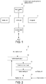
- Fig. 1 is a block diagram illustrating a configuration of main units of a ladder diagram program generation assistance device according to the example.
- a ladder diagram program generation assistance device 1 according to the example includes a control unit 2, an input operation unit 3, a display unit 4, a storage unit 5, and an input and output unit 6.
- the ladder diagram program generation assistance device 1 can be realized by a general-purpose computer in which a program that performs a generation and editing function of generating and editing a ladder diagram program, an upload function of uploading the ladder diagram to a PLC, a download function of downloading the ladder diagram program from a PLC, and the like is installed.
- the computer performs a ladder diagram program generation assistance method according to the invention.
- a ladder diagram program generation assistance program according to the invention is installed in the computer.
- the control unit 2 controls an operation of each unit of the body of the ladder diagram program generation assistance device 1.
- the input operation unit 3 includes an input device such as a keyboard or a mouse and receives an input in response to an operation on the input device by the operator.
- the input operation unit 3 is equivalent to an input unit mentioned in the invention.
- the display unit 4 includes a display device such as a display and controls screen display in the display device.
- the display unit 4 causes the display to display a state or the like of the ladder diagram program generated and edited at that time or the body of the ladder diagram program generation assistance device 1 at that time.
- the display unit 4 is equivalent to an input candidate output unit mentioned in the invention.
- the storage unit 5 includes a storage medium such as a hard disk or a memory and stores a program necessary for an operation of the body of the ladder diagram program generation assistance device 1, data, and a ladder diagram program.
- the input and output unit 6 performs input and output of the ladder diagram program (upload or download of the ladder diagram program) to and from a programmable controller (PLC) (not illustrated).
- PLC programmable controller
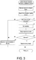
- Fig. 2 is a block diagram illustrating a functional configuration of a control unit.
- the control unit 2 includes a partial circuit search unit 21, a variable setting unit 22, and a replacement processing unit 23.
- a ladder diagram program 20 illustrated in Fig. 2 is a program generated and edited at that time and is loaded on the control unit 2.
- the partial circuit search unit 21 searches for a partial circuit corresponding to a command name of a function block (FB) for a ladder circuit input to the ladder diagram program 20 processed at a time when the operator operates the input operation unit 3.
- the ladder circuit mentioned here is a circuit that has a logical meaning and includes not only an FB but also a circuit element such as a contact.
- the partial circuit mentioned here may be a single ladder circuit that has a logical meaning or may include a plurality of ladder circuits that have a logical meaning.
- the partial circuit search unit 21 searches for a partial circuit in the ladder diagram program 20 processed at that time (the partial circuit search unit 21 does not search for a partial circuit with regard to another ladder diagram program stored in the storage unit 5 or the like).
- the partial circuit search unit 21 searches for an FB that has a command name which is the same as the input command name in the ladder diagram program 20 processed at that time and extracts a partial circuit including the FB.
- the partial circuit search unit 21 searches for an FB that has a command name which is the same as the input command name in the ladder diagram program 20 processed at that time and that has already appeared a predetermined number of times (for example, a plurality of times such as twice or three times) or more in the ladder diagram program 20.
- the variable setting unit 22 sets a variable in the partial circuit extracted by the partial circuit search unit 21.
- the variable setting unit 22 sets variables in a partial circuit presently extracted by the partial circuit search unit 21 in accordance with variables of a plurality of partial circuits searched for by the partial circuit search unit 21. For example, when the variables of the plurality of partial circuits searched for by the partial circuit search unit 21 are constant, the variable setting unit 22 sets variables with the same value.
- the variable setting unit 22 estimates and sets variables on the basis of this rule.
- the variable is a structure
- the variable setting unit 22 sets model-matched variables which are estimated based on the variables of the plurality of partial circuits searched for by the partial circuit search unit 21.
- variable setting unit 22 estimates and sets signs of the suffixes based on the variables of the plurality of partial circuits searched for by the partial circuit search unit 21.
- a partial circuit in which the variables are set by the variable setting unit 22 is output as an input candidate.
- the display unit 4 displays the partial circuit in which the variables are set by the variable setting unit 22 as an input candidate on the display device.
- the replacement processing unit 23 replaces the FB to which the current command name is input in the ladder diagram program 20 processed at that time with the selected input candidate (the partial circuit in which the variables are set by the variable setting unit 22).
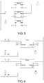
- Fig. 3 is a flowchart illustrating an operation of the ladder diagram program generation assistance device 1 according to the example.
- the ladder diagram program generation assistance device 1 loads the ladder diagram program 20 generated and edited at that time in the control unit 2.
- the operator performs an input operation related to the generation and editing of the ladder diagram program 20 in the input operation unit 3.
- the partial circuit search unit 21 searches for and extracts partial circuits (s2).
- a search range in which the partial circuit search unit 21 searches for the partial circuits is a range from the first row of the ladder diagram program 20 generated and edited at that time to a row in which the FBs with the presently input command name are added.
- the partial circuit search unit 21 searches for the FBs that have a command name which is the same as the presently input command name and that have already appeared repeatedly a predetermined number of times (for example, a plurality of times such as twice or three times) or more in the search range of the ladder diagram program 20.
- a predetermined number of times for example, a plurality of times such as twice or three times
- the partial circuit search unit 21 determines that there are no partial circuits corresponding to the FBs with the presently input command name.
- the partial circuit search unit 21 When the partial circuit search unit 21 can search for the FBs satisfying the foregoing condition and other ladder circuits connected to the FBs are common between the searched FBs, the partial circuit search unit 21 extracts a circuit formed by the searched FBs and the other common ladder circuits as a partial circuit. In other words, when the partial circuit search unit 21 can search for the FBs satisfying the condition and other ladder circuits connected to the FBs are not common between the searched FBs, the partial circuit search unit 21 extracts the searched FB as a partial circuit.
- the variable setting unit 22 sets variables for the extracted partial circuits (s3 and s4). In s4, the variable setting unit 22 sets variables of the partial circuits which are presently input candidates in accordance with the variables of the ladder circuits searched for in s2, that is, the partial circuits (the partial circuits extracted in s2) including the FBs that have the same command name and have already appeared in the ladder diagram program 20 generated and edited at that time. For example, when the variables of the plurality of partial circuits searched for by the partial circuit search unit 21 are constant, the variable setting unit 22 sets the variables of the partial circuits which are the presently input candidates to the same value.
- variable setting unit 22 estimates and sets the variables of the partial circuits which are the presently input candidates based on this rule.
- the variable setting unit 22 sets the variables of the partial circuits which are the present input candidates to model-matched variables which are estimated based on the variables of the plurality of partial circuits searched for by the partial circuit search unit 21.
- the variable setting unit 22 sets the variables of the partial circuits which are the present input candidates by estimating signs of the suffixes based on the variables of the plurality of partial circuits searched for by the partial circuit search unit 21.
- the ladder diagram program generation assistance device 1 outputs the partial circuits with the variables set in s4 as input candidates (s5).
- the display unit 4 displays the input candidates on the display device.
- the operator performs an operation of selecting an input candidate in the input operation unit 3.
- the replacement processing unit 23 replaces the FB with the currently input command name with the partial circuit which is the selected input candidate (s6 and s7) and the process returns to s1.
- the ladder diagram program generation assistance device 1 receives the operation by the operator (s6 and s8) and the process returns to s1. In s8, setting of the variables or the like is performed in response to the input operation by the operator.
- the operator can perform an operation of inputting the same ladder circuit (the ladder circuit including the FB) or similar ladder circuits (the ladder circuits including the FBs) appearing repeatedly by performing a simple operation of inputting the command names of the FBs and selecting the output input candidate in the generated and edited ladder diagram program. Accordingly, it is possible to improve efficiency of generation and editing of the ladder diagram program in which the same ladder circuit (the ladder circuit including the FB) or similar ladder circuits (the ladder circuits including the FBs) appear repeatedly.
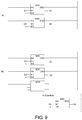
- FIG. 4 is a diagram illustrating screen display of the display device before a command name of an FB is input.
- (B) of Fig. 4 is a diagram illustrating screen display of the display device after the command name of the FB is input.
- Fig. 5 is a diagram illustrating screen display of the display device after an input candidate is selected.
- Y illustrated in (A) and (B) of Fig. 4 , and 5 indicates a coil.
- the FB with the input command name is replaced with the partial circuit which is the selected input candidate.
- Fig. 6 is a diagram illustrating screen display of the display device before a command name of an FB is input.
- Fig. 7 is a diagram illustrating screen display of the display device after the command name of the FB is input.
- Fig. 8 is a diagram illustrating screen display of the display device after an input candidate is selected.
- the ladder diagram program As illustrated in Fig. 6 , the ladder diagram program according to this example, two FBs with a command name Timer have already appeared.
- a partial circuit which is an input candidate is displayed on the display device.
- the input variables of the partial circuit which is the input candidate are estimated to be [X2, T2] since input variables of two FBs that have the command name Timer and have already appeared are [X0, T0] and [X1, T1].
- An output variable of the partial circuit which is the input candidate is estimated to be [Y2, T2] since the output variables of the two FBs that have the command name Timer and have already appeared are [Y0, T0] and [Y1, T1].
- A1 and A2 illustrated in Figs. 6 , 7 , and 8 indicate coils.
- FIG. 9 is a diagram illustrating screen display of the display device before a command name of an FB is input.
- B is a diagram illustrating screen display of the display device after the command name of the FB is input.
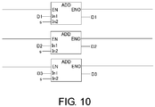
- Fig. 10 is a diagram illustrating screen display of the display device after an input candidate is selected.
- the ladder diagram program As illustrated in (A) of Fig. 9 , the ladder diagram program according to this example, two FBs with a command name ADD have already appeared. As illustrated in (B) of Fig. 9 , when the operator inputs the command name (ADD) of the FBs to be inserted into the ladder diagram program, a partial circuit which is an input candidate is displayed on the display device.
- the input variables of the partial circuit which is the input candidate are estimated to be [D3, s] since input variables of two FBs that have the command name ADD and have already appeared are [D1, s] and [D2, s].
- An output variable of the partial circuit which is the input candidate is estimated to be [D3] since the output variables of the two FBs that have the command name ADD and have already appeared are [D1] and [D2].
- the FB with the input command name is replaced with the partial circuit which is the selected input candidate.
- FIG. 11 is a diagram illustrating screen display of the display device before a command name of a ladder circuit is input.
- (B) of Fig. 11 is a diagram illustrating screen display of the display device after the command name of the ladder circuit is input.
- Fig. 12 is a diagram illustrating screen display of the display device after an input candidate is selected.
- the ladder diagram program As illustrated in (A) of Fig. 11 , the ladder diagram program according to this example, two ladder circuits with a command name EQ have already appeared. As illustrated in (B) of Fig. 11 , when the operator inputs the command name (EQ) of the ladder circuits to be inserted into the ladder diagram program, a partial circuit which is an input candidate is displayed on the display device.
- contact circuits in which three contacts a, b, and c are connected in parallel and coils connected to the contact circuits are common circuits. Accordingly, in this example, a partial circuit including the contact circuit in which three contact points a, b, and c are connected in parallel and a coil connected to the contact circuit is output as an input candidate.
- the input variables of the partial circuit which is the input candidate are estimated to be [x, Y3] since input variables of two ladder circuits that have the command name EQ and have already appeared are [x, Y1] and [x, Y2].
- a coil of the partial circuit which is the input candidate is estimated to be A3 since the coils connected to the contact circuits in which three contacts a, b, and c are connected in parallel are A1 and A2.
- the number of partial circuits outputted as input candidates is 1, but the number of partial circuits output as input candidates may be 2 or more.
- the ladder diagram program generation assistance device 1 differs from the ladder diagram program generation assistance device according to the foregoing example in that the variable setting unit 22 is not included (the other configurations are the same as the configurations of the foregoing example).
- Fig. 13 is a flowchart illustrating an operation of a ladder diagram program generation assistance device according to the example.
- the partial circuit search unit 21 searches for and extracts partial circuits (s12).
- a search range in which the partial circuit search unit 21 searches for the partial circuits is a range from the first row of the ladder diagram program 20 generated and edited at that time to a row in which the circuit elements with the presently input variable name are added, as in the foregoing example.
- the partial circuit search unit 21 searches for the circuit elements that have a variable name which is the same as the presently input variable name and that have already appeared a predetermined number of times (for example, a plurality of times such as twice or three times) or more in the search range of the ladder diagram program 20.
- a predetermined number of times for example, a plurality of times such as twice or three times
- the partial circuit search unit 21 determines that there are no partial circuits corresponding to the circuit elements with the presently input variable name.
- the partial circuit search unit 21 When the partial circuit search unit 21 can search for the circuit elements satisfying the foregoing condition and other ladder circuits connected to the circuit elements are common between the searched circuit elements, the partial circuit search unit 21 extracts a circuit formed by the searched circuit elements and the other common ladder circuits as a partial circuit. When the circuit elements satisfying the condition can be searched for and the other ladder circuits connected to the circuit elements are not common between the searched circuit elements, the partial circuit search unit 21 according to the example determines that there are no partial circuits corresponding to the circuit elements with the presently input variable name.
- the ladder diagram program generation assistance device 1 when the partial circuits may not be extracted (when it is determined that there are no partial circuits), an input of the ladder circuits or the like connected to the circuit elements with the currently input variable name is received (s3 and s17) and the process return to s11.
- the ladder diagram program generation assistance device 1 when the partial circuits can be extracted, the extracted partial circuits are outputs as input candidates (s13 and s14).
- the display unit 4 displays the input candidates on the display device.
- the operator performs an operation of selecting an input candidate in the input operation unit 3.
- the replacement processing unit 23 replaces the circuit element with the currently input variable name with the partial circuit which is the selected input candidate (s15 and s16) and the process returns to s11.
- the ladder diagram program generation assistance device 1 When the operator performs an operation related to an input of the ladder circuits or the like connected to the circuit elements with the currently input variable name without selecting the input candidate, the ladder diagram program generation assistance device 1 receives the operation by the operator (s15 and s17) and the process returns to s1. In s17, the ladder circuits or the like in response to the input operation of the operator are connected to the circuit elements with the presently input variable name.
- the ladder diagram program generation assistance device 1 when a ladder circuit formed by a plurality of circuit elements (a ladder circuit including no FBs) appears repeatedly as a partial circuit in the generated an edited ladder diagram program, the operator can perform an input operation related to the partial circuit by performing a simple operation of inputting the variable name of one circuit element belonging to the partial circuit and selecting the output input candidate (the partial circuit). Accordingly, it is possible to improve efficiency of generation and editing of the ladder diagram program in which the partial circuit formed by the plurality of circuit elements appears repeatedly.
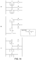
- FIG. 14 is a diagram illustrating screen display of the display device before a variable name of a circuit element of a ladder circuit is input.
- (B) of Fig. 14 is a diagram illustrating screen display of the display device after the variable name of the circuit element of the ladder circuit is input.
- (C) of Fig. 14 is a diagram illustrating screen display of the display device after an input candidate is selected.
- the number of partial circuits outputted as input candidates is not limited to 1, but two or more partial circuits may be output.
Landscapes
- Physics & Mathematics (AREA)
- General Physics & Mathematics (AREA)
- Engineering & Computer Science (AREA)
- Automation & Control Theory (AREA)
- Programmable Controllers (AREA)
Abstract
Description
- The present invention relates to a technology for assisting with generation and editing of a ladder diagram program executed by a programmable controller (PLC).
- In the related art, ladder diagram programs executed by programmable controllers (PLCs) are generated by general-purpose computers such as personal computers and are uploaded to the PLCs in many cases. In general-purpose computers, programs that perform a generation and editing function of generating and editing a ladder diagram program, an upload function of uploading the ladder diagram program to PLCs, a download function of downloading the ladder diagram program from PLCs, and the like are installed.
- As a device assisting with generation of a ladder diagram program, there is a device disclosed in, for example,
Patent Literature 1.Patent Literature 1 facilitates an input of a variable name described as an operand of a command. In particular, when a plurality of variables has variable names differentiated by suffixing numbers, signs, or the like to the same character strings, an input of variable names is facilitated. - Specifically, in
Patent Literature 1, when one character of a character string that forms a variable name is input, all the variable names whose prefix matches character strings (confirmed character strings) confirmed by then and character strings formed by the one character presently input are extracted from a variable table. InPatent Literature 1, when the number of extracted variable names is single, the variable name is confirmed as an operand. When the number of extracted variable names is plural, character strings of portions whose prefixes match all the extracted variable names are set as confirmed character strings. InPatent Literature 1, an input of one character subsequent to the confirmed character string is received again and the foregoing operation is repeated. - [Patent Literature 1] Japanese Patent Application Laid-Open No.
2010-238225 - An input of a variable name described as an operand of a command is facilitated in
Patent Literature 1. However, an improvement in efficiency of generation and editing jobs of the ladder diagram program in which the same ladder circuit or similar ladder circuits appear repeatedly is not realized. More specifically, an operator may not simply perform an operation of inputting the same ladder circuit or similar ladder circuits appearing repeatedly in the ladder diagram program which is being generated and edited. - The ladder circuits mentioned here are circuits that have a logical meaning and are function blocks (FB), contacts, or the like. The similar ladder circuits are circuits that have the same logical meaning and different input variables.
- In generation of a ladder diagram program, an operation of repeatedly inputting the same partial circuit or similar partial circuits is a monotonous and cumbersome operation for an operator and it is easy to cause an input mistake.
- An objective of the invention is to provide a technology for improving generation and editing efficiency of a ladder diagram program in which the same ladder circuit or similar ladder circuits repeatedly appear.
- A ladder diagram program generation assistance device according to the invention is configured as follows to achieve the objective of the invention.
- An input unit receives an input related to generation and editing of a ladder diagram program. A partial circuit search unit, when the input unit receives a command name of the ladder circuit to be inserted into the ladder diagram program, searches for and extracts a partial circuit corresponding to a ladder circuit with the input command name. For example, the partial circuit search unit extracts a partial circuit including a ladder circuit that has a command name which is the same as the input command name. The partial circuit mentioned here may be a single ladder circuit that has a logical meaning or may include a plurality of ladder circuits that have a logical meaning.
- An input candidate output unit outputs an input candidate corresponding to the partial circuit extracted by the partial circuit search unit. A replacement processing unit when a selection of the input candidate output by the input candidate output unit is received, replaces, with the selected input candidate, the ladder circuit of which the command name has been input by the input unit.
- Therefore, an operator can perform an operation of inputting the same ladder circuit or similar ladder circuits appearing repeatedly by performing a simple operation of inputting the command name of the ladder circuit and selecting the output input candidate in the generated and edited ladder diagram program. Accordingly, it is possible to improve efficiency of generation and editing of the ladder diagram program in which the same ladder circuit or similar ladder circuits appear repeatedly.
- The partial circuit search unit may search for a ladder circuit that has a command name which is the same as the command name input in the input unit and repeatedly appears a predetermined number of times or more in the ladder diagram program which is being generated or edited, and extracts a partial circuit in accordance with the searched ladder circuit. In this configuration, it is possible to improve precision with which the input candidate to be output is a partial circuit including a ladder circuit of which a command name is input by the operation.
- A variable setting unit that sets a variable of the partial circuit extracted by the partial circuit search unit may be included and the input candidate output unit may output the partial circuit in which the variable is set by the variable setting unit as an input candidate. For example, the variable setting unit may set the variable of the partial circuit extracted by the partial circuit search unit in accordance with the variable of the ladder circuit that has a command name which is the same as the command name input in the input unit and appears repeatedly a plurality number of times in the ladder diagram program which is being generated or edited.
- In this configuration, since labor taken to set a variable can be reduced, it is possible to further improve efficiency of generation and editing of the ladder diagram program in which the same ladder circuit or similar ladder circuits appear repeatedly.
- The partial circuit search unit may also search for and extract a partial circuit corresponding to a ladder circuit with an input variable name when the input unit receives a variable name of the ladder circuit to be inserted into the ladder diagram program. The input candidate output unit outputs an input candidate corresponding to the partial circuit extracted by the partial circuit search unit. The replacement processing unit replaces, with the selected input candidate, the ladder circuit of which the variable name has been input when a selection of the input candidate output by the input candidate output unit is received. In this configuration, it is also possible to improve efficiency of generation and editing of the ladder diagram program in which the same ladder circuit or similar ladder circuits appear repeatedly.
- According to the invention, it is possible to improve generation and editing efficiency of the ladder diagram program in which the same ladder circuit or similar ladder circuits repeatedly appear.
-
-
Fig. 1 is a block diagram illustrating a configuration of main units of a ladder diagram program generation assistance device. -
Fig. 2 is a block diagram illustrating a functional configuration of a control unit. -
Fig. 3 is a flowchart illustrating an operation of the ladder diagram program generation assistance device. -
Fig. 4 includes (A) and (B), in which (A) is a diagram illustrating screen display of a display device before a command name of an FB is input and (B) is a diagram illustrating screen display of the display device after the command name of the FB is input. -
Fig. 5 is a diagram illustrating screen display of the display device after an input candidate is selected. -
Fig. 6 is a diagram illustrating screen display of the display device before a command name of an FB is input. -
Fig. 7 is a diagram illustrating screen display of the display device after the command name of the FB is input. -
Fig. 8 is a diagram illustrating screen display of the display device after an input candidate is selected. -
Fig. 9 includes (A) and (B), in which (A) is a diagram illustrating screen display of the display device before a command name of an FB is input and (B) is a diagram illustrating screen display of the display device after the command name of the FB is input. -
Fig. 10 is a diagram illustrating screen display of the display device after an input candidate is selected. -
Fig. 11 includes (A) and (B), in which (A) is a diagram illustrating screen display of the display device before a command name of an FB is input and (B) is a diagram illustrating screen display of the display device after the command name of the FB is input. -
Fig. 12 is a diagram illustrating screen display of the display device after an input candidate is selected. -
Fig. 13 is a flowchart illustrating an operation of a ladder diagram program generation assistance device according to another example. -
Fig. 14 includes (A), (B) and (C), in which (A) is a diagram illustrating screen display of the display device before a variable name of a circuit element of a ladder circuit is input, (B) is a diagram illustrating screen display of the display device after the variable name of the circuit element of the ladder circuit is input, and (C) is a diagram illustrating screen display of the display device after an input candidate is selected. - Hereinafter, a ladder diagram program generation assistance device according to an embodiment of the invention will be described.
-
Fig. 1 is a block diagram illustrating a configuration of main units of a ladder diagram program generation assistance device according to the example. A ladder diagram programgeneration assistance device 1 according to the example includes acontrol unit 2, an input operation unit 3, adisplay unit 4, astorage unit 5, and an input andoutput unit 6. The ladder diagram programgeneration assistance device 1 can be realized by a general-purpose computer in which a program that performs a generation and editing function of generating and editing a ladder diagram program, an upload function of uploading the ladder diagram to a PLC, a download function of downloading the ladder diagram program from a PLC, and the like is installed. The computer performs a ladder diagram program generation assistance method according to the invention. A ladder diagram program generation assistance program according to the invention is installed in the computer. - The
control unit 2 controls an operation of each unit of the body of the ladder diagram programgeneration assistance device 1. - The input operation unit 3 includes an input device such as a keyboard or a mouse and receives an input in response to an operation on the input device by the operator. The input operation unit 3 is equivalent to an input unit mentioned in the invention.
- The
display unit 4 includes a display device such as a display and controls screen display in the display device. Thedisplay unit 4 causes the display to display a state or the like of the ladder diagram program generated and edited at that time or the body of the ladder diagram programgeneration assistance device 1 at that time. Thedisplay unit 4 is equivalent to an input candidate output unit mentioned in the invention. - The
storage unit 5 includes a storage medium such as a hard disk or a memory and stores a program necessary for an operation of the body of the ladder diagram programgeneration assistance device 1, data, and a ladder diagram program. - The input and
output unit 6 performs input and output of the ladder diagram program (upload or download of the ladder diagram program) to and from a programmable controller (PLC) (not illustrated). -
Fig. 2 is a block diagram illustrating a functional configuration of a control unit. Thecontrol unit 2 includes a partialcircuit search unit 21, avariable setting unit 22, and areplacement processing unit 23. Aladder diagram program 20 illustrated inFig. 2 is a program generated and edited at that time and is loaded on thecontrol unit 2. - The partial
circuit search unit 21 searches for a partial circuit corresponding to a command name of a function block (FB) for a ladder circuit input to theladder diagram program 20 processed at a time when the operator operates the input operation unit 3. The ladder circuit mentioned here is a circuit that has a logical meaning and includes not only an FB but also a circuit element such as a contact. The partial circuit mentioned here may be a single ladder circuit that has a logical meaning or may include a plurality of ladder circuits that have a logical meaning. - The partial
circuit search unit 21 searches for a partial circuit in theladder diagram program 20 processed at that time (the partialcircuit search unit 21 does not search for a partial circuit with regard to another ladder diagram program stored in thestorage unit 5 or the like). The partialcircuit search unit 21 searches for an FB that has a command name which is the same as the input command name in theladder diagram program 20 processed at that time and extracts a partial circuit including the FB. In this example, the partialcircuit search unit 21 searches for an FB that has a command name which is the same as the input command name in theladder diagram program 20 processed at that time and that has already appeared a predetermined number of times (for example, a plurality of times such as twice or three times) or more in theladder diagram program 20. - The
variable setting unit 22 sets a variable in the partial circuit extracted by the partialcircuit search unit 21. Thevariable setting unit 22 sets variables in a partial circuit presently extracted by the partialcircuit search unit 21 in accordance with variables of a plurality of partial circuits searched for by the partialcircuit search unit 21. For example, when the variables of the plurality of partial circuits searched for by the partialcircuit search unit 21 are constant, thevariable setting unit 22 sets variables with the same value. When the variables of the plurality of partial circuits searched for by the partialcircuit search unit 21 are regularly changed, thevariable setting unit 22 estimates and sets variables on the basis of this rule. When the variable is a structure, thevariable setting unit 22 sets model-matched variables which are estimated based on the variables of the plurality of partial circuits searched for by the partialcircuit search unit 21. When the variables have variable names in which signs such as numerals are suffixed to the variables, thevariable setting unit 22 estimates and sets signs of the suffixes based on the variables of the plurality of partial circuits searched for by the partialcircuit search unit 21. A partial circuit in which the variables are set by thevariable setting unit 22 is output as an input candidate. Specifically, thedisplay unit 4 displays the partial circuit in which the variables are set by thevariable setting unit 22 as an input candidate on the display device. - When the output input candidate is selected, the
replacement processing unit 23 replaces the FB to which the current command name is input in theladder diagram program 20 processed at that time with the selected input candidate (the partial circuit in which the variables are set by the variable setting unit 22). - Hereinafter, an operation of the ladder diagram program
generation assistance device 1 according to the example will be described. -
Fig. 3 is a flowchart illustrating an operation of the ladder diagram programgeneration assistance device 1 according to the example. The ladder diagram programgeneration assistance device 1 loads theladder diagram program 20 generated and edited at that time in thecontrol unit 2. The operator performs an input operation related to the generation and editing of theladder diagram program 20 in the input operation unit 3. - In the ladder diagram program
generation assistance device 1, when an input of a command name of an FB related to a ladder circuit to be inserted into theladder diagram program 20 generated and edited at that time is received (s1), the partialcircuit search unit 21 searches for and extracts partial circuits (s2). A search range in which the partialcircuit search unit 21 searches for the partial circuits is a range from the first row of theladder diagram program 20 generated and edited at that time to a row in which the FBs with the presently input command name are added. The partialcircuit search unit 21 searches for the FBs that have a command name which is the same as the presently input command name and that have already appeared repeatedly a predetermined number of times (for example, a plurality of times such as twice or three times) or more in the search range of theladder diagram program 20. When the partialcircuit search unit 21 cannot search for the FBs satisfying the foregoing condition, the partialcircuit search unit 21 determines that there are no partial circuits corresponding to the FBs with the presently input command name. - When the partial
circuit search unit 21 can search for the FBs satisfying the foregoing condition and other ladder circuits connected to the FBs are common between the searched FBs, the partialcircuit search unit 21 extracts a circuit formed by the searched FBs and the other common ladder circuits as a partial circuit. In other words, when the partialcircuit search unit 21 can search for the FBs satisfying the condition and other ladder circuits connected to the FBs are not common between the searched FBs, the partialcircuit search unit 21 extracts the searched FB as a partial circuit. - In the ladder diagram program
generation assistance device 1, when the partial circuits cannot be extracted in s2, an input of variables or the like related to the FB with the currently input command name is received (s3 and s8) and the process return to s1. - In the ladder diagram program
generation assistance device 1, when the partial circuits can be extracted in s2, thevariable setting unit 22 sets variables for the extracted partial circuits (s3 and s4). In s4, thevariable setting unit 22 sets variables of the partial circuits which are presently input candidates in accordance with the variables of the ladder circuits searched for in s2, that is, the partial circuits (the partial circuits extracted in s2) including the FBs that have the same command name and have already appeared in theladder diagram program 20 generated and edited at that time. For example, when the variables of the plurality of partial circuits searched for by the partialcircuit search unit 21 are constant, thevariable setting unit 22 sets the variables of the partial circuits which are the presently input candidates to the same value. When the variables of the plurality of partial circuits searched for by the partialcircuit search unit 21 are regularly changed, thevariable setting unit 22 estimates and sets the variables of the partial circuits which are the presently input candidates based on this rule. When the variables are structures, thevariable setting unit 22 sets the variables of the partial circuits which are the present input candidates to model-matched variables which are estimated based on the variables of the plurality of partial circuits searched for by the partialcircuit search unit 21. When the variables have variable names in which signs such as numerals are suffixed to the variables, thevariable setting unit 22 sets the variables of the partial circuits which are the present input candidates by estimating signs of the suffixes based on the variables of the plurality of partial circuits searched for by the partialcircuit search unit 21. - Accordingly, as the number of partial circuits extracted in s2 is larger, setting precision of the variables in s4 is better.
- The ladder diagram program
generation assistance device 1 outputs the partial circuits with the variables set in s4 as input candidates (s5). Thedisplay unit 4 displays the input candidates on the display device. When the input candidates displayed on the display device are desired partial circuits, the operator performs an operation of selecting an input candidate in the input operation unit 3. In the ladder diagram programgeneration assistance device 1, when the input candidate is selected, thereplacement processing unit 23 replaces the FB with the currently input command name with the partial circuit which is the selected input candidate (s6 and s7) and the process returns to s1. - When the operator performs an operation related to an input of the variables or the like to the FBs with the currently input command name without selecting the input candidate, the ladder diagram program
generation assistance device 1 receives the operation by the operator (s6 and s8) and the process returns to s1. In s8, setting of the variables or the like is performed in response to the input operation by the operator. - In this way, in the ladder diagram program
generation assistance device 1 according to the example, the operator can perform an operation of inputting the same ladder circuit (the ladder circuit including the FB) or similar ladder circuits (the ladder circuits including the FBs) appearing repeatedly by performing a simple operation of inputting the command names of the FBs and selecting the output input candidate in the generated and edited ladder diagram program. Accordingly, it is possible to improve efficiency of generation and editing of the ladder diagram program in which the same ladder circuit (the ladder circuit including the FB) or similar ladder circuits (the ladder circuits including the FBs) appear repeatedly. - Since the variables are automatically set, it is possible to further improve efficiency of generation of the ladder diagram program in which the same partial circuit (the ladder circuit including the FB) appears repeatedly.
- Hereinafter, the process illustrated in
Fig. 3 will be described more specifically exemplifying a generation and editing procedure of theladder diagram program 20. - (A) of
Fig. 4 is a diagram illustrating screen display of the display device before a command name of an FB is input. (B) ofFig. 4 is a diagram illustrating screen display of the display device after the command name of the FB is input.Fig. 5 is a diagram illustrating screen display of the display device after an input candidate is selected. - As illustrated in (A) of
Fig. 4 , in the ladder diagram program according to this example, two FBs with a command name MOVE have already appeared. As illustrated in (B) ofFig. 4 , when the operator inputs the command name (MOVE) of the FBs to be inserted into the ladder diagram program, a partial circuit which is an input candidate is displayed on the display device. The number of input variables of the partial circuit which is the input candidate is estimated to be 2 since input variables of two FBs that have the command name MOVE and have already appeared are 0 and 1. An output variable of the partial circuit which is the input candidate is estimated to be x since the output variables of the two FBs that have the command name MOVE and have already appeared are both x. - Y illustrated in (A) and (B) of
Fig. 4 , and5 indicates a coil. - Then, when the operator performs an input operation of selecting the input candidate displayed on the display device, as illustrated in
Fig. 5 , the FB with the input command name is replaced with the partial circuit which is the selected input candidate. -
Fig. 6 is a diagram illustrating screen display of the display device before a command name of an FB is input.Fig. 7 is a diagram illustrating screen display of the display device after the command name of the FB is input.Fig. 8 is a diagram illustrating screen display of the display device after an input candidate is selected. - As illustrated in
Fig. 6 , the ladder diagram program according to this example, two FBs with a command name Timer have already appeared. As illustrated inFig. 7 , when the operator inputs the command name (Timer) of the FBs to be inserted into the ladder diagram program, a partial circuit which is an input candidate is displayed on the display device. The input variables of the partial circuit which is the input candidate are estimated to be [X2, T2] since input variables of two FBs that have the command name Timer and have already appeared are [X0, T0] and [X1, T1]. An output variable of the partial circuit which is the input candidate is estimated to be [Y2, T2] since the output variables of the two FBs that have the command name Timer and have already appeared are [Y0, T0] and [Y1, T1]. - Then, when the operator performs an input operation of selecting the input candidate displayed on the display device, as illustrated in
Fig. 8 , the ladder circuit with the input command name is replaced with the partial circuit which is the selected input candidate. - A1 and A2 illustrated in
Figs. 6 ,7 , and8 indicate coils. - (A) of
Fig. 9 is a diagram illustrating screen display of the display device before a command name of an FB is input. (B) ofFig. 9 is a diagram illustrating screen display of the display device after the command name of the FB is input.Fig. 10 is a diagram illustrating screen display of the display device after an input candidate is selected. - As illustrated in (A) of
Fig. 9 , the ladder diagram program according to this example, two FBs with a command name ADD have already appeared. As illustrated in (B) ofFig. 9 , when the operator inputs the command name (ADD) of the FBs to be inserted into the ladder diagram program, a partial circuit which is an input candidate is displayed on the display device. The input variables of the partial circuit which is the input candidate are estimated to be [D3, s] since input variables of two FBs that have the command name ADD and have already appeared are [D1, s] and [D2, s]. An output variable of the partial circuit which is the input candidate is estimated to be [D3] since the output variables of the two FBs that have the command name ADD and have already appeared are [D1] and [D2]. - Then, when the operator performs an input operation of selecting the input candidate displayed on the display device, as illustrated in
Fig. 10 , the FB with the input command name is replaced with the partial circuit which is the selected input candidate. - (A) of
Fig. 11 is a diagram illustrating screen display of the display device before a command name of a ladder circuit is input. (B) ofFig. 11 is a diagram illustrating screen display of the display device after the command name of the ladder circuit is input.Fig. 12 is a diagram illustrating screen display of the display device after an input candidate is selected. - As illustrated in (A) of
Fig. 11 , the ladder diagram program according to this example, two ladder circuits with a command name EQ have already appeared. As illustrated in (B) ofFig. 11 , when the operator inputs the command name (EQ) of the ladder circuits to be inserted into the ladder diagram program, a partial circuit which is an input candidate is displayed on the display device. In this example, contact circuits in which three contacts a, b, and c are connected in parallel and coils connected to the contact circuits are common circuits. Accordingly, in this example, a partial circuit including the contact circuit in which three contact points a, b, and c are connected in parallel and a coil connected to the contact circuit is output as an input candidate. - The input variables of the partial circuit which is the input candidate are estimated to be [x, Y3] since input variables of two ladder circuits that have the command name EQ and have already appeared are [x, Y1] and [x, Y2]. A coil of the partial circuit which is the input candidate is estimated to be A3 since the coils connected to the contact circuits in which three contacts a, b, and c are connected in parallel are A1 and A2.
- Then, when the operator performs an input operation of selecting the input candidate displayed on the display device, as illustrated in
Fig. 12 , the ladder circuit with the input command name is replaced with the partial circuit which is the selected input candidate. - In the foregoing example, the number of partial circuits outputted as input candidates is 1, but the number of partial circuits output as input candidates may be 2 or more.
- Another example will be described. In the foregoing example, when the command name of the FBs is input, the FBs that have a command name which is the same as the presently input command name and that have already appeared a predetermined number of times or more in the range from the first row of the
ladder diagram program 20 generated and edited at that time to the row in which the FB with the presently input command name is added are searched for to extract the partial circuit. In the other example, when a variable name of a contact, a coil, or the like which is a circuit element of a ladder circuit is input, circuit elements that have a variable name which is the same as the presently input variable name and that have already appeared repeatedly a predetermined number of times or more in a range from the first row of theladder diagram program 20 generated and edited at that time to a row in which the circuit element with the presently input variable name is added are searched for to extract a partial circuit. The ladder diagram programgeneration assistance device 1 according to this example differs from the ladder diagram program generation assistance device according to the foregoing example in that thevariable setting unit 22 is not included (the other configurations are the same as the configurations of the foregoing example). -
Fig. 13 is a flowchart illustrating an operation of a ladder diagram program generation assistance device according to the example. In the ladder diagram programgeneration assistance device 1, when an input of a variable name of a circuit element related to a ladder circuit to be inserted into theladder diagram program 20 generated and edited at that time is received (s11), the partialcircuit search unit 21 searches for and extracts partial circuits (s12). A search range in which the partialcircuit search unit 21 searches for the partial circuits is a range from the first row of theladder diagram program 20 generated and edited at that time to a row in which the circuit elements with the presently input variable name are added, as in the foregoing example. The partialcircuit search unit 21 searches for the circuit elements that have a variable name which is the same as the presently input variable name and that have already appeared a predetermined number of times (for example, a plurality of times such as twice or three times) or more in the search range of theladder diagram program 20. When the partialcircuit search unit 21 cannot search for the circuit elements satisfying the foregoing condition, the partialcircuit search unit 21 determines that there are no partial circuits corresponding to the circuit elements with the presently input variable name. - When the partial
circuit search unit 21 can search for the circuit elements satisfying the foregoing condition and other ladder circuits connected to the circuit elements are common between the searched circuit elements, the partialcircuit search unit 21 extracts a circuit formed by the searched circuit elements and the other common ladder circuits as a partial circuit. When the circuit elements satisfying the condition can be searched for and the other ladder circuits connected to the circuit elements are not common between the searched circuit elements, the partialcircuit search unit 21 according to the example determines that there are no partial circuits corresponding to the circuit elements with the presently input variable name. - In the ladder diagram program
generation assistance device 1, when the partial circuits may not be extracted (when it is determined that there are no partial circuits), an input of the ladder circuits or the like connected to the circuit elements with the currently input variable name is received (s3 and s17) and the process return to s11. - In the ladder diagram program
generation assistance device 1, when the partial circuits can be extracted, the extracted partial circuits are outputs as input candidates (s13 and s14). Thedisplay unit 4 displays the input candidates on the display device. When the input candidates displayed on the display device are desired partial circuits, the operator performs an operation of selecting an input candidate in the input operation unit 3. In the ladder diagram programgeneration assistance device 1, when the input candidate is selected, thereplacement processing unit 23 replaces the circuit element with the currently input variable name with the partial circuit which is the selected input candidate (s15 and s16) and the process returns to s11. - When the operator performs an operation related to an input of the ladder circuits or the like connected to the circuit elements with the currently input variable name without selecting the input candidate, the ladder diagram program
generation assistance device 1 receives the operation by the operator (s15 and s17) and the process returns to s1. In s17, the ladder circuits or the like in response to the input operation of the operator are connected to the circuit elements with the presently input variable name. - In this way, in the ladder diagram program
generation assistance device 1 according to the example, when a ladder circuit formed by a plurality of circuit elements (a ladder circuit including no FBs) appears repeatedly as a partial circuit in the generated an edited ladder diagram program, the operator can perform an input operation related to the partial circuit by performing a simple operation of inputting the variable name of one circuit element belonging to the partial circuit and selecting the output input candidate (the partial circuit). Accordingly, it is possible to improve efficiency of generation and editing of the ladder diagram program in which the partial circuit formed by the plurality of circuit elements appears repeatedly. - (A) of
Fig. 14 is a diagram illustrating screen display of the display device before a variable name of a circuit element of a ladder circuit is input. (B) ofFig. 14 is a diagram illustrating screen display of the display device after the variable name of the circuit element of the ladder circuit is input. (C) ofFig. 14 is a diagram illustrating screen display of the display device after an input candidate is selected. - As illustrated in (A) of
Fig. 14 , the ladder diagram program according to this example, two ladder circuits in which two contacts a and b are connected in parallel have already appeared. As illustrated in (B) ofFig. 14 , when the operator inputs the contact a of the ladder circuit to be inserted into the ladder diagram program, a partial circuit which is an input candidate is displayed on the display device. In this example, a partial circuit in which the two contact points a and b are connected in parallel is output as an input candidate. - Then, when the operator performs an input operation of selecting the input candidate displayed on the display device, as illustrated in (C) of
Fig. 14 , the ladder circuit with the input command name is replaced with the partial circuit which is the selected input candidate. - In this example, the number of partial circuits outputted as input candidates is not limited to 1, but two or more partial circuits may be output.
-
- 1
- Ladder diagram program generation assistance device
- 2.
- Control unit
- 3
- Input operation unit
- 4
- Display unit
- 5
- Storage unit
- 6
- Input and output unit
- 20
- Ladder diagram program
- 21
- Partial circuit search unit
- 22
- Variable setting unit
- 23
- Replacement processing unit
Claims (10)
- A ladder diagram program generation assistance device comprising:an input unit, receiving an input related to generation and editing of a ladder diagram program;a partial circuit search unit, when the input unit receives a command name of the ladder circuit to be inserted into the ladder diagram program, searching for and extracting a partial circuit corresponding to a ladder circuit with the input command name;an input candidate output unit, outputting an input candidate corresponding to the partial circuit extracted by the partial circuit search unit; anda replacement processing unit, when a selection of the input candidate output by the input candidate output unit is received, replacing, with the selected input candidate, the ladder circuit of which the command name has been input by the input unit.
- The ladder diagram program generation assistance device according to claim 1, wherein the partial circuit search unit extracts a partial circuit including a ladder circuit that has a command name which is the same as the command name input in the input unit.
- The ladder diagram program generation assistance device according to claim 1 or 2, wherein the partial circuit search unit searches for a ladder circuit that has a command name which is the same as the command name input in the input unit and repeatedly appears a predetermined number of times or more in the ladder diagram program which is being generated or edited, and extracts a partial circuit in accordance with the searched ladder circuit.
- The ladder diagram program generation assistance device according to any one of claims 1 to 3, further comprising:a variable setting unit, setting a variable of the partial circuit extracted by the partial circuit search unit,wherein the input candidate output unit outputs the partial circuit in which the variable is set by the variable setting unit as the input candidate.
- The ladder diagram program generation assistance device according to claim 4, wherein the variable setting unit sets the variable of the partial circuit extracted by the partial circuit search unit in accordance with the variable of the ladder circuit that has a command name which is the same as the command name input in the input unit and appears repeatedly a plurality number of times in the ladder diagram program which is being generated or edited.
- A ladder diagram program generation assistance device comprising:an input unit, receiving an input related to generation and editing of a ladder diagram program;a partial circuit search unit, when the input unit receives a variable name of the ladder circuit to be inserted into the ladder diagram program, searching for and extracting a partial circuit corresponding to a ladder circuit with the input variable name;an input candidate output unit, outputting an input candidate corresponding to the partial circuit extracted by the partial circuit search unit; anda replacement processing unit, when a selection of the input candidate output by the input candidate output unit is received, replacing, with the selected input candidate, the ladder circuit of which the variable name has been input by the input unit.
- A ladder diagram program generation assistance method, causing a computer to perform:a partial circuit search step of when an input unit receiving an input related to generation and editing of a ladder diagram program receives a command name of the ladder circuit to be inserted into the ladder diagram program, searching for and extracting a partial circuit corresponding to a ladder circuit with the input command name;an input candidate output step of outputting an input candidate corresponding to the partial circuit extracted in the partial circuit search step; anda replacement step of when a selection of the input candidate output in the input candidate output step is received, replacing, with the selected input candidate, the ladder circuit of which the command name has been input by the input unit.
- A ladder diagram program generation assistance method, causing a computer to perform:a partial circuit search step of when an input unit receiving an input related to generation and editing of a ladder diagram program receives a variable name of the ladder circuit to be inserted into the ladder diagram program, searching for and extracting a partial circuit corresponding to a ladder circuit with the input variable name;an input candidate output step of outputting an input candidate corresponding to the partial circuit extracted in the partial circuit search step; anda replacement step of when a selection of the input candidate output in the input candidate output step is received, replacing, with the selected input candidate, the ladder circuit of which the variable name has been input by the input unit.
- A ladder diagram program generation assistance program, causing a computer to perform:a partial circuit search step of when an input unit receiving an input related to generation and editing of a ladder diagram program receives a command name of the ladder circuit to be inserted into the ladder diagram program, searching for and extracting a partial circuit corresponding to a ladder circuit with the input command name;an input candidate output step of outputting an input candidate corresponding to the partial circuit extracted in the partial circuit search step; anda replacement step of when a selection of the input candidate output in the input candidate output step is received, replacing, with the selected input candidate, the ladder circuit of which the command name has been input by the input unit.
- A ladder diagram program generation assistance program, causing a computer to perform:a partial circuit search step of when an input unit receiving an input related to generation and editing of a ladder diagram program receives a variable name of the ladder circuit to be inserted into the ladder diagram program, searching for and extracting a partial circuit corresponding to a ladder circuit with the input variable name;an input candidate output step of outputting an input candidate corresponding to the partial circuit extracted in the partial circuit search step; anda replacement step of when a selection of the input candidate output in the input candidate output step is received, replacing, with the selected input candidate, the ladder circuit of which the variable name has been input by the input unit.
Applications Claiming Priority (2)
| Application Number | Priority Date | Filing Date | Title |
|---|---|---|---|
| JP2018046575A JP6988597B2 (en) | 2018-03-14 | 2018-03-14 | Ladder diagram program creation support device, ladder diagram program creation support method, and ladder diagram program creation support program |
| PCT/JP2019/005779 WO2019176451A1 (en) | 2018-03-14 | 2019-02-18 | Ladder diagram program generation assistance device, ladder diagram program generation assistance method, and ladder diagram program generation assistance program |
Publications (3)
| Publication Number | Publication Date |
|---|---|
| EP3767412A1 true EP3767412A1 (en) | 2021-01-20 |
| EP3767412A4 EP3767412A4 (en) | 2021-12-29 |
| EP3767412B1 EP3767412B1 (en) | 2023-08-02 |
Family
ID=67906552
Family Applications (1)
| Application Number | Title | Priority Date | Filing Date |
|---|---|---|---|
| EP19768213.1A Active EP3767412B1 (en) | 2018-03-14 | 2019-02-18 | Ladder diagram program generation assistance device, ladder diagram program generation assistance method, and ladder diagram program generation assistance program |
Country Status (5)
| Country | Link |
|---|---|
| US (1) | US11378928B2 (en) |
| EP (1) | EP3767412B1 (en) |
| JP (1) | JP6988597B2 (en) |
| CN (1) | CN111033399B (en) |
| WO (1) | WO2019176451A1 (en) |
Families Citing this family (5)
| Publication number | Priority date | Publication date | Assignee | Title |
|---|---|---|---|---|
| WO2020174627A1 (en) * | 2019-02-27 | 2020-09-03 | 三菱電機株式会社 | Design assistance device, design assistance method, and design assistance program |
| JP2024011851A (en) * | 2022-07-15 | 2024-01-25 | オムロン株式会社 | Control program editing device, editing method, and program |
| JP2024011850A (en) * | 2022-07-15 | 2024-01-25 | オムロン株式会社 | Control program editing device, editing method, and program |
| JP2024011849A (en) | 2022-07-15 | 2024-01-25 | オムロン株式会社 | Ladder program editing device, editing method and editing program |
| WO2026120715A1 (en) * | 2024-12-04 | 2026-06-11 | ファナック株式会社 | Sequence program creation device |
Family Cites Families (14)
| Publication number | Priority date | Publication date | Assignee | Title |
|---|---|---|---|---|
| US4038562A (en) * | 1972-06-16 | 1977-07-26 | Cutler-Hammer, Inc. | Ladder static logic control system and method of making |
| JPS5726387B2 (en) | 1974-12-27 | 1982-06-04 | ||
| JP2003084813A (en) * | 2001-09-14 | 2003-03-19 | Fuji Electric Co Ltd | Ladder circuit editing device and its editing method |
| JP4494361B2 (en) * | 2006-03-31 | 2010-06-30 | 三菱電機株式会社 | Ladder program optimization device and optimization program |
| JP4952401B2 (en) * | 2007-06-29 | 2012-06-13 | 株式会社ジェイテクト | PLC |
| JP2009009462A (en) * | 2007-06-29 | 2009-01-15 | Fanuc Ltd | Sequence program editing apparatus |
| KR101275342B1 (en) * | 2009-02-04 | 2013-06-17 | 미쓰비시덴키 가부시키가이샤 | Ladder program edition device |
| JP5454783B2 (en) * | 2009-03-13 | 2014-03-26 | オムロン株式会社 | Variable name input support method in PLC programming, variable name input support device in PLC programming, and computer program |
| US9747529B2 (en) * | 2012-03-19 | 2017-08-29 | Mitsubishi Electric Corporation | Sequence program creation device |
| KR101711772B1 (en) * | 2012-11-22 | 2017-03-02 | 미쓰비시덴키 가부시키가이샤 | System-building assistance device |
| KR20150127161A (en) | 2013-03-07 | 2015-11-16 | 미쓰비시덴키 가부시키가이샤 | Ladder program display program and ladder program display device |
| DE112013006769T5 (en) * | 2013-03-29 | 2015-11-26 | Mitsubishi Electric Corp. | Flow program component generation program and flow program component generation device |
| JP6122054B2 (en) * | 2015-03-13 | 2017-04-26 | ファナック株式会社 | Monitor device having branch circuit extraction display function of ladder program |
| US20180095447A1 (en) * | 2016-09-30 | 2018-04-05 | Omron Corporation | Program development supporting apparatus, program development supporting method, and program development supporting program |
-
2018
- 2018-03-14 JP JP2018046575A patent/JP6988597B2/en active Active
-
2019
- 2019-02-18 US US16/639,589 patent/US11378928B2/en active Active
- 2019-02-18 EP EP19768213.1A patent/EP3767412B1/en active Active
- 2019-02-18 WO PCT/JP2019/005779 patent/WO2019176451A1/en not_active Ceased
- 2019-02-18 CN CN201980003924.8A patent/CN111033399B/en active Active
Also Published As
| Publication number | Publication date |
|---|---|
| JP2019159893A (en) | 2019-09-19 |
| CN111033399B (en) | 2023-01-24 |
| US11378928B2 (en) | 2022-07-05 |
| JP6988597B2 (en) | 2022-01-05 |
| US20200225634A1 (en) | 2020-07-16 |
| WO2019176451A1 (en) | 2019-09-19 |
| EP3767412A4 (en) | 2021-12-29 |
| CN111033399A (en) | 2020-04-17 |
| EP3767412B1 (en) | 2023-08-02 |
Similar Documents
| Publication | Publication Date | Title |
|---|---|---|
| EP3767412B1 (en) | Ladder diagram program generation assistance device, ladder diagram program generation assistance method, and ladder diagram program generation assistance program | |
| US9626160B2 (en) | Sequence-program-component creation program and sequence-program-component creation device | |
| JP7031627B2 (en) | Analytical equipment, analysis method, and analysis program | |
| JP6869453B2 (en) | Information processing equipment, information processing methods and information processing programs | |
| CN113711142B (en) | Commissioning aids, commissioning aids, recording media | |
| EP3940483A1 (en) | Graph display device, graph display method, and graph display program | |
| JPWO2016181526A1 (en) | Control logic diagram analysis apparatus and control logic diagram analysis method | |
| EP3940472B1 (en) | Ladder diagram program creation assistance device, ladder diagram program creation assistance method, and ladder diagram program creation assistance program | |
| CN109117431B (en) | Systems and methods for merging source data from a source application to target data from a target application | |
| JP2020149299A (en) | Graph display device, graph display method, and graph display program | |
| KR20010106422A (en) | Ladder circuit editing device | |
| EP4557026A1 (en) | Control program editing device, editing method, and program | |
| JP2016153930A (en) | Configuration information management device, configuration information management method and configuration information management program | |
| JP2020149298A (en) | Graph display device, graph display method, and graph display program | |
| JP7063291B2 (en) | Analytical equipment, analysis method, and analysis program | |
| CN117170711A (en) | Method, device, equipment and storage medium for updating function block parameters | |
| JP6051969B2 (en) | Hangul character input program and Hangul character input device | |
| JP4560663B2 (en) | Drawing management system | |
| JPH0440564A (en) | Hardware circuit generating device | |
| JP2016162366A (en) | Log data processing method, log data processing program, and log data processor |
Legal Events
| Date | Code | Title | Description |
|---|---|---|---|
| STAA | Information on the status of an ep patent application or granted ep patent |
Free format text: STATUS: THE INTERNATIONAL PUBLICATION HAS BEEN MADE |
|
| PUAI | Public reference made under article 153(3) epc to a published international application that has entered the european phase |
Free format text: ORIGINAL CODE: 0009012 |
|
| STAA | Information on the status of an ep patent application or granted ep patent |
Free format text: STATUS: REQUEST FOR EXAMINATION WAS MADE |
|
| 17P | Request for examination filed |
Effective date: 20200214 |
|
| AK | Designated contracting states |
Kind code of ref document: A1 Designated state(s): AL AT BE BG CH CY CZ DE DK EE ES FI FR GB GR HR HU IE IS IT LI LT LU LV MC MK MT NL NO PL PT RO RS SE SI SK SM TR |
|
| AX | Request for extension of the european patent |
Extension state: BA ME |
|
| DAV | Request for validation of the european patent (deleted) | ||
| DAX | Request for extension of the european patent (deleted) | ||
| A4 | Supplementary search report drawn up and despatched |
Effective date: 20211130 |
|
| RIC1 | Information provided on ipc code assigned before grant |
Ipc: G05B 19/05 20060101AFI20211124BHEP |
|
| GRAP | Despatch of communication of intention to grant a patent |
Free format text: ORIGINAL CODE: EPIDOSNIGR1 |
|
| STAA | Information on the status of an ep patent application or granted ep patent |
Free format text: STATUS: GRANT OF PATENT IS INTENDED |
|
| INTG | Intention to grant announced |
Effective date: 20230331 |
|
| GRAS | Grant fee paid |
Free format text: ORIGINAL CODE: EPIDOSNIGR3 |
|
| GRAA | (expected) grant |
Free format text: ORIGINAL CODE: 0009210 |
|
| STAA | Information on the status of an ep patent application or granted ep patent |
Free format text: STATUS: THE PATENT HAS BEEN GRANTED |
|
| AK | Designated contracting states |
Kind code of ref document: B1 Designated state(s): AL AT BE BG CH CY CZ DE DK EE ES FI FR GB GR HR HU IE IS IT LI LT LU LV MC MK MT NL NO PL PT RO RS SE SI SK SM TR |
|
| REG | Reference to a national code |
Ref country code: GB Ref legal event code: FG4D |
|
| REG | Reference to a national code |
Ref country code: CH Ref legal event code: EP |
|
| REG | Reference to a national code |
Ref country code: DE Ref legal event code: R096 Ref document number: 602019034106 Country of ref document: DE |
|
| REG | Reference to a national code |
Ref country code: IE Ref legal event code: FG4D |
|
| REG | Reference to a national code |
Ref country code: LT Ref legal event code: MG9D |
|
| REG | Reference to a national code |
Ref country code: NL Ref legal event code: MP Effective date: 20230802 |
|
| REG | Reference to a national code |
Ref country code: AT Ref legal event code: MK05 Ref document number: 1595491 Country of ref document: AT Kind code of ref document: T Effective date: 20230802 |
|
| PG25 | Lapsed in a contracting state [announced via postgrant information from national office to epo] |
Ref country code: GR Free format text: LAPSE BECAUSE OF FAILURE TO SUBMIT A TRANSLATION OF THE DESCRIPTION OR TO PAY THE FEE WITHIN THE PRESCRIBED TIME-LIMIT Effective date: 20231103 |
|
| PG25 | Lapsed in a contracting state [announced via postgrant information from national office to epo] |
Ref country code: IS Free format text: LAPSE BECAUSE OF FAILURE TO SUBMIT A TRANSLATION OF THE DESCRIPTION OR TO PAY THE FEE WITHIN THE PRESCRIBED TIME-LIMIT Effective date: 20231202 |
|
| PG25 | Lapsed in a contracting state [announced via postgrant information from national office to epo] |
Ref country code: SE Free format text: LAPSE BECAUSE OF FAILURE TO SUBMIT A TRANSLATION OF THE DESCRIPTION OR TO PAY THE FEE WITHIN THE PRESCRIBED TIME-LIMIT Effective date: 20230802 Ref country code: RS Free format text: LAPSE BECAUSE OF FAILURE TO SUBMIT A TRANSLATION OF THE DESCRIPTION OR TO PAY THE FEE WITHIN THE PRESCRIBED TIME-LIMIT Effective date: 20230802 Ref country code: PT Free format text: LAPSE BECAUSE OF FAILURE TO SUBMIT A TRANSLATION OF THE DESCRIPTION OR TO PAY THE FEE WITHIN THE PRESCRIBED TIME-LIMIT Effective date: 20231204 Ref country code: NO Free format text: LAPSE BECAUSE OF FAILURE TO SUBMIT A TRANSLATION OF THE DESCRIPTION OR TO PAY THE FEE WITHIN THE PRESCRIBED TIME-LIMIT Effective date: 20231102 Ref country code: NL Free format text: LAPSE BECAUSE OF FAILURE TO SUBMIT A TRANSLATION OF THE DESCRIPTION OR TO PAY THE FEE WITHIN THE PRESCRIBED TIME-LIMIT Effective date: 20230802 Ref country code: LV Free format text: LAPSE BECAUSE OF FAILURE TO SUBMIT A TRANSLATION OF THE DESCRIPTION OR TO PAY THE FEE WITHIN THE PRESCRIBED TIME-LIMIT Effective date: 20230802 Ref country code: LT Free format text: LAPSE BECAUSE OF FAILURE TO SUBMIT A TRANSLATION OF THE DESCRIPTION OR TO PAY THE FEE WITHIN THE PRESCRIBED TIME-LIMIT Effective date: 20230802 Ref country code: IS Free format text: LAPSE BECAUSE OF FAILURE TO SUBMIT A TRANSLATION OF THE DESCRIPTION OR TO PAY THE FEE WITHIN THE PRESCRIBED TIME-LIMIT Effective date: 20231202 Ref country code: HR Free format text: LAPSE BECAUSE OF FAILURE TO SUBMIT A TRANSLATION OF THE DESCRIPTION OR TO PAY THE FEE WITHIN THE PRESCRIBED TIME-LIMIT Effective date: 20230802 Ref country code: GR Free format text: LAPSE BECAUSE OF FAILURE TO SUBMIT A TRANSLATION OF THE DESCRIPTION OR TO PAY THE FEE WITHIN THE PRESCRIBED TIME-LIMIT Effective date: 20231103 Ref country code: FI Free format text: LAPSE BECAUSE OF FAILURE TO SUBMIT A TRANSLATION OF THE DESCRIPTION OR TO PAY THE FEE WITHIN THE PRESCRIBED TIME-LIMIT Effective date: 20230802 Ref country code: AT Free format text: LAPSE BECAUSE OF FAILURE TO SUBMIT A TRANSLATION OF THE DESCRIPTION OR TO PAY THE FEE WITHIN THE PRESCRIBED TIME-LIMIT Effective date: 20230802 |
|
| PG25 | Lapsed in a contracting state [announced via postgrant information from national office to epo] |
Ref country code: PL Free format text: LAPSE BECAUSE OF FAILURE TO SUBMIT A TRANSLATION OF THE DESCRIPTION OR TO PAY THE FEE WITHIN THE PRESCRIBED TIME-LIMIT Effective date: 20230802 |
|
| PG25 | Lapsed in a contracting state [announced via postgrant information from national office to epo] |
Ref country code: ES Free format text: LAPSE BECAUSE OF FAILURE TO SUBMIT A TRANSLATION OF THE DESCRIPTION OR TO PAY THE FEE WITHIN THE PRESCRIBED TIME-LIMIT Effective date: 20230802 |
|
| PG25 | Lapsed in a contracting state [announced via postgrant information from national office to epo] |
Ref country code: SM Free format text: LAPSE BECAUSE OF FAILURE TO SUBMIT A TRANSLATION OF THE DESCRIPTION OR TO PAY THE FEE WITHIN THE PRESCRIBED TIME-LIMIT Effective date: 20230802 Ref country code: RO Free format text: LAPSE BECAUSE OF FAILURE TO SUBMIT A TRANSLATION OF THE DESCRIPTION OR TO PAY THE FEE WITHIN THE PRESCRIBED TIME-LIMIT Effective date: 20230802 Ref country code: ES Free format text: LAPSE BECAUSE OF FAILURE TO SUBMIT A TRANSLATION OF THE DESCRIPTION OR TO PAY THE FEE WITHIN THE PRESCRIBED TIME-LIMIT Effective date: 20230802 Ref country code: EE Free format text: LAPSE BECAUSE OF FAILURE TO SUBMIT A TRANSLATION OF THE DESCRIPTION OR TO PAY THE FEE WITHIN THE PRESCRIBED TIME-LIMIT Effective date: 20230802 Ref country code: DK Free format text: LAPSE BECAUSE OF FAILURE TO SUBMIT A TRANSLATION OF THE DESCRIPTION OR TO PAY THE FEE WITHIN THE PRESCRIBED TIME-LIMIT Effective date: 20230802 Ref country code: CZ Free format text: LAPSE BECAUSE OF FAILURE TO SUBMIT A TRANSLATION OF THE DESCRIPTION OR TO PAY THE FEE WITHIN THE PRESCRIBED TIME-LIMIT Effective date: 20230802 Ref country code: SK Free format text: LAPSE BECAUSE OF FAILURE TO SUBMIT A TRANSLATION OF THE DESCRIPTION OR TO PAY THE FEE WITHIN THE PRESCRIBED TIME-LIMIT Effective date: 20230802 |
|
| REG | Reference to a national code |
Ref country code: DE Ref legal event code: R097 Ref document number: 602019034106 Country of ref document: DE |
|
| PG25 | Lapsed in a contracting state [announced via postgrant information from national office to epo] |
Ref country code: IT Free format text: LAPSE BECAUSE OF FAILURE TO SUBMIT A TRANSLATION OF THE DESCRIPTION OR TO PAY THE FEE WITHIN THE PRESCRIBED TIME-LIMIT Effective date: 20230802 |
|
| PLBE | No opposition filed within time limit |
Free format text: ORIGINAL CODE: 0009261 |
|
| STAA | Information on the status of an ep patent application or granted ep patent |
Free format text: STATUS: NO OPPOSITION FILED WITHIN TIME LIMIT |
|
| 26N | No opposition filed |
Effective date: 20240503 |
|
| PG25 | Lapsed in a contracting state [announced via postgrant information from national office to epo] |
Ref country code: SI Free format text: LAPSE BECAUSE OF FAILURE TO SUBMIT A TRANSLATION OF THE DESCRIPTION OR TO PAY THE FEE WITHIN THE PRESCRIBED TIME-LIMIT Effective date: 20230802 |
|
| PG25 | Lapsed in a contracting state [announced via postgrant information from national office to epo] |
Ref country code: MC Free format text: LAPSE BECAUSE OF FAILURE TO SUBMIT A TRANSLATION OF THE DESCRIPTION OR TO PAY THE FEE WITHIN THE PRESCRIBED TIME-LIMIT Effective date: 20230802 |
|
| REG | Reference to a national code |
Ref country code: CH Ref legal event code: PL |
|
| PG25 | Lapsed in a contracting state [announced via postgrant information from national office to epo] |
Ref country code: LU Free format text: LAPSE BECAUSE OF NON-PAYMENT OF DUE FEES Effective date: 20240218 |
|
| PG25 | Lapsed in a contracting state [announced via postgrant information from national office to epo] |
Ref country code: CH Free format text: LAPSE BECAUSE OF NON-PAYMENT OF DUE FEES Effective date: 20240229 |
|
| GBPC | Gb: european patent ceased through non-payment of renewal fee |
Effective date: 20240218 |
|
| PG25 | Lapsed in a contracting state [announced via postgrant information from national office to epo] |
Ref country code: LU Free format text: LAPSE BECAUSE OF NON-PAYMENT OF DUE FEES Effective date: 20240218 Ref country code: CH Free format text: LAPSE BECAUSE OF NON-PAYMENT OF DUE FEES Effective date: 20240229 |
|
| PG25 | Lapsed in a contracting state [announced via postgrant information from national office to epo] |
Ref country code: BG Free format text: LAPSE BECAUSE OF FAILURE TO SUBMIT A TRANSLATION OF THE DESCRIPTION OR TO PAY THE FEE WITHIN THE PRESCRIBED TIME-LIMIT Effective date: 20230802 |
|
| PG25 | Lapsed in a contracting state [announced via postgrant information from national office to epo] |
Ref country code: BG Free format text: LAPSE BECAUSE OF FAILURE TO SUBMIT A TRANSLATION OF THE DESCRIPTION OR TO PAY THE FEE WITHIN THE PRESCRIBED TIME-LIMIT Effective date: 20230802 |
|
| REG | Reference to a national code |
Ref country code: BE Ref legal event code: MM Effective date: 20240229 |
|
| PG25 | Lapsed in a contracting state [announced via postgrant information from national office to epo] |
Ref country code: BE Free format text: LAPSE BECAUSE OF NON-PAYMENT OF DUE FEES Effective date: 20240229 |
|
| PG25 | Lapsed in a contracting state [announced via postgrant information from national office to epo] |
Ref country code: GB Free format text: LAPSE BECAUSE OF NON-PAYMENT OF DUE FEES Effective date: 20240218 |
|
| PG25 | Lapsed in a contracting state [announced via postgrant information from national office to epo] |
Ref country code: FR Free format text: LAPSE BECAUSE OF NON-PAYMENT OF DUE FEES Effective date: 20240229 |
|
| PG25 | Lapsed in a contracting state [announced via postgrant information from national office to epo] |
Ref country code: IE Free format text: LAPSE BECAUSE OF NON-PAYMENT OF DUE FEES Effective date: 20240218 |
|
| PG25 | Lapsed in a contracting state [announced via postgrant information from national office to epo] |
Ref country code: IE Free format text: LAPSE BECAUSE OF NON-PAYMENT OF DUE FEES Effective date: 20240218 Ref country code: GB Free format text: LAPSE BECAUSE OF NON-PAYMENT OF DUE FEES Effective date: 20240218 Ref country code: FR Free format text: LAPSE BECAUSE OF NON-PAYMENT OF DUE FEES Effective date: 20240229 Ref country code: BE Free format text: LAPSE BECAUSE OF NON-PAYMENT OF DUE FEES Effective date: 20240229 |
|
| PG25 | Lapsed in a contracting state [announced via postgrant information from national office to epo] |
Ref country code: CY Free format text: LAPSE BECAUSE OF FAILURE TO SUBMIT A TRANSLATION OF THE DESCRIPTION OR TO PAY THE FEE WITHIN THE PRESCRIBED TIME-LIMIT; INVALID AB INITIO Effective date: 20190218 |
|
| PG25 | Lapsed in a contracting state [announced via postgrant information from national office to epo] |
Ref country code: HU Free format text: LAPSE BECAUSE OF FAILURE TO SUBMIT A TRANSLATION OF THE DESCRIPTION OR TO PAY THE FEE WITHIN THE PRESCRIBED TIME-LIMIT; INVALID AB INITIO Effective date: 20190218 |
|
| PG25 | Lapsed in a contracting state [announced via postgrant information from national office to epo] |
Ref country code: TR Free format text: LAPSE BECAUSE OF FAILURE TO SUBMIT A TRANSLATION OF THE DESCRIPTION OR TO PAY THE FEE WITHIN THE PRESCRIBED TIME-LIMIT Effective date: 20230802 |
|
| PGFP | Annual fee paid to national office [announced via postgrant information from national office to epo] |
Ref country code: DE Payment date: 20260217 Year of fee payment: 8 |