EP3767340A1 - Laser radar device, wind power generator, and wind measurement method - Google Patents
Laser radar device, wind power generator, and wind measurement method Download PDFInfo
- Publication number
- EP3767340A1 EP3767340A1 EP18916872.7A EP18916872A EP3767340A1 EP 3767340 A1 EP3767340 A1 EP 3767340A1 EP 18916872 A EP18916872 A EP 18916872A EP 3767340 A1 EP3767340 A1 EP 3767340A1
- Authority
- EP
- European Patent Office
- Prior art keywords
- laser beam
- radar device
- trajectory
- laser
- reception
- Prior art date
- Legal status (The legal status is an assumption and is not a legal conclusion. Google has not performed a legal analysis and makes no representation as to the accuracy of the status listed.)
- Granted
Links
Images




Classifications
-
- G—PHYSICS
- G01—MEASURING; TESTING
- G01P—MEASURING LINEAR OR ANGULAR SPEED, ACCELERATION, DECELERATION, OR SHOCK; INDICATING PRESENCE, ABSENCE, OR DIRECTION, OF MOVEMENT
- G01P5/00—Measuring speed of fluids, e.g. of air stream; Measuring speed of bodies relative to fluids, e.g. of ship, of aircraft
- G01P5/26—Measuring speed of fluids, e.g. of air stream; Measuring speed of bodies relative to fluids, e.g. of ship, of aircraft by measuring the direct influence of the streaming fluid on the properties of a detecting optical wave
-
- G—PHYSICS
- G01—MEASURING; TESTING
- G01S—RADIO DIRECTION-FINDING; RADIO NAVIGATION; DETERMINING DISTANCE OR VELOCITY BY USE OF RADIO WAVES; LOCATING OR PRESENCE-DETECTING BY USE OF THE REFLECTION OR RERADIATION OF RADIO WAVES; ANALOGOUS ARRANGEMENTS USING OTHER WAVES
- G01S17/00—Systems using the reflection or reradiation of electromagnetic waves other than radio waves, e.g. lidar systems
- G01S17/02—Systems using the reflection of electromagnetic waves other than radio waves
- G01S17/50—Systems of measurement based on relative movement of target
- G01S17/58—Velocity or trajectory determination systems; Sense-of-movement determination systems
-
- F—MECHANICAL ENGINEERING; LIGHTING; HEATING; WEAPONS; BLASTING
- F03—MACHINES OR ENGINES FOR LIQUIDS; WIND, SPRING, OR WEIGHT MOTORS; PRODUCING MECHANICAL POWER OR A REACTIVE PROPULSIVE THRUST, NOT OTHERWISE PROVIDED FOR
- F03D—WIND MOTORS
- F03D17/00—Monitoring or testing of wind motors, e.g. diagnostics
-
- F—MECHANICAL ENGINEERING; LIGHTING; HEATING; WEAPONS; BLASTING
- F03—MACHINES OR ENGINES FOR LIQUIDS; WIND, SPRING, OR WEIGHT MOTORS; PRODUCING MECHANICAL POWER OR A REACTIVE PROPULSIVE THRUST, NOT OTHERWISE PROVIDED FOR
- F03D—WIND MOTORS
- F03D80/00—Details, components or accessories not provided for in groups F03D1/00 - F03D17/00
-
- G—PHYSICS
- G01—MEASURING; TESTING
- G01S—RADIO DIRECTION-FINDING; RADIO NAVIGATION; DETERMINING DISTANCE OR VELOCITY BY USE OF RADIO WAVES; LOCATING OR PRESENCE-DETECTING BY USE OF THE REFLECTION OR RERADIATION OF RADIO WAVES; ANALOGOUS ARRANGEMENTS USING OTHER WAVES
- G01S17/00—Systems using the reflection or reradiation of electromagnetic waves other than radio waves, e.g. lidar systems
- G01S17/88—Lidar systems specially adapted for specific applications
- G01S17/95—Lidar systems specially adapted for specific applications for meteorological use
-
- G—PHYSICS
- G01—MEASURING; TESTING
- G01S—RADIO DIRECTION-FINDING; RADIO NAVIGATION; DETERMINING DISTANCE OR VELOCITY BY USE OF RADIO WAVES; LOCATING OR PRESENCE-DETECTING BY USE OF THE REFLECTION OR RERADIATION OF RADIO WAVES; ANALOGOUS ARRANGEMENTS USING OTHER WAVES
- G01S7/00—Details of systems according to groups G01S13/00, G01S15/00, G01S17/00
- G01S7/48—Details of systems according to groups G01S13/00, G01S15/00, G01S17/00 of systems according to group G01S17/00
- G01S7/483—Details of pulse systems
- G01S7/486—Receivers
- G01S7/487—Extracting wanted echo signals, e.g. pulse detection
-
- F—MECHANICAL ENGINEERING; LIGHTING; HEATING; WEAPONS; BLASTING
- F05—INDEXING SCHEMES RELATING TO ENGINES OR PUMPS IN VARIOUS SUBCLASSES OF CLASSES F01-F04
- F05B—INDEXING SCHEME RELATING TO WIND, SPRING, WEIGHT, INERTIA OR LIKE MOTORS, TO MACHINES OR ENGINES FOR LIQUIDS COVERED BY SUBCLASSES F03B, F03D AND F03G
- F05B2270/00—Control
- F05B2270/80—Devices generating input signals, e.g. transducers, sensors, cameras or strain gauges
- F05B2270/804—Optical devices
- F05B2270/8042—Lidar systems
-
- Y—GENERAL TAGGING OF NEW TECHNOLOGICAL DEVELOPMENTS; GENERAL TAGGING OF CROSS-SECTIONAL TECHNOLOGIES SPANNING OVER SEVERAL SECTIONS OF THE IPC; TECHNICAL SUBJECTS COVERED BY FORMER USPC CROSS-REFERENCE ART COLLECTIONS [XRACs] AND DIGESTS
- Y02—TECHNOLOGIES OR APPLICATIONS FOR MITIGATION OR ADAPTATION AGAINST CLIMATE CHANGE
- Y02A—TECHNOLOGIES FOR ADAPTATION TO CLIMATE CHANGE
- Y02A90/00—Technologies having an indirect contribution to adaptation to climate change
- Y02A90/10—Information and communication technologies [ICT] supporting adaptation to climate change, e.g. for weather forecasting or climate simulation
-
- Y—GENERAL TAGGING OF NEW TECHNOLOGICAL DEVELOPMENTS; GENERAL TAGGING OF CROSS-SECTIONAL TECHNOLOGIES SPANNING OVER SEVERAL SECTIONS OF THE IPC; TECHNICAL SUBJECTS COVERED BY FORMER USPC CROSS-REFERENCE ART COLLECTIONS [XRACs] AND DIGESTS
- Y02—TECHNOLOGIES OR APPLICATIONS FOR MITIGATION OR ADAPTATION AGAINST CLIMATE CHANGE
- Y02E—REDUCTION OF GREENHOUSE GAS [GHG] EMISSIONS, RELATED TO ENERGY GENERATION, TRANSMISSION OR DISTRIBUTION
- Y02E10/00—Energy generation through renewable energy sources
- Y02E10/70—Wind energy
- Y02E10/72—Wind turbines with rotation axis in wind direction
Definitions
- the present disclosure relates to a laser radar device for performing wind measurement.
- Non-Patent Literature 1 a technique of measuring a wind speed in front of a wind turbine for a wind power generator using a laser radar device installed on a spinner portion of the wind turbine.
- the laser radar device transmits laser light ahead of the wind turbine, receives scattered light scattered by aerosols in the atmosphere, and measures a wind speed using a reception signal of the scattered light.
- the aerosols are pieces of dust or extremely small floating particles in the atmosphere.
- Non-Patent Literature 1 T. Mikkelsen et al., "A spinner-integrated wind lidar for enhanced wind turbine control," Wind Energy, 16, pp. 625-643, 2013 .
- a conventional laser radar device emits laser light in an oblique direction with respect to the rotating shaft of a wind turbine in order to perform wind measurement in a plurality of directions. Therefore, a laser beam draws a circular trajectory in front of the wind turbine with rotation of a spinner portion. Meanwhile, since the amount of scattered light to be received is extremely small, the laser radar device obtains a signal-to-noise ratio required for wind speed measurement by integrating reception spectra calculated from reception signals of scattered light within a measurement time.
- due to a distribution of wind speed in an altitude direction when a laser beam moves during a measurement time and the altitude of a measurement position changes, different pieces of wind speed information at different altitudes are mixed, and an error in wind speed measurement becomes larger disadvantageously.
- the present invention is made to solve the above problem, and an object of the present disclosure is to obtain a laser radar device capable of measuring a wind speed with high accuracy.
- a laser radar device is installed in a spinner portion of a wind turbine, transmits laser light ahead of the wind turbine, receives scattered light of the laser light scattered at a transmission destination, and includes a trajectory section determining unit, an analyzing and integrating unit, a storing and integrating unit, and a wind speed calculating unit.
- the trajectory section determining unit determines a divided section in which a laser beam is present among a plurality of divided sections obtained by dividing a trajectory drawn by a laser beam of laser light in front of the wind turbine.
- the analyzing and integrating unit Per each divided section in which the trajectory section determining unit has determined that the laser beam is present, the analyzing and integrating unit analyzes reception signals of the scattered light to calculate reception spectra for each distance in a line-of-sight direction of the laser beam, and integrates the calculated reception spectra.
- the storing and integrating unit stores the reception spectrum calculated for each divided section by the analyzing and integrating unit.
- the wind speed calculating unit calculates a wind speed for each divided section using the reception spectrum for each divided section input from the storing and integrating unit.
- a laser radar device calculates a wind speed for each of a plurality of divided sections obtained by dividing a trajectory drawn by a laser beam in front of a wind turbine, and therefore can measure the wind speed with high accuracy.
- FIG. 1 is a schematic view illustrating a configuration of a wind power generator 1 according to a first embodiment of the present disclosure.
- the wind power generator 1 includes a wind turbine 2.
- a laser radar device 3 according to the first embodiment is installed on a spinner portion 4 of the wind turbine 2.
- the spinner portion 4 rotates together with the blade 5.
- a rotating shaft of the blade 5 is connected to a rotating shaft of a generator 7 installed on a nacelle portion 6, and when the blade 5 rotates, the rotating shaft of the generator 7 rotates in response to the rotation of the blade 5, and rotating power is converted into electric power.
- Laser light emitted from the laser radar device 3 is transmitted to the atmosphere through a window 4a provided at an end of the spinner portion 4. This laser light is scattered by aerosols in the atmosphere at a transmission destination, and the scattered light is received by the laser radar device 3. Since the aerosols are regarded as floating particles that move at the same speed as the wind, a wind speed at a position where the aerosols are present can be measured by detecting moving states of the aerosols.
- the laser radar device 3 transmits laser light in an oblique direction with respect to a rotating shaft direction of the wind turbine 2 and receives scattered light of the laser light. Since the laser radar device 3 rotates with rotation of the spinner portion 4, conical scanning is performed with a laser beam A of the laser light, and the laser beam A draws a circular trajectory B in front of the wind turbine 2 as illustrated in FIG. 1 .
- the trajectory B is defined for each distance in a line-of-sight direction of the laser beam A.
- the size of the trajectory B can be changed by changing a focusing distance (measurement distance) of the laser beam A.
- the size of the trajectory B is large.
- a wind speed at a measurement position with the highest altitude may be significantly different from that at a measurement position with the lowest altitude.
- the laser radar device 3 by calculating a wind speed for each of a plurality of divided sections obtained by dividing a trajectory drawn by the laser beam A in front of the wind turbine 2, a difference depending on the altitude of a measurement position is decreased, and wind speed measurement with high accuracy is implemented.
- FIG. 2 is a block diagram illustrating a configuration of the laser radar device 3 according to the first embodiment.
- the laser radar device 3 is installed on the spinner portion 4 of the wind turbine 2, transmits laser light in an oblique direction with respect to a rotating shaft direction of the wind turbine 2 while rotating together with the spinner portion 4, and receives scattered light of the laser light.
- the laser radar device 3 includes a light source 8, a splitter 9, a pulse modulator 10, an optical amplifier 11, a circulator 12, an optical system 13, a coupler 14, an optical receiver 15, and a signal processing unit 16.
- the principle of wind measurement by the laser radar device 3 illustrated in FIG. 2 is a so-called coherent method.
- the laser radar device 3 according to the first embodiment may perform wind measurement according to an existing principle other than the coherent method.
- the laser radar device 3 is a pulse type laser, but may be a continuous wave (CW) type laser.
- Laser light output from the light source 8 is distributed to the pulse modulator 10 and the coupler 14 by the splitter 9.
- Laser light distributed to the pulse modulator 10 is transmission light, and laser light distributed to the coupler 14 is local light.
- the pulse modulator 10 pulse-modulates the transmission light and sends the pulse-modulated transmission light to the optical amplifier 11.
- the transmission light amplified by the optical amplifier 11 is sent to the optical system 13 via the circulator 12.
- the optical system 13 transmits the transmission light to the atmosphere through the window 4a of the spinner portion 4.
- the transmission light hits aerosols in the atmosphere, is scattered, and returns to the optical system 13 as scattered light. Since the aerosols ride on the wind and move at the same speed as the wind, the frequency of the scattered light has a Doppler frequency shift depending on a wind speed.
- the scattered light received by the optical system 13 is sent to the coupler 14 as reception light by the circulator 12.
- the coupler 14 combines the reception light with the local light and sends the combined light to the optical receiver 15.
- the optical receiver 15 coherently detects the light input from the circulator 12.
- the detected signal is sent to the signal processing unit 16 as a reception signal by the optical receiver 15.
- the signal processing unit 16 analyzes the reception signal input from the optical receiver 15, calculates a reception spectrum for each distance in a line-of-sight direction of the laser beam A, and calculates a wind speed using the calculated reception spectrum.
- the signal processing unit 16 includes a trajectory section determining unit 16a, an analyzing and integrating unit 16b, a storing and integrating unit 16c, and a wind speed calculating unit 16d as functional configuration units.
- the trajectory section determining unit 16a determines a divided section in which the laser beam A is present among a plurality of divided sections obtained by dividing the trajectory B drawn in front of the wind turbine 2 by the laser beam A.
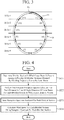
- FIG. 3 is a diagram illustrating the trajectory B of the laser beam A.
- the circular trajectory B is drawn by the laser beam A in front of the wind turbine 2 as illustrated in FIG. 3 . Since the trajectory B is uniquely determined by a laser light transmission direction and a measurement distance for which wind measurement is performed, the laser radar device 3 according to the first embodiment divides the trajectory B into a plurality of divided sections (1) to (12) and measures a wind speed for each divided section.
- a section in which a wind speed can be regarded to be uniform in a space corresponding to the section is set as a divided section.
- the divided sections (1) and (12) are associated with an altitude section A(1).
- the divided sections (2) and (11) are associated with an altitude section A(2), the divided sections (3) and (10) are associated with an altitude section A(1), and the divided sections (4) and (9) are associated with an altitude section A(4).
- the divided sections (5) and (8) are associated with an altitude section A(5), and the divided sections (6) and (7) are associated with an altitude section A(6).
- the analyzing and integrating unit 16b Per each divided section in which the trajectory section determining unit 16a has determined that the laser beam A is present, the analyzing and integrating unit 16b analyzes reception signals input from the optical receiver 15 to calculate reception spectra for each distance in a line-of-sight direction of the laser beam A, and integrates the calculated reception spectra. For example, the analyzing and integrating unit 16b continues integration of reception spectra until the laser beam A moves from a divided section in which the trajectory section determining unit 16a has determined that the laser beam A is present to a next divided section. This integration process improves a signal-to-noise ratio (hereinafter, referred to as SN ratio) of the reception spectrum.
- the SN ratio of a reception spectrum is, for example, a reception SN ratio determined from a peak intensity of the reception spectrum.
- the storing and integrating unit 16c stores a reception spectrum calculated by the analyzing and integrating unit 16b for each divided section.
- the SN ratio of the reception spectrum is improved so as to be larger than a threshold.
- the threshold is a threshold related to a reception SN ratio, an SN ratio larger than the threshold is an acceptable SN ratio, and an SN ratio equal to or smaller than the threshold is an unacceptable SN ratio.
- the wind speed calculating unit 16d calculates a wind speed for each divided section using a reception spectrum for each divided section input from the storing and integrating unit 16c. For example, the wind speed calculating unit 16d individually calculates a wind speed for each of the divided sections (1) to (12) illustrated in FIG. 3 .
- FIG. 4 is a flowchart illustrating a wind measurement method according to the first embodiment, and illustrates operations of the signal processing unit 16 in FIG. 2 .
- the trajectory section determining unit 16a determines a divided section in which the laser beam A is present among the plurality of divided sections (1) to (12) obtained by dividing the trajectory B drawn by the laser beam A (step ST1). For example, when rotation angle information indicating a current rotation angle of the wind turbine 2 is input from the wind turbine 2, the trajectory section determining unit 16a determines whether the laser beam A is present in any one of the divided sections by comparing a section of the rotation angle of the wind turbine 2 for each divided section with the rotation angle indicated by the rotation angle information.
- a section of the rotation angle of the wind turbine 2 ( ⁇ 0 to ⁇ 1) is set from a measurement start point P0 to a measurement end point P1 in the divided section (1), and the rotation angle of the wind turbine 2 is set from a measurement start point to a measurement end point also in each of the divided sections (2) to (12).
- the trajectory section determining unit 16a determines that the laser beam A is moving in the divided section (1) with the trajectory indicated by the thick arrow in FIG. 3 , and determines that the laser beam A is present in the divided section (1).
- the determination result of the trajectory section determining unit 16a is immediately sent to the analyzing and integrating unit 16b.
- the analyzing and integrating unit 16b calculates and integrates reception spectra for each divided section in which the trajectory section determining unit 16a has determined that the laser beam A is present (step ST2). For example, the analyzing and integrating unit 16b analyzes reception signals input from the optical receiver 15 and integrates reception spectra calculated for each distance in a line-of-sight direction of the laser beam A.
- the analyzing and integrating unit 16b continues integration of reception spectra while the trajectory section determining unit 16a determines that the laser beam A is present in the same divided section.
- the analyzing and integrating unit 16b stops integration of reception spectra associated with the divided section (1), and outputs information regarding the reception spectrum to the storing and integrating unit 16c.
- the storing and integrating unit 16c stores the information indicating the reception spectrum input from the analyzing and integrating unit 16b (step ST3). Since the analyzing and integrating unit 16b outputs the information regarding the reception spectrum calculated for each divided section to the storing and integrating unit 16c, the storing and integrating unit 16c stores the information regarding the reception spectrum for each divided section.
- the wind speed calculating unit 16d calculates a wind speed for each divided section using the reception spectrum for each divided section input from the storing and integrating unit 16c (step ST4). For example, since a peak frequency of the reception spectrum corresponds to a Doppler frequency shift, the wind speed calculating unit 16d calculates a wind speed value in a line-of-sight direction of the laser beam A on the basis of a peak frequency detected from the reception spectrum. The wind speed calculating unit 16d calculates a wind speed value for each divided section. A wind speed measurement result is output from the wind speed calculating unit 16d to an external device. An example of the external device is the wind power generator 1. The wind power generator 1 controls the wind turbine 2 on the basis of the wind speed measurement result input from the laser radar device 3 in such a manner that a power generation amount is improved.
- the wind speed calculating unit 16d may calculate a wind speed corresponding to an altitude section by statistically processing wind speed values obtained for divided sections associate with the same altitude section. For example, in FIG. 3 , the divided section (1) and the divided section (12) are associated with the same altitude section A(1).
- the wind speed calculating unit 16d may output an average value of a wind speed v1' obtained in the divided section (1) and a wind speed v1" obtained in the divided section (12) as a wind speed v1 in the altitude section A(1).
- the laser radar device 3 includes processing circuitry for executing processes in steps ST1 to ST4 in FIG. 4 .
- This processing circuitry may be dedicated hardware or a central processing unit (CPU) for executing a program stored in a memory.
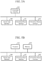
- FIG. 5A is a block diagram illustrating a hardware configuration that implements the functions of the signal processing unit 16 included in the laser radar device 3.
- FIG. 5B is a block diagram illustrating a hardware configuration that executes software for implementing the functions of the signal processing unit 16 included in the laser radar device 3.
- a signal input interface 100 relays the reception signals input from the optical receiver 15 to the signal processing unit 16.
- the analyzing and integrating unit 16b receives the reception signals from the optical receiver 15 via the signal input interface 100.
- An information input interface 101 relays rotation angle information input from the wind turbine 2 to the signal processing unit 16.
- the trajectory section determining unit 16a receives the rotation angle information from the wind turbine 2 via the information input interface 101.
- An information output interface 102 relays a wind speed measurement result output from the signal processing unit 16 to an external device.
- the wind speed calculating unit 16d outputs the wind speed measurement result to the external device via the information output interface 102.
- the external device may be the wind power generator 1 as described above.
- the processing circuitry is processing circuitry 103 of dedicated hardware illustrated in FIG. 5A
- the processing circuitry 103 is, for example, a single circuit, a composite circuit, a programmed processor, a parallel programmed processor, an application specific integrated circuit (ASIC), a field-programmable gate array (FPGA), or a combination thereof.
- the functions of the trajectory section determining unit 16a, the analyzing and integrating unit 16b, the storing and integrating unit 16c, and the wind speed calculating unit 16d may be implemented by separate processing circuits, or these functions may be implemented collectively by one processing circuit.
- the processing circuitry includes a processor 104 illustrated in FIG. 5B
- the functions of the trajectory section determining unit 16a, the analyzing and integrating unit 16b, the storing and integrating unit 16c, and the wind speed calculating unit 16d are implemented by software, firmware, or a combination of software and firmware.
- the software or the firmware is described as a program and stored in a memory 105.
- the processor 104 implements the functions of the trajectory section determining unit 16a, the analyzing and integrating unit 16b, the storing and integrating unit 16c, and the wind speed calculating unit 16d by reading and executing a program stored in the memory 105. That is, the signal processing unit 16 includes the memory 105 for storing a program that causes processes in steps ST1 to ST4 illustrated in FIG. 4 to be executed as a result when the program is executed by the processor 104. These programs cause a computer to execute the procedures or methods of the trajectory section determining unit 16a, the analyzing and integrating unit 16b, the storing and integrating unit 16c, and the wind speed calculating unit 16d.
- the memory 105 may be a computer-readable storage medium storing a program that causes a computer to function as the trajectory section determining unit 16a, the analyzing and integrating unit 16b, the storing and integrating unit 16c, and the wind speed calculating unit 16d.
- the memory 105 is, for example, a nonvolatile or volatile semiconductor memory such as a random access memory (RAM), a read only memory (ROM), a flash memory, an erasable programmable read only memory (EPROM), or an electrically-EPROM (EEPROM), a magnetic disk, a flexible disk, an optical disc, a compact disc, a mini disc, a DVD, or the like.
- RAM random access memory
- ROM read only memory
- EPROM erasable programmable read only memory
- EEPROM electrically-EPROM
- the functions of the trajectory section determining unit 16a, the analyzing and integrating unit 16b, the storing and integrating unit 16c, and the wind speed calculating unit 16d may be partially implemented by dedicated hardware and partially implemented by software or firmware.
- the function of the trajectory section determining unit 16a is implemented by a processing circuit that is dedicated hardware and the functions of the analyzing and integrating unit 16b, the storing and integrating unit 16c, and the wind speed calculating unit 16d are implemented by reading and executing a program stored in the memory 105 by the processor 104.
- the processing circuit can implement the above functions by hardware, software, firmware, or a combination thereof.
- the laser radar device 3 may include a beam scanner.
- FIG. 6 is a schematic view illustrating the laser radar device 3 including a beam scanner 17. As illustrated in FIG. 6 , the beam scanner 17 is arranged inside the spinner portion 4 on the laser light emission end of the laser radar device 3 and performs scanning with a laser beam emitted from the laser radar device 3.
- the beam scanner 17 spontaneously performs scanning with the laser beam A in such a manner that the laser beam A draws the trajectory B illustrated in FIG. 3 .
- the laser radar device 3 can measure wind speeds in all the divided sections in a shorter time.
- the type of the beam scanner 17 may be any type that can perform scanning with the laser beam A in such a manner that the laser beam A draws the trajectory B, and may be, for example, a wedge scanner type, a switch type, or a mirror type.
- the trajectory section determining unit 16a may determine a divided section in which the laser beam A is present on the basis of the rotation angle information and the rotation speed information input from the wind turbine 2.
- the trajectory section determining unit 16a calculates time required for movement of the laser beam A from a measurement start point to a measurement end point in a divided section on the basis of the rotation angle information and the rotation speed information of the wind turbine 2 at the measurement start point in the divided section.
- the time calculated in this way is integration time (measurement time) for the analyzing and integrating unit 16b to integrate reception spectra in the above divided section.
- the trajectory section determining unit 16a can appropriately determine a divided section in which the laser beam A is present on the basis of the above integration time.
- the trajectory B may be divided by the number of divisions for each distance in a line-of-sight direction of the laser beam A.
- the laser radar device 3 for outputting laser light in a pulse system can measure a wind speed at a plurality of distances in the line-of-sight direction of the laser beam A.
- a distance in the line-of-sight direction of the laser beam A (measurement distance) is short, the size of the trajectory B drawn by the laser beam A is small, and when the distance in the line-of-sight direction of the laser beam A is long, the size of the trajectory B drawn by the laser beam A is large.
- Minimizing the number of divisions of the trajectory B means maximizing the wind speed measurement time for each divided section while the laser beam A makes one round around the trajectory B. As a result, a possibility that the wind speed measurement for a plurality of rounds will be avoided is increased, and a real-time property of the wind measurement is improved.
- the laser radar device 3 includes the trajectory section determining unit 16a, the analyzing and integrating unit 16b, the storing and integrating unit 16c, and the wind speed calculating unit 16d. By including these components, the laser radar device 3 calculates a wind speed for each of a plurality of divided sections obtained by dividing the trajectory B drawn by the laser beam A in front of the wind turbine 2, and therefore can measure the wind speed with high accuracy.
- the wind power generator 1 includes the laser radar device 3, and therefore can measure a wind speed with high accuracy.
- the wind measurement method according to the first embodiment calculates a wind speed for each of a plurality of divided sections obtained by dividing the trajectory B drawn by the laser beam A, and therefore can measure the wind speed with high accuracy.
- FIG. 7 is a block diagram illustrating a functional configuration of a signal processing unit 16A included in a laser radar device 3 according to a second embodiment of the present disclosure.
- the same components as those in FIG. 2 are denoted by the same reference numerals, and description thereof is omitted.
- the components other than the signal processing unit 16A in the laser radar device 3 according to the second embodiment are the same as those illustrated in FIG. 2 .
- the laser radar device 3 according to the second embodiment is installed on the spinner portion 4 of the wind turbine 2 illustrated in FIG. 1 , and transmits laser light in an oblique direction with respect to a rotating shaft direction of the wind turbine 2 while rotating together with the spinner portion 4, and receives scattered light of the laser light.
- the signal processing unit 16A analyzes reception signals input from the optical receiver 15 illustrated in FIG. 2 , thereby calculates a reception spectrum for each distance in a line-of-sight direction of a laser beam A, and calculates a wind speed using the calculated reception spectrum.
- the signal processing unit 16A includes a trajectory section determining unit 16a, an analyzing and integrating unit 16b, a storing and integrating unit 16c', a wind speed calculating unit 16d, and an SN ratio determining unit 16e as functional components.
- the SN ratio determining unit 16e determines whether or not an SN ratio of a reception spectrum stored in the storing and integrating unit 16c' is larger than a threshold.
- the SN ratio of a reception spectrum is a reception SN ratio determined from a peak intensity of the reception spectrum, and the threshold is a threshold regarding the reception SN ratio.
- An SN ratio larger than the threshold is an acceptable SN ratio, and an SN ratio equal to or smaller than the threshold is an unacceptable SN ratio.
- the SN ratio determining unit 16e receives a reception spectrum stored in the storing and integrating unit 16c' and detects a peak intensity of the input reception spectrum.
- the SN ratio determining unit 16e calculates, as a reception SN ratio, a ratio of a detected peak intensity to a standard deviation of the intensity on a frequency axis in a reception spectrum with only noise but no reception light.
- the SN ratio determining unit 16e outputs a reception spectrum having an SN ratio larger than the threshold to the wind speed calculating unit 16d, and outputs a reception spectrum having an SN ratio equal to or smaller than the threshold to the storing and integrating unit 16c'.
- the storing and integrating unit 16c' stores a reception spectrum for which the SN ratio determining unit 16e has determined that the SN ratio is equal to or smaller than the threshold.
- the storing and integrating unit 16c' integrates reception spectra calculated by the analyzing and integrating unit 16b with the stored reception spectrum until the SN ratio determining unit 16e determines that the SN ratio is larger than the threshold.
- the functions of the trajectory section determining unit 16a, the analyzing and integrating unit 16b, the storing and integrating unit 16c', the wind speed calculating unit 16d, and the SN ratio determining unit 16e are implemented by a processing circuit.
- the processing circuit may be the dedicated hardware processing circuitry 103 illustrated in FIG. 5A , or may be the processor 104 for executing a program stored in the memory 105 illustrated in FIG. 5B .
- FIG. 8 is a flowchart illustrating a wind measurement method according to the second embodiment, and illustrates operation of the signal processing unit 16A in FIG. 7 .
- the SN ratio determining unit 16e receives a reception spectrum for each divided section from the storing and integrating unit 16c' and determines whether or not an SN ratio of the reception spectrum for each divided section is larger than the threshold (step ST1a).
- the SN ratio determining unit 16e If it is determined that the SN ratio of the reception spectrum is larger than the threshold (step ST1a; YES), the SN ratio determining unit 16e outputs this reception spectrum to the wind speed calculating unit 16d.
- the wind speed calculating unit 16d calculates a wind speed using the reception spectrum input from the SN ratio determining unit 16e (step ST2a). A method for calculating a wind speed is the same as that in the first embodiment.
- the SN ratio determining unit 16e notifies the storing and integrating unit 16c' of the determination result that the SN ratio of the reception spectrum is larger than the threshold.
- the storing and integrating unit 16c' erases the reception spectrum in the divided section indicated by this notification.
- the SN ratio determining unit 16e does not output the reception spectrum to the wind speed calculating unit 16d but notifies the storing and integrating unit 16c' of the determination result that the SN ratio of the reception spectrum is equal to or smaller than the threshold.
- the storing and integrating unit 16c' stores a reception spectrum corresponding to the divided section indicated by this notification as it is (step ST3a).
- the analyzing and integrating unit 16b When the laser beam A makes one round along the trajectory B with rotation of the spinner portion 4, the analyzing and integrating unit 16b, in the next round, analyzes reception signals and calculates reception spectra in the above divided section corresponding to the reception spectrum stored in the storing and integrating unit 16c', and integrates the reception spectra until measurement time in this divided section elapses.
- a reception spectrum calculated in this way is output from the analyzing and integrating unit 16b to the storing and integrating unit 16c'.
- the storing and integrating unit 16c' further integrates the reception spectrum obtained in the above divided section by the analyzing and integrating unit 16b in the current round with the reception spectrum corresponding to the above divided section, stored in the previous round (step ST4a). This improves the SN ratio of the reception spectrum. Thereafter, the process returns to step ST1a.
- step ST1a to step ST4a The series of processes from step ST1a to step ST4a is repeatedly executed until an SN ratio of a reception spectrum stored in the storing and integrating unit 16c' becomes larger than the threshold.
- the laser radar device 3 according to the second embodiment may include the beam scanner 17 illustrated in FIG. 6 .
- the beam scanner 17 spontaneously performs scanning with the laser beam A in such a manner that the laser beam A draws the trajectory B illustrated in FIG. 3 .
- the laser radar device 3 according to the second embodiment can measure wind speeds in all the divided sections in a shorter time.
- the type of the beam scanner 17 may be any type that can perform scanning with the laser beam A in such a manner that the laser beam A draws the trajectory B, and may be, for example, a wedge scanner type, a switch type, or a mirror type.
- the trajectory section determining unit 16a in the second embodiment may determine a divided section in which the laser beam A is present on the basis of rotation angle information of the wind turbine 2, or may determine a divided section in which the laser beam A is present on the basis of the rotation angle information and rotation speed information of the wind turbine 2.
- the laser radar device 3 may divide the trajectory B drawn by the laser beam A in front of the wind turbine 2 by the number of divisions for each distance in a line-of-sight direction of the laser beam A, and may make the number of divisions of the trajectory B smaller in a case where the distance in the line-of-sight direction of the laser beam A is short than in a case where the distance is long.
- an unnecessary increase in the number of divisions of the trajectory B can be avoided, a possibility that the wind speed measurement for a plurality of rounds will be avoided is increased, and a real-time property of the wind measurement is improved.
- the laser radar device 3 includes the SN ratio determining unit 16e.
- the wind speed calculating unit 16d calculates a wind speed using a reception spectrum for which the SN ratio determining unit 16e has determined that the SN ratio is larger than the threshold among reception spectra for respective divided sections stored in the storing and integrating unit 16c'.
- the storing and integrating unit 16c' stores a reception spectrum for which it has been determined that the SN ratio is equal to or smaller than the threshold, and integrates a reception spectrum calculated for a divided section corresponding to the stored reception spectrum with the stored reception spectrum until it is determined that the SN ratio is larger than the threshold. This improves the SN ratio of the reception spectrum.
- FIG. 9 is a schematic view illustrating a configuration of a wind power generator 1A according to a third embodiment of the present disclosure.
- the wind power generator 1A includes a wind turbine 2A.
- a laser radar device 3 according to the third embodiment is installed on a spinner portion 4 of the wind turbine 2A and includes the same components as those illustrated in FIG. 2 .
- the laser radar device 3 may include the signal processing unit 16A illustrated in FIG. 7 instead of the signal processing unit 16.
- the laser radar device 3 further includes a beam scanner 18 and a jig 19.
- the beam scanner 18 is arranged inside the spinner portion 4 at the laser light emission end of the laser radar device 3 and perform scanning with a laser beam emitted from the laser radar device 3.
- the jig 19 holds the laser radar device 3 inside the spinner portion 4 and is fixed to a nacelle portion 6 of the wind turbine 2A in such a manner that the laser radar device 3 does not rotate together with the spinner portion 4.
- the beam scanner 18 spontaneously perform scanning with a laser beam A in such a manner that the laser beam A draws, for example, the trajectory B illustrated in FIG. 3 not depending on the rotation of the spinner portion 4.
- a trajectory section determining unit 16a determines a divided section in which the laser beam A is present among a plurality of divided sections obtained by dividing the trajectory B drawn by the laser beam A with which the beam scanner 18 has performed scanning.
- the type of the beam scanner 18 may be any type that can spontaneously perform scanning with the laser beam A, and may be, for example, a wedge scanner type, a switch type, or a mirror type.
- an analyzing and integrating unit 16b integrates reception spectra calculated for each distance in a line-of-sight direction of the laser beam A for each divided section in which the trajectory section determining unit 16a has determined that the laser beam A is present.
- a storing and integrating unit 16c stores a reception spectrum calculated by the analyzing and integrating unit 16b for each divided section.
- a wind speed calculating unit 16d calculates a wind speed for each divided section using a reception spectrum for each divided section input from the storing and integrating unit 16c.
- a storing and integrating unit 16c' stores a reception spectrum for which an SN ratio determining unit 16e has determined that the SN ratio is equal to or smaller than the threshold.
- the analyzing and integrating unit 16b analyzes reception signals and calculates reception spectra in a divided section corresponding to a reception spectrum stored in the storing and integrating unit 16c', and integrates the reception spectra until measurement time in this divided section elapses.
- the storing and integrating unit 16c' further integrates the reception spectrum calculated in the above divided section by the analyzing and integrating unit 16b with the reception spectrum corresponding to the above divided section, stored in the previous round.
- the wind speed calculating unit 16d calculates a wind speed using a reception spectrum for which the SN ratio determining unit 16e has determined that the SN ratio is larger than the threshold among reception spectra stored in the storing and integrating unit 16c'.
- the shape of the trajectory drawn by the laser beam A with which the beam scanner 18 has performed scanning does not have to be circular as long as being a trajectory extending over a plurality of altitude sections.
- the beam scanner 18 may perform scanning with the laser beam A in such a manner that the laser beam A draws a polygonal trajectory, or may perform scanning with the laser beam A in such a manner that the laser beam A draws a linear trajectory (for example, a straight line extending over a plurality of altitude sections).
- the trajectory is divided into sections in each of which a wind speed is considered to be uniform, and the laser radar device 3 performs wind measurement for each of the divided sections.
- the laser radar device 3 includes the beam scanner 18 for perform scanning with the laser beam A not depending on rotation of the wind turbine 2A, and the jig 19 holding the laser radar device 3 inside the spinner portion 4 and fixed to the nacelle portion 6 in such a manner that the laser radar device 3 does not rotate together with the spinner portion 4.
- a wind speed can be measured without being affected by rotation of the wind turbine 2A.
- the present invention is not limited to the above embodiments, and the embodiments can be freely combined with one another, any component in the embodiments can be modified, or any component in the embodiments can be omitted within the scope of the present invention.
- a laser radar device can measure a wind speed with high accuracy, and therefore can be used, for example, in a wind power generator for controlling a wind turbine using wind speed information.
Landscapes
- Engineering & Computer Science (AREA)
- Physics & Mathematics (AREA)
- General Physics & Mathematics (AREA)
- Electromagnetism (AREA)
- Computer Networks & Wireless Communication (AREA)
- Radar, Positioning & Navigation (AREA)
- Remote Sensing (AREA)
- Chemical & Material Sciences (AREA)
- Life Sciences & Earth Sciences (AREA)
- Sustainable Development (AREA)
- Sustainable Energy (AREA)
- Combustion & Propulsion (AREA)
- Mechanical Engineering (AREA)
- General Engineering & Computer Science (AREA)
- Aviation & Aerospace Engineering (AREA)
- Multimedia (AREA)
- Optical Radar Systems And Details Thereof (AREA)
- Wind Motors (AREA)
Abstract
Description
- The present disclosure relates to a laser radar device for performing wind measurement.
- Conventionally, there has been proposed a technique of measuring a wind speed in front of a wind turbine for a wind power generator using a laser radar device installed on a spinner portion of the wind turbine (for example, see Non-Patent Literature 1). The laser radar device transmits laser light ahead of the wind turbine, receives scattered light scattered by aerosols in the atmosphere, and measures a wind speed using a reception signal of the scattered light. Note that the aerosols are pieces of dust or extremely small floating particles in the atmosphere.
- Non-Patent Literature 1: T. Mikkelsen et al., "A spinner-integrated wind lidar for enhanced wind turbine control," Wind Energy, 16, pp. 625-643, 2013.
- A conventional laser radar device emits laser light in an oblique direction with respect to the rotating shaft of a wind turbine in order to perform wind measurement in a plurality of directions. Therefore, a laser beam draws a circular trajectory in front of the wind turbine with rotation of a spinner portion. Meanwhile, since the amount of scattered light to be received is extremely small, the laser radar device obtains a signal-to-noise ratio required for wind speed measurement by integrating reception spectra calculated from reception signals of scattered light within a measurement time. However, due to a distribution of wind speed in an altitude direction, when a laser beam moves during a measurement time and the altitude of a measurement position changes, different pieces of wind speed information at different altitudes are mixed, and an error in wind speed measurement becomes larger disadvantageously.
- The present invention is made to solve the above problem, and an object of the present disclosure is to obtain a laser radar device capable of measuring a wind speed with high accuracy.
- A laser radar device according to the present disclosure is installed in a spinner portion of a wind turbine, transmits laser light ahead of the wind turbine, receives scattered light of the laser light scattered at a transmission destination, and includes a trajectory section determining unit, an analyzing and integrating unit, a storing and integrating unit, and a wind speed calculating unit. The trajectory section determining unit determines a divided section in which a laser beam is present among a plurality of divided sections obtained by dividing a trajectory drawn by a laser beam of laser light in front of the wind turbine. Per each divided section in which the trajectory section determining unit has determined that the laser beam is present, the analyzing and integrating unit analyzes reception signals of the scattered light to calculate reception spectra for each distance in a line-of-sight direction of the laser beam, and integrates the calculated reception spectra. The storing and integrating unit stores the reception spectrum calculated for each divided section by the analyzing and integrating unit. The wind speed calculating unit calculates a wind speed for each divided section using the reception spectrum for each divided section input from the storing and integrating unit.
- According to the present disclosure, a laser radar device calculates a wind speed for each of a plurality of divided sections obtained by dividing a trajectory drawn by a laser beam in front of a wind turbine, and therefore can measure the wind speed with high accuracy.
-
-
FIG. 1 is a schematic view illustrating a configuration of a wind power generator according to a first embodiment of the present invention. -
FIG. 2 is a block diagram illustrating a configuration of a laser radar device according to the first embodiment. -
FIG. 3 is a diagram illustrating a trajectory of a laser beam. -
FIG. 4 is a flowchart illustrating a wind measurement method according to the first embodiment. -
FIG. 5A is a block diagram illustrating a hardware configuration that implements functions of a signal processing unit included in the laser radar device according to the first embodiment.FIG. 5B is a block diagram illustrating a hardware configuration that executes software for implementing the functions of the signal processing unit included in the laser radar device according to the first embodiment. -
FIG. 6 is a schematic view illustrating a laser radar device including a beam scanner. -
FIG. 7 is a block diagram illustrating a functional configuration of a signal processing unit included in a laser radar device according to a second embodiment of the present invention. -
FIG. 8 is a flowchart illustrating a wind measurement method according to the second embodiment. -
FIG. 9 is a schematic view illustrating a configuration of a wind power generator according to a third embodiment of the present invention. - Hereinafter, in order to describe the present invention in more detail, embodiments for carrying out the present invention will be described by referring to the attached drawings.
-
FIG. 1 is a schematic view illustrating a configuration of awind power generator 1 according to a first embodiment of the present disclosure. - In
FIG. 1 , thewind power generator 1 includes awind turbine 2. Alaser radar device 3 according to the first embodiment is installed on aspinner portion 4 of thewind turbine 2. When the wind hits ablade 5 from a front of thewind turbine 2, theblade 5 rotates. Thespinner portion 4 rotates together with theblade 5. A rotating shaft of theblade 5 is connected to a rotating shaft of agenerator 7 installed on anacelle portion 6, and when theblade 5 rotates, the rotating shaft of thegenerator 7 rotates in response to the rotation of theblade 5, and rotating power is converted into electric power. - Laser light emitted from the
laser radar device 3 is transmitted to the atmosphere through awindow 4a provided at an end of thespinner portion 4. This laser light is scattered by aerosols in the atmosphere at a transmission destination, and the scattered light is received by thelaser radar device 3. Since the aerosols are regarded as floating particles that move at the same speed as the wind, a wind speed at a position where the aerosols are present can be measured by detecting moving states of the aerosols. - In addition, in order to measure wind speeds in a plurality of directions, the
laser radar device 3 transmits laser light in an oblique direction with respect to a rotating shaft direction of thewind turbine 2 and receives scattered light of the laser light. Since thelaser radar device 3 rotates with rotation of thespinner portion 4, conical scanning is performed with a laser beam A of the laser light, and the laser beam A draws a circular trajectory B in front of thewind turbine 2 as illustrated inFIG. 1 . The trajectory B is defined for each distance in a line-of-sight direction of the laser beam A. For example, in a case of a movement trajectory of a focal point of the laser beam A, the size of the trajectory B can be changed by changing a focusing distance (measurement distance) of the laser beam A. - When a wind speed at a long distance is measured with the laser beam A, the size of the trajectory B is large. As described above, since the wind speed has a distribution in an altitude direction, on the trajectory B, a wind speed at a measurement position with the highest altitude may be significantly different from that at a measurement position with the lowest altitude.
- Accordingly, in the
laser radar device 3 according to the first embodiment, by calculating a wind speed for each of a plurality of divided sections obtained by dividing a trajectory drawn by the laser beam A in front of thewind turbine 2, a difference depending on the altitude of a measurement position is decreased, and wind speed measurement with high accuracy is implemented. -
FIG. 2 is a block diagram illustrating a configuration of thelaser radar device 3 according to the first embodiment. - The
laser radar device 3 is installed on thespinner portion 4 of thewind turbine 2, transmits laser light in an oblique direction with respect to a rotating shaft direction of thewind turbine 2 while rotating together with thespinner portion 4, and receives scattered light of the laser light. As illustrated inFIG. 2 , thelaser radar device 3 includes alight source 8, asplitter 9, apulse modulator 10, anoptical amplifier 11, acirculator 12, anoptical system 13, acoupler 14, anoptical receiver 15, and asignal processing unit 16. - The principle of wind measurement by the
laser radar device 3 illustrated inFIG. 2 is a so-called coherent method. Note that thelaser radar device 3 according to the first embodiment may perform wind measurement according to an existing principle other than the coherent method. In the example illustrated inFIG. 2 , thelaser radar device 3 is a pulse type laser, but may be a continuous wave (CW) type laser. - Laser light output from the
light source 8 is distributed to thepulse modulator 10 and thecoupler 14 by thesplitter 9. Laser light distributed to thepulse modulator 10 is transmission light, and laser light distributed to thecoupler 14 is local light. Thepulse modulator 10 pulse-modulates the transmission light and sends the pulse-modulated transmission light to theoptical amplifier 11. The transmission light amplified by theoptical amplifier 11 is sent to theoptical system 13 via thecirculator 12. Theoptical system 13 transmits the transmission light to the atmosphere through thewindow 4a of thespinner portion 4. - The transmission light hits aerosols in the atmosphere, is scattered, and returns to the
optical system 13 as scattered light. Since the aerosols ride on the wind and move at the same speed as the wind, the frequency of the scattered light has a Doppler frequency shift depending on a wind speed. The scattered light received by theoptical system 13 is sent to thecoupler 14 as reception light by thecirculator 12. Thecoupler 14 combines the reception light with the local light and sends the combined light to theoptical receiver 15. Theoptical receiver 15 coherently detects the light input from thecirculator 12. The detected signal is sent to thesignal processing unit 16 as a reception signal by theoptical receiver 15. - The
signal processing unit 16 analyzes the reception signal input from theoptical receiver 15, calculates a reception spectrum for each distance in a line-of-sight direction of the laser beam A, and calculates a wind speed using the calculated reception spectrum. Thesignal processing unit 16 includes a trajectorysection determining unit 16a, an analyzing and integratingunit 16b, a storing and integratingunit 16c, and a windspeed calculating unit 16d as functional configuration units. - The trajectory
section determining unit 16a determines a divided section in which the laser beam A is present among a plurality of divided sections obtained by dividing the trajectory B drawn in front of thewind turbine 2 by the laser beam A. -
FIG. 3 is a diagram illustrating the trajectory B of the laser beam A. By rotation of thelaser radar device 3 together with thespinner portion 4, the circular trajectory B is drawn by the laser beam A in front of thewind turbine 2 as illustrated inFIG. 3 . Since the trajectory B is uniquely determined by a laser light transmission direction and a measurement distance for which wind measurement is performed, thelaser radar device 3 according to the first embodiment divides the trajectory B into a plurality of divided sections (1) to (12) and measures a wind speed for each divided section. - A section in which a wind speed can be regarded to be uniform in a space corresponding to the section is set as a divided section. In the example illustrated in
FIG. 3 , it is assumed that there are six altitude sections A(1) to A(6) and that wind speeds in a space corresponding to these altitude sections are v1 to v6. Among the 12 divided sections (1) to (12), the divided sections (1) and (12) are associated with an altitude section A(1). The divided sections (2) and (11) are associated with an altitude section A(2), the divided sections (3) and (10) are associated with an altitude section A(1), and the divided sections (4) and (9) are associated with an altitude section A(4). The divided sections (5) and (8) are associated with an altitude section A(5), and the divided sections (6) and (7) are associated with an altitude section A(6). - Per each divided section in which the trajectory
section determining unit 16a has determined that the laser beam A is present, the analyzing and integratingunit 16b analyzes reception signals input from theoptical receiver 15 to calculate reception spectra for each distance in a line-of-sight direction of the laser beam A, and integrates the calculated reception spectra. For example, the analyzing and integratingunit 16b continues integration of reception spectra until the laser beam A moves from a divided section in which the trajectorysection determining unit 16a has determined that the laser beam A is present to a next divided section. This integration process improves a signal-to-noise ratio (hereinafter, referred to as SN ratio) of the reception spectrum. The SN ratio of a reception spectrum is, for example, a reception SN ratio determined from a peak intensity of the reception spectrum. - The storing and integrating
unit 16c stores a reception spectrum calculated by the analyzing and integratingunit 16b for each divided section. In the first embodiment, it is assumed that by integration of reception spectra within a measurement time for each divided section by the analyzing and integratingunit 16b, the SN ratio of the reception spectrum is improved so as to be larger than a threshold. Note that the threshold is a threshold related to a reception SN ratio, an SN ratio larger than the threshold is an acceptable SN ratio, and an SN ratio equal to or smaller than the threshold is an unacceptable SN ratio. - The wind
speed calculating unit 16d calculates a wind speed for each divided section using a reception spectrum for each divided section input from the storing and integratingunit 16c. For example, the windspeed calculating unit 16d individually calculates a wind speed for each of the divided sections (1) to (12) illustrated inFIG. 3 . - Next, operations will be described.
-
FIG. 4 is a flowchart illustrating a wind measurement method according to the first embodiment, and illustrates operations of thesignal processing unit 16 inFIG. 2 . - The trajectory
section determining unit 16a determines a divided section in which the laser beam A is present among the plurality of divided sections (1) to (12) obtained by dividing the trajectory B drawn by the laser beam A (step ST1). For example, when rotation angle information indicating a current rotation angle of thewind turbine 2 is input from thewind turbine 2, the trajectorysection determining unit 16a determines whether the laser beam A is present in any one of the divided sections by comparing a section of the rotation angle of thewind turbine 2 for each divided section with the rotation angle indicated by the rotation angle information. - Description will be made more specifically by referring to
FIG. 3 . In the trajectorysection determining unit 16a, a section of the rotation angle of the wind turbine 2 (θ0 to θ1) is set from a measurement start point P0 to a measurement end point P1 in the divided section (1), and the rotation angle of thewind turbine 2 is set from a measurement start point to a measurement end point also in each of the divided sections (2) to (12). For example, when the current rotation angle of thewind turbine 2 is θa (θ0 < θa < θ1), the trajectorysection determining unit 16a determines that the laser beam A is moving in the divided section (1) with the trajectory indicated by the thick arrow inFIG. 3 , and determines that the laser beam A is present in the divided section (1). The determination result of the trajectorysection determining unit 16a is immediately sent to the analyzing and integratingunit 16b. - The analyzing and integrating
unit 16b calculates and integrates reception spectra for each divided section in which the trajectorysection determining unit 16a has determined that the laser beam A is present (step ST2). For example, the analyzing and integratingunit 16b analyzes reception signals input from theoptical receiver 15 and integrates reception spectra calculated for each distance in a line-of-sight direction of the laser beam A. - The analyzing and integrating
unit 16b continues integration of reception spectra while the trajectorysection determining unit 16a determines that the laser beam A is present in the same divided section. When the trajectorysection determining unit 16a determines that the laser beam A is present in the divided section (2) by movement of the laser beam A from the divided section (1), the analyzing and integratingunit 16b stops integration of reception spectra associated with the divided section (1), and outputs information regarding the reception spectrum to the storing and integratingunit 16c. - The storing and integrating
unit 16c stores the information indicating the reception spectrum input from the analyzing and integratingunit 16b (step ST3). Since the analyzing and integratingunit 16b outputs the information regarding the reception spectrum calculated for each divided section to the storing and integratingunit 16c, the storing and integratingunit 16c stores the information regarding the reception spectrum for each divided section. - The wind
speed calculating unit 16d calculates a wind speed for each divided section using the reception spectrum for each divided section input from the storing and integratingunit 16c (step ST4). For example, since a peak frequency of the reception spectrum corresponds to a Doppler frequency shift, the windspeed calculating unit 16d calculates a wind speed value in a line-of-sight direction of the laser beam A on the basis of a peak frequency detected from the reception spectrum. The windspeed calculating unit 16d calculates a wind speed value for each divided section. A wind speed measurement result is output from the windspeed calculating unit 16d to an external device. An example of the external device is thewind power generator 1. Thewind power generator 1 controls thewind turbine 2 on the basis of the wind speed measurement result input from thelaser radar device 3 in such a manner that a power generation amount is improved. - The wind
speed calculating unit 16d may calculate a wind speed corresponding to an altitude section by statistically processing wind speed values obtained for divided sections associate with the same altitude section. For example, inFIG. 3 , the divided section (1) and the divided section (12) are associated with the same altitude section A(1). The windspeed calculating unit 16d may output an average value of a wind speed v1' obtained in the divided section (1) and a wind speed v1" obtained in the divided section (12) as a wind speed v1 in the altitude section A(1). - The functions of the trajectory
section determining unit 16a, the analyzing and integratingunit 16b, the storing and integratingunit 16c, and the windspeed calculating unit 16d in thelaser radar device 3 are implemented by processing circuitry. That is, thelaser radar device 3 includes processing circuitry for executing processes in steps ST1 to ST4 inFIG. 4 . This processing circuitry may be dedicated hardware or a central processing unit (CPU) for executing a program stored in a memory. -
FIG. 5A is a block diagram illustrating a hardware configuration that implements the functions of thesignal processing unit 16 included in thelaser radar device 3.FIG. 5B is a block diagram illustrating a hardware configuration that executes software for implementing the functions of thesignal processing unit 16 included in thelaser radar device 3. InFIGS. 5A and 5B , asignal input interface 100 relays the reception signals input from theoptical receiver 15 to thesignal processing unit 16. The analyzing and integratingunit 16b receives the reception signals from theoptical receiver 15 via thesignal input interface 100. - An
information input interface 101 relays rotation angle information input from thewind turbine 2 to thesignal processing unit 16. The trajectorysection determining unit 16a receives the rotation angle information from thewind turbine 2 via theinformation input interface 101. Aninformation output interface 102 relays a wind speed measurement result output from thesignal processing unit 16 to an external device. The windspeed calculating unit 16d outputs the wind speed measurement result to the external device via theinformation output interface 102. The external device may be thewind power generator 1 as described above. - In a case where the processing circuitry is processing
circuitry 103 of dedicated hardware illustrated inFIG. 5A , theprocessing circuitry 103 is, for example, a single circuit, a composite circuit, a programmed processor, a parallel programmed processor, an application specific integrated circuit (ASIC), a field-programmable gate array (FPGA), or a combination thereof. The functions of the trajectorysection determining unit 16a, the analyzing and integratingunit 16b, the storing and integratingunit 16c, and the windspeed calculating unit 16d may be implemented by separate processing circuits, or these functions may be implemented collectively by one processing circuit. - In a case where the processing circuitry includes a
processor 104 illustrated inFIG. 5B , the functions of the trajectorysection determining unit 16a, the analyzing and integratingunit 16b, the storing and integratingunit 16c, and the windspeed calculating unit 16d are implemented by software, firmware, or a combination of software and firmware. Note that the software or the firmware is described as a program and stored in amemory 105. - The
processor 104 implements the functions of the trajectorysection determining unit 16a, the analyzing and integratingunit 16b, the storing and integratingunit 16c, and the windspeed calculating unit 16d by reading and executing a program stored in thememory 105. That is, thesignal processing unit 16 includes thememory 105 for storing a program that causes processes in steps ST1 to ST4 illustrated inFIG. 4 to be executed as a result when the program is executed by theprocessor 104. These programs cause a computer to execute the procedures or methods of the trajectorysection determining unit 16a, the analyzing and integratingunit 16b, the storing and integratingunit 16c, and the windspeed calculating unit 16d. Thememory 105 may be a computer-readable storage medium storing a program that causes a computer to function as the trajectorysection determining unit 16a, the analyzing and integratingunit 16b, the storing and integratingunit 16c, and the windspeed calculating unit 16d. - The
memory 105 is, for example, a nonvolatile or volatile semiconductor memory such as a random access memory (RAM), a read only memory (ROM), a flash memory, an erasable programmable read only memory (EPROM), or an electrically-EPROM (EEPROM), a magnetic disk, a flexible disk, an optical disc, a compact disc, a mini disc, a DVD, or the like. - The functions of the trajectory
section determining unit 16a, the analyzing and integratingunit 16b, the storing and integratingunit 16c, and the windspeed calculating unit 16d may be partially implemented by dedicated hardware and partially implemented by software or firmware. For example, the function of the trajectorysection determining unit 16a is implemented by a processing circuit that is dedicated hardware and the functions of the analyzing and integratingunit 16b, the storing and integratingunit 16c, and the windspeed calculating unit 16d are implemented by reading and executing a program stored in thememory 105 by theprocessor 104. In this way, the processing circuit can implement the above functions by hardware, software, firmware, or a combination thereof. - The
laser radar device 3 may include a beam scanner. -
FIG. 6 is a schematic view illustrating thelaser radar device 3 including abeam scanner 17. As illustrated inFIG. 6 , thebeam scanner 17 is arranged inside thespinner portion 4 on the laser light emission end of thelaser radar device 3 and performs scanning with a laser beam emitted from thelaser radar device 3. - For example, the
beam scanner 17 spontaneously performs scanning with the laser beam A in such a manner that the laser beam A draws the trajectory B illustrated inFIG. 3 . By performing scanning with the laser beam A along the trajectory B by thebeam scanner 17 in addition to rotation of thespinner portion 4, thelaser radar device 3 can measure wind speeds in all the divided sections in a shorter time. - Note that the type of the
beam scanner 17 may be any type that can perform scanning with the laser beam A in such a manner that the laser beam A draws the trajectory B, and may be, for example, a wedge scanner type, a switch type, or a mirror type. - The trajectory
section determining unit 16a may determine a divided section in which the laser beam A is present on the basis of the rotation angle information and the rotation speed information input from thewind turbine 2. - For example, the trajectory
section determining unit 16a calculates time required for movement of the laser beam A from a measurement start point to a measurement end point in a divided section on the basis of the rotation angle information and the rotation speed information of thewind turbine 2 at the measurement start point in the divided section. The time calculated in this way is integration time (measurement time) for the analyzing and integratingunit 16b to integrate reception spectra in the above divided section. The trajectorysection determining unit 16a can appropriately determine a divided section in which the laser beam A is present on the basis of the above integration time. - The trajectory B may be divided by the number of divisions for each distance in a line-of-sight direction of the laser beam A.
- For example, the
laser radar device 3 for outputting laser light in a pulse system can measure a wind speed at a plurality of distances in the line-of-sight direction of the laser beam A. When a distance in the line-of-sight direction of the laser beam A (measurement distance) is short, the size of the trajectory B drawn by the laser beam A is small, and when the distance in the line-of-sight direction of the laser beam A is long, the size of the trajectory B drawn by the laser beam A is large. - When the size of the trajectory B is small, a difference in altitude in a space in which a wind speed is measured is small, and therefore the number of divisions of the trajectory B is set to a small number. On the contrary, when the size of the trajectory B is large, a difference in altitude in a space in which a wind speed is measured is large, and therefore the number of divisions of the trajectory B is set to a large number. As a result, it is possible to avoid an unnecessary increase in the number of divisions of the trajectory B. Minimizing the number of divisions of the trajectory B means maximizing the wind speed measurement time for each divided section while the laser beam A makes one round around the trajectory B. As a result, a possibility that the wind speed measurement for a plurality of rounds will be avoided is increased, and a real-time property of the wind measurement is improved.
- As described above, the
laser radar device 3 according to the first embodiment includes the trajectorysection determining unit 16a, the analyzing and integratingunit 16b, the storing and integratingunit 16c, and the windspeed calculating unit 16d. By including these components, thelaser radar device 3 calculates a wind speed for each of a plurality of divided sections obtained by dividing the trajectory B drawn by the laser beam A in front of thewind turbine 2, and therefore can measure the wind speed with high accuracy. - The
wind power generator 1 according to the first embodiment includes thelaser radar device 3, and therefore can measure a wind speed with high accuracy. The wind measurement method according to the first embodiment calculates a wind speed for each of a plurality of divided sections obtained by dividing the trajectory B drawn by the laser beam A, and therefore can measure the wind speed with high accuracy. -
FIG. 7 is a block diagram illustrating a functional configuration of asignal processing unit 16A included in alaser radar device 3 according to a second embodiment of the present disclosure. InFIG. 7 , the same components as those inFIG. 2 are denoted by the same reference numerals, and description thereof is omitted. The components other than thesignal processing unit 16A in thelaser radar device 3 according to the second embodiment are the same as those illustrated inFIG. 2 . Furthermore, as in the first embodiment, thelaser radar device 3 according to the second embodiment is installed on thespinner portion 4 of thewind turbine 2 illustrated inFIG. 1 , and transmits laser light in an oblique direction with respect to a rotating shaft direction of thewind turbine 2 while rotating together with thespinner portion 4, and receives scattered light of the laser light. - The
signal processing unit 16A analyzes reception signals input from theoptical receiver 15 illustrated inFIG. 2 , thereby calculates a reception spectrum for each distance in a line-of-sight direction of a laser beam A, and calculates a wind speed using the calculated reception spectrum. Thesignal processing unit 16A includes a trajectorysection determining unit 16a, an analyzing and integratingunit 16b, a storing and integratingunit 16c', a windspeed calculating unit 16d, and an SNratio determining unit 16e as functional components. - The SN
ratio determining unit 16e determines whether or not an SN ratio of a reception spectrum stored in the storing and integratingunit 16c' is larger than a threshold. The SN ratio of a reception spectrum is a reception SN ratio determined from a peak intensity of the reception spectrum, and the threshold is a threshold regarding the reception SN ratio. An SN ratio larger than the threshold is an acceptable SN ratio, and an SN ratio equal to or smaller than the threshold is an unacceptable SN ratio. - For example, the SN
ratio determining unit 16e receives a reception spectrum stored in the storing and integratingunit 16c' and detects a peak intensity of the input reception spectrum. The SNratio determining unit 16e calculates, as a reception SN ratio, a ratio of a detected peak intensity to a standard deviation of the intensity on a frequency axis in a reception spectrum with only noise but no reception light. By comparing the SN ratio of a reception spectrum with the threshold, the SNratio determining unit 16e outputs a reception spectrum having an SN ratio larger than the threshold to the windspeed calculating unit 16d, and outputs a reception spectrum having an SN ratio equal to or smaller than the threshold to the storing and integratingunit 16c'. - The storing and integrating
unit 16c' stores a reception spectrum for which the SNratio determining unit 16e has determined that the SN ratio is equal to or smaller than the threshold. The storing and integratingunit 16c' integrates reception spectra calculated by the analyzing and integratingunit 16b with the stored reception spectrum until the SNratio determining unit 16e determines that the SN ratio is larger than the threshold. - The functions of the trajectory
section determining unit 16a, the analyzing and integratingunit 16b, the storing and integratingunit 16c', the windspeed calculating unit 16d, and the SNratio determining unit 16e are implemented by a processing circuit. The processing circuit may be the dedicatedhardware processing circuitry 103 illustrated inFIG. 5A , or may be theprocessor 104 for executing a program stored in thememory 105 illustrated inFIG. 5B . - Next, operations will be described.
-
FIG. 8 is a flowchart illustrating a wind measurement method according to the second embodiment, and illustrates operation of thesignal processing unit 16A inFIG. 7 . The SNratio determining unit 16e receives a reception spectrum for each divided section from the storing and integratingunit 16c' and determines whether or not an SN ratio of the reception spectrum for each divided section is larger than the threshold (step ST1a). - If it is determined that the SN ratio of the reception spectrum is larger than the threshold (step ST1a; YES), the SN
ratio determining unit 16e outputs this reception spectrum to the windspeed calculating unit 16d. The windspeed calculating unit 16d calculates a wind speed using the reception spectrum input from the SNratio determining unit 16e (step ST2a). A method for calculating a wind speed is the same as that in the first embodiment. - The SN
ratio determining unit 16e notifies the storing and integratingunit 16c' of the determination result that the SN ratio of the reception spectrum is larger than the threshold. The storing and integratingunit 16c' erases the reception spectrum in the divided section indicated by this notification. - Meanwhile, if it is determined that the SN ratio of the reception spectrum is equal to or smaller than the threshold (step ST1a; NO), the SN
ratio determining unit 16e does not output the reception spectrum to the windspeed calculating unit 16d but notifies the storing and integratingunit 16c' of the determination result that the SN ratio of the reception spectrum is equal to or smaller than the threshold. The storing and integratingunit 16c' stores a reception spectrum corresponding to the divided section indicated by this notification as it is (step ST3a). - When the laser beam A makes one round along the trajectory B with rotation of the
spinner portion 4, the analyzing and integratingunit 16b, in the next round, analyzes reception signals and calculates reception spectra in the above divided section corresponding to the reception spectrum stored in the storing and integratingunit 16c', and integrates the reception spectra until measurement time in this divided section elapses. A reception spectrum calculated in this way is output from the analyzing and integratingunit 16b to the storing and integratingunit 16c'. - The storing and integrating
unit 16c' further integrates the reception spectrum obtained in the above divided section by the analyzing and integratingunit 16b in the current round with the reception spectrum corresponding to the above divided section, stored in the previous round (step ST4a). This improves the SN ratio of the reception spectrum. Thereafter, the process returns to step ST1a. - The series of processes from step ST1a to step ST4a is repeatedly executed until an SN ratio of a reception spectrum stored in the storing and integrating
unit 16c' becomes larger than the threshold. As a result, even when the concentration of aerosols in the atmosphere is low and a normally acceptable SN ratio of a reception spectrum cannot be ensured, the SN ratio is improved by integration of a reception spectrum, and a reception spectrum that can measure an effective wind speed value can be obtained. - The
laser radar device 3 according to the second embodiment may include thebeam scanner 17 illustrated inFIG. 6 . For example, thebeam scanner 17 spontaneously performs scanning with the laser beam A in such a manner that the laser beam A draws the trajectory B illustrated inFIG. 3 . By performing scanning with the laser beam A along the trajectory B by thebeam scanner 17, in addition to rotation of thespinner portion 4, thelaser radar device 3 according to the second embodiment can measure wind speeds in all the divided sections in a shorter time. - Note that the type of the
beam scanner 17 may be any type that can perform scanning with the laser beam A in such a manner that the laser beam A draws the trajectory B, and may be, for example, a wedge scanner type, a switch type, or a mirror type. - As in the first embodiment, the trajectory
section determining unit 16a in the second embodiment may determine a divided section in which the laser beam A is present on the basis of rotation angle information of thewind turbine 2, or may determine a divided section in which the laser beam A is present on the basis of the rotation angle information and rotation speed information of thewind turbine 2. - Also the
laser radar device 3 according to the second embodiment may divide the trajectory B drawn by the laser beam A in front of thewind turbine 2 by the number of divisions for each distance in a line-of-sight direction of the laser beam A, and may make the number of divisions of the trajectory B smaller in a case where the distance in the line-of-sight direction of the laser beam A is short than in a case where the distance is long. As a result, an unnecessary increase in the number of divisions of the trajectory B can be avoided, a possibility that the wind speed measurement for a plurality of rounds will be avoided is increased, and a real-time property of the wind measurement is improved. - As described above, the
laser radar device 3 according to the second embodiment includes the SNratio determining unit 16e. The windspeed calculating unit 16d calculates a wind speed using a reception spectrum for which the SNratio determining unit 16e has determined that the SN ratio is larger than the threshold among reception spectra for respective divided sections stored in the storing and integratingunit 16c'. The storing and integratingunit 16c' stores a reception spectrum for which it has been determined that the SN ratio is equal to or smaller than the threshold, and integrates a reception spectrum calculated for a divided section corresponding to the stored reception spectrum with the stored reception spectrum until it is determined that the SN ratio is larger than the threshold. This improves the SN ratio of the reception spectrum. -
FIG. 9 is a schematic view illustrating a configuration of awind power generator 1A according to a third embodiment of the present disclosure. InFIG. 9 , thewind power generator 1A includes awind turbine 2A. Alaser radar device 3 according to the third embodiment is installed on aspinner portion 4 of thewind turbine 2A and includes the same components as those illustrated inFIG. 2 . Thelaser radar device 3 may include thesignal processing unit 16A illustrated inFIG. 7 instead of thesignal processing unit 16. - The
laser radar device 3 according to the third embodiment further includes abeam scanner 18 and ajig 19. Thebeam scanner 18 is arranged inside thespinner portion 4 at the laser light emission end of thelaser radar device 3 and perform scanning with a laser beam emitted from thelaser radar device 3. Thejig 19 holds thelaser radar device 3 inside thespinner portion 4 and is fixed to anacelle portion 6 of thewind turbine 2A in such a manner that thelaser radar device 3 does not rotate together with thespinner portion 4. - The
beam scanner 18 spontaneously perform scanning with a laser beam A in such a manner that the laser beam A draws, for example, the trajectory B illustrated inFIG. 3 not depending on the rotation of thespinner portion 4. In this case, a trajectorysection determining unit 16a determines a divided section in which the laser beam A is present among a plurality of divided sections obtained by dividing the trajectory B drawn by the laser beam A with which thebeam scanner 18 has performed scanning. - Note that the type of the
beam scanner 18 may be any type that can spontaneously perform scanning with the laser beam A, and may be, for example, a wedge scanner type, a switch type, or a mirror type. - As in the first embodiment, an analyzing and integrating
unit 16b integrates reception spectra calculated for each distance in a line-of-sight direction of the laser beam A for each divided section in which the trajectorysection determining unit 16a has determined that the laser beam A is present. A storing and integratingunit 16c stores a reception spectrum calculated by the analyzing and integratingunit 16b for each divided section. A windspeed calculating unit 16d calculates a wind speed for each divided section using a reception spectrum for each divided section input from the storing and integratingunit 16c. - In the
laser radar device 3 including thesignal processing unit 16A instead of thesignal processing unit 16, a storing and integratingunit 16c' stores a reception spectrum for which an SNratio determining unit 16e has determined that the SN ratio is equal to or smaller than the threshold. When the laser beam A with which thebeam scanner 18 has performed scanning makes one round along the trajectory B, the analyzing and integratingunit 16b, in the next round, analyzes reception signals and calculates reception spectra in a divided section corresponding to a reception spectrum stored in the storing and integratingunit 16c', and integrates the reception spectra until measurement time in this divided section elapses. - The storing and integrating
unit 16c' further integrates the reception spectrum calculated in the above divided section by the analyzing and integratingunit 16b with the reception spectrum corresponding to the above divided section, stored in the previous round. The windspeed calculating unit 16d calculates a wind speed using a reception spectrum for which the SNratio determining unit 16e has determined that the SN ratio is larger than the threshold among reception spectra stored in the storing and integratingunit 16c'. - The shape of the trajectory drawn by the laser beam A with which the
beam scanner 18 has performed scanning does not have to be circular as long as being a trajectory extending over a plurality of altitude sections. For example, thebeam scanner 18 may perform scanning with the laser beam A in such a manner that the laser beam A draws a polygonal trajectory, or may perform scanning with the laser beam A in such a manner that the laser beam A draws a linear trajectory (for example, a straight line extending over a plurality of altitude sections). - Also in this case, the trajectory is divided into sections in each of which a wind speed is considered to be uniform, and the
laser radar device 3 performs wind measurement for each of the divided sections. - As described above, the
laser radar device 3 according to the third embodiment includes thebeam scanner 18 for perform scanning with the laser beam A not depending on rotation of thewind turbine 2A, and thejig 19 holding thelaser radar device 3 inside thespinner portion 4 and fixed to thenacelle portion 6 in such a manner that thelaser radar device 3 does not rotate together with thespinner portion 4. With this configuration, a wind speed can be measured without being affected by rotation of thewind turbine 2A. - Note that the present invention is not limited to the above embodiments, and the embodiments can be freely combined with one another, any component in the embodiments can be modified, or any component in the embodiments can be omitted within the scope of the present invention.
- A laser radar device according to the present invention can measure a wind speed with high accuracy, and therefore can be used, for example, in a wind power generator for controlling a wind turbine using wind speed information.
- 1, 1A: wind power generator, 2, 2A: wind turbine, 3: Laser radar device, 4: spinner portion, 4a: window, 5: blade, 6: nacelle portion, 7: generator, 8: light source, 9: splitter, 10: pulse modulator, 11: optical amplifier, 12: circulator, 13: optical system, 14: coupler, 15: optical receiver, 16, 16A: signal processing unit, 16a: trajectory section determining unit, 16b: analyzing and integrating unit, 16c, 16c': storing and integrating unit, 16d: wind speed calculating unit, 16e: SN ratio determining unit, 17, 18: beam scanner, 19: jig, 100: signal input interface, 101: information input interface, 102: information output interface, 103: processing circuit, 104: processor, 105: memory
Claims (9)
- A laser radar device for transmitting laser light ahead of a wind turbine and receiving scattered light of the laser light scattered at a transmission destination, the laser radar device being installed in a spinner portion of the wind turbine, the laser radar device comprising:a trajectory section determining unit for determining a divided section in which a laser beam of the laser light is present among a plurality of divided sections obtained by dividing a trajectory drawn by the laser beam in front of the wind turbine;an analyzing and integrating unit for, per each divided section in which the trajectory section determining unit has determined that the laser beam is present, analyzing reception signals of the scattered light to calculate reception spectra for each distance in a line-of-sight direction of the laser beam, and integrating the calculated reception spectra;a storing and integrating unit for storing a reception spectrum calculated for each divided section by the analyzing and integrating unit; anda wind speed calculating unit for calculating a wind speed for each divided section using the reception spectrum for each divided section input from the storing and integrating unit.
- The laser radar device according to claim 1, comprising
an SN ratio determining unit for determining whether or not a signal-to-noise ratio of a reception spectrum stored in the storing and integrating unit is larger than a threshold, wherein
the wind speed calculating unit calculates a wind speed using a reception spectrum for which the SN ratio determining unit has determined that the signal-to-noise ratio is larger than the threshold among reception spectra for respective divided sections stored in the storing and integrating unit, and
the storing and integrating unit stores a reception spectrum for which the SN ratio determining unit has determined that the signal-to-noise ratio is equal to or smaller than the threshold, and integrates a reception spectrum calculated by the analyzing and integrating unit when the laser beam is present in a divided section corresponding to the stored reception spectrum with the stored reception spectrum until the SN ratio determining unit determines that the signal-to-noise ratio is larger than the threshold. - The laser radar device according to claim 1, wherein
the trajectory section determining unit determines a divided section in which the laser beam is present among a plurality of divided sections obtained by dividing the trajectory drawn by the laser beam in front of the wind turbine with rotation of the wind turbine on a basis of rotation angle information of the wind turbine. - The laser radar device according to claim 1, wherein
the trajectory section determining unit determines a divided section in which the laser beam is present among a plurality of divided sections obtained by dividing the trajectory drawn by the laser beam in front of the wind turbine with rotation of the wind turbine on a basis of rotation angle information and rotation speed information of the wind turbine. - The laser radar device according to claim 1, wherein
the trajectory drawn by the laser beam in front of the wind turbine is divided by the number of divisions for each distance in a line-of-sight direction of the laser beam, and the number of divisions of the trajectory is made smaller in a case where the distance in the line-of-sight direction of the laser beam is short than in a case where the distance is long. - The laser radar device according to claim 1, comprising
a beam scanner for performing scanning with the laser beam in such a manner that the laser beam draws the trajectory in front of the wind turbine. - A laser radar device for transmitting laser light ahead of a wind turbine and receiving scattered light of the laser light scattered at a transmission destination, the laser radar device being installed in a spinner portion of the wind turbine, the laser radar device comprising:a jig holding the laser radar device inside the spinner portion and fixed to a nacelle portion of the wind turbine in such a manner that the laser radar device does not rotate together with the spinner portion;a beam scanner for performing scanning with a laser beam of the laser light not depending on rotation of the wind turbine;a trajectory section determining unit for determining a divided section in which the laser beam is present among a plurality of divided sections obtained by dividing a trajectory drawn in front of the wind turbine by the laser beam with which the beam scanner has performed scanning;an analyzing and integrating unit for, per each divided section in which the trajectory section determining unit has determined that the laser beam is present, analyzing reception signals of the scattered light to calculate reception spectra for each distance in a line-of-sight direction of the laser beam, and integrating the calculated reception spectra;a storing and integrating unit for storing a reception spectrum calculated for each divided section by the analyzing and integrating unit; anda wind speed calculating unit for calculating a wind speed for each divided section using the reception spectrum for each divided section input from the storing and integrating unit.
- A wind power generator comprising the laser radar device according to any one of claims 1 to 7.
- A wind measurement method of a laser radar device for transmitting laser light ahead of a wind turbine and receiving scattered light of the laser light scattered at a transmission destination, the laser radar device being installed in a spinner portion of the wind turbine, the wind measurement method comprising:a step of, by a trajectory section determining unit, determining a divided section in which a laser beam of the laser light is present among a plurality of divided sections obtained by dividing a trajectory drawn by the laser beam in front of the wind turbine;a step of, by an analyzing and integrating unit, per each divided section in which the trajectory section determining unit has determined that the laser beam is present, analyzing reception signals of the scattered light to calculate reception spectra for each distance in a line-of-sight direction of the laser beam, and integrating the calculated reception spectra;a step of, by a storing and integrating unit, storing a reception spectrum calculated for each divided section by the analyzing and integrating unit; anda step of, by a wind speed calculating unit, calculating a wind speed for each divided section using the reception spectrum for each divided section input from the storing and integrating unit.
Applications Claiming Priority (1)
| Application Number | Priority Date | Filing Date | Title |
|---|---|---|---|
| PCT/JP2018/017028 WO2019207720A1 (en) | 2018-04-26 | 2018-04-26 | Laser radar device, wind power generator, and wind measurement method |
Publications (3)
| Publication Number | Publication Date |
|---|---|
| EP3767340A1 true EP3767340A1 (en) | 2021-01-20 |
| EP3767340A4 EP3767340A4 (en) | 2021-03-17 |
| EP3767340B1 EP3767340B1 (en) | 2023-07-05 |
Family
ID=68295107
Family Applications (1)
| Application Number | Title | Priority Date | Filing Date |
|---|---|---|---|
| EP18916872.7A Active EP3767340B1 (en) | 2018-04-26 | 2018-04-26 | Laser radar device, wind power generator, and wind measurement method |
Country Status (5)
| Country | Link |
|---|---|
| US (1) | US11906545B2 (en) |
| EP (1) | EP3767340B1 (en) |
| JP (1) | JP6793878B2 (en) |
| CN (1) | CN111989593B (en) |
| WO (1) | WO2019207720A1 (en) |
Families Citing this family (2)
| Publication number | Priority date | Publication date | Assignee | Title |
|---|---|---|---|---|
| CN119195976B (en) * | 2023-06-27 | 2026-03-17 | 北京金风科创风电设备有限公司 | Airspace protection methods for wind turbine generator sets and wind turbine generator sets |
| CN117108447B (en) * | 2023-08-24 | 2024-08-30 | 华能会理风力发电有限公司 | Multi-unit control method and system based on wind-measuring laser radar |
Family Cites Families (23)
| Publication number | Priority date | Publication date | Assignee | Title |
|---|---|---|---|---|
| JPS5828551B2 (en) * | 1973-10-26 | 1983-06-16 | 三菱電機株式会社 | Constant altitude display method |
| US8072584B2 (en) * | 2002-08-02 | 2011-12-06 | Ophir Corporation | Optical air data systems and methods |
| GB2398841A (en) | 2003-02-28 | 2004-09-01 | Qinetiq Ltd | Wind turbine control having a Lidar wind speed measurement apparatus |
| JP4102278B2 (en) | 2003-03-19 | 2008-06-18 | 三菱電機株式会社 | Wind power generation system |
| GB0316241D0 (en) * | 2003-07-11 | 2003-08-13 | Qinetiq Ltd | Wind speed measurement apparatus and method |
| GB0411097D0 (en) * | 2004-05-19 | 2004-06-23 | Qinetiq Ltd | Laser radar device and method |
| JP5000082B2 (en) * | 2004-06-14 | 2012-08-15 | 三菱電機株式会社 | Lightwave radar device |
| US20120179376A1 (en) * | 2011-01-11 | 2012-07-12 | Ophir Corporation | Methods And Apparatus For Monitoring Complex Flow Fields For Wind Turbine Applications |
| US10746901B2 (en) * | 2008-06-12 | 2020-08-18 | Ophir Corporation | Systems and methods for predicting arrival of wind event at aeromechanical apparatus |
| US8797550B2 (en) * | 2009-04-21 | 2014-08-05 | Michigan Aerospace Corporation | Atmospheric measurement system |
| US9977045B2 (en) * | 2009-07-29 | 2018-05-22 | Michigan Aerospace Cororation | Atmospheric measurement system |
| US20110216307A1 (en) * | 2010-02-05 | 2011-09-08 | Catch the Wind, Inc. | High Density Wind Velocity Data Collection for Wind Turbine |
| EP2607689B1 (en) * | 2011-12-22 | 2016-04-27 | Vestas Wind Systems A/S | Rotor-sector based control of wind turbines |
| JP5875492B2 (en) * | 2012-09-13 | 2016-03-02 | 三菱電機株式会社 | Wind measuring device |
| EP2896972B1 (en) * | 2012-09-14 | 2019-10-30 | Mitsubishi Electric Corporation | Laser radar device and method for detecting speed of measured object |
| GB2515578A (en) | 2013-06-30 | 2014-12-31 | Wind Farm Analytics Ltd | Wind Turbine Nacelle Based Doppler Velocimetry Method and Apparatus |
| JP6429723B2 (en) * | 2015-05-11 | 2018-11-28 | 三菱電機株式会社 | Laser radar apparatus and observation method |
| JP6257845B2 (en) * | 2015-05-12 | 2018-01-10 | 三菱電機株式会社 | Laser radar apparatus and wind speed observation method |
| CN105569923B (en) * | 2016-01-13 | 2019-01-15 | 湖南世优电气股份有限公司 | A kind of radar auxiliary loads optimal control method of large-scale wind electricity unit |
| WO2017134821A1 (en) * | 2016-02-05 | 2017-08-10 | 三菱電機株式会社 | Laser radar device and wind turbine control system |
| US11112502B2 (en) * | 2016-04-05 | 2021-09-07 | Mitsubishi Electric Corporation | Laser radar system |
| US10451045B2 (en) * | 2017-07-27 | 2019-10-22 | General Electric Company | Wind turbine including sensor assembly and method of operating such |
| JP7097052B2 (en) * | 2018-04-04 | 2022-07-07 | 国立研究開発法人宇宙航空研究開発機構 | Airplane gust response mitigation system and airplane gust response mitigation method |
-
2018
- 2018-04-26 CN CN201880092514.0A patent/CN111989593B/en active Active
- 2018-04-26 JP JP2020515396A patent/JP6793878B2/en active Active
- 2018-04-26 WO PCT/JP2018/017028 patent/WO2019207720A1/en not_active Ceased
- 2018-04-26 EP EP18916872.7A patent/EP3767340B1/en active Active
-
2020
- 2020-09-22 US US17/028,127 patent/US11906545B2/en active Active
Also Published As
| Publication number | Publication date |
|---|---|
| CN111989593A (en) | 2020-11-24 |
| JPWO2019207720A1 (en) | 2020-12-03 |
| CN111989593B (en) | 2024-05-14 |
| US11906545B2 (en) | 2024-02-20 |
| US20210003604A1 (en) | 2021-01-07 |
| EP3767340A4 (en) | 2021-03-17 |
| WO2019207720A1 (en) | 2019-10-31 |
| EP3767340B1 (en) | 2023-07-05 |
| JP6793878B2 (en) | 2020-12-02 |
Similar Documents
| Publication | Publication Date | Title |
|---|---|---|
| US10175346B2 (en) | Laser radar apparatus and wind velocity observation method | |
| EP2884306B1 (en) | Radar device | |
| CN105445748B (en) | Electro-optical distance measurement device and distance measuring method | |
| US10379136B2 (en) | Laser radar device | |
| CN108415028B (en) | Pulse parameter encryption laser ranging system and method | |
| JP6429723B2 (en) | Laser radar apparatus and observation method | |
| US20190018144A1 (en) | Coherent lidar | |
| US20220187448A1 (en) | Adjusting Lidar Parameters Based on Environmental Conditions | |
| JP6366880B2 (en) | Laser radar equipment | |
| CN114096882A (en) | Adaptive Multipulse LIDAR System | |
| US11906545B2 (en) | Laser radar device, wind power generator, and wind measurement method | |
| JP2015219120A (en) | Distance measuring apparatus | |
| CN110031859B (en) | Near field pulse detection | |
| JP2014173865A (en) | Weather radar device, observation sequence creation method and observation sequence creation program | |
| JP2014055889A (en) | Wind measuring apparatus | |
| KR20170024452A (en) | Target detection method and apparatus using radar | |
| US20240094387A1 (en) | Optical sensing system, optical sensing device, and optical sensing method | |
| CN116125430B (en) | A method for identifying flying targets based on coherent differential absorption lidar | |
| US12025701B2 (en) | Dynamic signal control in flash LiDAR | |
| JP4001611B2 (en) | Ranging radar equipment | |
| US20240094392A1 (en) | Optical sensing system, optical sensing device, and optical sensing method | |
| CN116299202B (en) | Radar waveform control method, device, radar equipment and storage medium | |
| RU2410719C2 (en) | Method of preventing collision of helicopters with high-voltage power transmission lines | |
| JP2016176760A (en) | Compound sensor device | |
| CN120752554A (en) | Laser ranging device, laser ranging method, and program |
Legal Events
| Date | Code | Title | Description |
|---|---|---|---|
| STAA | Information on the status of an ep patent application or granted ep patent |
Free format text: STATUS: THE INTERNATIONAL PUBLICATION HAS BEEN MADE |
|
| PUAI | Public reference made under article 153(3) epc to a published international application that has entered the european phase |
Free format text: ORIGINAL CODE: 0009012 |
|
| STAA | Information on the status of an ep patent application or granted ep patent |
Free format text: STATUS: REQUEST FOR EXAMINATION WAS MADE |
|
| 17P | Request for examination filed |
Effective date: 20201005 |
|
| AK | Designated contracting states |
Kind code of ref document: A1 Designated state(s): AL AT BE BG CH CY CZ DE DK EE ES FI FR GB GR HR HU IE IS IT LI LT LU LV MC MK MT NL NO PL PT RO RS SE SI SK SM TR |
|
| AX | Request for extension of the european patent |
Extension state: BA ME |
|
| A4 | Supplementary search report drawn up and despatched |
Effective date: 20210216 |
|
| RIC1 | Information provided on ipc code assigned before grant |
Ipc: G01S 17/58 20060101ALI20210210BHEP Ipc: F03D 7/04 20060101ALI20210210BHEP Ipc: G01S 17/95 20060101AFI20210210BHEP Ipc: G01S 7/48 20060101ALI20210210BHEP |
|
| DAV | Request for validation of the european patent (deleted) | ||
| DAX | Request for extension of the european patent (deleted) | ||
| STAA | Information on the status of an ep patent application or granted ep patent |
Free format text: STATUS: EXAMINATION IS IN PROGRESS |
|
| 17Q | First examination report despatched |
Effective date: 20211220 |
|
| GRAP | Despatch of communication of intention to grant a patent |
Free format text: ORIGINAL CODE: EPIDOSNIGR1 |
|
| STAA | Information on the status of an ep patent application or granted ep patent |
Free format text: STATUS: GRANT OF PATENT IS INTENDED |
|
| INTG | Intention to grant announced |
Effective date: 20230222 |
|
| RIN1 | Information on inventor provided before grant (corrected) |
Inventor name: KAJIYAMA, YUTAKA Inventor name: KOTAKE, NOBUKI Inventor name: KAMEYAMA, SHUMPEI |
|
| GRAS | Grant fee paid |
Free format text: ORIGINAL CODE: EPIDOSNIGR3 |
|
| GRAA | (expected) grant |
Free format text: ORIGINAL CODE: 0009210 |
|
| STAA | Information on the status of an ep patent application or granted ep patent |
Free format text: STATUS: THE PATENT HAS BEEN GRANTED |
|
| P01 | Opt-out of the competence of the unified patent court (upc) registered |
Effective date: 20230512 |
|
| AK | Designated contracting states |
Kind code of ref document: B1 Designated state(s): AL AT BE BG CH CY CZ DE DK EE ES FI FR GB GR HR HU IE IS IT LI LT LU LV MC MK MT NL NO PL PT RO RS SE SI SK SM TR |
|
| REG | Reference to a national code |
Ref country code: CH Ref legal event code: EP |
|
| REG | Reference to a national code |
Ref country code: AT Ref legal event code: REF Ref document number: 1585356 Country of ref document: AT Kind code of ref document: T Effective date: 20230715 |
|
| REG | Reference to a national code |
Ref country code: DE Ref legal event code: R096 Ref document number: 602018053052 Country of ref document: DE |
|
| REG | Reference to a national code |
Ref country code: IE Ref legal event code: FG4D |
|
| REG | Reference to a national code |
Ref country code: LT Ref legal event code: MG9D |
|
| REG | Reference to a national code |
Ref country code: NL Ref legal event code: MP Effective date: 20230705 |
|
| REG | Reference to a national code |
Ref country code: AT Ref legal event code: MK05 Ref document number: 1585356 Country of ref document: AT Kind code of ref document: T Effective date: 20230705 |
|
| PG25 | Lapsed in a contracting state [announced via postgrant information from national office to epo] |
Ref country code: NL Free format text: LAPSE BECAUSE OF FAILURE TO SUBMIT A TRANSLATION OF THE DESCRIPTION OR TO PAY THE FEE WITHIN THE PRESCRIBED TIME-LIMIT Effective date: 20230705 |
|
| PG25 | Lapsed in a contracting state [announced via postgrant information from national office to epo] |
Ref country code: GR Free format text: LAPSE BECAUSE OF FAILURE TO SUBMIT A TRANSLATION OF THE DESCRIPTION OR TO PAY THE FEE WITHIN THE PRESCRIBED TIME-LIMIT Effective date: 20231006 |
|
| PG25 | Lapsed in a contracting state [announced via postgrant information from national office to epo] |
Ref country code: ES Free format text: LAPSE BECAUSE OF FAILURE TO SUBMIT A TRANSLATION OF THE DESCRIPTION OR TO PAY THE FEE WITHIN THE PRESCRIBED TIME-LIMIT Effective date: 20230705 |
|
| PG25 | Lapsed in a contracting state [announced via postgrant information from national office to epo] |
Ref country code: IS Free format text: LAPSE BECAUSE OF FAILURE TO SUBMIT A TRANSLATION OF THE DESCRIPTION OR TO PAY THE FEE WITHIN THE PRESCRIBED TIME-LIMIT Effective date: 20231105 |
|
| PG25 | Lapsed in a contracting state [announced via postgrant information from national office to epo] |
Ref country code: SE Free format text: LAPSE BECAUSE OF FAILURE TO SUBMIT A TRANSLATION OF THE DESCRIPTION OR TO PAY THE FEE WITHIN THE PRESCRIBED TIME-LIMIT Effective date: 20230705 Ref country code: RS Free format text: LAPSE BECAUSE OF FAILURE TO SUBMIT A TRANSLATION OF THE DESCRIPTION OR TO PAY THE FEE WITHIN THE PRESCRIBED TIME-LIMIT Effective date: 20230705 Ref country code: PT Free format text: LAPSE BECAUSE OF FAILURE TO SUBMIT A TRANSLATION OF THE DESCRIPTION OR TO PAY THE FEE WITHIN THE PRESCRIBED TIME-LIMIT Effective date: 20231106 Ref country code: NO Free format text: LAPSE BECAUSE OF FAILURE TO SUBMIT A TRANSLATION OF THE DESCRIPTION OR TO PAY THE FEE WITHIN THE PRESCRIBED TIME-LIMIT Effective date: 20231005 Ref country code: LV Free format text: LAPSE BECAUSE OF FAILURE TO SUBMIT A TRANSLATION OF THE DESCRIPTION OR TO PAY THE FEE WITHIN THE PRESCRIBED TIME-LIMIT Effective date: 20230705 Ref country code: LT Free format text: LAPSE BECAUSE OF FAILURE TO SUBMIT A TRANSLATION OF THE DESCRIPTION OR TO PAY THE FEE WITHIN THE PRESCRIBED TIME-LIMIT Effective date: 20230705 Ref country code: IS Free format text: LAPSE BECAUSE OF FAILURE TO SUBMIT A TRANSLATION OF THE DESCRIPTION OR TO PAY THE FEE WITHIN THE PRESCRIBED TIME-LIMIT Effective date: 20231105 Ref country code: HR Free format text: LAPSE BECAUSE OF FAILURE TO SUBMIT A TRANSLATION OF THE DESCRIPTION OR TO PAY THE FEE WITHIN THE PRESCRIBED TIME-LIMIT Effective date: 20230705 Ref country code: GR Free format text: LAPSE BECAUSE OF FAILURE TO SUBMIT A TRANSLATION OF THE DESCRIPTION OR TO PAY THE FEE WITHIN THE PRESCRIBED TIME-LIMIT Effective date: 20231006 Ref country code: FI Free format text: LAPSE BECAUSE OF FAILURE TO SUBMIT A TRANSLATION OF THE DESCRIPTION OR TO PAY THE FEE WITHIN THE PRESCRIBED TIME-LIMIT Effective date: 20230705 Ref country code: ES Free format text: LAPSE BECAUSE OF FAILURE TO SUBMIT A TRANSLATION OF THE DESCRIPTION OR TO PAY THE FEE WITHIN THE PRESCRIBED TIME-LIMIT Effective date: 20230705 Ref country code: AT Free format text: LAPSE BECAUSE OF FAILURE TO SUBMIT A TRANSLATION OF THE DESCRIPTION OR TO PAY THE FEE WITHIN THE PRESCRIBED TIME-LIMIT Effective date: 20230705 |
|
| PG25 | Lapsed in a contracting state [announced via postgrant information from national office to epo] |
Ref country code: PL Free format text: LAPSE BECAUSE OF FAILURE TO SUBMIT A TRANSLATION OF THE DESCRIPTION OR TO PAY THE FEE WITHIN THE PRESCRIBED TIME-LIMIT Effective date: 20230705 |
|
| REG | Reference to a national code |
Ref country code: DE Ref legal event code: R097 Ref document number: 602018053052 Country of ref document: DE |
|
| PG25 | Lapsed in a contracting state [announced via postgrant information from national office to epo] |
Ref country code: SM Free format text: LAPSE BECAUSE OF FAILURE TO SUBMIT A TRANSLATION OF THE DESCRIPTION OR TO PAY THE FEE WITHIN THE PRESCRIBED TIME-LIMIT Effective date: 20230705 Ref country code: RO Free format text: LAPSE BECAUSE OF FAILURE TO SUBMIT A TRANSLATION OF THE DESCRIPTION OR TO PAY THE FEE WITHIN THE PRESCRIBED TIME-LIMIT Effective date: 20230705 Ref country code: EE Free format text: LAPSE BECAUSE OF FAILURE TO SUBMIT A TRANSLATION OF THE DESCRIPTION OR TO PAY THE FEE WITHIN THE PRESCRIBED TIME-LIMIT Effective date: 20230705 Ref country code: DK Free format text: LAPSE BECAUSE OF FAILURE TO SUBMIT A TRANSLATION OF THE DESCRIPTION OR TO PAY THE FEE WITHIN THE PRESCRIBED TIME-LIMIT Effective date: 20230705 Ref country code: CZ Free format text: LAPSE BECAUSE OF FAILURE TO SUBMIT A TRANSLATION OF THE DESCRIPTION OR TO PAY THE FEE WITHIN THE PRESCRIBED TIME-LIMIT Effective date: 20230705 Ref country code: SK Free format text: LAPSE BECAUSE OF FAILURE TO SUBMIT A TRANSLATION OF THE DESCRIPTION OR TO PAY THE FEE WITHIN THE PRESCRIBED TIME-LIMIT Effective date: 20230705 |
|
| PLBE | No opposition filed within time limit |
Free format text: ORIGINAL CODE: 0009261 |
|
| STAA | Information on the status of an ep patent application or granted ep patent |
Free format text: STATUS: NO OPPOSITION FILED WITHIN TIME LIMIT |
|
| PG25 | Lapsed in a contracting state [announced via postgrant information from national office to epo] |
Ref country code: IT Free format text: LAPSE BECAUSE OF FAILURE TO SUBMIT A TRANSLATION OF THE DESCRIPTION OR TO PAY THE FEE WITHIN THE PRESCRIBED TIME-LIMIT Effective date: 20230705 |
|
| 26N | No opposition filed |
Effective date: 20240408 |
|
| PG25 | Lapsed in a contracting state [announced via postgrant information from national office to epo] |
Ref country code: SI Free format text: LAPSE BECAUSE OF FAILURE TO SUBMIT A TRANSLATION OF THE DESCRIPTION OR TO PAY THE FEE WITHIN THE PRESCRIBED TIME-LIMIT Effective date: 20230705 |
|
| PG25 | Lapsed in a contracting state [announced via postgrant information from national office to epo] |
Ref country code: BG Free format text: LAPSE BECAUSE OF FAILURE TO SUBMIT A TRANSLATION OF THE DESCRIPTION OR TO PAY THE FEE WITHIN THE PRESCRIBED TIME-LIMIT Effective date: 20230705 |
|
| PG25 | Lapsed in a contracting state [announced via postgrant information from national office to epo] |
Ref country code: MC Free format text: LAPSE BECAUSE OF FAILURE TO SUBMIT A TRANSLATION OF THE DESCRIPTION OR TO PAY THE FEE WITHIN THE PRESCRIBED TIME-LIMIT Effective date: 20230705 |
|
| PG25 | Lapsed in a contracting state [announced via postgrant information from national office to epo] |
Ref country code: MC Free format text: LAPSE BECAUSE OF FAILURE TO SUBMIT A TRANSLATION OF THE DESCRIPTION OR TO PAY THE FEE WITHIN THE PRESCRIBED TIME-LIMIT Effective date: 20230705 Ref country code: BG Free format text: LAPSE BECAUSE OF FAILURE TO SUBMIT A TRANSLATION OF THE DESCRIPTION OR TO PAY THE FEE WITHIN THE PRESCRIBED TIME-LIMIT Effective date: 20230705 |
|
| REG | Reference to a national code |
Ref country code: CH Ref legal event code: PL |
|
| PG25 | Lapsed in a contracting state [announced via postgrant information from national office to epo] |
Ref country code: LU Free format text: LAPSE BECAUSE OF NON-PAYMENT OF DUE FEES Effective date: 20240426 |
|
| REG | Reference to a national code |
Ref country code: BE Ref legal event code: MM Effective date: 20240430 |
|
| PG25 | Lapsed in a contracting state [announced via postgrant information from national office to epo] |
Ref country code: LU Free format text: LAPSE BECAUSE OF NON-PAYMENT OF DUE FEES Effective date: 20240426 |
|
| PG25 | Lapsed in a contracting state [announced via postgrant information from national office to epo] |
Ref country code: BE Free format text: LAPSE BECAUSE OF NON-PAYMENT OF DUE FEES Effective date: 20240430 |
|
| PG25 | Lapsed in a contracting state [announced via postgrant information from national office to epo] |
Ref country code: BE Free format text: LAPSE BECAUSE OF NON-PAYMENT OF DUE FEES Effective date: 20240430 Ref country code: CH Free format text: LAPSE BECAUSE OF NON-PAYMENT OF DUE FEES Effective date: 20240430 |
|
| REG | Reference to a national code |
Ref country code: DE Ref legal event code: R084 Ref document number: 602018053052 Country of ref document: DE |
|
| PG25 | Lapsed in a contracting state [announced via postgrant information from national office to epo] |
Ref country code: IE Free format text: LAPSE BECAUSE OF NON-PAYMENT OF DUE FEES Effective date: 20240426 |
|
| PGFP | Annual fee paid to national office [announced via postgrant information from national office to epo] |
Ref country code: FR Payment date: 20250310 Year of fee payment: 8 |
|
| PGFP | Annual fee paid to national office [announced via postgrant information from national office to epo] |
Ref country code: GB Payment date: 20250306 Year of fee payment: 8 |
|
| PGFP | Annual fee paid to national office [announced via postgrant information from national office to epo] |
Ref country code: DE Payment date: 20250305 Year of fee payment: 8 |
|
| PG25 | Lapsed in a contracting state [announced via postgrant information from national office to epo] |
Ref country code: CY Free format text: LAPSE BECAUSE OF FAILURE TO SUBMIT A TRANSLATION OF THE DESCRIPTION OR TO PAY THE FEE WITHIN THE PRESCRIBED TIME-LIMIT; INVALID AB INITIO Effective date: 20180426 |
|
| REG | Reference to a national code |
Ref country code: GB Ref legal event code: 746 Effective date: 20250805 |
|
| PG25 | Lapsed in a contracting state [announced via postgrant information from national office to epo] |
Ref country code: HU Free format text: LAPSE BECAUSE OF FAILURE TO SUBMIT A TRANSLATION OF THE DESCRIPTION OR TO PAY THE FEE WITHIN THE PRESCRIBED TIME-LIMIT; INVALID AB INITIO Effective date: 20180426 |