EP3767338A1 - Object identification system, automobile, vehicular lamp fitting, and method for identifying type of object - Google Patents
Object identification system, automobile, vehicular lamp fitting, and method for identifying type of object Download PDFInfo
- Publication number
- EP3767338A1 EP3767338A1 EP19767179.5A EP19767179A EP3767338A1 EP 3767338 A1 EP3767338 A1 EP 3767338A1 EP 19767179 A EP19767179 A EP 19767179A EP 3767338 A1 EP3767338 A1 EP 3767338A1
- Authority
- EP
- European Patent Office
- Prior art keywords
- data
- intermediate data
- items
- line data
- identification system
- Prior art date
- Legal status (The legal status is an assumption and is not a legal conclusion. Google has not performed a legal analysis and makes no representation as to the accuracy of the status listed.)
- Granted
Links
Images













Classifications
-
- G—PHYSICS
- G01—MEASURING; TESTING
- G01S—RADIO DIRECTION-FINDING; RADIO NAVIGATION; DETERMINING DISTANCE OR VELOCITY BY USE OF RADIO WAVES; LOCATING OR PRESENCE-DETECTING BY USE OF THE REFLECTION OR RERADIATION OF RADIO WAVES; ANALOGOUS ARRANGEMENTS USING OTHER WAVES
- G01S17/00—Systems using the reflection or reradiation of electromagnetic waves other than radio waves, e.g. lidar systems
- G01S17/88—Lidar systems specially adapted for specific applications
- G01S17/89—Lidar systems specially adapted for specific applications for mapping or imaging
-
- G—PHYSICS
- G01—MEASURING; TESTING
- G01S—RADIO DIRECTION-FINDING; RADIO NAVIGATION; DETERMINING DISTANCE OR VELOCITY BY USE OF RADIO WAVES; LOCATING OR PRESENCE-DETECTING BY USE OF THE REFLECTION OR RERADIATION OF RADIO WAVES; ANALOGOUS ARRANGEMENTS USING OTHER WAVES
- G01S17/00—Systems using the reflection or reradiation of electromagnetic waves other than radio waves, e.g. lidar systems
- G01S17/02—Systems using the reflection of electromagnetic waves other than radio waves
- G01S17/06—Systems determining position data of a target
- G01S17/42—Simultaneous measurement of distance and other co-ordinates
-
- G—PHYSICS
- G01—MEASURING; TESTING
- G01S—RADIO DIRECTION-FINDING; RADIO NAVIGATION; DETERMINING DISTANCE OR VELOCITY BY USE OF RADIO WAVES; LOCATING OR PRESENCE-DETECTING BY USE OF THE REFLECTION OR RERADIATION OF RADIO WAVES; ANALOGOUS ARRANGEMENTS USING OTHER WAVES
- G01S17/00—Systems using the reflection or reradiation of electromagnetic waves other than radio waves, e.g. lidar systems
- G01S17/88—Lidar systems specially adapted for specific applications
- G01S17/89—Lidar systems specially adapted for specific applications for mapping or imaging
- G01S17/894—Three-dimensional [3D] imaging with simultaneous measurement of time-of-flight at a two-dimensional [2D] array of receiver pixels, e.g. time-of-flight cameras or flash lidar
-
- G—PHYSICS
- G01—MEASURING; TESTING
- G01S—RADIO DIRECTION-FINDING; RADIO NAVIGATION; DETERMINING DISTANCE OR VELOCITY BY USE OF RADIO WAVES; LOCATING OR PRESENCE-DETECTING BY USE OF THE REFLECTION OR RERADIATION OF RADIO WAVES; ANALOGOUS ARRANGEMENTS USING OTHER WAVES
- G01S17/00—Systems using the reflection or reradiation of electromagnetic waves other than radio waves, e.g. lidar systems
- G01S17/88—Lidar systems specially adapted for specific applications
- G01S17/93—Lidar systems specially adapted for specific applications for anti-collision purposes
- G01S17/931—Lidar systems specially adapted for specific applications for anti-collision purposes of land vehicles
-
- G—PHYSICS
- G01—MEASURING; TESTING
- G01S—RADIO DIRECTION-FINDING; RADIO NAVIGATION; DETERMINING DISTANCE OR VELOCITY BY USE OF RADIO WAVES; LOCATING OR PRESENCE-DETECTING BY USE OF THE REFLECTION OR RERADIATION OF RADIO WAVES; ANALOGOUS ARRANGEMENTS USING OTHER WAVES
- G01S7/00—Details of systems according to groups G01S13/00, G01S15/00, G01S17/00
- G01S7/48—Details of systems according to groups G01S13/00, G01S15/00, G01S17/00 of systems according to group G01S17/00
- G01S7/4802—Details of systems according to groups G01S13/00, G01S15/00, G01S17/00 of systems according to group G01S17/00 using analysis of echo signal for target characterisation; Target signature; Target cross-section
-
- G—PHYSICS
- G06—COMPUTING OR CALCULATING; COUNTING
- G06F—ELECTRIC DIGITAL DATA PROCESSING
- G06F18/00—Pattern recognition
- G06F18/20—Analysing
- G06F18/21—Design or setup of recognition systems or techniques; Extraction of features in feature space; Blind source separation
- G06F18/217—Validation; Performance evaluation; Active pattern learning techniques
- G06F18/2193—Validation; Performance evaluation; Active pattern learning techniques based on specific statistical tests
-
- G—PHYSICS
- G06—COMPUTING OR CALCULATING; COUNTING
- G06V—IMAGE OR VIDEO RECOGNITION OR UNDERSTANDING
- G06V20/00—Scenes; Scene-specific elements
- G06V20/50—Context or environment of the image
- G06V20/56—Context or environment of the image exterior to a vehicle by using sensors mounted on the vehicle
- G06V20/58—Recognition of moving objects or obstacles, e.g. vehicles or pedestrians; Recognition of traffic objects, e.g. traffic signs, traffic lights or roads
-
- G—PHYSICS
- G06—COMPUTING OR CALCULATING; COUNTING
- G06V—IMAGE OR VIDEO RECOGNITION OR UNDERSTANDING
- G06V20/00—Scenes; Scene-specific elements
- G06V20/60—Type of objects
- G06V20/64—Three-dimensional [3D] objects
-
- G—PHYSICS
- G08—SIGNALLING
- G08G—TRAFFIC CONTROL SYSTEMS
- G08G1/00—Traffic control systems for road vehicles
- G08G1/16—Anti-collision systems
- G08G1/165—Anti-collision systems for passive traffic, e.g. including static obstacles, trees
-
- G—PHYSICS
- G08—SIGNALLING
- G08G—TRAFFIC CONTROL SYSTEMS
- G08G1/00—Traffic control systems for road vehicles
- G08G1/16—Anti-collision systems
- G08G1/166—Anti-collision systems for active traffic, e.g. moving vehicles, pedestrians, bikes
Definitions
- the present invention relates to an object identification system.
- LiDAR Light Detection and Ranging
- Laser Imaging Detection and Ranging LiDAR
- advantages include: (i) an advantage of being capable of identifying an object based on point group data; (ii) an advantage in employing active sensing of providing high-precision detection even in bad weather conditions; (iii) an advantage of providing wide-range measurement; etc. Accordingly, LiDAR is anticipated to become mainstream in vehicle sensing systems.
- the precision of object identification based on the point group data generated by the LiDAR increases according to an increase in the resolution of the point group data. However, this involves a drastic increase in calculation costs.
- the present invention has been made in view of such a situation. Accordingly, it is an exemplary purpose of an embodiment of the present invention to provide a system, apparatus, and method that are capable of identifying an object using only a small number of horizontal lines.
- An embodiment of the present invention relates to an object identification system.
- the object identification system includes: a three-dimensional sensor structured to generate multiple items of line data for multiple horizontal lines defined with different heights; and a processing device structured to identify the kind (category or class) of an object based on the multiple items of line data.
- the processing device includes: multiple first neural networks each of which is structured to generate first intermediate data relating to a corresponding one from among the multiple items of line data such that the first intermediate data indicates a probability of matching (attribution probability) between the corresponding line data and each of multiple portions of multiple kinds; a combining processing unit structured to receive the multiple items of first intermediate data that corresponds to the multiple items of line data, and to combine the multiple items of first intermediate data so as to generate at least one item of second intermediate data; and a second neural network structured to receive the at least one item of second intermediate data, and generate final data that indicates a probability of matching between the object and each of the multiple kinds.
- the motor vehicle may include the object identification system described above.
- the three-dimensional sensor may be built into a headlamp.
- the automotive lamp may include the object identification system described above.
- object identification is supported using a small number of horizontal lines.
- An embodiment disclosed in the present specification relates to an object identification system.
- the object identification system includes: a three-dimensional sensor structured to generate multiple items of line data for multiple horizontal lines defined with different heights; and a processing device structured to identify the kind (category or class) of an object based on the multiple items of line data.
- the processing device includes: multiple first neural networks each of which is structured to generate first intermediate data relating to a corresponding one from among the multiple items of line data such that the first intermediate data indicates a probability of matching (attribution probability) between the corresponding line data and each of multiple portions of multiple kinds; a combining processing unit structured to receive the multiple items of first intermediate data that corresponds to the multiple items of line data, and to combine the multiple items of first intermediate data so as to generate at least one item of second intermediate data; and a second neural network structured to receive the at least one item of second intermediate data, and generate final data that indicates a probability of matching between the object and each of the multiple kinds.
- This arrangement allows the kind of an object to be judged using a small number of horizontal lines. Furthermore, by combining the multiple items of first intermediate data, this arrangement allows the height-direction dependence to be reduced. This relaxes the restriction imposed on the installation of the three-dimensional sensor. It should be noted that the combining processing does not involve complete loss of the information with respect to the height direction. That is to say, even after the combining processing, each portion continues to have height information.
- the number of the at least one item of second intermediate data may be one. Also, the second intermediate data may be obtained based on all the multiple items of first intermediate data.
- the number of the at least one item of second intermediate data may be plural. Also, each item of the second intermediate data may be obtained based on a predetermined number of consecutive items selected from among the multiple items of first intermediate data.
- the at least one item of second intermediate data may be an average or a sum total of a predetermined number of corresponding items of first intermediate data.
- the average value may be calculated as a simple average value.
- the average value may be calculated as a weighted average value.
- the at least one item of second intermediate data may be obtained as the maximum value of corresponding items of the first intermediate data.
- the processing device may execute: instructing the first neural networks to learn using multiple items of line data obtained by measuring multiple portions of multiple kinds; and instructing the second neural network to learn in a state in which outputs of the multiple first neural networks after learning are combined to the second neural network via the combining processing unit.
- the processing device may support normalization as preprocessing in which each value included in each line data is divided by a predetermined value.
- the kinds of the object may include at least a pedestrian, a person on a bicycle, and a motor vehicle.
- Fig. 1 is a block diagram showing an object identification system 10 according to a first embodiment.
- the object identification system 10 is configured as an in-vehicle system to be mounted on a vehicle such as an automobile, motorcycle, or the like.
- the object identification system 10 judges the kind (which is also referred to as a "category” or "class”) of the object OBJ in the vicinity of the vehicle.
- the object identification system 10 mainly includes a three-dimensional sensor 20 and a processing device 40.
- the three-dimensional sensor 20 generates multiple items of line data LD 1 through LD N with respect to multiple horizontal lines L 1 through L N defined with different heights.
- the number N of the horizontal lines is not restricted in particular. Specifically, the number N of the horizontal lines is set to 20 or less, and is preferably set on the order of 4 to 12.
- Each item of line data LD includes distance information with respect to the distance up to each of multiple sampling points P defined along the corresponding horizontal line L.
- the data set of the multiple items of line data LD 1 through LD N will be referred to as "distance measurement data".
- the three-dimensional sensor 20 is not restricted in particular.
- a LiDAR is preferably employed.
- the number N of the horizontal lines represents a so-called resolution in the vertical direction.
- the configuration of the LiDAR is not restricted in particular. That is to say, the LiDAR may be configured as a scanning LiDAR or a non-scanning LiDAR.
- the processing device 40 identifies the kind (category) of the object based on the measurement data including the multiple items of line data LD 1 through LD N .
- the processing device 40 is configured to handle data including a single object as a processing target. In a case in which an item of distance measurement data includes multiple objects, the distance measurement data is divided by pre-processing into multiple sub-frames each including a single object. The processing device 40 handles each sub-frame as a processing unit.
- the processing device 40 may be provided as a combination of a processor (hardware component) such as a Central Processing Unit (CPU), Graphics Processing Unit (GPU), microcontroller, or the like, and a software program to be executed by the processor (hardware component).
- a processor such as a Central Processing Unit (CPU), Graphics Processing Unit (GPU), microcontroller, or the like
- the processing device 40 may be configured as a combination of multiple processors.
- examples of the kind of the object include a pedestrian, bicycle, automobile, pole, and the like.
- a pedestrian as viewed from the front, a pedestrian as viewed from the rear, and a pedestrian as viewed from the side may be classified and defined as the same kind of object. The same can be said of an automobile and bicycle. In the present embodiment, this definition is employed.
- the object OBJ is defined such that it has multiple portions (which will be referred to as “categories or sub-categories") positioned at different heights.
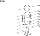
- Fig. 2 is a diagram showing an example of the multiple portions defined with respect to a pedestrian.
- M portions H 0 through H M-1 are defined.
- H 0 indicates the knees
- H 1 indicates the upper above-the-knee portions
- H 2 indicates the upper legs
- H 3 indicates the waist
- H 4 indicates the abdomen
- H 5 indicates the chest
- H 6 indicates the shoulders
- H 7 indicates the face.
- multiple portions B 0 through B 7 are defined at different heights.
- multiple portions C 0 through C 7 are defined at different heights.
- multiple portions P 0 through P 7 can be defined at different heights. However, there is substantially no difference in the profile between portions regardless of height. Accordingly, there is no need to distinguish the multiple portions P 0 through P 7 . That is to say, the data of a pole is handled as a single output P 0 .
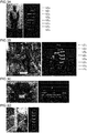
- Figs. 3A through 3D are diagrams showing multiple items of line data of a pedestrian, bicycle, automobile, and pole acquired by the three-dimensional sensor 20.
- the multiple items of line data represent the shapes of multiple portions defined beforehand.
- the processing device 40 generates intermediate data MD with respect to the kind of the object OBJ and the portion thereof for each item of line data LD.
- the intermediate data MD i may indicate the kind of the object OBJ and the portion thereof that corresponds to the line data LD i (horizontal line Li) in a statistical manner.
- the processing device 40 integrates the multiple items of intermediate data MD 1 through MD N that correspond to the multiple items of line data LD 1 through LD N so as to generate final data FD that indicates the kind of the object OBJ.
- the final data FD may indicate the kind of the object OBJ in a statistical manner.
- the processing device 40 includes multiple first calculation units 42_1 through 42_N and a second calculation unit 44.
- the blocks indicated by the calculation units 42 and 44 do not necessarily mean that such blocks are configured as independent hardware blocks.
- the multiple calculation units 42 and 44 may correspond to the single core.
- each core may function as a corresponding one of the multiple calculation units 42 and 44.
- the i-th (1 ⁇ i ⁇ N) calculation unit 42_i processes the corresponding line data LD i so as to generate the intermediate data MD i .
- the second calculation unit 44 integrates the intermediate data MD 1 through MD N generated by the multiple first calculation units 42_1 through 42_N so as to generate the final data FD.
- the above is the basic configuration of the object identification system 10.
- the configuration of the processing device 40 is not restricted in particular.
- the processing device 40 may be configured using a neural network. Description will be made below regarding a configuration evaluated by the present inventor. Description will be made with a neural network that corresponds to the first calculation unit 42 as a first neural network NN 1 , and with a neural network that corresponds to the second calculation unit 44 as a second neural network NN 2 .
- Fig. 4 is a block diagram showing an example configuration of the first neural network NN 1 .
- the first neural network NN 1 is configured including an input layer 50, three intermediate layers (hidden layers) 52, and an output layer 54.
- the number of units of the input layer 50 is determined according to the number of sample points for each line, and specifically, is designed to be 5,200.
- the three intermediate layers are designed with the number of units of 200, 100, and 50, respectively.
- the intermediate layers 52 support transformation using affine transformation and a sigmoid function.
- the output layer 54 supports attribution probability calculation using affine transformation and a softmax function.
- the intermediate data MD i includes multiple items of data Human-Oth through Human-7th, Car-0th through Car-7th, Bicycle-Oth through Bicycle-7th, and Pole-all, which indicate the probabilities of a given portion to be identified matching the portions H 0 through H 7 of a pedestrian, the portions C 0 through C 7 of an automobile, the portions B 0 through B 7 of a bicycle, and the portion P 0 of a pole, respectively.
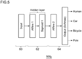
- Fig. 5 is a block diagram showing an example configuration of the second neural network NN 2 .
- the second neural network NN 2 is configured including an input layer 60, a single intermediate layer 62, and an output layer 64.
- the intermediate layer 62 is configured as a single layer designed such that the number of units is 50.
- the output layer 64 is designed so as to define four categories, i.e., the pedestrian category (Human), the automobile category (Car), the bicycle category (Bicycle), and the pole category (Pole). That is to say, the final data FD includes four items of data Human, Car, Bicycle, and Pole that correspond to the probabilities of a given object OBJ matching a pedestrian, automobile, bicycle, and pole, respectively.
- the first neural network NN 1 and the second neural network NN 2 are designed with the Adam method as the parameter update method, with a learning rate of 0.01, and with the number of iterations as 20,000.
- extraction, shifting, and normalization are preferably performed.
- Figs. 6A through 6C are diagrams for explaining the extraction of the object.
- Fig. 6A is a diagram showing an automobile employed as the object.
- Fig. 6B shows multiple items of line data LD 1 through LD 8 obtained when an image of the object shown in Fig. 6A is captured by means of the LiDAR.
- Fig. 6C shows the line data LD 1 through LD 8 extracted such that they include the object data.
- Shifting is data shifting processing for shifting the object such that it is positioned at the center.
- Normalization is processing for dividing the distance data by a predetermined value. For example, as the predetermined value, the distance (reference distance) between the three-dimensional sensor 20 and a predetermined portion of the object OBJ set in the learning may be employed. This processing normalizes the line data such that it becomes a value in the vicinity of 1.
- Figs. 7A through 7C are diagrams for explaining a first learning method.
- the learning data is acquired by measuring multiple objects by means of LiDAR.
- the object candidates (pedestrian, automobile, pole, person riding a bicycle, etc.) to be identified are measured under different conditions (e.g., at various distances and in various directions), so as to prepare frame data FD 1 , FD 2 , ..., for learning.
- the effective line data in which the line crosses the object may be used.
- the frame data FD 1 is acquired for a pedestrian
- the lowermost two items of line data LD 11 and FD 12 cross the ground, and do not cross the pedestrian. Accordingly, judgment may be made that the line data LD 11 and FD 12 are not used in the learning.
- first calculation unit 42 learning is performed for the first calculation unit (first neural network) 42.
- first calculation unit 42 multiple items of effective line data LD ij included in the multiple items of frame data are individually input to the first calculation unit 42 together with teaching data TD ij .
- the learning results thus obtained with respect to such a single first calculation unit 42 are used for all the first calculation units 42.
- learning is performed for the second calculation unit 44.
- the multiple first calculation units 42 are coupled to the second calculation unit (second neural network) 44.
- the processing device 40 receives multiple items of frame data FD 1 , FD 2 , ..., and outputs multiple items of intermediate data MD 1 through MD 8 from the processing device 40.
- a set of multiple items of intermediate data MD 1 through MD 8 is generated for each frame FD i by means of the multiple first calculation units 42, which is supplied to the second calculation unit 44 configured as a downstream stage.
- the second calculation unit 44 receives the teaching data TD i that indicates the kind of the object included in the current frame data FD i in addition to the set of the intermediate data MD 1 through MD 6 .
- the LiDAR employed in this investigation was configured to provide eight horizontal lines.
- the horizontal lines were designed with irradiation angles of -18.25°, - 15.42°, - 12.49°, -9.46°, -6.36°, -3.19°, 0°, and 3.2°, in this order from the bottom (angular resolution in the vertical direction).
- the angular resolution in the horizontal direction is designed to be 0.035°.
- Figs. 8A and 8B are diagrams for explaining image capture of a pedestrian. Description will be made regarding an example in which the distance (reference distance) from the center of the LiDAR up to the object OBJ is 3 m. Furthermore, description will be made assuming that the pedestrian sample is an adult male pedestrian with a height of 166 cm, and the object image is captured in nine directions (0°, 22.5°, 45°, 67.5°, 90°, 112.5°, 135°, 157.5°, 0°, and 180°). It should be noted that the direction in which the LiDAR faces the front (face, headlamp) of the object OBJ is defined to be 0°. Regarding the pedestrian, the LiDAR is set with a tilt angle (elevation angle) of 7° in the vertical direction such that the eight horizontal lines match the eight portions H0 through H7 shown in Fig. 2 .
- image data was acquired in a state in which a person was mounted on a stopped bicycle.
- the image data was acquired in nine directions in the same manner as in the image data acquisition for the pedestrian.
- image data was acquired for a single kind of automobile in three directions (0°, 90°, and 180°).
- image data was acquired for six pole samples in an arbitrary direction.
- the machine learning was performed for the pedestrian and the bicycle with 3,600 frames of training data, for the automobile with 3,000 frames of training data, and for the pole with 1,700 frames of training data.
- the learning method described with reference to Figs. 7A through 7C was employed.
- Fig. 9 is a diagram showing the accuracy rate for the classification of 25 categories (sub-categories) provided by the first neural network NN 1 .
- the other categories represent the accuracy rates for the classification of the respective portions of the pedestrian, automobile, bicycle, and pole.
- Fig. 10 is a diagram showing the accuracy rates for the classification of the four categories provided by the second neural network NN 2 .
- the other categories represent the accuracy rates for the classification of the pedestrian (Human), automobile (Car), bicycle (Bicycle), and pole (Pole).
- this arrangement provides an accuracy rate of 100% for the pedestrian (Human), automobile (Car), and pole (Pole). However, this arrangement provides an accuracy rate of only 97.8% for only the bicycle (Bicycle). Accordingly, it can be understood that the total accuracy rate is affected by the degraded accuracy rate for the bicycle.
- this arrangement is capable of judging the kind of the object with a dramatically high accuracy rate using only eight horizontal lines.
- this arrangement requires only a small number of horizontal lines, i.e., only eight lines, thereby allowing the processing capacity required for the processing device 40 to be reduced.
- the effects were evaluated with a fixed distance of 3 m between the object and the LiDAR. In actuality, the distance varies. Accordingly, the learning may preferably be performed for each range after various distances are classified into multiple ranges.
- Fig. 11 is a block diagram showing an automobile including the object identification system 10.
- the automobile 100 includes headlamps 102L and 102R. From among the components of the object identification system 10, at least the three-dimensional sensor 20 is built into at least one from among the headlamps 102L and 102R. Each headlamp 102 is positioned at a frontmost end of the vehicle body, which is most advantageous as a position where the three-dimensional sensor 20 is to be installed for detecting an object in the vicinity.
- the processing device 40 may be built into the headlamp 102. Also, the processing device 40 may be provided on the vehicle side. For example, from among the functions of the processing device 40, the function of generating the intermediate data may be provided by an internal component of the headlamp 102. Also, the function of generating the final data may be provided by another component on the vehicle side.
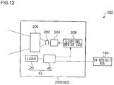
- Fig. 12 is a block diagram showing an automotive lamp 200 including the object identification system 10.
- the automotive lamp 200 includes a light source 202, a lighting circuit 204, and an optical system 206. Furthermore, the automotive lamp 200 includes the three-dimensional sensor 20 and the processing device 40.
- the information with respect to the object OBJ detected by the processing device 40 is transmitted to the in-vehicle ECU 104.
- the in-vehicle ECU may support autonomous driving based on the information thus transmitted.
- the information with respect to the object OBJ detected by the processing device 40 may be used to support the light distribution control operation of the automotive lamp 200.
- the lighting device ECU 208 generates a suitable light distribution pattern based on the information with respect to the kind of the object OBJ and the position thereof thus generated by the processing device 40.
- the lighting circuit 204 and the optical system 206 operate so as to provide the light distribution pattern generated by the lighting device ECU 208.
- Figs. 13A and 13B are diagrams each showing the relation between the height at which the LiDAR is installed and the object.
- Fig. 13A shows a case in which the LiDAR is installed at a height of 145 cm in the learning.
- the lower three items of line data are ineffective. That is to say, the line data LD 4 through LD 8 , which are the fourth line data through the eighth line data from the bottom, are used for the learning.
- the LiDAR is installed at a height of 70 cm, which is lower than that in the learning. Furthermore, description will be made assuming that the distance between the pedestrian and the LiDAR is smaller than that in the learning.
- the line data LD 1 through LD 3 match no particular portion (no particular sub-category).
- Fig. 13C shows the final data obtained by the object identification system 10 in a situation shown in Fig. 13B in a case in which it has learned using the first learning method.
- the object must be identified as a pedestrian.
- false identification is obtained that there is a higher probability of other objects that differ from a pedestrian. It can be considered that this is because, with the first learning method, the classification supported by the second calculation unit 44 strongly depends on the order and combination of the sub-categories. That is to say, in a case of employing the first learning method, in some cases, such an arrangement has the potential to restrict the height at which the three-dimensional sensor is to be installed in the actual use stage due to the height that was used in the learning stage.
- a second learning method is designed to have a function for reducing such a restriction.
- the first calculation units 42 each learn using the same learning method as with the first learning method.
- Fig. 14 is a diagram for explaining the learning process for the second calculation unit 44 using the second learning method.
- this arrangement instructs the second calculation unit 44 to learn while changing the correspondence relation 46 between the outputs of the multiple first calculation units 42 that have learned and multiple input nodes I1 through 18 of the second calculation unit 44.
- the correspondence relation 46 may be changed at random for each frame data FD i .
- this arrangement may support the learning for each frame data FD i while switching the correspondence relation between multiple patterns.
- N 8
- there are 56 ( 8 ⁇ 7) input/output combinations. Accordingly, this arrangement may support the learning for each frame data with respect to all the combinations.
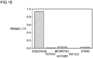
- Fig. 15 is a diagram for explaining the effect of the second learning method.
- Fig. 15 shows the final data FD obtained by the object identification system 10 that has learned using the second learning method in a case in which a pedestrian is assumed in the situation shown in Fig. 13B . This arrangement allows the accuracy rate for the identification of a pedestrian to be raised as compared with the final data shown in Fig. 13C obtained using the first learning method.
- the correspondence relation between the multiple first calculation units 42 and the multiple inputs of the second calculation unit 44 is changed.
- This arrangement provides improved degree of freedom in installing the three-dimensional sensor such as the LiDAR or the like.
- Fig. 16 is a block diagram showing an object identification system 10A according to a modification.
- first calculation units 42A are configured as a convolutional neural network.
- a convolutional neural network handles a two-dimensional image of M ⁇ N pixels.
- the convolutional neural network handles one-dimensional line data as a processing target, which is a new idea.
- the convolutional neural network is configured as a combination of a convolutional layer and a pooling layer.
- the learning method is modified so as to provide an improved identification capability.
- the configuration of the processing device is modified so as to provide improved identification.
- Fig. 17 is a block diagram showing an object identification system 10B according to a second embodiment.
- the object identification system 10B includes a three-dimensional sensor 20 and a processing device 70.
- the processing device 70 includes multiple first neural networks 72_1 through 72_N, a combining processing unit 74, and a second neural network 76.
- the first intermediate data MD 1_i indicates the probability of matching between corresponding line data LD i and each of the multiple portions (sub-categories) of the multiple kinds (categories).
- the combining processing unit 74 receives the multiple items of first intermediate data MD 1_1 through MD 1_N that correspond to the multiple items of line data LD 1 through LD N , and combines the first intermediate data thus received, so as to generate at least one item of second intermediate data MD 2 .
- Fig. 17 shows an example configured to support a single item of second intermediate data MD 2 . That is to say, all the items of first intermediate data MD 1_1 through MD 1_N are combined so as to generate a single item of second intermediate data MD 2 .
- the second intermediate data MD 2 indicates the probability of matching between corresponding line data LD i and each of the multiple portions (sub-categories) of the multiple kinds (categories).
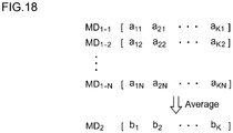
- Fig. 18 is a diagram showing an example of the processing supported by the combining processing unit 74.
- the i-th first intermediate data MD 1_i includes K elements a1i through a Ki .
- the combining processing unit 74 calculates an average of the multiple items of the first intermediate data MD 1_1 through MD 1_N , which is employed as the second intermediate data MD 2 .
- the j-th element bj of the second intermediate data MD 2 is represented by the following Expression.
- the second neural network 76 receives the second intermediate data MD 2 , and generates final data FD that indicates the probability of matching between the object OBJ and each of the multiple kinds (categories).
- the second neural network 76 may be configured in the same manner as the neural network shown in Fig. 5 .
- the object identification system 10B supports learning using the first learning method described above. That is to say, the object identification system 10B instructs the first neural networks 72 to learn using multiple items of line data measured for multiple portions of multiple kinds. A common learning result is applied to all the first networks 72_1 through 72_N.
- the second neural network 76 is instructed to learn in a state in which the outputs of the first neural networks 72_1 through 72_N after learning are coupled to the second neural network 76 via the combining processing unit 74.
- Fig. 19 is a diagram showing the final data obtained by the object identification system according to the second embodiment in a situation shown in Fig. 13B .
- the second embodiment such an arrangement allows the probability of the identification of a pedestrian to be raised as compared with the final data shown in Fig. 13C obtained by a combination of the first embodiment and the first learning method.
- ci represents the weighting coefficient for each height (line).
- the combining processing unit 74 may calculate the sum total.
- the combining processing unit 74 may select the maximum value.
- b j max a j 1 , a j 2 , ... , a jK
- first intermediate data MD 1_1 through MD 1_N may be combined so as to generate two items of second intermediate data MD 2 _ 1 and MD 2_2 ⁇
- the multiple items of first intermediate data MD 1_1 through MD 1_N may be divided into two groups.
- the second intermediate data MD 2_1 may be generated based on one from among the two groups thus divided.
- the second intermediate data MD 2_2 may be generated based on the other one from among the two groups thus divided.
- Fig. 17 is a block diagram showing an object identification system 10C according to a modification 3.
- a convolutional neural network is applied to the object identification system 10B shown in Fig. 17 .
- N is set to a value on the order of 4 to 12 giving consideration to the calculation power of the processing device 40 and the required object OBJ identification capability.
- the object may be defined as a different kind (category) for each orientation as viewed from the user's vehicle. That is to say, the same object is identified as a different kind according to the orientation thereof, e.g., whether or not the object is positioned with a face-to-face orientation with respect to the user's vehicle. This is because such identification is advantageous in estimating the object OBJ moving direction.
- the processing device 40 may be configured of only a hardware component using an FPGA or the like.
- the present invention is not restricted to such an application.
- the object identification system 10 may be fixedly installed on transportation infrastructure such as a traffic light, traffic sign, or the like. That is to say, the present invention is applicable to a fixed-point observation application.
- the present invention relates to an object identification system.
- 10 object identification system 20 three-dimensional sensor, 40 processing device, 42 first calculation unit, 44 second calculation unit, NN 1 first neural network, NN 2 second neural network, 70 processing device, 72 first neural network, 74 combining processing unit, 76 second neural network, 50 input layer, 52 intermediate layer, 54 output layer, 60 input layer, 62 intermediate layer, 64 output layer, 100 automobile, 102 headlamp, 104 in-vehicle ECU, 200 automotive lamp, 202 light source, 204 lighting circuit, 206 optical system, 208 lighting device ECU.
Landscapes
- Engineering & Computer Science (AREA)
- Physics & Mathematics (AREA)
- General Physics & Mathematics (AREA)
- Remote Sensing (AREA)
- Radar, Positioning & Navigation (AREA)
- Electromagnetism (AREA)
- Computer Networks & Wireless Communication (AREA)
- Theoretical Computer Science (AREA)
- Data Mining & Analysis (AREA)
- Multimedia (AREA)
- Artificial Intelligence (AREA)
- General Engineering & Computer Science (AREA)
- Evolutionary Computation (AREA)
- Evolutionary Biology (AREA)
- Computer Vision & Pattern Recognition (AREA)
- Bioinformatics & Computational Biology (AREA)
- Bioinformatics & Cheminformatics (AREA)
- Life Sciences & Earth Sciences (AREA)
- Probability & Statistics with Applications (AREA)
- Image Analysis (AREA)
- Traffic Control Systems (AREA)
- Optical Radar Systems And Details Thereof (AREA)
Abstract
Description
- The present invention relates to an object identification system.
- Candidates of vehicle sensors include Light Detection and Ranging, Laser Imaging Detection and Ranging (LiDAR), cameras, millimeter-wave radars, ultrasonic sonars, and so forth. In particular, LiDAR has advantages as compared with other sensors. Examples of such advantages include: (i) an advantage of being capable of identifying an object based on point group data; (ii) an advantage in employing active sensing of providing high-precision detection even in bad weather conditions; (iii) an advantage of providing wide-range measurement; etc. Accordingly, LiDAR is anticipated to become mainstream in vehicle sensing systems.
-
- [Patent document 1]
Japanese Patent Application Laid Open No.2017-56935 - [Patent document 2]
Japanese Patent Application Laid Open No.2009-98023 - The precision of object identification based on the point group data generated by the LiDAR increases according to an increase in the resolution of the point group data. However, this involves a drastic increase in calculation costs. In consideration of a case in which the LiDAR is mounted on a vehicle, in some cases, it may be necessary to mount a low-cost, low-end processing device. In this case, such an arrangement naturally requires the number of scan lines to be reduced.
- The present invention has been made in view of such a situation. Accordingly, it is an exemplary purpose of an embodiment of the present invention to provide a system, apparatus, and method that are capable of identifying an object using only a small number of horizontal lines.
- An embodiment of the present invention relates to an object identification system. The object identification system includes: a three-dimensional sensor structured to generate multiple items of line data for multiple horizontal lines defined with different heights; and a processing device structured to identify the kind (category or class) of an object based on the multiple items of line data. The processing device includes: multiple first neural networks each of which is structured to generate first intermediate data relating to a corresponding one from among the multiple items of line data such that the first intermediate data indicates a probability of matching (attribution probability) between the corresponding line data and each of multiple portions of multiple kinds; a combining processing unit structured to receive the multiple items of first intermediate data that corresponds to the multiple items of line data, and to combine the multiple items of first intermediate data so as to generate at least one item of second intermediate data; and a second neural network structured to receive the at least one item of second intermediate data, and generate final data that indicates a probability of matching between the object and each of the multiple kinds.
- Another embodiment of the present invention relates to a motor vehicle. The motor vehicle may include the object identification system described above.
- Also, the three-dimensional sensor may be built into a headlamp.
- Yet another embodiment of the present invention relates to an automotive lamp. The automotive lamp may include the object identification system described above.
- With the present invention, object identification is supported using a small number of horizontal lines.
-
-
Fig. 1 is a block diagram showing an object identification system according to a first embodiment; -
Fig. 2 is a diagram showing an example of multiple portions defined for a pedestrian; -
Figs. 3A through 3D are diagrams showing multiple items of line data obtained when images of a pedestrian, bicycle, automobile, and pole are respectively captured; -
Fig. 4 is a block diagram showing an example configuration of a first neural network; -
Fig. 5 is a block diagram showing an example configuration of a second neural network; -
Figs. 6A through 6C are diagrams for explaining extraction of the object; -
Figs. 7A through 7C are diagrams for explaining a first learning method; -
Figs. 8A and 8B are diagrams for explaining image capture of a pedestrian; -
Fig. 9 is a diagram showing the classification accuracy rates for 25 categories provided by the first neural networks; -
Fig. 10 is a diagram showing the classification accuracy rates for four categories provided by the second neural network; -
Fig. 11 is a block diagram showing an automobile including an object identification system; -
Fig. 12 is a block diagram showing an automotive lamp including an object identification system; -
Figs. 13A and 13B are diagrams showing the relation between the height of the LiDAR and the object, andFig. 13C is a diagram showing final data obtained in a situation shown inFig. 13B by means of an object identification system that has learned using the first learning method; -
Fig. 14 is a diagram for explaining learning process for a second calculation unit using a second learning method; -
Fig. 15 is a diagram for explaining the effects of the second learning method; -
Fig. 16 is a block diagram showing an object identification system according to a modification. -
Fig. 17 is a block diagram showing an object identification system according to a second embodiment; -
Fig. 18 is a diagram showing an example of processing supported by a combining processing unit; -
Fig. 19 is a diagram showing final data obtained by the object identification system according to the second embodiment in a situation shown inFig. 13B ; and -
Fig. 20 is a block diagram showing an object identification system according to amodification 3. - An embodiment disclosed in the present specification relates to an object identification system. The object identification system includes: a three-dimensional sensor structured to generate multiple items of line data for multiple horizontal lines defined with different heights; and a processing device structured to identify the kind (category or class) of an object based on the multiple items of line data. The processing device includes: multiple first neural networks each of which is structured to generate first intermediate data relating to a corresponding one from among the multiple items of line data such that the first intermediate data indicates a probability of matching (attribution probability) between the corresponding line data and each of multiple portions of multiple kinds; a combining processing unit structured to receive the multiple items of first intermediate data that corresponds to the multiple items of line data, and to combine the multiple items of first intermediate data so as to generate at least one item of second intermediate data; and a second neural network structured to receive the at least one item of second intermediate data, and generate final data that indicates a probability of matching between the object and each of the multiple kinds.
- This arrangement allows the kind of an object to be judged using a small number of horizontal lines. Furthermore, by combining the multiple items of first intermediate data, this arrangement allows the height-direction dependence to be reduced. This relaxes the restriction imposed on the installation of the three-dimensional sensor. It should be noted that the combining processing does not involve complete loss of the information with respect to the height direction. That is to say, even after the combining processing, each portion continues to have height information.
- Also, the number of the at least one item of second intermediate data may be one. Also, the second intermediate data may be obtained based on all the multiple items of first intermediate data.
- Also, the number of the at least one item of second intermediate data may be plural. Also, each item of the second intermediate data may be obtained based on a predetermined number of consecutive items selected from among the multiple items of first intermediate data.
- Also, the at least one item of second intermediate data may be an average or a sum total of a predetermined number of corresponding items of first intermediate data. Also, the average value may be calculated as a simple average value. Also, the average value may be calculated as a weighted average value. Also, the at least one item of second intermediate data may be obtained as the maximum value of corresponding items of the first intermediate data.
- Also, the processing device may execute: instructing the first neural networks to learn using multiple items of line data obtained by measuring multiple portions of multiple kinds; and instructing the second neural network to learn in a state in which outputs of the multiple first neural networks after learning are combined to the second neural network via the combining processing unit.
- Also, the processing device may support normalization as preprocessing in which each value included in each line data is divided by a predetermined value.
- Also, the kinds of the object may include at least a pedestrian, a person on a bicycle, and a motor vehicle.
- Description will be made below regarding the present invention based on preferred embodiments with reference to the drawings. The same or similar components, members, and processes are denoted by the same reference numerals, and redundant description thereof will be omitted as appropriate. The embodiments have been described for exemplary purposes only, and are by no means intended to restrict the present invention. Also, it is not necessarily essential for the present invention that all the features or a combination thereof be provided as described in the embodiments.
-
Fig. 1 is a block diagram showing anobject identification system 10 according to a first embodiment. Theobject identification system 10 is configured as an in-vehicle system to be mounted on a vehicle such as an automobile, motorcycle, or the like. Theobject identification system 10 judges the kind (which is also referred to as a "category" or "class") of the object OBJ in the vicinity of the vehicle. - The
object identification system 10 mainly includes a three-dimensional sensor 20 and aprocessing device 40. The three-dimensional sensor 20 generates multiple items of line data LD1 through LDN with respect to multiple horizontal lines L1 through LN defined with different heights. The number N of the horizontal lines is not restricted in particular. Specifically, the number N of the horizontal lines is set to 20 or less, and is preferably set on the order of 4 to 12. Each item of line data LD includes distance information with respect to the distance up to each of multiple sampling points P defined along the corresponding horizontal line L. The data set of the multiple items of line data LD1 through LDN will be referred to as "distance measurement data". The three-dimensional sensor 20 is not restricted in particular. However, in a case in which there is a need to identify an object with small irregularities, such as a pedestrian, with high precision, a LiDAR is preferably employed. The number N of the horizontal lines represents a so-called resolution in the vertical direction. The configuration of the LiDAR is not restricted in particular. That is to say, the LiDAR may be configured as a scanning LiDAR or a non-scanning LiDAR. - The
processing device 40 identifies the kind (category) of the object based on the measurement data including the multiple items of line data LD1 through LDN. Theprocessing device 40 is configured to handle data including a single object as a processing target. In a case in which an item of distance measurement data includes multiple objects, the distance measurement data is divided by pre-processing into multiple sub-frames each including a single object. Theprocessing device 40 handles each sub-frame as a processing unit. - The
processing device 40 may be provided as a combination of a processor (hardware component) such as a Central Processing Unit (CPU), Graphics Processing Unit (GPU), microcontroller, or the like, and a software program to be executed by the processor (hardware component). Theprocessing device 40 may be configured as a combination of multiple processors. - For example, examples of the kind of the object include a pedestrian, bicycle, automobile, pole, and the like. Regarding a pedestrian, a pedestrian as viewed from the front, a pedestrian as viewed from the rear, and a pedestrian as viewed from the side may be classified and defined as the same kind of object. The same can be said of an automobile and bicycle. In the present embodiment, this definition is employed.
- With the present embodiment, the object OBJ is defined such that it has multiple portions (which will be referred to as "categories or sub-categories") positioned at different heights.
Fig. 2 is a diagram showing an example of the multiple portions defined with respect to a pedestrian. Regarding the pedestrian, M portions H0 through HM-1 are defined. Description will be made in the present embodiment regarding an arrangement in which M = N = 8. Here, H0 indicates the knees, H1 indicates the upper above-the-knee portions, H2 indicates the upper legs, H3 indicates the waist, H4 indicates the abdomen, H5 indicates the chest, H6 indicates the shoulders, and H7 indicates the face. - In the same manner, regarding a bicycle, multiple portions B0 through B7 are defined at different heights. Also, regarding an automobile, multiple portions C0 through C7 are defined at different heights. Regarding a pole, multiple portions P0 through P7 can be defined at different heights. However, there is substantially no difference in the profile between portions regardless of height. Accordingly, there is no need to distinguish the multiple portions P0 through P7. That is to say, the data of a pole is handled as a single output P0.
-
Figs. 3A through 3D are diagrams showing multiple items of line data of a pedestrian, bicycle, automobile, and pole acquired by the three-dimensional sensor 20. InFig. 3 , the multiple items of line data represent the shapes of multiple portions defined beforehand. - Returning to
Fig. 1 , theprocessing device 40 generates intermediate data MD with respect to the kind of the object OBJ and the portion thereof for each item of line data LD. The intermediate data MDi may indicate the kind of the object OBJ and the portion thereof that corresponds to the line data LDi (horizontal line Li) in a statistical manner. - Subsequently, the
processing device 40 integrates the multiple items of intermediate data MD1 through MDN that correspond to the multiple items of line data LD1 through LDN so as to generate final data FD that indicates the kind of the object OBJ. The final data FD may indicate the kind of the object OBJ in a statistical manner. - As functional components, the
processing device 40 includes multiple first calculation units 42_1 through 42_N and asecond calculation unit 44. The blocks indicated by thecalculation units processing device 40 is configured as a single core, themultiple calculation units processing device 40 includes multiple cores, each core may function as a corresponding one of themultiple calculation units - The i-th (1 ≤ i ≤ N) calculation unit 42_i processes the corresponding line data LDi so as to generate the intermediate data MDi. The
second calculation unit 44 integrates the intermediate data MD1 through MDN generated by the multiple first calculation units 42_1 through 42_N so as to generate the final data FD. - The above is the basic configuration of the
object identification system 10. The configuration of theprocessing device 40 is not restricted in particular. For example, theprocessing device 40 may be configured using a neural network. Description will be made below regarding a configuration evaluated by the present inventor. Description will be made with a neural network that corresponds to thefirst calculation unit 42 as a first neural network NN1, and with a neural network that corresponds to thesecond calculation unit 44 as a second neural network NN2. -
Fig. 4 is a block diagram showing an example configuration of the first neural network NN1. The first neural network NN1 is configured including aninput layer 50, three intermediate layers (hidden layers) 52, and anoutput layer 54. The number of units of theinput layer 50 is determined according to the number of sample points for each line, and specifically, is designed to be 5,200. The three intermediate layers are designed with the number of units of 200, 100, and 50, respectively. Theintermediate layers 52 support transformation using affine transformation and a sigmoid function. Theoutput layer 54 supports attribution probability calculation using affine transformation and a softmax function. - In the
output layer 54, a total of 25 categories, i.e., the categories of the portions H0 through H7 of a pedestrian, the categories of the portions C0 through C7 of an automobile, the categories of the portions B0 through B7 of a bicycle, and the category of the portion P0 of a pole. The intermediate data MDi includes multiple items of data Human-Oth through Human-7th, Car-0th through Car-7th, Bicycle-Oth through Bicycle-7th, and Pole-all, which indicate the probabilities of a given portion to be identified matching the portions H0 through H7 of a pedestrian, the portions C0 through C7 of an automobile, the portions B0 through B7 of a bicycle, and the portion P0 of a pole, respectively. -
Fig. 5 is a block diagram showing an example configuration of the second neural network NN2. The second neural network NN2 is configured including aninput layer 60, a singleintermediate layer 62, and anoutput layer 64. Theinput layer 60 is designed such that the number of units thereof is a product of the number of the previous first neural networks NN1 (N = 8) and the number of categories (25), i.e., 200. Theintermediate layer 62 is configured as a single layer designed such that the number of units is 50. Theoutput layer 64 is designed so as to define four categories, i.e., the pedestrian category (Human), the automobile category (Car), the bicycle category (Bicycle), and the pole category (Pole). That is to say, the final data FD includes four items of data Human, Car, Bicycle, and Pole that correspond to the probabilities of a given object OBJ matching a pedestrian, automobile, bicycle, and pole, respectively. - As common settings, the first neural network NN1 and the second neural network NN2 are designed with the Adam method as the parameter update method, with a learning rate of 0.01, and with the number of iterations as 20,000.
- As the preprocessing for the first neural network NN1, extraction, shifting, and normalization are preferably performed.
- Extraction is processing for removing the background so as to extract the object OBJ.
Figs. 6A through 6C are diagrams for explaining the extraction of the object.Fig. 6A is a diagram showing an automobile employed as the object.Fig. 6B shows multiple items of line data LD1 through LD8 obtained when an image of the object shown inFig. 6A is captured by means of the LiDAR.Fig. 6C shows the line data LD1 through LD8 extracted such that they include the object data. - Shifting is data shifting processing for shifting the object such that it is positioned at the center. Normalization is processing for dividing the distance data by a predetermined value. For example, as the predetermined value, the distance (reference distance) between the three-
dimensional sensor 20 and a predetermined portion of the object OBJ set in the learning may be employed. This processing normalizes the line data such that it becomes a value in the vicinity of 1. - Next, description will be made regarding the machine learning.
Figs. 7A through 7C are diagrams for explaining a first learning method. As shown inFig. 7A , first, the data (learning data or teaching data) to be used for learning is measured. The learning data is acquired by measuring multiple objects by means of LiDAR. Specifically, the object candidates (pedestrian, automobile, pole, person riding a bicycle, etc.) to be identified are measured under different conditions (e.g., at various distances and in various directions), so as to prepare frame data FD1, FD2, ..., for learning. Each frame data FDi (i = 1, 2, ...) includes N (eight, in this example) items of line data. However, in the learning, only the effective line data in which the line crosses the object may be used. For example, in a case in which the frame data FD1 is acquired for a pedestrian, the lowermost two items of line data LD11 and FD12 cross the ground, and do not cross the pedestrian. Accordingly, judgment may be made that the line data LD11 and FD12 are not used in the learning. - Subsequently, learning is performed for the first calculation unit (first neural network) 42. As shown in
Fig. 7B , multiple items of effective line data LDij included in the multiple items of frame data are individually input to thefirst calculation unit 42 together with teaching data TDij. For example, when the line data LD18 of the frame FD1 is input, the teaching data TDij that represents the kind (category) = "pedestrian" and the portion (sub-category) = "face of pedestrian" is input. - The learning results thus obtained with respect to such a single
first calculation unit 42 are used for all thefirst calculation units 42. Subsequently, learning is performed for thesecond calculation unit 44. Specifically, as shown inFig. 7B , the multiplefirst calculation units 42 are coupled to the second calculation unit (second neural network) 44. In this state, multiple items of frame data FD1, FD2, ..., are individually input to theprocessing device 40. A set of multiple items of intermediate data MD1 through MD8 is generated for each frame FDi by means of the multiplefirst calculation units 42, which is supplied to thesecond calculation unit 44 configured as a downstream stage. Thesecond calculation unit 44 receives the teaching data TDi that indicates the kind of the object included in the current frame data FDi in addition to the set of the intermediate data MD1 through MD6. For example, in a case in which the frame data FDi acquired by image capture for a pedestrian is input to theprocessing device 40, the teaching data TDi that indicates the kind = "pedestrian" is supplied to thesecond calculation unit 44. This processing is executed for the multiple items of frame data, thereby providing the learning for thesecond calculation unit 44. - Description will be made regarding an experiment executed in order to investigate the effects of the
object identification system 10 having the above-described configuration. - The LiDAR employed in this investigation was configured to provide eight horizontal lines. The horizontal lines were designed with irradiation angles of -18.25°, - 15.42°, - 12.49°, -9.46°, -6.36°, -3.19°, 0°, and 3.2°, in this order from the bottom (angular resolution in the vertical direction). The angular resolution in the horizontal direction is designed to be 0.035°. The image capture range was designed to be a range of 0 to 180°. Accordingly, each item of line data includes values of 5,200 (= 180/0.035) sample points.
-
Figs. 8A and 8B are diagrams for explaining image capture of a pedestrian. Description will be made regarding an example in which the distance (reference distance) from the center of the LiDAR up to the object OBJ is 3 m. Furthermore, description will be made assuming that the pedestrian sample is an adult male pedestrian with a height of 166 cm, and the object image is captured in nine directions (0°, 22.5°, 45°, 67.5°, 90°, 112.5°, 135°, 157.5°, 0°, and 180°). It should be noted that the direction in which the LiDAR faces the front (face, headlamp) of the object OBJ is defined to be 0°. Regarding the pedestrian, the LiDAR is set with a tilt angle (elevation angle) of 7° in the vertical direction such that the eight horizontal lines match the eight portions H0 through H7 shown inFig. 2 . - Regarding the bicycle, as shown in
Fig. 3B , image data was acquired in a state in which a person was mounted on a stopped bicycle. The image data was acquired in nine directions in the same manner as in the image data acquisition for the pedestrian. - Regarding the automobile, image data was acquired for a single kind of automobile in three directions (0°, 90°, and 180°). Regarding the pole, image data was acquired for six pole samples in an arbitrary direction.
- The machine learning was performed for the pedestrian and the bicycle with 3,600 frames of training data, for the automobile with 3,000 frames of training data, and for the pole with 1,700 frames of training data. The learning method described with reference to
Figs. 7A through 7C was employed. - Subsequently, the learning results were evaluated for the pedestrian and the bicycle with 360 frames of test data, and for the automobile and the pole with 300 frames of test data.
Fig. 9 is a diagram showing the accuracy rate for the classification of 25 categories (sub-categories) provided by the first neural network NN1. The category "Total" shown at the top indicates the total accuracy rate of the classification of the 10,560 (= (360 + 360 + 300 + 300) frames × 8 lines) items of line data thus input as the test data. The other categories represent the accuracy rates for the classification of the respective portions of the pedestrian, automobile, bicycle, and pole. -
Fig. 10 is a diagram showing the accuracy rates for the classification of the four categories provided by the second neural network NN2. The category "Total" shown at the top indicates the total accuracy rate of the classification of the 1,320 (=360 + 360 + 300 + 300) frames thus input as the test data. The other categories represent the accuracy rates for the classification of the pedestrian (Human), automobile (Car), bicycle (Bicycle), and pole (Pole). - As can be understood from
Fig. 10 , this arrangement provides an accuracy rate of 100% for the pedestrian (Human), automobile (Car), and pole (Pole). However, this arrangement provides an accuracy rate of only 97.8% for only the bicycle (Bicycle). Accordingly, it can be understood that the total accuracy rate is affected by the degraded accuracy rate for the bicycle. - As described above, with the
object identification system 10 according to the second embodiment, this arrangement is capable of judging the kind of the object with a dramatically high accuracy rate using only eight horizontal lines. - Furthermore, this arrangement requires only a small number of horizontal lines, i.e., only eight lines, thereby allowing the processing capacity required for the
processing device 40 to be reduced. - In this example, the effects were evaluated with a fixed distance of 3 m between the object and the LiDAR. In actuality, the distance varies. Accordingly, the learning may preferably be performed for each range after various distances are classified into multiple ranges.
-
Fig. 11 is a block diagram showing an automobile including theobject identification system 10. Theautomobile 100 includesheadlamps 102L and 102R. From among the components of theobject identification system 10, at least the three-dimensional sensor 20 is built into at least one from among theheadlamps 102L and 102R. Eachheadlamp 102 is positioned at a frontmost end of the vehicle body, which is most advantageous as a position where the three-dimensional sensor 20 is to be installed for detecting an object in the vicinity. Theprocessing device 40 may be built into theheadlamp 102. Also, theprocessing device 40 may be provided on the vehicle side. For example, from among the functions of theprocessing device 40, the function of generating the intermediate data may be provided by an internal component of theheadlamp 102. Also, the function of generating the final data may be provided by another component on the vehicle side. -
Fig. 12 is a block diagram showing anautomotive lamp 200 including theobject identification system 10. Theautomotive lamp 200 includes alight source 202, alighting circuit 204, and anoptical system 206. Furthermore, theautomotive lamp 200 includes the three-dimensional sensor 20 and theprocessing device 40. The information with respect to the object OBJ detected by theprocessing device 40 is transmitted to the in-vehicle ECU 104. The in-vehicle ECU may support autonomous driving based on the information thus transmitted. - Also, the information with respect to the object OBJ detected by the
processing device 40 may be used to support the light distribution control operation of theautomotive lamp 200. Specifically, thelighting device ECU 208 generates a suitable light distribution pattern based on the information with respect to the kind of the object OBJ and the position thereof thus generated by theprocessing device 40. Thelighting circuit 204 and theoptical system 206 operate so as to provide the light distribution pattern generated by thelighting device ECU 208. - With the first learning method shown in
Figs. 7A through 7C , in some cases, this arrangement involves learning that strongly depends on the installation of the LiDAR (height, elevation angle, or the distance up to the object).Figs. 13A and 13B are diagrams each showing the relation between the height at which the LiDAR is installed and the object.Fig. 13A shows a case in which the LiDAR is installed at a height of 145 cm in the learning. In this case, the lower three items of line data are ineffective. That is to say, the line data LD4 through LD8, which are the fourth line data through the eighth line data from the bottom, are used for the learning. - Description will be made assuming that, in the actual operation, as shown in
Fig. 13B , the LiDAR is installed at a height of 70 cm, which is lower than that in the learning. Furthermore, description will be made assuming that the distance between the pedestrian and the LiDAR is smaller than that in the learning. In the state shown inFig. 13B , the line data LD1 through LD3 match no particular portion (no particular sub-category). The line data LD4 through LD7 match the portion (sub-category) = "legs". The line data LD8 matches the portion (sub-category) = "abdomen". -
Fig. 13C shows the final data obtained by theobject identification system 10 in a situation shown inFig. 13B in a case in which it has learned using the first learning method. In this case, the object must be identified as a pedestrian. However, false identification is obtained that there is a higher probability of other objects that differ from a pedestrian. It can be considered that this is because, with the first learning method, the classification supported by thesecond calculation unit 44 strongly depends on the order and combination of the sub-categories. That is to say, in a case of employing the first learning method, in some cases, such an arrangement has the potential to restrict the height at which the three-dimensional sensor is to be installed in the actual use stage due to the height that was used in the learning stage. A second learning method is designed to have a function for reducing such a restriction. - With the second learning method, the
first calculation units 42 each learn using the same learning method as with the first learning method. There is a difference in the learning method used for thesecond calculation unit 44 between the first and second learning methods.Fig. 14 is a diagram for explaining the learning process for thesecond calculation unit 44 using the second learning method. Specifically, in the second learning method, this arrangement instructs thesecond calculation unit 44 to learn while changing thecorrespondence relation 46 between the outputs of the multiplefirst calculation units 42 that have learned and multiple input nodes I1 through 18 of thesecond calculation unit 44. Thecorrespondence relation 46 may be changed at random for each frame data FDi. - In a case in which there is sufficient learning time, this arrangement may support the learning for each frame data FDi while switching the correspondence relation between multiple patterns. In a case in which N = 8, there are 56 (= 8 × 7) input/output combinations. Accordingly, this arrangement may support the learning for each frame data with respect to all the combinations.
-
Fig. 15 is a diagram for explaining the effect of the second learning method.Fig. 15 shows the final data FD obtained by theobject identification system 10 that has learned using the second learning method in a case in which a pedestrian is assumed in the situation shown inFig. 13B . This arrangement allows the accuracy rate for the identification of a pedestrian to be raised as compared with the final data shown inFig. 13C obtained using the first learning method. - As described above, in the learning step for the
second calculation unit 44, the correspondence relation between the multiplefirst calculation units 42 and the multiple inputs of thesecond calculation unit 44 is changed. This arrangement provides improved degree of freedom in installing the three-dimensional sensor such as the LiDAR or the like. -
Fig. 16 is a block diagram showing anobject identification system 10A according to a modification. In this modification,first calculation units 42A are configured as a convolutional neural network. Typically, a convolutional neural network handles a two-dimensional image of M × N pixels. In the present embodiment, the convolutional neural network handles one-dimensional line data as a processing target, which is a new idea. The convolutional neural network is configured as a combination of a convolutional layer and a pooling layer. By employing such a convolutional neural network, such an arrangement allows the robustness to be improved for the position deviation of the object in the horizontal direction. - The above-described modification is made such that the learning method is modified so as to provide an improved identification capability. In contrast, in the second embodiment, the configuration of the processing device is modified so as to provide improved identification.
-
Fig. 17 is a block diagram showing anobject identification system 10B according to a second embodiment. Theobject identification system 10B includes a three-dimensional sensor 20 and aprocessing device 70. Theprocessing device 70 includes multiple first neural networks 72_1 through 72_N, a combiningprocessing unit 74, and a secondneural network 76. - The first neural networks 72_1 through 72_N have the same function as those provided by the first calculation units 42 (first neural network NN1) described in the first embodiment. That is to say, each first neural network 72_i (i = 1, 2, ..., N) generates the first intermediate data MD1_i relating to the corresponding LDi from among the multiple items of line data LD1 through LDN. The first intermediate data MD1_i indicates the probability of matching between corresponding line data LDi and each of the multiple portions (sub-categories) of the multiple kinds (categories).
- The combining
processing unit 74 receives the multiple items of first intermediate data MD1_1 through MD1_N that correspond to the multiple items of line data LD1 through LDN, and combines the first intermediate data thus received, so as to generate at least one item of second intermediate data MD2.Fig. 17 shows an example configured to support a single item of second intermediate data MD2. That is to say, all the items of first intermediate data MD1_1 through MD1_N are combined so as to generate a single item of second intermediate data MD2. As with the first intermediate data MD1, the second intermediate data MD2 indicates the probability of matching between corresponding line data LDi and each of the multiple portions (sub-categories) of the multiple kinds (categories). -
Fig. 18 is a diagram showing an example of the processing supported by the combiningprocessing unit 74. The i-th first intermediate data MD1_i includes K elements a1i through aKi. The j-th (j= 1, 2, ..., K) element aji indicates the probability of matching between the i-th line data LDi and the j-th sub-category (portion). The combiningprocessing unit 74 calculates an average of the multiple items of the first intermediate data MD1_1 through MD1_N, which is employed as the second intermediate data MD2. The j-th element bj of the second intermediate data MD2 is represented by the following Expression.
- Returning to
Fig. 17 , the secondneural network 76 receives the second intermediate data MD2, and generates final data FD that indicates the probability of matching between the object OBJ and each of the multiple kinds (categories). The secondneural network 76 may be configured in the same manner as the neural network shown inFig. 5 . - The
object identification system 10B supports learning using the first learning method described above. That is to say, theobject identification system 10B instructs the first neural networks 72 to learn using multiple items of line data measured for multiple portions of multiple kinds. A common learning result is applied to all the first networks 72_1 through 72_N. - Subsequently, the second
neural network 76 is instructed to learn in a state in which the outputs of the first neural networks 72_1 through 72_N after learning are coupled to the secondneural network 76 via the combiningprocessing unit 74. - The above is the configuration of the
object identification system 10B. Next, description will be made regarding the advantage thereof. -
Fig. 19 is a diagram showing the final data obtained by the object identification system according to the second embodiment in a situation shown inFig. 13B . With the second embodiment, such an arrangement allows the probability of the identification of a pedestrian to be raised as compared with the final data shown inFig. 13C obtained by a combination of the first embodiment and the first learning method. - Next, description will be made regarding modifications relating to the second embodiment.
- Description has been made with reference to
Fig. 18 regarding an arrangement in which the combiningprocessing unit 74 generates a simple average value. Also, the combiningprocessing unit 74 may generate a weighted average value. Here, "ci" represents the weighting coefficient for each height (line).
- Alternatively, the combining
processing unit 74 may calculate the sum total.
- Alternatively, the combining
processing unit 74 may select the maximum value.
- Description has been made with reference to
Fig. 17 regarding an arrangement configured to support a single item of second intermediate data MD2. Also, multiple items of second intermediate data may be supported. For example, N items of first intermediate data MD1_1 through MD1_N may be combined so as to generate two items of second intermediate data MD2_1 and MD2_2· In this case, for example, the multiple items of first intermediate data MD1_1 through MD1_N may be divided into two groups. The second intermediate data MD2_1 may be generated based on one from among the two groups thus divided. The second intermediate data MD2_2 may be generated based on the other one from among the two groups thus divided. -
Fig. 17 is a block diagram showing an object identification system 10C according to amodification 3. In this modification, a convolutional neural network is applied to theobject identification system 10B shown inFig. 17 . By employing such a convolutional neural network, such an arrangement allows the robustness to be improved for position deviation of the object in the horizontal direction. - Description has been made above regarding an arrangement in which the number N of the multiple items of line data is eight. Also, an arrangement may be made in which N is set to a value on the order of 4 to 12 giving consideration to the calculation power of the
processing device 40 and the required object OBJ identification capability. - In an embodiment, the object may be defined as a different kind (category) for each orientation as viewed from the user's vehicle. That is to say, the same object is identified as a different kind according to the orientation thereof, e.g., whether or not the object is positioned with a face-to-face orientation with respect to the user's vehicle. This is because such identification is advantageous in estimating the object OBJ moving direction.
- The
processing device 40 may be configured of only a hardware component using an FPGA or the like. - Description has been made in the embodiment regarding the in-vehicle
object identification system 10. However, the present invention is not restricted to such an application. For example, theobject identification system 10 may be fixedly installed on transportation infrastructure such as a traffic light, traffic sign, or the like. That is to say, the present invention is applicable to a fixed-point observation application. - Description has been made regarding the present invention with reference to the embodiments using specific terms. However, the above-described embodiments show only an aspect of the mechanisms and applications of the present invention. Rather, various modifications and various changes in the layout can be made without departing from the spirit and scope of the present invention defined in appended claims.
- The present invention relates to an object identification system.
- 10 object identification system, 20 three-dimensional sensor, 40 processing device, 42 first calculation unit, 44 second calculation unit, NN1 first neural network, NN2 second neural network, 70 processing device, 72 first neural network, 74 combining processing unit, 76 second neural network, 50 input layer, 52 intermediate layer, 54 output layer, 60 input layer, 62 intermediate layer, 64 output layer, 100 automobile, 102 headlamp, 104 in-vehicle ECU, 200 automotive lamp, 202 light source, 204 lighting circuit, 206 optical system, 208 lighting device ECU.
Claims (11)
- An object identification system comprising:a three-dimensional sensor structured to generate a plurality of items of line data for a plurality of horizontal lines defined with different heights; anda processing device structured to identify a kind of an object based on the plurality of items of line data,wherein the processing device comprises:a plurality of first neural networks each of which is structured to generate first intermediate data relating to a corresponding one from among the plurality of items of line data such that the first intermediate data indicates a probability of matching between the corresponding line data and each of a plurality of portions of a plurality of kinds;a combining processing unit structured to receive the plurality of items of first intermediate data that corresponds to the plurality of items of line data, and to combine the plurality of items of first intermediate data so as to generate at least one item of second intermediate data; anda second neural network structured to receive the at least one item of second intermediate data, and generate final data that indicates a probability of matching between the object and each of the plurality of kinds.
- The object identification system according to claim 1, wherein the number of the at least one item of second intermediate data is one,
and wherein the second intermediate data is obtained based on all the plurality of items of first intermediate data. - The object identification system according to claim 1, wherein the number of the at least one item of second intermediate data is plural,
and wherein each item of the second intermediate data is obtained based on a predetermined number of consecutive items selected from among the plurality of items of first intermediate data. - The object identification system according to claim 2 or 3, wherein the at least one item of second intermediate data is an average or a sum total of a predetermined number of corresponding items of first intermediate data.
- The object identification system according to any one of claims 1 through 4, structured to execute:instructing the first neural networks to learn using a plurality of items of line data obtained by measuring a plurality of portions of a plurality of kinds; andinstructing the second neural network to learn in a state in which outputs of the plurality of first neural networks after learning are combined to the second neural network via the combining processing unit.
- The object identification system according to any one of claims 1 through 5, wherein the kinds of the object include at least a pedestrian, a person on a bicycle, and a motor vehicle.
- A motor vehicle comprising the object identification system according to any one of claims 1 through 6.
- The motor vehicle according to claim 7, wherein the three-dimensional sensor is built into a headlamp.
- An automotive lamp comprising the object identification system according to any one of claims 1 through 6.
- A method for identifying a kind of an object based on a plurality of items of line data obtained by a three-dimensional sensor, the method comprising:generating first intermediate data for each line data such that it indicates a probability of matching between the line data and each of a plurality of portions of a plurality of kinds;combining a plurality of items of first intermediate data obtained for the plurality of items of line data, so as to generate at least one item of second intermediate data; andgenerating final data based on the at least one item of second intermediate data such that it indicates a probability of matching between the object and each of the plurality of kinds.
- A learning method employed in a processing device structured to identify a kind of an object based on a plurality of items of line data obtained by a three-dimensional sensor, wherein the processing device comprises:a plurality of first neural networks each of which is structured to generate first intermediate data relating to a corresponding one from among the plurality of items of line data such that the first intermediate data indicates a probability of matching between the corresponding line data and each of a plurality of portions of a plurality of kinds;a combining processing unit structured to receive the plurality of items of first intermediate data that corresponds to the plurality of items of line data, and to combine the plurality of items of first intermediate data so as to generate at least one item of second intermediate data; anda second neural network structured to receive the at least one item of second intermediate data, and generate final data that indicates a probability of matching between the object and each of the plurality of kinds,and wherein the learning method comprises:instructing the first neural networks to learn using a plurality of items of line data obtained by measuring a plurality of portions of a plurality of kinds; andinstructing the second neural network to learn in a state in which outputs of the plurality of neural networks after learning are combined to the second neural network via the combining processing unit.
Applications Claiming Priority (2)
| Application Number | Priority Date | Filing Date | Title |
|---|---|---|---|
| JP2018047840 | 2018-03-15 | ||
| PCT/JP2019/009781 WO2019176877A1 (en) | 2018-03-15 | 2019-03-11 | Object identification system, automobile, vehicular lamp fitting, and method for identifying type of object |
Publications (3)
| Publication Number | Publication Date |
|---|---|
| EP3767338A1 true EP3767338A1 (en) | 2021-01-20 |
| EP3767338A4 EP3767338A4 (en) | 2021-12-01 |
| EP3767338B1 EP3767338B1 (en) | 2026-01-28 |
Family
ID=67908260
Family Applications (1)
| Application Number | Title | Priority Date | Filing Date |
|---|---|---|---|
| EP19767179.5A Active EP3767338B1 (en) | 2018-03-15 | 2019-03-11 | Object identification system, automobile, vehicular lamp fitting, and method for identifying type of object |
Country Status (5)
| Country | Link |
|---|---|
| US (1) | US11841435B2 (en) |
| EP (1) | EP3767338B1 (en) |
| JP (1) | JP7174037B2 (en) |
| CN (1) | CN111919139B (en) |
| WO (1) | WO2019176877A1 (en) |
Families Citing this family (1)
| Publication number | Priority date | Publication date | Assignee | Title |
|---|---|---|---|---|
| JP7705253B2 (en) * | 2021-02-25 | 2025-07-09 | 京セラ株式会社 | Electronic device, electronic device control method, and program |
Family Cites Families (15)
| Publication number | Priority date | Publication date | Assignee | Title |
|---|---|---|---|---|
| US7284769B2 (en) * | 1995-06-07 | 2007-10-23 | Automotive Technologies International, Inc. | Method and apparatus for sensing a vehicle crash |
| JPH0829135A (en) * | 1994-07-15 | 1996-02-02 | Sumitomo Osaka Cement Co Ltd | Article-shape measuring device and article recognizing apparatus using the device |
| JP2005316888A (en) * | 2004-04-30 | 2005-11-10 | Japan Science & Technology Agency | Face recognition system |
| JP2009098023A (en) | 2007-10-17 | 2009-05-07 | Toyota Motor Corp | Object detection apparatus and object detection method |
| JP2011186584A (en) * | 2010-03-05 | 2011-09-22 | Daihatsu Motor Co Ltd | Object recognition apparatus |
| JP6320016B2 (en) * | 2013-12-13 | 2018-05-09 | 株式会社デンソーアイティーラボラトリ | Object detection apparatus, object detection method and program |
| EP2894600B1 (en) * | 2014-01-14 | 2018-03-14 | HENSOLDT Sensors GmbH | Method of processing 3D sensor data to provide terrain segmentation |
| WO2016183074A1 (en) * | 2015-05-10 | 2016-11-17 | Mobileye Vision Technologies Ltd. | Road profile along a predicted path |
| US9576185B1 (en) | 2015-09-14 | 2017-02-21 | Toyota Motor Engineering & Manufacturing North America, Inc. | Classifying objects detected by 3D sensors for autonomous vehicle operation |
| CN106250812B (en) * | 2016-07-15 | 2019-08-20 | 汤一平 | A kind of model recognizing method based on quick R-CNN deep neural network |
| US10466714B2 (en) * | 2016-09-01 | 2019-11-05 | Ford Global Technologies, Llc | Depth map estimation with stereo images |
| CN106599869B (en) * | 2016-12-22 | 2019-12-03 | 安徽大学 | A vehicle attribute recognition method based on multi-task convolutional neural network |
| CN107067020B (en) * | 2016-12-30 | 2019-11-15 | 腾讯科技(上海)有限公司 | Image recognition method and device |
| WO2019035363A1 (en) * | 2017-08-18 | 2019-02-21 | 株式会社小糸製作所 | Recognition sensor, control method therefor, automobile, vehicle light fixture, object identification system, and object identification method |
| CN107506740B (en) * | 2017-09-04 | 2020-03-17 | 北京航空航天大学 | Human body behavior identification method based on three-dimensional convolutional neural network and transfer learning model |
-
2019
- 2019-03-11 WO PCT/JP2019/009781 patent/WO2019176877A1/en not_active Ceased
- 2019-03-11 JP JP2020506523A patent/JP7174037B2/en active Active
- 2019-03-11 CN CN201980018990.2A patent/CN111919139B/en active Active
- 2019-03-11 EP EP19767179.5A patent/EP3767338B1/en active Active
-
2020
- 2020-09-15 US US17/021,410 patent/US11841435B2/en active Active
Also Published As
| Publication number | Publication date |
|---|---|
| EP3767338B1 (en) | 2026-01-28 |
| JP7174037B2 (en) | 2022-11-17 |
| EP3767338A4 (en) | 2021-12-01 |
| WO2019176877A1 (en) | 2019-09-19 |
| CN111919139A (en) | 2020-11-10 |
| US11841435B2 (en) | 2023-12-12 |
| JPWO2019176877A1 (en) | 2021-03-18 |
| US20200410262A1 (en) | 2020-12-31 |
| CN111919139B (en) | 2024-10-15 |
Similar Documents
| Publication | Publication Date | Title |
|---|---|---|
| CN110531376B (en) | Obstacle detection and tracking method for port unmanned vehicle | |
| JP6682833B2 (en) | Database construction system for machine learning of object recognition algorithm | |
| CN109100741B (en) | A target detection method based on 3D lidar and image data | |
| CN105892471B (en) | Automatic driving method and apparatus | |
| CN105335955B (en) | Method for checking object and object test equipment | |
| CN117975436A (en) | 3D object detection method based on multimodal fusion and deformable attention | |
| Kowol et al. | Yodar: Uncertainty-based sensor fusion for vehicle detection with camera and radar sensors | |
| JP5283967B2 (en) | In-vehicle object detection device | |
| US12352597B2 (en) | Methods and systems for predicting properties of a plurality of objects in a vicinity of a vehicle | |
| US11754714B2 (en) | Recognition sensor and control method thereof, automobile, automotive lamp, object recognition system, and object recognition method | |
| EP4246467B1 (en) | Electronic instrument, movable apparatus, distance calculation method, and storage medium | |
| CN102208013A (en) | Scene matching reference data generation system and position measurement system | |
| US12386059B2 (en) | Method for monitoring surroundings of a first sensor system | |
| CN114037972B (en) | Target detection method, device, equipment and readable storage medium | |
| CN116964472A (en) | Method for detecting at least one object of the environment by means of reflected signals of a radar sensor system | |
| CN117763423A (en) | A deep learning-based intelligent car lidar point cloud anomaly detection method | |
| EP3767338B1 (en) | Object identification system, automobile, vehicular lamp fitting, and method for identifying type of object | |
| CN121386456A (en) | Simulation test system and method for vision perception module of automatic driving system | |
| US20210049409A1 (en) | Semi-supervised learning with infrastructure | |
| EP3889646B1 (en) | On-vehicle object identification system, automobile, vehicle lamp, classifier learning method, and arithmetic operation device | |
| CN117630865A (en) | 3D target vehicle detection method based on adaptive anchor box threshold and 3D IoU loss | |
| Thombre et al. | Object distance estimation from a single moving camera for advanced driver assistance system | |
| Jo et al. | Design and implementation of object detection and re-simulation system based on lidar | |
| EP3896645A1 (en) | Object identification system, operation processing device, vehicle, lighting tool for vehicle, and training method for classifier | |
| e Silva et al. | Drivable Area Detection in Open-pit Mining with 4D Radar Data |
Legal Events
| Date | Code | Title | Description |
|---|---|---|---|
| STAA | Information on the status of an ep patent application or granted ep patent |
Free format text: STATUS: THE INTERNATIONAL PUBLICATION HAS BEEN MADE |
|
| PUAI | Public reference made under article 153(3) epc to a published international application that has entered the european phase |
Free format text: ORIGINAL CODE: 0009012 |
|
| STAA | Information on the status of an ep patent application or granted ep patent |
Free format text: STATUS: REQUEST FOR EXAMINATION WAS MADE |
|
| 17P | Request for examination filed |
Effective date: 20200910 |
|
| AK | Designated contracting states |
Kind code of ref document: A1 Designated state(s): AL AT BE BG CH CY CZ DE DK EE ES FI FR GB GR HR HU IE IS IT LI LT LU LV MC MK MT NL NO PL PT RO RS SE SI SK SM TR |
|
| AX | Request for extension of the european patent |
Extension state: BA ME |
|
| DAV | Request for validation of the european patent (deleted) | ||
| DAX | Request for extension of the european patent (deleted) | ||
| REG | Reference to a national code |
Ref country code: DE Ref legal event code: R079 Free format text: PREVIOUS MAIN CLASS: G01S0017930000 Ipc: G01S0007480000 |
|
| A4 | Supplementary search report drawn up and despatched |
Effective date: 20211104 |
|
| RIC1 | Information provided on ipc code assigned before grant |
Ipc: G08G 1/16 20060101ALI20211028BHEP Ipc: G06T 7/00 20170101ALI20211028BHEP Ipc: G01S 17/931 20200101ALI20211028BHEP Ipc: G01S 17/93 20200101ALI20211028BHEP Ipc: G01S 17/89 20200101ALI20211028BHEP Ipc: G01S 17/42 20060101ALI20211028BHEP Ipc: G01S 7/48 20060101AFI20211028BHEP |
|
| STAA | Information on the status of an ep patent application or granted ep patent |
Free format text: STATUS: EXAMINATION IS IN PROGRESS |
|
| 17Q | First examination report despatched |
Effective date: 20231010 |
|
| GRAP | Despatch of communication of intention to grant a patent |
Free format text: ORIGINAL CODE: EPIDOSNIGR1 |
|
| STAA | Information on the status of an ep patent application or granted ep patent |
Free format text: STATUS: GRANT OF PATENT IS INTENDED |
|
| INTG | Intention to grant announced |
Effective date: 20251118 |
|
| GRAS | Grant fee paid |
Free format text: ORIGINAL CODE: EPIDOSNIGR3 |
|
| GRAA | (expected) grant |
Free format text: ORIGINAL CODE: 0009210 |
|
| STAA | Information on the status of an ep patent application or granted ep patent |
Free format text: STATUS: THE PATENT HAS BEEN GRANTED |
|
| AK | Designated contracting states |
Kind code of ref document: B1 Designated state(s): AL AT BE BG CH CY CZ DE DK EE ES FI FR GB GR HR HU IE IS IT LI LT LU LV MC MK MT NL NO PL PT RO RS SE SI SK SM TR |
|
| REG | Reference to a national code |
Ref country code: CH Ref legal event code: F10 Free format text: ST27 STATUS EVENT CODE: U-0-0-F10-F00 (AS PROVIDED BY THE NATIONAL OFFICE) Effective date: 20260128 Ref country code: GB Ref legal event code: FG4D |
|
| REG | Reference to a national code |
Ref country code: DE Ref legal event code: R096 Ref document number: 602019080742 Country of ref document: DE |
|
| REG | Reference to a national code |
Ref country code: IE Ref legal event code: FG4D |
|
| P01 | Opt-out of the competence of the unified patent court (upc) registered |
Free format text: CASE NUMBER: UPC_APP_0004951_3767338/2026 Effective date: 20260211 |