EP3767330A1 - Method and apparatus for determining relative motion between a time-of-flight camera and an object in a scene sensed by the time-of-flight camera - Google Patents
Method and apparatus for determining relative motion between a time-of-flight camera and an object in a scene sensed by the time-of-flight camera Download PDFInfo
- Publication number
- EP3767330A1 EP3767330A1 EP19186982.5A EP19186982A EP3767330A1 EP 3767330 A1 EP3767330 A1 EP 3767330A1 EP 19186982 A EP19186982 A EP 19186982A EP 3767330 A1 EP3767330 A1 EP 3767330A1
- Authority
- EP
- European Patent Office
- Prior art keywords
- time
- flight camera
- reference signal
- raw images
- modulated
- Prior art date
- Legal status (The legal status is an assumption and is not a legal conclusion. Google has not performed a legal analysis and makes no representation as to the accuracy of the status listed.)
- Granted
Links
Images


Classifications
-
- G—PHYSICS
- G01—MEASURING; TESTING
- G01S—RADIO DIRECTION-FINDING; RADIO NAVIGATION; DETERMINING DISTANCE OR VELOCITY BY USE OF RADIO WAVES; LOCATING OR PRESENCE-DETECTING BY USE OF THE REFLECTION OR RERADIATION OF RADIO WAVES; ANALOGOUS ARRANGEMENTS USING OTHER WAVES
- G01S17/00—Systems using the reflection or reradiation of electromagnetic waves other than radio waves, e.g. lidar systems
- G01S17/88—Lidar systems specially adapted for specific applications
- G01S17/89—Lidar systems specially adapted for specific applications for mapping or imaging
- G01S17/894—Three-dimensional [3D] imaging with simultaneous measurement of time-of-flight at a two-dimensional [2D] array of receiver pixels, e.g. time-of-flight cameras or flash lidar
-
- G—PHYSICS
- G01—MEASURING; TESTING
- G01S—RADIO DIRECTION-FINDING; RADIO NAVIGATION; DETERMINING DISTANCE OR VELOCITY BY USE OF RADIO WAVES; LOCATING OR PRESENCE-DETECTING BY USE OF THE REFLECTION OR RERADIATION OF RADIO WAVES; ANALOGOUS ARRANGEMENTS USING OTHER WAVES
- G01S11/00—Systems for determining distance or velocity not using reflection or reradiation
- G01S11/12—Systems for determining distance or velocity not using reflection or reradiation using electromagnetic waves other than radio waves
-
- G—PHYSICS
- G01—MEASURING; TESTING
- G01S—RADIO DIRECTION-FINDING; RADIO NAVIGATION; DETERMINING DISTANCE OR VELOCITY BY USE OF RADIO WAVES; LOCATING OR PRESENCE-DETECTING BY USE OF THE REFLECTION OR RERADIATION OF RADIO WAVES; ANALOGOUS ARRANGEMENTS USING OTHER WAVES
- G01S17/00—Systems using the reflection or reradiation of electromagnetic waves other than radio waves, e.g. lidar systems
- G01S17/02—Systems using the reflection of electromagnetic waves other than radio waves
- G01S17/06—Systems determining position data of a target
- G01S17/08—Systems determining position data of a target for measuring distance only
- G01S17/32—Systems determining position data of a target for measuring distance only using transmission of continuous waves, whether amplitude-, frequency-, or phase-modulated, or unmodulated
-
- G—PHYSICS
- G01—MEASURING; TESTING
- G01S—RADIO DIRECTION-FINDING; RADIO NAVIGATION; DETERMINING DISTANCE OR VELOCITY BY USE OF RADIO WAVES; LOCATING OR PRESENCE-DETECTING BY USE OF THE REFLECTION OR RERADIATION OF RADIO WAVES; ANALOGOUS ARRANGEMENTS USING OTHER WAVES
- G01S17/00—Systems using the reflection or reradiation of electromagnetic waves other than radio waves, e.g. lidar systems
- G01S17/02—Systems using the reflection of electromagnetic waves other than radio waves
- G01S17/50—Systems of measurement based on relative movement of target
-
- G—PHYSICS
- G01—MEASURING; TESTING
- G01S—RADIO DIRECTION-FINDING; RADIO NAVIGATION; DETERMINING DISTANCE OR VELOCITY BY USE OF RADIO WAVES; LOCATING OR PRESENCE-DETECTING BY USE OF THE REFLECTION OR RERADIATION OF RADIO WAVES; ANALOGOUS ARRANGEMENTS USING OTHER WAVES
- G01S17/00—Systems using the reflection or reradiation of electromagnetic waves other than radio waves, e.g. lidar systems
- G01S17/02—Systems using the reflection of electromagnetic waves other than radio waves
- G01S17/50—Systems of measurement based on relative movement of target
- G01S17/58—Velocity or trajectory determination systems; Sense-of-movement determination systems
-
- G—PHYSICS
- G01—MEASURING; TESTING
- G01S—RADIO DIRECTION-FINDING; RADIO NAVIGATION; DETERMINING DISTANCE OR VELOCITY BY USE OF RADIO WAVES; LOCATING OR PRESENCE-DETECTING BY USE OF THE REFLECTION OR RERADIATION OF RADIO WAVES; ANALOGOUS ARRANGEMENTS USING OTHER WAVES
- G01S7/00—Details of systems according to groups G01S13/00, G01S15/00, G01S17/00
- G01S7/48—Details of systems according to groups G01S13/00, G01S15/00, G01S17/00 of systems according to group G01S17/00
- G01S7/4802—Details of systems according to groups G01S13/00, G01S15/00, G01S17/00 of systems according to group G01S17/00 using analysis of echo signal for target characterisation; Target signature; Target cross-section
-
- G—PHYSICS
- G01—MEASURING; TESTING
- G01S—RADIO DIRECTION-FINDING; RADIO NAVIGATION; DETERMINING DISTANCE OR VELOCITY BY USE OF RADIO WAVES; LOCATING OR PRESENCE-DETECTING BY USE OF THE REFLECTION OR RERADIATION OF RADIO WAVES; ANALOGOUS ARRANGEMENTS USING OTHER WAVES
- G01S7/00—Details of systems according to groups G01S13/00, G01S15/00, G01S17/00
- G01S7/48—Details of systems according to groups G01S13/00, G01S15/00, G01S17/00 of systems according to group G01S17/00
- G01S7/491—Details of non-pulse systems
- G01S7/4912—Receivers
- G01S7/4913—Circuits for detection, sampling, integration or read-out
-
- G—PHYSICS
- G01—MEASURING; TESTING
- G01S—RADIO DIRECTION-FINDING; RADIO NAVIGATION; DETERMINING DISTANCE OR VELOCITY BY USE OF RADIO WAVES; LOCATING OR PRESENCE-DETECTING BY USE OF THE REFLECTION OR RERADIATION OF RADIO WAVES; ANALOGOUS ARRANGEMENTS USING OTHER WAVES
- G01S7/00—Details of systems according to groups G01S13/00, G01S15/00, G01S17/00
- G01S7/48—Details of systems according to groups G01S13/00, G01S15/00, G01S17/00 of systems according to group G01S17/00
- G01S7/497—Means for monitoring or calibrating
-
- G—PHYSICS
- G06—COMPUTING OR CALCULATING; COUNTING
- G06T—IMAGE DATA PROCESSING OR GENERATION, IN GENERAL
- G06T7/00—Image analysis
- G06T7/20—Analysis of motion
- G06T7/246—Analysis of motion using feature-based methods, e.g. the tracking of corners or segments
-
- G—PHYSICS
- G06—COMPUTING OR CALCULATING; COUNTING
- G06T—IMAGE DATA PROCESSING OR GENERATION, IN GENERAL
- G06T7/00—Image analysis
- G06T7/50—Depth or shape recovery
- G06T7/521—Depth or shape recovery from laser ranging, e.g. using interferometry; from the projection of structured light
-
- G—PHYSICS
- G06—COMPUTING OR CALCULATING; COUNTING
- G06T—IMAGE DATA PROCESSING OR GENERATION, IN GENERAL
- G06T7/00—Image analysis
- G06T7/50—Depth or shape recovery
- G06T7/55—Depth or shape recovery from multiple images
- G06T7/579—Depth or shape recovery from multiple images from motion
-
- H—ELECTRICITY
- H04—ELECTRIC COMMUNICATION TECHNIQUE
- H04N—PICTORIAL COMMUNICATION, e.g. TELEVISION
- H04N23/00—Cameras or camera modules comprising electronic image sensors; Control thereof
- H04N23/56—Cameras or camera modules comprising electronic image sensors; Control thereof provided with illuminating means
-
- G—PHYSICS
- G01—MEASURING; TESTING
- G01S—RADIO DIRECTION-FINDING; RADIO NAVIGATION; DETERMINING DISTANCE OR VELOCITY BY USE OF RADIO WAVES; LOCATING OR PRESENCE-DETECTING BY USE OF THE REFLECTION OR RERADIATION OF RADIO WAVES; ANALOGOUS ARRANGEMENTS USING OTHER WAVES
- G01S17/00—Systems using the reflection or reradiation of electromagnetic waves other than radio waves, e.g. lidar systems
- G01S17/02—Systems using the reflection of electromagnetic waves other than radio waves
- G01S17/06—Systems determining position data of a target
- G01S17/08—Systems determining position data of a target for measuring distance only
- G01S17/32—Systems determining position data of a target for measuring distance only using transmission of continuous waves, whether amplitude-, frequency-, or phase-modulated, or unmodulated
- G01S17/36—Systems determining position data of a target for measuring distance only using transmission of continuous waves, whether amplitude-, frequency-, or phase-modulated, or unmodulated with phase comparison between the received signal and the contemporaneously transmitted signal
-
- G—PHYSICS
- G01—MEASURING; TESTING
- G01S—RADIO DIRECTION-FINDING; RADIO NAVIGATION; DETERMINING DISTANCE OR VELOCITY BY USE OF RADIO WAVES; LOCATING OR PRESENCE-DETECTING BY USE OF THE REFLECTION OR RERADIATION OF RADIO WAVES; ANALOGOUS ARRANGEMENTS USING OTHER WAVES
- G01S17/00—Systems using the reflection or reradiation of electromagnetic waves other than radio waves, e.g. lidar systems
- G01S17/74—Systems using reradiation of electromagnetic waves other than radio waves, e.g. IFF, i.e. identification of friend or foe
-
- G—PHYSICS
- G06—COMPUTING OR CALCULATING; COUNTING
- G06T—IMAGE DATA PROCESSING OR GENERATION, IN GENERAL
- G06T2207/00—Indexing scheme for image analysis or image enhancement
- G06T2207/10—Image acquisition modality
- G06T2207/10028—Range image; Depth image; 3D point clouds
Definitions
- Examples relate to Time-of-Flight (ToF) sensing.
- examples relate to a method and an apparatus for determining relative motion between a ToF camera and an object in a scene sensed by the ToF camera.
- ToF sensors measure distances to electronic devices. ToF sensors are limited in range and image (frame) rate, which limits the ToF sensors capability to sense motion of an object relative to the ToF sensor.
- An example relates to a method for determining relative motion between a ToF camera and an object in a scene sensed by the ToF camera.
- the object emits a modulated light signal.
- the method comprises receiving at least two sets of raw images of the scene from the ToF camera.
- the raw images are based on correlations of a modulated reference signal and measurement signals of the ToF camera.
- the at least two sets of raw images each comprise at least one raw image.
- the measurement signals are based on the modulated light signal emitted by the object.
- the method comprises determining for each set of raw images a value indicating a respective phase difference between the modulated light signal and the modulated reference signal based on the respective set of raw images.
- the method additionally comprises determining information about relative motion between the ToF camera and the object based on the values indicating the phase differences. Further, the method comprises outputting the information about relative motion between the ToF camera and the object.
- the apparatus comprises an input circuit configured to receive multiple sets of raw images of the scene from the ToF camera.
- the at least two sets of raw images each comprise at least one raw image.
- the raw images are based on correlations of a modulated reference signal and measurement signals of the ToF camera.
- the measurement signals are based on the modulated light signal emitted by the object.
- the apparatus additionally comprises a processing circuit configured to determine for each set of raw images a value indicating a respective phase difference between the modulated light signal and the modulated reference signal based on the respective set of raw images.
- the processing circuit is additionally configured to determine information about relative motion between the ToF camera and the object based on the values indicating the phase differences.
- the apparatus comprises an output circuit configured to output the information about relative motion between the ToF camera and the object.
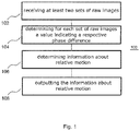
- Fig. 1 illustrates a flowchart of a method 100 for determining relative motion between a ToF camera and an object in a scene sensed by the ToF camera.
- Fig. 2 Prior to describing method 100 in detail, some basics of conventional ToF depth measurement will introductorily be described in the following paragraphs for pedagogical reasons with respect to Fig. 2 .
- a ToF camera 200 comprises an illumination element 210 for illuminating the scene with modulated light 211 (e.g. infrared light).
- the illumination element 210 generates the modulated light 211 based on a (electric) modulated reference signal such as a continuous wave modulated signal (e.g. by controlling one or more Light-Emitting Diodes, LEDs, or one or more laser diodes based on the modulated reference signal).
- An object 230 in the scene that is illuminated by the modulated light 211 reflects at least part of the modulated light 211 back to a light capturing element 220 (e.g. comprising optics, an image sensor and driver electronics) of the ToF camera 200.
- the light capturing element 220 receives reflected light from the object 230.
- the image sensor of the light capturing element 220 is pixelated and each pixel measures a fraction of the reflected light. Accordingly, (electric) measurement signals based on the reflected light from the scene are generated.
- each pixel may comprise a Photonic Mixer Device (PMD) for measuring the reflected light.
- PMD Photonic Mixer Device
- the reflected light exhibits a delay with respect to the emission of the modulated light 211. Accordingly, the measurement signals experience distance dependent (depth dependent) phase shifts with respect to the modulated reference signal.
- the modulated reference signal and the measurement signal of the respective pixel are correlated according to a (auto)correlation function c ( ⁇ + ⁇ d ) in order to obtain a correlation value L for each pixel.
- the correlation function c ( ⁇ + ⁇ d ) mimics a phase-distance function describing the relation between the distance d obj and the phase between the modulated reference signal and the measurement signal.
- the output of the correlation function c ( ⁇ + ⁇ d ) is the correlation value L for each pixel.
- the determined correlation values L are then combined to a raw image (sometimes also referred to as "phase image"). That is, the raw image comprises a plurality of pixels each representing a corresponding correlation value L.
- Each of the correlation values indicates a respective phase difference between the reflected light (represented by the respective measurement signal) and the modulated reference signal. For example, if PMDs are used for measuring the reflected light, the steps of generating the measurement signals and correlating the measurement signals with the modulated reference signal may be combined to a single step.
- phase offset ⁇ between the modulated reference signal and the measurement signals as used for the correlations varies between the individual raw images.
- different phase offsets ⁇ are used for correlating the modulated signal and the measurement signals in order to obtain the individual raw images.
- phase offsets of 0°, 90°, 180° and 270° may be used to generate four raw images each comprising a plurality of pixels that represent corresponding correlation values L 0° , L 90° , L 180° and L 270° .
- the correlation function c ( ⁇ + ⁇ d ) is shifted by the distance dependent phase shift ⁇ d between the measurement signal and the modulated reference signal of the pixel with respect to the zero value of the function's argument.
- the object 230 actively emits a modulated light 231 in method 100 - the ToF camera 200 does not illuminate the scene for determining relative motion between the ToF camera 200 and the object 230. That is, the light received by the capturing element 220 of the ToF camera is the modulated light 231 which is actively emitted by the object 230.
- the modulated light 231 may, e.g., be an infrared signal, which is emitted by one or more LEDs or laser diodes of the object 230.
- Method 100 comprises receiving at least two sets of raw images of the scene comprising the object 230 from the ToF camera 200.
- the at least two sets of raw images each comprise at least one raw image.
- each of the received sets of raw images comprises one or more raw images (e.g. 2, 4, 8, or 16 raw images).
- the raw images are based on correlations of the modulated reference signal and the measurement signals of the capturing element 220 of the ToF camera 200. Accordingly, the measurement signals are based on the modulated light signal 231 emitted by the object 230. Therefore, the (correlation) values represented by the pixels of the one or more raw images of each set of raw images indicate a respective phase difference the modulated light signal and the modulated reference signal.
- phase images with phase offsets ⁇ of 0° and 90° may be taken, or four phase images with equidistant phase offset ⁇ may be taken.
- the time difference(s) between the capture times of the individual raw images within the respective sets of raw images may be smaller than a time difference between two immediately succeeding raw images belonging to different sets of raw images (e.g. a last raw image of a first set of raw images and the first raw image of a immediately following second set of raw images). Accordingly, the sets of raw images characterize positions of the object 230 relative to the ToF camera at different time instances.
- method 100 comprises determining 104 for each set of raw images a value indicating a respective phase difference between the modulated light signal and the modulated reference signal based on the respective set of raw images. That is, for the first set of raw images of the at least two sets of raw images, a first value indicating a first phase difference between the modulated light signal and the modulated reference signal is determined based on only the one or more raw images of the first set of raw images, whereas for the second set of raw images of the at least two sets of raw images, a second value indicating a second phase difference between the modulated light signal and the modulated reference signal is determined based on only the one or more raw images of the second set of raw images.
- the step of determining 104 a respective value indicating the phase difference between the modulated light signal and the modulated reference signal for one of the at least two sets of raw images may, e.g., comprise applying a calibration correction and/or an error correction to the values indicated by the pixels of the one or more raw images of the respective set of raw images.
- the one or more raw images of the respective set of raw images may be corrected for fixed patterns, temperature variations, wiggling, etc.
- the step of determining 104 a respective value indicating the phase difference between the modulated light signal and the modulated reference signal for the one set of raw images may alternatively or additionally comprise combining the phase information contained in the individual raw images of the one set of raw images.
- the value indicating the phase difference between the modulated light signal and the modulated reference signal may be determined according to above expression (1), wherein the correlation values in expression (1) may be the unmodified correlation values of the raw images or be calibration and/or error corrected correlation values.
- Method 100 additionally comprises determining 106 information about relative motion between the ToF camera 200 and the object 230 based on the values indicating the phase differences.
- the ToF camera continuously captures the phase difference by capturing sets of single or multiple raw images.
- the information about relative motion between the ToF camera 200 and the object 230 may indicate at least one of the relative distance change ⁇ d obj or the relative speed ⁇ v obj between the ToF camera 200 and the object 230.
- method 100 comprises outputting 108 the information about relative motion between the ToF camera 200 and the object 230.
- an image comprising a plurality of pixels that indicate the motion between the ToF camera 200 and the object 230 may be output.
- a stream or an array of values indicating the motion between the ToF camera 200 and the object 230 may be output.
- Method 100 may enable to measure relative motion (e.g. relative distance changes) between the ToF camera 200 and the modulated light source 230.
- method 100 uses the ToF camera 200 and the object 230 in a cooperative manner by equipping the object 230 with an active illumination unit.
- the ToF camera 200 is able to sample the modulated light signal 231 of the cooperative object 230 over wide distance ranges with shorter exposure times compared to conventional ToF depth sensing. Since the ToF camera 200 does not need to emit light, the sample rate may be improved (increased) without regards to eye-safety.
- method 100 in its most basic implementations may not allow to determine an absolute distance between the ToF camera 200 and the object 230, it may allow to measure relative motion between the ToF camera 200 and the object 230.
- method 100 additionally comprises controlling the ToF camera 200 to synchronize the modulation frequency of the modulated reference signal to the modulation frequency of the modulated light signal 231 emitted by the object 230.
- the ToF camera uses a synchronization mechanism to approximate its pixel modulation clock to the frequency of the modulated light signal 231 emitted by the object 230.
- a phasor (also known as phase vector) is a complex number representing a ToF measurement.
- the phasor consists of an angle describing the (depth/distance dependent) phase shift of a measurement signal measured by the ToF camera's light capturing element with respect to the modulated reference signal. Further, the phasor consists of a length describing the intensity of the measurement signal, i.e. the measured intensity of the measured light. Since the angle of the phase is depth/distance dependent, sensing an object at different distances with respect to the ToF camera rotates the phasor.
- the left part of Fig. 3 illustrates the phasor p 1 for a first set of raw images.
- the phasor p 1 exhibits an intensity I 1 and an angle ⁇ 1 .
- the right part of Fig. 3 illustrates the phasor p 2 for a consecutive second set of raw images.
- the phasor p 2 exhibits an intensity I 2 and an angle ⁇ 2 .
- the time span ⁇ t lapses between the capture of the first set of raw images and the capture of the second set of raw images.
- movement of the object 230 causes the phasor to rotate.
- the synchronization error of the modulation frequency of the modulated reference signal used by the ToF camera 200 with respect to the modulation frequency of the modulated light signal 231 emitted by the object 230 causes the phasor to rotate.
- ⁇ 2 ⁇ 1 + ⁇ d + ⁇ e with ⁇ d denoting the phase shift caused by the relative motion between the ToF camera 200 and the object 230, and ⁇ e denoting the phase shift caused by the synchronization error of the modulation frequency of the modulated reference signal used by the ToF camera 200.
- method 100 further comprises modifying the values indicating the phase differences based on the synchronization error f error of the modulation frequency of the modulated reference signal with respect to the modulation frequency of the modulated light signal 231 emitted by the object 230. That is, compensated (synchronization error corrected) values indicating the phase differences are obtained so that the phase drift caused by the synchronization error f error may be compensated (corrected) after each measurement (for obtaining a set of raw images).
- the information about relative motion between the ToF camera 200 and the object 230 is accordingly determined based on the compensated values.
- Synchronizing the modulation frequency of the modulated reference signal to the modulation frequency of the modulated light signal 231 emitted by the object 230 may be done in many different ways. In the following, some exemplary options for synchronization will be described. However, the proposed technique is not restricted to the following examples.
- the modulation frequency of the modulated reference signal may be synchronized with the modulation frequency of the modulated light signal 231 emitted by the object 230 according to method described in document DE 10 2017 105 142 A1 which is hereby incorporated by reference.
- method 100 may comprise controlling the ToF camera 200 to synchronize the modulation frequency of the modulated reference signal to a Radio Frequency (RF) signal receivable by the ToF camera 200 and the object 230.
- RF Radio Frequency
- both systems may synchronize their reference frequencies to the phase of a commonly available RF signal such as a mobile communications signal (e.g. according to a 3rd Generation Partnership Project, 3GPP, standard) or a Global Navigation Satellite System (GNSS) signal such as a Global Positioning System (GPS) signal.
- a mobile communications signal e.g. according to a 3rd Generation Partnership Project, 3GPP, standard
- GNSS Global Navigation Satellite System
- GPS Global Positioning System
- the ToF camera 200 may provide an RF synchronization signal to the object 230, or vice versa. That is, method 100 may, in some examples, comprise controlling the ToF camera 200 to synchronize the modulation frequency of the modulated reference signal to a RF reference signal, and controlling the ToF camera 200 to transmit the RF reference signal to the object 230. In other examples, method 100 may comprise controlling the ToF camera 200 to receive a RF reference signal from the object 230, and controlling the ToF camera 200 to synchronize the modulation frequency of the modulated reference signal to the received RF reference signal.
- Method 100 may further comprise determining the synchronization error f error of the modulation frequency of the modulated reference signal based on a first auxiliary set of raw images of the scene.
- the raw images of the first auxiliary set of raw images are captured using the same modulated reference signal (i.e. a constant reference phase for the pixels of the light capturing element).
- Respective first signal strengths for the modulated light signal 231 emitted by the object 230 are determined in the individual raw images of the first auxiliary set of raw images.
- a first waveform is determined using the respective first signal strengths for the modulated light signal 231 as samples of the first waveform.
- the average signal value of the light source 230 is extracted from each image of the first auxiliary set of raw images and used as a sample to estimate the synchronization error f error . That is, the average signal of the object 230 on the pixel array of the light capturing element 220 is put into a waveform. Further, determining the synchronization error f error comprises determining a frequency of the first waveform as the synchronization error f error of the modulation frequency of the modulated reference signal 231. In other words, the frequency of the waveform determined by average signal values of the object 230 is the synchronization error f error .
- each raw image of the first auxiliary set of raw images may comprise less pixels than the raw images of the first and/or second set of raw images used for determining the relative motion.
- the frequency of the modulated reference signal is changed by a predetermined positive frequency step and another series of raw images may be captured.
- determining the synchronization error f error further comprises determining respective second signal strengths for the modulated light signal 231 in the individual raw images of a second auxiliary set of raw images of the scene.
- the raw images of the first and second auxiliary sets of raw images are based on correlations of measurement signals of the ToF camera with two different modulated reference signals which exhibit different modulation frequencies.
- determining the synchronization error f error comprises determining a second waveform using the respective second signal strengths for the modulated light signal as samples of the second waveform, and determining a frequency of the second waveform.
- a sign of the synchronization error f error of the modulation frequency of the modulated reference signal is determined based on a comparison of the frequencies of the first waveform and the second waveform. For example, if the frequency of the second waveform is higher than the frequency of the first waveform, the sign of the synchronization error f error may be determined as positive, and vice versa.
- the modulated reference signal may be reset to the original frequency.
- Method 100 may further be used to extrapolate a known absolute distance between the ToF camera 200 and the object 230.
- method 100 may further comprise receiving information about an absolute distance between the ToF camera 200 and the object 230.
- Method 100 may comprise updating the information about an absolute distance between the ToF camera 200 and the object 230 based on the determined information about relative motion between the ToF camera 200 and the object 230.
- the object may transmit the information about the absolute distance between the ToF camera 200 and the object 230 to the ToF camera 200.
- an element comprising / holding the ToF camera 200 may transmit the information about an absolute distance between the ToF camera 200 and the object 230 to the ToF camera 200.
- the information may, e.g., be transmitted to the ToF camera using RF communication or optical communication.
- the information about the absolute distance between the ToF camera 200 and the object 230 may be encoded into the modulated light signal emitted by the object 230. In other words, the relative motion determination may be combined with optical communication.
- the modulated light signal 231 emitted by the object 230 may be modulated with the information about the absolute distance between the ToF camera 200 and the object 230 by means of Phase-Shift Keying (PSK).
- PSK Phase-Shift Keying
- the ToF camera 200 is able to observe the phase differences used for determining the relative motion in PSK modulated optical signals.
- method 100 may comprise controlling the ToF camera 200 to determine the information about the absolute distance between the ToF camera 200 and the object 230 by illuminating the scene (using the modulated reference signal). Accordingly, the information about the absolute distance between the ToF camera 200 and the object 230 is again updated based on the information about the absolute distance between the ToF camera 200 and the object 230.
- the ToF camera 200 is controlled to illuminate the scene while the object 230 pauses emitting the modulated light signal 231 so that the conventional ToF depth measurement is not influenced / disturbed by the modulated light signal 231.
- the cooperative object 230 pauses its modulated light signal 231 for, e.g., certain intervals to allow the ToF camera 200 to measure the absolute distance. After the absolute distance is determined, the relative measurements may be used to extrapolate the absolute distance. Accordingly, the amount of light emitted by the ToF camera 200 may be reduced.
- the proposed technique may, e.g., be used between vehicles in traffic as a redundant high frequency distance estimator. Further, the proposed technique may be used in a control loop for regulating the distance between the vehicles. If the proposed system is only synchronized by the ToF sensor synchronization methods as described above, both speed and distance are relative to the beginning of the proposed phase tracking procedure.
- the active illumination of one of the vehicles may therefore transmit its current speed or distance via the emitted light(pulses). If the other car is within the range of the other vehicle's ToF camera, the ToF camera of the other vehicle may conduct reference depth measurements to derive the absolute speed or distance of the vehicle and extrapolate it according to the proposed technique.
- the proposed technique may, e.g., be used for motion tracking or indoor localization systems.
- the proposed technique may allow to extrapolate absolute measurements by relative measurements so that high localization update rates may be achieved.
- a vector may be determined and output that points into the direction of the current object movement. If the object 230 is localized in three dimensions, the motion of the object 230 may be predicted.
- the apparatus 400 comprises a processing circuit 420.
- the processing circuit 420 may be a single dedicated processor, a single shared processor, or a plurality of individual processors, some of which or all of which may be shared, a digital signal processor (DSP) hardware, an application specific integrated circuit (ASIC) or a field programmable gate array (FPGA).
- DSP digital signal processor
- ASIC application specific integrated circuit
- FPGA field programmable gate array
- the processing circuit 420 may optionally be coupled to, e.g., read only memory (ROM) for storing software, random access memory (RAM) and/or non-volatile memory.
- the apparatus 400 may further comprise other hardware - conventional and/or custom.
- the apparatus 400 comprises an input circuit 410 configured to receive input data 401 representing the at least two sets of raw images of the scene from the ToF camera.
- the processing circuit 420 processes the input data 401 according to the above described concept for determining relative motion between the ToF camera and the object.
- an output circuit 430 of the apparatus outputs output data 402 representing the information about relative motion between the ToF camera and the object.
- apparatus 400 may be implemented in an application processor coupled to a ToF camera module providing the at least two sets of raw images or in the ToF camera module itself.
- Some examples relate to a method for determining relative motion between a ToF camera and an object in a scene sensed by the ToF camera.
- the object emits a modulated light signal.
- the method comprises receiving at least two sets of raw images of the scene from the ToF camera.
- the at least two sets of raw images each comprise at least one raw image.
- the raw images are based on correlations of a modulated reference signal and measurement signals of the ToF camera.
- the measurement signals are based on the modulated light signal emitted by the object.
- the method comprises determining for each set of raw images a value indicating a respective phase difference between the modulated light signal and the modulated reference signal based on the respective set of raw images.
- the method additionally comprises determining information about relative motion between the ToF camera and the object based on the values indicating the phase differences. Further, the method comprises outputting the information about relative motion between the ToF camera and the object.
- the method further comprises controlling the ToF camera to synchronize a modulation frequency of the modulated reference signal to a modulation frequency of the modulated light signal emitted by the object. Additionally, the method comprises modifying the values indicating the phase differences based on a synchronization error of the modulation frequency of the modulated reference signal to obtain compensated values. The information about relative motion between the ToF camera and the object is determined based on the compensated values.
- controlling the ToF camera to synchronize the modulation frequency of the modulated reference signal to the modulation frequency of the modulated light signal emitted by the object comprises controlling the ToF camera to synchronize the modulation frequency of the modulated reference signal to a RF signal receivable by the ToF camera and the object.
- controlling the ToF camera to synchronize the modulation frequency of the modulated reference signal to the modulation frequency of the modulated light signal emitted by the object comprises: controlling the ToF camera to synchronize the modulation frequency of the modulated reference signal to a RF reference signal; and controlling the ToF camera to transmit the RF reference signal to the object.
- controlling the ToF camera to synchronize the modulation frequency of the modulated reference signal to the modulation frequency of the modulated light signal emitted by the object comprises: controlling the ToF camera to receive a RF reference signal from the object; and controlling the ToF camera to synchronize the modulation frequency of the modulated reference signal to the RF reference signal.
- the method further comprises determining the synchronization error of the modulation frequency of the modulated reference signal based on a first auxiliary set of raw images of the scene.
- determining the synchronization error of the modulation frequency of the modulated reference signal comprises: determining respective first signal strengths for the modulated light signal in the individual raw images of the first auxiliary set of raw images; determining a first waveform using the respective first signal strengths for the modulated light signal as samples of the first waveform; and determining a frequency of the first waveform as the synchronization error of the modulation frequency of the modulated reference signal.
- determining the synchronization error of the modulation frequency of the modulated reference signal further comprises: determining respective second signal strengths for the modulated light signal in the individual raw images of a second auxiliary set of raw images of the scene, wherein the raw images of the first and second auxiliary sets of raw images are based on correlations of measurement signals of the ToF camera with two different modulated reference signals; determining a second waveform using the respective second signal strengths for the modulated light signal as samples of the second waveform; determining a frequency of the second waveform; and determining a sign of the synchronization error of the modulation frequency of the modulated reference signal based on a comparison of the frequencies of the first waveform and the second waveform.
- the two different modulated reference signals exhibit, according to some examples, different modulation frequencies.
- the method further comprises: receiving information about an absolute distance between the ToF camera and the object; and updating the information about an absolute distance between the ToF camera and the object based on the information about relative motion between the ToF camera and the object.
- the information about the absolute distance between the ToF camera and the object is encoded into the modulated light signal emitted by the object.
- the method further comprises: controlling the ToF camera to determine information about an absolute distance between the ToF camera and the object by illuminating the scene; and updating the information about the absolute distance between the ToF camera and the object based on the information about relative motion between the ToF camera and the object.
- the ToF camera is controlled to illuminate the scene while the object pauses emitting the modulated light signal.
- the information about relative motion between the ToF camera and the object indicates at least one of a relative distance change or a relative speed between the ToF camera and the object.
- the apparatus comprises an input circuit configured to receive multiple sets of raw images of the scene from the ToF camera.
- the at least two sets of raw images each comprise at least one raw image.
- the raw images are based on correlations of a modulated reference signal and measurement signals of the ToF camera.
- the measurement signals are based on the modulated light signal emitted by the object.
- the apparatus additionally comprises a processing circuit configured to determine for each set of raw images a value indicating a respective phase difference between the modulated light signal and the modulated reference signal based on the respective set of raw images.
- the processing circuit is additionally configured to determine information about relative motion between the ToF camera and the object based on the values indicating the phase differences.
- the apparatus comprises an output circuit configured to output the information about relative motion between the ToF camera and the object.
- the apparatus comprises means for receiving multiple sets of raw images of the scene from the ToF camera.
- the at least two sets of raw images each comprise at least one raw image.
- the raw images are based on correlations of a modulated reference signal and measurement signals of the ToF camera.
- the measurement signals are based on the modulated light signal emitted by the object.
- the apparatus comprises means for determining for each set of raw images a value indicating a respective phase difference between the modulated light signal and the modulated reference signal based on the respective set of raw images.
- the apparatus additionally comprises means for determining information about relative motion between the ToF camera and the object based on the values indicating the phase differences. Further, the apparatus comprises means for outputting the information about relative motion between the ToF camera and the object.
- Examples relate to a non-transitory machine readable medium having stored thereon a program having a program code for performing the method for determining relative motion between a ToF camera and an object in a scene sensed by the ToF camera as described herein, when the program is executed on a processor or a programmable hardware.
- Other examples relate to a program having a program code for performing the method for determining relative motion between a ToF camera and an object in a scene sensed by the ToF camera as described herein, when the program is executed on a processor or a programmable hardware.
- Examples according to the proposed concept may allow to measure the relative distance to a modulated light source with ToF sensors.
- Using the modulated light source as object may allow to capture relative distance changes at longer distance ranges with higher sample rates for the ToF sensors.
- a block diagram may, for instance, illustrate a high-level circuit diagram implementing the principles of the disclosure.
- a flow chart, a flow diagram, a state transition diagram, a pseudo code, and the like may represent various processes, operations or steps, which may, for instance, be substantially represented in computer readable medium and so executed by a computer or processor, whether or not such computer or processor is explicitly shown.
- Methods disclosed in the specification or in the claims may be implemented by a device having means for performing each of the respective acts of these methods.
- each claim may stand on its own as a separate example. While each claim may stand on its own as a separate example, it is to be noted that - although a dependent claim may refer in the claims to a specific combination with one or more other claims - other examples may also include a combination of the dependent claim with the subject matter of each other dependent or independent claim. Such combinations are explicitly proposed herein unless it is stated that a specific combination is not intended. Furthermore, it is intended to include also features of a claim to any other independent claim even if this claim is not directly made dependent to the independent claim.
Landscapes
- Engineering & Computer Science (AREA)
- Physics & Mathematics (AREA)
- General Physics & Mathematics (AREA)
- Electromagnetism (AREA)
- Radar, Positioning & Navigation (AREA)
- Remote Sensing (AREA)
- Computer Networks & Wireless Communication (AREA)
- Computer Vision & Pattern Recognition (AREA)
- Theoretical Computer Science (AREA)
- Multimedia (AREA)
- Optics & Photonics (AREA)
- Signal Processing (AREA)
- Studio Devices (AREA)
- Optical Radar Systems And Details Thereof (AREA)
- Length Measuring Devices By Optical Means (AREA)
Abstract
Description
- Examples relate to Time-of-Flight (ToF) sensing. In particular, examples relate to a method and an apparatus for determining relative motion between a ToF camera and an object in a scene sensed by the ToF camera.
- In various applications, ToF sensors measure distances to electronic devices. ToF sensors are limited in range and image (frame) rate, which limits the ToF sensors capability to sense motion of an object relative to the ToF sensor.
- Hence, there may be a demand for an improved technique for determining relative motion between a ToF camera and an object.
- The demand may be satisfied by the subject matter of the appended claims.
- An example relates to a method for determining relative motion between a ToF camera and an object in a scene sensed by the ToF camera. The object emits a modulated light signal. The method comprises receiving at least two sets of raw images of the scene from the ToF camera. The raw images are based on correlations of a modulated reference signal and measurement signals of the ToF camera. The at least two sets of raw images each comprise at least one raw image. The measurement signals are based on the modulated light signal emitted by the object. Further, the method comprises determining for each set of raw images a value indicating a respective phase difference between the modulated light signal and the modulated reference signal based on the respective set of raw images. The method additionally comprises determining information about relative motion between the ToF camera and the object based on the values indicating the phase differences. Further, the method comprises outputting the information about relative motion between the ToF camera and the object.
- Another example relates to an apparatus for determining relative motion between a ToF camera and an object in a scene sensed by the ToF camera. The object emits a modulated light signal. The apparatus comprises an input circuit configured to receive multiple sets of raw images of the scene from the ToF camera. The at least two sets of raw images each comprise at least one raw image. The raw images are based on correlations of a modulated reference signal and measurement signals of the ToF camera. The measurement signals are based on the modulated light signal emitted by the object. The apparatus additionally comprises a processing circuit configured to determine for each set of raw images a value indicating a respective phase difference between the modulated light signal and the modulated reference signal based on the respective set of raw images. The processing circuit is additionally configured to determine information about relative motion between the ToF camera and the object based on the values indicating the phase differences. Further, the apparatus comprises an output circuit configured to output the information about relative motion between the ToF camera and the object.
- Some examples of apparatuses and/or methods will be described in the following by way of example only, and with reference to the accompanying figures, in which
-
Fig. 1 illustrates a flowchart of an example of a method for determining relative motion between a ToF camera and an object in a scene sensed by the ToF camera; -
Fig. 2 illustrates an example of a ToF camera sensing an object; -
Fig. 3 illustrates two exemplary phasors; and -
Fig. 4 illustrates an example of an apparatus for determining relative motion between a ToF camera and an object in a scene sensed by the ToF camera. - Various examples will now be described more fully with reference to the accompanying drawings in which some examples are illustrated. In the figures, the thicknesses of lines, layers and/or regions may be exaggerated for clarity.
- Accordingly, while further examples are capable of various modifications and alternative forms, some particular examples thereof are shown in the figures and will subsequently be described in detail. However, this detailed description does not limit further examples to the particular forms described. Further examples may cover all modifications, equivalents, and alternatives falling within the scope of the disclosure. Same or like numbers refer to like or similar elements throughout the description of the figures, which may be implemented identically or in modified form when compared to one another while providing for the same or a similar functionality.
- It will be understood that when an element is referred to as being "connected" or "coupled" to another element, the elements may be directly connected or coupled via one or more intervening elements. If two elements A and B are combined using an "or", this is to be understood to disclose all possible combinations, i.e. only A, only B as well as A and B, if not explicitly or implicitly defined otherwise. An alternative wording for the same combinations is "at least one of A and B" or "A and/or B". The same applies, mutatis mutandis, for combinations of more than two Elements.
- The terminology used herein for the purpose of describing particular examples is not intended to be limiting for further examples. Whenever a singular form such as "a", "an" and "the" is used and using only a single element is neither explicitly or implicitly defined as being mandatory, further examples may also use plural elements to implement the same functionality. Likewise, when a functionality is subsequently described as being implemented using multiple elements, further examples may implement the same functionality using a single element or processing entity. It will be further understood that the terms "comprises", "comprising", "includes" and/or "including", when used, specify the presence of the stated features, integers, steps, operations, processes, acts, elements and/or components, but do not preclude the presence or addition of one or more other features, integers, steps, operations, processes, acts, elements, components and/or any group thereof.
- Unless otherwise defined, all terms (including technical and scientific terms) are used herein in their ordinary meaning of the art to which the examples belong.
-
Fig. 1 illustrates a flowchart of amethod 100 for determining relative motion between a ToF camera and an object in a scene sensed by the ToF camera. Prior to describingmethod 100 in detail, some basics of conventional ToF depth measurement will introductorily be described in the following paragraphs for pedagogical reasons with respect toFig. 2 . - A
ToF camera 200 comprises an illumination element 210 for illuminating the scene with modulated light 211 (e.g. infrared light). The illumination element 210 generates the modulatedlight 211 based on a (electric) modulated reference signal such as a continuous wave modulated signal (e.g. by controlling one or more Light-Emitting Diodes, LEDs, or one or more laser diodes based on the modulated reference signal). Anobject 230 in the scene that is illuminated by themodulated light 211 reflects at least part of the modulatedlight 211 back to a light capturing element 220 (e.g. comprising optics, an image sensor and driver electronics) of theToF camera 200. In other words, in conventional ToF sensing, the light capturingelement 220 receives reflected light from theobject 230. - The image sensor of the light capturing
element 220 is pixelated and each pixel measures a fraction of the reflected light. Accordingly, (electric) measurement signals based on the reflected light from the scene are generated. For example, each pixel may comprise a Photonic Mixer Device (PMD) for measuring the reflected light. - Depending on the distance dobj between the
ToF camera 200 and theobject 230, i.e. depending on the depth, the reflected light exhibits a delay with respect to the emission of the modulatedlight 211. Accordingly, the measurement signals experience distance dependent (depth dependent) phase shifts with respect to the modulated reference signal. - The modulated reference signal and the measurement signal of the respective pixel are correlated according to a (auto)correlation function c(δ + ϕd ) in order to obtain a correlation value L for each pixel. The correlation function c(δ + ϕd ) mimics a phase-distance function describing the relation between the distance dobj and the phase between the modulated reference signal and the measurement signal.
- The output of the correlation function c(δ + ϕd ) is the correlation value L for each pixel. The determined correlation values L are then combined to a raw image (sometimes also referred to as "phase image"). That is, the raw image comprises a plurality of pixels each representing a corresponding correlation value L. Each of the correlation values indicates a respective phase difference between the reflected light (represented by the respective measurement signal) and the modulated reference signal. For example, if PMDs are used for measuring the reflected light, the steps of generating the measurement signals and correlating the measurement signals with the modulated reference signal may be combined to a single step.
- In order to sample the correlation function c(δ + ϕd ), plural raw images are generated. A phase offset δ between the modulated reference signal and the measurement signals as used for the correlations varies between the individual raw images. In other words, different phase offsets δ are used for correlating the modulated signal and the measurement signals in order to obtain the individual raw images.
- Sampling the same object at the same distance and exhibiting the same reflectivity enables to sample the correlation function c(δ + ϕd ). For example, phase offsets of 0°, 90°, 180° and 270° may be used to generate four raw images each comprising a plurality of pixels that represent corresponding correlation values L 0°, L 90°, L 180° and L 270°.
- For the correlation value L 0°, the correlation function c(δ + ϕd ) is shifted by the distance dependent phase shift ϕd between the measurement signal and the modulated reference signal of the pixel with respect to the zero value of the function's argument.
- Using the four correlation values L 0°, L 90°, L 180° and L 270° that sample the correlation function c(δ + ϕd ), the phase shift (phase angle) ϕd may be determined as follows:

- Taking into account the speed of light c and the modulation frequency fp of the emitted light 211 (i.e. the modulation frequency of the modulated reference signal), the distance dobj to the
object 230, i.e. the depth, may be calculated as follows:
- In contrast to conventional ToF depth sensing as described above, the
object 230 actively emits a modulated light 231 in method 100 - theToF camera 200 does not illuminate the scene for determining relative motion between theToF camera 200 and theobject 230. That is, the light received by the capturingelement 220 of the ToF camera is the modulated light 231 which is actively emitted by theobject 230. The modulatedlight 231 may, e.g., be an infrared signal, which is emitted by one or more LEDs or laser diodes of theobject 230. -
Method 100 comprises receiving at least two sets of raw images of the scene comprising theobject 230 from theToF camera 200. The at least two sets of raw images each comprise at least one raw image. In other words, each of the received sets of raw images comprises one or more raw images (e.g. 2, 4, 8, or 16 raw images). Similar to what is described above, the raw images are based on correlations of the modulated reference signal and the measurement signals of the capturingelement 220 of theToF camera 200. Accordingly, the measurement signals are based on the modulatedlight signal 231 emitted by theobject 230. Therefore, the (correlation) values represented by the pixels of the one or more raw images of each set of raw images indicate a respective phase difference the modulated light signal and the modulated reference signal. For example, two phase images with phase offsets δ of 0° and 90° may be taken, or four phase images with equidistant phase offset δ may be taken. The time difference(s) between the capture times of the individual raw images within the respective sets of raw images may be smaller than a time difference between two immediately succeeding raw images belonging to different sets of raw images (e.g. a last raw image of a first set of raw images and the first raw image of a immediately following second set of raw images). Accordingly, the sets of raw images characterize positions of theobject 230 relative to the ToF camera at different time instances. - Further,
method 100 comprises determining 104 for each set of raw images a value indicating a respective phase difference between the modulated light signal and the modulated reference signal based on the respective set of raw images. That is, for the first set of raw images of the at least two sets of raw images, a first value indicating a first phase difference between the modulated light signal and the modulated reference signal is determined based on only the one or more raw images of the first set of raw images, whereas for the second set of raw images of the at least two sets of raw images, a second value indicating a second phase difference between the modulated light signal and the modulated reference signal is determined based on only the one or more raw images of the second set of raw images. - The step of determining 104 a respective value indicating the phase difference between the modulated light signal and the modulated reference signal for one of the at least two sets of raw images may, e.g., comprise applying a calibration correction and/or an error correction to the values indicated by the pixels of the one or more raw images of the respective set of raw images. For example, the one or more raw images of the respective set of raw images may be corrected for fixed patterns, temperature variations, wiggling, etc.
- If one of the sets of raw images comprises more than one raw image, the step of determining 104 a respective value indicating the phase difference between the modulated light signal and the modulated reference signal for the one set of raw images may alternatively or additionally comprise combining the phase information contained in the individual raw images of the one set of raw images. For example, the value indicating the phase difference between the modulated light signal and the modulated reference signal may be determined according to above expression (1), wherein the correlation values in expression (1) may be the unmodified correlation values of the raw images or be calibration and/or error corrected correlation values.
-
Method 100 additionally comprises determining 106 information about relative motion between theToF camera 200 and theobject 230 based on the values indicating the phase differences. - In other words, the ToF camera continuously captures the phase difference by capturing sets of single or multiple raw images. Changes in the phase difference can be translated to relative motion taking into account the speed of light c and the modulation frequency fp of the modulated reference signal:

ToF camera 200 and theobject 230 between the capture times of the two consecutive sets of raw images. - Similarly, a relative motion speed Δvobj between the
ToF camera 200 and theobject 230 may be determined:
- Therefore, the information about relative motion between the
ToF camera 200 and theobject 230 may indicate at least one of the relative distance change Δdobj or the relative speed Δvobj between theToF camera 200 and theobject 230. - Further,
method 100 comprises outputting 108 the information about relative motion between theToF camera 200 and theobject 230. For example, an image comprising a plurality of pixels that indicate the motion between theToF camera 200 and theobject 230 may be output. Alternatively or additionally, a stream or an array of values indicating the motion between theToF camera 200 and theobject 230 may be output. -
Method 100 may enable to measure relative motion (e.g. relative distance changes) between theToF camera 200 and the modulatedlight source 230. In other words,method 100 uses theToF camera 200 and theobject 230 in a cooperative manner by equipping theobject 230 with an active illumination unit. TheToF camera 200 is able to sample the modulatedlight signal 231 of thecooperative object 230 over wide distance ranges with shorter exposure times compared to conventional ToF depth sensing. Since theToF camera 200 does not need to emit light, the sample rate may be improved (increased) without regards to eye-safety. Even thoughmethod 100 in its most basic implementations may not allow to determine an absolute distance between theToF camera 200 and theobject 230, it may allow to measure relative motion between theToF camera 200 and theobject 230. - In order to be able to correctly determine the respective values indicating the phase differences, the modulation frequency of the modulated reference signal used by the
light capturing element 220 of theToF camera 200 is to be synchronized to a modulation frequency of the modulatedlight signal 231 emitted by theobject 230. Therefore,method 100 additionally comprises controlling theToF camera 200 to synchronize the modulation frequency of the modulated reference signal to the modulation frequency of the modulatedlight signal 231 emitted by theobject 230. In other words, the ToF camera uses a synchronization mechanism to approximate its pixel modulation clock to the frequency of the modulatedlight signal 231 emitted by theobject 230. - Perfect synchronization is not possible in practice so that the modulation frequencies of the modulated reference signal used by the
ToF camera 200 and the modulatedlight signal 231 emitted by theobject 230 may differ (e.g. by a few Hz). For being able to measure relative distance changes, the synchronization error needs to be compensated. This is exemplarily illustrated inFig. 3 depicting the phasors p1 and p2 for two consecutive sets of raw images. - A phasor (also known as phase vector) is a complex number representing a ToF measurement. The phasor consists of an angle describing the (depth/distance dependent) phase shift of a measurement signal measured by the ToF camera's light capturing element with respect to the modulated reference signal. Further, the phasor consists of a length describing the intensity of the measurement signal, i.e. the measured intensity of the measured light. Since the angle of the phase is depth/distance dependent, sensing an object at different distances with respect to the ToF camera rotates the phasor.
- The left part of
Fig. 3 illustrates the phasor p 1 for a first set of raw images. The phasor p 1 exhibits an intensity I 1 and an angle ϕ 1. The right part ofFig. 3 illustrates the phasor p 2 for a consecutive second set of raw images. The phasor p 2 exhibits an intensity I 2 and an angle ϕ 2. - The time span Δt lapses between the capture of the first set of raw images and the capture of the second set of raw images. As described above, movement of the
object 230 causes the phasor to rotate. Further, the synchronization error of the modulation frequency of the modulated reference signal used by theToF camera 200 with respect to the modulation frequency of the modulatedlight signal 231 emitted by theobject 230 causes the phasor to rotate. In terms of a mathematical expression, this may be expressed as follows:
ToF camera 200 and theobject 230, and ϕe denoting the phase shift caused by the synchronization error of the modulation frequency of the modulated reference signal used by theToF camera 200. - In order to obtain the correct phase ϕ 2,corr for the consecutive second set of raw images, the phase shift ϕe caused by the synchronization error (ϕe may, hence, be understood as a phase error) is to be subtracted from the measured phase ϕ 2:

- The phase error ϕe (e.g. in radiant) is caused by the synchronization error ferror (e.g. in Hz) and may be determined as follows:

- Therefore,
method 100 further comprises modifying the values indicating the phase differences based on the synchronization error ferror of the modulation frequency of the modulated reference signal with respect to the modulation frequency of the modulatedlight signal 231 emitted by theobject 230. That is, compensated (synchronization error corrected) values indicating the phase differences are obtained so that the phase drift caused by the synchronization error ferror may be compensated (corrected) after each measurement (for obtaining a set of raw images). - The information about relative motion between the
ToF camera 200 and theobject 230 is accordingly determined based on the compensated values. - Synchronizing the modulation frequency of the modulated reference signal to the modulation frequency of the modulated
light signal 231 emitted by theobject 230 may be done in many different ways. In the following, some exemplary options for synchronization will be described. However, the proposed technique is not restricted to the following examples. - In some examples, the modulation frequency of the modulated reference signal may be synchronized with the modulation frequency of the modulated
light signal 231 emitted by theobject 230 according to method described in documentDE 10 2017 105 142 A1 which is hereby incorporated by reference. - For example,
method 100 may comprise controlling theToF camera 200 to synchronize the modulation frequency of the modulated reference signal to a Radio Frequency (RF) signal receivable by theToF camera 200 and theobject 230. In other words, both systems may synchronize their reference frequencies to the phase of a commonly available RF signal such as a mobile communications signal (e.g. according to a 3rd Generation Partnership Project, 3GPP, standard) or a Global Navigation Satellite System (GNSS) signal such as a Global Positioning System (GPS) signal. - Alternatively, the
ToF camera 200 may provide an RF synchronization signal to theobject 230, or vice versa. That is,method 100 may, in some examples, comprise controlling theToF camera 200 to synchronize the modulation frequency of the modulated reference signal to a RF reference signal, and controlling theToF camera 200 to transmit the RF reference signal to theobject 230. In other examples,method 100 may comprise controlling theToF camera 200 to receive a RF reference signal from theobject 230, and controlling theToF camera 200 to synchronize the modulation frequency of the modulated reference signal to the received RF reference signal. - An exemplary technique for measuring the synchronization error ferror of the modulation frequency of the modulated reference signal is described in the following. However, it is to be noted that
method 100 is not limited to this technique. -
Method 100 may further comprise determining the synchronization error ferror of the modulation frequency of the modulated reference signal based on a first auxiliary set of raw images of the scene. The raw images of the first auxiliary set of raw images are captured using the same modulated reference signal (i.e. a constant reference phase for the pixels of the light capturing element). Respective first signal strengths for the modulatedlight signal 231 emitted by theobject 230 are determined in the individual raw images of the first auxiliary set of raw images. Further, a first waveform is determined using the respective first signal strengths for the modulatedlight signal 231 as samples of the first waveform. In other words, the average signal value of thelight source 230 is extracted from each image of the first auxiliary set of raw images and used as a sample to estimate the synchronization error ferror. That is, the average signal of theobject 230 on the pixel array of thelight capturing element 220 is put into a waveform. Further, determining the synchronization error ferror comprises determining a frequency of the first waveform as the synchronization error ferror of the modulation frequency of the modulatedreference signal 231. In other words, the frequency of the waveform determined by average signal values of theobject 230 is the synchronization error ferror. - To increase the sample rate, only a sub-image may be sampled by the
ToF camera 200. In other words, each raw image of the first auxiliary set of raw images may comprise less pixels than the raw images of the first and/or second set of raw images used for determining the relative motion. - For determining whether the synchronization error ferror exhibits a positive or a negative sign, the frequency of the modulated reference signal is changed by a predetermined positive frequency step and another series of raw images may be captured.
- In other words, determining the synchronization error ferror further comprises determining respective second signal strengths for the modulated
light signal 231 in the individual raw images of a second auxiliary set of raw images of the scene. The raw images of the first and second auxiliary sets of raw images are based on correlations of measurement signals of the ToF camera with two different modulated reference signals which exhibit different modulation frequencies. Further, determining the synchronization error ferror comprises determining a second waveform using the respective second signal strengths for the modulated light signal as samples of the second waveform, and determining a frequency of the second waveform. A sign of the synchronization error ferror of the modulation frequency of the modulated reference signal is determined based on a comparison of the frequencies of the first waveform and the second waveform. For example, if the frequency of the second waveform is higher than the frequency of the first waveform, the sign of the synchronization error ferror may be determined as positive, and vice versa. - Once the sign of the synchronization error ferror is determined, the modulated reference signal may be reset to the original frequency.
-
Method 100 may further be used to extrapolate a known absolute distance between theToF camera 200 and theobject 230. For example,method 100 may further comprise receiving information about an absolute distance between theToF camera 200 and theobject 230.Method 100 may comprise updating the information about an absolute distance between theToF camera 200 and theobject 230 based on the determined information about relative motion between theToF camera 200 and theobject 230. - For example, the object may transmit the information about the absolute distance between the
ToF camera 200 and theobject 230 to theToF camera 200. Alternatively, an element comprising / holding theToF camera 200 may transmit the information about an absolute distance between theToF camera 200 and theobject 230 to theToF camera 200. The information may, e.g., be transmitted to the ToF camera using RF communication or optical communication. In some examples, the information about the absolute distance between theToF camera 200 and theobject 230 may be encoded into the modulated light signal emitted by theobject 230. In other words, the relative motion determination may be combined with optical communication. For example, the modulatedlight signal 231 emitted by theobject 230 may be modulated with the information about the absolute distance between theToF camera 200 and theobject 230 by means of Phase-Shift Keying (PSK). TheToF camera 200 is able to observe the phase differences used for determining the relative motion in PSK modulated optical signals. - Alternatively, the information about the absolute distance between the
ToF camera 200 and theobject 230 may be determined by theToF camera 200 itself using conventional ToF depth sensing. Therefore, in some examples,method 100 may comprise controlling theToF camera 200 to determine the information about the absolute distance between theToF camera 200 and theobject 230 by illuminating the scene (using the modulated reference signal). Accordingly, the information about the absolute distance between theToF camera 200 and theobject 230 is again updated based on the information about the absolute distance between theToF camera 200 and theobject 230. TheToF camera 200 is controlled to illuminate the scene while theobject 230 pauses emitting the modulatedlight signal 231 so that the conventional ToF depth measurement is not influenced / disturbed by the modulatedlight signal 231. In other words, thecooperative object 230 pauses its modulatedlight signal 231 for, e.g., certain intervals to allow theToF camera 200 to measure the absolute distance. After the absolute distance is determined, the relative measurements may be used to extrapolate the absolute distance. Accordingly, the amount of light emitted by theToF camera 200 may be reduced. The proposed technique may, e.g., be used between vehicles in traffic as a redundant high frequency distance estimator. Further, the proposed technique may be used in a control loop for regulating the distance between the vehicles. If the proposed system is only synchronized by the ToF sensor synchronization methods as described above, both speed and distance are relative to the beginning of the proposed phase tracking procedure. In a vehicle to vehicle communication, the active illumination of one of the vehicles may therefore transmit its current speed or distance via the emitted light(pulses). If the other car is within the range of the other vehicle's ToF camera, the ToF camera of the other vehicle may conduct reference depth measurements to derive the absolute speed or distance of the vehicle and extrapolate it according to the proposed technique. - Further, the proposed technique may, e.g., be used for motion tracking or indoor localization systems. The proposed technique may allow to extrapolate absolute measurements by relative measurements so that high localization update rates may be achieved.
- Since the proposed method also tracks the two-dimensional position of the
object 230, a vector may be determined and output that points into the direction of the current object movement. If theobject 230 is localized in three dimensions, the motion of theobject 230 may be predicted. - An example of an
apparatus 400 determining relative motion between a ToF camera and an object in a scene sensed by the ToF camera according to the proposed concept is further illustrated inFig. 4 . Theapparatus 400 comprises aprocessing circuit 420. For example, theprocessing circuit 420 may be a single dedicated processor, a single shared processor, or a plurality of individual processors, some of which or all of which may be shared, a digital signal processor (DSP) hardware, an application specific integrated circuit (ASIC) or a field programmable gate array (FPGA). Theprocessing circuit 420 may optionally be coupled to, e.g., read only memory (ROM) for storing software, random access memory (RAM) and/or non-volatile memory. Theapparatus 400 may further comprise other hardware - conventional and/or custom. - The
apparatus 400 comprises aninput circuit 410 configured to receiveinput data 401 representing the at least two sets of raw images of the scene from the ToF camera. Theprocessing circuit 420 processes theinput data 401 according to the above described concept for determining relative motion between the ToF camera and the object. Accordingly, anoutput circuit 430 of the apparatus outputsoutput data 402 representing the information about relative motion between the ToF camera and the object. - For example, the functionalities of
apparatus 400 may be implemented in an application processor coupled to a ToF camera module providing the at least two sets of raw images or in the ToF camera module itself. - The examples as described herein may be summarized as follows:
Some examples relate to a method for determining relative motion between a ToF camera and an object in a scene sensed by the ToF camera. The object emits a modulated light signal. The method comprises receiving at least two sets of raw images of the scene from the ToF camera. The at least two sets of raw images each comprise at least one raw image. The raw images are based on correlations of a modulated reference signal and measurement signals of the ToF camera. The measurement signals are based on the modulated light signal emitted by the object. Further, the method comprises determining for each set of raw images a value indicating a respective phase difference between the modulated light signal and the modulated reference signal based on the respective set of raw images. The method additionally comprises determining information about relative motion between the ToF camera and the object based on the values indicating the phase differences. Further, the method comprises outputting the information about relative motion between the ToF camera and the object. - In some examples, the method further comprises controlling the ToF camera to synchronize a modulation frequency of the modulated reference signal to a modulation frequency of the modulated light signal emitted by the object. Additionally, the method comprises modifying the values indicating the phase differences based on a synchronization error of the modulation frequency of the modulated reference signal to obtain compensated values. The information about relative motion between the ToF camera and the object is determined based on the compensated values.
- According to some examples, controlling the ToF camera to synchronize the modulation frequency of the modulated reference signal to the modulation frequency of the modulated light signal emitted by the object comprises controlling the ToF camera to synchronize the modulation frequency of the modulated reference signal to a RF signal receivable by the ToF camera and the object.
- In some examples, controlling the ToF camera to synchronize the modulation frequency of the modulated reference signal to the modulation frequency of the modulated light signal emitted by the object comprises: controlling the ToF camera to synchronize the modulation frequency of the modulated reference signal to a RF reference signal; and controlling the ToF camera to transmit the RF reference signal to the object.
- According to some examples, controlling the ToF camera to synchronize the modulation frequency of the modulated reference signal to the modulation frequency of the modulated light signal emitted by the object comprises: controlling the ToF camera to receive a RF reference signal from the object; and controlling the ToF camera to synchronize the modulation frequency of the modulated reference signal to the RF reference signal.
- In some examples, the method further comprises determining the synchronization error of the modulation frequency of the modulated reference signal based on a first auxiliary set of raw images of the scene.
- According to some examples, determining the synchronization error of the modulation frequency of the modulated reference signal comprises: determining respective first signal strengths for the modulated light signal in the individual raw images of the first auxiliary set of raw images; determining a first waveform using the respective first signal strengths for the modulated light signal as samples of the first waveform; and determining a frequency of the first waveform as the synchronization error of the modulation frequency of the modulated reference signal.
- In some examples, determining the synchronization error of the modulation frequency of the modulated reference signal further comprises: determining respective second signal strengths for the modulated light signal in the individual raw images of a second auxiliary set of raw images of the scene, wherein the raw images of the first and second auxiliary sets of raw images are based on correlations of measurement signals of the ToF camera with two different modulated reference signals; determining a second waveform using the respective second signal strengths for the modulated light signal as samples of the second waveform; determining a frequency of the second waveform; and determining a sign of the synchronization error of the modulation frequency of the modulated reference signal based on a comparison of the frequencies of the first waveform and the second waveform.
- The two different modulated reference signals exhibit, according to some examples, different modulation frequencies.
- In some examples, the method further comprises: receiving information about an absolute distance between the ToF camera and the object; and updating the information about an absolute distance between the ToF camera and the object based on the information about relative motion between the ToF camera and the object.
- According to some examples, the information about the absolute distance between the ToF camera and the object is encoded into the modulated light signal emitted by the object.
- In some examples, the method further comprises: controlling the ToF camera to determine information about an absolute distance between the ToF camera and the object by illuminating the scene; and updating the information about the absolute distance between the ToF camera and the object based on the information about relative motion between the ToF camera and the object.
- According to some examples, the ToF camera is controlled to illuminate the scene while the object pauses emitting the modulated light signal.
- In some examples, the information about relative motion between the ToF camera and the object indicates at least one of a relative distance change or a relative speed between the ToF camera and the object.
- Another example relates to an apparatus for determining relative motion between a ToF camera and an object in a scene sensed by the ToF camera. The object emits a modulated light signal. The apparatus comprises an input circuit configured to receive multiple sets of raw images of the scene from the ToF camera. The at least two sets of raw images each comprise at least one raw image. The raw images are based on correlations of a modulated reference signal and measurement signals of the ToF camera. The measurement signals are based on the modulated light signal emitted by the object. The apparatus additionally comprises a processing circuit configured to determine for each set of raw images a value indicating a respective phase difference between the modulated light signal and the modulated reference signal based on the respective set of raw images. The processing circuit is additionally configured to determine information about relative motion between the ToF camera and the object based on the values indicating the phase differences. Further, the apparatus comprises an output circuit configured to output the information about relative motion between the ToF camera and the object.
- Further examples relate to another apparatus for determining relative motion between a ToF camera and an object in a scene sensed by the ToF camera. The object emits a modulated light signal. The apparatus comprises means for receiving multiple sets of raw images of the scene from the ToF camera. The at least two sets of raw images each comprise at least one raw image. The raw images are based on correlations of a modulated reference signal and measurement signals of the ToF camera. The measurement signals are based on the modulated light signal emitted by the object. Further, the apparatus comprises means for determining for each set of raw images a value indicating a respective phase difference between the modulated light signal and the modulated reference signal based on the respective set of raw images. The apparatus additionally comprises means for determining information about relative motion between the ToF camera and the object based on the values indicating the phase differences. Further, the apparatus comprises means for outputting the information about relative motion between the ToF camera and the object.
- Examples relate to a non-transitory machine readable medium having stored thereon a program having a program code for performing the method for determining relative motion between a ToF camera and an object in a scene sensed by the ToF camera as described herein, when the program is executed on a processor or a programmable hardware.
- Other examples relate to a program having a program code for performing the method for determining relative motion between a ToF camera and an object in a scene sensed by the ToF camera as described herein, when the program is executed on a processor or a programmable hardware.
- Examples according to the proposed concept may allow to measure the relative distance to a modulated light source with ToF sensors. Using the modulated light source as object may allow to capture relative distance changes at longer distance ranges with higher sample rates for the ToF sensors.
- The description and drawings merely illustrate the principles of the disclosure. Furthermore, all examples recited herein are principally intended expressly to be only for illustrative purposes to aid the reader in understanding the principles of the disclosure and the concepts contributed by the inventor(s) to furthering the art. All statements herein reciting principles, aspects, and examples of the disclosure, as well as specific examples thereof, are intended to encompass equivalents thereof.
- A block diagram may, for instance, illustrate a high-level circuit diagram implementing the principles of the disclosure. Similarly, a flow chart, a flow diagram, a state transition diagram, a pseudo code, and the like may represent various processes, operations or steps, which may, for instance, be substantially represented in computer readable medium and so executed by a computer or processor, whether or not such computer or processor is explicitly shown. Methods disclosed in the specification or in the claims may be implemented by a device having means for performing each of the respective acts of these methods.
- It is to be understood that the disclosure of multiple acts, processes, operations, steps or functions disclosed in the specification or claims may not be construed as to be within the specific order, unless explicitly or implicitly stated otherwise, for instance for technical reasons. Therefore, the disclosure of multiple acts or functions will not limit these to a particular order unless such acts or functions are not interchangeable for technical reasons. Furthermore, in some examples a single act, function, process, operation or step may include or may be broken into multiple sub-acts, -functions, -processes, -operations or -steps, respectively. Such sub acts may be included and part of the disclosure of this single act unless explicitly excluded.
- Furthermore, the following claims are hereby incorporated into the detailed description, where each claim may stand on its own as a separate example. While each claim may stand on its own as a separate example, it is to be noted that - although a dependent claim may refer in the claims to a specific combination with one or more other claims - other examples may also include a combination of the dependent claim with the subject matter of each other dependent or independent claim. Such combinations are explicitly proposed herein unless it is stated that a specific combination is not intended. Furthermore, it is intended to include also features of a claim to any other independent claim even if this claim is not directly made dependent to the independent claim.
Claims (15)
- A method (100) for determining relative motion between a time-of-flight camera and an object in a scene sensed by the time-of-flight camera, wherein the object emits a modulated light signal, the method comprising:receiving (102) at least two sets of raw images of the scene from the time-of-flight camera, wherein the at least two sets of raw images each comprise at least one raw image, wherein the raw images are based on correlations of a modulated reference signal and measurement signals of the time-of-flight camera, and wherein the measurement signals are based on the modulated light signal emitted by the object;determining (104) for each set of raw images a value indicating a respective phase difference between the modulated light signal and the modulated reference signal based on the respective set of raw images;determining (106) information about relative motion between the time-of-flight camera and the object based on the values indicating the phase differences; andoutputting (108) the information about relative motion between the time-of-flight camera and the object.
- The method of claim 1, further comprising:controlling the time-of-flight camera to synchronize a modulation frequency of the modulated reference signal to a modulation frequency of the modulated light signal emitted by the object; andmodifying the values indicating the phase differences based on a synchronization error of the modulation frequency of the modulated reference signal to obtain compensated values, wherein the information about relative motion between the time-of-flight camera and the object is determined based on the compensated values.
- The method of claim 2, wherein controlling the time-of-flight camera to synchronize the modulation frequency of the modulated reference signal to the modulation frequency of the modulated light signal emitted by the object comprises controlling the time-of-flight camera to synchronize the modulation frequency of the modulated reference signal to a radio frequency signal receivable by the time-of-flight camera and the object.
- The method of claim 2, wherein controlling the time-of-flight camera to synchronize the modulation frequency of the modulated reference signal to the modulation frequency of the modulated light signal emitted by the object comprises:controlling the time-of-flight camera to synchronize the modulation frequency of the modulated reference signal to a radio frequency reference signal; andcontrolling the time-of-flight camera to transmit the radio frequency reference signal to the object.
- The method of claim 2, wherein controlling the time-of-flight camera to synchronize the modulation frequency of the modulated reference signal to the modulation frequency of the modulated light signal emitted by the object comprises:controlling the time-of-flight camera to receive a radio frequency reference signal from the object; andcontrolling the time-of-flight camera to synchronize the modulation frequency of the modulated reference signal to the radio frequency reference signal.
- The method of any of claims 2 to 5, further comprising:
determining the synchronization error of the modulation frequency of the modulated reference signal based on a first auxiliary set of raw images of the scene. - The method of claim 6, wherein determining the synchronization error of the modulation frequency of the modulated reference signal comprises:determining respective first signal strengths for the modulated light signal in the individual raw images of the first auxiliary set of raw images;determining a first waveform using the respective first signal strengths for the modulated light signal as samples of the first waveform; anddetermining a frequency of the first waveform as the synchronization error of the modulation frequency of the modulated reference signal.
- The method of claim 7, wherein determining the synchronization error of the modulation frequency of the modulated reference signal further comprises:determining respective second signal strengths for the modulated light signal in the individual raw images of a second auxiliary set of raw images of the scene, wherein the raw images of the first and second auxiliary sets of raw images are based on correlations of measurement signals of the time-of-flight camera with two different modulated reference signals;determining a second waveform using the respective second signal strengths for the modulated light signal as samples of the second waveform;determining a frequency of the second waveform; anddetermining a sign of the synchronization error of the modulation frequency of the modulated reference signal based on a comparison of the frequencies of the first waveform and the second waveform.
- The method of claim 8, wherein the two different modulated reference signals exhibit different modulation frequencies.
- The method of any of claims 1 to 9, further comprising:receiving information about an absolute distance between the time-of-flight camera and the object; andupdating the information about an absolute distance between the time-of-flight camera and the object based on the information about relative motion between the time-of-flight camera and the object.
- The method of claim 10, wherein the information about the absolute distance between the time-of-flight camera and the object is encoded into the modulated light signal emitted by the object.
- The method of any of claims 1 to 9, further comprising:controlling the time-of-flight camera to determine information about an absolute distance between the time-of-flight camera and the object by illuminating the scene; andupdating the information about the absolute distance between the time-of-flight camera and the object based on the information about relative motion between the time-of-flight camera and the object.
- The method of claim 12, wherein the time-of-flight camera is controlled to illuminate the scene while the object pauses emitting the modulated light signal.
- The method of any of claims 1 to 13, wherein the information about relative motion between the time-of-flight camera and the object indicates at least one of a relative distance change or a relative speed between the time-of-flight camera and the object.
- An apparatus (400) for determining relative motion between a time-of-flight camera and an object in a scene sensed by the time-of-flight camera, wherein the object emits a modulated light signal, the apparatus comprising:an input circuit (410) configured to receive multiple sets of raw images of the scene from the time-of-flight camera, wherein the raw images are based on correlations of a modulated reference signal and measurement signals of the time-of-flight camera, and wherein the measurement signals are based on the modulated light signal emitted by the object; anda processing circuit (420) configured to:determine for each set of raw images a value indicating a respective phase difference between the modulated light signal and the modulated reference signal based on the respective set of raw images; anddetermine information about relative motion between the time-of-flight camera and the object based on the values indicating the phase differences; andan output circuit (430) configured to output the information about relative motion between the time-of-flight camera and the object.
Priority Applications (3)
| Application Number | Priority Date | Filing Date | Title |
|---|---|---|---|
| EP19186982.5A EP3767330B1 (en) | 2019-07-18 | 2019-07-18 | Method and apparatus for determining relative motion between a time-of-flight camera and an object in a scene sensed by the time-of-flight camera |
| CN202010691485.9A CN112327328B (en) | 2019-07-18 | 2020-07-17 | Method and apparatus for determining relative motion between a time-of-flight camera and an object |
| US16/932,117 US11287528B2 (en) | 2019-07-18 | 2020-07-17 | Method and apparatus for determining relative motion between a time-of-flight camera and an object in a scene sensed by the time-of-flight camera |
Applications Claiming Priority (1)
| Application Number | Priority Date | Filing Date | Title |
|---|---|---|---|
| EP19186982.5A EP3767330B1 (en) | 2019-07-18 | 2019-07-18 | Method and apparatus for determining relative motion between a time-of-flight camera and an object in a scene sensed by the time-of-flight camera |
Publications (2)
| Publication Number | Publication Date |
|---|---|
| EP3767330A1 true EP3767330A1 (en) | 2021-01-20 |
| EP3767330B1 EP3767330B1 (en) | 2023-06-21 |
Family
ID=67437974
Family Applications (1)
| Application Number | Title | Priority Date | Filing Date |
|---|---|---|---|
| EP19186982.5A Active EP3767330B1 (en) | 2019-07-18 | 2019-07-18 | Method and apparatus for determining relative motion between a time-of-flight camera and an object in a scene sensed by the time-of-flight camera |
Country Status (3)
| Country | Link |
|---|---|
| US (1) | US11287528B2 (en) |
| EP (1) | EP3767330B1 (en) |
| CN (1) | CN112327328B (en) |
Families Citing this family (2)
| Publication number | Priority date | Publication date | Assignee | Title |
|---|---|---|---|---|
| CN115917352A (en) * | 2020-06-25 | 2023-04-04 | 索尼集团公司 | Apparatus and method for collision avoidance |
| US20240427018A1 (en) * | 2023-06-23 | 2024-12-26 | Qualcomm Incorporated | Depth-event camera |
Citations (3)
| Publication number | Priority date | Publication date | Assignee | Title |
|---|---|---|---|---|
| JP2003344541A (en) * | 2002-05-28 | 2003-12-03 | Osaka Industrial Promotion Organization | Laser ranging system, laser ranging method, and laser gun |
| US20160041264A1 (en) * | 2014-08-11 | 2016-02-11 | Infineon Technologies Ag | Time of flight apparatuses and an illumination source |
| DE102017105142A1 (en) | 2017-03-10 | 2018-09-13 | Infineon Technologies Ag | Runtime imaging devices and a method of adjusting a reference frequency |
Family Cites Families (13)
| Publication number | Priority date | Publication date | Assignee | Title |
|---|---|---|---|---|
| JP3353724B2 (en) * | 1998-11-11 | 2002-12-03 | 三菱マテリアル株式会社 | Wireless communication device, wireless communication system, and communication control method |
| US20060233225A1 (en) * | 2003-03-31 | 2006-10-19 | Yukihiro Omoto | Frequency synchronization apparatus and frequency synchronization method |
| JP3935897B2 (en) * | 2004-06-15 | 2007-06-27 | 北陽電機株式会社 | Lightwave ranging device |
| DE102010003411A1 (en) * | 2010-03-29 | 2011-09-29 | Ifm Electronic Gmbh | Time-of-flight camera e.g. photo mixture detector camera, operating method, involves detecting phase shift of electromagnetic radiation for two various modulation frequencies, where difference of detected phase shifts is formed |
| US9025019B2 (en) * | 2010-10-18 | 2015-05-05 | Rockwell Automation Technologies, Inc. | Time of flight (TOF) sensors as replacement for standard photoelectric sensors |
| GB2492848A (en) * | 2011-07-15 | 2013-01-16 | Softkinetic Sensors Nv | Optical distance measurement |
| AT513589B1 (en) * | 2012-11-08 | 2015-11-15 | Bluetechnix Gmbh | Recording method for at least two ToF cameras |
| US10003757B2 (en) * | 2012-12-28 | 2018-06-19 | Nokia Technologies Oy | Method and apparatus for de-noising data from a distance sensing camera |
| DE102014115310A1 (en) * | 2014-10-21 | 2016-04-21 | Infineon Technologies Ag | Image forming apparatus and a runtime image forming method |
| WO2018085797A1 (en) * | 2016-11-04 | 2018-05-11 | Aquifi, Inc. | System and method for portable active 3d scanning |
| CN108983249B (en) * | 2017-06-02 | 2020-11-06 | 比亚迪股份有限公司 | Time-of-flight ranging system, method, ranging sensor and camera |
| US10613228B2 (en) * | 2017-09-08 | 2020-04-07 | Microsoft Techology Licensing, Llc | Time-of-flight augmented structured light range-sensor |
| KR102327160B1 (en) * | 2017-09-11 | 2021-11-16 | 삼성전자주식회사 | Apparatus and method for processing image received through a plurality of cameras |
-
2019
- 2019-07-18 EP EP19186982.5A patent/EP3767330B1/en active Active
-
2020
- 2020-07-17 US US16/932,117 patent/US11287528B2/en active Active
- 2020-07-17 CN CN202010691485.9A patent/CN112327328B/en active Active
Patent Citations (4)
| Publication number | Priority date | Publication date | Assignee | Title |
|---|---|---|---|---|
| JP2003344541A (en) * | 2002-05-28 | 2003-12-03 | Osaka Industrial Promotion Organization | Laser ranging system, laser ranging method, and laser gun |
| US20160041264A1 (en) * | 2014-08-11 | 2016-02-11 | Infineon Technologies Ag | Time of flight apparatuses and an illumination source |
| DE102017105142A1 (en) | 2017-03-10 | 2018-09-13 | Infineon Technologies Ag | Runtime imaging devices and a method of adjusting a reference frequency |
| US20180259628A1 (en) * | 2017-03-10 | 2018-09-13 | Infineon Technologies Ag | Time of flight imaging apparatuses and a method for adjusting a reference frequency |
Also Published As
| Publication number | Publication date |
|---|---|
| CN112327328A (en) | 2021-02-05 |
| EP3767330B1 (en) | 2023-06-21 |
| US20210018627A1 (en) | 2021-01-21 |
| CN112327328B (en) | 2025-06-06 |
| US11287528B2 (en) | 2022-03-29 |
Similar Documents
| Publication | Publication Date | Title |
|---|---|---|
| US11625845B2 (en) | Depth measurement assembly with a structured light source and a time of flight camera | |
| EP3715907B1 (en) | Methods and apparatuses for compensating light reflections from a cover of a time-of-flight camera | |
| EP3329301B1 (en) | Visual inertial odometry attitude drift calibration | |
| US10768267B2 (en) | Position estimating apparatus, position estimating method, and terminal apparatus | |
| US11675061B2 (en) | Apparatuses and methods for determining depth motion relative to a time-of-flight camera in a scene sensed by the time-of-flight camera | |
| US11287528B2 (en) | Method and apparatus for determining relative motion between a time-of-flight camera and an object in a scene sensed by the time-of-flight camera | |
| JP2021517256A (en) | Flight time measurement vision camera optimized for multi-camera environment | |
| US20190386744A1 (en) | Dual-Mode Optical Devices for Time-of-Flight Sensing and Information Transfer, and Apparatus, Systems, and Methods Utilizing Same | |
| US20140286537A1 (en) | Measurement device, measurement method, and computer program product | |
| US11686828B2 (en) | Method and apparatus for compensating stray light caused by an object in a scene that is sensed by a time-of-flight camera | |
| JP2016085208A (en) | Synchronous timing detection system and detection method, range-finding system and positioning system, and reception device and program thereof | |
| EP3552044B1 (en) | Time-of-flight imaging apparatus and method | |
| CN101561267B (en) | Distance-measuring device and method | |
| US11762096B2 (en) | Methods and apparatuses for determining rotation parameters for conversion between coordinate systems | |
| KR20110050348A (en) | Method and system for transmitting reference signal for position measurement, position measurement method, apparatus and system using same, time synchronization method and apparatus using same | |
| US12169255B2 (en) | Time-of-flight measurement with background light correction | |
| US20170068069A1 (en) | Systems and methods for focusing objects to capturing images thereof | |
| US20240111055A1 (en) | Continuous wave time of flight system | |
| HK40061875A (en) | Method, equipment, system, device and storage medium for data processing |
Legal Events
| Date | Code | Title | Description |
|---|---|---|---|
| PUAI | Public reference made under article 153(3) epc to a published international application that has entered the european phase |
Free format text: ORIGINAL CODE: 0009012 |
|
| STAA | Information on the status of an ep patent application or granted ep patent |
Free format text: STATUS: THE APPLICATION HAS BEEN PUBLISHED |
|
| AK | Designated contracting states |
Kind code of ref document: A1 Designated state(s): AL AT BE BG CH CY CZ DE DK EE ES FI FR GB GR HR HU IE IS IT LI LT LU LV MC MK MT NL NO PL PT RO RS SE SI SK SM TR |
|
| AX | Request for extension of the european patent |
Extension state: BA ME |
|
| STAA | Information on the status of an ep patent application or granted ep patent |
Free format text: STATUS: REQUEST FOR EXAMINATION WAS MADE |
|
| 17P | Request for examination filed |
Effective date: 20210519 |
|
| RBV | Designated contracting states (corrected) |
Designated state(s): AL AT BE BG CH CY CZ DE DK EE ES FI FR GB GR HR HU IE IS IT LI LT LU LV MC MK MT NL NO PL PT RO RS SE SI SK SM TR |
|
| GRAP | Despatch of communication of intention to grant a patent |
Free format text: ORIGINAL CODE: EPIDOSNIGR1 |
|
| STAA | Information on the status of an ep patent application or granted ep patent |
Free format text: STATUS: GRANT OF PATENT IS INTENDED |
|
| RIC1 | Information provided on ipc code assigned before grant |
Ipc: G01S 17/74 20060101ALN20230126BHEP Ipc: G01S 17/36 20060101ALN20230126BHEP Ipc: G01S 7/497 20060101ALN20230126BHEP Ipc: G01S 17/894 20200101ALI20230126BHEP Ipc: G01S 11/12 20060101AFI20230126BHEP |
|
| INTG | Intention to grant announced |
Effective date: 20230215 |
|
| GRAS | Grant fee paid |
Free format text: ORIGINAL CODE: EPIDOSNIGR3 |
|
| GRAA | (expected) grant |
Free format text: ORIGINAL CODE: 0009210 |
|
| STAA | Information on the status of an ep patent application or granted ep patent |
Free format text: STATUS: THE PATENT HAS BEEN GRANTED |
|
| AK | Designated contracting states |
Kind code of ref document: B1 Designated state(s): AL AT BE BG CH CY CZ DE DK EE ES FI FR GB GR HR HU IE IS IT LI LT LU LV MC MK MT NL NO PL PT RO RS SE SI SK SM TR |
|
| REG | Reference to a national code |
Ref country code: CH Ref legal event code: EP |
|
| REG | Reference to a national code |
Ref country code: DE Ref legal event code: R096 Ref document number: 602019031257 Country of ref document: DE |
|
| REG | Reference to a national code |
Ref country code: AT Ref legal event code: REF Ref document number: 1581278 Country of ref document: AT Kind code of ref document: T Effective date: 20230715 |
|
| REG | Reference to a national code |
Ref country code: IE Ref legal event code: FG4D |
|
| P01 | Opt-out of the competence of the unified patent court (upc) registered |
Effective date: 20230804 |
|
| REG | Reference to a national code |
Ref country code: LT Ref legal event code: MG9D |
|
| REG | Reference to a national code |
Ref country code: NL Ref legal event code: MP Effective date: 20230621 |
|
| PG25 | Lapsed in a contracting state [announced via postgrant information from national office to epo] |
Ref country code: SE Free format text: LAPSE BECAUSE OF FAILURE TO SUBMIT A TRANSLATION OF THE DESCRIPTION OR TO PAY THE FEE WITHIN THE PRESCRIBED TIME-LIMIT Effective date: 20230621 Ref country code: NO Free format text: LAPSE BECAUSE OF FAILURE TO SUBMIT A TRANSLATION OF THE DESCRIPTION OR TO PAY THE FEE WITHIN THE PRESCRIBED TIME-LIMIT Effective date: 20230921 |
|
| REG | Reference to a national code |
Ref country code: AT Ref legal event code: MK05 Ref document number: 1581278 Country of ref document: AT Kind code of ref document: T Effective date: 20230621 |
|
| PG25 | Lapsed in a contracting state [announced via postgrant information from national office to epo] |
Ref country code: RS Free format text: LAPSE BECAUSE OF FAILURE TO SUBMIT A TRANSLATION OF THE DESCRIPTION OR TO PAY THE FEE WITHIN THE PRESCRIBED TIME-LIMIT Effective date: 20230621 Ref country code: NL Free format text: LAPSE BECAUSE OF FAILURE TO SUBMIT A TRANSLATION OF THE DESCRIPTION OR TO PAY THE FEE WITHIN THE PRESCRIBED TIME-LIMIT Effective date: 20230621 Ref country code: LV Free format text: LAPSE BECAUSE OF FAILURE TO SUBMIT A TRANSLATION OF THE DESCRIPTION OR TO PAY THE FEE WITHIN THE PRESCRIBED TIME-LIMIT Effective date: 20230621 Ref country code: LT Free format text: LAPSE BECAUSE OF FAILURE TO SUBMIT A TRANSLATION OF THE DESCRIPTION OR TO PAY THE FEE WITHIN THE PRESCRIBED TIME-LIMIT Effective date: 20230621 Ref country code: HR Free format text: LAPSE BECAUSE OF FAILURE TO SUBMIT A TRANSLATION OF THE DESCRIPTION OR TO PAY THE FEE WITHIN THE PRESCRIBED TIME-LIMIT Effective date: 20230621 Ref country code: GR Free format text: LAPSE BECAUSE OF FAILURE TO SUBMIT A TRANSLATION OF THE DESCRIPTION OR TO PAY THE FEE WITHIN THE PRESCRIBED TIME-LIMIT Effective date: 20230922 |
|
| PG25 | Lapsed in a contracting state [announced via postgrant information from national office to epo] |
Ref country code: FI Free format text: LAPSE BECAUSE OF FAILURE TO SUBMIT A TRANSLATION OF THE DESCRIPTION OR TO PAY THE FEE WITHIN THE PRESCRIBED TIME-LIMIT Effective date: 20230621 |
|
| PG25 | Lapsed in a contracting state [announced via postgrant information from national office to epo] |
Ref country code: SK Free format text: LAPSE BECAUSE OF FAILURE TO SUBMIT A TRANSLATION OF THE DESCRIPTION OR TO PAY THE FEE WITHIN THE PRESCRIBED TIME-LIMIT Effective date: 20230621 |
|
| PG25 | Lapsed in a contracting state [announced via postgrant information from national office to epo] |
Ref country code: ES Free format text: LAPSE BECAUSE OF FAILURE TO SUBMIT A TRANSLATION OF THE DESCRIPTION OR TO PAY THE FEE WITHIN THE PRESCRIBED TIME-LIMIT Effective date: 20230621 |
|
| PG25 | Lapsed in a contracting state [announced via postgrant information from national office to epo] |
Ref country code: IS Free format text: LAPSE BECAUSE OF FAILURE TO SUBMIT A TRANSLATION OF THE DESCRIPTION OR TO PAY THE FEE WITHIN THE PRESCRIBED TIME-LIMIT Effective date: 20231021 |
|
| PG25 | Lapsed in a contracting state [announced via postgrant information from national office to epo] |
Ref country code: SM Free format text: LAPSE BECAUSE OF FAILURE TO SUBMIT A TRANSLATION OF THE DESCRIPTION OR TO PAY THE FEE WITHIN THE PRESCRIBED TIME-LIMIT Effective date: 20230621 Ref country code: SK Free format text: LAPSE BECAUSE OF FAILURE TO SUBMIT A TRANSLATION OF THE DESCRIPTION OR TO PAY THE FEE WITHIN THE PRESCRIBED TIME-LIMIT Effective date: 20230621 Ref country code: RO Free format text: LAPSE BECAUSE OF FAILURE TO SUBMIT A TRANSLATION OF THE DESCRIPTION OR TO PAY THE FEE WITHIN THE PRESCRIBED TIME-LIMIT Effective date: 20230621 Ref country code: PT Free format text: LAPSE BECAUSE OF FAILURE TO SUBMIT A TRANSLATION OF THE DESCRIPTION OR TO PAY THE FEE WITHIN THE PRESCRIBED TIME-LIMIT Effective date: 20231023 Ref country code: IS Free format text: LAPSE BECAUSE OF FAILURE TO SUBMIT A TRANSLATION OF THE DESCRIPTION OR TO PAY THE FEE WITHIN THE PRESCRIBED TIME-LIMIT Effective date: 20231021 Ref country code: ES Free format text: LAPSE BECAUSE OF FAILURE TO SUBMIT A TRANSLATION OF THE DESCRIPTION OR TO PAY THE FEE WITHIN THE PRESCRIBED TIME-LIMIT Effective date: 20230621 Ref country code: EE Free format text: LAPSE BECAUSE OF FAILURE TO SUBMIT A TRANSLATION OF THE DESCRIPTION OR TO PAY THE FEE WITHIN THE PRESCRIBED TIME-LIMIT Effective date: 20230621 Ref country code: CZ Free format text: LAPSE BECAUSE OF FAILURE TO SUBMIT A TRANSLATION OF THE DESCRIPTION OR TO PAY THE FEE WITHIN THE PRESCRIBED TIME-LIMIT Effective date: 20230621 Ref country code: AT Free format text: LAPSE BECAUSE OF FAILURE TO SUBMIT A TRANSLATION OF THE DESCRIPTION OR TO PAY THE FEE WITHIN THE PRESCRIBED TIME-LIMIT Effective date: 20230621 |
|
| PG25 | Lapsed in a contracting state [announced via postgrant information from national office to epo] |
Ref country code: PL Free format text: LAPSE BECAUSE OF FAILURE TO SUBMIT A TRANSLATION OF THE DESCRIPTION OR TO PAY THE FEE WITHIN THE PRESCRIBED TIME-LIMIT Effective date: 20230621 |
|
| REG | Reference to a national code |
Ref country code: CH Ref legal event code: PL |
|
| PG25 | Lapsed in a contracting state [announced via postgrant information from national office to epo] |
Ref country code: MC Free format text: LAPSE BECAUSE OF FAILURE TO SUBMIT A TRANSLATION OF THE DESCRIPTION OR TO PAY THE FEE WITHIN THE PRESCRIBED TIME-LIMIT Effective date: 20230621 |
|
| REG | Reference to a national code |
Ref country code: BE Ref legal event code: MM Effective date: 20230731 |
|
| PG25 | Lapsed in a contracting state [announced via postgrant information from national office to epo] |
Ref country code: LU Free format text: LAPSE BECAUSE OF NON-PAYMENT OF DUE FEES Effective date: 20230718 |
|
| REG | Reference to a national code |
Ref country code: DE Ref legal event code: R097 Ref document number: 602019031257 Country of ref document: DE |
|
| PG25 | Lapsed in a contracting state [announced via postgrant information from national office to epo] |
Ref country code: MC Free format text: LAPSE BECAUSE OF FAILURE TO SUBMIT A TRANSLATION OF THE DESCRIPTION OR TO PAY THE FEE WITHIN THE PRESCRIBED TIME-LIMIT Effective date: 20230621 Ref country code: LU Free format text: LAPSE BECAUSE OF NON-PAYMENT OF DUE FEES Effective date: 20230718 |
|
| REG | Reference to a national code |
Ref country code: IE Ref legal event code: MM4A |
|
| PLBE | No opposition filed within time limit |
Free format text: ORIGINAL CODE: 0009261 |
|
| STAA | Information on the status of an ep patent application or granted ep patent |
Free format text: STATUS: NO OPPOSITION FILED WITHIN TIME LIMIT |
|
| PG25 | Lapsed in a contracting state [announced via postgrant information from national office to epo] |
Ref country code: DK Free format text: LAPSE BECAUSE OF FAILURE TO SUBMIT A TRANSLATION OF THE DESCRIPTION OR TO PAY THE FEE WITHIN THE PRESCRIBED TIME-LIMIT Effective date: 20230621 Ref country code: CH Free format text: LAPSE BECAUSE OF NON-PAYMENT OF DUE FEES Effective date: 20230731 |
|
| PG25 | Lapsed in a contracting state [announced via postgrant information from national office to epo] |
Ref country code: SI Free format text: LAPSE BECAUSE OF FAILURE TO SUBMIT A TRANSLATION OF THE DESCRIPTION OR TO PAY THE FEE WITHIN THE PRESCRIBED TIME-LIMIT Effective date: 20230621 |
|
| 26N | No opposition filed |
Effective date: 20240322 |
|
| PG25 | Lapsed in a contracting state [announced via postgrant information from national office to epo] |
Ref country code: SI Free format text: LAPSE BECAUSE OF FAILURE TO SUBMIT A TRANSLATION OF THE DESCRIPTION OR TO PAY THE FEE WITHIN THE PRESCRIBED TIME-LIMIT Effective date: 20230621 Ref country code: IT Free format text: LAPSE BECAUSE OF FAILURE TO SUBMIT A TRANSLATION OF THE DESCRIPTION OR TO PAY THE FEE WITHIN THE PRESCRIBED TIME-LIMIT Effective date: 20230621 Ref country code: BE Free format text: LAPSE BECAUSE OF NON-PAYMENT OF DUE FEES Effective date: 20230731 |
|
| PG25 | Lapsed in a contracting state [announced via postgrant information from national office to epo] |
Ref country code: IE Free format text: LAPSE BECAUSE OF NON-PAYMENT OF DUE FEES Effective date: 20230718 |
|
| PG25 | Lapsed in a contracting state [announced via postgrant information from national office to epo] |
Ref country code: IE Free format text: LAPSE BECAUSE OF NON-PAYMENT OF DUE FEES Effective date: 20230718 |
|
| PG25 | Lapsed in a contracting state [announced via postgrant information from national office to epo] |
Ref country code: BG Free format text: LAPSE BECAUSE OF FAILURE TO SUBMIT A TRANSLATION OF THE DESCRIPTION OR TO PAY THE FEE WITHIN THE PRESCRIBED TIME-LIMIT Effective date: 20230621 |
|
| PG25 | Lapsed in a contracting state [announced via postgrant information from national office to epo] |
Ref country code: BG Free format text: LAPSE BECAUSE OF FAILURE TO SUBMIT A TRANSLATION OF THE DESCRIPTION OR TO PAY THE FEE WITHIN THE PRESCRIBED TIME-LIMIT Effective date: 20230621 |
|
| PG25 | Lapsed in a contracting state [announced via postgrant information from national office to epo] |
Ref country code: CY Free format text: LAPSE BECAUSE OF FAILURE TO SUBMIT A TRANSLATION OF THE DESCRIPTION OR TO PAY THE FEE WITHIN THE PRESCRIBED TIME-LIMIT; INVALID AB INITIO Effective date: 20190718 |
|
| PG25 | Lapsed in a contracting state [announced via postgrant information from national office to epo] |
Ref country code: HU Free format text: LAPSE BECAUSE OF FAILURE TO SUBMIT A TRANSLATION OF THE DESCRIPTION OR TO PAY THE FEE WITHIN THE PRESCRIBED TIME-LIMIT; INVALID AB INITIO Effective date: 20190718 |
|
| PGFP | Annual fee paid to national office [announced via postgrant information from national office to epo] |
Ref country code: DE Payment date: 20250915 Year of fee payment: 7 |
|
| PGFP | Annual fee paid to national office [announced via postgrant information from national office to epo] |
Ref country code: GB Payment date: 20250722 Year of fee payment: 7 |
|
| PGFP | Annual fee paid to national office [announced via postgrant information from national office to epo] |
Ref country code: FR Payment date: 20250725 Year of fee payment: 7 |
|
| PG25 | Lapsed in a contracting state [announced via postgrant information from national office to epo] |
Ref country code: TR Free format text: LAPSE BECAUSE OF FAILURE TO SUBMIT A TRANSLATION OF THE DESCRIPTION OR TO PAY THE FEE WITHIN THE PRESCRIBED TIME-LIMIT Effective date: 20230621 |