EP3767195A1 - Air guide assembly and air conditioner provided with same - Google Patents
Air guide assembly and air conditioner provided with same Download PDFInfo
- Publication number
- EP3767195A1 EP3767195A1 EP18901809.6A EP18901809A EP3767195A1 EP 3767195 A1 EP3767195 A1 EP 3767195A1 EP 18901809 A EP18901809 A EP 18901809A EP 3767195 A1 EP3767195 A1 EP 3767195A1
- Authority
- EP
- European Patent Office
- Prior art keywords
- air deflector
- air
- assembly
- snap
- output shaft
- Prior art date
- Legal status (The legal status is an assumption and is not a legal conclusion. Google has not performed a legal analysis and makes no representation as to the accuracy of the status listed.)
- Granted
Links
Images


Classifications
-
- F—MECHANICAL ENGINEERING; LIGHTING; HEATING; WEAPONS; BLASTING
- F24—HEATING; RANGES; VENTILATING
- F24F—AIR-CONDITIONING; AIR-HUMIDIFICATION; VENTILATION; USE OF AIR CURRENTS FOR SCREENING
- F24F1/00—Room units for air-conditioning, e.g. separate or self-contained units or units receiving primary air from a central station
- F24F1/0007—Indoor units, e.g. fan coil units
- F24F1/0011—Indoor units, e.g. fan coil units characterised by air outlets
-
- F—MECHANICAL ENGINEERING; LIGHTING; HEATING; WEAPONS; BLASTING
- F24—HEATING; RANGES; VENTILATING
- F24F—AIR-CONDITIONING; AIR-HUMIDIFICATION; VENTILATION; USE OF AIR CURRENTS FOR SCREENING
- F24F13/00—Details common to, or for air-conditioning, air-humidification, ventilation or use of air currents for screening
- F24F13/08—Air-flow control members, e.g. louvres, grilles, flaps or guide plates
- F24F13/10—Air-flow control members, e.g. louvres, grilles, flaps or guide plates movable, e.g. dampers
- F24F13/14—Air-flow control members, e.g. louvres, grilles, flaps or guide plates movable, e.g. dampers built up of tilting members, e.g. louvre
- F24F13/1426—Air-flow control members, e.g. louvres, grilles, flaps or guide plates movable, e.g. dampers built up of tilting members, e.g. louvre characterised by actuating means
-
- F—MECHANICAL ENGINEERING; LIGHTING; HEATING; WEAPONS; BLASTING
- F24—HEATING; RANGES; VENTILATING
- F24F—AIR-CONDITIONING; AIR-HUMIDIFICATION; VENTILATION; USE OF AIR CURRENTS FOR SCREENING
- F24F13/00—Details common to, or for air-conditioning, air-humidification, ventilation or use of air currents for screening
- F24F13/08—Air-flow control members, e.g. louvres, grilles, flaps or guide plates
- F24F13/10—Air-flow control members, e.g. louvres, grilles, flaps or guide plates movable, e.g. dampers
- F24F13/14—Air-flow control members, e.g. louvres, grilles, flaps or guide plates movable, e.g. dampers built up of tilting members, e.g. louvre
- F24F13/15—Air-flow control members, e.g. louvres, grilles, flaps or guide plates movable, e.g. dampers built up of tilting members, e.g. louvre with parallel simultaneously tiltable lamellae
Definitions
- the present disclosure relates to a technical field of an air conditioner device, and in particular to an air deflector assembly and an air conditioner with the air deflector assembly.
- an air sweeping blade and an air deflector of an air conditioner adopt different axial arrangement methods.
- the number of parts of the whole machine is increased, the cost of the whole machine is increased, the assembly process of the product is increased, and the production efficiency is reduced.
- the reliability of the assembly mode of the air deflector assembly is low, and after many times disassembling the sweeping blade, the motor shaft driving the sweeping blade is easy to break, which results in a problem of poor assembly reliability of the air deflector portion.
- the main purpose of the present disclosure is to provide an air deflector assembly and an air conditioner with the same to solve the problem of poor assembly reliability of the air deflector portion in the prior art.
- an air deflector assembly includes: a first driving portion; a second driving portion; an air deflector portion, wherein the first driving portion is connected to the air deflector portion, and the air deflector portion driven by the first driving portion is rotatably arranged; and an air sweeping portion, wherein the air sweeping portion is located on a side of the air deflector portion, the second driving portion is connected to the air sweeping portion, and the air sweeping portion driven by the second driving portion is rotatably arranged; wherein the air sweeping portion includes an air sweeping connecting rod, and the air sweeping connecting rod includes: a rod body portion connected to the air deflector portion; and a snap assembly provided at an end portion of the rod body portion, and the snap assembly being snap-fitted with the second driving portion.
- the snap assembly includes a first snap element and a second snap element, wherein the first snap element and the second snap element are arranged symmetrically along a circumferential direction of the rod body portion, the snap assembly has an unlocking position and a locking position, and when the snap assembly is in the locking position, pressing the snap assembly can move a part of the first snap element and a part of the second snap element outward in a radial direction of the rod body portion to an unlocking position.
- the air deflector assembly further includes: a support portion, wherein the support portion is connected to the air deflector portion, the rod body portion is connected to the air deflector portion by the support portion, and one of the air deflector portion and the air sweeping portion is rotatably arranged relative to the other of the air deflector portion and the air sweeping portion.
- the first driving portion has a first output shaft
- the second driving portion has a second output shaft
- the first output shaft and the second output shaft are arranged coaxially.
- the first driving portion has a first output shaft
- the air deflector portion includes: an air deflector connected to the first driving portion, and the air deflector is arranged to extend along an axial direction of the first output shaft.
- the air deflector portion includes an air deflector
- the first driving portion has a first output shaft
- the support portion further includes: a first supporting block, which is arranged on a side, close to the first driving portion, of the air deflector , the first supporting block is provided with a connecting hole, the first output shaft is penetrated into the connection hole, the outer circumferential surface of the first output shaft is cooperatively connected to a hole wall of the connecting hole.
- a cross section of the connecting hole in a radial direction is a cross-shaped groove, and the outer circumferential surface of the first output shaft is provided with a rib matching with the cross-shaped groove.
- the air deflector assembly further includes a support portion, and the support portion includes: a second supporting block, wherein the second supporting block is arranged on a side, close to the second driving portion, of the air deflector, and the second supporting block is arranged on a side, facing towards the air sweeping connecting rod, of the air deflector ; an end of the second supporting block is provided with a barb for connecting with a mounting base, and the air deflector is rotatably disposed relative to the mounting base by the barb.
- the support portion further includes: a first supporting block, wherein the first supporting block is provided on a side, close to the first driving portion, of the air deflector; and a third supporting block, wherein the third supporting block is connected to the air deflector, the third supporting block is arranged between the first supporting block and the second supporting block, the third supporting block is provided with a through hole, and a center of the through hole coincides with an axis of a second output shaft.
- the air sweeping connecting rod is arranged along a longitudinal direction of the air deflector portion, one end of the air sweeping connecting rod is connected to the second output shaft, and an axis of the air sweeping connecting rod is arranged coaxially with the first output shaft and the second output shaft.
- the air sweeping portion further includes: a plurality of air sweeping blades, the plurality of air sweeping blades are arranged on the air sweeping connecting rod at intervals, and the second output shaft drives the air sweeping connecting rod to rotate so as to change an air sweeping direction of the plurality of air sweeping blades.
- the second driving portion has a second output shaft
- the first snap element includes: a cantilever, a first end of the cantilever is connected to the rod body portion, and a second end of the cantilever extends outward in a radial direction of the rod body portion; a handle, wherein a middle portion of the handle is connected to the second end of the cantilever, a first end of the handle extends toward the second output shaft and gradually bends toward a side of an axial of the rod body portion to form a hook, and a second end of the handle is gradually extended away from the second output shaft along an axial direction of the rod body portion; pressing the second end of the handle can move the first end of the handle outward in a radial direction of the rod body portion to the unlocking position, and the hook is snap-fitting to an outer surface of the second output shaft, or the hook is used for snap-fitted to the mounting base.
- a structure of the second snap element is the same as that of the first snap element, and the second snap element is configured to be snap-fitted to an outer surface of the second output shaft, or the second snap element is configured to be snap-fitted to the mounting base.
- the second output shaft includes an output shaft body; an axial direction of the output shaft body is provided with a shaft hole for connecting with the rod body portion; an outer circumferential surface of the output shaft body is provided with a first limiting flange cooperated with the hook ; or the mounting base is provided with a second limiting flange cooperated with the hook.
- a cross section of the shaft hole in a radial direction is of hexagonal shaped.
- an indoor unit includes an air deflector assembly, wherein the air deflector assembly is the above-said air deflector assembly.
- the indoor unit includes: a housing, wherein the air deflector assembly is arranged on the housing, a shaft sleeve is arranged on the housing, the second output shaft is penetrated into the shaft sleeve, and a barb of the second supporting block of the air deflector assembly is sleeved on an outer surface of the shaft sleeve.
- the snap assembly when a snap assembly of the air deflector assembly is in the locking position, the snap assembly is snap-fitted with the second output shaft, or when the snap assembly of the air deflector assembly is in a locking position, the snap assembly is snap-fitted with the shaft sleeve.
- an air conditioner includes an air deflector assembly, wherein the air deflector assembly is the above-said air deflector assembly.
- the separation between the air sweeping portion and the air deflector portion is realized by arranging the snap assembly on the air sweeping connecting rod of the air sweeping portion and snap-fitting the snap assembly with the second driving portion, so that the service life of the portions is prolonged, the assembly reliability of the air deflector assembly is enhanced, the production efficiency is improved, and the cost of the whole machine is decreased.
- an air deflector assembly is provided according to an embodiment of the present disclosure.
- the air deflector assembly includes a first driving portion 11, a second driving portion 21, an air deflector portion 10 and an air sweeping portion 20, wherein the first driving portion 11 is connected to the air deflector portion 10, the air deflector portion 10 driven by the first driving portion 11 is rotatably arranged, and the air sweeping portion 20 is located at one side of the air deflector portion 10, the second driving portion 21 is connected to the air sweeping portion 20, and the air sweeping portion 20 driven by the second driving portion 21 is rotatably arranged, wherein the air sweeping portion 20 includes an air sweeping connecting rod 23, the air sweeping connecting rod 23 includes a rod body portion 231 and a snap assembly 24, and the rod body portion 231 is connected to the air deflector portion 10; the snap assembly 24 is arranged at an end portion of the rod body portion 231, and the snap assembly 24 is snaped-fitted with the second driving portion 21.
- the separation between the air sweeping portion and the air deflector portion is realized by arranging the snap assembly on the air sweeping connecting rod of the air sweeping portion and snap-fitting the snap assembly with the second driving portion, so that the service life of the portions is prolonged, the assembly reliability of the air deflector assembly is enhanced, the production efficiency is improved, and the cost of the whole machine is decreased.
- the snap assembly 24 includes a first snap element 241 and a second snap element 242, the first snap element 241 and the second snap element 242 are arranged symmetrically along the circumferential direction of the rod body portion 231, the snap assembly 24 has an unlocking position and a locking position, and when the snap assembly 24 is in the locking position, pressing the snap assembly 24 can move a part of the first snap element 241 and a part of the second snap element 242 outward in a radial direction of the rod body portion 231 to an unlocking position.
- the air deflector assembly further includes a support portion, the support portion is connected to the air deflector portion 10, the rod body portion 231 is connected to the air deflector portion 10 by the support portion, and one of the air deflector portion 10 and the air sweeping portion 20 is rotatably arranged relative to the other of the air deflector portion 10 and the air sweeping portion 20.
- the air deflector portion 10 and the air sweeping portion 20 work in cooperation with each other, and the reliability of the machine body is improved.
- the first driving portion 11 has a first output shaft 111
- the second driving portion 21 has a second output shaft 211
- the first output shaft 111 and the second output shaft 211 are arranged coaxially. This arrangement facilitates improving the stability of the output shaft, and reduces vibration and reduces noise.
- the first driving portion 11 has a first output shaft 111
- the air deflector portion 10 includes an air deflector 12, the air deflector is connected to the first driving portion 11, and the air deflector 12 extends along the axial direction of the first output shaft 111. This arrangement facilitates the air deflector 12 to achieve a better air deflector effect.
- the air deflector portion 10 includes an air deflector 12, the first driving portion 11 has a first output shaft 111, the support portion further includes a first supporting block 13, the first supporting block 13 is arranged on a side, close to the first driving portion 11, of the air deflector 12, and a connecting hole 131 is arranged on the first supporting block 13, the first output shaft 111 penetrates through the connecting hole 131, and an outer circumferential surface of the first output shaft 111 is connected cooperatively with a hole wall of the connecting hole 131. In this way, the driving shaft and the first supporting block are conveniently connected, so that the first driving portion 11 better acts on the air deflector 12 so as to change the direction of the air deflector 12.
- the cross section of the connecting hole 131 in the radial direction is a cross-shaped groove 132, and the outer circumferential surface of the first output shaft 111 is provided with a rib 112 matching with the cross-shaped groove.
- the air deflector assembly further includes a support portion, the support portion further includes a second supporting block 14, the second supporting block 14 is arranged on a side, close to the second driving portion 21, of the air deflector 12, and the second supporting block 14 is arranged on a side, facing the air sweeping connecting rod 23, of the air deflector 12, the end of the second supporting block 14 is provided with a barb 141 for connecting with the mounting base, and the air deflector 12 is rotatably arranged relative to the mounting base by the barb 141.
- This arrangement enables the second supporting block not only to support the circumferential rotation of the air deflector 12, but also facilitates the disassembly of other components due to the arrangement of the barbs 141.
- the mounting base here is an motor housing of the motor assembly of the second driving portion, the motor housing achieve an effect of a protection of a motor, and the motor housing can be integrally arranged with the housing 30 or can be arranged separately from the motor.
- the support portion further includes a first supporting block 13 and a third supporting block 15, the first supporting block 13 is arranged on a side, close to the first driving portion 11, of the air deflector 12, and the third supporting block 15 is connected to the air deflector 12, the third supporting block 15 is arranged between the first supporting block 13 and the second supporting block 14, the third supporting block 15 is provided with a through hole, and the center of the through hole coincides with the axis of the second output shaft 211.
- This arrangement facilitates the third supporting block 15 to support the air sweeping connecting rod 23 circumferentially.
- the air sweeping connecting rod 23 is connected to the air deflector portion 10 by a support portion, the air sweeping connecting rod 23 is arranged along the longitudinal direction of the air deflector portion 10, and one end of the air sweeping connecting rod 23 is connected to the second output shaft 211, the axis of the air sweeping connecting rod 23 is coaxially arranged with the first output shaft 111 and the second output shaft 211, so as to reduce vibration and noise of the first output shaft 111 and the second output shaft 211.
- the air sweeping portion further includes a plurality of air sweeping blades, the plurality of air sweeping blades 22 are arranged on the air sweeping connecting rod 23 at intervals, and the second output shaft 211 drives the air sweeping connecting rod 23 to rotate to change the air sweeping direction of the plurality of air sweeping blades 22.
- the air sweeping portion 20 is conveniently arranged to change the wind direction.
- the second driving portion 21 has a second output shaft 211
- the first snap element 241 includes a cantilever 244 and a handle 243
- the first end of the cantilever 244 is connected to the rod body portion 231, and the second end of the cantilever 244 extends outward in the radial direction of the rod body portion 231
- the middle portion of the handle 243 is connected to the second end of the cantilever 244, and the first end of the handle 243 extends toward the second output shaft 211 and gradually bends toward the axial side of the rod body portion 231 to form a hook 245,
- the second end of the handle 243 is gradually extended away from the second output shaft 211 in the axial direction of the rod body portion 231, and the second end of the handle 243 is pressed to move the first end of the handle 243 outward to the unlocking position in the radial direction of the rod body portion 231,
- the hook 245 is snap-fitted to the outer surface of the second output shaft 211, or the hook 245 is snap
- the mounting base here is that the motor housing of the motor assembly being provided on the second driving portion, the motor housing serves to protect the motor, and the motor housing may be integrally provided with the housing 30, or may be individually connected with the motor.
- the snap assembly 24 is conveniently snap-fitted with the outer surface of the second output shaft 211 or the mounting base, preferably, the snap assembly 24 is snap-fitted to the outer surface of the second output shaft 211, so that the snap assembly 24 and the second output shaft 211 are conveniently rotated at the same speed and avoiding noisy caused by relative movement.
- the structure of the second snap element 242 is the same as that of the first snap element 241, and the second snap element 242 is configured to be snap-fitted to the outer surface of the second output shaft 211, or the second snap element 242 is configured to be snap-fitted to the mounting base.
- the snap assembly 24 is arranged to keep symmetrical left and right, so that the snap assembly 24 is better connected.
- the second output shaft 211 includes an output shaft body, the axial direction of the output shaft body is provided with a shaft hole 212 for connecting with the rod body portion 231, the outer circumferential surface of the output shaft body is provided with a first limiting flange 213 cooperated with the hook 245, or the mounting base is provided with a second limiting flange 311 cooperated with the hook 245.
- the hook 245 of the snap assembly 24 is snap-fitting to the first limiting flange 213, which implements a limit of the second output shaft 211 in the axial direction, and implements the snap assembly 24 to rotate along the circumferential direction of the first limiting flange 213, or the hook 245 of the snap assembly 24 is snap-fitted to the second limiting flange 311, which implements a limit of the second output shaft 211 in the axial direction, and implements the snap assembly 24 to rotate along the circumferential direction of the second limiting flange 311.
- the cross section of the shaft hole 212 in the radial direction is of hexagonal shaped. In this way, the second output shaft 211 is conveniently connected to the rod body portion 231 by the shaft hole 212.
- the air deflector assembly of the above embodiment can also be used in the technical field of air conditioner device, that is, according to another aspect of the present disclosure, an indoor unit is provided.
- the indoor unit includes an air deflector assembly, and the air deflector assembly is the air deflector assembly in the above mentioned embodiment.
- the indoor unit includes a housing 30, the air deflector assembly is arranged on the housing 30, the housing 30 is provided with a shaft sleeve 31, the second output shaft 211 is penetrated into the shaft sleeve 31, and the barb 141 of the second supporting block 14 of the air deflector assembly is sleeved on the outer surface of the shaft sleeve 31. In this way, it is easy to disassemble the air deflector portion.
- the snap assembly 24 of the air deflector assembly when the snap assembly 24 of the air deflector assembly is in the locking position, the snap assembly 24 is snap-fitted with the second output shaft 211, or when the snap assembly 24 of the air deflector assembly is in the locking position, the snap assembly 24 is snap-fitted with the shaft sleeve 31.
- This arrangement facilitates easy disassembly of the air sweeping portion.
- an air conditioner is further provided, wherein the air conditioner includes an air deflector assembly, and the air deflector assembly is the air deflector assembly in the above mentioned embodiments.
- the reliability of the assembly method of the air sweeping blade is low, and after many times disassembling the air sweeping blade, the motor shaft driving the air sweeping blade is easy to be break, and in order to solve this problem, a new assembly method of the air sweeping portion isprovided, that is, the air sweeping connecting rod is snap-fitted with the driving structure by the snap assembly, meanwhile, the air sweeping portion and the air deflector portion are rotated coaxially, thereby improving overall assembly production efficiency and overall product reliability.
- the present disclosure provides a new assembly manner of a air sweeping blades, and it can be seen from the drawing that the air sweeping blades are mounted on an air deflector by a first supporting block 13 and a second supporting block 14.
- the first driving portion 11 is configured to drive the air deflector
- the second driving portion 21 is configured to drive the air sweeping blades. It can be seen from the drawing that the first output shaft 111 driving the air deflector and the second output shaft 211 driving the air sweeping blades are on the same axis, that is, are driven coaxially.
- a snap assembly 24 is arranged on the connection end of the air sweeping connecting rod 23, and its working principle is that: when assembling or disassembling the air sweeping portion, when the handle 243 is pressed, and the cantilever 244 is deformed, and the opening of the hook 245 opens, and when the handle is released, the opening of the hook 245 returns to the original position, thereby assembling or disassembling the air sweeping blades.
- a six-pillar structure is designed on the end of the air sweeping connecting rod, and a six-pillar hole is designed on the second output shaft on the driving structure, and the six-pillar structure is inserted into the six-pillar hole to realize the hexagonal transmission mode.
- the snap assembly of the air sweeping connecting rod 23 is snap-fitted to the mounting base, wherein the mounting base may be the shaft sleeve 31 of the motor on the motor assembly, and the second limiting flange 311 on the shaft sleeve 31 in Fig. 5 is designed to facilitate the snap-fitting of the snap assembly without disengaging.
- the shaft sleeve 31 is not moving, that is, there is relative movement between the snap assembly on the air sweeping connecting rod and the shaft sleeve.
- Such a structure can be conveniently disassembled, but there is a defect that there is relative movement between the snap assembly on the air sweeping connecting rod and the shaft sleeve 31 of the motor, which causes friction, thereby causing an anomalous noisy.
- the snap assembly on the air sweeping connecting rod is snap-fitted to the first limiting flange 213 of the second output shaft, and the rotation of the second output shaft drives the air sweeping connecting rod to rotate.
- the snap assembly on the air sweeping connecting rod rotates with the second output shaft, and they are relatively stationary, and this design can effectively avoid the occurrence of an anomalous noisy due to friction, thereby improving the user's feeling.
Landscapes
- Engineering & Computer Science (AREA)
- Chemical & Material Sciences (AREA)
- Combustion & Propulsion (AREA)
- Mechanical Engineering (AREA)
- General Engineering & Computer Science (AREA)
- Air-Flow Control Members (AREA)
Abstract
Description
- The present disclosure relates to a technical field of an air conditioner device, and in particular to an air deflector assembly and an air conditioner with the air deflector assembly.
- In the prior art, an air sweeping blade and an air deflector of an air conditioner adopt different axial arrangement methods. In this method, the number of parts of the whole machine is increased, the cost of the whole machine is increased, the assembly process of the product is increased, and the production efficiency is reduced. By adopting the solution in the prior art, the reliability of the assembly mode of the air deflector assembly is low, and after many times disassembling the sweeping blade, the motor shaft driving the sweeping blade is easy to break, which results in a problem of poor assembly reliability of the air deflector portion.
- The main purpose of the present disclosure is to provide an air deflector assembly and an air conditioner with the same to solve the problem of poor assembly reliability of the air deflector portion in the prior art.
- In order to achieve the above purpose, according to one aspect of the present disclosure, an air deflector assembly is provided, the air deflector assembly includes: a first driving portion; a second driving portion; an air deflector portion, wherein the first driving portion is connected to the air deflector portion, and the air deflector portion driven by the first driving portion is rotatably arranged; and an air sweeping portion, wherein the air sweeping portion is located on a side of the air deflector portion, the second driving portion is connected to the air sweeping portion, and the air sweeping portion driven by the second driving portion is rotatably arranged; wherein the air sweeping portion includes an air sweeping connecting rod, and the air sweeping connecting rod includes: a rod body portion connected to the air deflector portion; and a snap assembly provided at an end portion of the rod body portion, and the snap assembly being snap-fitted with the second driving portion.
- In an exemplary embodiment, the snap assembly includes a first snap element and a second snap element, wherein the first snap element and the second snap element are arranged symmetrically along a circumferential direction of the rod body portion, the snap assembly has an unlocking position and a locking position, and when the snap assembly is in the locking position, pressing the snap assembly can move a part of the first snap element and a part of the second snap element outward in a radial direction of the rod body portion to an unlocking position.
- In an exemplary embodiment, the air deflector assembly further includes: a support portion, wherein the support portion is connected to the air deflector portion, the rod body portion is connected to the air deflector portion by the support portion, and one of the air deflector portion and the air sweeping portion is rotatably arranged relative to the other of the air deflector portion and the air sweeping portion.
- In an exemplary embodiment, the first driving portion has a first output shaft, the second driving portion has a second output shaft, and the first output shaft and the second output shaft are arranged coaxially.
- In an exemplary embodiment, the first driving portion has a first output shaft, and the air deflector portion includes: an air deflector connected to the first driving portion, and the air deflector is arranged to extend along an axial direction of the first output shaft.
- In an exemplary embodiment, the air deflector portion includes an air deflector, the first driving portion has a first output shaft, and the support portion further includes: a first supporting block, which is arranged on a side, close to the first driving portion, of the air deflector , the first supporting block is provided with a connecting hole, the first output shaft is penetrated into the connection hole, the outer circumferential surface of the first output shaft is cooperatively connected to a hole wall of the connecting hole.
- In an exemplary embodiment, a cross section of the connecting hole in a radial direction is a cross-shaped groove, and the outer circumferential surface of the first output shaft is provided with a rib matching with the cross-shaped groove.
- In an exemplary embodiment, the air deflector assembly further includes a support portion, and the support portion includes: a second supporting block, wherein the second supporting block is arranged on a side, close to the second driving portion, of the air deflector, and the second supporting block is arranged on a side, facing towards the air sweeping connecting rod, of the air deflector ; an end of the second supporting block is provided with a barb for connecting with a mounting base, and the air deflector is rotatably disposed relative to the mounting base by the barb.
- In an exemplary embodiment, the support portion further includes: a first supporting block, wherein the first supporting block is provided on a side, close to the first driving portion, of the air deflector; and a third supporting block, wherein the third supporting block is connected to the air deflector, the third supporting block is arranged between the first supporting block and the second supporting block, the third supporting block is provided with a through hole, and a center of the through hole coincides with an axis of a second output shaft.
- In an exemplary embodiment, the air sweeping connecting rod is arranged along a longitudinal direction of the air deflector portion, one end of the air sweeping connecting rod is connected to the second output shaft, and an axis of the air sweeping connecting rod is arranged coaxially with the first output shaft and the second output shaft.
- In an exemplary embodiment, the air sweeping portion further includes: a plurality of air sweeping blades, the plurality of air sweeping blades are arranged on the air sweeping connecting rod at intervals, and the second output shaft drives the air sweeping connecting rod to rotate so as to change an air sweeping direction of the plurality of air sweeping blades.
- In an exemplary embodiment, the second driving portion has a second output shaft, and the first snap element includes: a cantilever, a first end of the cantilever is connected to the rod body portion, and a second end of the cantilever extends outward in a radial direction of the rod body portion; a handle, wherein a middle portion of the handle is connected to the second end of the cantilever, a first end of the handle extends toward the second output shaft and gradually bends toward a side of an axial of the rod body portion to form a hook, and a second end of the handle is gradually extended away from the second output shaft along an axial direction of the rod body portion; pressing the second end of the handle can move the first end of the handle outward in a radial direction of the rod body portion to the unlocking position, and the hook is snap-fitting to an outer surface of the second output shaft, or the hook is used for snap-fitted to the mounting base.
- In an exemplary embodiment, a structure of the second snap element is the same as that of the first snap element, and the second snap element is configured to be snap-fitted to an outer surface of the second output shaft, or the second snap element is configured to be snap-fitted to the mounting base.
- In an exemplary embodiment, the second output shaft includes an output shaft body; an axial direction of the output shaft body is provided with a shaft hole for connecting with the rod body portion; an outer circumferential surface of the output shaft body is provided with a first limiting flange cooperated with the hook ; or the mounting base is provided with a second limiting flange cooperated with the hook.
- In an exemplary embodiment, a cross section of the shaft hole in a radial direction is of hexagonal shaped.
- According to another aspect of the present disclosure, an indoor unit is provided, it includes an air deflector assembly, wherein the air deflector assembly is the above-said air deflector assembly.
- In an exemplary embodiment, the indoor unit includes: a housing, wherein the air deflector assembly is arranged on the housing, a shaft sleeve is arranged on the housing, the second output shaft is penetrated into the shaft sleeve, and a barb of the second supporting block of the air deflector assembly is sleeved on an outer surface of the shaft sleeve.
- In an exemplary embodiment, when a snap assembly of the air deflector assembly is in the locking position, the snap assembly is snap-fitted with the second output shaft, or when the snap assembly of the air deflector assembly is in a locking position, the snap assembly is snap-fitted with the shaft sleeve.
- According to another aspect of the present disclosure, an air conditioner is provided, it includes an air deflector assembly, wherein the air deflector assembly is the above-said air deflector assembly.
- By applying the technical solutions of the present disclosure, the separation between the air sweeping portion and the air deflector portion is realized by arranging the snap assembly on the air sweeping connecting rod of the air sweeping portion and snap-fitting the snap assembly with the second driving portion, so that the service life of the portions is prolonged, the assembly reliability of the air deflector assembly is enhanced, the production efficiency is improved, and the cost of the whole machine is decreased.
- The accompanying drawings, which form a part of the present disclosure, provide a further understanding of the present disclosure, and the schematic embodiments of the present disclosure and the description thereof are used to explain the present disclosure, and do not limit the present disclosure.
-
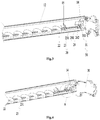
Fig. 1 is a structural schematic diagram of an embodiment of an air deflector assembly according to the present disclosure; -
Fig. 2 is a schematic diagram of a left side structure of an embodiment of an air deflector assembly according to the present disclosure; -
Fig. 3 is a schematic diagram of a right side structure of an embodiment of an air deflector assembly according to the present disclosure; -
Fig. 4 is a schematic diagram of a snap assembly structure of an embodiment of an air deflector assembly according to the present disclosure; -
Fig. 5 is an enlarged structural schematic diagram of A inFig. 4 . - Wherein, the above drawings include the following reference numerals:
- 10. air deflector portion;
- 11. first driving portion; 111. first output shaft; 112. rib;
- 12. air deflector; 13. first supporting block; 131. connecting hole; 132. cross-shaped groove; 14. second supporting block; 141. barb; 15. third supporting block;
- 20. air sweeping portion;
- 21. second driving portion; 211. second output shaft; 212. shaft hole; 213. first limiting flange;
- 22. air sweeping blades; 23. air sweeping connecting rod; 231. rod body portion;
- 24. snap assembly; 241. first snap element; 242. second snap element; 243. handle; 244. cantilever; 245. hook;
- 30. housing; 31. shaft sleeve; 311. second limiting flange.
- It should be noted that the embodiments and the features in the embodiments of the present disclosure can be combined with each other without conflict. Hereinafter, the present disclosure will be described in detail with reference to the accompanying drawings and embodiments.
- With reference to
Figs. 1 to 5 , an air deflector assembly is provided according to an embodiment of the present disclosure. - Specifically, as shown in
Fig. 1 , the air deflector assembly includes afirst driving portion 11, asecond driving portion 21, anair deflector portion 10 and anair sweeping portion 20, wherein the first drivingportion 11 is connected to theair deflector portion 10, theair deflector portion 10 driven by the first drivingportion 11 is rotatably arranged, and theair sweeping portion 20 is located at one side of theair deflector portion 10, thesecond driving portion 21 is connected to theair sweeping portion 20, and theair sweeping portion 20 driven by thesecond driving portion 21 is rotatably arranged, wherein theair sweeping portion 20 includes an air sweeping connectingrod 23, the air sweeping connectingrod 23 includes arod body portion 231 and asnap assembly 24, and therod body portion 231 is connected to theair deflector portion 10; thesnap assembly 24 is arranged at an end portion of therod body portion 231, and thesnap assembly 24 is snaped-fitted with thesecond driving portion 21. - In the present embodiment, the separation between the air sweeping portion and the air deflector portion is realized by arranging the snap assembly on the air sweeping connecting rod of the air sweeping portion and snap-fitting the snap assembly with the second driving portion, so that the service life of the portions is prolonged, the assembly reliability of the air deflector assembly is enhanced, the production efficiency is improved, and the cost of the whole machine is decreased.
- The
snap assembly 24 includes afirst snap element 241 and asecond snap element 242, thefirst snap element 241 and thesecond snap element 242 are arranged symmetrically along the circumferential direction of therod body portion 231, thesnap assembly 24 has an unlocking position and a locking position, and when thesnap assembly 24 is in the locking position, pressing thesnap assembly 24 can move a part of thefirst snap element 241 and a part of thesecond snap element 242 outward in a radial direction of therod body portion 231 to an unlocking position. - Wherein, the air deflector assembly further includes a support portion, the support portion is connected to the
air deflector portion 10, therod body portion 231 is connected to theair deflector portion 10 by the support portion, and one of theair deflector portion 10 and theair sweeping portion 20 is rotatably arranged relative to the other of theair deflector portion 10 and theair sweeping portion 20. In this way, theair deflector portion 10 and theair sweeping portion 20 work in cooperation with each other, and the reliability of the machine body is improved. - In the present embodiment, the first driving
portion 11 has afirst output shaft 111, thesecond driving portion 21 has asecond output shaft 211, and thefirst output shaft 111 and thesecond output shaft 211 are arranged coaxially. This arrangement facilitates improving the stability of the output shaft, and reduces vibration and reduces noise. - In addition, the first driving
portion 11 has afirst output shaft 111, theair deflector portion 10 includes anair deflector 12, the air deflector is connected to the first drivingportion 11, and theair deflector 12 extends along the axial direction of thefirst output shaft 111. This arrangement facilitates theair deflector 12 to achieve a better air deflector effect. - As shown in
Fig. 2 , theair deflector portion 10 includes anair deflector 12, the first drivingportion 11 has afirst output shaft 111, the support portion further includes a first supportingblock 13, the first supportingblock 13 is arranged on a side, close to the first drivingportion 11, of theair deflector 12, and a connectinghole 131 is arranged on the first supportingblock 13, thefirst output shaft 111 penetrates through the connectinghole 131, and an outer circumferential surface of thefirst output shaft 111 is connected cooperatively with a hole wall of the connectinghole 131. In this way, the driving shaft and the first supporting block are conveniently connected, so that the first drivingportion 11 better acts on theair deflector 12 so as to change the direction of theair deflector 12. - In an exemplary embodiment, the cross section of the connecting
hole 131 in the radial direction is across-shaped groove 132, and the outer circumferential surface of thefirst output shaft 111 is provided with arib 112 matching with the cross-shaped groove. This arrangement makes the drive shaft and the first supporting block more closely connected. - As shown in
Figs. 2 and5 , the air deflector assembly further includes a support portion, the support portion further includes a second supportingblock 14, the second supportingblock 14 is arranged on a side, close to thesecond driving portion 21, of theair deflector 12, and the second supportingblock 14 is arranged on a side, facing the air sweeping connectingrod 23, of theair deflector 12, the end of the second supportingblock 14 is provided with abarb 141 for connecting with the mounting base, and theair deflector 12 is rotatably arranged relative to the mounting base by thebarb 141. This arrangement enables the second supporting block not only to support the circumferential rotation of theair deflector 12, but also facilitates the disassembly of other components due to the arrangement of thebarbs 141. The mounting base here is an motor housing of the motor assembly of the second driving portion, the motor housing achieve an effect of a protection of a motor, and the motor housing can be integrally arranged with thehousing 30 or can be arranged separately from the motor. - As shown in
Figs. 4 and5 , the support portion further includes a first supportingblock 13 and a third supportingblock 15, the first supportingblock 13 is arranged on a side, close to the first drivingportion 11, of theair deflector 12, and the third supportingblock 15 is connected to theair deflector 12, the third supportingblock 15 is arranged between the first supportingblock 13 and the second supportingblock 14, the third supportingblock 15 is provided with a through hole, and the center of the through hole coincides with the axis of thesecond output shaft 211. This arrangement facilitates the third supportingblock 15 to support the air sweeping connectingrod 23 circumferentially. - As shown in
Figs. 3 and 4 , the air sweeping connectingrod 23 is connected to theair deflector portion 10 by a support portion, the air sweeping connectingrod 23 is arranged along the longitudinal direction of theair deflector portion 10, and one end of the air sweeping connectingrod 23 is connected to thesecond output shaft 211, the axis of the air sweeping connectingrod 23 is coaxially arranged with thefirst output shaft 111 and thesecond output shaft 211, so as to reduce vibration and noise of thefirst output shaft 111 and thesecond output shaft 211. - In an exemplary embodiment, the air sweeping portion further includes a plurality of air sweeping blades, the plurality of air
sweeping blades 22 are arranged on the air sweeping connectingrod 23 at intervals, and thesecond output shaft 211 drives the air sweeping connectingrod 23 to rotate to change the air sweeping direction of the plurality of airsweeping blades 22. In this way, theair sweeping portion 20 is conveniently arranged to change the wind direction. - As shown in
Fig. 5 , thesecond driving portion 21 has asecond output shaft 211, thefirst snap element 241 includes acantilever 244 and ahandle 243, the first end of thecantilever 244 is connected to therod body portion 231, and the second end of thecantilever 244 extends outward in the radial direction of therod body portion 231; the middle portion of thehandle 243 is connected to the second end of thecantilever 244, and the first end of thehandle 243 extends toward thesecond output shaft 211 and gradually bends toward the axial side of therod body portion 231 to form ahook 245, the second end of thehandle 243 is gradually extended away from thesecond output shaft 211 in the axial direction of therod body portion 231, and the second end of thehandle 243 is pressed to move the first end of thehandle 243 outward to the unlocking position in the radial direction of therod body portion 231, thehook 245 is snap-fitted to the outer surface of thesecond output shaft 211, or thehook 245 is snap-fitted to the mounting base. The mounting base here is that the motor housing of the motor assembly being provided on the second driving portion, the motor housing serves to protect the motor, and the motor housing may be integrally provided with thehousing 30, or may be individually connected with the motor. In this way, thesnap assembly 24 is conveniently snap-fitted with the outer surface of thesecond output shaft 211 or the mounting base, preferably, thesnap assembly 24 is snap-fitted to the outer surface of thesecond output shaft 211, so that thesnap assembly 24 and thesecond output shaft 211 are conveniently rotated at the same speed and avoiding noisy caused by relative movement. - In an exemplary embodiment, the structure of the
second snap element 242 is the same as that of thefirst snap element 241, and thesecond snap element 242 is configured to be snap-fitted to the outer surface of thesecond output shaft 211, or thesecond snap element 242 is configured to be snap-fitted to the mounting base. In this way, thesnap assembly 24 is arranged to keep symmetrical left and right, so that thesnap assembly 24 is better connected. - In the present embodiment, the
second output shaft 211 includes an output shaft body, the axial direction of the output shaft body is provided with ashaft hole 212 for connecting with therod body portion 231, the outer circumferential surface of the output shaft body is provided with a first limitingflange 213 cooperated with thehook 245, or the mounting base is provided with a second limitingflange 311 cooperated with thehook 245. In this way, thehook 245 of thesnap assembly 24 is snap-fitting to the first limitingflange 213, which implements a limit of thesecond output shaft 211 in the axial direction, and implements thesnap assembly 24 to rotate along the circumferential direction of the first limitingflange 213, or thehook 245 of thesnap assembly 24 is snap-fitted to the second limitingflange 311, which implements a limit of thesecond output shaft 211 in the axial direction, and implements thesnap assembly 24 to rotate along the circumferential direction of the second limitingflange 311. - The cross section of the
shaft hole 212 in the radial direction is of hexagonal shaped. In this way, thesecond output shaft 211 is conveniently connected to therod body portion 231 by theshaft hole 212. - As shown in
Figs. 1 to 5 , the air deflector assembly of the above embodiment can also be used in the technical field of air conditioner device, that is, according to another aspect of the present disclosure, an indoor unit is provided. The indoor unit includes an air deflector assembly, and the air deflector assembly is the air deflector assembly in the above mentioned embodiment. - In the present embodiment, the indoor unit includes a
housing 30, the air deflector assembly is arranged on thehousing 30, thehousing 30 is provided with ashaft sleeve 31, thesecond output shaft 211 is penetrated into theshaft sleeve 31, and thebarb 141 of the second supportingblock 14 of the air deflector assembly is sleeved on the outer surface of theshaft sleeve 31. In this way, it is easy to disassemble the air deflector portion. - In the present embodiment, when the
snap assembly 24 of the air deflector assembly is in the locking position, thesnap assembly 24 is snap-fitted with thesecond output shaft 211, or when thesnap assembly 24 of the air deflector assembly is in the locking position, thesnap assembly 24 is snap-fitted with theshaft sleeve 31. This arrangement facilitates easy disassembly of the air sweeping portion. - In addition, in the technical field of air conditioner device in the above mentioned embodiments, according to another aspect of the present disclosure, an air conditioner is further provided, wherein the air conditioner includes an air deflector assembly, and the air deflector assembly is the air deflector assembly in the above mentioned embodiments.
- In the prior art, the reliability of the assembly method of the air sweeping blade is low, and after many times disassembling the air sweeping blade, the motor shaft driving the air sweeping blade is easy to be break, and in order to solve this problem, a new assembly method of the air sweeping portion isprovided, that is, the air sweeping connecting rod is snap-fitted with the driving structure by the snap assembly, meanwhile, the air sweeping portion and the air deflector portion are rotated coaxially, thereby improving overall assembly production efficiency and overall product reliability.
- As shown in
Fig. 1 , in order to reduce the cost of the whole machine, improve the assembly production efficiency and improve the reliability of the whole machine, the present disclosure provides a new assembly manner of a air sweeping blades, and it can be seen from the drawing that the air sweeping blades are mounted on an air deflector by a first supportingblock 13 and a second supportingblock 14. Thefirst driving portion 11 is configured to drive the air deflector, and thesecond driving portion 21 is configured to drive the air sweeping blades. It can be seen from the drawing that thefirst output shaft 111 driving the air deflector and thesecond output shaft 211 driving the air sweeping blades are on the same axis, that is, are driven coaxially. - As shown in
Figs. 3 to 5 , asnap assembly 24 is arranged on the connection end of the air sweeping connectingrod 23, and its working principle is that: when assembling or disassembling the air sweeping portion, when thehandle 243 is pressed, and thecantilever 244 is deformed, and the opening of thehook 245 opens, and when the handle is released, the opening of thehook 245 returns to the original position, thereby assembling or disassembling the air sweeping blades. In addition, a six-pillar structure is designed on the end of the air sweeping connecting rod, and a six-pillar hole is designed on the second output shaft on the driving structure, and the six-pillar structure is inserted into the six-pillar hole to realize the hexagonal transmission mode. Through the improvement of the above structure, the problem of breakage of the drive shaft of the motor after many times disassembled is avoided, and the reliability of the whole machine is improved. - In addition, two solutions of snap-fitted are engaged with the air sweeping connecting rod:
In a first solution, the snap assembly of the air sweeping connectingrod 23 is snap-fitted to the mounting base, wherein the mounting base may be theshaft sleeve 31 of the motor on the motor assembly, and the second limitingflange 311 on theshaft sleeve 31 inFig. 5 is designed to facilitate the snap-fitting of the snap assembly without disengaging. Theshaft sleeve 31 is not moving, that is, there is relative movement between the snap assembly on the air sweeping connecting rod and the shaft sleeve. Such a structure can be conveniently disassembled, but there is a defect that there is relative movement between the snap assembly on the air sweeping connecting rod and theshaft sleeve 31 of the motor, which causes friction, thereby causing an anomalous noisy. - In a second solution, the snap assembly on the air sweeping connecting rod is snap-fitted to the first limiting
flange 213 of the second output shaft, and the rotation of the second output shaft drives the air sweeping connecting rod to rotate. The snap assembly on the air sweeping connecting rod rotates with the second output shaft, and they are relatively stationary, and this design can effectively avoid the occurrence of an anomalous noisy due to friction, thereby improving the user's feeling. - The above description is merely a preferred embodiment of the present disclosure, and is not intended to limit the present disclosure, and various changes and modifications may be made by those skilled in the art. Any modifications, equivalent replacements and improvements made within the spirit and principle of the present disclosure shall fall within the scope of protection of the present disclosure.
Claims (19)
- An air deflector assembly, comprising:a first driving portion (11);a second driving portion (21);an air deflector portion (10), wherein the first driving portion (11) is connected to the air deflector portion (10), and the air deflector portion (10) driven by the first driving portion (11) is rotatably arranged; andan air sweeping portion (20), wherein the air sweeping portion (20) is located on a side of the air deflector portion (10), the second driving portion (21) is connected to the air sweeping portion (20), and the air sweeping portion (20) driven by the second driving portion (21) is rotatably arranged;wherein the air sweeping portion (20) comprises an air sweeping connecting rod (23), and the air sweeping connecting rod (23) comprises:a rod body portion (231) connected to the air deflector portion (10); anda snap assembly (24) provided at an end portion of the rod body portion (231), the snap assembly (24) being snap-fitted with the second driving portion (21).
- The air deflector assembly as claimed in claim 1, wherein the snap assembly (24) comprises a first snap element (241) and a second snap element (242), the first snap element (241) and the second snap element (242) are arranged symmetrically along a circumferential direction of the rod body portion (231), the snap assembly (24) has an unlocking position and a locking position, and when the snap assembly (24) is in the locking position, pressing the snap assembly (24) can move a part of the first snap element (241) and a part of the second snap element (242) outward in a radial direction of the rod body portion (231) to the unlocking position.
- The air deflector assembly as claimed in claim 1, further comprising:
a support portion, wherein the support portion is connected to the air deflector portion (10), the rod body portion (231) is connected to the air deflector portion (10) by the support portion, and one of the air deflector portion (10) and the air sweeping portion (20) is rotatably arranged relative to the other of the air deflector portion (10) and the air sweeping portion (20). - The air deflector assembly as claimed in claim 1, wherein the first driving portion (11) has a first output shaft (111), the second driving portion (21) has a second output shaft (211), and the first output shaft (111) and the second output shaft (211) are arranged coaxially.
- The air deflector assembly as claimed in claim 1, wherein the first driving portion (11) has a first output shaft (111), and the air deflector portion (10) comprises:
an air deflector (12) connected to the first driving portion (11), and the air deflector (12) extends along an axial direction of the first output shaft (111). - The air deflector assembly as claimed in claim 3, wherein the air deflector portion (10) comprises an air deflector (12), the first driving portion (11) has a first output shaft (111), and the support portion further comprises:
a first supporting block (13), wherein the first supporting block (13) is arranged on a side, close to the first driving portion (11), of the air deflector (12), and the first supporting block (13) is provided with a connecting hole (131); the first output shaft (111) is penetrated into the connecting hole (131), and an outer circumferential surface of the first output shaft (111) is cooperatively connected to a hole wall of the connecting hole (131). - The air deflector assembly as claimed in claim 6, wherein a cross section of the connecting hole (131) in a radial direction is a cross-shaped groove (132), and the outer circumferential surface of the first output shaft (111) is provided with a rib (112) matching with the cross-shaped groove (132).
- The air deflector assembly as claimed in claim 5, wherein the air deflector assembly further comprises a support portion, and the support portion comprises:
a second supporting block (14), wherein the second supporting block (14) is arranged on a side, close to the second driving portion (21), of the air deflector (12), and the second supporting block (14) is arranged on a side, facing towards the air sweeping connecting rod (23), of the air deflector (12), an end of the second supporting block (14) is provided with a barb (141) for connecting with a mounting base, and the air deflector (12) is rotatably disposed relative to the mounting base by the barb (141). - The air deflector assembly as claimed in claim 8, wherein the support portion further comprises:a first supporting block (13), wherein the first supporting block (13) is provided on a side, close to the first driving portion (11), of the air deflector (12); anda third supporting block (15), wherein the third supporting block (15) is connected to the air deflector (12), the third supporting block (15) is arranged between the first supporting block (13) and the second supporting block (14), the third supporting block (15) is provided with a through hole, and a center of the through hole coincides with an axis of a second output shaft (211).
- The air deflector assembly as claimed in claim 4, wherein
the air sweeping connecting rod (23) is arranged along a longitudinal direction of the air deflector portion (10), one end of the air sweeping connecting rod (23) is connected to the second output shaft (211), and an axis of the air sweeping connecting rod (23) is arranged coaxially with the first output shaft (111) and the second output shaft (211). - The air deflector assembly as claimed in claim 4, wherein the air sweeping portion (20) further comprises:
a plurality of air sweeping blades; the plurality of air sweeping blades (22) are arranged on the air sweeping connecting rod (23) at intervals, the second output shaft (211) drives the air sweeping connecting rod (23) to rotate to change an air sweeping direction of the plurality of air sweeping blades (22). - The air deflector assembly as claimed in claim 2, wherein the second driving portion (21) has a second output shaft (211), and the first snap element (241) comprises:a cantilever (244), a first end of the cantilever (244) being connected to the rod body portion (231), and a second end of the cantilever (244) extending outward in a radial direction of the rod body portion (231);a handle (243), wherein a middle portion of the handle (243) is connected to the second end of the cantilever (244), a first end of the handle (243) extends toward the second output shaft (211) and gradually bends toward a side of an axis of the rod body portion (231) to form a hook (245), a second end of the handle (243) is gradually extended away from the second output shaft (211) along an axial direction of the rod body portion (231), pressing the second end of the handle (243) can move the first end of the handle (243) outward in a radial direction of the rod body portion (231) to the unlocking position, and the hook (245) is snap-fitting to an outer surface of the second output shaft (211), or the hook (245) is used for snap-fitted to a mounting base.
- The air deflector assembly as claimed in claim 12, wherein a structure of the second snap element (242) is the same as a structure of the first snap element (241), and the second snap element (242) is configured to be snap-fitted to an outer surface of the second output shaft (211), or the second snap element (242) is configured to be snap-fitted to the mounting base.
- The air deflector assembly as claimed in claim 12, wherein
the second output shaft (211) comprises an output shaft body, an axial direction of the output shaft body is provided with a shaft hole (212) for connecting with the rod body portion (231), an outer circumferential surface of the output shaft body is provided with a first limiting flange (213) cooperated with the hook (245), or
the mounting base is provided with a second limiting flange (311) cooperated with the hook (245). - The air deflector assembly as claimed in claim 14, wherein a cross section of the shaft hole (212) in a radial direction is of hexagonal shaped.
- An indoor unit, comprising an air deflector assembly, wherein the air deflector assembly is the air deflector assembly as claimed in any one of claims 1 to 15.
- The indoor unit as claimed in claim 16, wherein the indoor unit comprises:
a housing (30), wherein the air deflector assembly is arranged on the housing (30), the housing (30) is provided with a shaft sleeve (31), a second output shaft (211) is penetrated into the shaft sleeve (31), and a barb (141) of a second supporting block (14) of the air deflector assembly is sleeved on an outer surface of the shaft sleeve (31). - The indoor unit as claimed in claim 17, wherein when a snap assembly (24) of the air deflector assembly is in a locking position, the snap assembly (24) is snap-fitted with the second output shaft (211), or when the snap assembly (24) of the air deflector assembly is in a locking position, the snap assembly (24) is snap-fitted with the shaft sleeve (31).
- An air conditioner, comprising an air deflector assembly, wherein the air deflector assembly is the air deflector assembly as claimed in any one of claims 1 to 15.
Applications Claiming Priority (2)
| Application Number | Priority Date | Filing Date | Title |
|---|---|---|---|
| CN201810214489.0A CN108361948B (en) | 2018-03-15 | 2018-03-15 | Air guide assembly and air conditioner with same |
| PCT/CN2018/103557 WO2019174199A1 (en) | 2018-03-15 | 2018-08-31 | Air guide assembly and air conditioner provided with same |
Publications (3)
| Publication Number | Publication Date |
|---|---|
| EP3767195A1 true EP3767195A1 (en) | 2021-01-20 |
| EP3767195A4 EP3767195A4 (en) | 2021-12-08 |
| EP3767195B1 EP3767195B1 (en) | 2023-11-08 |
Family
ID=63000293
Family Applications (1)
| Application Number | Title | Priority Date | Filing Date |
|---|---|---|---|
| EP18901809.6A Active EP3767195B1 (en) | 2018-03-15 | 2018-08-31 | Air guide assembly and air conditioner provided with same |
Country Status (4)
| Country | Link |
|---|---|
| EP (1) | EP3767195B1 (en) |
| CN (1) | CN108361948B (en) |
| AU (1) | AU2018405436B2 (en) |
| WO (1) | WO2019174199A1 (en) |
Families Citing this family (8)
| Publication number | Priority date | Publication date | Assignee | Title |
|---|---|---|---|---|
| CN108679727B (en) * | 2018-08-24 | 2023-10-13 | 珠海格力电器股份有限公司 | Air sweeping mechanism and air conditioner with same |
| CN108954771A (en) * | 2018-09-18 | 2018-12-07 | 珠海格力电器股份有限公司 | Sweep wind blade subassembly and air conditioner |
| CN110274378A (en) * | 2019-07-18 | 2019-09-24 | 格力电器(武汉)有限公司 | Detachable sweeps wind blade device and air-out equipment |
| CN110578963B (en) * | 2019-09-29 | 2023-09-29 | 海信空调有限公司 | Air conditioner |
| CN214148145U (en) * | 2021-01-18 | 2021-09-07 | 北京小米移动软件有限公司 | Swing blade rotating structure of cylindrical cabinet machine |
| CN113566292B (en) * | 2021-08-17 | 2025-05-02 | 珠海格力电器股份有限公司 | Air conditioner and control method thereof |
| CN113719999B (en) * | 2021-09-03 | 2024-12-31 | 珠海格力电器股份有限公司 | Air guide structure and air conditioner having the same |
| CN115628531B (en) * | 2022-11-08 | 2024-09-03 | 珠海格力电器股份有限公司 | Air conditioning assembly, air conditioner and control method |
Family Cites Families (6)
| Publication number | Priority date | Publication date | Assignee | Title |
|---|---|---|---|---|
| JP2996146B2 (en) * | 1995-08-11 | 1999-12-27 | ダイキン工業株式会社 | Wind direction adjustment blade support structure for air conditioner |
| JP2002031404A (en) * | 2000-07-19 | 2002-01-31 | Sanyo Electric Co Ltd | Air conditioner |
| EP2327938A4 (en) * | 2008-08-22 | 2015-07-01 | Toshiba Carrier Corp | INDOOR AIR CONDITIONER MACHINE |
| JP2010078273A (en) * | 2008-09-29 | 2010-04-08 | Daikin Ind Ltd | Air conditioner |
| CN202928039U (en) * | 2012-11-06 | 2013-05-08 | 广东美的电器股份有限公司 | Air conditioner with large air supply range |
| CN103528175B (en) * | 2013-10-09 | 2017-09-15 | Tcl空调器(中山)有限公司 | Air conditioner and its air ducting |
-
2018
- 2018-03-15 CN CN201810214489.0A patent/CN108361948B/en active Active
- 2018-08-31 AU AU2018405436A patent/AU2018405436B2/en active Active
- 2018-08-31 EP EP18901809.6A patent/EP3767195B1/en active Active
- 2018-08-31 WO PCT/CN2018/103557 patent/WO2019174199A1/en not_active Ceased
Also Published As
| Publication number | Publication date |
|---|---|
| WO2019174199A1 (en) | 2019-09-19 |
| EP3767195B1 (en) | 2023-11-08 |
| CN108361948A (en) | 2018-08-03 |
| AU2018405436B2 (en) | 2020-08-27 |
| AU2018405436A1 (en) | 2019-10-03 |
| CN108361948B (en) | 2019-08-06 |
| EP3767195A4 (en) | 2021-12-08 |
Similar Documents
| Publication | Publication Date | Title |
|---|---|---|
| EP3767195A1 (en) | Air guide assembly and air conditioner provided with same | |
| US6463623B2 (en) | Power brush assembly for vacuum cleaners | |
| KR101933724B1 (en) | A system for the construction of an axial fan | |
| CN201954722U (en) | Air guide connecting rod mechanism and air conditioner with same | |
| US12044244B2 (en) | Ceiling fan blade and grommet | |
| WO2019174336A1 (en) | Fan blade support assembly for fan blade, air duct assembly, and air conditioner | |
| JP2012065524A (en) | Rotary shaft support mechanism and magnet motor having the same | |
| CN208012036U (en) | Air guide assembly and air conditioner with same | |
| CN216589251U (en) | Bearing assembly, air supply device and air conditioner | |
| CN216000303U (en) | Efficient electric nut gun head with long service life | |
| JP2002295887A (en) | Air conditioner | |
| CN212274096U (en) | Wind wheel, wind wheel assembly structure and air conditioner | |
| CN215058289U (en) | Fan system and household appliances | |
| CN104633890A (en) | Stabilizing device of motor rotating shaft, panel assembly and air conditioner | |
| EP4030108A1 (en) | Rotary blade structure for cylindrical cabinet indoor unit and cylindrical cabinet indoor unit | |
| KR101110970B1 (en) | Built-in swing mechanism of rotary fan | |
| CN106016659A (en) | Air guide mechanism and air conditioner with same | |
| CN224214588U (en) | A bearing support structure | |
| CN108297013B (en) | Press mounting tool for riveting fixing sleeve | |
| CN222315731U (en) | Automobile air conditioning clutch hub | |
| CN222953825U (en) | Permanent magnet motor | |
| CN220857722U (en) | Motor assembly and electric tool | |
| CN217842112U (en) | Fan blade structure, fan and air conditioner | |
| CN222617030U (en) | Air outlet structure and air conditioner | |
| CN217720957U (en) | Permanent magnet motor |
Legal Events
| Date | Code | Title | Description |
|---|---|---|---|
| STAA | Information on the status of an ep patent application or granted ep patent |
Free format text: STATUS: UNKNOWN |
|
| STAA | Information on the status of an ep patent application or granted ep patent |
Free format text: STATUS: THE INTERNATIONAL PUBLICATION HAS BEEN MADE |
|
| PUAI | Public reference made under article 153(3) epc to a published international application that has entered the european phase |
Free format text: ORIGINAL CODE: 0009012 |
|
| STAA | Information on the status of an ep patent application or granted ep patent |
Free format text: STATUS: REQUEST FOR EXAMINATION WAS MADE |
|
| 17P | Request for examination filed |
Effective date: 20190731 |
|
| AK | Designated contracting states |
Kind code of ref document: A1 Designated state(s): AL AT BE BG CH CY CZ DE DK EE ES FI FR GB GR HR HU IE IS IT LI LT LU LV MC MK MT NL NO PL PT RO RS SE SI SK SM TR |
|
| AX | Request for extension of the european patent |
Extension state: BA ME |
|
| DAV | Request for validation of the european patent (deleted) | ||
| DAX | Request for extension of the european patent (deleted) | ||
| A4 | Supplementary search report drawn up and despatched |
Effective date: 20211108 |
|
| RIC1 | Information provided on ipc code assigned before grant |
Ipc: F24F 1/0011 20190101ALI20211102BHEP Ipc: F24F 13/14 20060101ALI20211102BHEP Ipc: F24F 13/15 20060101AFI20211102BHEP |
|
| GRAP | Despatch of communication of intention to grant a patent |
Free format text: ORIGINAL CODE: EPIDOSNIGR1 |
|
| STAA | Information on the status of an ep patent application or granted ep patent |
Free format text: STATUS: GRANT OF PATENT IS INTENDED |
|
| INTG | Intention to grant announced |
Effective date: 20230614 |
|
| P01 | Opt-out of the competence of the unified patent court (upc) registered |
Effective date: 20230530 |
|
| GRAS | Grant fee paid |
Free format text: ORIGINAL CODE: EPIDOSNIGR3 |
|
| GRAA | (expected) grant |
Free format text: ORIGINAL CODE: 0009210 |
|
| STAA | Information on the status of an ep patent application or granted ep patent |
Free format text: STATUS: THE PATENT HAS BEEN GRANTED |
|
| AK | Designated contracting states |
Kind code of ref document: B1 Designated state(s): AL AT BE BG CH CY CZ DE DK EE ES FI FR GB GR HR HU IE IS IT LI LT LU LV MC MK MT NL NO PL PT RO RS SE SI SK SM TR |
|
| REG | Reference to a national code |
Ref country code: GB Ref legal event code: FG4D |
|
| REG | Reference to a national code |
Ref country code: CH Ref legal event code: EP |
|
| REG | Reference to a national code |
Ref country code: DE Ref legal event code: R096 Ref document number: 602018060994 Country of ref document: DE |
|
| REG | Reference to a national code |
Ref country code: IE Ref legal event code: FG4D |
|
| REG | Reference to a national code |
Ref country code: LT Ref legal event code: MG9D |
|
| REG | Reference to a national code |
Ref country code: NL Ref legal event code: MP Effective date: 20231108 |
|
| PG25 | Lapsed in a contracting state [announced via postgrant information from national office to epo] |
Ref country code: GR Free format text: LAPSE BECAUSE OF FAILURE TO SUBMIT A TRANSLATION OF THE DESCRIPTION OR TO PAY THE FEE WITHIN THE PRESCRIBED TIME-LIMIT Effective date: 20240209 |
|
| PG25 | Lapsed in a contracting state [announced via postgrant information from national office to epo] |
Ref country code: IS Free format text: LAPSE BECAUSE OF FAILURE TO SUBMIT A TRANSLATION OF THE DESCRIPTION OR TO PAY THE FEE WITHIN THE PRESCRIBED TIME-LIMIT Effective date: 20240308 |
|
| PG25 | Lapsed in a contracting state [announced via postgrant information from national office to epo] |
Ref country code: LT Free format text: LAPSE BECAUSE OF FAILURE TO SUBMIT A TRANSLATION OF THE DESCRIPTION OR TO PAY THE FEE WITHIN THE PRESCRIBED TIME-LIMIT Effective date: 20231108 |
|
| REG | Reference to a national code |
Ref country code: AT Ref legal event code: MK05 Ref document number: 1629918 Country of ref document: AT Kind code of ref document: T Effective date: 20231108 |
|
| PG25 | Lapsed in a contracting state [announced via postgrant information from national office to epo] |
Ref country code: NL Free format text: LAPSE BECAUSE OF FAILURE TO SUBMIT A TRANSLATION OF THE DESCRIPTION OR TO PAY THE FEE WITHIN THE PRESCRIBED TIME-LIMIT Effective date: 20231108 |
|
| PG25 | Lapsed in a contracting state [announced via postgrant information from national office to epo] |
Ref country code: AT Free format text: LAPSE BECAUSE OF FAILURE TO SUBMIT A TRANSLATION OF THE DESCRIPTION OR TO PAY THE FEE WITHIN THE PRESCRIBED TIME-LIMIT Effective date: 20231108 |
|
| PG25 | Lapsed in a contracting state [announced via postgrant information from national office to epo] |
Ref country code: ES Free format text: LAPSE BECAUSE OF FAILURE TO SUBMIT A TRANSLATION OF THE DESCRIPTION OR TO PAY THE FEE WITHIN THE PRESCRIBED TIME-LIMIT Effective date: 20231108 |
|
| PG25 | Lapsed in a contracting state [announced via postgrant information from national office to epo] |
Ref country code: NL Free format text: LAPSE BECAUSE OF FAILURE TO SUBMIT A TRANSLATION OF THE DESCRIPTION OR TO PAY THE FEE WITHIN THE PRESCRIBED TIME-LIMIT Effective date: 20231108 Ref country code: LT Free format text: LAPSE BECAUSE OF FAILURE TO SUBMIT A TRANSLATION OF THE DESCRIPTION OR TO PAY THE FEE WITHIN THE PRESCRIBED TIME-LIMIT Effective date: 20231108 Ref country code: IS Free format text: LAPSE BECAUSE OF FAILURE TO SUBMIT A TRANSLATION OF THE DESCRIPTION OR TO PAY THE FEE WITHIN THE PRESCRIBED TIME-LIMIT Effective date: 20240308 Ref country code: GR Free format text: LAPSE BECAUSE OF FAILURE TO SUBMIT A TRANSLATION OF THE DESCRIPTION OR TO PAY THE FEE WITHIN THE PRESCRIBED TIME-LIMIT Effective date: 20240209 Ref country code: ES Free format text: LAPSE BECAUSE OF FAILURE TO SUBMIT A TRANSLATION OF THE DESCRIPTION OR TO PAY THE FEE WITHIN THE PRESCRIBED TIME-LIMIT Effective date: 20231108 Ref country code: BG Free format text: LAPSE BECAUSE OF FAILURE TO SUBMIT A TRANSLATION OF THE DESCRIPTION OR TO PAY THE FEE WITHIN THE PRESCRIBED TIME-LIMIT Effective date: 20240208 Ref country code: AT Free format text: LAPSE BECAUSE OF FAILURE TO SUBMIT A TRANSLATION OF THE DESCRIPTION OR TO PAY THE FEE WITHIN THE PRESCRIBED TIME-LIMIT Effective date: 20231108 Ref country code: PT Free format text: LAPSE BECAUSE OF FAILURE TO SUBMIT A TRANSLATION OF THE DESCRIPTION OR TO PAY THE FEE WITHIN THE PRESCRIBED TIME-LIMIT Effective date: 20240308 |
|
| PG25 | Lapsed in a contracting state [announced via postgrant information from national office to epo] |
Ref country code: SE Free format text: LAPSE BECAUSE OF FAILURE TO SUBMIT A TRANSLATION OF THE DESCRIPTION OR TO PAY THE FEE WITHIN THE PRESCRIBED TIME-LIMIT Effective date: 20231108 Ref country code: RS Free format text: LAPSE BECAUSE OF FAILURE TO SUBMIT A TRANSLATION OF THE DESCRIPTION OR TO PAY THE FEE WITHIN THE PRESCRIBED TIME-LIMIT Effective date: 20231108 Ref country code: PL Free format text: LAPSE BECAUSE OF FAILURE TO SUBMIT A TRANSLATION OF THE DESCRIPTION OR TO PAY THE FEE WITHIN THE PRESCRIBED TIME-LIMIT Effective date: 20231108 Ref country code: NO Free format text: LAPSE BECAUSE OF FAILURE TO SUBMIT A TRANSLATION OF THE DESCRIPTION OR TO PAY THE FEE WITHIN THE PRESCRIBED TIME-LIMIT Effective date: 20240208 Ref country code: LV Free format text: LAPSE BECAUSE OF FAILURE TO SUBMIT A TRANSLATION OF THE DESCRIPTION OR TO PAY THE FEE WITHIN THE PRESCRIBED TIME-LIMIT Effective date: 20231108 Ref country code: HR Free format text: LAPSE BECAUSE OF FAILURE TO SUBMIT A TRANSLATION OF THE DESCRIPTION OR TO PAY THE FEE WITHIN THE PRESCRIBED TIME-LIMIT Effective date: 20231108 |
|
| PG25 | Lapsed in a contracting state [announced via postgrant information from national office to epo] |
Ref country code: DK Free format text: LAPSE BECAUSE OF FAILURE TO SUBMIT A TRANSLATION OF THE DESCRIPTION OR TO PAY THE FEE WITHIN THE PRESCRIBED TIME-LIMIT Effective date: 20231108 |
|
| PG25 | Lapsed in a contracting state [announced via postgrant information from national office to epo] |
Ref country code: CZ Free format text: LAPSE BECAUSE OF FAILURE TO SUBMIT A TRANSLATION OF THE DESCRIPTION OR TO PAY THE FEE WITHIN THE PRESCRIBED TIME-LIMIT Effective date: 20231108 |
|
| PG25 | Lapsed in a contracting state [announced via postgrant information from national office to epo] |
Ref country code: SK Free format text: LAPSE BECAUSE OF FAILURE TO SUBMIT A TRANSLATION OF THE DESCRIPTION OR TO PAY THE FEE WITHIN THE PRESCRIBED TIME-LIMIT Effective date: 20231108 |
|
| PG25 | Lapsed in a contracting state [announced via postgrant information from national office to epo] |
Ref country code: SM Free format text: LAPSE BECAUSE OF FAILURE TO SUBMIT A TRANSLATION OF THE DESCRIPTION OR TO PAY THE FEE WITHIN THE PRESCRIBED TIME-LIMIT Effective date: 20231108 Ref country code: SK Free format text: LAPSE BECAUSE OF FAILURE TO SUBMIT A TRANSLATION OF THE DESCRIPTION OR TO PAY THE FEE WITHIN THE PRESCRIBED TIME-LIMIT Effective date: 20231108 Ref country code: RO Free format text: LAPSE BECAUSE OF FAILURE TO SUBMIT A TRANSLATION OF THE DESCRIPTION OR TO PAY THE FEE WITHIN THE PRESCRIBED TIME-LIMIT Effective date: 20231108 Ref country code: IT Free format text: LAPSE BECAUSE OF FAILURE TO SUBMIT A TRANSLATION OF THE DESCRIPTION OR TO PAY THE FEE WITHIN THE PRESCRIBED TIME-LIMIT Effective date: 20231108 Ref country code: EE Free format text: LAPSE BECAUSE OF FAILURE TO SUBMIT A TRANSLATION OF THE DESCRIPTION OR TO PAY THE FEE WITHIN THE PRESCRIBED TIME-LIMIT Effective date: 20231108 Ref country code: DK Free format text: LAPSE BECAUSE OF FAILURE TO SUBMIT A TRANSLATION OF THE DESCRIPTION OR TO PAY THE FEE WITHIN THE PRESCRIBED TIME-LIMIT Effective date: 20231108 Ref country code: CZ Free format text: LAPSE BECAUSE OF FAILURE TO SUBMIT A TRANSLATION OF THE DESCRIPTION OR TO PAY THE FEE WITHIN THE PRESCRIBED TIME-LIMIT Effective date: 20231108 |
|
| REG | Reference to a national code |
Ref country code: DE Ref legal event code: R097 Ref document number: 602018060994 Country of ref document: DE |
|
| PLBE | No opposition filed within time limit |
Free format text: ORIGINAL CODE: 0009261 |
|
| STAA | Information on the status of an ep patent application or granted ep patent |
Free format text: STATUS: NO OPPOSITION FILED WITHIN TIME LIMIT |
|
| 26N | No opposition filed |
Effective date: 20240809 |
|
| PG25 | Lapsed in a contracting state [announced via postgrant information from national office to epo] |
Ref country code: SI Free format text: LAPSE BECAUSE OF FAILURE TO SUBMIT A TRANSLATION OF THE DESCRIPTION OR TO PAY THE FEE WITHIN THE PRESCRIBED TIME-LIMIT Effective date: 20231108 |
|
| PG25 | Lapsed in a contracting state [announced via postgrant information from national office to epo] |
Ref country code: SI Free format text: LAPSE BECAUSE OF FAILURE TO SUBMIT A TRANSLATION OF THE DESCRIPTION OR TO PAY THE FEE WITHIN THE PRESCRIBED TIME-LIMIT Effective date: 20231108 |
|
| REG | Reference to a national code |
Ref country code: CH Ref legal event code: PL |
|
| PG25 | Lapsed in a contracting state [announced via postgrant information from national office to epo] |
Ref country code: LU Free format text: LAPSE BECAUSE OF NON-PAYMENT OF DUE FEES Effective date: 20240831 |
|
| GBPC | Gb: european patent ceased through non-payment of renewal fee |
Effective date: 20240831 |
|
| PG25 | Lapsed in a contracting state [announced via postgrant information from national office to epo] |
Ref country code: MC Free format text: LAPSE BECAUSE OF FAILURE TO SUBMIT A TRANSLATION OF THE DESCRIPTION OR TO PAY THE FEE WITHIN THE PRESCRIBED TIME-LIMIT Effective date: 20231108 Ref country code: CH Free format text: LAPSE BECAUSE OF NON-PAYMENT OF DUE FEES Effective date: 20240831 |
|
| REG | Reference to a national code |
Ref country code: BE Ref legal event code: MM Effective date: 20240831 |
|
| PG25 | Lapsed in a contracting state [announced via postgrant information from national office to epo] |
Ref country code: GB Free format text: LAPSE BECAUSE OF NON-PAYMENT OF DUE FEES Effective date: 20240831 |
|
| PG25 | Lapsed in a contracting state [announced via postgrant information from national office to epo] |
Ref country code: BE Free format text: LAPSE BECAUSE OF NON-PAYMENT OF DUE FEES Effective date: 20240831 |
|
| PG25 | Lapsed in a contracting state [announced via postgrant information from national office to epo] |
Ref country code: FR Free format text: LAPSE BECAUSE OF NON-PAYMENT OF DUE FEES Effective date: 20240831 |
|
| PG25 | Lapsed in a contracting state [announced via postgrant information from national office to epo] |
Ref country code: IE Free format text: LAPSE BECAUSE OF NON-PAYMENT OF DUE FEES Effective date: 20240831 |
|
| PG25 | Lapsed in a contracting state [announced via postgrant information from national office to epo] |
Ref country code: FI Free format text: LAPSE BECAUSE OF FAILURE TO SUBMIT A TRANSLATION OF THE DESCRIPTION OR TO PAY THE FEE WITHIN THE PRESCRIBED TIME-LIMIT Effective date: 20231108 |
|
| PGFP | Annual fee paid to national office [announced via postgrant information from national office to epo] |
Ref country code: DE Payment date: 20250819 Year of fee payment: 8 |
|
| PG25 | Lapsed in a contracting state [announced via postgrant information from national office to epo] |
Ref country code: CY Free format text: LAPSE BECAUSE OF FAILURE TO SUBMIT A TRANSLATION OF THE DESCRIPTION OR TO PAY THE FEE WITHIN THE PRESCRIBED TIME-LIMIT; INVALID AB INITIO Effective date: 20180831 |
|
| PG25 | Lapsed in a contracting state [announced via postgrant information from national office to epo] |
Ref country code: HU Free format text: LAPSE BECAUSE OF FAILURE TO SUBMIT A TRANSLATION OF THE DESCRIPTION OR TO PAY THE FEE WITHIN THE PRESCRIBED TIME-LIMIT; INVALID AB INITIO Effective date: 20180831 |