EP3767043A1 - Revolving work vehicle, and method for detecting position of working end of revolving work vehicle - Google Patents
Revolving work vehicle, and method for detecting position of working end of revolving work vehicle Download PDFInfo
- Publication number
- EP3767043A1 EP3767043A1 EP19767524.2A EP19767524A EP3767043A1 EP 3767043 A1 EP3767043 A1 EP 3767043A1 EP 19767524 A EP19767524 A EP 19767524A EP 3767043 A1 EP3767043 A1 EP 3767043A1
- Authority
- EP
- European Patent Office
- Prior art keywords
- revolving
- work machine
- work vehicle
- boom
- working end
- Prior art date
- Legal status (The legal status is an assumption and is not a legal conclusion. Google has not performed a legal analysis and makes no representation as to the accuracy of the status listed.)
- Pending
Links
- 238000000034 method Methods 0.000 title claims description 11
- 238000001514 detection method Methods 0.000 claims abstract description 9
- 230000006870 function Effects 0.000 description 10
- 230000008602 contraction Effects 0.000 description 6
- 230000001133 acceleration Effects 0.000 description 4
- 238000009412 basement excavation Methods 0.000 description 3
- 238000010276 construction Methods 0.000 description 2
- 238000010586 diagram Methods 0.000 description 1
- 238000005516 engineering process Methods 0.000 description 1
- 238000009434 installation Methods 0.000 description 1
- 238000005259 measurement Methods 0.000 description 1
- 238000012986 modification Methods 0.000 description 1
- 230000004048 modification Effects 0.000 description 1
Images




Classifications
-
- E—FIXED CONSTRUCTIONS
- E02—HYDRAULIC ENGINEERING; FOUNDATIONS; SOIL SHIFTING
- E02F—DREDGING; SOIL-SHIFTING
- E02F9/00—Component parts of dredgers or soil-shifting machines, not restricted to one of the kinds covered by groups E02F3/00 - E02F7/00
- E02F9/26—Indicating devices
- E02F9/264—Sensors and their calibration for indicating the position of the work tool
-
- B—PERFORMING OPERATIONS; TRANSPORTING
- B62—LAND VEHICLES FOR TRAVELLING OTHERWISE THAN ON RAILS
- B62D—MOTOR VEHICLES; TRAILERS
- B62D33/00—Superstructures for load-carrying vehicles
- B62D33/08—Superstructures for load-carrying vehicles comprising adjustable means
-
- E—FIXED CONSTRUCTIONS
- E02—HYDRAULIC ENGINEERING; FOUNDATIONS; SOIL SHIFTING
- E02F—DREDGING; SOIL-SHIFTING
- E02F3/00—Dredgers; Soil-shifting machines
- E02F3/04—Dredgers; Soil-shifting machines mechanically-driven
- E02F3/28—Dredgers; Soil-shifting machines mechanically-driven with digging tools mounted on a dipper- or bucket-arm, i.e. there is either one arm or a pair of arms, e.g. dippers, buckets
- E02F3/30—Dredgers; Soil-shifting machines mechanically-driven with digging tools mounted on a dipper- or bucket-arm, i.e. there is either one arm or a pair of arms, e.g. dippers, buckets with a dipper-arm pivoted on a cantilever beam, i.e. boom
- E02F3/32—Dredgers; Soil-shifting machines mechanically-driven with digging tools mounted on a dipper- or bucket-arm, i.e. there is either one arm or a pair of arms, e.g. dippers, buckets with a dipper-arm pivoted on a cantilever beam, i.e. boom working downwardly and towards the machine, e.g. with backhoes
-
- E—FIXED CONSTRUCTIONS
- E02—HYDRAULIC ENGINEERING; FOUNDATIONS; SOIL SHIFTING
- E02F—DREDGING; SOIL-SHIFTING
- E02F3/00—Dredgers; Soil-shifting machines
- E02F3/04—Dredgers; Soil-shifting machines mechanically-driven
- E02F3/28—Dredgers; Soil-shifting machines mechanically-driven with digging tools mounted on a dipper- or bucket-arm, i.e. there is either one arm or a pair of arms, e.g. dippers, buckets
- E02F3/36—Component parts
- E02F3/42—Drives for dippers, buckets, dipper-arms or bucket-arms
- E02F3/43—Control of dipper or bucket position; Control of sequence of drive operations
- E02F3/431—Control of dipper or bucket position; Control of sequence of drive operations for bucket-arms, front-end loaders, dumpers or the like
-
- E—FIXED CONSTRUCTIONS
- E02—HYDRAULIC ENGINEERING; FOUNDATIONS; SOIL SHIFTING
- E02F—DREDGING; SOIL-SHIFTING
- E02F9/00—Component parts of dredgers or soil-shifting machines, not restricted to one of the kinds covered by groups E02F3/00 - E02F7/00
- E02F9/08—Superstructures; Supports for superstructures
-
- E—FIXED CONSTRUCTIONS
- E02—HYDRAULIC ENGINEERING; FOUNDATIONS; SOIL SHIFTING
- E02F—DREDGING; SOIL-SHIFTING
- E02F9/00—Component parts of dredgers or soil-shifting machines, not restricted to one of the kinds covered by groups E02F3/00 - E02F7/00
- E02F9/08—Superstructures; Supports for superstructures
- E02F9/10—Supports for movable superstructures mounted on travelling or walking gears or on other superstructures
- E02F9/12—Slewing or traversing gears
- E02F9/121—Turntables, i.e. structure rotatable about 360°
- E02F9/123—Drives or control devices specially adapted therefor
Definitions
- the present invention relates to a revolving work vehicle having a so-called boom swing function and to a method for detecting a position of a working end of a work machine provided in the revolving work vehicle.
- a revolving work vehicle such as a backhoe
- high-precision control is allowed by detecting a position of a working end (for example, a blade edge of a bucket) of a work machine, and the high-precision control is useful for automation of work and ensuring safety of a surrounding area.
- a hydraulic shovel as the revolving work vehicle that includes means for detecting the position of the working end of the work machine is disclosed.
- a mini-shovel has a so-called boom swing function that not only allows the work machine to rotate vertically but also allows a base end of the work machine to rotate horizontally (that is, a boom swings to the right and left).
- a specific method for detecting the position of the working end with a high degree of accuracy has not been known for the revolving work vehicle with such a boom swing function.
- Patent Literature 1 a technique of detecting the position of the working end on the basis of output from a plurality of position sensors installed on the work machine and position information from two GPS antennas installed on a construction machine body is disclosed.
- this technology is adopted for the revolving work vehicle with the boom swing function, the position of the working end cannot be detected due to a change in a relative relationship between the output from the position sensors and the position information from the antennas caused by swing operation of the boom.
- Patent Literature 2 a technique of detecting a revolving center position of an arm on the basis of position information from a GPS antenna installed at a working end of the arm and position information from a GPS antenna installed on a construction machine body and further detecting a position of the working end on the basis of output from a plurality of position sensors has been disclosed.
- a technique of detecting a revolving center position of an arm on the basis of position information from a GPS antenna installed at a working end of the arm and position information from a GPS antenna installed on a construction machine body and further detecting a position of the working end on the basis of output from a plurality of position sensors has been disclosed.
- it is necessary to install the antenna at the working end, to which a significant vibration and a significant impact are applied this is inconvenient to detect the position of the working end with the high degree of accuracy.
- the present invention has been made in view of the above circumstances and therefore has an object to detect, with a high degree of accuracy, a position of a working end of a work machine in a revolving work vehicle having a boom swing function.
- a revolving work vehicle includes: a base carrier; a revolving superstructure provided above the base carrier in a manner capable of revolving; a swing body supported by the revolving superstructure in a horizontally rotatable manner; a work machine supported by the swing body in a vertically rotatable manner; a first position detecting device that detects a horizontal position of the swing body with respect to the revolving superstructure; a second position detecting device that detects a vertical position of the work machine with respect to the revolving superstructure; and an arithmetic unit that calculates a position of a working end of the work machine based on results of detection by the first and second position detecting devices.
- the first position detecting device may include a position sensor that is installed on the swing body.
- the work machine may include: a boom that is attached in a vertically rotatable manner to the swing body; an arm that is attached in a vertically rotatable manner to the boom; and a work attachment that is attached in a vertically rotatable manner to the arm, and the working end may be included in the work attachment.
- the second position measuring device may include: a position sensor that is installed on the boom; a position sensor that is installed on the arm; and a position sensor that is installed on a link for transmitting drive power to the work attachment.
- a method for detecting a position of a working end of a revolving work vehicle is used for the revolving work vehicle including: a revolving superstructure provided above a base carrier in a manner capable of revolving; a swing body supported by the revolving superstructure in a horizontally rotatable manner; and a work machine supported by the swing body in a vertically rotatable manner, and includes: detecting a horizontal position of the swing body with respect to the revolving superstructure by a first position detecting device; detecting a vertical position of the work machine with respect to the revolving superstructure by a second position detecting device; and calculating the position of the working end of the work machine based on results of detection by the first and second position detecting devices.
- a revolving work vehicle 1 includes: a base carrier 2, a revolving superstructure 3 provided above the base carrier 2 in a manner capable of revolving; a boom bracket 4 that is a swing body supported by the revolving superstructure 3 in a manner capable of rotating horizontally; and a work machine 5 that is supported by the boom bracket 4 in a manner capable of rotating vertically.
- the revolving work vehicle 1 is configured as a shovel (a backhoe) with a boom swing function.
- the boom swing function is provided in a mini-shovel, for which workability in a small area is requested.
- the base carrier 2 is driven when receiving power from an engine 30, and thereby drives or rotates the revolving work vehicle 1.
- the base carrier 2 includes: a pair of right and left crawlers 21, 21; and a pair of right and left travel motors 22, 22 for driving those. Between the paired crawlers 21, 21, a base 23 is provided to support the revolving superstructure 3 in a manner to allow free revolution thereof.
- the base carrier 2 is also provided with: a pair of blade arms 24, 24; a blade 25 as an earth removing plate that extends in a right-left direction between tips of the blade arms 24, 24; and a blade cylinder 26 for vertically rotating the blade 25.
- the revolving superstructure 3 is configured to be able to revolve around an axis that extends vertically at a center thereof. In FIGs. 1 and 2 , a Z-axis that matches the axis is illustrated.
- the revolving superstructure 3 is substantially formed in a disc shape in a plan view and can revolve within a lateral width of the base carrier 2 (a space between an outer end edge of the left crawler 21 and an outer end edge of the right crawler 21).
- the engine 30, a counterweight 31, a cabin 32, and the like are disposed in the revolving superstructure 3.
- a driver section surrounded by the cabin 32 is equipped with: a driver's seat (not illustrated) on which an operator is seated; an operation device 33 (see FIG. 3 ) operated by the operator; a display 37 (see FIG. 3 ) that shows various types of information; and the like.
- the boom bracket 4 is attached to a front end of the revolving superstructure 3 via a stay 33.
- the stay 33 is provided with a pivot pin 40, an axis a (see FIG. 4 ) of which is oriented vertically.
- the boom bracket 4 is supported in a manner to be freely and horizontally rotatable about the pivot pin 40 (that is, freely swingable to the right and left).
- the boom bracket 4 rotates on a horizontal plane that is orthogonal to the axis a (for example, an X-Y plane illustrated in FIG. 5 ).
- a swing cylinder 41 is provided between the revolving superstructure 3 and the boom bracket 4, to extend/contract longitudinally.
- the boom bracket 4 is actuated for the horizontal rotation according to the extension/contraction of the swing cylinder 41.
- the work machine 5 is driven when receiving the power from the engine 30, and thereby performs earth excavation work and the like according to an operation in the driver section.
- the work machine 5 is supported in a vertically rotatable manner by the boom bracket 4.
- the boom bracket 4 is provided with a pivot pin 60, an axis of which is oriented horizontally.
- a base end of the work machine 5 (a base end of a boom 6, which will be described below) is supported in a manner to be freely and vertically rotatable about the pivot pin 60.
- the work machine 5 rotates on a vertical plane (for example, an X-Z plane illustrated in FIG. 4 ) that is orthogonal to the axis of the pivot pin 60.
- the work machine 5 can perform the swing operation in an interlocking manner with the horizontal rotation of the boom bracket 4.
- the work machine 5 has the boom 6, an arm 7, and a work attachment, and the working end is included in the work attachment.
- the excavation bucket 8 is attached as the work attachment, and a blade edge 8E serves as the working end.
- the boom 6 is attached to the boom bracket 4 in a vertically rotatable manner.
- the boom 6 extends vertically from the base end that is supported by the boom bracket 4, and is bent in a boomerang shape in a side view.
- a boom cylinder 6a that can move in a freely extendable/contractable manner is provided.
- a boom against the boom bracket 4 The vertical rotation of 6 operates according to the expansion and contraction of the boom cylinder 6a.
- the boom 6 is actuated for the vertical rotation with respect to the boom bracket 4 according to the extension/contraction of the boom cylinder 6a.
- the arm 7 is attached in a vertically rotatable manner to the boom 6.
- a pivot pin 70 is provided such that an axis thereof is oriented horizontally.
- a base end of the arm 7 is supported is a manner to be freely and vertically rotatable (longitudinally rotatable) about the pivot pin 70.
- an arm cylinder 7a is provided between the intermediate portion of the boom 6 and the base end of the arm 7, to move in a freely extendable/contractable manner.
- the arm 7 is actuated for the vertical rotation with respect to the boom 6 according to the extension/contraction of the arm cylinder 7a.
- the bucket 8 is attached in a vertically rotatable manner to the arm 7.
- a pivot pin 80 is provided such that an axis thereof is oriented horizontally.
- a base end of the bucket 8 is supported is a manner to be freely and vertically rotatable (longitudinally rotatable) about the pivot pin 80.
- a bucket link 81 is interposed between the tip of the arm 7 and the bucket 8.
- the bucket link 81 is configured as a link that transmits drive power to the bucket 8.
- a bucket cylinder 8a is provided between the bucket link 81 and the base end of the arm 7, to move in a freely extendable/contractable manner. The bucket 8 is actuated for the vertical rotation with respect to the arm 7 according to the extension/contraction of the bucket cylinder 8a.
- this revolving work vehicle 1 includes the operation device 33, a main machine controller 34 as a vehicle control device, and a work machine controller 35, a display controller 36 as a display control device, and the display 37.
- the operation device 33 includes a lever, a switch, a pedal, an operation panel, and the like.
- the main machine controller 34 controls travel operation of the base carrier 2 and revolving operation of the revolving superstructure 3.
- the main machine controller 34 controls the work machine controller 35 and the display controller 36.
- the work machine controller 35 controls operation of the work machine 5. This operation includes not only the vertical rotation of each of the boom 6, the arm 7, and the bucket 8 but also the horizontal rotation of the boom bracket 4 for the swing operation of the work machine 5.
- the display controller 36 includes: a storage 36a that is constructed with random-access memory (RAM), read-only memory (ROM), and the like; and an arithmetic unit 36b that is constructed with a central processing unit (CPU) and the like.
- the storage 36a stores various types of data as will be described below.
- the arithmetic unit 36b executes specified arithmetic processing on the basis of the data stored in the storage 36a, detection signals from position detecting devices 11, 12.
- the display controller 36 can display a result of the arithmetic processing on the display 37.
- the revolving work vehicle 1 includes the position detecting device 11 (a first position detecting device) and the position detecting device 12 (a second position detecting device).
- the position detecting device 11 detects a horizontal position of the boom bracket 4 with respect to the revolving superstructure 3.
- the position detecting device 12 detects a vertical position of the work machine 5 with respect to the revolving superstructure 3.
- the revolving work vehicle 1 also includes the arithmetic unit 36b that calculates a position of the blade edge 8E based on results of detection by these position detecting devices 11, 12.
- the position detecting device 11 includes a position sensor that is installed on the boom bracket 4 as illustrated in FIG. 2 .
- the position sensor detects movement on the plane on which the boom bracket 4 is movable, more specifically, movement on the horizontal plane that is orthogonal to the axis a of the pivot pin 40.
- By installing such a position sensor on the boom bracket 4 it is possible to relatively easily detect the horizontal position of the boom bracket 4 with respect to the revolving superstructure 3.
- an acceleration sensor is used as the position sensor constituting the position detecting device 11 so as to detect a swing angle ⁇ 2 of the boom bracket 4 with respect to the revolving superstructure 3 will be described.
- the position sensor that constitutes the position detecting device 11 can also be installed in the swing cylinder 41.
- an inertial sensor such as the acceleration sensor can be used as described above.
- the position sensor is not limited thereto.
- a gyro sensor, an angle sensor (a tilt sensor), or a cylinder sensor (a stroke sensor) can also be used.
- the swing angle ⁇ 2 is detected on the basis of an extension/contraction amount (a stroke amount) of the swing cylinder 41. In this way, it is possible to detect the horizontal position of the boom bracket 4 with respect to the revolving superstructure 3.
- the position detecting device 12 includes: a position sensor 12a that is installed on the boom 6 as illustrated in FIG. 1 ; a position sensor 12b that is installed on the arm 7; and a position sensor 12c that is installed on the bucket link 81.
- Each of the position sensors 12a to 12c detects movement on a plane on which the work machine 5 is movable, more specifically, movement on the vertical plane including the axis a of the pivot pin 40.
- the acceleration sensors are used as the position sensors 12a to 12c so as to detect angles ⁇ , ⁇ , ⁇ will be described below. Similar to the position detecting device 11, the position sensor that constitutes the position detecting device 12 is not limited to the inertial sensor such as the acceleration sensor.
- FIG. 4 is a left view conceptually illustrating the coordinate system and the revolving work vehicle 1.
- This coordinate system is an orthogonal coordinate system defined by: an X-axis in the horizontal direction extending to the right and left in FIG. 4 ; a Y-axis (see FIG. 5 ) in the horizontal direction that is orthogonal to the sheet of FIG. 4 ; and a Z-axis in the vertical direction extending vertically in FIG. 4 .
- the X-axis extends in a front-rear direction of the base carrier 2, and the Y-axis extends in the right-left direction (a width direction) of the base carrier 2.
- the Z-axis matches the axis that is the center of revolution of the revolving superstructure 3.
- the X-Y plane including an origin O is located at a height of the axis of the pivot pin 60, and the axis a of the pivot pin 40 crosses the X-Y plane at a right angle.
- FIG. 5 is a plan view conceptually illustrating the coordinate system and the revolving work vehicle 1.
- the position of the work machine 5 illustrated in FIG. 4 is indicated by a chain line in FIG. 5 .
- the axis a of the pivot pin 40 is located on the X-axis.
- This state is set as a reference of a revolution angle ⁇ 1 (see FIG. 6 ) of the revolving superstructure 3 with respect to the base carrier 2, and the revolution angle ⁇ 1 is zero in FIGs. 4 and 5 .
- the work machine 5 is arranged on the vertical plane (the X-Z plane) that includes the axis a of the pivot pin 40 and the Z axis.
- This state is set as a reference of the swing angle ⁇ 2 of the boom bracket 4 with respect to the revolving superstructure 3, and the swing angle ⁇ 2 is zero in FIG. 4 .
- the work machine 5 is in a movable state on the X-Z plane, that is, each of the boom 6, the arm 7, and the bucket 8 is in a state capable of rotating vertically (rotating longitudinally) on the X-Z plane.
- the angle ⁇ is a tilt angle (a rotation angle) of the boom 6 with the axis a of the pivot pin 40 being a reference.
- the angle ⁇ is a tilt angle (a rotation angle) of the arm 7 with an extending direction of the boom 6 (a direction of a length L1) being a reference.
- the angle ⁇ is a tilt angle (a rotation angle) of the bucket 8 with an extending direction of the arm 7 (a direction of a length L2) being a reference.
- these angles ⁇ , ⁇ , ⁇ can respectively be detected by the position sensors 12a to 12c that constitute the position detecting device 12.
- the length L1 is a length from the base end to the tip of the boom 6, more specifically, corresponds to a linear distance from the axis of the pivot pin 60 to the axis of the pivot pin 70.
- the length L2 is a length from the base end to the tip of the arm 7, more specifically, corresponds to a linear distance from the axis of the pivot pin 70 to the axis of the pivot pin 80.
- a length L3 is a length from the base end to the tip of the bucket 8, more specifically, corresponds to a linear distance from the axis of the pivot pin 80 to the blade edge 8E. Data on the lengths L1 to L3 is stored in the storage 36a in advance.
- the revolving work vehicle 1 in the present embodiment includes two GPS antennas 9, 9.
- a receiver 19 receives three-dimensional position information of the antennas 9, 9.
- the antennas 9, 9 are fixed to specified positions of the revolving work vehicle 1.
- the antennas 9, 9 are arranged on a horizontal plane that is parallel to the X-Y plane.
- a relative position of the axis that is, the Z-axis
- a relative position (global coordinates) of the origin O is comprehended in advance on the basis of a specification of the revolving work vehicle 1 or measurement in advance, and data thereon is stored in the storage 36a.
- FIG. 6 is a plan view conceptually illustrating the coordinate system and the revolving work vehicle 1, but differs from FIG. 5 in a point that the revolving superstructure 3 revolves.
- the position of the work machine 5 at the time when the swing angle ⁇ 2 is zero is indicated by a chain line. Since a revolution radius r of the axis a can be comprehended in advance, the data thereon is stored in the storage 36a.
- the revolution angle ⁇ 1 of the revolving superstructure 3 with respect to the base carrier 2 can be calculated on the basis of the three-dimensional position information of the antennas 9, 9 and the data stored in the storage 36a, and processing thereof is executed by the arithmetic unit 36b. As long as information required for the calculation of the revolution angle ⁇ 1 is acquired, installation positions of the antennas 9, 9 on the revolving work vehicle 1 are not particularly limited.
- the global coordinates of the origin O are set as (A, B, C)
- the global coordinates (Xg2, Yg2, Zg2) of the blade edge 8E can be calculated.
- the horizontal position of the boom bracket 4 with respect to the revolving superstructure 3 (and thus the swing angle ⁇ 2) is detected by the position detecting device 11
- the vertical direction of the work machine 5 with respect to the revolving superstructure 3 (and thus is the angles ⁇ , ⁇ , ⁇ ) is detected by the position detecting device 12, and the position of the blade edge 8E calculated based on those results of detection.
- the arithmetic unit 36b executes such arithmetic processing with appropriate reference to the data stored in the storage 36a and the information sent from the receiver 19.
- the calculation result can be notified to the operator by showing the calculation result on the display 37, for example.
- a two-dimensional position thereof may be calculated.
- a display system for the hydraulic shovel has conventionally been known.
- the display system shows a mutual positional relationship between a work line (a target excavation line) and the working end as a two-dimensional image and thereby allows the operator to appropriately excavate a required place.
- the present invention can be applied to such a display system in order to display the working end.
- the work line can be created by setting the working end of the work machine as a work start point.
- the GPS antennas can be eliminated.
- it may be configured that the revolution angle of the revolving superstructure with respect to the base carrier is detected by the position sensor (for example, the angle sensor) installed on the revolving superstructure.
Landscapes
- Engineering & Computer Science (AREA)
- Mining & Mineral Resources (AREA)
- Civil Engineering (AREA)
- General Engineering & Computer Science (AREA)
- Structural Engineering (AREA)
- Mechanical Engineering (AREA)
- Chemical & Material Sciences (AREA)
- Combustion & Propulsion (AREA)
- Transportation (AREA)
- Operation Control Of Excavators (AREA)
- Component Parts Of Construction Machinery (AREA)
Abstract
Description
- The present invention relates to a revolving work vehicle having a so-called boom swing function and to a method for detecting a position of a working end of a work machine provided in the revolving work vehicle.
- In regard to a revolving work vehicle such as a backhoe, high-precision control is allowed by detecting a position of a working end (for example, a blade edge of a bucket) of a work machine, and the high-precision control is useful for automation of work and ensuring safety of a surrounding area. In
Patent Literature - In order to improve workability in a small area, there is a case where a mini-shovel has a so-called boom swing function that not only allows the work machine to rotate vertically but also allows a base end of the work machine to rotate horizontally (that is, a boom swings to the right and left). A specific method for detecting the position of the working end with a high degree of accuracy has not been known for the revolving work vehicle with such a boom swing function.
- In
Patent Literature 1, a technique of detecting the position of the working end on the basis of output from a plurality of position sensors installed on the work machine and position information from two GPS antennas installed on a construction machine body is disclosed. However, in the case where this technology is adopted for the revolving work vehicle with the boom swing function, the position of the working end cannot be detected due to a change in a relative relationship between the output from the position sensors and the position information from the antennas caused by swing operation of the boom. - In
Patent Literature 2, a technique of detecting a revolving center position of an arm on the basis of position information from a GPS antenna installed at a working end of the arm and position information from a GPS antenna installed on a construction machine body and further detecting a position of the working end on the basis of output from a plurality of position sensors has been disclosed. However, since it is necessary to install the antenna at the working end, to which a significant vibration and a significant impact are applied, this is inconvenient to detect the position of the working end with the high degree of accuracy. -
- Patent Literature 1: Japanese Unexamined Patent Application Publication No.
2002-181538 - Patent Literature 2: Japanese Unexamined Patent Application Publication No.
2002-181539 - The present invention has been made in view of the above circumstances and therefore has an object to detect, with a high degree of accuracy, a position of a working end of a work machine in a revolving work vehicle having a boom swing function.
- A revolving work vehicle according to the present invention includes: a base carrier; a revolving superstructure provided above the base carrier in a manner capable of revolving; a swing body supported by the revolving superstructure in a horizontally rotatable manner; a work machine supported by the swing body in a vertically rotatable manner; a first position detecting device that detects a horizontal position of the swing body with respect to the revolving superstructure; a second position detecting device that detects a vertical position of the work machine with respect to the revolving superstructure; and an arithmetic unit that calculates a position of a working end of the work machine based on results of detection by the first and second position detecting devices. With such a configuration, in the revolving work vehicle having a boom swing function, it is possible to detect the position of the working end of the work machine with a high degree of accuracy.
- The first position detecting device may include a position sensor that is installed on the swing body.
- The work machine may include: a boom that is attached in a vertically rotatable manner to the swing body; an arm that is attached in a vertically rotatable manner to the boom; and a work attachment that is attached in a vertically rotatable manner to the arm, and the working end may be included in the work attachment. The second position measuring device may include: a position sensor that is installed on the boom; a position sensor that is installed on the arm; and a position sensor that is installed on a link for transmitting drive power to the work attachment.
- A method for detecting a position of a working end of a revolving work vehicle according to the present invention is used for the revolving work vehicle including: a revolving superstructure provided above a base carrier in a manner capable of revolving; a swing body supported by the revolving superstructure in a horizontally rotatable manner; and a work machine supported by the swing body in a vertically rotatable manner, and includes: detecting a horizontal position of the swing body with respect to the revolving superstructure by a first position detecting device; detecting a vertical position of the work machine with respect to the revolving superstructure by a second position detecting device; and calculating the position of the working end of the work machine based on results of detection by the first and second position detecting devices. With such a method, in the revolving work vehicle having the boom swing function, it is possible to detect the position of the working end of the work machine with the high degree of accuracy.
-
-
FIG. 1 is a perspective view illustrating an example of a revolving work vehicle according to the present invention. -
FIG. 2 is a right view of the revolving work vehicle inFIG. 1 . -
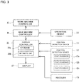
FIG. 3 is a block diagram illustrating a control system provided in the revolving work vehicle. -
FIG. 4 is a left view conceptually illustrating a coordinate system and the revolving work vehicle. -
FIG. 5 is a plan view conceptually illustrating the coordinate system and the revolving work vehicle. -
FIG. 6 is a plan view conceptually illustrating the coordinate system and the revolving work vehicle. - A description will hereinafter be made on an embodiment of the present invention with reference to the drawings.
- As illustrated in
FIGs. 1 and2 , a revolvingwork vehicle 1 includes: abase carrier 2, a revolvingsuperstructure 3 provided above thebase carrier 2 in a manner capable of revolving; aboom bracket 4 that is a swing body supported by the revolvingsuperstructure 3 in a manner capable of rotating horizontally; and awork machine 5 that is supported by theboom bracket 4 in a manner capable of rotating vertically. The revolvingwork vehicle 1 is configured as a shovel (a backhoe) with a boom swing function. In general, the boom swing function is provided in a mini-shovel, for which workability in a small area is requested. - The
base carrier 2 is driven when receiving power from anengine 30, and thereby drives or rotates the revolvingwork vehicle 1. Thebase carrier 2 includes: a pair of right andleft crawlers left travel motors crawlers base 23 is provided to support the revolvingsuperstructure 3 in a manner to allow free revolution thereof. Thebase carrier 2 is also provided with: a pair ofblade arms blade 25 as an earth removing plate that extends in a right-left direction between tips of theblade arms blade cylinder 26 for vertically rotating theblade 25. - The revolving
superstructure 3 is configured to be able to revolve around an axis that extends vertically at a center thereof. InFIGs. 1 and2 , a Z-axis that matches the axis is illustrated. The revolvingsuperstructure 3 is substantially formed in a disc shape in a plan view and can revolve within a lateral width of the base carrier 2 (a space between an outer end edge of theleft crawler 21 and an outer end edge of the right crawler 21). Theengine 30, acounterweight 31, acabin 32, and the like are disposed in the revolvingsuperstructure 3. A driver section surrounded by thecabin 32 is equipped with: a driver's seat (not illustrated) on which an operator is seated; an operation device 33 (seeFIG. 3 ) operated by the operator; a display 37 (seeFIG. 3 ) that shows various types of information; and the like. - The
boom bracket 4 is attached to a front end of the revolvingsuperstructure 3 via astay 33. Thestay 33 is provided with apivot pin 40, an axis a (seeFIG. 4 ) of which is oriented vertically. Theboom bracket 4 is supported in a manner to be freely and horizontally rotatable about the pivot pin 40 (that is, freely swingable to the right and left). Theboom bracket 4 rotates on a horizontal plane that is orthogonal to the axis a (for example, an X-Y plane illustrated inFIG. 5 ). Between the revolvingsuperstructure 3 and theboom bracket 4, aswing cylinder 41 is provided to extend/contract longitudinally. Theboom bracket 4 is actuated for the horizontal rotation according to the extension/contraction of theswing cylinder 41. - The
work machine 5 is driven when receiving the power from theengine 30, and thereby performs earth excavation work and the like according to an operation in the driver section. Thework machine 5 is supported in a vertically rotatable manner by theboom bracket 4. Theboom bracket 4 is provided with apivot pin 60, an axis of which is oriented horizontally. A base end of the work machine 5 (a base end of aboom 6, which will be described below) is supported in a manner to be freely and vertically rotatable about thepivot pin 60. Thework machine 5 rotates on a vertical plane (for example, an X-Z plane illustrated inFIG. 4 ) that is orthogonal to the axis of thepivot pin 60. In addition, thework machine 5 can perform the swing operation in an interlocking manner with the horizontal rotation of theboom bracket 4. - The
work machine 5 has theboom 6, anarm 7, and a work attachment, and the working end is included in the work attachment. In the present embodiment, theexcavation bucket 8 is attached as the work attachment, and ablade edge 8E serves as the working end. Theboom 6 is attached to theboom bracket 4 in a vertically rotatable manner. Theboom 6 extends vertically from the base end that is supported by theboom bracket 4, and is bent in a boomerang shape in a side view. Between theboom bracket 4 and an intermediate portion of theboom 6, aboom cylinder 6a that can move in a freely extendable/contractable manner is provided. A boom against theboom bracket 4 The vertical rotation of 6 operates according to the expansion and contraction of theboom cylinder 6a. Theboom 6 is actuated for the vertical rotation with respect to theboom bracket 4 according to the extension/contraction of theboom cylinder 6a. - The
arm 7 is attached in a vertically rotatable manner to theboom 6. At a tip of theboom 6, apivot pin 70 is provided such that an axis thereof is oriented horizontally. A base end of thearm 7 is supported is a manner to be freely and vertically rotatable (longitudinally rotatable) about thepivot pin 70. Between the intermediate portion of theboom 6 and the base end of thearm 7, anarm cylinder 7a is provided to move in a freely extendable/contractable manner. Thearm 7 is actuated for the vertical rotation with respect to theboom 6 according to the extension/contraction of thearm cylinder 7a. - The
bucket 8 is attached in a vertically rotatable manner to thearm 7. At a tip of thearm 7, apivot pin 80 is provided such that an axis thereof is oriented horizontally. A base end of thebucket 8 is supported is a manner to be freely and vertically rotatable (longitudinally rotatable) about thepivot pin 80. Abucket link 81 is interposed between the tip of thearm 7 and thebucket 8. Thebucket link 81 is configured as a link that transmits drive power to thebucket 8. Between thebucket link 81 and the base end of thearm 7, abucket cylinder 8a is provided to move in a freely extendable/contractable manner. Thebucket 8 is actuated for the vertical rotation with respect to thearm 7 according to the extension/contraction of thebucket cylinder 8a. - A brief description will be made on an example of a control system provided in the revolving
work vehicle 1. As illustrated inFIG. 3 , this revolvingwork vehicle 1 includes theoperation device 33, amain machine controller 34 as a vehicle control device, and awork machine controller 35, adisplay controller 36 as a display control device, and thedisplay 37. Theoperation device 33 includes a lever, a switch, a pedal, an operation panel, and the like. Based on a control signal from theoperation device 33, themain machine controller 34 controls travel operation of thebase carrier 2 and revolving operation of the revolvingsuperstructure 3. In addition, based on a control signal from theoperation device 33, themain machine controller 34 controls thework machine controller 35 and thedisplay controller 36. - The
work machine controller 35 controls operation of thework machine 5. This operation includes not only the vertical rotation of each of theboom 6, thearm 7, and thebucket 8 but also the horizontal rotation of theboom bracket 4 for the swing operation of thework machine 5. Thedisplay controller 36 includes: astorage 36a that is constructed with random-access memory (RAM), read-only memory (ROM), and the like; and anarithmetic unit 36b that is constructed with a central processing unit (CPU) and the like. Thestorage 36a stores various types of data as will be described below. Thearithmetic unit 36b executes specified arithmetic processing on the basis of the data stored in thestorage 36a, detection signals fromposition detecting devices display controller 36 can display a result of the arithmetic processing on thedisplay 37. - Next, a description will be made on a method for detecting a position of the
blade edge 8E of thebucket 8 as the working end. As illustrated inFIG. 3 , the revolvingwork vehicle 1 includes the position detecting device 11 (a first position detecting device) and the position detecting device 12 (a second position detecting device). Theposition detecting device 11 detects a horizontal position of theboom bracket 4 with respect to the revolvingsuperstructure 3. Theposition detecting device 12 detects a vertical position of thework machine 5 with respect to the revolvingsuperstructure 3. The revolvingwork vehicle 1 also includes thearithmetic unit 36b that calculates a position of theblade edge 8E based on results of detection by theseposition detecting devices - In the present embodiment, the
position detecting device 11 includes a position sensor that is installed on theboom bracket 4 as illustrated inFIG. 2 . The position sensor detects movement on the plane on which theboom bracket 4 is movable, more specifically, movement on the horizontal plane that is orthogonal to the axis a of thepivot pin 40. By installing such a position sensor on theboom bracket 4, it is possible to relatively easily detect the horizontal position of theboom bracket 4 with respect to the revolvingsuperstructure 3. In the present embodiment, an example in which an acceleration sensor is used as the position sensor constituting theposition detecting device 11 so as to detect a swing angle θ2 of theboom bracket 4 with respect to the revolvingsuperstructure 3 will be described. - The position sensor that constitutes the
position detecting device 11 can also be installed in theswing cylinder 41. As the position sensor, an inertial sensor such as the acceleration sensor can be used as described above. However, the position sensor is not limited thereto. For example, a gyro sensor, an angle sensor (a tilt sensor), or a cylinder sensor (a stroke sensor) can also be used. In the case where the cylinder sensor is used, the swing angle θ2 is detected on the basis of an extension/contraction amount (a stroke amount) of theswing cylinder 41. In this way, it is possible to detect the horizontal position of theboom bracket 4 with respect to the revolvingsuperstructure 3. - In the present embodiment, the
position detecting device 12 includes: aposition sensor 12a that is installed on theboom 6 as illustrated inFIG. 1 ; aposition sensor 12b that is installed on thearm 7; and aposition sensor 12c that is installed on thebucket link 81. Each of theposition sensors 12a to 12c detects movement on a plane on which thework machine 5 is movable, more specifically, movement on the vertical plane including the axis a of thepivot pin 40. In the present embodiment, an example in which the acceleration sensors are used as theposition sensors 12a to 12c so as to detect angles α, β, γ will be described below. Similar to theposition detecting device 11, the position sensor that constitutes theposition detecting device 12 is not limited to the inertial sensor such as the acceleration sensor. -
FIG. 4 is a left view conceptually illustrating the coordinate system and the revolvingwork vehicle 1. This coordinate system is an orthogonal coordinate system defined by: an X-axis in the horizontal direction extending to the right and left inFIG. 4 ; a Y-axis (seeFIG. 5 ) in the horizontal direction that is orthogonal to the sheet ofFIG. 4 ; and a Z-axis in the vertical direction extending vertically inFIG. 4 . The X-axis extends in a front-rear direction of thebase carrier 2, and the Y-axis extends in the right-left direction (a width direction) of thebase carrier 2. The Z-axis matches the axis that is the center of revolution of the revolvingsuperstructure 3. The X-Y plane including an origin O is located at a height of the axis of thepivot pin 60, and the axis a of thepivot pin 40 crosses the X-Y plane at a right angle. -
FIG. 5 is a plan view conceptually illustrating the coordinate system and the revolvingwork vehicle 1. The position of thework machine 5 illustrated inFIG. 4 is indicated by a chain line inFIG. 5 . InFIGs. 4 and5 , the axis a of thepivot pin 40 is located on the X-axis. This state is set as a reference of a revolution angle θ1 (seeFIG. 6 ) of the revolvingsuperstructure 3 with respect to thebase carrier 2, and the revolution angle θ1 is zero inFIGs. 4 and5 . In addition, inFIG. 4 , thework machine 5 is arranged on the vertical plane (the X-Z plane) that includes the axis a of thepivot pin 40 and the Z axis. This state is set as a reference of the swing angle θ2 of theboom bracket 4 with respect to the revolvingsuperstructure 3, and the swing angle θ2 is zero inFIG. 4 . - In
FIG. 4 , thework machine 5 is in a movable state on the X-Z plane, that is, each of theboom 6, thearm 7, and thebucket 8 is in a state capable of rotating vertically (rotating longitudinally) on the X-Z plane. The angle α is a tilt angle (a rotation angle) of theboom 6 with the axis a of thepivot pin 40 being a reference. The angle β is a tilt angle (a rotation angle) of thearm 7 with an extending direction of the boom 6 (a direction of a length L1) being a reference. The angle γ is a tilt angle (a rotation angle) of thebucket 8 with an extending direction of the arm 7 (a direction of a length L2) being a reference. As it has already been described, these angles α, β, γ can respectively be detected by theposition sensors 12a to 12c that constitute theposition detecting device 12. - The length L1 is a length from the base end to the tip of the
boom 6, more specifically, corresponds to a linear distance from the axis of thepivot pin 60 to the axis of thepivot pin 70. The length L2 is a length from the base end to the tip of thearm 7, more specifically, corresponds to a linear distance from the axis of thepivot pin 70 to the axis of thepivot pin 80. A length L3 is a length from the base end to the tip of thebucket 8, more specifically, corresponds to a linear distance from the axis of thepivot pin 80 to theblade edge 8E. Data on the lengths L1 to L3 is stored in thestorage 36a in advance. - The revolving
work vehicle 1 in the present embodiment includes twoGPS antennas FIG. 3 ) receives three-dimensional position information of theantennas antennas work vehicle 1. In the present embodiment, theantennas superstructure 3 to theantennas work vehicle 1 or measurement in advance, and data thereon is stored in thestorage 36a. - Similar to
FIG. 5 ,FIG. 6 is a plan view conceptually illustrating the coordinate system and the revolvingwork vehicle 1, but differs fromFIG. 5 in a point that the revolvingsuperstructure 3 revolves. InFIG. 6 , the position of thework machine 5 at the time when the swing angle θ2 is zero is indicated by a chain line. Since a revolution radius r of the axis a can be comprehended in advance, the data thereon is stored in thestorage 36a. The revolution angle θ1 of the revolvingsuperstructure 3 with respect to thebase carrier 2 can be calculated on the basis of the three-dimensional position information of theantennas storage 36a, and processing thereof is executed by thearithmetic unit 36b. As long as information required for the calculation of the revolution angle θ1 is acquired, installation positions of theantennas work vehicle 1 are not particularly limited. - First, as indicated by the chain lines in
FIG. 4 andFIG. 5 , in a state where the revolvingsuperstructure 3 does not revolve and thework machine 5 does not swing (that is, θ1 = 0, θ2 = 0), when three-dimensional coordinates of theblade edge 8E with the position of the axis a on the X-Y plane being set as a base point are set as (Xa, Ya, Za), such coordinates (Xa, Ya, Za) can be calculated by the following formulas.

- Next, as indicated by a solid line in
FIG. 5 , in a state where the revolvingsuperstructure 3 does not revolve and thework machine 5 swings (that is, θ1 = 0, θ2 ≠ 0), when the three-dimensional coordinates of theblade edge 8E with the position of the axis a on the X-Y plane being set as the base point are set as (Xa1, Ya1, Za1), such coordinates (Xa1, Ya1, Za1) can be calculated by the following formulas.


- Then, as illustrated in
FIG. 6 , in a state where the revolvingsuperstructure 3 revolves (θ1 ≠ 0), when three-dimensional coordinates of the axis a with the origin O on the X-Y plane being a base point is set as (X ○ 0, Y ○ 0, Z ○ 0) and the revolution radius of the axis a is set as r, such coordinates (X ○ 0, Y ○ 0, Z ○ 0) can be calculated by the following formulas.

- Thereafter, as indicated by the chain line in
FIG. 6 , in a state where the revolvingsuperstructure 3 revolves and thework machine 5 does not swing (θ1 ≠ 0, θ2 = 0), when the three-dimensional coordinates of theblade edge 8E with the origin O on the X-Y plane being the base point is set as (X ○ 1, Y ○ 1, Z ○ 1), such coordinates (X ○ 1, Y ○ 1, Z ○ 1) can be calculated by the following formulas.


- Furthermore, as indicated by a solid line in
FIG. 6 , in a state where the revolvingsuperstructure 3 revolves and thework machine 5 swings (θ1 ≠ 0, θ2 ≠ 0), when the three-dimensional coordinates of theblade edge 8E with the origin O on the X-Y plane being the base point is set as (X ○ 2, Y ○ 2, Z ○ 2), such coordinates (X ○ 2, Y ○ 2, Z ○ 2) can be calculated by the following formulas.


- Thus, when the global coordinates of the origin O are set as (A, B, C), by converting the three-dimensional coordinates (X ○ 2, Y ○ 2, Z ○ 2) of the
blade edge 8E by the following formulas, the global coordinates (Xg2, Yg2, Zg2) of theblade edge 8E can be calculated.


- As described above, in the present embodiment, the horizontal position of the
boom bracket 4 with respect to the revolving superstructure 3 (and thus the swing angle θ2) is detected by theposition detecting device 11, the vertical direction of thework machine 5 with respect to the revolving superstructure 3 (and thus is the angles α, β, γ) is detected by theposition detecting device 12, and the position of theblade edge 8E calculated based on those results of detection. Thearithmetic unit 36b executes such arithmetic processing with appropriate reference to the data stored in thestorage 36a and the information sent from thereceiver 19. The calculation result can be notified to the operator by showing the calculation result on thedisplay 37, for example. - As it has been described so far, according to the present embodiment, it is possible to detect the position of the
blade edge 8E, which is the working end of thework machine 5, in the revolvingwork vehicle 1, that has a boom swing function, with a high degree of accuracy. - In the present embodiment, an example in which the three-dimensional position of the working end is calculated has been described. However, a two-dimensional position thereof may be calculated. For example, such a display system for the hydraulic shovel has conventionally been known. The display system shows a mutual positional relationship between a work line (a target excavation line) and the working end as a two-dimensional image and thereby allows the operator to appropriately excavate a required place. The present invention can be applied to such a display system in order to display the working end. In such a display system, the work line can be created by setting the working end of the work machine as a work start point. Thus, it is not necessary to use the global coordinates, and the GPS antennas can be eliminated. In such a case, it may be configured that the revolution angle of the revolving superstructure with respect to the base carrier is detected by the position sensor (for example, the angle sensor) installed on the revolving superstructure.
- The present invention is not limited to the above-described embodiment in any respect, and various improvements and modifications can be made thereto within the scope that does not depart from the gist of the present invention.
-
- 1
- Revolving work vehicle
- 2
- Base carrier
- 3
- Revolving superstructure
- 4
- Boom bracket (swing body)
- 5
- Work machine
- 6
- Boom
- 7
- Arm
- 8
- Bucket (work attachment)
- 8a
- Bucket cylinder
- 8E
- Blade edge (working end)
- 11
- First position detecting device
- 12
- Second position detecting device
- 36b
- Arithmetic unit
Claims (4)
- A revolving work vehicle comprising:a base carrier;a revolving superstructure provided above the base carrier in a manner capable of revolving;a swing body supported by the revolving superstructure in a horizontally rotatable manner;a work machine supported by the swing body in a vertically rotatable manner;a first position detecting device that detects a horizontal position of the swing body with respect to the revolving superstructure;a second position detecting device that detects a vertical position of the work machine with respect to the revolving superstructure; andan arithmetic unit that calculates a position of a working end of the work machine based on results of detection by the first and second position detecting devices.
- The revolving work vehicle according to claim 1, wherein
the first position detecting device includes a position sensor that is installed on the swing body. - The revolving work vehicle according to claim 1 or 2, wherein
the work machine includes: a boom that is attached in a vertically rotatable manner to the swing body; an arm that is attached in a vertically rotatable manner to the boom; and a work attachment that is attached in a vertically rotatable manner to the arm, the working end being included in the work attachment, and
the second position measuring device includes: a position sensor that is installed on the boom; a position sensor that is installed on the arm; and a position sensor that is installed on a link for transmitting drive power to the work attachment. - A method for detecting a position of a working end of a revolving work vehicle, the method being used for the revolving work vehicle including: a revolving superstructure provided above a base carrier in a manner capable of revolving; a swing body supported by the revolving superstructure in a horizontally rotatable manner; and a work machine supported by the swing body in a vertically rotatable manner, the method for detecting the position of the working end of the revolving work vehicle comprising:detecting a horizontal position of the swing body with respect to the revolving superstructure by a first position detecting device;detecting a vertical position of the work machine with respect to the revolving superstructure by a second position detecting device; andcalculating the position of the working end of the work machine based on results of detection by the first and second position detecting devices.
Applications Claiming Priority (2)
| Application Number | Priority Date | Filing Date | Title |
|---|---|---|---|
| JP2018045415A JP6889675B2 (en) | 2018-03-13 | 2018-03-13 | Method of detecting the position of the construction end of a turning work vehicle and a turning work vehicle |
| PCT/JP2019/002156 WO2019176314A1 (en) | 2018-03-13 | 2019-01-24 | Revolving work vehicle, and method for detecting position of working end of revolving work vehicle |
Publications (2)
| Publication Number | Publication Date |
|---|---|
| EP3767043A1 true EP3767043A1 (en) | 2021-01-20 |
| EP3767043A4 EP3767043A4 (en) | 2021-12-22 |
Family
ID=67907704
Family Applications (1)
| Application Number | Title | Priority Date | Filing Date |
|---|---|---|---|
| EP19767524.2A Pending EP3767043A4 (en) | 2018-03-13 | 2019-01-24 | ROTATION CONSTRUCTION VEHICLE AND METHOD OF DETECTION OF THE WORKING END POSITION OF A ROTATION CONSTRUCTION VEHICLE |
Country Status (4)
| Country | Link |
|---|---|
| US (2) | US11674289B2 (en) |
| EP (1) | EP3767043A4 (en) |
| JP (1) | JP6889675B2 (en) |
| WO (1) | WO2019176314A1 (en) |
Families Citing this family (3)
| Publication number | Priority date | Publication date | Assignee | Title |
|---|---|---|---|---|
| JP7039451B2 (en) * | 2018-12-25 | 2022-03-22 | 株式会社クボタ | Working machine |
| JP7134922B2 (en) * | 2019-06-19 | 2022-09-12 | 株式会社クボタ | work machine |
| JP7040810B2 (en) * | 2020-01-08 | 2022-03-23 | 株式会社ワイビーエム | Construction position guidance system for ground improvement machines |
Family Cites Families (14)
| Publication number | Priority date | Publication date | Assignee | Title |
|---|---|---|---|---|
| JP2629086B2 (en) * | 1991-05-10 | 1997-07-09 | 株式会社クボタ | Backhoe |
| JP5046218B2 (en) | 2000-12-14 | 2012-10-10 | 株式会社トプコン | Position detection method and apparatus using GPS in construction machine for civil engineering |
| JP2002181538A (en) * | 2000-12-14 | 2002-06-26 | Topcon Corp | Construction edge position detection device using GPS |
| US6782644B2 (en) * | 2001-06-20 | 2004-08-31 | Hitachi Construction Machinery Co., Ltd. | Remote control system and remote setting system for construction machinery |
| US8739354B2 (en) * | 2002-03-11 | 2014-06-03 | Lynn A. Buckner | Mobile method for servicing or cleaning a utility sewer or drainage pipe |
| CN101413279B (en) * | 2008-11-29 | 2011-06-08 | 湖南山河智能机械股份有限公司 | Electromechanical integrated digging loader and control method thereof |
| US8768581B2 (en) * | 2010-05-24 | 2014-07-01 | Hitachi Construction Machinery Co., Ltd. | Work machine safety device |
| JP5059954B2 (en) * | 2011-02-22 | 2012-10-31 | 株式会社小松製作所 | Excavator display system and control method thereof. |
| US8498787B2 (en) * | 2011-05-27 | 2013-07-30 | Caterpillar Trimble Control Technologies Llc | Method and system for monitoring the operation of a cable shovel machine |
| DE102013221302A1 (en) * | 2013-10-21 | 2015-04-23 | Mts Maschinentechnik Schrode Ag | Construction machinery |
| EP3015625A1 (en) * | 2014-10-31 | 2016-05-04 | CIFA SpA | Method and apparatus to move an articulated arm |
| JP2016098637A (en) * | 2014-11-26 | 2016-05-30 | 日立建機株式会社 | Angle detector for work device |
| JP6333712B2 (en) * | 2014-12-12 | 2018-05-30 | 株式会社日立建機ティエラ | Excavator |
| JP6289534B2 (en) * | 2016-05-09 | 2018-03-07 | 株式会社小松製作所 | Work machine control system and work machine |
-
2018
- 2018-03-13 JP JP2018045415A patent/JP6889675B2/en active Active
-
2019
- 2019-01-24 EP EP19767524.2A patent/EP3767043A4/en active Pending
- 2019-01-24 US US16/975,969 patent/US11674289B2/en active Active
- 2019-01-24 WO PCT/JP2019/002156 patent/WO2019176314A1/en not_active Ceased
-
2023
- 2023-04-28 US US18/309,130 patent/US20230257967A1/en active Pending
Also Published As
| Publication number | Publication date |
|---|---|
| EP3767043A4 (en) | 2021-12-22 |
| US20200399868A1 (en) | 2020-12-24 |
| US11674289B2 (en) | 2023-06-13 |
| WO2019176314A1 (en) | 2019-09-19 |
| US20230257967A1 (en) | 2023-08-17 |
| JP6889675B2 (en) | 2021-06-18 |
| JP2019157493A (en) | 2019-09-19 |
Similar Documents
| Publication | Publication Date | Title |
|---|---|---|
| US20230257967A1 (en) | Revolving work vehicle, and method for detecting position of working end of revolving work vehicle | |
| US20240254730A1 (en) | Display system of turning work vehicle | |
| AU2021201894B2 (en) | Shape measuring system and shape measuring method | |
| CN103917717B (en) | The excavation control apparatus of hydraulic crawler excavator | |
| CN113167052B (en) | Working machine | |
| JP6900897B2 (en) | Obstacle detector for construction machinery | |
| KR20160140332A (en) | Control system of work machine and work machine | |
| CN115698434B (en) | Information acquisition system and information acquisition method | |
| US12123170B2 (en) | Intrusion monitoring control system and work machine | |
| KR20230136210A (en) | Position estimation systems, position estimation units, working machines, and extension units | |
| CN117836488A (en) | System and method for controlling a work machine | |
| AU2021255285B2 (en) | Construction method and construction system | |
| CN117795165A (en) | Systems and methods for controlling work machinery | |
| JP2023128874A (en) | Information calibration method | |
| JP2025114922A (en) | Measurement system for work machine and measurement method for work machine | |
| WO2024070333A1 (en) | Construction machine | |
| JP2022128423A (en) | System and method for acquiring shape data indicating shape of work device in work machine having work device |
Legal Events
| Date | Code | Title | Description |
|---|---|---|---|
| STAA | Information on the status of an ep patent application or granted ep patent |
Free format text: STATUS: THE INTERNATIONAL PUBLICATION HAS BEEN MADE |
|
| PUAI | Public reference made under article 153(3) epc to a published international application that has entered the european phase |
Free format text: ORIGINAL CODE: 0009012 |
|
| STAA | Information on the status of an ep patent application or granted ep patent |
Free format text: STATUS: REQUEST FOR EXAMINATION WAS MADE |
|
| 17P | Request for examination filed |
Effective date: 20200929 |
|
| AK | Designated contracting states |
Kind code of ref document: A1 Designated state(s): AL AT BE BG CH CY CZ DE DK EE ES FI FR GB GR HR HU IE IS IT LI LT LU LV MC MK MT NL NO PL PT RO RS SE SI SK SM TR |
|
| AX | Request for extension of the european patent |
Extension state: BA ME |
|
| DAV | Request for validation of the european patent (deleted) | ||
| DAX | Request for extension of the european patent (deleted) | ||
| A4 | Supplementary search report drawn up and despatched |
Effective date: 20211119 |
|
| RIC1 | Information provided on ipc code assigned before grant |
Ipc: E02F 9/20 20060101ALI20211115BHEP Ipc: E02F 9/26 20060101AFI20211115BHEP |
|
| STAA | Information on the status of an ep patent application or granted ep patent |
Free format text: STATUS: EXAMINATION IS IN PROGRESS |
|
| 17Q | First examination report despatched |
Effective date: 20240125 |