EP3766782A1 - Active aircraft probe heat monitor and method of use - Google Patents
Active aircraft probe heat monitor and method of use Download PDFInfo
- Publication number
- EP3766782A1 EP3766782A1 EP19213983.0A EP19213983A EP3766782A1 EP 3766782 A1 EP3766782 A1 EP 3766782A1 EP 19213983 A EP19213983 A EP 19213983A EP 3766782 A1 EP3766782 A1 EP 3766782A1
- Authority
- EP
- European Patent Office
- Prior art keywords
- aircraft
- power demand
- probe
- ice system
- air data
- Prior art date
- Legal status (The legal status is an assumption and is not a legal conclusion. Google has not performed a legal analysis and makes no representation as to the accuracy of the status listed.)
- Granted
Links
Images

Classifications
-
- B—PERFORMING OPERATIONS; TRANSPORTING
- B64—AIRCRAFT; AVIATION; COSMONAUTICS
- B64D—EQUIPMENT FOR FITTING IN OR TO AIRCRAFT; FLIGHT SUITS; PARACHUTES; ARRANGEMENT OR MOUNTING OF POWER PLANTS OR PROPULSION TRANSMISSIONS IN AIRCRAFT
- B64D15/00—De-icing or preventing icing on exterior surfaces of aircraft
- B64D15/20—Means for detecting icing or initiating de-icing
- B64D15/22—Automatic initiation by icing detector
-
- G—PHYSICS
- G05—CONTROLLING; REGULATING
- G05D—SYSTEMS FOR CONTROLLING OR REGULATING NON-ELECTRIC VARIABLES
- G05D23/00—Control of temperature
- G05D23/19—Control of temperature characterised by the use of electric means
-
- B—PERFORMING OPERATIONS; TRANSPORTING
- B64—AIRCRAFT; AVIATION; COSMONAUTICS
- B64D—EQUIPMENT FOR FITTING IN OR TO AIRCRAFT; FLIGHT SUITS; PARACHUTES; ARRANGEMENT OR MOUNTING OF POWER PLANTS OR PROPULSION TRANSMISSIONS IN AIRCRAFT
- B64D15/00—De-icing or preventing icing on exterior surfaces of aircraft
- B64D15/12—De-icing or preventing icing on exterior surfaces of aircraft by electric heating
-
- B—PERFORMING OPERATIONS; TRANSPORTING
- B64—AIRCRAFT; AVIATION; COSMONAUTICS
- B64D—EQUIPMENT FOR FITTING IN OR TO AIRCRAFT; FLIGHT SUITS; PARACHUTES; ARRANGEMENT OR MOUNTING OF POWER PLANTS OR PROPULSION TRANSMISSIONS IN AIRCRAFT
- B64D15/00—De-icing or preventing icing on exterior surfaces of aircraft
- B64D15/20—Means for detecting icing or initiating de-icing
-
- B—PERFORMING OPERATIONS; TRANSPORTING
- B64—AIRCRAFT; AVIATION; COSMONAUTICS
- B64D—EQUIPMENT FOR FITTING IN OR TO AIRCRAFT; FLIGHT SUITS; PARACHUTES; ARRANGEMENT OR MOUNTING OF POWER PLANTS OR PROPULSION TRANSMISSIONS IN AIRCRAFT
- B64D43/00—Arrangements or adaptations of instruments
- B64D43/02—Arrangements or adaptations of instruments for indicating aircraft speed or stalling conditions
-
- G—PHYSICS
- G01—MEASURING; TESTING
- G01K—MEASURING TEMPERATURE; MEASURING QUANTITY OF HEAT; THERMALLY-SENSITIVE ELEMENTS NOT OTHERWISE PROVIDED FOR
- G01K1/00—Details of thermometers not specially adapted for particular types of thermometer
- G01K1/20—Compensating for effects of temperature changes other than those to be measured, e.g. changes in ambient temperature
-
- G—PHYSICS
- G01—MEASURING; TESTING
- G01P—MEASURING LINEAR OR ANGULAR SPEED, ACCELERATION, DECELERATION, OR SHOCK; INDICATING PRESENCE, ABSENCE, OR DIRECTION, OF MOVEMENT
- G01P13/00—Indicating or recording presence, absence, or direction, of movement
- G01P13/02—Indicating direction only, e.g. by weather vane
- G01P13/025—Indicating direction only, e.g. by weather vane indicating air data, i.e. flight variables of an aircraft, e.g. angle of attack, side slip, shear, yaw
-
- G—PHYSICS
- G01—MEASURING; TESTING
- G01P—MEASURING LINEAR OR ANGULAR SPEED, ACCELERATION, DECELERATION, OR SHOCK; INDICATING PRESENCE, ABSENCE, OR DIRECTION, OF MOVEMENT
- G01P5/00—Measuring speed of fluids, e.g. of air stream; Measuring speed of bodies relative to fluids, e.g. of ship, of aircraft
- G01P5/14—Measuring speed of fluids, e.g. of air stream; Measuring speed of bodies relative to fluids, e.g. of ship, of aircraft by measuring differences of pressure in the fluid
- G01P5/16—Measuring speed of fluids, e.g. of air stream; Measuring speed of bodies relative to fluids, e.g. of ship, of aircraft by measuring differences of pressure in the fluid using Pitot tubes, e.g. Machmeter
- G01P5/165—Arrangements or constructions of Pitot tubes
-
- H—ELECTRICITY
- H05—ELECTRIC TECHNIQUES NOT OTHERWISE PROVIDED FOR
- H05B—ELECTRIC HEATING; ELECTRIC LIGHT SOURCES NOT OTHERWISE PROVIDED FOR; CIRCUIT ARRANGEMENTS FOR ELECTRIC LIGHT SOURCES, IN GENERAL
- H05B1/00—Details of electric heating devices
- H05B1/02—Automatic switching arrangements specially adapted to apparatus ; Control of heating devices
Definitions
- the present disclosure relates to aircraft surface device heaters, and more particularly to probe heat monitors and a method of use.
- the conventional methods and systems have generally been considered satisfactory for their intended purpose, but with recent industry development, regulatory bodies have begun requiring a more reliable aircraft probe.
- the purpose of this disclosure is to ensure sufficient heating performance to maintain intended operation in the specific condition encountered at that time.
- FIG. 1 a partial view of an exemplary embodiment of an air data probe monitoring system in accordance with the disclosure is shown in Fig. 1 and is designated generally by reference character 100.
- FIG. 2 Other aspects of the method in accordance with the disclosure, or aspects thereof, are provided in Fig. 2 , as will be described.
- the methods and systems of the disclosure can be used to accurately determine if aircraft probe heaters are providing sufficient power to operate as intended in the specific conditions being flown through at that time.
- Fig. 1 shows a system 100 for ensuring proper functionality of a self-compensating heater 103 of an air-data probe 102.
- the system 100 includes a device 102 having a first surface 105 exposed to airflow about an exterior of an aircraft 110.
- the device includes a self-compensating heater 103 configured to heat the device, which can be an air-data probe 102 in order to ensure proper measurements are being recorded by the air-data probe 102, and the air-data probe 102 is not being compromised by potential ice buildup.
- the system 100 further includes power monitoring equipment such as current monitors 106 to measure values representing electrical current flow in and out of air data probe 102 through the self-compensating heater 103.
- the system 100 also includes a processor 108, and computer-readable memory 112 encoded with instructions that, when executed by the processor 108, cause the processor 108 to receive an air data parameter and atmospheric conditions surrounding the aircraft 110, calculate an expected power demand of the self-compensating heater based on the air data parameters and the atmospheric conditions, and compare the actual power demand of the self-compensating heater 103 to the expected power demand from the air data parameter and atmospheric conditions received by the processor 108. A corrective action is demanded by the system if the actual power demand and the expected power demand differ by more than an acceptable amount.
- the corrective action taken or required by the processor 108 can include changing the power supplied to the self-compensating heater 103 by increasing the power in order to avoid icing over the aircraft probe 102, or decreasing the power supplied in order to prevent overheating and damaging the aircraft probe 102. It is also considered that the corrective action can include removing or servicing the aircraft probe 102 when the aircraft 110 has landed. Corrective action can also include removing the aircraft probe 102 from a voting arrangement that includes at least one other aircraft probe 102, indicating the failure of subject probe, and using only other aircraft probe sensors in order to provide the appropriate data to the aircraft.
- Fig. 2 shows a flow diagram for a method of controlling the system described above.
- the method includes providing power 202 to an anti-ice system in order to heat the data probe, monitoring 204 an actual power demand of the anti-ice system, and monitoring and collecting 206 an air data parameter and atmospheric conditions surrounding the aircraft and calculating 208 an expected power demand of the anti-ice system given the air data parameters and the atmospheric conditions.
Landscapes
- Engineering & Computer Science (AREA)
- Aviation & Aerospace Engineering (AREA)
- Physics & Mathematics (AREA)
- General Physics & Mathematics (AREA)
- Automation & Control Theory (AREA)
- Air Conditioning Control Device (AREA)
- Management, Administration, Business Operations System, And Electronic Commerce (AREA)
- Arrangements For Transmission Of Measured Signals (AREA)
Abstract
Description
- The present disclosure relates to aircraft surface device heaters, and more particularly to probe heat monitors and a method of use.
- Typical aircraft probe heat monitoring systems today look at the current draw through the heater circuit and can trigger when that current falls below a certain value. However, this method is only sufficient if an open circuit or a gross short occurs within the system and the heater circuit experiences a significant reduction in power. Due to the self-compensating nature of many aircraft probe heaters, the trigger level cannot be set at a current of sufficiently high accuracy to warn of conditions where current flow has only been slightly degraded. It is possible that current is flowing above the trigger level, but not enough current is flowing to maintain safe operation in severe icing conditions, especially if conditions suddenly change.
- The conventional methods and systems have generally been considered satisfactory for their intended purpose, but with recent industry development, regulatory bodies have begun requiring a more reliable aircraft probe. The purpose of this disclosure is to ensure sufficient heating performance to maintain intended operation in the specific condition encountered at that time.
- A method includes providing power to an aircraft probe anti-ice system, monitoring an actual power demand of the aircraft probe anti-ice system, monitoring an air data parameter and atmospheric conditions surrounding an aircraft and calculating an expected power demand of the aircraft probe anti-ice system based on the air data parameters and the atmospheric conditions, comparing the actual power demand of the aircraft probe anti-ice system to the expected power demand, performing a corrective action if the actual power demand and the expected power demand are different by more than an acceptable amount. The air data parameters can include airspeed, total air temperature, altitude, angle of attack, and angle of sideslip. The atmospheric conditions can include temperature, ice water content and liquid water content. The anti-ice system can include a self-compensating heater.
- The corrective actions can include changing the power supplied to the probe anti-ice system, removing the probe from the aircraft, removing the aircraft probe data from a voting arrangement, or notifying the pilots and/or aircraft systems that the subject aircraft probe data may not be reliable.
- A system includes a device having a first surface configured to be exposed to airflow about an exterior of an aircraft, the device including a first self-compensating heater configured to heat the first surface, at least one current monitor configured to produce a first measurement value representing electrical current flow in and out of the first self-compensating heater, one or more processors, and computer-readable memory encoded with instructions that, when executed by the one or more processors, cause the system to: receive air data parameters and atmospheric conditions surrounding the aircraft, calculate an expected power demand of the self-compensating heater based on the air data parameters and the atmospheric conditions, compare the actual power demand of the self-compensating heater to the expected power demand, perform a corrective action if the actual power demand and the expected power demand are different by more than an acceptable amount.
- These and other features of the systems and methods of the subject disclosure will become more readily apparent to those skilled in the art from the following detailed description of the preferred embodiments taken in conjunction with the drawings.
- So that those skilled in the art to which the subject disclosure appertains will readily understand how to make and use the devices and methods of the subject disclosure without undue experimentation, preferred embodiments thereof will be described in detail herein below with reference to certain figures, wherein:
-
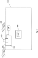
Fig. 1 is a block diagram of an air data system in accordance with the disclosure; and -
Fig. 2 is a block diagram of a method of using the air data system ofFig. 1 in accordance with the disclosure. - Reference will now be made to the drawings wherein like reference numerals identify similar structural features or aspects of the subject disclosure. For purposes of explanation and illustration, and not limitation, a partial view of an exemplary embodiment of an air data probe monitoring system in accordance with the disclosure is shown in
Fig. 1 and is designated generally byreference character 100. Other aspects of the method in accordance with the disclosure, or aspects thereof, are provided inFig. 2 , as will be described. The methods and systems of the disclosure can be used to accurately determine if aircraft probe heaters are providing sufficient power to operate as intended in the specific conditions being flown through at that time. -
Fig. 1 shows asystem 100 for ensuring proper functionality of a self-compensatingheater 103 of an air-data probe 102. Thesystem 100 includes adevice 102 having afirst surface 105 exposed to airflow about an exterior of anaircraft 110. The device includes a self-compensatingheater 103 configured to heat the device, which can be an air-data probe 102 in order to ensure proper measurements are being recorded by the air-data probe 102, and the air-data probe 102 is not being compromised by potential ice buildup. Thesystem 100 further includes power monitoring equipment such ascurrent monitors 106 to measure values representing electrical current flow in and out ofair data probe 102 through the self-compensatingheater 103. Thesystem 100 also includes aprocessor 108, and computer-readable memory 112 encoded with instructions that, when executed by theprocessor 108, cause theprocessor 108 to receive an air data parameter and atmospheric conditions surrounding theaircraft 110, calculate an expected power demand of the self-compensating heater based on the air data parameters and the atmospheric conditions, and compare the actual power demand of the self-compensatingheater 103 to the expected power demand from the air data parameter and atmospheric conditions received by theprocessor 108. A corrective action is demanded by the system if the actual power demand and the expected power demand differ by more than an acceptable amount. - The air data parameter includes but is not limited to airspeed, total air temperature, altitude, angle of attack, and angle of sideslip. The atmospheric conditions include but are not limited to temperature, ice water content and liquid water content. All of the parameters do not necessarily have to be used to calculate the expected power draw from the self-compensating heater. The expected power draw as a function of the air data parameters and atmospheric conditions can be stored on the computer
readable memory 112 prior to the flight and continuously compared to the actual power draw at that time. - The corrective action taken or required by the
processor 108 can include changing the power supplied to the self-compensatingheater 103 by increasing the power in order to avoid icing over theaircraft probe 102, or decreasing the power supplied in order to prevent overheating and damaging theaircraft probe 102. It is also considered that the corrective action can include removing or servicing theaircraft probe 102 when theaircraft 110 has landed. Corrective action can also include removing theaircraft probe 102 from a voting arrangement that includes at least oneother aircraft probe 102, indicating the failure of subject probe, and using only other aircraft probe sensors in order to provide the appropriate data to the aircraft. -
Fig. 2 shows a flow diagram for a method of controlling the system described above. The method includes providingpower 202 to an anti-ice system in order to heat the data probe, monitoring 204 an actual power demand of the anti-ice system, and monitoring and collecting 206 an air data parameter and atmospheric conditions surrounding the aircraft and calculating 208 an expected power demand of the anti-ice system given the air data parameters and the atmospheric conditions. Using a processor in order to compare 210 the actual power demand of the anti-ice system to the expected power demand, and performing or signaling to perform 212 a corrective action if the actual power demand and the expected power demand are different by more than an acceptable amount. - The methods and systems of the present disclosure, as described above and shown in the drawings, provide for an icing monitoring system with superior properties including increased reliability. While the apparatus and methods of the subject disclosure have been shown and described with reference to embodiments, those skilled in the art will readily appreciate that changes and/or modifications may be made thereto without departing from the scope of the invention as defined by the claims.
Claims (13)
- A method comprising:providing power to an aircraft anti-ice system;monitoring an actual power demand of the aircraft anti-ice system;calculating an expected power demand of the aircraft anti-ice system based on the air data parameters and the atmospheric conditions;comparing the actual power demand of the aircraft probe anti-ice system to the expected power demand; and performing a corrective action if the actual power demand and the expected power demand are different by more than a selected amount.
- The method of claim 1, further comprising monitoring an air data parameter and atmospheric conditions surrounding the aircraft.
- The method of claim 2, wherein the air data parameters include airspeed, total air temperature, altitude, angle of attack, and angle of sideslip.
- The method of claim 2 or 3, wherein the atmospheric conditions include temperature, ice water content and liquid water content.
- The method of any preceding claim, wherein the anti-ice system includes a self-compensating heater.
- The method of any preceding claim, wherein the corrective action includes changing the power supplied to the anti-ice system.
- The method of claim 6, wherein changing the power supplied to the anti-ice system includes increasing the power supplied.
- The method of claim 6, wherein changing the power supplied to the anti-ice system includes decreasing the power supplied.
- The method of any preceding claim, wherein the corrective action includes removing an aircraft probe.
- The method of any preceding claim, wherein the corrective action includes removing an aircraft probe data from a voting arrangement.
- The method of any preceding claim, wherein the corrective action includes notifying the pilots and/or aircraft systems that the subject aircraft probe data may not be reliable.
- A system comprising:a device (102) having a first surface (105) configured to be exposed to airflow about an exterior of an aircraft, the device including a first self-compensating heater (103) configured to heat the first surface;at least one current monitor (106) configured to produce a first measurement value representing electrical current flow in and out of the first self-compensating heater;one or more processors (108); andcomputer-readable memory (112) encoded with instructions that, when executed by the one or more processors, cause the system to:receive air data parameters and atmospheric conditions surrounding the aircraft;calculate an expected power demand of the self-compensating heater based on the air data parameters and the atmospheric conditions;compare the actual power demand of the self-compensating heater to the expected power demand; andperform a corrective action if the actual power demand and the expected power demand are different by more than an acceptable amount.
- The system of claim 12, wherein the device is an air data probe (102).
Applications Claiming Priority (1)
| Application Number | Priority Date | Filing Date | Title |
|---|---|---|---|
| US16/517,237 US11459112B2 (en) | 2019-07-19 | 2019-07-19 | Active aircraft probe heat monitor and method of use |
Publications (2)
| Publication Number | Publication Date |
|---|---|
| EP3766782A1 true EP3766782A1 (en) | 2021-01-20 |
| EP3766782B1 EP3766782B1 (en) | 2024-01-24 |
Family
ID=68808085
Family Applications (1)
| Application Number | Title | Priority Date | Filing Date |
|---|---|---|---|
| EP19213983.0A Active EP3766782B1 (en) | 2019-07-19 | 2019-12-05 | Active aircraft probe heat monitor and method of use |
Country Status (3)
| Country | Link |
|---|---|
| US (1) | US11459112B2 (en) |
| EP (1) | EP3766782B1 (en) |
| CA (1) | CA3065066A1 (en) |
Cited By (2)
| Publication number | Priority date | Publication date | Assignee | Title |
|---|---|---|---|---|
| DE102020134597A1 (en) | 2020-12-22 | 2022-06-23 | Meteomatics AG | Method and device for determining icing in an aircraft, and aircraft |
| FR3167718A1 (en) | 2024-10-23 | 2026-04-24 | Thales | Method for monitoring the operation of a plurality of aeronautical measurement probes, and associated aeronautical measurement monitoring system and architecture |
Families Citing this family (1)
| Publication number | Priority date | Publication date | Assignee | Title |
|---|---|---|---|---|
| US11897619B2 (en) * | 2021-11-22 | 2024-02-13 | Rosemount Aerospace Inc. | Heating prognostics system for ice protection system |
Citations (5)
| Publication number | Priority date | Publication date | Assignee | Title |
|---|---|---|---|---|
| EP1422137A1 (en) * | 2002-11-19 | 2004-05-26 | Rosemount Aerospace Inc. | Thermal icing conditions detector |
| GB2419673A (en) * | 2004-10-29 | 2006-05-03 | Rosemount Aerospace Inc | Fault isolation method and apparatus in artificial intelligence based air data systems for aircraft |
| US20100100260A1 (en) * | 2008-10-21 | 2010-04-22 | Mcintyre Melville Duncan Walter | Alternative method to determine the air mass state of an aircraft and to validate and augment the primary method |
| EP2389314A1 (en) * | 2008-12-18 | 2011-11-30 | Penny & Giles Aerospace Limited | Icing sensor system and method |
| EP3264103A1 (en) * | 2016-06-28 | 2018-01-03 | Rosemount Aerospace Inc. | Air data sensing probe with icing condition detector |
Family Cites Families (30)
| Publication number | Priority date | Publication date | Assignee | Title |
|---|---|---|---|---|
| US3697726A (en) * | 1971-09-17 | 1972-10-10 | Rosemount Inc | Heated roll temperature measurement compensator assembly |
| US4458137A (en) * | 1981-04-09 | 1984-07-03 | Rosemount Inc. | Electric heater arrangement for fluid flow stream sensors |
| US4622667A (en) * | 1984-11-27 | 1986-11-11 | Sperry Corporation | Digital fail operational automatic flight control system utilizing redundant dissimilar data processing |
| US5140135A (en) * | 1989-09-21 | 1992-08-18 | Rosemount Inc. | Adaptive ice detector circuit |
| US6430996B1 (en) * | 1999-11-09 | 2002-08-13 | Mark Anderson | Probe and integrated ice detection and air data system |
| US6370450B1 (en) * | 1999-12-10 | 2002-04-09 | Rosemount Aerospace Inc. | Integrated total temperature probe system |
| US20040024538A1 (en) * | 2000-08-18 | 2004-02-05 | Rosemount Aerospace Inc. | Liquid water content measurement apparatus and method using rate of change of ice accretion |
| US6414282B1 (en) * | 2000-11-01 | 2002-07-02 | Rosemount Aerospace Inc. | Active heater control circuit and method used for aerospace probes |
| GB0029760D0 (en) * | 2000-12-06 | 2001-01-17 | Secr Defence Brit | Tracking systems for detecting sensor errors |
| US6654685B2 (en) * | 2002-01-04 | 2003-11-25 | The Boeing Company | Apparatus and method for navigation of an aircraft |
| US6956489B2 (en) * | 2002-07-17 | 2005-10-18 | Mrl Industries | Heating element condition monitor |
| GB2450503A (en) * | 2007-06-26 | 2008-12-31 | Ultra Electronics Ltd | Ice protection system with plural heating elements |
| US20090276133A1 (en) * | 2008-05-05 | 2009-11-05 | Goodrich Corporation | Aircraft brake control system and method |
| US8267578B2 (en) * | 2009-02-04 | 2012-09-18 | Schlumberger Technology Corporation | Methods and systems for temperature compensated temperature measurements |
| US8037750B2 (en) * | 2009-10-29 | 2011-10-18 | Rosemount Aerospace, Inc. | Impending icing probe with thermal isolation pedestal |
| US8975788B2 (en) * | 2012-03-27 | 2015-03-10 | Rosemount Aerospace Inc. | Power-factor correction using voltage-to-current matching |
| GB2509729B (en) | 2013-01-11 | 2014-12-17 | Ultra Electronics Ltd | Apparatus and method for detecting water or ice |
| CN105636707A (en) * | 2013-07-19 | 2016-06-01 | 先进流体逻辑公司 | Methods of on-actuator temperature measurement |
| US9745070B2 (en) | 2014-11-11 | 2017-08-29 | The Boeing Company | Systems for multiple zone heaters for rotor craft and methods of operation |
| US10093426B2 (en) * | 2016-10-24 | 2018-10-09 | Rosemount Aerospace Inc. | Super-cooled water-droplet size indicator |
| EP3342707B1 (en) * | 2016-12-30 | 2019-03-06 | Leonardo S.P.A. | Aircraft capable of hovering with main rotor |
| US10611488B2 (en) * | 2017-05-05 | 2020-04-07 | Rosemount Aerospace Inc. | Ice accretion boundary locator |
| US10450075B2 (en) * | 2017-08-28 | 2019-10-22 | Rosemount Aerospace Inc. | Method of making a magnetostrictive oscillator ice rate sensor probe |
| US11414196B2 (en) * | 2017-10-30 | 2022-08-16 | Battelle Memorial Institute | Ice protection system and controller |
| US20190143945A1 (en) | 2017-11-15 | 2019-05-16 | Rosemount Aerospace Inc. | Controlling power to a heated surface |
| US10716171B2 (en) * | 2018-03-23 | 2020-07-14 | Rosemount Aerospace Inc. | Power efficient heater control of air data sensor |
| US10435161B1 (en) * | 2018-05-02 | 2019-10-08 | Rosemount Aerospace Inc. | Surface sensing for droplet size differentiation |
| US11111025B2 (en) * | 2018-06-22 | 2021-09-07 | Coflow Jet, LLC | Fluid systems that prevent the formation of ice |
| US11293815B2 (en) * | 2018-07-20 | 2022-04-05 | Rosemount Aerospace Inc. | Air temperature correction |
| ES3034446T3 (en) * | 2018-09-05 | 2025-08-18 | Ppg Ind Ohio Inc | System and method for monitoring resistance of a conductive coating as an indicator of a condition of the conductive coating |
-
2019
- 2019-07-19 US US16/517,237 patent/US11459112B2/en active Active
- 2019-12-05 EP EP19213983.0A patent/EP3766782B1/en active Active
- 2019-12-12 CA CA3065066A patent/CA3065066A1/en active Pending
Patent Citations (5)
| Publication number | Priority date | Publication date | Assignee | Title |
|---|---|---|---|---|
| EP1422137A1 (en) * | 2002-11-19 | 2004-05-26 | Rosemount Aerospace Inc. | Thermal icing conditions detector |
| GB2419673A (en) * | 2004-10-29 | 2006-05-03 | Rosemount Aerospace Inc | Fault isolation method and apparatus in artificial intelligence based air data systems for aircraft |
| US20100100260A1 (en) * | 2008-10-21 | 2010-04-22 | Mcintyre Melville Duncan Walter | Alternative method to determine the air mass state of an aircraft and to validate and augment the primary method |
| EP2389314A1 (en) * | 2008-12-18 | 2011-11-30 | Penny & Giles Aerospace Limited | Icing sensor system and method |
| EP3264103A1 (en) * | 2016-06-28 | 2018-01-03 | Rosemount Aerospace Inc. | Air data sensing probe with icing condition detector |
Non-Patent Citations (1)
| Title |
|---|
| BRAGA VIANA FELIPE AUGUSTO ET AL: "Reliable Integration of Thermal Flow Sensors into Air Data Systems", 2018 VIII BRAZILIAN SYMPOSIUM ON COMPUTING SYSTEMS ENGINEERING (SBESC), IEEE, 5 November 2018 (2018-11-05), pages 99 - 105, XP033539086, DOI: 10.1109/SBESC.2018.00023 * |
Cited By (4)
| Publication number | Priority date | Publication date | Assignee | Title |
|---|---|---|---|---|
| DE102020134597A1 (en) | 2020-12-22 | 2022-06-23 | Meteomatics AG | Method and device for determining icing in an aircraft, and aircraft |
| US12071249B2 (en) | 2020-12-22 | 2024-08-27 | Meteomatics AG | Method and device for determining icing on an aircraft, and aircraft |
| FR3167718A1 (en) | 2024-10-23 | 2026-04-24 | Thales | Method for monitoring the operation of a plurality of aeronautical measurement probes, and associated aeronautical measurement monitoring system and architecture |
| WO2026087639A1 (en) | 2024-10-23 | 2026-04-30 | Thales | Method for monitoring the operation of a plurality of aeronautical measurement probes, and associated monitoring system and aeronautical measurement architecture |
Also Published As
| Publication number | Publication date |
|---|---|
| BR102019026683A2 (en) | 2021-02-02 |
| US11459112B2 (en) | 2022-10-04 |
| EP3766782B1 (en) | 2024-01-24 |
| CA3065066A1 (en) | 2021-01-19 |
| US20210016886A1 (en) | 2021-01-21 |
Similar Documents
| Publication | Publication Date | Title |
|---|---|---|
| EP3766782B1 (en) | Active aircraft probe heat monitor and method of use | |
| CN107218961B (en) | Computer-implemented method for determining aircraft sensor faults and correcting aircraft sensor measurements in an aircraft system | |
| EP4467455A3 (en) | Health monitoring of an electrical heater of an air data probe | |
| CN104303122B (en) | By automatically determining the method that decision threshold monitors aircraft airborne ageing equipment | |
| CN105518469B (en) | Air Data Probe Pollution Monitor | |
| EP3173882A1 (en) | Method of real-time oil consumption detection | |
| EP3264103A1 (en) | Air data sensing probe with icing condition detector | |
| US8684312B2 (en) | Method and system for checking the formation of ice on an aircraft in flight | |
| CN104931007B (en) | Method and device for automatically estimating parameters relating to the flight of an aircraft | |
| EP3680653B1 (en) | Real-time performance and health monitoring of ice detector systems and estimation of remaining useful life | |
| US9733135B2 (en) | Method and device for automatically detecting an incorrect measurement of a total temperature on an aircraft | |
| US11293815B2 (en) | Air temperature correction | |
| US7675434B2 (en) | Method and device for detecting, on the ground, the obstruction of a pressure tap of a static pressure sensor of an aircraft | |
| EP4067911B1 (en) | Predicting failure and estimating remaining useful life of an air-data-probe heater | |
| EP3109608A1 (en) | Aircraft total air temperature anomaly detection | |
| EP3561521A1 (en) | Real time in field monitoring of air data pitot tube heating arrangement | |
| CN110316386A (en) | By the icing conditions for analyzing current drain sense aircraft | |
| US9598178B2 (en) | Method for monitoring a degradation in an on-board device of an aircraft with automatic determination of a decision threshold | |
| US11467052B2 (en) | System and method for detecting faulty engine anti-ice sensor | |
| EP4096349A1 (en) | Positive temperature coefficient resistor heater assembly health monitoring | |
| US10611491B2 (en) | Torque estimation apparatus for aircraft, aircraft, and torque estimation program and torque estimation method for aircraft | |
| US11413484B2 (en) | Fire suppression system for aircraft | |
| CN120803153B (en) | Atmospheric data system and method for strengthening heating monitoring function | |
| BR102019026683B1 (en) | SYSTEM FOR ENSURING ADEQUATE FUNCTIONALITY OF A SELF-COMPENSATING HEATER FOR AN AIR DATA PROBE, AND CONTROL METHOD |
Legal Events
| Date | Code | Title | Description |
|---|---|---|---|
| PUAI | Public reference made under article 153(3) epc to a published international application that has entered the european phase |
Free format text: ORIGINAL CODE: 0009012 |
|
| STAA | Information on the status of an ep patent application or granted ep patent |
Free format text: STATUS: THE APPLICATION HAS BEEN PUBLISHED |
|
| AK | Designated contracting states |
Kind code of ref document: A1 Designated state(s): AL AT BE BG CH CY CZ DE DK EE ES FI FR GB GR HR HU IE IS IT LI LT LU LV MC MK MT NL NO PL PT RO RS SE SI SK SM TR |
|
| AX | Request for extension of the european patent |
Extension state: BA ME |
|
| STAA | Information on the status of an ep patent application or granted ep patent |
Free format text: STATUS: REQUEST FOR EXAMINATION WAS MADE |
|
| 17P | Request for examination filed |
Effective date: 20210720 |
|
| RBV | Designated contracting states (corrected) |
Designated state(s): AL AT BE BG CH CY CZ DE DK EE ES FI FR GB GR HR HU IE IS IT LI LT LU LV MC MK MT NL NO PL PT RO RS SE SI SK SM TR |
|
| STAA | Information on the status of an ep patent application or granted ep patent |
Free format text: STATUS: EXAMINATION IS IN PROGRESS |
|
| 17Q | First examination report despatched |
Effective date: 20220302 |
|
| GRAP | Despatch of communication of intention to grant a patent |
Free format text: ORIGINAL CODE: EPIDOSNIGR1 |
|
| STAA | Information on the status of an ep patent application or granted ep patent |
Free format text: STATUS: GRANT OF PATENT IS INTENDED |
|
| INTG | Intention to grant announced |
Effective date: 20230707 |
|
| GRAS | Grant fee paid |
Free format text: ORIGINAL CODE: EPIDOSNIGR3 |
|
| GRAA | (expected) grant |
Free format text: ORIGINAL CODE: 0009210 |
|
| STAA | Information on the status of an ep patent application or granted ep patent |
Free format text: STATUS: THE PATENT HAS BEEN GRANTED |
|
| AK | Designated contracting states |
Kind code of ref document: B1 Designated state(s): AL AT BE BG CH CY CZ DE DK EE ES FI FR GB GR HR HU IE IS IT LI LT LU LV MC MK MT NL NO PL PT RO RS SE SI SK SM TR |
|
| REG | Reference to a national code |
Ref country code: GB Ref legal event code: FG4D |
|
| REG | Reference to a national code |
Ref country code: CH Ref legal event code: EP |
|
| REG | Reference to a national code |
Ref country code: IE Ref legal event code: FG4D |
|
| REG | Reference to a national code |
Ref country code: DE Ref legal event code: R096 Ref document number: 602019045494 Country of ref document: DE |
|
| REG | Reference to a national code |
Ref country code: LT Ref legal event code: MG9D |
|
| REG | Reference to a national code |
Ref country code: NL Ref legal event code: MP Effective date: 20240124 |
|
| PG25 | Lapsed in a contracting state [announced via postgrant information from national office to epo] |
Ref country code: NL Free format text: LAPSE BECAUSE OF FAILURE TO SUBMIT A TRANSLATION OF THE DESCRIPTION OR TO PAY THE FEE WITHIN THE PRESCRIBED TIME-LIMIT Effective date: 20240124 |
|
| PG25 | Lapsed in a contracting state [announced via postgrant information from national office to epo] |
Ref country code: NL Free format text: LAPSE BECAUSE OF FAILURE TO SUBMIT A TRANSLATION OF THE DESCRIPTION OR TO PAY THE FEE WITHIN THE PRESCRIBED TIME-LIMIT Effective date: 20240124 |
|
| PG25 | Lapsed in a contracting state [announced via postgrant information from national office to epo] |
Ref country code: IS Free format text: LAPSE BECAUSE OF FAILURE TO SUBMIT A TRANSLATION OF THE DESCRIPTION OR TO PAY THE FEE WITHIN THE PRESCRIBED TIME-LIMIT Effective date: 20240524 |
|
| PG25 | Lapsed in a contracting state [announced via postgrant information from national office to epo] |
Ref country code: LT Free format text: LAPSE BECAUSE OF FAILURE TO SUBMIT A TRANSLATION OF THE DESCRIPTION OR TO PAY THE FEE WITHIN THE PRESCRIBED TIME-LIMIT Effective date: 20240124 |
|
| PG25 | Lapsed in a contracting state [announced via postgrant information from national office to epo] |
Ref country code: GR Free format text: LAPSE BECAUSE OF FAILURE TO SUBMIT A TRANSLATION OF THE DESCRIPTION OR TO PAY THE FEE WITHIN THE PRESCRIBED TIME-LIMIT Effective date: 20240425 |
|
| REG | Reference to a national code |
Ref country code: AT Ref legal event code: MK05 Ref document number: 1652025 Country of ref document: AT Kind code of ref document: T Effective date: 20240124 |
|
| PG25 | Lapsed in a contracting state [announced via postgrant information from national office to epo] |
Ref country code: HR Free format text: LAPSE BECAUSE OF FAILURE TO SUBMIT A TRANSLATION OF THE DESCRIPTION OR TO PAY THE FEE WITHIN THE PRESCRIBED TIME-LIMIT Effective date: 20240124 Ref country code: RS Free format text: LAPSE BECAUSE OF FAILURE TO SUBMIT A TRANSLATION OF THE DESCRIPTION OR TO PAY THE FEE WITHIN THE PRESCRIBED TIME-LIMIT Effective date: 20240424 |
|
| PG25 | Lapsed in a contracting state [announced via postgrant information from national office to epo] |
Ref country code: ES Free format text: LAPSE BECAUSE OF FAILURE TO SUBMIT A TRANSLATION OF THE DESCRIPTION OR TO PAY THE FEE WITHIN THE PRESCRIBED TIME-LIMIT Effective date: 20240124 |
|
| PG25 | Lapsed in a contracting state [announced via postgrant information from national office to epo] |
Ref country code: AT Free format text: LAPSE BECAUSE OF FAILURE TO SUBMIT A TRANSLATION OF THE DESCRIPTION OR TO PAY THE FEE WITHIN THE PRESCRIBED TIME-LIMIT Effective date: 20240124 |
|
| PG25 | Lapsed in a contracting state [announced via postgrant information from national office to epo] |
Ref country code: RS Free format text: LAPSE BECAUSE OF FAILURE TO SUBMIT A TRANSLATION OF THE DESCRIPTION OR TO PAY THE FEE WITHIN THE PRESCRIBED TIME-LIMIT Effective date: 20240424 Ref country code: NO Free format text: LAPSE BECAUSE OF FAILURE TO SUBMIT A TRANSLATION OF THE DESCRIPTION OR TO PAY THE FEE WITHIN THE PRESCRIBED TIME-LIMIT Effective date: 20240424 Ref country code: LT Free format text: LAPSE BECAUSE OF FAILURE TO SUBMIT A TRANSLATION OF THE DESCRIPTION OR TO PAY THE FEE WITHIN THE PRESCRIBED TIME-LIMIT Effective date: 20240124 Ref country code: IS Free format text: LAPSE BECAUSE OF FAILURE TO SUBMIT A TRANSLATION OF THE DESCRIPTION OR TO PAY THE FEE WITHIN THE PRESCRIBED TIME-LIMIT Effective date: 20240524 Ref country code: HR Free format text: LAPSE BECAUSE OF FAILURE TO SUBMIT A TRANSLATION OF THE DESCRIPTION OR TO PAY THE FEE WITHIN THE PRESCRIBED TIME-LIMIT Effective date: 20240124 Ref country code: GR Free format text: LAPSE BECAUSE OF FAILURE TO SUBMIT A TRANSLATION OF THE DESCRIPTION OR TO PAY THE FEE WITHIN THE PRESCRIBED TIME-LIMIT Effective date: 20240425 Ref country code: FI Free format text: LAPSE BECAUSE OF FAILURE TO SUBMIT A TRANSLATION OF THE DESCRIPTION OR TO PAY THE FEE WITHIN THE PRESCRIBED TIME-LIMIT Effective date: 20240124 Ref country code: ES Free format text: LAPSE BECAUSE OF FAILURE TO SUBMIT A TRANSLATION OF THE DESCRIPTION OR TO PAY THE FEE WITHIN THE PRESCRIBED TIME-LIMIT Effective date: 20240124 Ref country code: BG Free format text: LAPSE BECAUSE OF FAILURE TO SUBMIT A TRANSLATION OF THE DESCRIPTION OR TO PAY THE FEE WITHIN THE PRESCRIBED TIME-LIMIT Effective date: 20240124 Ref country code: AT Free format text: LAPSE BECAUSE OF FAILURE TO SUBMIT A TRANSLATION OF THE DESCRIPTION OR TO PAY THE FEE WITHIN THE PRESCRIBED TIME-LIMIT Effective date: 20240124 |
|
| PG25 | Lapsed in a contracting state [announced via postgrant information from national office to epo] |
Ref country code: PT Free format text: LAPSE BECAUSE OF FAILURE TO SUBMIT A TRANSLATION OF THE DESCRIPTION OR TO PAY THE FEE WITHIN THE PRESCRIBED TIME-LIMIT Effective date: 20240524 Ref country code: PL Free format text: LAPSE BECAUSE OF FAILURE TO SUBMIT A TRANSLATION OF THE DESCRIPTION OR TO PAY THE FEE WITHIN THE PRESCRIBED TIME-LIMIT Effective date: 20240124 |
|
| PG25 | Lapsed in a contracting state [announced via postgrant information from national office to epo] |
Ref country code: SE Free format text: LAPSE BECAUSE OF FAILURE TO SUBMIT A TRANSLATION OF THE DESCRIPTION OR TO PAY THE FEE WITHIN THE PRESCRIBED TIME-LIMIT Effective date: 20240124 Ref country code: PT Free format text: LAPSE BECAUSE OF FAILURE TO SUBMIT A TRANSLATION OF THE DESCRIPTION OR TO PAY THE FEE WITHIN THE PRESCRIBED TIME-LIMIT Effective date: 20240524 Ref country code: PL Free format text: LAPSE BECAUSE OF FAILURE TO SUBMIT A TRANSLATION OF THE DESCRIPTION OR TO PAY THE FEE WITHIN THE PRESCRIBED TIME-LIMIT Effective date: 20240124 Ref country code: LV Free format text: LAPSE BECAUSE OF FAILURE TO SUBMIT A TRANSLATION OF THE DESCRIPTION OR TO PAY THE FEE WITHIN THE PRESCRIBED TIME-LIMIT Effective date: 20240124 |
|
| PG25 | Lapsed in a contracting state [announced via postgrant information from national office to epo] |
Ref country code: DK Free format text: LAPSE BECAUSE OF FAILURE TO SUBMIT A TRANSLATION OF THE DESCRIPTION OR TO PAY THE FEE WITHIN THE PRESCRIBED TIME-LIMIT Effective date: 20240124 |
|
| PG25 | Lapsed in a contracting state [announced via postgrant information from national office to epo] |
Ref country code: SM Free format text: LAPSE BECAUSE OF FAILURE TO SUBMIT A TRANSLATION OF THE DESCRIPTION OR TO PAY THE FEE WITHIN THE PRESCRIBED TIME-LIMIT Effective date: 20240124 |
|
| PG25 | Lapsed in a contracting state [announced via postgrant information from national office to epo] |
Ref country code: EE Free format text: LAPSE BECAUSE OF FAILURE TO SUBMIT A TRANSLATION OF THE DESCRIPTION OR TO PAY THE FEE WITHIN THE PRESCRIBED TIME-LIMIT Effective date: 20240124 Ref country code: CZ Free format text: LAPSE BECAUSE OF FAILURE TO SUBMIT A TRANSLATION OF THE DESCRIPTION OR TO PAY THE FEE WITHIN THE PRESCRIBED TIME-LIMIT Effective date: 20240124 |
|
| REG | Reference to a national code |
Ref country code: DE Ref legal event code: R097 Ref document number: 602019045494 Country of ref document: DE |
|
| PG25 | Lapsed in a contracting state [announced via postgrant information from national office to epo] |
Ref country code: SK Free format text: LAPSE BECAUSE OF FAILURE TO SUBMIT A TRANSLATION OF THE DESCRIPTION OR TO PAY THE FEE WITHIN THE PRESCRIBED TIME-LIMIT Effective date: 20240124 |
|
| PG25 | Lapsed in a contracting state [announced via postgrant information from national office to epo] |
Ref country code: SM Free format text: LAPSE BECAUSE OF FAILURE TO SUBMIT A TRANSLATION OF THE DESCRIPTION OR TO PAY THE FEE WITHIN THE PRESCRIBED TIME-LIMIT Effective date: 20240124 Ref country code: SK Free format text: LAPSE BECAUSE OF FAILURE TO SUBMIT A TRANSLATION OF THE DESCRIPTION OR TO PAY THE FEE WITHIN THE PRESCRIBED TIME-LIMIT Effective date: 20240124 Ref country code: RO Free format text: LAPSE BECAUSE OF FAILURE TO SUBMIT A TRANSLATION OF THE DESCRIPTION OR TO PAY THE FEE WITHIN THE PRESCRIBED TIME-LIMIT Effective date: 20240124 Ref country code: EE Free format text: LAPSE BECAUSE OF FAILURE TO SUBMIT A TRANSLATION OF THE DESCRIPTION OR TO PAY THE FEE WITHIN THE PRESCRIBED TIME-LIMIT Effective date: 20240124 Ref country code: DK Free format text: LAPSE BECAUSE OF FAILURE TO SUBMIT A TRANSLATION OF THE DESCRIPTION OR TO PAY THE FEE WITHIN THE PRESCRIBED TIME-LIMIT Effective date: 20240124 Ref country code: CZ Free format text: LAPSE BECAUSE OF FAILURE TO SUBMIT A TRANSLATION OF THE DESCRIPTION OR TO PAY THE FEE WITHIN THE PRESCRIBED TIME-LIMIT Effective date: 20240124 |
|
| PLBE | No opposition filed within time limit |
Free format text: ORIGINAL CODE: 0009261 |
|
| STAA | Information on the status of an ep patent application or granted ep patent |
Free format text: STATUS: NO OPPOSITION FILED WITHIN TIME LIMIT |
|
| PG25 | Lapsed in a contracting state [announced via postgrant information from national office to epo] |
Ref country code: IT Free format text: LAPSE BECAUSE OF FAILURE TO SUBMIT A TRANSLATION OF THE DESCRIPTION OR TO PAY THE FEE WITHIN THE PRESCRIBED TIME-LIMIT Effective date: 20240124 |
|
| PG25 | Lapsed in a contracting state [announced via postgrant information from national office to epo] |
Ref country code: IT Free format text: LAPSE BECAUSE OF FAILURE TO SUBMIT A TRANSLATION OF THE DESCRIPTION OR TO PAY THE FEE WITHIN THE PRESCRIBED TIME-LIMIT Effective date: 20240124 |
|
| 26N | No opposition filed |
Effective date: 20241025 |
|
| PG25 | Lapsed in a contracting state [announced via postgrant information from national office to epo] |
Ref country code: SI Free format text: LAPSE BECAUSE OF FAILURE TO SUBMIT A TRANSLATION OF THE DESCRIPTION OR TO PAY THE FEE WITHIN THE PRESCRIBED TIME-LIMIT Effective date: 20240124 |
|
| PG25 | Lapsed in a contracting state [announced via postgrant information from national office to epo] |
Ref country code: MC Free format text: LAPSE BECAUSE OF FAILURE TO SUBMIT A TRANSLATION OF THE DESCRIPTION OR TO PAY THE FEE WITHIN THE PRESCRIBED TIME-LIMIT Effective date: 20240124 |
|
| REG | Reference to a national code |
Ref country code: CH Ref legal event code: PL |
|
| PG25 | Lapsed in a contracting state [announced via postgrant information from national office to epo] |
Ref country code: LU Free format text: LAPSE BECAUSE OF NON-PAYMENT OF DUE FEES Effective date: 20241205 |
|
| REG | Reference to a national code |
Ref country code: BE Ref legal event code: MM Effective date: 20241231 |
|
| PG25 | Lapsed in a contracting state [announced via postgrant information from national office to epo] |
Ref country code: BE Free format text: LAPSE BECAUSE OF NON-PAYMENT OF DUE FEES Effective date: 20241231 |
|
| PG25 | Lapsed in a contracting state [announced via postgrant information from national office to epo] |
Ref country code: CH Free format text: LAPSE BECAUSE OF NON-PAYMENT OF DUE FEES Effective date: 20241231 |
|
| PG25 | Lapsed in a contracting state [announced via postgrant information from national office to epo] |
Ref country code: IE Free format text: LAPSE BECAUSE OF NON-PAYMENT OF DUE FEES Effective date: 20241205 |
|
| PGFP | Annual fee paid to national office [announced via postgrant information from national office to epo] |
Ref country code: DE Payment date: 20251126 Year of fee payment: 7 |
|
| PGFP | Annual fee paid to national office [announced via postgrant information from national office to epo] |
Ref country code: GB Payment date: 20251119 Year of fee payment: 7 |
|
| PGFP | Annual fee paid to national office [announced via postgrant information from national office to epo] |
Ref country code: FR Payment date: 20251120 Year of fee payment: 7 |
|
| PG25 | Lapsed in a contracting state [announced via postgrant information from national office to epo] |
Ref country code: CY Free format text: LAPSE BECAUSE OF FAILURE TO SUBMIT A TRANSLATION OF THE DESCRIPTION OR TO PAY THE FEE WITHIN THE PRESCRIBED TIME-LIMIT; INVALID AB INITIO Effective date: 20191205 |