EP3766780B1 - Passive rotor alignment in a free-wheeling state - Google Patents
Passive rotor alignment in a free-wheeling state Download PDFInfo
- Publication number
- EP3766780B1 EP3766780B1 EP20183121.1A EP20183121A EP3766780B1 EP 3766780 B1 EP3766780 B1 EP 3766780B1 EP 20183121 A EP20183121 A EP 20183121A EP 3766780 B1 EP3766780 B1 EP 3766780B1
- Authority
- EP
- European Patent Office
- Prior art keywords
- alignment device
- blade alignment
- blades
- rotor assembly
- blade
- Prior art date
- Legal status (The legal status is an assumption and is not a legal conclusion. Google has not performed a legal analysis and makes no representation as to the accuracy of the status listed.)
- Active
Links
Images







Classifications
-
- B—PERFORMING OPERATIONS; TRANSPORTING
- B64—AIRCRAFT; AVIATION; COSMONAUTICS
- B64C—AEROPLANES; HELICOPTERS
- B64C27/00—Rotorcraft; Rotors peculiar thereto
- B64C27/02—Gyroplanes
-
- B—PERFORMING OPERATIONS; TRANSPORTING
- B64—AIRCRAFT; AVIATION; COSMONAUTICS
- B64C—AEROPLANES; HELICOPTERS
- B64C27/00—Rotorcraft; Rotors peculiar thereto
- B64C27/22—Compound rotorcraft, i.e. aircraft using in flight the features of both aeroplane and rotorcraft
- B64C27/30—Compound rotorcraft, i.e. aircraft using in flight the features of both aeroplane and rotorcraft with provision for reducing drag of inoperative rotor
-
- B—PERFORMING OPERATIONS; TRANSPORTING
- B64—AIRCRAFT; AVIATION; COSMONAUTICS
- B64C—AEROPLANES; HELICOPTERS
- B64C11/00—Propellers, e.g. of ducted type; Features common to propellers and rotors for rotorcraft
- B64C11/16—Blades
- B64C11/20—Constructional features
- B64C11/28—Collapsible or foldable blades
-
- B—PERFORMING OPERATIONS; TRANSPORTING
- B64—AIRCRAFT; AVIATION; COSMONAUTICS
- B64C—AEROPLANES; HELICOPTERS
- B64C27/00—Rotorcraft; Rotors peculiar thereto
- B64C27/02—Gyroplanes
- B64C27/021—Rotor or rotor head construction
- B64C27/022—Devices for folding or adjusting the blades
-
- B—PERFORMING OPERATIONS; TRANSPORTING
- B64—AIRCRAFT; AVIATION; COSMONAUTICS
- B64C—AEROPLANES; HELICOPTERS
- B64C27/00—Rotorcraft; Rotors peculiar thereto
- B64C27/22—Compound rotorcraft, i.e. aircraft using in flight the features of both aeroplane and rotorcraft
-
- B—PERFORMING OPERATIONS; TRANSPORTING
- B64—AIRCRAFT; AVIATION; COSMONAUTICS
- B64C—AEROPLANES; HELICOPTERS
- B64C27/00—Rotorcraft; Rotors peculiar thereto
- B64C27/32—Rotors
- B64C27/46—Blades
-
- B—PERFORMING OPERATIONS; TRANSPORTING
- B64—AIRCRAFT; AVIATION; COSMONAUTICS
- B64C—AEROPLANES; HELICOPTERS
- B64C27/00—Rotorcraft; Rotors peculiar thereto
- B64C27/32—Rotors
- B64C27/46—Blades
- B64C27/463—Blade tips
-
- B—PERFORMING OPERATIONS; TRANSPORTING
- B64—AIRCRAFT; AVIATION; COSMONAUTICS
- B64C—AEROPLANES; HELICOPTERS
- B64C27/00—Rotorcraft; Rotors peculiar thereto
- B64C27/32—Rotors
- B64C27/46—Blades
- B64C27/467—Aerodynamic features
-
- B—PERFORMING OPERATIONS; TRANSPORTING
- B64—AIRCRAFT; AVIATION; COSMONAUTICS
- B64C—AEROPLANES; HELICOPTERS
- B64C27/00—Rotorcraft; Rotors peculiar thereto
- B64C27/32—Rotors
- B64C27/46—Blades
- B64C27/473—Constructional features
-
- B—PERFORMING OPERATIONS; TRANSPORTING
- B64—AIRCRAFT; AVIATION; COSMONAUTICS
- B64C—AEROPLANES; HELICOPTERS
- B64C29/00—Aircraft capable of landing or taking-off vertically, e.g. vertical take-off and landing [VTOL] aircraft
- B64C29/0008—Aircraft capable of landing or taking-off vertically, e.g. vertical take-off and landing [VTOL] aircraft having its flight directional axis horizontal when grounded
- B64C29/0016—Aircraft capable of landing or taking-off vertically, e.g. vertical take-off and landing [VTOL] aircraft having its flight directional axis horizontal when grounded the lift during taking-off being created by free or ducted propellers or by blowers
- B64C29/0025—Aircraft capable of landing or taking-off vertically, e.g. vertical take-off and landing [VTOL] aircraft having its flight directional axis horizontal when grounded the lift during taking-off being created by free or ducted propellers or by blowers the propellers being fixed relative to the fuselage
Definitions
- This disclosure relates to the field of aircraft and, in particular, to aircraft that utilize rotors.
- a type of aircraft that can take off, hover, and land vertically is referred to as a Vertical Take-Off and Landing (VTOL) aircraft.
- a VTOL aircraft has one or more rotors that produce vertical lift.
- Some VTOL aircraft also have fixed-wings that generate lift when the aircraft is propelled forward by a propeller, a jet engine, etc. When these fixed-wing aircraft convert from vertical flight to horizontal or wing-borne flight, the rotors are not driven in rotation.
- One problem is that the rotors can produce drag when they free-wheel, which hinders the efficiency of wing-borne flight.
- the collapsible lift propellers may include retractable tips that may pivot or rotate from a first orientation substantially co-aligned with a main body of the collapsible lift propellers during ordinary operations and a second orientation substantially transverse to the main body of the collapsible lift propellers when rotation of the collapsible lift propellers is stopped.
- the collapsible lift propellers may further include biasing elements, e.g., springs for biasing the retractable tips into the second orientation, and mechanical stops for inhibiting the pivoting or rotation of the retractable tips beyond the first orientation.
- Rotor assemblies for aircraft are described where one or more blades of the rotor assembly includes a blade alignment device that passively orients a blade in response to an airflow around the blade alignment device when the rotor assembly is free-wheeling.
- One embodiment comprises a method of operating a rotor assembly for aircraft.
- the method comprises operating the rotor assembly in a free-wheeling state, where the rotor assembly includes a rotary hub that rotates about an axis and a plurality of blades extending radially from the rotary hub. At least one of the plurality of blades includes a blade alignment device.
- the method further comprises aligning the at least one of the plurality of blades in response to airflow around the blade alignment device when the rotor assembly is in the free-wheeling state.
- the method further comprises operating the blade alignment device in a stowed position by conforming the blade alignment device to a surface of the at least one of the plurality of blades along at least a portion of a span when the rotor assembly is driven in rotation.
- Aligning the at least one of the plurality of blades further comprises operating the blade alignment device in a deployed position by projecting the blade alignment device away from a surface of the at least one of the plurality of blades when the rotor assembly is in the free-wheeling state.
- Operating the blade alignment device in the stowed position comprises passively transitioning the blade alignment device to the stowed position when a centrifugal force imposed on the blade alignment device is greater than a first centrifugal force value.
- Operating the blade alignment device in the deployed position comprises passively transitioning the blade alignment device to the deployed position when the centrifugal force imposed on the blade alignment device is less than a second centrifugal force value.
- the rotor assembly includes a rotary hub that rotates about an axis, and a plurality of blades extending radially from the rotary hub. At least one of the plurality of blades includes a blade alignment device that aligns the at least one of the plurality of blades in response to an airflow around the blade alignment device when the rotor assembly is free-wheeling.
- the blade alignment device is configured to conform to a surface of the at least one of the plurality of blades in a stowed position along at least a portion of a span when the rotor assembly is driven in rotation, and to project away from the surface of the at least one of the plurality of blades in a deployed position when the rotor assembly is free-wheeling.
- the blade alignment device is configured to passively transition to the stowed position when a centrifugal force imposed on the blade alignment device is greater than a first centrifugal force value, and to passively transition to the deployed position when the centrifugal force imposed on the blade alignment device is less than a second centrifugal force value.
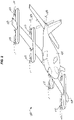
- FIG. 1 is a perspective view of an aircraft 100 in an illustrative embodiment.
- Aircraft 100 may be a manned aircraft that is flown by one or more pilots, or may be an unmanned aircraft (e.g., a drone).
- the structure of aircraft 100 is merely provided as an example, and the concepts described herein apply to any aircraft.
- aircraft 100 includes a fuselage 102, and wings 104-105 extending from opposite sides of fuselage 102 to define a support plane for horizontal or wing-borne flight.
- Aircraft 100 also includes a propeller 108 that provides thrust for wing-borne flight, although other types of engines are used to generate thrust in other embodiments.
- aircraft 100 includes one or more rotor assemblies 110.
- the number and locations of the rotor assemblies 110 shown in FIG. 1 are merely for example, and vary as desired. Further, although rotor assemblies 110 are illustrated as including two blades each, rotor assemblies 110 include a different number of blades greater than two in other embodiments.
- FIG. 2 is a perspective view of aircraft 100 during a cruise phase in an illustrative embodiment.
- the blades of rotor assemblies 110 passively orient themselves to reduce drag.
- rotor assemblies 110 are enhanced in that one or more blades include a blade alignment device 308 that passively orients the rotor assemblies 110 in response to an airflow around blade alignment device 308 when rotor assemblies 110 are free-wheeling (e.g., when rotor assemblies 110 are not driven in rotation). Since rotor assemblies 110 are oriented passively, the efficiency during the cruise phase illustrated in FIG. 2 is improved. Additionally, by passively aligning the propellers of rotor assemblies 110 with the local direction of the airflow, rotor assemblies 110 are positioned in the lowest possible drag position.
- blade alignment device 308 illustrated in FIG. 2 is depicted to have a particular shape, other embodiments exist for blade alignment device 308.
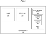
- FIG. 3 is a block diagram of rotor assembly 110 in an illustrative embodiment.
- rotor assembly 110 includes a rotary hub 302 that rotates about an axis (not shown).
- Rotor assembly 110 further includes a plurality of blades 304-305 that extend radially from rotary hub 302. Although only two of blades 304-305 are illustrated in FIG. 3 , rotor assembly 110 includes any number of blades greater than one as a matter of design choice.
- blade 304 includes surfaces 306-307, which form an airfoil for blade 304.
- Blade 304 includes a blade alignment device 308 that conforms to surface 306 and/or surface 307 of blade 304 in a stowed position, and projects away from surface 306 and/or surface 307 of blade 304 in a deployed position.
- blade alignment device 308 in the deployed position aligns blade 304 in response to an airflow around blade alignment device 308 when rotor assembly 110 is free-wheeling (e.g., when rotary hub 302 is not driven in rotation).
- Blade alignment device 308 is in the stowed position when rotor assembly 110 is in operation (e.g., when rotary hub 302 is driven in rotation) to ensure that blade alignment device 308 does not interfere with the chordwise airflow across surface 306 and/or surface 307 of blade 304, which would reduce the lift of blade 304.
- blade alignment device 308 is illustrated on blade 304 in this embodiment, blade alignment device 308 in other embodiments is implemented on any number of blades as a matter of design choice.
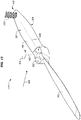
- FIG. 4A is a perspective view of a rotor assembly with a blade alignment device 308 proximate to a tip 410 of blade 304 and in a deployed position in an illustrative embodiment.
- rotor assembly 110 includes rotary hub 302, which is mechanically driven to rotate about an axis 402 in the direction of arrow 404 to provide lift to aircraft 100.
- Blades 304-305 extend radially from rotary hub 302 in this embodiment.
- blades 304-305 extend radially from rotary hub 302 along a longitudinal direction 406 that is substantially perpendicular to axis 402.
- Rotor assembly 110 in this embodiment further includes a spanwise fin 308-1, which operates similar to blade alignment device 308 previously described to passively orient rotor assembly 110 as illustrated in FIG. 2 .
- spanwise fin 308-1 (i.e., one embodiment of blade alignment device 308) is proximate to a tip 410 of blade 304 and projects away from surface 306 of blade 304 in the deployed position when rotor assembly 110 is free-wheeling.
- Spanwise fin 308-1 conforms to surface 306 of blade 304 in the stowed position when rotor assembly 110 is driven in rotation.
- spanwise fin 308-1 is placed along the span of the airfoil of blade 304.
- spanwise fin 308-1 is illustrated as projecting away from surface 306, spanwise fin 308-1 in other embodiments is implemented, instead of or in addition to, to project away from surface 307.
- FIG. 4B is a perspective view of rotor assembly 110 with blade alignment device 308 proximate to tip 410 of blade 304 and in a stowed position in an illustrative embodiment.
- spanwise fin 308-1 is in the stowed position when rotary hub 302 is mechanically driven to provide lift to aircraft 100.
- spanwise fin 308-1 is retained within a cutout 408 within blade 304, which allows spanwise fin 308-1 to conform to surface 306 and surface 307 of blade 304 when rotary hub 302 is mechanically driven in rotation.
- cutout 408 is illustrated near tip 410 of blade 304, cutout 408 in other embodiments is located at other positions between tip 410 and rotary hub 302 on blade 304 as a matter of design choice.
- spanwise fin 308-1 projects away from surface 306 of blade 304 (see FIG. 4A ) utilizing a spring (not shown) or other mechanical actuator (not shown) when rotor assembly 110 is idle.
- spanwise fin 308-1 is rotationally coupled to short edge 412 of cutout 408, and pivots about a pivot axis 409 out of cutout 408 in response to a trigger.
- the trigger in some embodiments, is the result of the release of a retaining device (not shown) or other mechanical feature which normally retains spanwise fin 308-1 within cutout 408 until activated.
- spanwise fin 308-1 conforms to and projects away from surface 306 of blade 304 in response to changes in a rotational rate of rotary hub 302.
- spanwise fin 308-1 passively transitions to the stowed position and conforms to surface 306 (e.g., spanwise fin 308-1 pivots at short edge 412 into cutout 408) in response to a rate of rotation being greater than a first rotational rate, and passively transitions to the deployed position and projects from surface 306 (e.g., spanwise fin 308-1 pivots at short edge 412 out of cutout 408) in response to the rate of rotation being less than a second rotational rate.
- the first rotational rate is greater than the second rotational rate.
- Spanwise fin 308-1 passively transitions to the stowed position and conforms to surface 306 of blade 304, and passively transition to the deployed position and projects away from surface 306 of blade 304 in response to changes in a centrifugal force applied to spanwise fin 308-1.
- Spanwise fin 308-1 passively transitions to the stowed position and conforms to surface 306 (e.g., spanwise fin 308-1 pivots at short edge 412 into cutout 408) in response to a centrifugal force applied to spanwise fin 308-1 being greater than a first centrifugal force value, and passively transitions to the deployed position and projects from surface 306 (e.g., spanwise fin 308-1 pivots at short edge 412 out of cutout 408) in response to the centrifugal force applied to spanwise fin 308-1 being less than a second centrifugal force value.
- the first centrifugal force value is greater than the second centrifugal force value.
- FIG. 5A is a perspective view of a rotor assembly with blade alignment device 308-1 proximate to a midpoint in blade 304 and in a deployed position in an illustrative embodiment
- FIG. 5B is a perspective view of the rotor assembly of FIG. 5B with blade alignment device 308-1 proximate to midpoint in blade 304 and in a stowed position in an illustrative embodiment.
- spanwise fine 308-1 may be located at any position between tip 410 of blade 304 and rotary hub 302.
- cutout 408 is proximate to a midpoint of blade 304 between tip 410 and rotary hub 302. This is desirable in some embodiments as a thickness of blade 304 typically increases from tip 410 and rotary hub 302.
- FIGS. 6-9 are top perspective views of rotor assembly 110 in illustrative embodiments.
- FIGS. 6-9 illustrate how spanwise fin 308-1 aligns blade 304 when aircraft 100 is in forward flight and rotor assembly 110 is free-wheeling (e.g., rotary hub 302 is free to rotate about axis 402 and is not driven in rotation).
- FIGS. 6-9 will be discussed with respect to spanwise fin 308-1, the principles illustrated in FIGS. 6-10 apply to other embodiments of blade alignment device 308, some of which will be discussed later.
- FIG. 6 illustrates the case whereby longitudinal direction 406 of rotor assembly 110 is oriented substantially perpendicular to an airflow 602.
- This orientation may generate the most drag upon aircraft 100, and may represent the natural orientation of rotor assembly 110 prior to spanwise fin 308-1 aligning blade 304.
- a torque 604 is generated upon rotary hub 302 which operates to rotate rotary hub 302 in a counter-clockwise direction.
- FIGS. 7-9 The process is illustrated in FIGS. 7-9 .
- As rotor assembly 110 rotates airflow 602 across spanwise fin 308-1 orients blade 304 in a downstream position with respect to airflow 602, and orients blade 305 in an upstream position with respect to airflow 602.
- the result of the orientation illustrated in FIG. 9 is that less drag on aircraft 100 is created as compared to the orientation illustrated in FIG. 6 .
- FIG. 10-12 are perspective views of rotor assembly 110 that utilizes a spanwise fin 308-2 as blade alignment device 308 in an illustrative embodiment not covered by the claimed subject matter.
- spanwise fin 308-2 is pivotably coupled to surface 306 of blade 304 along longitudinal direction 406. This is further illustrated in FIG. 11 , which illustrates a perspective view of rotor assembly 110 of surface 306.
- spanwise fin 308-2 projects away from surface 306 of blade 304 in the stowed position when rotor assembly 110 is idle or free-wheeling.
- FIG. 12 illustrates spanwise fin 308-2 in the deployed position when rotor assembly 110 is in operation (e.g., rotor assembly 110 is mechanically driven in rotation). In the deployed position, spanwise fin 308-2 pivots at surface 306 along an edge that is substantially parallel with longitudinal direction 406, which allows spanwise fin 308-2 to lay flat with respect to surface 306.
- spanwise fin 308-2 is illustrated near tip 410 of blade 304, spanwise fin 308-2 in other embodiments is located at other positions along blade 304 as a matter of design choice.
- spanwise fin 308-2 projects from surface 306 of blade 304 (see FIGS. 10-11 ) utilizing a spring (not shown) or other mechanical actuator (not shown) when rotor assembly 110 is not driven in rotation.
- spanwise fin 308-2 is held within a surface relief of surface 306 (not shown), and pivots out of the surface relief in response to a trigger.
- the trigger in some embodiments, is the result of the release of a retaining device (not shown) or other mechanical feature which normally retains spanwise fin 308-2 proximate to surface 306 until activated.
- spanwise fin 308-2 conforms to and projects away from surface 306 of blade 304 in response to changes in a rotational rate of rotor assembly 110.
- spanwise fin 308-2 passively transitions to the stowed position and conform to surface 306 (see FIG. 12 ) in response to a rate of rotation being greater than a first rotational rate, and passively transitions to the deployed position and project from surface 306 (see FIG. 11 ) in response to the rate of rotation being less than a second rotational rate.
- the first rotational rate is greater than the second rotational rate.
- spanwise fin 308-2 passively transitions to the stowed position and conforms, and passively transitions to the deployed position and project away from surface 306 of blade 304 in response to changes in a chordwise airflow 1102 applied to spanwise fin 308-2.
- Chordwise airflow 1102 is a flow of air directed across blade 304 from a leading edge 1104 to a trailing edge 1106 of blade 304 that is generated as rotor assembly 110 rotates.
- spanwise fin 308-2 passively transitions to the stowed position and conforms to surface 306 in response to chordwise airflow 1102 for blade 304 being greater than a first airflow (see FIG.
- chordwise airflow 1102 being less than a second airflow rate (see FIG. 11 ).
- the first airflow rate is greater than the second airflow rate.
- FIG. 13-14 is a perspective view of rotor assembly 110 that utilizes a grid fin 1302 as blade alignment device 308 in another illustrative embodiment.
- a grid fin 1302 projects away from surface 307 of blade 304 when in the deployed position, where a chordwise orientation of grid fin 1302 is substantially parallel to longitudinal direction 406.
- grid fins are a lattice of smaller aerodynamic surfaces arranged within a box, where a chord of the aerodynamic surfaces is short with respect to the other dimensions.
- grid fin 1302 projects away from surface 307 of blade 304.
- grid fin 1302 projects away from surface 306 of blade 304.
- grid fin 1302 is positioned at any location between rotary hub 302 and tip 410 of blade 304.
- FIG. 14 is a perspective view of rotor assembly 110 in another illustrative embodiment.
- grid fin 1302 conforms to surface 307 of blade 304 when in the stowed position.
- FIG. 15 is a perspective view of grid fin 1302 in an illustrative embodiment.
- grid fin 1302 includes a plurality of fins 1502 configured in a lattice, which are included within a box 1506. Fins 1502 include a leading edge 1508 and a trailing edge 1510 that define a chord 1512 of grid fin 1302. As previously described, chord 1512 of grid fin 1302 is generally shorter than a height 1514 of grid fin 1302 or a width 1516 of grid fin 1302. As previously described with respect to blade alignment device 308, grid fin 1302 aligns blade 304 in a similar manner in the presence of airflow 602 generated when aircraft 100 is in forward flight.
- FIG. 16 is a flow chart of a method 1600 of operating a rotor assembly for aircraft
- FIGS. 17-20 are flow charts depicting additional details of method 1600 in various illustrative embodiments.
- the steps of method 1600 will be discussed with respect to rotor assembly 110, although method 1600 may apply to other rotor assemblies, not shows.
- the steps of method 1600 are not all inclusive, and may include other steps, not shown. Further, the steps may be performed in an alternate order.
- Step 1602 of FIG. 16 comprises operating rotor assembly 110 in a free-wheeling state. This may occur, for example, when aircraft 100 is in forward flight and rotor assembly 110 is not driven in rotation.
- Step 1604 comprises aligning a blade that includes blade alignment device 308 (e.g., blade 304) in response to an airflow around blade alignment device 308.
- blade alignment device 308 e.g., blade 304
- longitudinal direction 406 of rotor assembly 110 is aligned in the direction of airflow 602 to maximize a reduction in drag.
- blade 304 of rotor assembly 110 is oriented in a downstream position in airflow 602 and blade 305 of rotor assembly 110 are oriented in an upstream position in airflow 602.
- Step 1702 of FIG. 17 comprises operating blade alignment device 308 in the deployed position (e.g., blade alignment device 308 projects away from surface 306 of blade 304) when rotor assembly 110 is free-wheeling.
- Step 1704 comprises operating blade alignment device 308 in the stowed position (e.g., blade alignment device 308 conforms to surface 306 of blade 304 during a portion of a span) when rotor assembly 110 is driven in rotation.
- rotary hub 302 is driven in rotation by a mechanical power source to provide lift to aircraft 100.
- blade alignment device 308 operates in the stowed position and conforms to surface 306 of blade 304.
- blade alignment device 308 passively transitions between the stowed position and the deployed position based on conditions acting on rotor assembly 110. In one embodiment, blade alignment device 308 passively transitions to the stowed position when a rate of rotation of rotary hub 302 is greater than a first rotational rate (see FIG. 18 , step 1802), and passively transitions to the deployed position when a rate of rotation of rotary hub 302 is less than a second rotational rate (see FIG. 18 , step 1804).
- blade alignment device 308 passively transitions to the stowed position in response to a chordwise airflow 1102 for blade 304 being greater than a first airflow rate (see FIG. 19 , step 1902), and passively transitions to the deployed position in response to chordwise airflow 1102 for blade 304 being less than a second airflow rate (see FIG. 19 , step 1904).
- Blade alignment device 308 passively transitions to the stowed position in response to a centrifugal force imposed on blade alignment device 308 being greater than a first centrifugal force value (see FIG. 20 , step 2002), and passively transitions to the deployed position in response to the centrifugal force imposed on blade alignment device 308 being less than a second centrifugal force (see FIG. 20 , step 2004).
- blade alignment device 308 for rotor assemblies 110 allows for the passive orientation of rotor assemblies 110 during the cruise phase of flight for aircraft 100, thereby reducing the drag imposed upon aircraft 100 for rotor assemblies 110 that are free-wheeling. Because blade alignment device 308 passively orients rotor assembly 110 during the cruise phase, mechanical power and/or complicated positioning sensors are not needed, which reduces the complexity of aircraft 100.
Landscapes
- Engineering & Computer Science (AREA)
- Aviation & Aerospace Engineering (AREA)
- Mechanical Engineering (AREA)
- Physics & Mathematics (AREA)
- Fluid Mechanics (AREA)
- Structures Of Non-Positive Displacement Pumps (AREA)
Description
- This disclosure relates to the field of aircraft and, in particular, to aircraft that utilize rotors.
- A type of aircraft that can take off, hover, and land vertically is referred to as a Vertical Take-Off and Landing (VTOL) aircraft. A VTOL aircraft has one or more rotors that produce vertical lift. Some VTOL aircraft also have fixed-wings that generate lift when the aircraft is propelled forward by a propeller, a jet engine, etc. When these fixed-wing aircraft convert from vertical flight to horizontal or wing-borne flight, the rotors are not driven in rotation. One problem is that the rotors can produce drag when they free-wheel, which hinders the efficiency of wing-borne flight.
- Document
US 9,409,642 B1 - Rotor assemblies for aircraft are described where one or more blades of the rotor assembly includes a blade alignment device that passively orients a blade in response to an airflow around the blade alignment device when the rotor assembly is free-wheeling.
- One embodiment comprises a method of operating a rotor assembly for aircraft. The method comprises operating the rotor assembly in a free-wheeling state, where the rotor assembly includes a rotary hub that rotates about an axis and a plurality of blades extending radially from the rotary hub. At least one of the plurality of blades includes a blade alignment device. The method further comprises aligning the at least one of the plurality of blades in response to airflow around the blade alignment device when the rotor assembly is in the free-wheeling state. The method further comprises operating the blade alignment device in a stowed position by conforming the blade alignment device to a surface of the at least one of the plurality of blades along at least a portion of a span when the rotor assembly is driven in rotation. Aligning the at least one of the plurality of blades further comprises operating the blade alignment device in a deployed position by projecting the blade alignment device away from a surface of the at least one of the plurality of blades when the rotor assembly is in the free-wheeling state. Operating the blade alignment device in the stowed position comprises passively transitioning the blade alignment device to the stowed position when a centrifugal force imposed on the blade alignment device is greater than a first centrifugal force value. Operating the blade alignment device in the deployed position comprises passively transitioning the blade alignment device to the deployed position when the centrifugal force imposed on the blade alignment device is less than a second centrifugal force value.
- Another embodiment comprises a rotor assembly for aircraft. The rotor assembly includes a rotary hub that rotates about an axis, and a plurality of blades extending radially from the rotary hub. At least one of the plurality of blades includes a blade alignment device that aligns the at least one of the plurality of blades in response to an airflow around the blade alignment device when the rotor assembly is free-wheeling. The blade alignment device is configured to conform to a surface of the at least one of the plurality of blades in a stowed position along at least a portion of a span when the rotor assembly is driven in rotation, and to project away from the surface of the at least one of the plurality of blades in a deployed position when the rotor assembly is free-wheeling. The blade alignment device is configured to passively transition to the stowed position when a centrifugal force imposed on the blade alignment device is greater than a first centrifugal force value, and to passively transition to the deployed position when the centrifugal force imposed on the blade alignment device is less than a second centrifugal force value.
- The features, functions, and advantages that have been discussed can be achieved independently in various embodiments or may be combined in yet other embodiments, further details of which can be seen with reference to the following description and drawings.
- Some embodiments are now described, by way of example only, and with reference to the accompanying drawings. The same reference number represents the same element or the same type of element on all drawings.
-
FIG. 1 is a perspective view of an aircraft in an illustrative embodiment. -
FIG. 2 is a perspective view of the aircraft ofFIG. 1 during a cruise phase in an illustrative embodiment. -
FIG. 3 is a block diagram of a rotor assembly in an illustrative embodiment. -
FIG. 4A is a perspective view of a rotor assembly with a blade alignment device proximate to a blade tip and in a deployed position in an illustrative embodiment. -
FIG. 4B is a perspective view of the rotor assembly ofFIG. 4A with the blade alignment device proximate to the blade tip and in a stowed position in an illustrative embodiment. -
FIG. 5A is a perspective view of a rotor assembly with a blade alignment device proximate to a midpoint in the blade and in a deployed position in an illustrative embodiment. -
FIG. 5B is a perspective view of the rotor assembly ofFIG. 5A with the blade alignment device proximate to a midpoint in the blade and in a stowed position in an illustrative embodiment. -
FIGS. 6-9 are top perspective views of the rotor assembly ofFIGS. 4A-4B in illustrative embodiments. -
FIGS. 10-12 are perspective views of a rotor assembly that utilizes a spanwise fin as a blade alignment device in an illustrative embodiment not covered by the claimed subject matter. -
FIGS. 13-14 are perspective views of a rotor assembly that utilizes a grid fin as a blade alignment device in an illustrative embodiment. -
FIG. 15 is a perspective view of the grid fin ofFIGS. 13-14 in an illustrative embodiment. -
FIG. 16 is a flow chart of a method of re-positioning a rotor assembly when the rotor assembly is free-wheeling in an illustrative embodiment. -
FIGS. 17-20 are flow charts depicting additional details of the method ofFIG. 16 in illustrative embodiments not all covered by the claimed subject matter. - The figures and the following description illustrate specific exemplary embodiments. It will be appreciated that those skilled in the art will be able to devise various arrangements that, although not explicitly described or shown herein, embody the principles described herein and are included within the scope of the claims that follow this description. Furthermore, any examples described herein are intended to aid in understanding the principles of the disclosure are to be construed as being without limitation. As a result, this disclosure is not limited to the specific embodiments or examples described below, but by the claims.
-
FIG. 1 is a perspective view of anaircraft 100 in an illustrative embodiment.Aircraft 100 may be a manned aircraft that is flown by one or more pilots, or may be an unmanned aircraft (e.g., a drone). The structure ofaircraft 100 is merely provided as an example, and the concepts described herein apply to any aircraft. In this example,aircraft 100 includes afuselage 102, and wings 104-105 extending from opposite sides offuselage 102 to define a support plane for horizontal or wing-borne flight.Aircraft 100 also includes apropeller 108 that provides thrust for wing-borne flight, although other types of engines are used to generate thrust in other embodiments. - To provide vertical flight (i.e., take-off, hover, and landing),
aircraft 100 includes one ormore rotor assemblies 110. The number and locations of therotor assemblies 110 shown inFIG. 1 are merely for example, and vary as desired. Further, althoughrotor assemblies 110 are illustrated as including two blades each,rotor assemblies 110 include a different number of blades greater than two in other embodiments. - As rotor assemblies 110 spin via a motor that can be operated mechanically, electrically, or using a combination of mechanically and electrically,
rotor assemblies 110 provide vertical lift so thataircraft 100 is able to take-off, hover, and land.FIG. 2 is a perspective view ofaircraft 100 during a cruise phase in an illustrative embodiment. InFIG. 2 , whenaircraft 100 transitions from vertical flight to wing-borne flight, the blades ofrotor assemblies 110 passively orient themselves to reduce drag. In the embodiments described herein,rotor assemblies 110 are enhanced in that one or more blades include ablade alignment device 308 that passively orients therotor assemblies 110 in response to an airflow aroundblade alignment device 308 whenrotor assemblies 110 are free-wheeling (e.g., whenrotor assemblies 110 are not driven in rotation). Sincerotor assemblies 110 are oriented passively, the efficiency during the cruise phase illustrated inFIG. 2 is improved. Additionally, by passively aligning the propellers ofrotor assemblies 110 with the local direction of the airflow,rotor assemblies 110 are positioned in the lowest possible drag position. If the propellers were mechanically locked into a fore-aft position, variations in the airflow around each propeller could cause them to not always be positioned precisely into the airflow. By allowing them to freely and passively find the direction of the airflow, drag is minimized. Althoughblade alignment device 308 illustrated inFIG. 2 is depicted to have a particular shape, other embodiments exist forblade alignment device 308. -
FIG. 3 is a block diagram ofrotor assembly 110 in an illustrative embodiment. In this embodiment,rotor assembly 110 includes arotary hub 302 that rotates about an axis (not shown).Rotor assembly 110 further includes a plurality of blades 304-305 that extend radially fromrotary hub 302. Although only two of blades 304-305 are illustrated inFIG. 3 ,rotor assembly 110 includes any number of blades greater than one as a matter of design choice. - In this embodiment,
blade 304 includes surfaces 306-307, which form an airfoil forblade 304.Blade 304 includes ablade alignment device 308 that conforms to surface 306 and/orsurface 307 ofblade 304 in a stowed position, and projects away fromsurface 306 and/orsurface 307 ofblade 304 in a deployed position. Generally,blade alignment device 308 in the deployed position alignsblade 304 in response to an airflow aroundblade alignment device 308 whenrotor assembly 110 is free-wheeling (e.g., whenrotary hub 302 is not driven in rotation).Blade alignment device 308 is in the stowed position whenrotor assembly 110 is in operation (e.g., whenrotary hub 302 is driven in rotation) to ensure thatblade alignment device 308 does not interfere with the chordwise airflow acrosssurface 306 and/orsurface 307 ofblade 304, which would reduce the lift ofblade 304. Althoughblade alignment device 308 is illustrated onblade 304 in this embodiment,blade alignment device 308 in other embodiments is implemented on any number of blades as a matter of design choice. -
FIG. 4A is a perspective view of a rotor assembly with ablade alignment device 308 proximate to atip 410 ofblade 304 and in a deployed position in an illustrative embodiment. In this embodiment,rotor assembly 110 includesrotary hub 302, which is mechanically driven to rotate about anaxis 402 in the direction ofarrow 404 to provide lift toaircraft 100. Blades 304-305 extend radially fromrotary hub 302 in this embodiment. In particular, blades 304-305 extend radially fromrotary hub 302 along alongitudinal direction 406 that is substantially perpendicular toaxis 402.Rotor assembly 110 in this embodiment further includes a spanwise fin 308-1, which operates similar toblade alignment device 308 previously described to passively orientrotor assembly 110 as illustrated inFIG. 2 . - In this embodiment, spanwise fin 308-1 (i.e., one embodiment of blade alignment device 308) is proximate to a
tip 410 ofblade 304 and projects away fromsurface 306 ofblade 304 in the deployed position whenrotor assembly 110 is free-wheeling. Spanwise fin 308-1conforms to surface 306 ofblade 304 in the stowed position whenrotor assembly 110 is driven in rotation. Generally, spanwise fin 308-1 is placed along the span of the airfoil ofblade 304. Although spanwise fin 308-1 is illustrated as projecting away fromsurface 306, spanwise fin 308-1 in other embodiments is implemented, instead of or in addition to, to project away fromsurface 307. -
FIG. 4B is a perspective view ofrotor assembly 110 withblade alignment device 308 proximate to tip 410 ofblade 304 and in a stowed position in an illustrative embodiment. InFIG. 4B , spanwise fin 308-1 is in the stowed position whenrotary hub 302 is mechanically driven to provide lift toaircraft 100. In the stowed position, spanwise fin 308-1 is retained within acutout 408 withinblade 304, which allows spanwise fin 308-1 to conform to surface 306 andsurface 307 ofblade 304 whenrotary hub 302 is mechanically driven in rotation. Althoughcutout 408 is illustrated neartip 410 ofblade 304,cutout 408 in other embodiments is located at other positions betweentip 410 androtary hub 302 onblade 304 as a matter of design choice. - In some embodiments, spanwise fin 308-1 projects away from
surface 306 of blade 304 (seeFIG. 4A ) utilizing a spring (not shown) or other mechanical actuator (not shown) whenrotor assembly 110 is idle. For instance, spanwise fin 308-1 is rotationally coupled toshort edge 412 ofcutout 408, and pivots about apivot axis 409 out ofcutout 408 in response to a trigger. The trigger, in some embodiments, is the result of the release of a retaining device (not shown) or other mechanical feature which normally retains spanwise fin 308-1 withincutout 408 until activated. - In some embodiments, spanwise fin 308-1 conforms to and projects away from
surface 306 ofblade 304 in response to changes in a rotational rate ofrotary hub 302. For example, spanwise fin 308-1 passively transitions to the stowed position and conforms to surface 306 (e.g., spanwise fin 308-1 pivots atshort edge 412 into cutout 408) in response to a rate of rotation being greater than a first rotational rate, and passively transitions to the deployed position and projects from surface 306 (e.g., spanwise fin 308-1 pivots atshort edge 412 out of cutout 408) in response to the rate of rotation being less than a second rotational rate. In some embodiments, the first rotational rate is greater than the second rotational rate. - Spanwise fin 308-1 passively transitions to the stowed position and conforms to surface 306 of
blade 304, and passively transition to the deployed position and projects away fromsurface 306 ofblade 304 in response to changes in a centrifugal force applied to spanwise fin 308-1. Spanwise fin 308-1 passively transitions to the stowed position and conforms to surface 306 (e.g., spanwise fin 308-1 pivots atshort edge 412 into cutout 408) in response to a centrifugal force applied to spanwise fin 308-1 being greater than a first centrifugal force value, and passively transitions to the deployed position and projects from surface 306 (e.g., spanwise fin 308-1 pivots atshort edge 412 out of cutout 408) in response to the centrifugal force applied to spanwise fin 308-1 being less than a second centrifugal force value. In these embodiments, the first centrifugal force value is greater than the second centrifugal force value. -
FIG. 5A is a perspective view of a rotor assembly with blade alignment device 308-1 proximate to a midpoint inblade 304 and in a deployed position in an illustrative embodiment, andFIG. 5B is a perspective view of the rotor assembly ofFIG. 5B with blade alignment device 308-1 proximate to midpoint inblade 304 and in a stowed position in an illustrative embodiment. - As discussed previously, spanwise fine 308-1 may be located at any position between
tip 410 ofblade 304 androtary hub 302. InFIGS. 5A-5B ,cutout 408 is proximate to a midpoint ofblade 304 betweentip 410 androtary hub 302. This is desirable in some embodiments as a thickness ofblade 304 typically increases fromtip 410 androtary hub 302. -
FIGS. 6-9 are top perspective views ofrotor assembly 110 in illustrative embodiments. In particular,FIGS. 6-9 illustrate how spanwise fin 308-1 alignsblade 304 whenaircraft 100 is in forward flight androtor assembly 110 is free-wheeling (e.g.,rotary hub 302 is free to rotate aboutaxis 402 and is not driven in rotation). AlthoughFIGS. 6-9 will be discussed with respect to spanwise fin 308-1, the principles illustrated inFIGS. 6-10 apply to other embodiments ofblade alignment device 308, some of which will be discussed later. -
FIG. 6 illustrates the case wherebylongitudinal direction 406 ofrotor assembly 110 is oriented substantially perpendicular to anairflow 602. This orientation may generate the most drag uponaircraft 100, and may represent the natural orientation ofrotor assembly 110 prior to spanwise fin 308-1 aligningblade 304. Asairflow 602 flows across spanwise fin 308-1, atorque 604 is generated uponrotary hub 302 which operates to rotaterotary hub 302 in a counter-clockwise direction. The process is illustrated inFIGS. 7-9 . Asrotor assembly 110 rotates,airflow 602 across spanwise fin 308-1orients blade 304 in a downstream position with respect toairflow 602, and orientsblade 305 in an upstream position with respect toairflow 602. The result of the orientation illustrated inFIG. 9 is that less drag onaircraft 100 is created as compared to the orientation illustrated inFIG. 6 . -
FIG. 10-12 are perspective views ofrotor assembly 110 that utilizes a spanwise fin 308-2 asblade alignment device 308 in an illustrative embodiment not covered by the claimed subject matter. In this embodiment not covered by the claimed subject matter, spanwise fin 308-2 is pivotably coupled to surface 306 ofblade 304 alonglongitudinal direction 406. This is further illustrated inFIG. 11 , which illustrates a perspective view ofrotor assembly 110 ofsurface 306. - In the embodiments illustrated in
FIGS. 10-11 which is not covered by the claimed subject matter, spanwise fin 308-2 projects away fromsurface 306 ofblade 304 in the stowed position whenrotor assembly 110 is idle or free-wheeling.FIG. 12 illustrates spanwise fin 308-2 in the deployed position whenrotor assembly 110 is in operation (e.g.,rotor assembly 110 is mechanically driven in rotation). In the deployed position, spanwise fin 308-2 pivots atsurface 306 along an edge that is substantially parallel withlongitudinal direction 406, which allows spanwise fin 308-2 to lay flat with respect tosurface 306. Although spanwise fin 308-2 is illustrated neartip 410 ofblade 304, spanwise fin 308-2 in other embodiments is located at other positions alongblade 304 as a matter of design choice. - In some embodiments not covered by the claimed subject matter, spanwise fin 308-2 projects from
surface 306 of blade 304 (seeFIGS. 10-11 ) utilizing a spring (not shown) or other mechanical actuator (not shown) whenrotor assembly 110 is not driven in rotation. For instance, spanwise fin 308-2 is held within a surface relief of surface 306 (not shown), and pivots out of the surface relief in response to a trigger. The trigger, in some embodiments, is the result of the release of a retaining device (not shown) or other mechanical feature which normally retains spanwise fin 308-2 proximate to surface 306 until activated. - In some embodiments not covered by the claimed subject matter, spanwise fin 308-2 conforms to and projects away from
surface 306 ofblade 304 in response to changes in a rotational rate ofrotor assembly 110. For example, spanwise fin 308-2 passively transitions to the stowed position and conform to surface 306 (seeFIG. 12 ) in response to a rate of rotation being greater than a first rotational rate, and passively transitions to the deployed position and project from surface 306 (seeFIG. 11 ) in response to the rate of rotation being less than a second rotational rate. In some embodiments, the first rotational rate is greater than the second rotational rate. - In other embodiments not covered by the claimed subject matter, spanwise fin 308-2 passively transitions to the stowed position and conforms, and passively transitions to the deployed position and project away from
surface 306 ofblade 304 in response to changes in achordwise airflow 1102 applied to spanwise fin 308-2.Chordwise airflow 1102 is a flow of air directed acrossblade 304 from aleading edge 1104 to atrailing edge 1106 ofblade 304 that is generated asrotor assembly 110 rotates. For example, spanwise fin 308-2 passively transitions to the stowed position and conforms to surface 306 in response tochordwise airflow 1102 forblade 304 being greater than a first airflow (seeFIG. 12 ), and passively transitions to the deployed position and projects away fromsurface 306 ofblade 304 in response tochordwise airflow 1102 being less than a second airflow rate (seeFIG. 11 ). In some embodiments, the first airflow rate is greater than the second airflow rate. -
FIG. 13-14 is a perspective view ofrotor assembly 110 that utilizes agrid fin 1302 asblade alignment device 308 in another illustrative embodiment. In this embodiment, agrid fin 1302 projects away fromsurface 307 ofblade 304 when in the deployed position, where a chordwise orientation ofgrid fin 1302 is substantially parallel tolongitudinal direction 406. Generally, grid fins are a lattice of smaller aerodynamic surfaces arranged within a box, where a chord of the aerodynamic surfaces is short with respect to the other dimensions. In the embodiment illustrated inFIG. 13 ,grid fin 1302 projects away fromsurface 307 ofblade 304. In other embodiments,grid fin 1302 projects away fromsurface 306 ofblade 304. In some embodiments,grid fin 1302 is positioned at any location betweenrotary hub 302 and tip 410 ofblade 304. -
FIG. 14 is a perspective view ofrotor assembly 110 in another illustrative embodiment. In this embodiment,grid fin 1302 conforms to surface 307 ofblade 304 when in the stowed position.FIG. 15 is a perspective view ofgrid fin 1302 in an illustrative embodiment. In this embodiment,grid fin 1302 includes a plurality offins 1502 configured in a lattice, which are included within abox 1506.Fins 1502 include aleading edge 1508 and atrailing edge 1510 that define achord 1512 ofgrid fin 1302. As previously described,chord 1512 ofgrid fin 1302 is generally shorter than aheight 1514 ofgrid fin 1302 or awidth 1516 ofgrid fin 1302. As previously described with respect toblade alignment device 308,grid fin 1302 alignsblade 304 in a similar manner in the presence ofairflow 602 generated whenaircraft 100 is in forward flight. -
FIG. 16 is a flow chart of amethod 1600 of operating a rotor assembly for aircraft, andFIGS. 17-20 are flow charts depicting additional details ofmethod 1600 in various illustrative embodiments. The steps ofmethod 1600 will be discussed with respect torotor assembly 110, althoughmethod 1600 may apply to other rotor assemblies, not shows. The steps ofmethod 1600 are not all inclusive, and may include other steps, not shown. Further, the steps may be performed in an alternate order. -
Step 1602 ofFIG. 16 comprises operatingrotor assembly 110 in a free-wheeling state. This may occur, for example, whenaircraft 100 is in forward flight androtor assembly 110 is not driven in rotation.Step 1604 comprises aligning a blade that includes blade alignment device 308 (e.g., blade 304) in response to an airflow aroundblade alignment device 308. For example,longitudinal direction 406 ofrotor assembly 110 is aligned in the direction ofairflow 602 to maximize a reduction in drag. In one embodiment,blade 304 ofrotor assembly 110 is oriented in a downstream position inairflow 602 andblade 305 ofrotor assembly 110 are oriented in an upstream position inairflow 602. -
Step 1702 ofFIG. 17 comprises operatingblade alignment device 308 in the deployed position (e.g.,blade alignment device 308 projects away fromsurface 306 of blade 304) whenrotor assembly 110 is free-wheeling.Step 1704 comprises operatingblade alignment device 308 in the stowed position (e.g.,blade alignment device 308 conforms to surface 306 ofblade 304 during a portion of a span) whenrotor assembly 110 is driven in rotation. For example, during take-off, hover, and landing foraircraft 100,rotary hub 302 is driven in rotation by a mechanical power source to provide lift toaircraft 100. During this phase of operation,blade alignment device 308 operates in the stowed position and conforms to surface 306 ofblade 304. - In some embodiments,
blade alignment device 308 passively transitions between the stowed position and the deployed position based on conditions acting onrotor assembly 110. In one embodiment,blade alignment device 308 passively transitions to the stowed position when a rate of rotation ofrotary hub 302 is greater than a first rotational rate (seeFIG. 18 , step 1802), and passively transitions to the deployed position when a rate of rotation ofrotary hub 302 is less than a second rotational rate (seeFIG. 18 , step 1804). - In another embodiment not according to the claimed invention,
blade alignment device 308 passively transitions to the stowed position in response to achordwise airflow 1102 forblade 304 being greater than a first airflow rate (seeFIG. 19 , step 1902), and passively transitions to the deployed position in response tochordwise airflow 1102 forblade 304 being less than a second airflow rate (seeFIG. 19 , step 1904). -
Blade alignment device 308 passively transitions to the stowed position in response to a centrifugal force imposed onblade alignment device 308 being greater than a first centrifugal force value (seeFIG. 20 , step 2002), and passively transitions to the deployed position in response to the centrifugal force imposed onblade alignment device 308 being less than a second centrifugal force (seeFIG. 20 , step 2004). - The use of
blade alignment device 308 forrotor assemblies 110 allows for the passive orientation ofrotor assemblies 110 during the cruise phase of flight foraircraft 100, thereby reducing the drag imposed uponaircraft 100 forrotor assemblies 110 that are free-wheeling. Becauseblade alignment device 308 passively orientsrotor assembly 110 during the cruise phase, mechanical power and/or complicated positioning sensors are not needed, which reduces the complexity ofaircraft 100. - Although specific embodiments were described herein, the scope is not limited to those specific embodiments. Rather, the scope is defined by the following claims.
Claims (15)
- A method (1600) of operating a rotor assembly (110) for aircraft (100), comprising:operating (1602) the rotor assembly (110) in a free-wheeling state, the rotor assembly (110) comprising a rotary hub (302) configured to rotate about an axis (402), a plurality of blades (304, 305) extending radially from the rotary hub (302), wherein at least one of the plurality of blades (304, 305) includes a blade alignment device (308);aligning (1604) the at least one of the plurality of blades (304, 305) in response to airflow (602) around the blade alignment device (308) when the rotor assembly (110) is in the free-wheeling state; andoperating the blade alignment device (308) in a stowed position by conforming the blade alignment device (308) to a surface (306, 307) of the at least one of the plurality of blades (304, 305) along at least a portion of a span when the rotor assembly (110) is driven in rotation,wherein aligning the at least one of the plurality of blades (304, 305) further comprises:operating the blade alignment device (308) in a deployed position by projecting the blade alignment device (308) away from a surface (306, 307) of the at least one of the plurality of blades (304, 305) when the rotor assembly (110) is in the free-wheeling state,wherein operating the blade alignment device (308) in the stowed position comprises:passively transitioning the blade alignment device (308) to the stowed position when a centrifugal force imposed on the blade alignment device (308) is greater than a first centrifugal force value, andwherein operating the blade alignment device (308) in the deployed position comprises:
passively transitioning the blade alignment device (308) to the deployed position when the centrifugal force imposed on the blade alignment device (308) is less than a second centrifugal force value. - The method of claim 1, wherein the first centrifugal force value is greater than the second centrifugal force value.
- The method of claim 1 or 2, wherein:operating the blade alignment device (308) in the stowed position comprises:
passively transitioning the blade alignment device (308) to the stowed position when a rate of rotation is greater than a first rotational rate, andoperating the blade alignment device (308) in the deployed position comprises:
passively transitioning the blade alignment device (308) to the deployed position when the rate of rotation is less than a second rotational rate. - The method according to any of claims 1 to 3, whereinthe at least one of the plurality of blades (304, 305) includes a cutout (408) disposed between a tip (410) of the at least one of the plurality of blades (304, 305) and the rotary hub (302), andthe blade alignment device (308) preferably comprises a spanwise fin (308-1) that is pivotably coupled to an edge of the cutout (408).
- The method according to any of claims 1 to 3, wherein
the blade alignment device (308) comprises a grid fin (1302) that is pivotably coupled to the surface (306, 307) of the at least one of the plurality of blades (304, 305), wherein a chord of the grid fin (1302) is substantially parallel to a longitudinal direction of the at least one of the plurality of blades (304, 305) when in the deployed position. - A rotor assembly (110) for aircraft (100), the rotor assembly (110) comprising:a rotary hub (302) configured to rotate about an axis (402); anda plurality of blades (304, 305) extending radially from the rotary hub (302),wherein at least one of the plurality of blades (304, 305) includes a blade alignment device (308), the blade alignment device (308) configured to align the at least one of the plurality of blades (304, 305) in response to airflow around the blade alignment device (308) when the rotor assembly (110) is free-wheeling,wherein the blade alignment device (308) is configured to conform to a surface (306, 307) of the at least one of the plurality of blades (304, 305) in a stowed position along at least a portion of a span when the rotor assembly (110) is driven in rotation, and to project away from the surface (306, 307) of the at least one of the plurality of blades (304, 305) in a deployed position when the rotor assembly (110) is free-wheeling,wherein the blade alignment device (308) is configured to passively transition to the stowed position when a centrifugal force imposed on the blade alignment device (308) is greater than a first centrifugal force value, and to passively transition to the deployed position when the centrifugal force imposed on the blade alignment device (308) is less than a second centrifugal force value.
- The rotor assembly (110) of claim 6, wherein the first centrifugal force value is greater than the second centrifugal force value.
- The rotor assembly of claim 6 or 7, wherein:
the blade alignment device (308) is configured to passively transition to the stowed position when a rate of rotation is greater than a first rotational rate, and to passively transition to the deployed position when the rate of rotation is less than a second rotational rate. - The rotor assembly of any of claims 6 to 8, wherein:the at least one of the plurality of blades (304, 305) includes a cutout (408) disposed between a tip (410) of the at least one of the plurality of blades (304, 305) and the rotary hub (302), andthe blade alignment device (308) preferably comprises a spanwise fin (308-1) that is pivotably coupled to an edge of the cutout (408).
- The rotor assembly of any of claims 6 to 8, wherein:
the blade alignment device (308) comprises a grid fin (1302) that is pivotably coupled to the surface (306, 307) of the at least one of the plurality of blades (304, 305), wherein a chord of the grid fin (1302) is substantially parallel to a longitudinal direction of the at least one of the plurality of blades (304, 305) when in the deployed position. - An aircraft (100), comprising:
one or more rotor assemblies (110) according to any of claims 6 to 10, each rotor assembly (110) being configured to provide lift for the aircraft (100). - The aircraft of claim 11, wherein, as the rotor assemblies (110) spin via a motor that can be operated mechanically, electrically, or using a combination of mechanically and electrically, the rotor assemblies (110) provide vertical lift so that the aircraft (100) is able to take-off, hover, and land.
- The aircraft of claim 11 or 12, wherein the aircraft (100) includes a fuselage (102), and wings (104-105) extending from opposite sides of fuselage (102) to define a support plane for horizontal or wing-borne flight.
- The aircraft of any of claims 11 to 13, wherein the aircraft (100) also includes a propeller (108) that provides thrust for wing-borne flight.
- The aircraft of any of claims 11 to 14, wherein, when the aircraft (100) transitions from vertical flight to wing-borne flight, the blades of the rotor assemblies (110) passively orient themselves to reduce drag.
Applications Claiming Priority (1)
| Application Number | Priority Date | Filing Date | Title |
|---|---|---|---|
| US16/515,340 US11305871B2 (en) | 2019-07-18 | 2019-07-18 | Passive rotor alignment in a free-wheeling state |
Publications (2)
| Publication Number | Publication Date |
|---|---|
| EP3766780A1 EP3766780A1 (en) | 2021-01-20 |
| EP3766780B1 true EP3766780B1 (en) | 2022-09-07 |
Family
ID=71409163
Family Applications (1)
| Application Number | Title | Priority Date | Filing Date |
|---|---|---|---|
| EP20183121.1A Active EP3766780B1 (en) | 2019-07-18 | 2020-06-30 | Passive rotor alignment in a free-wheeling state |
Country Status (3)
| Country | Link |
|---|---|
| US (1) | US11305871B2 (en) |
| EP (1) | EP3766780B1 (en) |
| CN (1) | CN112238936B (en) |
Families Citing this family (1)
| Publication number | Priority date | Publication date | Assignee | Title |
|---|---|---|---|---|
| US12199494B2 (en) * | 2022-12-02 | 2025-01-14 | The Boeing Company | Locking assembly for a propeller rotor of an aircraft, a rotor assembly for the aircraft, and a method |
Family Cites Families (10)
| Publication number | Priority date | Publication date | Assignee | Title |
|---|---|---|---|---|
| US7243879B2 (en) * | 2001-12-06 | 2007-07-17 | Kazak Composites, Incorporated | Lattice fin for missiles or other fluid-born bodies and method for producing same |
| US7475847B2 (en) * | 2002-09-09 | 2009-01-13 | Gerbino Allen J | Retractable lifting blades for aircraft |
| US8516899B2 (en) * | 2010-10-06 | 2013-08-27 | Siemens Energy, Inc. | System for remote monitoring of aerodynamic flow conditions |
| CN106573677B (en) * | 2014-03-18 | 2020-09-15 | 杰欧比飞行有限公司 | Aerodynamically efficient light vertical take-off and landing aircraft with pivoting rotors and retracting rotor blades |
| JP6632542B2 (en) * | 2014-03-18 | 2020-01-22 | ジョビー エイビエイション インクJoby Aviation, Inc. | Aerodynamically efficient lightweight vertical take-off and landing aircraft with swirling rotor blades and contained rotor blades |
| US10046855B2 (en) * | 2014-03-18 | 2018-08-14 | Joby Aero, Inc. | Impact resistant propeller system, fast response electric propulsion system and lightweight vertical take-off and landing aircraft using same |
| US10137982B1 (en) | 2014-05-11 | 2018-11-27 | Wing Aviation Llc | Propeller units |
| US9334049B1 (en) | 2014-12-03 | 2016-05-10 | Amazon Technologies, Inc. | Single blade rotor system for use in a vertical takeoff and landing (VTOL) aircraft |
| US9409642B1 (en) * | 2015-06-24 | 2016-08-09 | Amazon Technologies, Inc. | Collapsible lift propellers |
| GB2550916B (en) | 2016-05-30 | 2018-09-26 | Kapeter Luka | Propeller-hub assembly with folding blades for VTOL aircraft |
-
2019
- 2019-07-18 US US16/515,340 patent/US11305871B2/en active Active
-
2020
- 2020-06-30 EP EP20183121.1A patent/EP3766780B1/en active Active
- 2020-07-13 CN CN202010667697.3A patent/CN112238936B/en active Active
Also Published As
| Publication number | Publication date |
|---|---|
| EP3766780A1 (en) | 2021-01-20 |
| CN112238936A (en) | 2021-01-19 |
| US20210016876A1 (en) | 2021-01-21 |
| CN112238936B (en) | 2025-12-12 |
| US11305871B2 (en) | 2022-04-19 |
Similar Documents
| Publication | Publication Date | Title |
|---|---|---|
| JP6949869B2 (en) | Tail sitter aircraft rotor assembly | |
| US8376264B1 (en) | Rotor for a dual mode aircraft | |
| US10633092B2 (en) | UAV with wing-plate assemblies providing efficient vertical takeoff and landing capability | |
| US20210206487A1 (en) | Aircraft and Modular Propulsion Unit | |
| EP3529150B1 (en) | Ventilated rotor mounting boom for personal aircraft | |
| US11254425B2 (en) | Differential blade geometry for rotor assemblies | |
| US20100327123A1 (en) | Rotorcraft with Variable Incident Wing | |
| US11242141B2 (en) | Method of drag reduction on vehicle with internal rotors | |
| US10464667B2 (en) | Oblique rotor-wing aircraft | |
| US11267564B2 (en) | Aircraft with rotating ducted fan | |
| KR101953892B1 (en) | Vertical takeoff and landing aircraft with distributed propulsion system and control method of thereof | |
| US12037110B2 (en) | Rotary wing aircraft with a shrouded tail propeller | |
| US20180057160A1 (en) | Aircraft Generating a Triaxial Dynamic Thrust Matrix | |
| US11046421B2 (en) | Slotted flaperon seal mechanism for aircraft devices | |
| CN115103800A (en) | Vertically landing reversing aircraft and associated folding method | |
| US11305871B2 (en) | Passive rotor alignment in a free-wheeling state | |
| US12084183B2 (en) | Rotary wing aircraft with an asymmetrical front section | |
| US12545400B2 (en) | Parallel and series multi-stage electric fan | |
| US10589842B2 (en) | Spinners for use on tiltrotor aircraft | |
| CN117864384A (en) | Aircraft, control system for aircraft, and method for controlling aircraft | |
| US12486026B1 (en) | Aerodynamic rotor blade strake | |
| US12534192B2 (en) | Body with rotating object moving through fluid | |
| US12570398B2 (en) | Multiple flight mode aircraft architectures and controls | |
| US20230202688A1 (en) | Vertical takeoff and landing (vtol) aircraft system and method | |
| US20260138740A1 (en) | Parallel and Series Multi-Stage Electric Fan |
Legal Events
| Date | Code | Title | Description |
|---|---|---|---|
| PUAI | Public reference made under article 153(3) epc to a published international application that has entered the european phase |
Free format text: ORIGINAL CODE: 0009012 |
|
| STAA | Information on the status of an ep patent application or granted ep patent |
Free format text: STATUS: THE APPLICATION HAS BEEN PUBLISHED |
|
| AK | Designated contracting states |
Kind code of ref document: A1 Designated state(s): AL AT BE BG CH CY CZ DE DK EE ES FI FR GB GR HR HU IE IS IT LI LT LU LV MC MK MT NL NO PL PT RO RS SE SI SK SM TR |
|
| AX | Request for extension of the european patent |
Extension state: BA ME |
|
| STAA | Information on the status of an ep patent application or granted ep patent |
Free format text: STATUS: REQUEST FOR EXAMINATION WAS MADE |
|
| 17P | Request for examination filed |
Effective date: 20210618 |
|
| RBV | Designated contracting states (corrected) |
Designated state(s): AL AT BE BG CH CY CZ DE DK EE ES FI FR GB GR HR HU IE IS IT LI LT LU LV MC MK MT NL NO PL PT RO RS SE SI SK SM TR |
|
| GRAP | Despatch of communication of intention to grant a patent |
Free format text: ORIGINAL CODE: EPIDOSNIGR1 |
|
| STAA | Information on the status of an ep patent application or granted ep patent |
Free format text: STATUS: GRANT OF PATENT IS INTENDED |
|
| INTG | Intention to grant announced |
Effective date: 20220405 |
|
| GRAS | Grant fee paid |
Free format text: ORIGINAL CODE: EPIDOSNIGR3 |
|
| GRAA | (expected) grant |
Free format text: ORIGINAL CODE: 0009210 |
|
| STAA | Information on the status of an ep patent application or granted ep patent |
Free format text: STATUS: THE PATENT HAS BEEN GRANTED |
|
| AK | Designated contracting states |
Kind code of ref document: B1 Designated state(s): AL AT BE BG CH CY CZ DE DK EE ES FI FR GB GR HR HU IE IS IT LI LT LU LV MC MK MT NL NO PL PT RO RS SE SI SK SM TR |
|
| REG | Reference to a national code |
Ref country code: GB Ref legal event code: FG4D |
|
| REG | Reference to a national code |
Ref country code: CH Ref legal event code: EP Ref country code: AT Ref legal event code: REF Ref document number: 1516859 Country of ref document: AT Kind code of ref document: T Effective date: 20220915 |
|
| REG | Reference to a national code |
Ref country code: IE Ref legal event code: FG4D |
|
| REG | Reference to a national code |
Ref country code: DE Ref legal event code: R096 Ref document number: 602020004920 Country of ref document: DE |
|
| REG | Reference to a national code |
Ref country code: LT Ref legal event code: MG9D |
|
| REG | Reference to a national code |
Ref country code: NL Ref legal event code: MP Effective date: 20220907 |
|
| PG25 | Lapsed in a contracting state [announced via postgrant information from national office to epo] |
Ref country code: SE Free format text: LAPSE BECAUSE OF FAILURE TO SUBMIT A TRANSLATION OF THE DESCRIPTION OR TO PAY THE FEE WITHIN THE PRESCRIBED TIME-LIMIT Effective date: 20220907 Ref country code: RS Free format text: LAPSE BECAUSE OF FAILURE TO SUBMIT A TRANSLATION OF THE DESCRIPTION OR TO PAY THE FEE WITHIN THE PRESCRIBED TIME-LIMIT Effective date: 20220907 Ref country code: NO Free format text: LAPSE BECAUSE OF FAILURE TO SUBMIT A TRANSLATION OF THE DESCRIPTION OR TO PAY THE FEE WITHIN THE PRESCRIBED TIME-LIMIT Effective date: 20221207 Ref country code: LV Free format text: LAPSE BECAUSE OF FAILURE TO SUBMIT A TRANSLATION OF THE DESCRIPTION OR TO PAY THE FEE WITHIN THE PRESCRIBED TIME-LIMIT Effective date: 20220907 Ref country code: LT Free format text: LAPSE BECAUSE OF FAILURE TO SUBMIT A TRANSLATION OF THE DESCRIPTION OR TO PAY THE FEE WITHIN THE PRESCRIBED TIME-LIMIT Effective date: 20220907 Ref country code: FI Free format text: LAPSE BECAUSE OF FAILURE TO SUBMIT A TRANSLATION OF THE DESCRIPTION OR TO PAY THE FEE WITHIN THE PRESCRIBED TIME-LIMIT Effective date: 20220907 |
|
| REG | Reference to a national code |
Ref country code: AT Ref legal event code: MK05 Ref document number: 1516859 Country of ref document: AT Kind code of ref document: T Effective date: 20220907 |
|
| PG25 | Lapsed in a contracting state [announced via postgrant information from national office to epo] |
Ref country code: HR Free format text: LAPSE BECAUSE OF FAILURE TO SUBMIT A TRANSLATION OF THE DESCRIPTION OR TO PAY THE FEE WITHIN THE PRESCRIBED TIME-LIMIT Effective date: 20220907 Ref country code: GR Free format text: LAPSE BECAUSE OF FAILURE TO SUBMIT A TRANSLATION OF THE DESCRIPTION OR TO PAY THE FEE WITHIN THE PRESCRIBED TIME-LIMIT Effective date: 20221208 |
|
| PG25 | Lapsed in a contracting state [announced via postgrant information from national office to epo] |
Ref country code: SM Free format text: LAPSE BECAUSE OF FAILURE TO SUBMIT A TRANSLATION OF THE DESCRIPTION OR TO PAY THE FEE WITHIN THE PRESCRIBED TIME-LIMIT Effective date: 20220907 Ref country code: RO Free format text: LAPSE BECAUSE OF FAILURE TO SUBMIT A TRANSLATION OF THE DESCRIPTION OR TO PAY THE FEE WITHIN THE PRESCRIBED TIME-LIMIT Effective date: 20220907 Ref country code: PT Free format text: LAPSE BECAUSE OF FAILURE TO SUBMIT A TRANSLATION OF THE DESCRIPTION OR TO PAY THE FEE WITHIN THE PRESCRIBED TIME-LIMIT Effective date: 20230109 Ref country code: ES Free format text: LAPSE BECAUSE OF FAILURE TO SUBMIT A TRANSLATION OF THE DESCRIPTION OR TO PAY THE FEE WITHIN THE PRESCRIBED TIME-LIMIT Effective date: 20220907 Ref country code: CZ Free format text: LAPSE BECAUSE OF FAILURE TO SUBMIT A TRANSLATION OF THE DESCRIPTION OR TO PAY THE FEE WITHIN THE PRESCRIBED TIME-LIMIT Effective date: 20220907 Ref country code: AT Free format text: LAPSE BECAUSE OF FAILURE TO SUBMIT A TRANSLATION OF THE DESCRIPTION OR TO PAY THE FEE WITHIN THE PRESCRIBED TIME-LIMIT Effective date: 20220907 |
|
| PG25 | Lapsed in a contracting state [announced via postgrant information from national office to epo] |
Ref country code: SK Free format text: LAPSE BECAUSE OF FAILURE TO SUBMIT A TRANSLATION OF THE DESCRIPTION OR TO PAY THE FEE WITHIN THE PRESCRIBED TIME-LIMIT Effective date: 20220907 Ref country code: PL Free format text: LAPSE BECAUSE OF FAILURE TO SUBMIT A TRANSLATION OF THE DESCRIPTION OR TO PAY THE FEE WITHIN THE PRESCRIBED TIME-LIMIT Effective date: 20220907 Ref country code: IS Free format text: LAPSE BECAUSE OF FAILURE TO SUBMIT A TRANSLATION OF THE DESCRIPTION OR TO PAY THE FEE WITHIN THE PRESCRIBED TIME-LIMIT Effective date: 20230107 Ref country code: EE Free format text: LAPSE BECAUSE OF FAILURE TO SUBMIT A TRANSLATION OF THE DESCRIPTION OR TO PAY THE FEE WITHIN THE PRESCRIBED TIME-LIMIT Effective date: 20220907 |
|
| REG | Reference to a national code |
Ref country code: DE Ref legal event code: R097 Ref document number: 602020004920 Country of ref document: DE |
|
| P01 | Opt-out of the competence of the unified patent court (upc) registered |
Effective date: 20230516 |
|
| PG25 | Lapsed in a contracting state [announced via postgrant information from national office to epo] |
Ref country code: NL Free format text: LAPSE BECAUSE OF FAILURE TO SUBMIT A TRANSLATION OF THE DESCRIPTION OR TO PAY THE FEE WITHIN THE PRESCRIBED TIME-LIMIT Effective date: 20220907 Ref country code: AL Free format text: LAPSE BECAUSE OF FAILURE TO SUBMIT A TRANSLATION OF THE DESCRIPTION OR TO PAY THE FEE WITHIN THE PRESCRIBED TIME-LIMIT Effective date: 20220907 |
|
| PLBE | No opposition filed within time limit |
Free format text: ORIGINAL CODE: 0009261 |
|
| STAA | Information on the status of an ep patent application or granted ep patent |
Free format text: STATUS: NO OPPOSITION FILED WITHIN TIME LIMIT |
|
| PG25 | Lapsed in a contracting state [announced via postgrant information from national office to epo] |
Ref country code: DK Free format text: LAPSE BECAUSE OF FAILURE TO SUBMIT A TRANSLATION OF THE DESCRIPTION OR TO PAY THE FEE WITHIN THE PRESCRIBED TIME-LIMIT Effective date: 20220907 |
|
| 26N | No opposition filed |
Effective date: 20230608 |
|
| PG25 | Lapsed in a contracting state [announced via postgrant information from national office to epo] |
Ref country code: SI Free format text: LAPSE BECAUSE OF FAILURE TO SUBMIT A TRANSLATION OF THE DESCRIPTION OR TO PAY THE FEE WITHIN THE PRESCRIBED TIME-LIMIT Effective date: 20220907 |
|
| PG25 | Lapsed in a contracting state [announced via postgrant information from national office to epo] |
Ref country code: MC Free format text: LAPSE BECAUSE OF FAILURE TO SUBMIT A TRANSLATION OF THE DESCRIPTION OR TO PAY THE FEE WITHIN THE PRESCRIBED TIME-LIMIT Effective date: 20220907 |
|
| PG25 | Lapsed in a contracting state [announced via postgrant information from national office to epo] |
Ref country code: MC Free format text: LAPSE BECAUSE OF FAILURE TO SUBMIT A TRANSLATION OF THE DESCRIPTION OR TO PAY THE FEE WITHIN THE PRESCRIBED TIME-LIMIT Effective date: 20220907 |
|
| REG | Reference to a national code |
Ref country code: CH Ref legal event code: PL |
|
| REG | Reference to a national code |
Ref country code: BE Ref legal event code: MM Effective date: 20230630 |
|
| PG25 | Lapsed in a contracting state [announced via postgrant information from national office to epo] |
Ref country code: LU Free format text: LAPSE BECAUSE OF NON-PAYMENT OF DUE FEES Effective date: 20230630 |
|
| REG | Reference to a national code |
Ref country code: IE Ref legal event code: MM4A |
|
| PG25 | Lapsed in a contracting state [announced via postgrant information from national office to epo] |
Ref country code: LU Free format text: LAPSE BECAUSE OF NON-PAYMENT OF DUE FEES Effective date: 20230630 |
|
| PG25 | Lapsed in a contracting state [announced via postgrant information from national office to epo] |
Ref country code: IE Free format text: LAPSE BECAUSE OF NON-PAYMENT OF DUE FEES Effective date: 20230630 |
|
| PG25 | Lapsed in a contracting state [announced via postgrant information from national office to epo] |
Ref country code: IE Free format text: LAPSE BECAUSE OF NON-PAYMENT OF DUE FEES Effective date: 20230630 Ref country code: CH Free format text: LAPSE BECAUSE OF NON-PAYMENT OF DUE FEES Effective date: 20230630 |
|
| PG25 | Lapsed in a contracting state [announced via postgrant information from national office to epo] |
Ref country code: IT Free format text: LAPSE BECAUSE OF FAILURE TO SUBMIT A TRANSLATION OF THE DESCRIPTION OR TO PAY THE FEE WITHIN THE PRESCRIBED TIME-LIMIT Effective date: 20220907 Ref country code: BE Free format text: LAPSE BECAUSE OF NON-PAYMENT OF DUE FEES Effective date: 20230630 |
|
| PG25 | Lapsed in a contracting state [announced via postgrant information from national office to epo] |
Ref country code: BG Free format text: LAPSE BECAUSE OF FAILURE TO SUBMIT A TRANSLATION OF THE DESCRIPTION OR TO PAY THE FEE WITHIN THE PRESCRIBED TIME-LIMIT Effective date: 20220907 |
|
| PG25 | Lapsed in a contracting state [announced via postgrant information from national office to epo] |
Ref country code: BG Free format text: LAPSE BECAUSE OF FAILURE TO SUBMIT A TRANSLATION OF THE DESCRIPTION OR TO PAY THE FEE WITHIN THE PRESCRIBED TIME-LIMIT Effective date: 20220907 |
|
| PGFP | Annual fee paid to national office [announced via postgrant information from national office to epo] |
Ref country code: DE Payment date: 20250627 Year of fee payment: 6 |
|
| PGFP | Annual fee paid to national office [announced via postgrant information from national office to epo] |
Ref country code: GB Payment date: 20250627 Year of fee payment: 6 |
|
| PGFP | Annual fee paid to national office [announced via postgrant information from national office to epo] |
Ref country code: FR Payment date: 20250625 Year of fee payment: 6 |
|
| PG25 | Lapsed in a contracting state [announced via postgrant information from national office to epo] |
Ref country code: CY Free format text: LAPSE BECAUSE OF FAILURE TO SUBMIT A TRANSLATION OF THE DESCRIPTION OR TO PAY THE FEE WITHIN THE PRESCRIBED TIME-LIMIT; INVALID AB INITIO Effective date: 20200630 |
|
| PG25 | Lapsed in a contracting state [announced via postgrant information from national office to epo] |
Ref country code: HU Free format text: LAPSE BECAUSE OF FAILURE TO SUBMIT A TRANSLATION OF THE DESCRIPTION OR TO PAY THE FEE WITHIN THE PRESCRIBED TIME-LIMIT; INVALID AB INITIO Effective date: 20200630 |
|
| PG25 | Lapsed in a contracting state [announced via postgrant information from national office to epo] |
Ref country code: TR Free format text: LAPSE BECAUSE OF FAILURE TO SUBMIT A TRANSLATION OF THE DESCRIPTION OR TO PAY THE FEE WITHIN THE PRESCRIBED TIME-LIMIT Effective date: 20220907 |