EP3766775A1 - Modular fuselage assemblies for aircraft, aircraft including modular fuselage assemblies, and methods of assembling modular fuselage assemblies - Google Patents
Modular fuselage assemblies for aircraft, aircraft including modular fuselage assemblies, and methods of assembling modular fuselage assemblies Download PDFInfo
- Publication number
- EP3766775A1 EP3766775A1 EP20176108.7A EP20176108A EP3766775A1 EP 3766775 A1 EP3766775 A1 EP 3766775A1 EP 20176108 A EP20176108 A EP 20176108A EP 3766775 A1 EP3766775 A1 EP 3766775A1
- Authority
- EP
- European Patent Office
- Prior art keywords
- lobe
- modular
- fuselage assembly
- modular fuselage
- fuselage
- Prior art date
- Legal status (The legal status is an assumption and is not a legal conclusion. Google has not performed a legal analysis and makes no representation as to the accuracy of the status listed.)
- Pending
Links
Images




Classifications
-
- B—PERFORMING OPERATIONS; TRANSPORTING
- B64—AIRCRAFT; AVIATION; COSMONAUTICS
- B64C—AEROPLANES; HELICOPTERS
- B64C1/00—Fuselages; Constructional features common to fuselages, wings, stabilising surfaces or the like
- B64C1/06—Frames; Stringers; Longerons ; Fuselage sections
- B64C1/061—Frames
-
- B—PERFORMING OPERATIONS; TRANSPORTING
- B64—AIRCRAFT; AVIATION; COSMONAUTICS
- B64C—AEROPLANES; HELICOPTERS
- B64C1/00—Fuselages; Constructional features common to fuselages, wings, stabilising surfaces or the like
- B64C1/06—Frames; Stringers; Longerons ; Fuselage sections
- B64C1/064—Stringers; Longerons
-
- B—PERFORMING OPERATIONS; TRANSPORTING
- B64—AIRCRAFT; AVIATION; COSMONAUTICS
- B64C—AEROPLANES; HELICOPTERS
- B64C1/00—Fuselages; Constructional features common to fuselages, wings, stabilising surfaces or the like
- B64C1/06—Frames; Stringers; Longerons ; Fuselage sections
- B64C1/068—Fuselage sections
-
- B—PERFORMING OPERATIONS; TRANSPORTING
- B64—AIRCRAFT; AVIATION; COSMONAUTICS
- B64C—AEROPLANES; HELICOPTERS
- B64C1/00—Fuselages; Constructional features common to fuselages, wings, stabilising surfaces or the like
- B64C1/06—Frames; Stringers; Longerons ; Fuselage sections
- B64C1/068—Fuselage sections
- B64C1/069—Joining arrangements therefor
-
- B—PERFORMING OPERATIONS; TRANSPORTING
- B64—AIRCRAFT; AVIATION; COSMONAUTICS
- B64C—AEROPLANES; HELICOPTERS
- B64C1/00—Fuselages; Constructional features common to fuselages, wings, stabilising surfaces or the like
- B64C1/06—Frames; Stringers; Longerons ; Fuselage sections
- B64C1/12—Construction or attachment of skin panels
-
- B—PERFORMING OPERATIONS; TRANSPORTING
- B64—AIRCRAFT; AVIATION; COSMONAUTICS
- B64C—AEROPLANES; HELICOPTERS
- B64C1/00—Fuselages; Constructional features common to fuselages, wings, stabilising surfaces or the like
- B64C1/22—Other structures integral with fuselages to facilitate loading, e.g. cargo bays, cranes
-
- B—PERFORMING OPERATIONS; TRANSPORTING
- B64—AIRCRAFT; AVIATION; COSMONAUTICS
- B64F—GROUND OR AIRCRAFT-CARRIER-DECK INSTALLATIONS SPECIALLY ADAPTED FOR USE IN CONNECTION WITH AIRCRAFT; DESIGNING, MANUFACTURING, ASSEMBLING, CLEANING, MAINTAINING OR REPAIRING AIRCRAFT, NOT OTHERWISE PROVIDED FOR; HANDLING, TRANSPORTING, TESTING OR INSPECTING AIRCRAFT COMPONENTS, NOT OTHERWISE PROVIDED FOR
- B64F5/00—Designing, manufacturing, assembling, cleaning, maintaining or repairing aircraft, not otherwise provided for; Handling, transporting, testing or inspecting aircraft components, not otherwise provided for
- B64F5/10—Manufacturing or assembling aircraft, e.g. jigs therefor
Definitions
- the present disclosure relates generally to modular fuselage assemblies for aircraft, to aircraft including modular fuselage assemblies, and/or to methods of assemblies modular fuselage assemblies.
- a given model of aircraft generally is a one-size-fits-all solution with respect to the overall dimensions of the aircraft, with these dimensions being selected primarily based upon passenger transport needs.
- passenger transport needs may somewhat arbitrarily limit the usefulness of the aircraft for other purposes, such as freight transport.
- a modular fuselage assembly may include a plurality of fuselage lobes that may extend along a longitudinal axis of the modular fuselage assembly.
- Each fuselage lobe may include a plurality of frame members and a lobe skin that is operatively attached to the plurality of frame members and defines an external surface of the fuselage lobe.
- the modular fuselage assembly also may include a plurality of longerons extending along the longitudinal axis of the modular fuselage assembly. At least two fuselage lobes may be operatively attached to each longeron and the plurality of fuselage lobes and the plurality of longerons may at least partially bound a cargo hold defined within the modular fuselage assembly.
- the methods include methods of assembling the modular fuselage assemblies. These methods may include providing the plurality of frame members and/or providing the plurality of longerons. These methods also may include operatively attaching each frame member to at least two longerons such that the plurality of longerons extends along the longitudinal axis of the modular fuselage assembly.
- Figs. 1-16 provide illustrative, non-exclusive examples of aircraft 10, of modular fuselage assemblies 100, and/or of methods 300, according to the present disclosure. Elements that serve a similar, or at least substantially similar, purpose are labeled with like numbers in each of Figs. 1-16 , and these elements may not be discussed in detail herein with reference to each of Figs. 1-16 . Similarly, all elements may not be labeled in each of Figs. 1-16 , but reference numerals associated therewith may be utilized herein for consistency. Elements, components, and/or features that are discussed herein with reference to one or more of Figs. 1-16 may be included in and/or utilized with any of Figs. 1-16 without departing from the scope of the present disclosure.
- Fig. 1 is a schematic illustration of an example of an aircraft 10 that may include and/or utilize modular fuselage assemblies 100, according to the present disclosure. Examples of modular fuselage assemblies 100 are illustrated in Figs. 2-14 and discussed in more detail herein with reference thereto.
- Aircraft 10 may include a fuselage 20 in the form of modular fuselage assembly 100. Aircraft 10 also may include at least one wing 30, which may be operatively attached to and/or may extend from fuselage 20 and/or at least one engine 70, which may be operatively attached to fuselage 20, such as via a corresponding wing 30. Aircraft 10 also may include a tail assembly 40 that may be operatively attached to and/or at least partially defined by fuselage 20. Tail assembly 40 may include at least one vertical stabilizer 50 and/or at least one horizontal stabilizer 60.
- Fig. 2 is a schematic side view of examples of a modular fuselage assembly 100 according to the present disclosure.
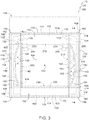
- Fig. 3 is a schematic transverse cross-sectional view of modular fuselage assembly 100 of Fig. 2 taken along line 3-3 of Fig. 2
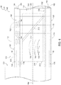
- Fig. 4 is a schematic longitudinal cross-sectional view of modular fuselage assembly 100 of Figs. 2-3 taken along line 4-4 of Fig. 3 .
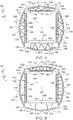
- Figs. 5-7 are less schematic transverse cross-sectional views of examples of modular fuselage assemblies 100 according to the present disclosure.
- modular fuselage assemblies 100 include a plurality of fuselage lobes 110 and a plurality of longerons 180, both of which may extend along a longitudinal axis 102 of the fuselage assembly.
- Each fuselage lobe 110 includes a plurality of frame members 130 and a lobe skin 170.
- Lobe skin 170 may be operatively attached to frame members 130 and/or may form and/or define an external surface 120 of each fuselage lobe 110.
- Figs. 2-7 modular fuselage assemblies 100 include a plurality of fuselage lobes 110 and a plurality of longerons 180, both of which may extend along a longitudinal axis 102 of the fuselage assembly.
- Each fuselage lobe 110 includes a plurality of frame members 130 and a lobe skin 170.
- Lobe skin 170 may be operatively attached to frame members 130 and/or may form and/or define an external surface 120 of each fuselage lobe 110.
- At least two fuselage lobes 110 may be operatively attached to each longeron 180, and fuselage lobes 110 and longerons 180 may at least partially bound, define, and/or surround a cargo hold 104 that may be defined within modular fuselage assembly 100.
- Modular fuselage assemblies 100 may provide several benefits over conventional fuselage assemblies of conventional aircraft. As an example and as discussed in more detail herein, it may be straightforward, effective, and/or efficient to form and/or define modular fuselage assemblies 100 that have and/or define a non-circular transverse cross-sectional shape.
- This non-circular transverse cross-sectional shape may include a plurality of arcuate regions that may be defined by fuselage lobes 110 and/or that may be interconnected at longerons 180.
- Such a configuration may decrease a wetted surface area of modular fuselage assembly 100, may decrease wind resistance of the modular fuselage assembly, and/or may decrease fuel burn in aircraft 10 that include the modular fuselage assembly when compared to conventional fuselages of conventional that are circular, or at least substantially circular, in transverse cross-section.
- modular fuselage assemblies 100 may permit a relatively small number of components, namely, fuselage lobes 110 and longerons 180, to be assembled in a variety of configurations to form and/or define a variety of different fuselages for aircraft 10.
- a number of frame members 130 within fuselage lobes 110 simply may be increased to increase a length of modular fuselage assembly 100.
- simple replacement of a portion of the frame members 130 within a given fuselage lobe 110 with differently shaped frame members 130 may permit formation of more complex fuselage shapes, such as those that may include a flight deck region.
- the simple replacement of a portion of the frame members 130 within the given fuselage lobe 110 with differently functioned frame members 130 may permit inclusion of wings, tails, and/or landing gear within the modular fuselage assembly.
- modular fuselage assemblies 100 may permit and/or facilitate formation of the flight deck region and/or attachment of wings, tails, and/or landing gear without inclusion of structure within cargo hold 104 of the aircraft, making modular fuselage assemblies 100 more efficient for use within freighter aircraft configured to haul freight.
- Frame members 130 may include any suitable structure that may be operatively attached to lobe skin 170, that may be operatively attached to longerons 180, that may operatively attach fuselage lobes 110 to longerons 180, and/or that may provide structural support for modular fuselage assembly 100 and/or for fuselage lobes 110 thereof. As illustrated collectively by Figs. 1-7 , frame members 130, or each frame member 130, may extend perpendicular, or at least substantially perpendicular, to longitudinal axis 102. Additionally or alternatively, each frame member 130 may extend between a corresponding pair of longerons 180 and/or may operatively attach the corresponding pair of longerons 180 to one another.
- Frame members 130 and/or components thereof may be formed from and/or defined by any suitable material and/or materials.
- materials that may be included in frame members 130 and/or in any suitable component thereof include aluminum, aircraft grade aluminum, and/or a composite material.
- frame members 130 may include a compression member 140.
- Compression member 140 when present, may at least partially bound cargo hold 104.
- Compression member 140 may be configured to receive and/or to resist a compressive force that may be applied thereto, such as along an elongate axis thereof. Stated another way, and during operation of modular fuselage assembly 100, compression member 140 may be in compression and/or may receive the compressive force.
- An example of compression member 140 includes a linear compression member 140.
- Further examples of compression member 140 include an elongate compression member, a linear compression member, and/or an at least substantially linear compression member.
- internal pressure may deform the modular fuselage assemblies and/or may urge the modular fuselage assemblies toward a more circular transverse cross-sectional shape (e.g., by urging longerons 180 toward one another).
- the inclusion of compression members 140 in frame members 130 may resist a potential for such deformation of the modular fuselage assemblies.
- frame members 130 may include a tension member 150.
- Tension member 150 may be operatively attached to and/or may mechanically support lobe skin 170. Additionally or alternatively, tension member 150 may be shaped such that each fuselage lobe 110 and/or lobe skin 170 thereof has and/or defines a convex external surface 156, and it is within the scope of the present disclosure that fuselage lobes 110 collectively may define a modular fuselage assembly 100 with a non-circular and/or scalloped transverse cross-sectional shape, as perhaps best illustrated in Figs. 5-7 .
- Tension member 150 may be configured to resist a tensile force that may be applied thereto, such as between ends thereof. Stated another way, and during operation of modular fuselage assembly 100, tension member 150 may be in tension and/or may receive the tensile force.
- tension member 150 includes an arcuate tension member 150.
- compression member 140 may have and/or define a first compression member end 142 and a second compression member end 144.
- tension member 150 may have and/or define a first tension member end 152 and a second tension member end 154.
- First tension member end 152 may be operatively attached to first compression member end 142.
- second tension member end 154 may be operatively attached to second compression member end 144.
- frame members 130 may include a frame member brace structure 160.
- Frame member brace structure 160 when present, may be configured to operatively interconnect compression member 140 and tension member 150, such as to increase a rigidity of each frame member 130.
- An example of frame member brace structure 160 includes a stanchion 162, or a plurality of stanchions 162, as illustrated in Figs. 3 and 6 .
- Stanchions 162 may extend between and/or be operatively attached to both compression member 140 and tension member 150.
- frame member brace structure 160 includes a truss 164, or a plurality of trusses 164, as illustrated in Figs. 3 , 5 , and 7 .
- Trusses 164 also may extend between and/or be operatively attached to both compression member 140 and tension member 150. Examples of trusses 164 include a triangular truss and/or a warren truss.
- frame members 130 may include and/or be single-piece, monolithic, and/or unitary frame members 132. Additionally or alternatively, frame members 130, or at least a subset of the plurality of frame members 130, may include and/or be a stamped and/or roll-formed metallic frame member that may be formed and/or defined from a sheet of metal.
- Longerons 180 may include any suitable structure that extends along longitudinal axis 102 of modular fuselage assembly 100, that is configured to be operatively attached to at least two fuselage lobes 110, and/or that at least partially bounds cargo hold 104.
- longerons 180 may include and/or be single-piece, monolithic, and/or unitary longerons 180. Stated another way, each longeron may extend along an entirety of a longitudinal length of modular fuselage assembly 100.
- longerons 180 may include and/or be a composite longeron 190, such as may be defined by a plurality of longeron sub-structures 192 that may be operatively attached to one another with a plurality of longeron fasteners 194, as illustrated in Figs. 2 and 4 . Stated another way, each longeron sub-structure 192 may extend along a portion, or a fraction, of the longitudinal length of modular fuselage assembly 100. Examples of longeron fasteners 194 include bolts, nuts, and/or rivets.
- Fuselage lobes 110 may be operatively attached to longerons 180 in any suitable manner.
- one or more lobe fasteners 128 may operatively attach each fuselage lobe 110 to corresponding longerons 180.
- Examples of lobe fasteners 128 include bolts, nuts, and/or rivets.
- modular fuselage assemblies 100 may include a longitudinal brace structure 210.
- Longitudinal brace structure 210 when present, may extend along at least a fraction, or even an entirety of longitudinal axis 102, or the longitudinal length, of modular fuselage assembly 100.
- longitudinal brace structure 210 may be operatively attached to the plurality of frame members 130 within a given fuselage lobe 110, to at least a subset of the plurality of frame members within the given fuselage lobe, or even to all of the plurality of frame members within the given fuselage lobe.
- Longitudinal brace structure 210 also may be referred to herein as a shear web and may be configured to brace frame members 130, to support load distribution along the longitudinal length of modular fuselage assembly 100, and/or to resist bending and/or twisting of the modular fuselage assembly about and/or along longitudinal axis 102.
- longitudinal brace structure 210 may include and/or be a continuous, a stamped, a monolithic, a unitary, a roll-formed, and/or a formed longitudinal brace structure 216, such as may extend along an entirety of the longitudinal length of the modular fuselage assembly.
- longitudinal brace structure 210 may include and/or be a plurality of strips 212 of bracing material. Strips 212 of bracing material may extend at a skew angle 214 relative to longitudinal axis 102 of modular fuselage assembly 100, as illustrated in Figs. 4 and 8 .
- longitudinal brace structure 210 may bound, or at least partially bound, cargo hold 104. Such a configuration may protect frame members 130 and/or lobe skin 170 from cargo 80 that may be positioned within cargo hold 104. Stated another way, the presence of longitudinal brace structure 210 may decrease a potential for damage to frame members 130 and/or lobe skin 170 that may be caused by contact with and/or impact by cargo 80.
- modular fuselage assembly 100 may include, may form, and/or may define a crane rail 220.
- Crane rail 220 may extend along the length of modular fuselage assembly 100, along the length of at least one, or even two, longerons 180 of the modular fuselage assembly, and/or along the length of cargo hold 104.
- modular fuselage assembly 100 also may include a cargo transport structure 224.
- Cargo transport structure 224 may be operatively, or rollingly, attached to crane rail 220 and may be configured to move cargo 80 within cargo hold 104 and/or along longitudinal axis 102 of modular fuselage assembly 100.
- fuselage lobes 110 include lobe skin 170 that may be operatively attached to the plurality of frame members 130 within a given fuselage lobe 110 and/or that may define external surface 120 of each fuselage lobe.
- lobe skin 170 may include and/or be a unitary, a monolithic, and/or a continuous lobe skin 170 that may extend along an entirety of longitudinal axis 102 and/or along an entirety of the longitudinal length of each fuselage lobe.
- lobe skin 170 may include a plurality of sub-skins 172, each of which may be operatively attached to a subset of the plurality of frame members 130 and/or each of which may extend along a fraction of the longitudinal length of each fuselage lobe 110, as illustrated in Fig. 2 .
- the subset of the plurality of frame members 130 include at least 2, at least 3, at least 4, at least 5, at least 6, at least 10%, at least 25%, and/or at least 50% of the plurality of frame members.
- the fraction of the longitudinal length of each fuselage lobe include at least 5%, at least 10%, at least 20%, at least 30%, at least 40%, and/or at least 50% of the longitudinal length of each fuselage lobe.
- At least one longeron 180 may be internal to a skin mold line 174 of lobe skin 170.
- modular fuselage assembly 100 may include thermal insulation 200, which may extend between the at least one longeron 180 and lobe skin 170, that may at least partially define a region 108 of an outer surface 106 of the modular fuselage assembly, and/or that may thermally insulate the at least one longeron 180.
- at least one longeron 180 may define, or at least partially define, region 108 of outer surface 106 of modular fuselage assembly 100. Stated another way, the at least one longeron 180 may be at skin mold line 174 of lobe skin 170.
- the plurality of fuselage lobes 110 may include a top lobe 112, a bottom lobe 114, a left side lobe 116, and a right side lobe 118, as collectively illustrated in Figs. 2-7 .
- the plurality of longerons 180 may include an upper left longeron 182, an upper right longeron 184, a lower left longeron 186, and a lower right longeron 188.
- upper left longeron 182 may be operatively attached to top lobe 112 and also to left side lobe 116
- upper right longeron 184 may be operatively attached to top lobe 112 and also to right side lobe 118.
- lower left longeron 186 may be operatively attached to bottom lobe 114 and also to left side lobe 116 and lower right longeron 188 may be operatively attached to bottom lobe 114 and also to right side lobe 118.
- modular fuselage assemblies 100 may have a uniform, an at least substantially uniform, a constant, and/or an at least substantially constant transverse cross-sectional shape along the longitudinal length of the modular fuselage assemblies.
- modular fuselage assemblies 100 may include two or more distinct, or different, regions.
- these distinct regions may be formed and/or defined simply by replacing and/or modifying a portion, or a region, of a given fuselage lobe 110 and/or of corresponding frame members 130 and/or lobe skin 170 of the given fuselage lobe, thereby permitting rapid, efficient, and/or cost-effective modification and/or assembly of modular fuselage assemblies 100.
- the replacement and/or modified portions of the given fuselage lobe 110 may modify external surface 120 of modular fuselage assembly 100 and/or external surface 120 of the given fuselage lobe without, or without necessarily, also modifying a shape of cargo hold 104.
- modular fuselage assemblies 100 may include a top lobe 112 that includes both a top lobe cargo region 122 and a top lobe flight deck region 124, as illustrated in Figs. 2-4 , and 13-15 .
- Top lobe cargo region 122 may have and/or define a cargo region shape that differs from a flight deck region shape of top lobe flight deck region 124.
- a transverse cross-sectional area of modular fuselage assembly 100 as measured within top lobe flight deck region 124 may be greater than a transverse cross-sectional area of the modular fuselage assembly as measured within top lobe cargo region 122.
- a transverse cross-section of top lobe cargo region 122 may be uniform, or at least substantially uniform, along a longitudinal length thereof.
- a transverse cross-section of top lobe flight deck region 124 may vary along the longitudinal length thereof, as illustrated.
- modular fuselage assemblies 100 may include a wing-receiving region 126 configured to receive a wing 30, as illustrated in Figs. 2 , 4 , and 14 .
- Wing-receiving region 126 may be formed and/or defined in, within, and/or by at least one fuselage lobe 110 of modular fuselage assemblies 100.
- the at least one fuselage lobe 110 may include top lobe 112 and/or bottom lobe 114, and modular fuselage assemblies 100 may be configured such that wing-receiving region 126 does not extend into cargo hold 104 and/or such that the transverse cross-sectional shape of a region of cargo hold 104 that is at least partially defined by wing-receiving region 126 is the same, or at least substantially the same, as the transverse cross-sectional shape of a remainder of the cargo hold. Additionally or alternatively, wing-receiving region 126 may permit wing 30 to penetrate the fuselage loft surface, and reduce drag, without interruption, or without a change in, the structure of longerons 180. Such a configuration may facilitate manufacturing of modular fuselage assemblies 100 and/or may permit longerons 180 to be the primary structures that carry, or that support, longitudinal fuselage bending loads.
- modular fuselage assemblies 100 may include a floor structure 230.
- Floor structure 230 may be operatively attached to and/or at least partially defined by bottom lobe 114 of modular fuselage assemblies 100 and may form and/or define a floor surface 232 configured to support personnel, passengers, and/or cargo 80.
- Floor structure 230 and/or floor surface 232 thereof may at least partially bound and/or define cargo hold 104, as illustrated.
- Fig. 16 is a flowchart depicting methods 300 of assembling a modular fuselage assembly, such as modular fuselage assembly 100 of Figs. 1-15 , according to the present disclosure.
- Methods 300 include providing frame members at 310 and providing longerons at 320.
- Methods 300 also include operatively attaching frame members to longerons at 330 and may include operatively attaching a lobe skin at 340 and/or operatively attaching an additional structure at 350.
- Providing the frame members at 310 may include providing a plurality of frame members. Examples of the frame members are disclosed herein with reference to frame members 130 of Figs. 2-8 and 11-12 .
- the providing the frame members at 310 may include providing the plurality of frame members as a part of, or as an assembly that defines, a plurality of fuselage lobes, examples of which are disclosed herein with reference to fuselage lobes 110 of Figs. 2-8 and 11-12 .
- each fuselage lobe may include a subset of the plurality of frame members and a lobe skin.
- the lobe skin may be operatively attached to the subset of the plurality of frame members and may extend along, may form, and/or may define an external surface of each fuselage lobe. Examples of the lobe skin are disclosed herein with reference to lobe skin 170 of Figs. 2-7 and 11-12 .
- Providing the longerons at 320 may include providing a plurality of longerons. Examples of the longerons are disclosed herein with reference to longerons 180 of Figs. 2-8 .
- Operatively attaching the frame members to the longerons at 330 may include operatively attaching each frame member of the plurality of frame members to at least two longerons of the plurality of longerons. This may include operatively attaching such that the plurality of longerons extends along a longitudinal axis of the modular fuselage assembly and/or such that the plurality of frame members extends perpendicular, or at least substantially perpendicular, to the longitudinal axis of the modular fuselage assembly.
- the operatively attaching at 330 may include operatively attaching at least two fuselage lobes to each longeron. Additionally or alternatively, the operatively attaching at 330 may include operatively attaching each fuselage lobe to at least two longerons.
- the providing the frame members at 310 may include providing the plurality of frame members independent from, separate from, and/or without the lobe skin.
- methods 300 also may include operatively attaching the lobe skin at 340.
- the operatively attaching the lobe skin at 340 may be performed subsequent to the operatively attaching at 330 and/or may include operatively attaching the lobe skin to an external surface of the plurality of frame members. This may include operatively attaching to from and/or define an outer surface of the modular fuselage assembly.
- Operatively attaching the additional structure at 350 may include operatively attaching any suitable additional structure to the modular fuselage assembly in any suitable manner and/or in any suitable sequence.
- the operatively attaching at 350 may include operatively attaching any suitable structure and/or structures that are disclosed, described, and/or illustrated herein as being operatively attached to the modular fuselage assembly and/or as forming a portion of an aircraft that includes the modular fuselage assembly. This may include operatively attaching the suitable structure and/or structures to at least one frame member of the plurality of frame members, to the plurality of frame members, to at least one longeron of the plurality of longerons, and/or to the plurality of longerons.
- the terms “adapted” and “configured” mean that the element, component, or other subject matter is designed and/or intended to perform a given function. Thus, the use of the terms “adapted” and “configured” should not be construed to mean that a given element, component, or other subject matter is simply “capable of” performing a given function but that the element, component, and/or other subject matter is specifically selected, created, implemented, utilized, programmed, and/or designed for the purpose of performing the function. It is also within the scope of the present disclosure that elements, components, and/or other recited subject matter that is recited as being adapted to perform a particular function may additionally or alternatively be described as being configured to perform that function, and vice versa. Similarly, subject matter that is recited as being configured to perform a particular function may additionally or alternatively be described as being operative to perform that function.
- the phrase "at least one,” in reference to a list of one or more entities should be understood to mean at least one entity selected from any one or more of the entity in the list of entities, but not necessarily including at least one of each and every entity specifically listed within the list of entities and not excluding any combinations of entities in the list of entities.
- This definition also allows that entities may optionally be present other than the entities specifically identified within the list of entities to which the phrase "at least one" refers, whether related or unrelated to those entities specifically identified.
- At least one of A and B may refer, in one embodiment, to at least one, optionally including more than one, A, with no B present (and optionally including entities other than B); in another embodiment, to at least one, optionally including more than one, B, with no A present (and optionally including entities other than A); in yet another embodiment, to at least one, optionally including more than one, A, and at least one, optionally including more than one, B (and optionally including other entities).
- each of the expressions “at least one of A, B, and C,” “at least one of A, B, or C,” “one or more of A, B, and C,” “one or more of A, B, or C” and “A, B, and/or C” may mean A alone, B alone, C alone, A and B together, A and C together, B and C together, A, B, and C together, and optionally any of the above in combination with at least one other entity.
- the phrase, "for example,” the phrase, “as an example,” and/or simply the term “example,” when used with reference to one or more components, features, details, structures, embodiments, and/or methods according to the present disclosure, are intended to convey that the described component, feature, detail, structure, embodiment, and/or method is an illustrative, non-exclusive example of components, features, details, structures, embodiments, and/or methods according to the present disclosure.
- an object that is at least substantially formed from a material includes objects for which at least 75% of the objects are formed from the material and also includes objects that are completely formed from the material.
- a first length that is at least substantially as long as a second length includes first lengths that are within 75% of the second length and also includes first lengths that are as long as the second length.
- the phrase, "operatively attached” may mean that two structures, members, and/or components may be attached to one another and/or mechanically coupled to one another. It is within the scope of the present disclosure that the phrase, "operatively attached” may refer to two structures that are mechanically coupled to one another such that the two structures contact, physically contact, and/or directly contact one another. In such an example, the two structures also may be referred to herein as being “directly and operatively attached” to one another. It is also within the scope of the present disclosure that the phrase, "operatively attached” may refer to two structures that are mechanically coupled to one another via one or more intermediate structures and/or such that the two structures do not contact, do not physically contact, and/or do not directly contact one another. In such an example, the two structures also may be referred to herein as being “indirectly and operatively attached” to one another.
Landscapes
- Engineering & Computer Science (AREA)
- Aviation & Aerospace Engineering (AREA)
- Mechanical Engineering (AREA)
- Manufacturing & Machinery (AREA)
- Transportation (AREA)
- Automatic Assembly (AREA)
- Body Structure For Vehicles (AREA)
Abstract
Description
- The present disclosure relates generally to modular fuselage assemblies for aircraft, to aircraft including modular fuselage assemblies, and/or to methods of assemblies modular fuselage assemblies.
- Passenger transport is the largest market for commercial aircraft. As such, commercial aircraft, regardless of their intended final use, generally are designed and/or constructed to meet the needs of the passenger aircraft market. These designs then are modified for other applications, such as commercial freighter aircraft. This permits an aircraft manufacturer to produce a number of different sub-models of aircraft all based upon a single overall aircraft design.
- While effective at meeting the needs of various market segments, this approach generally results in design compromises that may not be functionally ideal for all market segments. As an example, the need for separate cabin and luggage space within passenger transport aircraft means that commercial freighter aircraft generally include two cargo holds, one within the area utilized as cabin space within passenger transport aircraft and one within the area utilized as luggage space within passenger transport aircraft. Such a configuration is inefficient from a freight transport perspective and somewhat arbitrarily limits the size of freight that may be transported by commercial freighter aircraft.
- As another example, a given model of aircraft generally is a one-size-fits-all solution with respect to the overall dimensions of the aircraft, with these dimensions being selected primarily based upon passenger transport needs. Once again, these passenger transport needs may somewhat arbitrarily limit the usefulness of the aircraft for other purposes, such as freight transport. Thus, there exists a need for modular fuselage assemblies for aircraft and/or for methods of assembling modular fuselage assemblies.
- Modular fuselage assemblies for aircraft and methods of assembling modular fuselage assemblies are discussed herein. A modular fuselage assembly may include a plurality of fuselage lobes that may extend along a longitudinal axis of the modular fuselage assembly. Each fuselage lobe may include a plurality of frame members and a lobe skin that is operatively attached to the plurality of frame members and defines an external surface of the fuselage lobe. The modular fuselage assembly also may include a plurality of longerons extending along the longitudinal axis of the modular fuselage assembly. At least two fuselage lobes may be operatively attached to each longeron and the plurality of fuselage lobes and the plurality of longerons may at least partially bound a cargo hold defined within the modular fuselage assembly.
- The methods include methods of assembling the modular fuselage assemblies. These methods may include providing the plurality of frame members and/or providing the plurality of longerons. These methods also may include operatively attaching each frame member to at least two longerons such that the plurality of longerons extends along the longitudinal axis of the modular fuselage assembly.
-
-
Fig. 1 is a schematic illustration of an example of an aircraft that may include and/or utilize modular fuselage assemblies, according to the present disclosure. -
Fig. 2 is a schematic side view of examples of a modular fuselage assembly according to the present disclosure. -
Fig. 3 is a schematic transverse cross-sectional view of the modular fuselage assembly ofFig. 2 taken along line 3-3 ofFig. 2 . -
Fig. 4 is a schematic longitudinal cross-sectional view of the modular fuselage assembly ofFigs. 2-3 taken along line 4-4 ofFig. 3 . -
Fig. 5 is a less schematic transverse cross-sectional view of an example of a modular fuselage assembly according to the present disclosure. -
Fig. 6 is a less schematic transverse cross-sectional view of an example of a modular fuselage assembly according to the present disclosure. -
Fig. 7 is a less schematic transverse cross-sectional view of an example of a modular fuselage assembly according to the present disclosure. -
Fig. 8 is a less schematic longitudinal cross-sectional view of an example of a modular fuselage assembly according to the present disclosure. -
Fig. 9 is a less schematic transverse cross-sectional view of an example of a modular fuselage assembly illustrating incorporation of a crane rail, according to the present disclosure. -
Fig. 10 is a less schematic and partially cut-away side view of an aircraft that includes the modular fuselage assembly and the crane rail ofFig. 9 . -
Fig. 11 is a less schematic transverse cross-sectional view of an example of a region of a modular fuselage assembly according to the present disclosure. -
Fig. 12 is a less schematic transverse cross-sectional view of an example of a region of a modular fuselage assembly according to the present disclosure. -
Fig. 13 is a schematic illustration of an example of a portion of a modular fuselage assembly illustrating both a top lobe deck region and a top lobe cargo region, according to the present disclosure. -
Fig. 14 is a schematic illustration of another example of a portion of a modular fuselage assembly illustrating a top lobe deck region, a top lobe cargo region, and a wing-receiving region, according to the present disclosure. -
Fig. 15 is a transverse cross-sectional view of the modular fuselage assembly ofFig. 13 taken along line 15-15 ofFig. 13 . -
Fig. 16 is a flowchart depicting methods of assembling a modular fuselage assembly, according to the present disclosure. -
Figs. 1-16 provide illustrative, non-exclusive examples ofaircraft 10, ofmodular fuselage assemblies 100, and/or ofmethods 300, according to the present disclosure. Elements that serve a similar, or at least substantially similar, purpose are labeled with like numbers in each ofFigs. 1-16 , and these elements may not be discussed in detail herein with reference to each ofFigs. 1-16 . Similarly, all elements may not be labeled in each ofFigs. 1-16 , but reference numerals associated therewith may be utilized herein for consistency. Elements, components, and/or features that are discussed herein with reference to one or more ofFigs. 1-16 may be included in and/or utilized with any ofFigs. 1-16 without departing from the scope of the present disclosure. - In general, elements that are likely to be included in a given (i.e., a particular) embodiment are illustrated in solid lines, while elements that are optional to a given embodiment are illustrated in dashed lines. However, elements that are shown in solid lines are not essential to all embodiments, and an element shown in solid lines may be omitted from a given embodiment without departing from the scope of the present disclosure.
-
Fig. 1 is a schematic illustration of an example of anaircraft 10 that may include and/or utilizemodular fuselage assemblies 100, according to the present disclosure. Examples ofmodular fuselage assemblies 100 are illustrated inFigs. 2-14 and discussed in more detail herein with reference thereto. -
Aircraft 10 may include afuselage 20 in the form ofmodular fuselage assembly 100.Aircraft 10 also may include at least onewing 30, which may be operatively attached to and/or may extend fromfuselage 20 and/or at least oneengine 70, which may be operatively attached tofuselage 20, such as via acorresponding wing 30.Aircraft 10 also may include atail assembly 40 that may be operatively attached to and/or at least partially defined byfuselage 20.Tail assembly 40 may include at least onevertical stabilizer 50 and/or at least onehorizontal stabilizer 60. -
Fig. 2 is a schematic side view of examples of amodular fuselage assembly 100 according to the present disclosure.Fig. 3 is a schematic transverse cross-sectional view ofmodular fuselage assembly 100 ofFig. 2 taken along line 3-3 ofFig. 2 , andFig. 4 is a schematic longitudinal cross-sectional view ofmodular fuselage assembly 100 ofFigs. 2-3 taken along line 4-4 ofFig. 3 .Figs. 5-7 are less schematic transverse cross-sectional views of examples ofmodular fuselage assemblies 100 according to the present disclosure. - As illustrated collectively by
Figs. 2-7 ,modular fuselage assemblies 100 include a plurality offuselage lobes 110 and a plurality oflongerons 180, both of which may extend along alongitudinal axis 102 of the fuselage assembly. Eachfuselage lobe 110 includes a plurality offrame members 130 and alobe skin 170.Lobe skin 170 may be operatively attached toframe members 130 and/or may form and/or define anexternal surface 120 of eachfuselage lobe 110. As perhaps best illustrated byFigs. 2 and5-7 , at least twofuselage lobes 110 may be operatively attached to eachlongeron 180, andfuselage lobes 110 andlongerons 180 may at least partially bound, define, and/or surround acargo hold 104 that may be defined withinmodular fuselage assembly 100. -
Modular fuselage assemblies 100, which are disclosed herein, may provide several benefits over conventional fuselage assemblies of conventional aircraft. As an example and as discussed in more detail herein, it may be straightforward, effective, and/or efficient to form and/or definemodular fuselage assemblies 100 that have and/or define a non-circular transverse cross-sectional shape. This non-circular transverse cross-sectional shape may include a plurality of arcuate regions that may be defined byfuselage lobes 110 and/or that may be interconnected atlongerons 180. Such a configuration may decrease a wetted surface area ofmodular fuselage assembly 100, may decrease wind resistance of the modular fuselage assembly, and/or may decrease fuel burn inaircraft 10 that include the modular fuselage assembly when compared to conventional fuselages of conventional that are circular, or at least substantially circular, in transverse cross-section. - As another example, the modular nature of
modular fuselage assemblies 100 may permit a relatively small number of components, namely,fuselage lobes 110 andlongerons 180, to be assembled in a variety of configurations to form and/or define a variety of different fuselages foraircraft 10. As a more specific example, a number offrame members 130 withinfuselage lobes 110 simply may be increased to increase a length ofmodular fuselage assembly 100. - As another example, and as discussed in more detail herein, simple replacement of a portion of the
frame members 130 within a givenfuselage lobe 110 with differently shapedframe members 130 may permit formation of more complex fuselage shapes, such as those that may include a flight deck region. As yet another example, and as discussed in more detail herein, the simple replacement of a portion of theframe members 130 within the givenfuselage lobe 110 with differently functionedframe members 130 may permit inclusion of wings, tails, and/or landing gear within the modular fuselage assembly. - As another example,
modular fuselage assemblies 100 may permit and/or facilitate formation of the flight deck region and/or attachment of wings, tails, and/or landing gear without inclusion of structure withincargo hold 104 of the aircraft, makingmodular fuselage assemblies 100 more efficient for use within freighter aircraft configured to haul freight. -
Frame members 130 may include any suitable structure that may be operatively attached tolobe skin 170, that may be operatively attached tolongerons 180, that may operatively attachfuselage lobes 110 tolongerons 180, and/or that may provide structural support formodular fuselage assembly 100 and/or forfuselage lobes 110 thereof. As illustrated collectively byFigs. 1-7 ,frame members 130, or eachframe member 130, may extend perpendicular, or at least substantially perpendicular, tolongitudinal axis 102. Additionally or alternatively, eachframe member 130 may extend between a corresponding pair oflongerons 180 and/or may operatively attach the corresponding pair oflongerons 180 to one another. -
Frame members 130 and/or components thereof may be formed from and/or defined by any suitable material and/or materials. Examples of materials that may be included inframe members 130 and/or in any suitable component thereof include aluminum, aircraft grade aluminum, and/or a composite material. - As illustrated in dashed lines in
Fig. 3 and in solid lines inFigs. 5-7 ,frame members 130, or at least a subset of the plurality offrame members 130, may include acompression member 140.Compression member 140, when present, may at least partially boundcargo hold 104.Compression member 140 may be configured to receive and/or to resist a compressive force that may be applied thereto, such as along an elongate axis thereof. Stated another way, and during operation ofmodular fuselage assembly 100,compression member 140 may be in compression and/or may receive the compressive force. An example ofcompression member 140 includes alinear compression member 140. Further examples ofcompression member 140 include an elongate compression member, a linear compression member, and/or an at least substantially linear compression member. - During operation of
modular fuselage assemblies 100 with non-circular transverse cross-sectional shapes, internal pressure may deform the modular fuselage assemblies and/or may urge the modular fuselage assemblies toward a more circular transverse cross-sectional shape (e.g., by urginglongerons 180 toward one another). The inclusion ofcompression members 140 inframe members 130 may resist a potential for such deformation of the modular fuselage assemblies. - As also illustrated in dashed lines in
Fig. 3 and in solid lines inFigs. 5-7 ,frame members 130, or at least a subset of the plurality offrame members 130, may include atension member 150.Tension member 150 may be operatively attached to and/or may mechanically supportlobe skin 170. Additionally or alternatively,tension member 150 may be shaped such that eachfuselage lobe 110 and/orlobe skin 170 thereof has and/or defines a convexexternal surface 156, and it is within the scope of the present disclosure thatfuselage lobes 110 collectively may define amodular fuselage assembly 100 with a non-circular and/or scalloped transverse cross-sectional shape, as perhaps best illustrated inFigs. 5-7 . -
Tension member 150 may be configured to resist a tensile force that may be applied thereto, such as between ends thereof. Stated another way, and during operation ofmodular fuselage assembly 100,tension member 150 may be in tension and/or may receive the tensile force. An example oftension member 150 includes anarcuate tension member 150. - As illustrated in
Figs. 3-7 ,compression member 140 may have and/or define a firstcompression member end 142 and a secondcompression member end 144. Similarly,tension member 150 may have and/or define a firsttension member end 152 and a secondtension member end 154. Firsttension member end 152 may be operatively attached to firstcompression member end 142. Similarly, secondtension member end 154 may be operatively attached to secondcompression member end 144. - As illustrated in dashed lines in
Fig. 3 and in solid lines inFigs. 5-7 ,frame members 130, or at least a subset of the plurality offrame members 130, may include a framemember brace structure 160. Framemember brace structure 160, when present, may be configured to operatively interconnectcompression member 140 andtension member 150, such as to increase a rigidity of eachframe member 130. An example of framemember brace structure 160 includes astanchion 162, or a plurality ofstanchions 162, as illustrated inFigs. 3 and6 .Stanchions 162 may extend between and/or be operatively attached to bothcompression member 140 andtension member 150. Another example of framemember brace structure 160 includes atruss 164, or a plurality oftrusses 164, as illustrated inFigs. 3 ,5 , and7 .Trusses 164 also may extend between and/or be operatively attached to bothcompression member 140 andtension member 150. Examples oftrusses 164 include a triangular truss and/or a warren truss. - As illustrated in dashed lines in
Fig. 3 and in solid lines inFig. 7 ,frame members 130, or at least a subset of the plurality offrame members 130, may include and/or be single-piece, monolithic, and/orunitary frame members 132. Additionally or alternatively,frame members 130, or at least a subset of the plurality offrame members 130, may include and/or be a stamped and/or roll-formed metallic frame member that may be formed and/or defined from a sheet of metal. -
Longerons 180 may include any suitable structure that extends alonglongitudinal axis 102 ofmodular fuselage assembly 100, that is configured to be operatively attached to at least twofuselage lobes 110, and/or that at least partially boundscargo hold 104. As examples,longerons 180 may include and/or be single-piece, monolithic, and/orunitary longerons 180. Stated another way, each longeron may extend along an entirety of a longitudinal length ofmodular fuselage assembly 100. As another example,longerons 180 may include and/or be acomposite longeron 190, such as may be defined by a plurality oflongeron sub-structures 192 that may be operatively attached to one another with a plurality oflongeron fasteners 194, as illustrated inFigs. 2 and4 . Stated another way, each longeron sub-structure 192 may extend along a portion, or a fraction, of the longitudinal length ofmodular fuselage assembly 100. Examples oflongeron fasteners 194 include bolts, nuts, and/or rivets. -
Fuselage lobes 110 may be operatively attached tolongerons 180 in any suitable manner. As an example, and as illustrated inFigs. 2-4 , one ormore lobe fasteners 128 may operatively attach eachfuselage lobe 110 tocorresponding longerons 180. Examples oflobe fasteners 128 include bolts, nuts, and/or rivets. - As illustrated schematically in
Figs. 3-4 and less schematically inFig. 8 ,modular fuselage assemblies 100 may include alongitudinal brace structure 210.Longitudinal brace structure 210, when present, may extend along at least a fraction, or even an entirety oflongitudinal axis 102, or the longitudinal length, ofmodular fuselage assembly 100. Additionally or alternatively,longitudinal brace structure 210 may be operatively attached to the plurality offrame members 130 within a givenfuselage lobe 110, to at least a subset of the plurality of frame members within the given fuselage lobe, or even to all of the plurality of frame members within the given fuselage lobe.Longitudinal brace structure 210 also may be referred to herein as a shear web and may be configured to braceframe members 130, to support load distribution along the longitudinal length ofmodular fuselage assembly 100, and/or to resist bending and/or twisting of the modular fuselage assembly about and/or alonglongitudinal axis 102. - In some examples,
longitudinal brace structure 210 may include and/or be a continuous, a stamped, a monolithic, a unitary, a roll-formed, and/or a formedlongitudinal brace structure 216, such as may extend along an entirety of the longitudinal length of the modular fuselage assembly. In some examples,longitudinal brace structure 210 may include and/or be a plurality ofstrips 212 of bracing material.Strips 212 of bracing material may extend at askew angle 214 relative tolongitudinal axis 102 ofmodular fuselage assembly 100, as illustrated inFigs. 4 and8 . - As illustrated,
longitudinal brace structure 210 may bound, or at least partially bound,cargo hold 104. Such a configuration may protectframe members 130 and/orlobe skin 170 fromcargo 80 that may be positioned withincargo hold 104. Stated another way, the presence oflongitudinal brace structure 210 may decrease a potential for damage to framemembers 130 and/orlobe skin 170 that may be caused by contact with and/or impact bycargo 80. - As illustrated in dashed lines in
Fig. 3 and in solid lines inFigs. 9-10 ,modular fuselage assembly 100 may include, may form, and/or may define acrane rail 220.Crane rail 220 may extend along the length ofmodular fuselage assembly 100, along the length of at least one, or even two,longerons 180 of the modular fuselage assembly, and/or along the length ofcargo hold 104. - As illustrated in dashed lines in
Fig. 3 and in solid lines inFig. 9 ,modular fuselage assembly 100 also may include acargo transport structure 224.Cargo transport structure 224 may be operatively, or rollingly, attached tocrane rail 220 and may be configured to movecargo 80 withincargo hold 104 and/or alonglongitudinal axis 102 ofmodular fuselage assembly 100. - As discussed,
fuselage lobes 110 includelobe skin 170 that may be operatively attached to the plurality offrame members 130 within a givenfuselage lobe 110 and/or that may defineexternal surface 120 of each fuselage lobe. In some examples,lobe skin 170 may include and/or be a unitary, a monolithic, and/or acontinuous lobe skin 170 that may extend along an entirety oflongitudinal axis 102 and/or along an entirety of the longitudinal length of each fuselage lobe. Additionally or alternatively, in some examples,lobe skin 170 may include a plurality ofsub-skins 172, each of which may be operatively attached to a subset of the plurality offrame members 130 and/or each of which may extend along a fraction of the longitudinal length of eachfuselage lobe 110, as illustrated inFig. 2 . Examples of the subset of the plurality offrame members 130 include at least 2, at least 3, at least 4, at least 5, at least 6, at least 10%, at least 25%, and/or at least 50% of the plurality of frame members. Examples of the fraction of the longitudinal length of each fuselage lobe include at least 5%, at least 10%, at least 20%, at least 30%, at least 40%, and/or at least 50% of the longitudinal length of each fuselage lobe. - As illustrated in dashed lines in
Figs. 3 and in solid lines inFig. 11 , at least onelongeron 180 may be internal to askin mold line 174 oflobe skin 170. In this configuration,modular fuselage assembly 100 may includethermal insulation 200, which may extend between the at least onelongeron 180 andlobe skin 170, that may at least partially define aregion 108 of anouter surface 106 of the modular fuselage assembly, and/or that may thermally insulate the at least onelongeron 180. Additionally or alternatively, and as illustrated in solid lines inFigs. 3 and12 , at least onelongeron 180 may define, or at least partially define,region 108 ofouter surface 106 ofmodular fuselage assembly 100. Stated another way, the at least onelongeron 180 may be atskin mold line 174 oflobe skin 170. - In some examples, the plurality of
fuselage lobes 110 may include atop lobe 112, abottom lobe 114, aleft side lobe 116, and aright side lobe 118, as collectively illustrated inFigs. 2-7 . In these examples, the plurality oflongerons 180 may include an upperleft longeron 182, an upperright longeron 184, a lowerleft longeron 186, and a lowerright longeron 188. As illustrated, upperleft longeron 182 may be operatively attached totop lobe 112 and also to leftside lobe 116, and upperright longeron 184 may be operatively attached totop lobe 112 and also toright side lobe 118. Similarly, lowerleft longeron 186 may be operatively attached tobottom lobe 114 and also to leftside lobe 116 and lowerright longeron 188 may be operatively attached tobottom lobe 114 and also toright side lobe 118. - It is within the scope of the present disclosure that
modular fuselage assemblies 100, according to the present disclosure, may have a uniform, an at least substantially uniform, a constant, and/or an at least substantially constant transverse cross-sectional shape along the longitudinal length of the modular fuselage assemblies. Alternatively, and as illustrated inFigs. 2-4 and13-15 ,modular fuselage assemblies 100 may include two or more distinct, or different, regions. As discussed herein, these distinct regions may be formed and/or defined simply by replacing and/or modifying a portion, or a region, of a givenfuselage lobe 110 and/or ofcorresponding frame members 130 and/orlobe skin 170 of the given fuselage lobe, thereby permitting rapid, efficient, and/or cost-effective modification and/or assembly ofmodular fuselage assemblies 100. As also discussed herein, the replacement and/or modified portions of the givenfuselage lobe 110 may modifyexternal surface 120 ofmodular fuselage assembly 100 and/orexternal surface 120 of the given fuselage lobe without, or without necessarily, also modifying a shape ofcargo hold 104. - As an example,
modular fuselage assemblies 100 may include atop lobe 112 that includes both a toplobe cargo region 122 and a top lobeflight deck region 124, as illustrated inFigs. 2-4 , and13-15 . Toplobe cargo region 122 may have and/or define a cargo region shape that differs from a flight deck region shape of top lobeflight deck region 124. As an example, a transverse cross-sectional area ofmodular fuselage assembly 100 as measured within top lobeflight deck region 124 may be greater than a transverse cross-sectional area of the modular fuselage assembly as measured within toplobe cargo region 122. As another example, a transverse cross-section of toplobe cargo region 122 may be uniform, or at least substantially uniform, along a longitudinal length thereof. However, a transverse cross-section of top lobeflight deck region 124 may vary along the longitudinal length thereof, as illustrated. - As another example,
modular fuselage assemblies 100 may include a wing-receivingregion 126 configured to receive awing 30, as illustrated inFigs. 2 ,4 , and14 . Wing-receivingregion 126 may be formed and/or defined in, within, and/or by at least onefuselage lobe 110 ofmodular fuselage assemblies 100. The at least onefuselage lobe 110 may includetop lobe 112 and/orbottom lobe 114, andmodular fuselage assemblies 100 may be configured such that wing-receivingregion 126 does not extend intocargo hold 104 and/or such that the transverse cross-sectional shape of a region ofcargo hold 104 that is at least partially defined by wing-receivingregion 126 is the same, or at least substantially the same, as the transverse cross-sectional shape of a remainder of the cargo hold. Additionally or alternatively, wing-receivingregion 126 may permitwing 30 to penetrate the fuselage loft surface, and reduce drag, without interruption, or without a change in, the structure oflongerons 180. Such a configuration may facilitate manufacturing ofmodular fuselage assemblies 100 and/or may permitlongerons 180 to be the primary structures that carry, or that support, longitudinal fuselage bending loads. - As illustrated in dashed lines in
Figs. 3-4 and in solid lines inFigs. 5-7 ,modular fuselage assemblies 100 may include afloor structure 230.Floor structure 230 may be operatively attached to and/or at least partially defined bybottom lobe 114 ofmodular fuselage assemblies 100 and may form and/or define afloor surface 232 configured to support personnel, passengers, and/orcargo 80.Floor structure 230 and/orfloor surface 232 thereof may at least partially bound and/or definecargo hold 104, as illustrated. -
Fig. 16 is aflowchart depicting methods 300 of assembling a modular fuselage assembly, such asmodular fuselage assembly 100 ofFigs. 1-15 , according to the present disclosure.Methods 300 include providing frame members at 310 and providing longerons at 320.Methods 300 also include operatively attaching frame members to longerons at 330 and may include operatively attaching a lobe skin at 340 and/or operatively attaching an additional structure at 350. - Providing the frame members at 310 may include providing a plurality of frame members. Examples of the frame members are disclosed herein with reference to frame
members 130 ofFigs. 2-8 and11-12 . - In some examples, the providing the frame members at 310 may include providing the plurality of frame members as a part of, or as an assembly that defines, a plurality of fuselage lobes, examples of which are disclosed herein with reference to
fuselage lobes 110 ofFigs. 2-8 and11-12 . In these examples, each fuselage lobe may include a subset of the plurality of frame members and a lobe skin. The lobe skin may be operatively attached to the subset of the plurality of frame members and may extend along, may form, and/or may define an external surface of each fuselage lobe. Examples of the lobe skin are disclosed herein with reference tolobe skin 170 ofFigs. 2-7 and11-12 . - Providing the longerons at 320 may include providing a plurality of longerons. Examples of the longerons are disclosed herein with reference to
longerons 180 ofFigs. 2-8 . - Operatively attaching the frame members to the longerons at 330 may include operatively attaching each frame member of the plurality of frame members to at least two longerons of the plurality of longerons. This may include operatively attaching such that the plurality of longerons extends along a longitudinal axis of the modular fuselage assembly and/or such that the plurality of frame members extends perpendicular, or at least substantially perpendicular, to the longitudinal axis of the modular fuselage assembly.
- When the providing the frame members at 310 includes providing the plurality of frame members as part of the plurality of fuselage lobes, the operatively attaching at 330 may include operatively attaching at least two fuselage lobes to each longeron. Additionally or alternatively, the operatively attaching at 330 may include operatively attaching each fuselage lobe to at least two longerons.
- In some examples, the providing the frame members at 310 may include providing the plurality of frame members independent from, separate from, and/or without the lobe skin. In these examples,
methods 300 also may include operatively attaching the lobe skin at 340. The operatively attaching the lobe skin at 340 may be performed subsequent to the operatively attaching at 330 and/or may include operatively attaching the lobe skin to an external surface of the plurality of frame members. This may include operatively attaching to from and/or define an outer surface of the modular fuselage assembly. - Operatively attaching the additional structure at 350 may include operatively attaching any suitable additional structure to the modular fuselage assembly in any suitable manner and/or in any suitable sequence. As an example, the operatively attaching at 350 may include operatively attaching any suitable structure and/or structures that are disclosed, described, and/or illustrated herein as being operatively attached to the modular fuselage assembly and/or as forming a portion of an aircraft that includes the modular fuselage assembly. This may include operatively attaching the suitable structure and/or structures to at least one frame member of the plurality of frame members, to the plurality of frame members, to at least one longeron of the plurality of longerons, and/or to the plurality of longerons.
- Illustrative, non-exclusive examples of inventive subject matter according to the present disclosure are described in the following enumerated paragraphs:
- A1. A modular fuselage assembly for an aircraft, the modular fuselage assembly comprising:
- a plurality of fuselage lobes extending along a longitudinal axis of the modular fuselage assembly, wherein each fuselage lobe of the plurality of fuselage lobes includes:
- (i) a plurality of frame members; and
- (ii) a lobe skin that is operatively attached to the plurality of frame members and defines an external surface of each fuselage lobe; and
- a plurality of longerons extending along the longitudinal axis of the modular fuselage assembly;
- wherein at least two fuselage lobes of the plurality of fuselage lobes are operatively, or directly and operatively, attached to each longeron of the plurality of longerons; and
- wherein the plurality of fuselage lobes and the plurality of longerons at least partially bound a cargo hold defined within the modular fuselage assembly.
- a plurality of fuselage lobes extending along a longitudinal axis of the modular fuselage assembly, wherein each fuselage lobe of the plurality of fuselage lobes includes:
- A2. The modular fuselage assembly of paragraph A1, wherein the plurality of fuselage lobes includes a top lobe, a bottom lobe, a left side lobe, and a right side lobe.
- A3. The modular fuselage assembly of paragraph A2, wherein the plurality of longerons includes:
- (i) an upper left longeron, which is operatively, or directly and operatively, attached to the top lobe and to the left side lobe;
- (ii) an upper right longeron, which is operatively, or directly and operatively, attached to the top lobe and to the right side lobe;
- (iii) a lower left longeron, which is operatively, or directly and operatively, attached to the bottom lobe and to the left side lobe; and
- (iv) a lower right longeron, which is operatively, or directly and operatively, attached to the bottom lobe and to the right side lobe.
- A4. The modular fuselage assembly of any of paragraphs A2-A3, wherein the top lobe includes a top lobe cargo region that defines a cargo region shape and a top lobe flight deck region that defines a flight deck region shape that differs from the cargo region shape.
- A5. The modular fuselage assembly of paragraph A4, wherein a transverse cross-sectional area of the modular fuselage assembly as measured within the top lobe flight deck region is greater than a transverse cross-sectional area of the modular fuselage assembly as measured within the top lobe cargo region.
- A6. The modular fuselage assembly of any of paragraphs A1-A5, wherein at least one fuselage lobe of the plurality of fuselage lobes further includes a wing-receiving region configured to be operatively attached to a wing of the aircraft.
- A7. The modular fuselage assembly of paragraph A6, wherein the at least one fuselage lobe includes at least one of a/the top lobe and a/the bottom lobe.
- A8. The modular fuselage assembly of any of paragraphs A1-A7, wherein each frame member of the plurality of frame members extends perpendicular, or at least substantially perpendicular, to the longitudinal axis of the modular fuselage assembly.
- A9. The modular fuselage assembly of any of paragraphs A1-A8, wherein at least a subset of the plurality of frame members includes a compression member.
- A10. The modular fuselage assembly of paragraph A9, wherein the compression member at least partially bounds the cargo hold.
- A11. The modular fuselage assembly of any of paragraphs A9-A10, wherein the compression member includes a linear compression member.
- A12. The modular fuselage assembly of any of paragraphs A9-A11, wherein each frame member of the at least the subset of the plurality of frame members includes a tension member.
- A13. The modular fuselage assembly of paragraph A12, wherein the compression member includes a first compression member end and a second compression member end, and further wherein the tension member includes a first tension member end, which is operatively, or directly and operatively, attached to the first compression member end, and a second tension member end, which is operatively, or directly and operatively, attached to the second compression member end.
- A14. The modular fuselage assembly of paragraph A13, wherein the tension member is an arcuate tension member.
- A15. The modular fuselage assembly of paragraph A14, wherein the arcuate tension member is shaped such that each fuselage lobe defines a convex external surface.
- A16. The modular fuselage assembly of any of paragraphs A13-A15, wherein the tension member is operatively, or directly and operatively, attached to the lobe skin.
- A17. The modular fuselage assembly of any of paragraphs A12-A16, wherein each frame member further includes a frame member brace structure configured to operatively interconnect the compression member and the tension member to increase a rigidity of each frame member.
- A18. The modular fuselage assembly of paragraph A17, wherein the frame member brace structure includes at least one of:
- (i) a stanchion, optionally wherein the stanchion extends between, and is operatively, or directly and operatively, attached to the compression member and the tension member;
- (ii) a plurality of stanchions, optionally wherein each stanchion of the plurality of stanchions extends between, and is operatively, or directly and operatively, attached to the compression member and the tension member;
- (iii) a truss, optionally wherein the truss extends between, and is operatively, or directly and operatively, attached to the compression member and the tension member;
- (iv) a triangular truss, optionally wherein the triangular truss extends between, and is operatively, or directly and operatively, attached to the compression member and the tension member; and
- (v) a Warren truss, optionally wherein the Warren truss extends between, and is operatively, or directly and operatively, attached to the compression member and the tension member.
- A19. The modular fuselage assembly of any of paragraphs A1-A18, wherein at least a subset of the plurality of frame members includes at least one of:
- (i) a single-piece frame member;
- (ii) a monolithic frame member; and
- (iii) a unitary frame member.
- A20. The modular fuselage assembly of any of paragraphs A1-A19, wherein at least a subset of the plurality of frame members includes at least one of:
- (i) a stamped metallic frame member defined from a sheet of metal; and
- (ii) a roll-formed metallic frame member defined from the sheet of metal.
- A21. The modular fuselage assembly of any of paragraphs A1-A20, wherein the plurality of longerons includes at least one of:
- (i) a single-piece longeron;
- (ii) a monolithic longeron; and
- (iii) a unitary longeron.
- A22. The modular fuselage assembly of any of paragraphs A1-A21, wherein the plurality of longerons includes a composite longeron defined by a plurality of longeron sub-structures.
- A23. The modular fuselage assembly of paragraph A22, wherein each longeron sub-structure of the plurality of longeron sub-structures is operatively attached to the other longeron sub-structures of the plurality of longeron sub-structures, optionally with a plurality of longeron fasteners.
- A31. The modular fuselage assembly of any of paragraphs A1-A30, wherein the at least two fuselage lobes are operatively attached to each longeron with a plurality of lobe fasteners.
- A32. The modular fuselage assembly of any of paragraphs A1-A31, wherein the modular fuselage assembly further includes a longitudinal brace structure that extends along at least a fraction, and optionally an entirety, of the longitudinal axis of the modular fuselage assembly.
- A33. The modular fuselage assembly of paragraph A32, wherein the longitudinal brace structure is operatively attached to the plurality of frame members within a given fuselage lobe of the plurality of fuselage lobes.
- A34. The modular fuselage assembly of any of paragraphs A32-A33, wherein the longitudinal brace structure includes a plurality of strips of bracing material.
- A35. The modular fuselage assembly of paragraph A34, wherein the plurality of strips of bracing material extends at a skew angle relative to the longitudinal axis of the modular fuselage assembly.
- A36. The modular fuselage assembly of any of paragraphs A32-A35, wherein the longitudinal brace structure at least partially bounds the cargo hold.
- A37. The modular fuselage assembly of any of paragraphs A1-A36, wherein the modular fuselage assembly further includes a crane rail and a cargo transport structure that is operatively attached to the crane rail and configured to move cargo within the cargo hold and along the longitudinal axis of the modular fuselage assembly.
- A38. The modular fuselage assembly of paragraph A37, wherein the cargo transport structure includes a rail trolley configured to roll along the crane rail.
- A39. The modular fuselage assembly of any of paragraphs A37-A38, wherein the crane rail is at least one of:
- (i) operatively attached to at least one longeron of the plurality of longerons; and
- (ii) defined by at least one longeron of the plurality of longerons.
- A40. The modular fuselage assembly of any of paragraphs A1-A39, wherein the plurality of fuselage lobes includes a/the bottom lobe, and further wherein the modular fuselage assembly includes a floor structure that is operatively attached to the plurality of frame members of the bottom lobe.
- A41. The modular fuselage assembly of paragraph A40, wherein the floor structure at least partially bounds the cargo hold.
- A42. An aircraft, comprising:
- the modular fuselage assembly of any of paragraphs A1-A41; and
- at least one of:
- (i) a wing that is operatively attached to the modular fuselage assembly;
- (ii) a tail assembly that is operatively attached to the modular fuselage assembly;
- (iii) a vertical stabilizer that is operatively attached to the modular fuselage assembly;
- (iv) a horizontal stabilizer that is operatively attached to the modular fuselage assembly; and
- (v) an engine that is operatively attached to the modular fuselage assembly.
- B1. A method of assembling a modular fuselage assembly, the method comprising:
- providing a plurality of frame members;
- providing a plurality of longerons; and
- operatively attaching each frame member of the plurality of frame members to at least two longerons of the plurality of longerons such that the plurality of longerons extends along a longitudinal axis of the modular fuselage assembly.
- B2. The method of paragraph B1, wherein the providing the plurality of frame members includes providing the plurality of frame members as part of a plurality of fuselage lobes, wherein each fuselage lobe of the plurality of fuselage lobes includes:
- (i) a subset of the plurality of frame members; and
- (ii) a lobe skin that is operatively attached to the subset of the plurality of frame members and extends along an external surface of each fuselage lobe.
- B3. The method of paragraph B2, wherein the operatively attaching includes operatively attaching at least two fuselage lobes of the plurality of fuselage lobes to each longeron of the plurality of longerons.
- B4. The method of any of paragraphs B2-B3, wherein the operatively attaching includes operatively attaching each fuselage lobe of the plurality of fuselage lobes to at least two longerons of the plurality of longerons.
- B5. The method of any of paragraphs B1-B4, wherein, subsequent to the operatively attaching each frame member, the method further includes operatively attaching a lobe skin to an external surface of the plurality of frame members.
- B6. The method of any of paragraphs B1-B5, wherein the operatively attaching includes operatively attaching each frame member such that the plurality of frame members extends perpendicular, or at least substantially perpendicular, to the longitudinal axis of the fuselage assembly.
- B7. The method of any of paragraphs B1-B6, wherein the modular fuselage assembly includes any suitable structure of any of the modular fuselage assemblies of any of paragraphs A1-A41.
- B8. The method of any of paragraphs B1-B7, wherein the method further includes operatively attaching any suitable structure of any of the modular fuselage assemblies of any of paragraphs A1-A41 to at least one of:
- (i) at least one frame member of the plurality of frame members;
- (ii) the plurality of frame members;
- (iii) at least one longeron of the plurality of longerons; and
- (iv) the plurality of longerons.
- C1. The use of any of the modular fuselage assemblies of any of paragraphs A1-A41 with any of the methods of any of paragraphs B1-B8.
- C2. The use of any of the methods of any of paragraphs B1-B8 with any of the modular fuselage assemblies of any of paragraphs A1-A41.
- C3. The use of a plurality of fuselage lobes and a plurality of longerons to define a modular fuselage assembly.
- C4. The use of a plurality of frame members and a lobe skin to define a fuselage lobe of a modular fuselage assembly.
- D1. A modular fuselage assembly for an aircraft, the modular fuselage assembly comprising:
- a plurality of fuselage lobes extending along a longitudinal axis of the modular fuselage assembly, wherein each fuselage lobe of the plurality of fuselage lobes includes:
- (i) a plurality of frame members; and
- (ii) a lobe skin that is operatively attached to the plurality of frame members and defines an external surface of each fuselage lobe; and
- a plurality of longerons extending along the longitudinal axis of the modular fuselage assembly;
- wherein at least two fuselage lobes of the plurality of fuselage lobes are operatively attached to each longeron of the plurality of longerons; and
- wherein the plurality of fuselage lobes and the plurality of longerons at least partially bound a cargo hold defined within the modular fuselage assembly.
- a plurality of fuselage lobes extending along a longitudinal axis of the modular fuselage assembly, wherein each fuselage lobe of the plurality of fuselage lobes includes:
- D2. The modular fuselage assembly of paragraph D1, wherein the plurality of fuselage lobes includes a top lobe, a bottom lobe, a left side lobe, and a right side lobe, and further wherein the plurality of longerons includes:
- (i) an upper left longeron, which is operatively attached to the top lobe and to the left side lobe;
- (ii) an upper right longeron, which is operatively attached to the top lobe and to the right side lobe;
- (iii) a lower left longeron, which is operatively attached to the bottom lobe and to the left side lobe; and
- (iv) a lower right longeron, which is operatively attached to the bottom lobe and to the right side lobe.
- D3. The modular fuselage assembly of paragraph D2, wherein the top lobe includes a top lobe cargo region that defines a cargo region shape and a top lobe flight deck region that defines a flight deck region shape that differs from the cargo region shape.
- D4. The modular fuselage assembly in any of paragraphs D1-D3, wherein at least one fuselage lobe of the plurality of fuselage lobes further includes a wing-receiving region configured to be operatively attached to a wing of the aircraft.
- D5. The modular fuselage assembly in any of paragraphs D1-D4, wherein each frame member of the plurality of frame members extends at least substantially perpendicular to the longitudinal axis of the modular fuselage assembly.
- D6. The modular fuselage assembly in any of paragraphs D1-D5, wherein at least a subset of the plurality of frame members comprises:
- (i) a compression member that at least partially bounds the cargo hold (104); and
- (ii) a tension member
- D7. The modular fuselage assembly of paragraphs D6, wherein the compression member includes a first compression member end and a second compression member end, wherein the tension member includes a first tension member end, which is operatively attached to the first compression member end, and a second tension member end, which is operatively attached to the second compression member end, and further wherein the tension member is an arcuate tension member shaped such that each fuselage lobe defines a convex external surface.
- D8. The modular fuselage assembly in any of paragraphs D6-D7, wherein the tension member is directly and operatively attached to the lobe skin.
- D9. The modular fuselage assembly in any of paragraphs D6-D8, wherein each frame member further includes a frame member brace structure configured to operatively interconnect the compression member and the tension member to increase a rigidity of each frame member.
- D10. The modular fuselage assembly of paragraph D9, wherein the frame member brace structure includes at least one of:
- (i) a stanchion, wherein the stanchion extends between, and is operatively attached to the compression member and the tension member;
- (ii) a plurality of stanchions, wherein each stanchion of the plurality of stanchions extends between, and is operatively attached to the compression member and the tension member;
- (iii) a truss, wherein the truss extends between, and is operatively attached to the compression member and the tension member;
- (iv) a triangular truss, wherein the triangular truss extends between, and is operatively attached to the compression member and the tension member; and
- (v) a Warren truss, wherein the Warren truss extends between, and is operatively attached to the compression member and the tension member.
- D11. The modular fuselage assembly in any of paragraphs D1-D10, wherein the plurality of longerons includes at least one of:
- (i) a single-piece longeron;
- (ii) a monolithic longeron; and
- (iii) a unitary longeron.
- D12. The modular fuselage assembly in any of paragraphs D1-D11, wherein the plurality of longerons includes a composite longeron defined by a plurality of longeron sub-structures.
- D13. The modular fuselage assembly of paragraph D1, wherein the lobe skin includes a unitary lobe skin that extends long an entirety of the longitudinal axis of the modular fuselage assembly.
- D14. The modular fuselage assembly of paragraph D1, wherein the lobe skin includes a plurality of sub-skins, wherein each sub-skin of the plurality of sub-skins is operatively attached to at least two frame members of the plurality of frame members.
- D15. The modular fuselage assembly of paragraph D1, wherein the at least two fuselage lobes are operatively attached to each longeron with a plurality of lobe fasteners.
- D16. The modular fuselage assembly of paragraph D1, wherein the modular fuselage assembly further includes a longitudinal brace structure that extends along at least a fraction of the longitudinal axis of the modular fuselage assembly.
- D17. The modular fuselage assembly of paragraph D16, wherein the longitudinal brace structure is operatively attached to the plurality of frame members within a given fuselage lobe of the plurality of fuselage lobes.
- D18. The modular fuselage assembly of any of the paragraphs D1-D17, wherein the modular fuselage assembly further includes a crane rail and a cargo transport structure that is operatively attached to the crane rail and configured to move cargo within the cargo hold and along the longitudinal axis of the modular fuselage assembly.
- D19. A method of assembling the modular fuselage assembly of paragraph D1, the method comprising:
- providing the plurality of frame members;
- providing the plurality of longerons; and
- operatively attaching each frame member of the plurality of frame members to at least two longerons of the plurality of longerons such that the plurality of longerons extends along the longitudinal axis of the modular fuselage assembly.
- D20. An aircraft, comprising:
- the modular fuselage assembly of any of the paragraphs D1-D18; and
- at least one of:
- (i) a wing that is operatively attached to the modular fuselage assembly;
- (ii) a tail assembly that is operatively attached to the modular fuselage assembly;
- (iii) a vertical stabilizer that is operatively attached to the modular fuselage assembly;
- (iv) a horizontal stabilizer that is operatively attached to the modular fuselage assembly; and
- (v) an engine that is operatively attached to the modular fuselage assembly.
- As used herein, the terms "selective" and "selectively," when modifying an action, movement, configuration, or other activity of one or more components or characteristics of an apparatus, mean that the specific action, movement, configuration, or other activity is a direct or indirect result of user manipulation of an aspect of, or one or more components of, the apparatus.
- As used herein, the terms "adapted" and "configured" mean that the element, component, or other subject matter is designed and/or intended to perform a given function. Thus, the use of the terms "adapted" and "configured" should not be construed to mean that a given element, component, or other subject matter is simply "capable of" performing a given function but that the element, component, and/or other subject matter is specifically selected, created, implemented, utilized, programmed, and/or designed for the purpose of performing the function. It is also within the scope of the present disclosure that elements, components, and/or other recited subject matter that is recited as being adapted to perform a particular function may additionally or alternatively be described as being configured to perform that function, and vice versa. Similarly, subject matter that is recited as being configured to perform a particular function may additionally or alternatively be described as being operative to perform that function.
- As used herein, the phrase "at least one," in reference to a list of one or more entities should be understood to mean at least one entity selected from any one or more of the entity in the list of entities, but not necessarily including at least one of each and every entity specifically listed within the list of entities and not excluding any combinations of entities in the list of entities. This definition also allows that entities may optionally be present other than the entities specifically identified within the list of entities to which the phrase "at least one" refers, whether related or unrelated to those entities specifically identified. Thus, as a non-limiting example, "at least one of A and B" (or, equivalently, "at least one of A or B," or, equivalently "at least one of A and/or B") may refer, in one embodiment, to at least one, optionally including more than one, A, with no B present (and optionally including entities other than B); in another embodiment, to at least one, optionally including more than one, B, with no A present (and optionally including entities other than A); in yet another embodiment, to at least one, optionally including more than one, A, and at least one, optionally including more than one, B (and optionally including other entities). In other words, the phrases "at least one," "one or more," and "and/or" are open-ended expressions that are both conjunctive and disjunctive in operation. For example, each of the expressions "at least one of A, B, and C," "at least one of A, B, or C," "one or more of A, B, and C," "one or more of A, B, or C" and "A, B, and/or C" may mean A alone, B alone, C alone, A and B together, A and C together, B and C together, A, B, and C together, and optionally any of the above in combination with at least one other entity.
- The various disclosed elements of apparatuses and steps of methods disclosed herein are not required to all apparatuses and methods according to the present disclosure, and the present disclosure includes all novel and non-obvious combinations and subcombinations of the various elements and steps disclosed herein. Moreover, one or more of the various elements and steps disclosed herein may define independent inventive subject matter that is separate and apart from the whole of a disclosed apparatus or method. Accordingly, such inventive subject matter is not required to be associated with the specific apparatuses and methods that are expressly disclosed herein, and such inventive subject matter may find utility in apparatuses and/or methods that are not expressly disclosed herein.
- As used herein, the phrase, "for example," the phrase, "as an example," and/or simply the term "example," when used with reference to one or more components, features, details, structures, embodiments, and/or methods according to the present disclosure, are intended to convey that the described component, feature, detail, structure, embodiment, and/or method is an illustrative, non-exclusive example of components, features, details, structures, embodiments, and/or methods according to the present disclosure. Thus, the described component, feature, detail, structure, embodiment, and/or method is not intended to be limiting, required, or exclusive/exhaustive; and other components, features, details, structures, embodiments, and/or methods, including structurally and/or functionally similar and/or equivalent components, features, details, structures, embodiments, and/or methods, are also within the scope of the present disclosure.
- As used herein, "at least substantially," when modifying a degree or relationship, may include not only the recited "substantial" degree or relationship, but also the full extent of the recited degree or relationship. A substantial amount of a recited degree or relationship may include at least 75% of the recited degree or relationship. For example, an object that is at least substantially formed from a material includes objects for which at least 75% of the objects are formed from the material and also includes objects that are completely formed from the material. As another example, a first length that is at least substantially as long as a second length includes first lengths that are within 75% of the second length and also includes first lengths that are as long as the second length.
- As used herein, the phrase, "operatively attached" may mean that two structures, members, and/or components may be attached to one another and/or mechanically coupled to one another. It is within the scope of the present disclosure that the phrase, "operatively attached" may refer to two structures that are mechanically coupled to one another such that the two structures contact, physically contact, and/or directly contact one another. In such an example, the two structures also may be referred to herein as being "directly and operatively attached" to one another. It is also within the scope of the present disclosure that the phrase, "operatively attached" may refer to two structures that are mechanically coupled to one another via one or more intermediate structures and/or such that the two structures do not contact, do not physically contact, and/or do not directly contact one another. In such an example, the two structures also may be referred to herein as being "indirectly and operatively attached" to one another.
Claims (15)
- A modular fuselage assembly (100) for an aircraft, the modular fuselage assembly comprising:a plurality of fuselage lobes (110) extending along a longitudinal axis (102) of the modular fuselage assembly, wherein each fuselage lobe of the plurality of fuselage lobes includes:(i) a plurality of frame members (130); and(ii) a lobe skin (170) that is operatively attached to the plurality of frame members and defines an external surface (120) of each fuselage lobe; anda plurality of longerons (180) extending along the longitudinal axis of the modular fuselage assembly;wherein at least two fuselage lobes (110) of the plurality of fuselage lobes are operatively attached to each longeron (180) of the plurality of longerons; andwherein the plurality of fuselage lobes and the plurality of longerons at least partially bound a cargo hold (104) defined within the modular fuselage assembly.
- The modular fuselage assembly (100) of claim 1, wherein the plurality of fuselage lobes (110) includes a top lobe (112), a bottom lobe (114), a left side lobe (116), and a right side lobe (118), and further wherein the plurality of longerons (180) includes:(i) an upper left longeron (182), which is operatively attached to the top lobe and to the left side lobe;(ii) an upper right longeron (184), which is operatively attached to the top lobe and to the right side lobe;(iii) a lower left longeron (186), which is operatively attached to the bottom lobe and to the left side lobe; and(iv) a lower right longeron (188), which is operatively attached to the bottom lobe and to the right side lobe.
- The modular fuselage assembly (100) of claim 2, wherein the top lobe (112) includes a top lobe cargo region (122) that defines a cargo region shape and a top lobe flight deck region (124) that defines a flight deck region shape that differs from the cargo region shape.
- The modular fuselage assembly (100) in any of claims 1 to 3, wherein at least one fuselage lobe of the plurality of fuselage lobes (110) further includes a wing-receiving region (126) configured to be operatively attached to a wing (30) of the aircraft.
- The modular fuselage assembly (100) in any of claims 1 to 4, wherein each frame member of the plurality of frame members (130) extends at least substantially perpendicular to the longitudinal axis (102) of the modular fuselage assembly.
- The modular fuselage assembly (100) in any of claims 1 to 5, wherein at least a subset of the plurality of frame members (130) comprises:(i) a compression member (140) that at least partially bounds the cargo hold (104); and(ii) a tension member (150)
- The modular fuselage assembly (100) of claim 6, wherein the compression member (140) includes a first compression member end (142) and a second compression member end (144), wherein the tension member includes a first tension member end (152), which is operatively attached to the first compression member end, and a second tension member end (154), which is operatively attached to the second compression member end, and further wherein the tension member is an arcuate tension member (150) shaped such that each fuselage lobe defines a convex external surface.
- The modular fuselage assembly (100) in any of claims 6 to 7, wherein the tension member (150) is directly and operatively attached to the lobe skin (170).
- The modular fuselage assembly (100) in any of claims 6 to 8, wherein each frame member (130) further includes a frame member brace structure (160) configured to operatively interconnect the compression member (140) and the tension member (150) to increase a rigidity of each frame member.
- The modular fuselage assembly (100) of claim 9, wherein the frame member brace structure (160) includes at least one of:(i) a stanchion (162), wherein the stanchion extends between, and is operatively attached to the compression member (140) and the tension member (150);(ii) a plurality of stanchions (162), wherein each stanchion of the plurality of stanchions extends between, and is operatively attached to the compression member and the tension member;(iii) a truss (164), wherein the truss extends between, and is operatively attached to the compression member and the tension member;(iv) a triangular truss (164), wherein the triangular truss extends between, and is operatively attached to the compression member and the tension member; and(v) a Warren truss (164), wherein the Warren truss extends between, and is operatively attached to the compression member and the tension member.
- The modular fuselage assembly (100) in any of claims 1 to 10, wherein the plurality of longerons (180) includes at least one of:(i) a single-piece longeron;(ii) a monolithic longeron;(iii) a unitary longeron;(iv) a composite longeron defined by a plurality of longeron sub-structures (192).
- The modular fuselage assembly (100) of any of the preceding claims wherein the lobe skin (170) includes a unitary lobe skin that extends long an entirety of the longitudinal axis (102) of the modular fuselage assembly, or
wherein the lobe skin (170) includes a plurality of sub-skins (172), wherein each sub-skin (172) of the plurality of sub-skins is operatively attached to at least two frame members of the plurality of frame members (130). - The modular fuselage assembly (100) of any of the preceding claims , with one or more of the following:wherein the at least two fuselage lobes (110) are operatively attached to each longeron (180) with a plurality of lobe fasteners (128);wherein the modular fuselage assembly further includes a longitudinal brace structure (210) that extends along at least a fraction of the longitudinal axis (102) of the modular fuselage assembly, preferably wherein the longitudinal brace structure (210) is operatively attached to the plurality of frame members (130) within a given fuselage lobe of the plurality of fuselage lobes (110);wherein the modular fuselage assembly further includes a crane rail (220) and a cargo transport structure (224) that is operatively attached to the crane rail and configured to move cargo within the cargo hold (104) and along the longitudinal axis (102) of the modular fuselage assembly.
- A method of assembling amodular fuselage assembly (100) the method comprising:providing a plurality of frame members (130);providing a plurality of longerons (180); andoperatively attaching each frame member (130) of the plurality of frame members to at least two longerons (180) of the plurality of longerons such that the plurality of longerons extends along the longitudinal axis (102) of the modular fuselage assembly.
- An aircraft, comprising:
the modular fuselage assembly (100) of any of the preceding claims 1-13 and at least one of:(i) a wing (30) that is operatively attached to the modular fuselage assembly;(ii) a tail assembly (40) that is operatively attached to the modular fuselage assembly;(iii) a vertical stabilizer (50) that is operatively attached to the modular fuselage assembly;(iv) a horizontal stabilizer (60) that is operatively attached to the modular fuselage assembly; and(v) an engine (70) that is operatively attached to the modular fuselage assembly.
Applications Claiming Priority (1)
| Application Number | Priority Date | Filing Date | Title |
|---|---|---|---|
| US16/517,420 US11383817B2 (en) | 2019-07-19 | 2019-07-19 | Modular fuselage assemblies for aircraft, aircraft including modular fuselage assemblies, and MEl'hods of assembling modular fuselage assemblies |
Publications (1)
| Publication Number | Publication Date |
|---|---|
| EP3766775A1 true EP3766775A1 (en) | 2021-01-20 |
Family
ID=70802779
Family Applications (1)
| Application Number | Title | Priority Date | Filing Date |
|---|---|---|---|
| EP20176108.7A Pending EP3766775A1 (en) | 2019-07-19 | 2020-05-22 | Modular fuselage assemblies for aircraft, aircraft including modular fuselage assemblies, and methods of assembling modular fuselage assemblies |
Country Status (5)
| Country | Link |
|---|---|
| US (1) | US11383817B2 (en) |
| EP (1) | EP3766775A1 (en) |
| JP (1) | JP7548736B2 (en) |
| CN (1) | CN112238931B (en) |
| CA (1) | CA3079594C (en) |
Families Citing this family (3)
| Publication number | Priority date | Publication date | Assignee | Title |
|---|---|---|---|---|
| US10947036B2 (en) * | 2017-01-11 | 2021-03-16 | Biosphere Aerospace, Llc | Modular container transport systems |
| DE102018207763A1 (en) * | 2018-05-17 | 2019-11-21 | Airbus Operations Gmbh | Hull structure for an aircraft |
| US20250100669A1 (en) * | 2021-08-03 | 2025-03-27 | Zsm Holdings, Inc. | Aircraft fuselage wing attachment cutout configurations incorporating perimeter box beams |
Citations (7)
| Publication number | Priority date | Publication date | Assignee | Title |
|---|---|---|---|---|
| FR718006A (en) * | 1931-06-01 | 1932-01-18 | Nord De La France Et Des Murea | Improvements in the construction of elements, bodies, hulls, fuselages, etc., of metallic flying machines |
| DE952595C (en) * | 1952-02-15 | 1956-11-15 | Lionel Charles Heal | Production of hollow bodies with curved skin under tension and production of panels and paneling parts with predetermined skin tension |
| US20060108477A1 (en) * | 2004-11-23 | 2006-05-25 | Helou Elie Jr | Cargo aircraft |
| US20090277994A1 (en) * | 2008-05-12 | 2009-11-12 | Lobato Fabiano | Hybrid aircraft fuselage structural components and methods of making same |
| DE102010035787A1 (en) * | 2010-08-30 | 2012-03-01 | Airbus Operations Gmbh | Aircraft structure assembly |
| US20130099057A1 (en) * | 2011-10-21 | 2013-04-25 | Airbus Operations Sas | Impact resistant and damage tolerant aircraft fuselage |
| EP3040263A1 (en) * | 2014-12-29 | 2016-07-06 | Airbus Operations S.L. | Tail cone of an aircraft |
Family Cites Families (15)
| Publication number | Priority date | Publication date | Assignee | Title |
|---|---|---|---|---|
| US1462533A (en) * | 1922-02-04 | 1923-07-24 | Dayton Wright Company | Fuselage construction for aircraft |
| US1578073A (en) * | 1923-08-04 | 1926-03-23 | Caproni Gianni | Structure and composition of the fuselages, and parts depending thereon for aeroplanes |
| US2008836A (en) * | 1933-10-27 | 1935-07-23 | Manning & Co | Airplane fuselage construction |
| US2323279A (en) * | 1942-08-20 | 1943-06-29 | Glenn L Martin Co | Cargo landplane |
| US2741447A (en) * | 1952-02-04 | 1956-04-10 | Lionel C Heal | Construction of hollow bodies |
| GB2196923A (en) * | 1986-09-26 | 1988-05-11 | Airship Ind | Improvements in or relating to airship gondolas |
| FR2877916B1 (en) * | 2004-11-15 | 2008-04-25 | Airbus France Sas | AIRCRAFT FUSELAGE STRUCTURE FRAME |
| SG189288A1 (en) * | 2010-10-18 | 2013-05-31 | James M Curry | System for overhead storage of cargo containers in upper lobe of aircraft |
| US8616500B2 (en) * | 2011-03-04 | 2013-12-31 | The Boeing Company | Diamond shaped window for composite and/or metallic airframe |
| US8914979B2 (en) * | 2011-07-21 | 2014-12-23 | Spirit AcroSystems, Inc. | System and method for assembling aircraft components |
| US9156559B2 (en) | 2011-10-19 | 2015-10-13 | The Boeing Company | Segmented aircraft wing having solar arrays |
| FR3000024B1 (en) * | 2012-12-21 | 2015-01-02 | Airbus Operations Sas | AIRCRAFT COCKPIT WITH FLOOR FLOOR |
| CN103643833B (en) * | 2013-12-17 | 2015-11-25 | 铱格斯曼航空科技集团有限公司 | A kind of hangar continuous charge structure |
| US10053203B2 (en) * | 2015-10-13 | 2018-08-21 | The Boeing Company | Composite stiffener with integral conductive element |
| FR3086268A1 (en) * | 2018-09-25 | 2020-03-27 | Airbus Operations | METHOD FOR ASSEMBLING AN AIRCRAFT FUSELAGE SECTION FROM TWO SUPERIOR AND BOTTOM UPPER PARTS, VERSATILE MOUNTING SUPPORT, TOOLS AND FUSELAGE SECTION PRODUCTION UNIT FOR IMPLEMENTING SAID PROCESS |
-
2019
- 2019-07-19 US US16/517,420 patent/US11383817B2/en active Active
-
2020
- 2020-04-24 CA CA3079594A patent/CA3079594C/en active Active
- 2020-05-22 EP EP20176108.7A patent/EP3766775A1/en active Pending
- 2020-06-19 CN CN202010564263.0A patent/CN112238931B/en active Active
- 2020-07-06 JP JP2020116120A patent/JP7548736B2/en active Active
Patent Citations (7)
| Publication number | Priority date | Publication date | Assignee | Title |
|---|---|---|---|---|
| FR718006A (en) * | 1931-06-01 | 1932-01-18 | Nord De La France Et Des Murea | Improvements in the construction of elements, bodies, hulls, fuselages, etc., of metallic flying machines |
| DE952595C (en) * | 1952-02-15 | 1956-11-15 | Lionel Charles Heal | Production of hollow bodies with curved skin under tension and production of panels and paneling parts with predetermined skin tension |
| US20060108477A1 (en) * | 2004-11-23 | 2006-05-25 | Helou Elie Jr | Cargo aircraft |
| US20090277994A1 (en) * | 2008-05-12 | 2009-11-12 | Lobato Fabiano | Hybrid aircraft fuselage structural components and methods of making same |
| DE102010035787A1 (en) * | 2010-08-30 | 2012-03-01 | Airbus Operations Gmbh | Aircraft structure assembly |
| US20130099057A1 (en) * | 2011-10-21 | 2013-04-25 | Airbus Operations Sas | Impact resistant and damage tolerant aircraft fuselage |
| EP3040263A1 (en) * | 2014-12-29 | 2016-07-06 | Airbus Operations S.L. | Tail cone of an aircraft |
Also Published As
| Publication number | Publication date |
|---|---|
| CA3079594C (en) | 2026-02-24 |
| CN112238931A (en) | 2021-01-19 |
| US20210016868A1 (en) | 2021-01-21 |
| JP7548736B2 (en) | 2024-09-10 |
| JP2021035821A (en) | 2021-03-04 |
| US11383817B2 (en) | 2022-07-12 |
| CA3079594A1 (en) | 2021-01-19 |
| CN112238931B (en) | 2025-07-04 |
Similar Documents
| Publication | Publication Date | Title |
|---|---|---|
| CN106335629B (en) | Fuselage spar structure with continuous integral fastened upper and lower chord sections | |
| US9580164B2 (en) | Apparatus and methods for joining aircraft composite structures | |
| CA3079594C (en) | Modular fuselage assembly for aircraft comprising fusage lobes attached to longerons | |
| US7861970B2 (en) | Fuselage structure including an integrated fuselage stanchion | |
| CN101952166B (en) | Structural component with rib and cross member element | |
| EP2173615B1 (en) | Stiffened multispar torsion box | |
| EP2735503B1 (en) | Modular structural assembly | |
| US20160297528A1 (en) | Crown Cabin Configuration for an Aircraft | |
| US10773787B2 (en) | Wing-to-fuselage joints and aircraft including the same | |
| CN115535211A (en) | Aircraft and method of manufacturing an aircraft | |
| US10766598B2 (en) | Wing-to-fuselage joints and aircraft including the same | |
| US20120193473A1 (en) | Torsion box skin stiffened with non parallel stringers | |
| CN108100218B (en) | A detachable radome support structure with airfoil | |
| US20130056582A1 (en) | Landing gear mounted under an aircraft wing | |
| EP3623278B1 (en) | Spar for a wing | |
| US11554848B2 (en) | Structural composite airfoils with a single spar, and related methods | |
| US20210362832A1 (en) | Structural composite airfoils with an improved leading edge, and related methods | |
| Kaur et al. | Spars and stringers-function and designing | |
| CA3111198A1 (en) | Structural composite airfoils with directly coupled front spars, and related methods | |
| US12312079B2 (en) | Aerodynamic structures and methods of forming aerodynamic structures | |
| US11572152B2 (en) | Structural composite airfoils with a single spar, and related methods | |
| US11401026B2 (en) | Structural composite airfoils with a single spar, and related methods |
Legal Events
| Date | Code | Title | Description |
|---|---|---|---|
| PUAI | Public reference made under article 153(3) epc to a published international application that has entered the european phase |
Free format text: ORIGINAL CODE: 0009012 |
|
| STAA | Information on the status of an ep patent application or granted ep patent |
Free format text: STATUS: THE APPLICATION HAS BEEN PUBLISHED |
|
| AK | Designated contracting states |
Kind code of ref document: A1 Designated state(s): AL AT BE BG CH CY CZ DE DK EE ES FI FR GB GR HR HU IE IS IT LI LT LU LV MC MK MT NL NO PL PT RO RS SE SI SK SM TR |
|
| AX | Request for extension of the european patent |
Extension state: BA ME |
|
| STAA | Information on the status of an ep patent application or granted ep patent |
Free format text: STATUS: REQUEST FOR EXAMINATION WAS MADE |
|
| 17P | Request for examination filed |
Effective date: 20210719 |
|
| RBV | Designated contracting states (corrected) |
Designated state(s): AL AT BE BG CH CY CZ DE DK EE ES FI FR GB GR HR HU IE IS IT LI LT LU LV MC MK MT NL NO PL PT RO RS SE SI SK SM TR |
|
| STAA | Information on the status of an ep patent application or granted ep patent |
Free format text: STATUS: EXAMINATION IS IN PROGRESS |
|
| 17Q | First examination report despatched |
Effective date: 20220303 |
|
| RAP3 | Party data changed (applicant data changed or rights of an application transferred) |
Owner name: THE BOEING COMPANY |