EP3766394B1 - Container for a kitchen appliance - Google Patents
Container for a kitchen appliance Download PDFInfo
- Publication number
- EP3766394B1 EP3766394B1 EP19187298.5A EP19187298A EP3766394B1 EP 3766394 B1 EP3766394 B1 EP 3766394B1 EP 19187298 A EP19187298 A EP 19187298A EP 3766394 B1 EP3766394 B1 EP 3766394B1
- Authority
- EP
- European Patent Office
- Prior art keywords
- container
- wall
- extension line
- flow
- affecting means
- Prior art date
- Legal status (The legal status is an assumption and is not a legal conclusion. Google has not performed a legal analysis and makes no representation as to the accuracy of the status listed.)
- Active
Links
Images

Classifications
-
- A—HUMAN NECESSITIES
- A47—FURNITURE; DOMESTIC ARTICLES OR APPLIANCES; COFFEE MILLS; SPICE MILLS; SUCTION CLEANERS IN GENERAL
- A47J—KITCHEN EQUIPMENT; COFFEE MILLS; SPICE MILLS; APPARATUS FOR MAKING BEVERAGES
- A47J43/00—Implements for preparing or holding food, not provided for in other groups of this subclass
- A47J43/04—Machines for domestic use not covered elsewhere, e.g. for grinding, mixing, stirring, kneading, emulsifying, whipping or beating foodstuffs, e.g. power-driven
- A47J43/046—Machines for domestic use not covered elsewhere, e.g. for grinding, mixing, stirring, kneading, emulsifying, whipping or beating foodstuffs, e.g. power-driven with tools driven from the bottom side
-
- A—HUMAN NECESSITIES
- A47—FURNITURE; DOMESTIC ARTICLES OR APPLIANCES; COFFEE MILLS; SPICE MILLS; SUCTION CLEANERS IN GENERAL
- A47J—KITCHEN EQUIPMENT; COFFEE MILLS; SPICE MILLS; APPARATUS FOR MAKING BEVERAGES
- A47J43/00—Implements for preparing or holding food, not provided for in other groups of this subclass
- A47J43/04—Machines for domestic use not covered elsewhere, e.g. for grinding, mixing, stirring, kneading, emulsifying, whipping or beating foodstuffs, e.g. power-driven
- A47J43/07—Parts or details, e.g. mixing tools, whipping tools
- A47J43/0727—Mixing bowls
-
- A—HUMAN NECESSITIES
- A47—FURNITURE; DOMESTIC ARTICLES OR APPLIANCES; COFFEE MILLS; SPICE MILLS; SUCTION CLEANERS IN GENERAL
- A47J—KITCHEN EQUIPMENT; COFFEE MILLS; SPICE MILLS; APPARATUS FOR MAKING BEVERAGES
- A47J43/00—Implements for preparing or holding food, not provided for in other groups of this subclass
- A47J43/04—Machines for domestic use not covered elsewhere, e.g. for grinding, mixing, stirring, kneading, emulsifying, whipping or beating foodstuffs, e.g. power-driven
- A47J43/07—Parts or details, e.g. mixing tools, whipping tools
- A47J43/0716—Parts or details, e.g. mixing tools, whipping tools for machines with tools driven from the lower side
- A47J43/0722—Mixing, whipping or cutting tools
Definitions
- the present invention relates to a kitchen appliance, more particularly to a container for a kitchen appliance and a kitchen appliance comprising such a container.
- WO 03/001954 A1 discloses a container for a kitchen appliance having straight flow affecting means.
- the invention relates to a container for a kitchen appliance comprising:
- the extension line is a continuous bent line.
- the flow affecting means of the wall and the flow affecting means of the bottom following the extension line are preferably not in contact. They are in communication so as to follow the extension line running from the central portion of the bottom up the wall of the container.
- the extension line includes the bottom part and the wall part.
- the bottom part of the extension line runs in a substantially straight manner.
- the wall part of the extension line runs in a substantially straight manner.
- the bottom part of the extension line runs in a substantially curved manner.
- curved actually means curvilinear.
- This curve is formed spirally or logarithmically. Due to this form aesthetic function of the container is improved. Hence, functionality and appearance work hand in hand.
- the wall part of the extension line runs in a substantially curved manner.
- the same principles apply as for the bottom part of the extension line.
- the curve is formed spirally or logarithmically. Due to the form aesthetic function of the container is improved. Hence, functionality and appearance work hand in hand.
- the flow affecting means extends from the bottom portion to the top portion of the wall.
- the bottom portion runs from the bottom of the container to a certain height above the bottom.
- the top portion runs from the top edge of the container to a certain height below the edge. In this manner, substantial surface of the wall is used for affecting flow of the processed foodstuff thereby increasing the efficiency.
- the flow affecting means extends from the central portion to the peripheral portion of the bottom.
- the central portion runs essentially from the centre of the bottom of the container to a certain radius from the centre.
- the peripheral portion runs from the outermost area where the bottom and the wall of the container intersect to a certain radius in the direction to the centre. In this way, substantial surface of the bottom is used for affecting flow of the processed foodstuff thereby increasing the efficiency.
- any combinations of arrangement of flow affecting means are possible.
- the most preferred one is with curved bottom and curved wall affecting means, running from the central portion to the peripheral portion of the bottom and from the bottom portion to the top portion of the wall. It turns out this embodiment is the most effective as far as flow affecting (flow breaking) is concerned. Moreover, the appearance of the container that follows and is based on functionality (geometry) is improved.
- the flow affecting means is arranged on the inner surface of the container. This is where rotation (flow) of the processed food inside of the container, more specifically on the bottom and the wall thereof takes place.
- the bottom of the container forms a holding means for the food processing tool.
- the bottom of the container can serve as the holding means for holding the food processing tool, i.e. knife with blades.
- the knife comprises 4 or 6 blades.
- the holding means is configured to be detachable. This means it can be cleaned more easily.
- the flow affecting means is formed as a protrusion protruding from the bottom of the container and from the inner surface of its wall.
- the protrusion can take a form of a rib, ridge or the like.
- the protrusion is triangular in cross-section. However, other forms as rectangular, square are possible as well.
- an angle ( ⁇ ) of the protrusion to the surface of the wall and/or to the surface of the bottom is 15-120°, more preferably 30-90°.
- the angle defines a rate or efficiency of disrupting the flow of the processed food. It should not be too small in order to preserve good cleaning properties.
- protrusions bring about turbulence pulses in the rotational flow of the processed foodstuff. However, higher number doesn't necessarily mean better processing. Optimal number is chosen experimentally or based on experience.
- the container is made of glass material. Glass as material is still perceived by the users as a high grade material. It's food-grade, in other words food-safe.
- the container is made of plastic material.
- Plastic material is ubiquitous and therefore cheap. Some of plastic materials can have very good food-grade and mechanical properties (e.g. Tritan).
- the horizontal cross-section of the container can be circular or rectangular (square).
- the preferred option is circular as it proves to be more useful.
- a second aspect of the invention is a kitchen appliance comprising the container according to claim 1 and the dependent claims.
- Fig. 1 depicts a container of a kitchen appliance of prior art, more specifically a blender.
- the container 1 is covered by a lid and equipped with a handle.
- a bottom part of the container 1 comprises a clutch that can be coupled to an output shaft of an electrical motor which is arranged in a blender base (not shown).
- the container wall is provided with two flow affecting means (flow breakers).
- Fig. 2 shows the container 1 according to one embodiment not forming part of the invention.
- the extension line 5 which is shown as a broken line begins in the central portion 4b of the container bottom 4. It then extends to the peripheral portion 4c of the container bottom 4 in a substantially straight manner. This is the bottom part 5a of the extension line 5 and is generally parallel to the bottom 4. At the end of the peripheral portion 4c of the bottom 4 where the wall 3 begins to rise in its bottom portion 3b from the bottom 4 of the container 1 in an essentially perpendicular manner the extension line 5 bends at nearly the right angle and continues on the container wall 3.
- the extension line 5 is a bent line, i.e. a polyline.
- the flow affecting means 4a (flow breaker) of the bottom 4 follows the bottom part 5a of the extension line 5 whereas the flow affecting means 3a (flow breaker) of the wall 3 follows the wall part 5b of the extension line 5.
- the flow affecting means 3a of the wall 3 immediately follows the flow affecting means 4a of the bottom 4 of the container 1.
- the cross-section of the container 1 is circular.
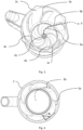
- Fig. 3 depicts the container 1 according to the invention.
- the extension line 5 which is shown as a broken line begins in the central portion 4b of the container bottom 4. It then extends to the peripheral portion 4c of the container bottom 4 in a substantially curved manner. The curve is of a spiral form. This is the bottom part 5a of the extension line 5 and is generally parallel to the bottom 4.
- the extension line 5 bends at nearly the right angle and continues on the container wall 3.
- the extension line 5 is a bent line, i.e. polyline.
- the flow affecting means 4a (flow breaker) of the bottom 4 follows the bottom part 5a of the extension line 5 whereas the flow affecting means 3a (flow breaker) of the wall 3 follows the wall part 5b of the extension line 5.
- the wall part 5b of the extension line 5 is also curved. The curve is of a spiral form.
- the bottom part 5a and the wall part 5b of the extension line 5 form a continuous curved line. In this case the flow affecting means 3a of the wall 3 doesn't immediately follow the flow affecting means 4a of the bottom 4 but begins at some height from the bottom 4 of the container 1.
- Fig. 4 depicts a top view of a horizontal cross-section of the wall 3 of the container 1 of the embodiment according to Fig. 3 .
- the wall part 5b of the extension line 5 extends in a curved manner.
- the food processing tool for instance a knife with blades of Fig. 2 , rotates in a clockwise direction.
- the flow affecting means 3a flow breaker
- the cross-section of the container 1 is circular.
Landscapes
- Engineering & Computer Science (AREA)
- Mechanical Engineering (AREA)
- Food Science & Technology (AREA)
- Food-Manufacturing Devices (AREA)
Description
- The present invention relates to a kitchen appliance, more particularly to a container for a kitchen appliance and a kitchen appliance comprising such a container.
- In conventional kitchen appliances for processing food such as blenders, compact food processors, juicers, stand mixers, choppers, hand blenders which include a container, it is known to modify the geometries of the container to disrupt (break) the laminar flow of the foodstuff (i.e. introducing turbulence and swirling effect) during the processing operation. Such disruption improves the process and results in a more uniform mixing, blending or chopping of the food. Such modifications to the geometry of the container include inward protrusions, such as ribs, ridges and the like.
-
WO 03/001954 A1 - However, many of these protrusions or in general term flow affecting means don't provide for a satisfactory processing of the food. They are either too small, too big or of improper geometric design. Consequently, the food is not processed well and/or cleaning of the container is not convenient and effective. Last but not least, the appearance of the container is not too appealing.
- It is an object of the present invention to overcome the above-mentioned shortcomings of the prior art and to improve functionality and usability of a container for a kitchen appliance or the kitchen appliance in general. Thereby, the ornamental appearance of the container should also be improved.
- The object is achieved by a container according to the features of
claim 1. Advantageous embodiments that can be implemented by themselves or in combination are described in dependent claims. - The invention relates to a container for a kitchen appliance comprising:
- a food processing tool,
- a wall and
- a bottom,
- wherein the wall and the bottom comprise flow affecting means, wherein the flow affecting means of the wall and the flow affecting means of the bottom are configured to communicate so that both flow affecting means follow an extension line comprising a bottom part and a wall part and running from a central portion of the bottom up the wall of the container,
- wherein the flow affecting means are formed as a protrusion,
- characterized in that the bottom part of the extension line runs in a substantially curved manner, wherein the wall part of the extension line runs in a substantially curved manner.
- The extension line is a continuous bent line.
- The flow affecting means of the wall and the flow affecting means of the bottom following the extension line are preferably not in contact. They are in communication so as to follow the extension line running from the central portion of the bottom up the wall of the container. The extension line includes the bottom part and the wall part.
- The container according to the invention provides the following advantages:
- improved food processing (mixing, chopping, blending, crushing) in comparison to existing containers due to flow affecting means on the bottom and the wall of the container
- improved appearance of the container
- moreover, users get the visual impression that the food is really processed effectively as they can observe it by themselves.
- According to one embodiment not forming part of the invention, the bottom part of the extension line runs in a substantially straight manner. This means the bottom flow affecting means adopts this form by following it.
- The effect is that this affecting means is easier to manufacture as its form is rather basic without compromising the function.
- Specifically, the wall part of the extension line runs in a substantially straight manner. This means the wall flow affecting means adopts this form by following it. The effect is that this flow affecting means is easier to manufacture as its form is rather basic without compromising the function.
- According to the invention, the bottom part of the extension line runs in a substantially curved manner. For the sake of clarity in this application curved actually means curvilinear. This curve is formed spirally or logarithmically. Due to this form aesthetic function of the container is improved. Hence, functionality and appearance work hand in hand.
- According to the invention, the wall part of the extension line runs in a substantially curved manner. The same principles apply as for the bottom part of the extension line. Also in this case the curve is formed spirally or logarithmically. Due to the form aesthetic function of the container is improved. Hence, functionality and appearance work hand in hand.
- Preferably, the flow affecting means extends from the bottom portion to the top portion of the wall. The bottom portion runs from the bottom of the container to a certain height above the bottom. The top portion runs from the top edge of the container to a certain height below the edge. In this manner, substantial surface of the wall is used for affecting flow of the processed foodstuff thereby increasing the efficiency.
- Advantageously, the flow affecting means extends from the central portion to the peripheral portion of the bottom. The central portion runs essentially from the centre of the bottom of the container to a certain radius from the centre. The peripheral portion runs from the outermost area where the bottom and the wall of the container intersect to a certain radius in the direction to the centre. In this way, substantial surface of the bottom is used for affecting flow of the processed foodstuff thereby increasing the efficiency.
- In fact any combinations of arrangement of flow affecting means are possible. The most preferred one is with curved bottom and curved wall affecting means, running from the central portion to the peripheral portion of the bottom and from the bottom portion to the top portion of the wall. It turns out this embodiment is the most effective as far as flow affecting (flow breaking) is concerned. Moreover, the appearance of the container that follows and is based on functionality (geometry) is improved.
- In an advantageous solution, the flow affecting means is arranged on the inner surface of the container. This is where rotation (flow) of the processed food inside of the container, more specifically on the bottom and the wall thereof takes place.
- According to one preferred embodiment, the bottom of the container forms a holding means for the food processing tool. The bottom of the container can serve as the holding means for holding the food processing tool, i.e. knife with blades. Typically, the knife comprises 4 or 6 blades.
- Advantageously, the holding means is configured to be detachable. This means it can be cleaned more easily.
- In a preferred embodiment, the flow affecting means is formed as a protrusion protruding from the bottom of the container and from the inner surface of its wall. The protrusion can take a form of a rib, ridge or the like. Preferably, the protrusion is triangular in cross-section. However, other forms as rectangular, square are possible as well.
- Specifically, an angle (α) of the protrusion to the surface of the wall and/or to the surface of the bottom is 15-120°, more preferably 30-90°. The angle defines a rate or efficiency of disrupting the flow of the processed food. It should not be too small in order to preserve good cleaning properties.
- The number of protrusions is optional. Protrusions bring about turbulence pulses in the rotational flow of the processed foodstuff. However, higher number doesn't necessarily mean better processing. Optimal number is chosen experimentally or based on experience.
- According to one embodiment, the container is made of glass material. Glass as material is still perceived by the users as a high grade material. It's food-grade, in other words food-safe.
- Moreover, it has several advantages in terms of appearance.
- In an advantageous solution, the container is made of plastic material. Plastic material is ubiquitous and therefore cheap. Some of plastic materials can have very good food-grade and mechanical properties (e.g. Tritan).
- The horizontal cross-section of the container can be circular or rectangular (square). The preferred option is circular as it proves to be more useful.
- A second aspect of the invention is a kitchen appliance comprising the container according to
claim 1 and the dependent claims. -
-
Fig. 1 is a side view of a kitchen appliance (blender) -
Fig. 2 is a isometric view of the container with straight extension line -
Fig. 3 is a isometric view of the container with curved extension line -
Fig. 4 is a section view of the container with angle of protrusion -
Fig. 1 depicts a container of a kitchen appliance of prior art, more specifically a blender. - The
container 1 is covered by a lid and equipped with a handle. A bottom part of thecontainer 1 comprises a clutch that can be coupled to an output shaft of an electrical motor which is arranged in a blender base (not shown). As seen from the figure, the container wall is provided with two flow affecting means (flow breakers). -
Fig. 2 shows thecontainer 1 according to one embodiment not forming part of the invention. Theextension line 5 which is shown as a broken line begins in thecentral portion 4b of thecontainer bottom 4. It then extends to theperipheral portion 4c of thecontainer bottom 4 in a substantially straight manner. This is thebottom part 5a of theextension line 5 and is generally parallel to thebottom 4. At the end of theperipheral portion 4c of the bottom 4 where thewall 3 begins to rise in itsbottom portion 3b from thebottom 4 of thecontainer 1 in an essentially perpendicular manner theextension line 5 bends at nearly the right angle and continues on thecontainer wall 3. This is thewall part 5b of theextension line 5 also extending in a substantially straight manner and ending in thetop portion 3c of thewall 3 near the edge of thecontainer 1 and being generally parallel to thewall 3. Hence, theextension line 5 is a bent line, i.e. a polyline. The flow affecting means 4a (flow breaker) of thebottom 4 follows thebottom part 5a of theextension line 5 whereas the flow affecting means 3a (flow breaker) of thewall 3 follows thewall part 5b of theextension line 5. In this case the flow affecting means 3a of thewall 3 immediately follows the flow affecting means 4a of thebottom 4 of thecontainer 1. The cross-section of thecontainer 1 is circular. -
Fig. 3 depicts thecontainer 1 according to the invention. Again, theextension line 5 which is shown as a broken line begins in thecentral portion 4b of thecontainer bottom 4. It then extends to theperipheral portion 4c of thecontainer bottom 4 in a substantially curved manner. The curve is of a spiral form. This is thebottom part 5a of theextension line 5 and is generally parallel to thebottom 4. At the end of theperipheral portion 4c of the bottom 4 where thewall 3 begins to rise in itsbottom portion 3b from thebottom 4 of thecontainer 1 in an essentially perpendicular manner theextension line 5 bends at nearly the right angle and continues on thecontainer wall 3. This is thewall part 5b of theextension line 5 ending in thetop portion 3c of thewall 3 near the edge of thecontainer 1 and being generally parallel to thewall 3. Hence, theextension line 5 is a bent line, i.e. polyline. The flow affecting means 4a (flow breaker) of thebottom 4 follows thebottom part 5a of theextension line 5 whereas the flow affecting means 3a (flow breaker) of thewall 3 follows thewall part 5b of theextension line 5. Because the view of thecontainer 1 is isometric it seems like thewall part 5b of theextension line 5 is straight. However, as it can be seen in the section view ofFig. 4 this doesn't hold true. Thewall part 5b of theextension line 5 is also curved. The curve is of a spiral form. Thebottom part 5a and thewall part 5b of theextension line 5 form a continuous curved line. In this case the flow affecting means 3a of thewall 3 doesn't immediately follow the flow affecting means 4a of the bottom 4 but begins at some height from thebottom 4 of thecontainer 1. -
Fig. 4 depicts a top view of a horizontal cross-section of thewall 3 of thecontainer 1 of the embodiment according toFig. 3 . As it can be seen, also thewall part 5b of theextension line 5 extends in a curved manner. The food processing tool, for instance a knife with blades ofFig. 2 , rotates in a clockwise direction. Upon contact with the flow affecting means 3a (flow breaker) the flow is disrupted. This brings about turbulence and swirling thereof and improves blending. The cross-section of thecontainer 1 is circular. -
- 1 container
- 2 food processing tool
- 3 wall
- 3a flow affecting means of a wall
- 3b bottom portion
- 3c top portion
- 4a flow affecting means of a bottom
- 4b central portion
- 4c peripheral portion
- 5 extension line
- 5a bottom part of extension line
- 5b wall part of extension line
- α angle of protrusion
Claims (10)
- A container (1) for a kitchen appliance comprising:- a food processing tool (2),- a wall (3) and- a bottom (4),wherein the wall (3) and the bottom (4) comprise flow affecting means (3a, 4a), wherein the flow affecting means (3a) of the wall (3) and the flow affecting means (4a) of the bottom (4) are configured to communicate so that both flow affecting means (3a, 4a) follow an extension line (5) comprising a bottom part (5a) and a wall part (5b) and running from a central portion (4b) of the bottom (4) up the wall (3) of the container (1), wherein the flow affecting means (4a) is formed as a protrusion,characterised in thatthe bottom part (5a) of the extension line (5) runs in a substantially curved manner, wherein the wall part (5b) of the extension line (5) runs in a substantially curved manner.
- Container (1) according to any of the preceding claims, wherein the flow affecting means (3a) extends from the bottom portion (3b) to the top portion (3c) of the wall (3).
- Container (1) according to any of the preceding claims, wherein the flow affecting means (3a) is arranged on the inner surface of the container (1).
- Container (1) according to any of the preceding claims, wherein the bottom (4) of the container (1) forms a holding means for the food processing tool (2).
- Container (1) according to claim 4, wherein the holding means is configured to be detachable.
- Container according to claim 5, wherein an angle (α) of the protrusion to the surface of the wall (3) and/or the surface of the bottom (4) is 15-120°.
- Container according to claim 6, wherein the angle (α) is preferably 30-90°.
- Container (1) according to any of the preceding claims, wherein the container (1) is made of glass material.
- Container (1) according to any of claims 1-7, wherein the container (1) is made of plastic material.
- Kitchen appliance comprising the container (1) according to any of the preceding claims.
Priority Applications (2)
| Application Number | Priority Date | Filing Date | Title |
|---|---|---|---|
| EP19187298.5A EP3766394B1 (en) | 2019-07-19 | 2019-07-19 | Container for a kitchen appliance |
| CN202010691703.9A CN112237391B (en) | 2019-07-19 | 2020-07-17 | Containers for kitchen utensils |
Applications Claiming Priority (1)
| Application Number | Priority Date | Filing Date | Title |
|---|---|---|---|
| EP19187298.5A EP3766394B1 (en) | 2019-07-19 | 2019-07-19 | Container for a kitchen appliance |
Publications (3)
| Publication Number | Publication Date |
|---|---|
| EP3766394A1 EP3766394A1 (en) | 2021-01-20 |
| EP3766394B1 true EP3766394B1 (en) | 2024-12-11 |
| EP3766394C0 EP3766394C0 (en) | 2024-12-11 |
Family
ID=67438173
Family Applications (1)
| Application Number | Title | Priority Date | Filing Date |
|---|---|---|---|
| EP19187298.5A Active EP3766394B1 (en) | 2019-07-19 | 2019-07-19 | Container for a kitchen appliance |
Country Status (2)
| Country | Link |
|---|---|
| EP (1) | EP3766394B1 (en) |
| CN (1) | CN112237391B (en) |
Families Citing this family (1)
| Publication number | Priority date | Publication date | Assignee | Title |
|---|---|---|---|---|
| CN113998311B (en) | 2017-07-18 | 2024-03-15 | 布利克斯有限公司 | Container, container content processor, container content processing system and method |
Family Cites Families (21)
| Publication number | Priority date | Publication date | Assignee | Title |
|---|---|---|---|---|
| US6431744B1 (en) * | 1999-11-18 | 2002-08-13 | Fred L. Ash | Blender hopper |
| DE10016297A1 (en) * | 2000-03-31 | 2001-10-04 | Bsh Bosch Siemens Hausgeraete | Strainer attachment for food processor has two or more straining blades on hub provided with rib protrusions on side facing sieve and with cutting edges at trailing end |
| CA2450764C (en) * | 2001-06-26 | 2013-12-10 | Vita-Mix Corporation | Container for a blender |
| GB2398733B (en) * | 2003-02-28 | 2005-03-23 | Richards Morphy N I Ltd | Improved food blending vessel |
| US7422361B2 (en) * | 2005-02-04 | 2008-09-09 | Hamilton Beach Brands, Inc. | Dispensing blender |
| US7918601B2 (en) * | 2005-02-04 | 2011-04-05 | Hamilton Beach Brands, Inc. | Dispensing blender jar |
| US20070076683A1 (en) * | 2005-09-30 | 2007-04-05 | Chung Ching A | Low power module for a station of a wireless communication system and related method |
| FR2962319B1 (en) * | 2010-07-09 | 2012-08-10 | Seb Sa | WORK CONTAINER COMPRISING A REMOVABLE BASE AND CULINARY PREPARATION ELECTRICAL EQUIPMENT EQUIPPED WITH SUCH A CONTAINER |
| FR2968916B1 (en) * | 2010-12-17 | 2013-02-15 | Seb Sa | FOOD COOKING APPARATUS WITH WILDLIFE BLADE |
| EP2486833B8 (en) * | 2011-02-10 | 2018-08-15 | Main Power InnoTech (Shenzhen) Manufacturing Co. Ltd. | Mixing vessel |
| US8550695B2 (en) * | 2011-09-23 | 2013-10-08 | Whirlpool Corporation | Blender with varying internally and externally shaped container |
| US9370280B2 (en) * | 2011-09-23 | 2016-06-21 | Whirlpool Corporation | Blender with varying internally and externally shaped container |
| JP3179398U (en) * | 2012-08-20 | 2012-11-01 | 株式会社曙産業 | Household stirring container |
| US20140151479A1 (en) * | 2012-11-30 | 2014-06-05 | Te-Sheng Wu | Food Heating Device |
| CN203802160U (en) * | 2014-02-25 | 2014-09-03 | 李文钦 | Internal structure of cup body |
| CN107427160A (en) * | 2015-02-11 | 2017-12-01 | 沙克忍者运营有限责任公司 | Agitator system with vast capacity tank |
| CN107847085B (en) * | 2015-07-10 | 2021-06-15 | Bsh家用电器有限公司 | An insert for kitchen equipment |
| CN107028473A (en) * | 2016-02-04 | 2017-08-11 | 漳州灿坤实业有限公司 | Fruit juice mixer container and fruit juice mixer |
| CN108324132B (en) * | 2017-01-20 | 2022-02-01 | 广东美的生活电器制造有限公司 | Food processor with stirring function |
| CN208228873U (en) * | 2017-09-04 | 2018-12-14 | 广东美的生活电器制造有限公司 | Stir cup assembly and cooking machine |
| CN209091003U (en) * | 2018-06-08 | 2019-07-12 | 九阳股份有限公司 | A kind of simple food processor of structure |
-
2019
- 2019-07-19 EP EP19187298.5A patent/EP3766394B1/en active Active
-
2020
- 2020-07-17 CN CN202010691703.9A patent/CN112237391B/en active Active
Also Published As
| Publication number | Publication date |
|---|---|
| EP3766394A1 (en) | 2021-01-20 |
| CN112237391B (en) | 2024-02-13 |
| EP3766394C0 (en) | 2024-12-11 |
| CN112237391A (en) | 2021-01-19 |
Similar Documents
| Publication | Publication Date | Title |
|---|---|---|
| US8122821B2 (en) | Food-processing device | |
| US9370280B2 (en) | Blender with varying internally and externally shaped container | |
| EP2572614B1 (en) | Blender with varying internally and externally shaped container | |
| US8550695B2 (en) | Blender with varying internally and externally shaped container | |
| EP2645906B1 (en) | Hand held masher device | |
| US20050122837A1 (en) | Blender jar | |
| US12336668B2 (en) | Blending system | |
| EP2451321B1 (en) | Kitchen appliance | |
| US6193181B1 (en) | Electrical household appliance for cooking preparation, such as multipurpose domestic robot, and multipurpose working container | |
| US20120031285A1 (en) | Kitchen appliance | |
| EP3766394A1 (en) | Container for a kitchen appliance | |
| RU2662389C2 (en) | Tool for a kitchen appliance with a facing coating | |
| US3335772A (en) | Comminuting attachment for hand mixer | |
| US12102266B2 (en) | Appliance for processing foods | |
| CN203802323U (en) | Kitchen utensil with base provided with handle and packaged motor | |
| KR100271470B1 (en) | Mixer | |
| KR200474168Y1 (en) | Polygon blender | |
| EP2767203B1 (en) | Hand blender | |
| CN219331429U (en) | Cooking utensil | |
| CN105682518B (en) | Tools with separating ribs for kitchen utensils | |
| CN219745034U (en) | Vertical double-gear meat grinder | |
| US20260102025A1 (en) | Chamfered blending jar with elongate ridges | |
| RU2775495C1 (en) | Appliance for food processing | |
| CN211961839U (en) | Household appliance for processing food | |
| JP2024010865A (en) | cooking cup |
Legal Events
| Date | Code | Title | Description |
|---|---|---|---|
| PUAI | Public reference made under article 153(3) epc to a published international application that has entered the european phase |
Free format text: ORIGINAL CODE: 0009012 |
|
| STAA | Information on the status of an ep patent application or granted ep patent |
Free format text: STATUS: THE APPLICATION HAS BEEN PUBLISHED |
|
| AK | Designated contracting states |
Kind code of ref document: A1 Designated state(s): AL AT BE BG CH CY CZ DE DK EE ES FI FR GB GR HR HU IE IS IT LI LT LU LV MC MK MT NL NO PL PT RO RS SE SI SK SM TR |
|
| AX | Request for extension of the european patent |
Extension state: BA ME |
|
| STAA | Information on the status of an ep patent application or granted ep patent |
Free format text: STATUS: REQUEST FOR EXAMINATION WAS MADE |
|
| 17P | Request for examination filed |
Effective date: 20210720 |
|
| RBV | Designated contracting states (corrected) |
Designated state(s): AL AT BE BG CH CY CZ DE DK EE ES FI FR GB GR HR HU IE IS IT LI LT LU LV MC MK MT NL NO PL PT RO RS SE SI SK SM TR |
|
| STAA | Information on the status of an ep patent application or granted ep patent |
Free format text: STATUS: EXAMINATION IS IN PROGRESS |
|
| 17Q | First examination report despatched |
Effective date: 20230104 |
|
| GRAP | Despatch of communication of intention to grant a patent |
Free format text: ORIGINAL CODE: EPIDOSNIGR1 |
|
| STAA | Information on the status of an ep patent application or granted ep patent |
Free format text: STATUS: GRANT OF PATENT IS INTENDED |
|
| INTG | Intention to grant announced |
Effective date: 20240807 |
|
| GRAS | Grant fee paid |
Free format text: ORIGINAL CODE: EPIDOSNIGR3 |
|
| GRAA | (expected) grant |
Free format text: ORIGINAL CODE: 0009210 |
|
| STAA | Information on the status of an ep patent application or granted ep patent |
Free format text: STATUS: THE PATENT HAS BEEN GRANTED |
|
| AK | Designated contracting states |
Kind code of ref document: B1 Designated state(s): AL AT BE BG CH CY CZ DE DK EE ES FI FR GB GR HR HU IE IS IT LI LT LU LV MC MK MT NL NO PL PT RO RS SE SI SK SM TR |
|
| REG | Reference to a national code |
Ref country code: GB Ref legal event code: FG4D |
|
| REG | Reference to a national code |
Ref country code: CH Ref legal event code: EP |
|
| REG | Reference to a national code |
Ref country code: DE Ref legal event code: R096 Ref document number: 602019063300 Country of ref document: DE |
|
| REG | Reference to a national code |
Ref country code: IE Ref legal event code: FG4D |
|
| U01 | Request for unitary effect filed |
Effective date: 20250110 |
|
| U07 | Unitary effect registered |
Designated state(s): AT BE BG DE DK EE FI FR IT LT LU LV MT NL PT RO SE SI Effective date: 20250117 |
|
| PG25 | Lapsed in a contracting state [announced via postgrant information from national office to epo] |
Ref country code: HR Free format text: LAPSE BECAUSE OF FAILURE TO SUBMIT A TRANSLATION OF THE DESCRIPTION OR TO PAY THE FEE WITHIN THE PRESCRIBED TIME-LIMIT Effective date: 20241211 |
|
| PG25 | Lapsed in a contracting state [announced via postgrant information from national office to epo] |
Ref country code: ES Free format text: LAPSE BECAUSE OF FAILURE TO SUBMIT A TRANSLATION OF THE DESCRIPTION OR TO PAY THE FEE WITHIN THE PRESCRIBED TIME-LIMIT Effective date: 20241211 |
|
| PG25 | Lapsed in a contracting state [announced via postgrant information from national office to epo] |
Ref country code: NO Free format text: LAPSE BECAUSE OF FAILURE TO SUBMIT A TRANSLATION OF THE DESCRIPTION OR TO PAY THE FEE WITHIN THE PRESCRIBED TIME-LIMIT Effective date: 20250311 |
|
| PG25 | Lapsed in a contracting state [announced via postgrant information from national office to epo] |
Ref country code: GR Free format text: LAPSE BECAUSE OF FAILURE TO SUBMIT A TRANSLATION OF THE DESCRIPTION OR TO PAY THE FEE WITHIN THE PRESCRIBED TIME-LIMIT Effective date: 20250312 |
|
| PG25 | Lapsed in a contracting state [announced via postgrant information from national office to epo] |
Ref country code: RS Free format text: LAPSE BECAUSE OF FAILURE TO SUBMIT A TRANSLATION OF THE DESCRIPTION OR TO PAY THE FEE WITHIN THE PRESCRIBED TIME-LIMIT Effective date: 20250311 |
|
| PG25 | Lapsed in a contracting state [announced via postgrant information from national office to epo] |
Ref country code: SM Free format text: LAPSE BECAUSE OF FAILURE TO SUBMIT A TRANSLATION OF THE DESCRIPTION OR TO PAY THE FEE WITHIN THE PRESCRIBED TIME-LIMIT Effective date: 20241211 |
|
| PG25 | Lapsed in a contracting state [announced via postgrant information from national office to epo] |
Ref country code: PL Free format text: LAPSE BECAUSE OF FAILURE TO SUBMIT A TRANSLATION OF THE DESCRIPTION OR TO PAY THE FEE WITHIN THE PRESCRIBED TIME-LIMIT Effective date: 20241211 |
|
| PG25 | Lapsed in a contracting state [announced via postgrant information from national office to epo] |
Ref country code: IS Free format text: LAPSE BECAUSE OF FAILURE TO SUBMIT A TRANSLATION OF THE DESCRIPTION OR TO PAY THE FEE WITHIN THE PRESCRIBED TIME-LIMIT Effective date: 20250411 |
|
| PG25 | Lapsed in a contracting state [announced via postgrant information from national office to epo] |
Ref country code: SK Free format text: LAPSE BECAUSE OF FAILURE TO SUBMIT A TRANSLATION OF THE DESCRIPTION OR TO PAY THE FEE WITHIN THE PRESCRIBED TIME-LIMIT Effective date: 20241211 |
|
| PG25 | Lapsed in a contracting state [announced via postgrant information from national office to epo] |
Ref country code: CZ Free format text: LAPSE BECAUSE OF FAILURE TO SUBMIT A TRANSLATION OF THE DESCRIPTION OR TO PAY THE FEE WITHIN THE PRESCRIBED TIME-LIMIT Effective date: 20241211 |
|
| U20 | Renewal fee for the european patent with unitary effect paid |
Year of fee payment: 7 Effective date: 20250731 |
|
| PLBE | No opposition filed within time limit |
Free format text: ORIGINAL CODE: 0009261 |
|
| STAA | Information on the status of an ep patent application or granted ep patent |
Free format text: STATUS: NO OPPOSITION FILED WITHIN TIME LIMIT |
|
| REG | Reference to a national code |
Ref country code: CH Ref legal event code: L10 Free format text: ST27 STATUS EVENT CODE: U-0-0-L10-L00 (AS PROVIDED BY THE NATIONAL OFFICE) Effective date: 20251022 |
|
| 26N | No opposition filed |
Effective date: 20250912 |
|
| REG | Reference to a national code |
Ref country code: CH Ref legal event code: H13 Free format text: ST27 STATUS EVENT CODE: U-0-0-H10-H13 (AS PROVIDED BY THE NATIONAL OFFICE) Effective date: 20260224 |
|
| GBPC | Gb: european patent ceased through non-payment of renewal fee |
Effective date: 20250719 |
|
| PG25 | Lapsed in a contracting state [announced via postgrant information from national office to epo] |
Ref country code: GB Free format text: LAPSE BECAUSE OF NON-PAYMENT OF DUE FEES Effective date: 20250719 |
|
| PG25 | Lapsed in a contracting state [announced via postgrant information from national office to epo] |
Ref country code: CH Free format text: LAPSE BECAUSE OF NON-PAYMENT OF DUE FEES Effective date: 20250731 |