EP3766371A1 - Stopper and slide fastener comprising same - Google Patents
Stopper and slide fastener comprising same Download PDFInfo
- Publication number
- EP3766371A1 EP3766371A1 EP18910224.7A EP18910224A EP3766371A1 EP 3766371 A1 EP3766371 A1 EP 3766371A1 EP 18910224 A EP18910224 A EP 18910224A EP 3766371 A1 EP3766371 A1 EP 3766371A1
- Authority
- EP
- European Patent Office
- Prior art keywords
- base
- insert
- bases
- slider
- housing
- Prior art date
- Legal status (The legal status is an assumption and is not a legal conclusion. Google has not performed a legal analysis and makes no representation as to the accuracy of the status listed.)
- Pending
Links
Images









Classifications
-
- A—HUMAN NECESSITIES
- A44—HABERDASHERY; JEWELLERY
- A44B—BUTTONS, PINS, BUCKLES, SLIDE FASTENERS, OR THE LIKE
- A44B19/00—Slide fasteners
- A44B19/24—Details
- A44B19/26—Sliders
- A44B19/30—Sliders with means for locking in position
- A44B19/303—Self-locking sliders, e.g. slider body provided with locking projection or groove, friction means
-
- A—HUMAN NECESSITIES
- A44—HABERDASHERY; JEWELLERY
- A44B—BUTTONS, PINS, BUCKLES, SLIDE FASTENERS, OR THE LIKE
- A44B19/00—Slide fasteners
- A44B19/24—Details
- A44B19/26—Sliders
-
- A—HUMAN NECESSITIES
- A44—HABERDASHERY; JEWELLERY
- A44B—BUTTONS, PINS, BUCKLES, SLIDE FASTENERS, OR THE LIKE
- A44B19/00—Slide fasteners
- A44B19/24—Details
- A44B19/38—Means at the end of stringer by which the slider can be freed from one stringer, e.g. stringers can be completely separated from each other
-
- A—HUMAN NECESSITIES
- A44—HABERDASHERY; JEWELLERY
- A44B—BUTTONS, PINS, BUCKLES, SLIDE FASTENERS, OR THE LIKE
- A44B19/00—Slide fasteners
- A44B19/24—Details
- A44B19/36—Means for permanently uniting the stringers at the end; Means for stopping movement of slider at the end
-
- A—HUMAN NECESSITIES
- A44—HABERDASHERY; JEWELLERY
- A44B—BUTTONS, PINS, BUCKLES, SLIDE FASTENERS, OR THE LIKE
- A44B19/00—Slide fasteners
- A44B19/24—Details
- A44B19/38—Means at the end of stringer by which the slider can be freed from one stringer, e.g. stringers can be completely separated from each other
- A44B19/384—Separable slide fasteners with quick opening devices
-
- A—HUMAN NECESSITIES
- A44—HABERDASHERY; JEWELLERY
- A44D—INDEXING SCHEME RELATING TO BUTTONS, PINS, BUCKLES OR SLIDE FASTENERS, AND TO JEWELLERY, BRACELETS OR OTHER PERSONAL ADORNMENTS
- A44D2203/00—Fastening by use of magnets
Definitions
- the present disclosure is related to a stop member and a slide fastener including the same.
- Patent literatures 1 and 2 disclose a separable stop for slide fastener with magnets embedded therein.
- Patent literature 1 discloses a support member 7 provided with a groove portion 15, and an insertion member 8 having a protruded portion 20 to be inserted into the groove portion 15.
- the groove portion 15 is provided with a magnet or magnetic body.
- the protruded portion 20 is provided with a magnet or magnetic body therein. The protruded portion 20 and the groove portion 15 are magnetically attracted each another, and the protruded portion 20 is automatically inserted into the groove portion 15 (See para. 0037 of Patent literature 1).
- Patent literature 2 discloses a method of attaching a magnet shown in its Figs. 5 and 6 .
- the present inventors have newly identified a technical problem that, in the case of Patent literature 1 or 2, it may take time for inserting an insertion plate of the insertion member into a space between top and bottom flanges of slider.
- Stop member includes: a first member including a first insert to be inserted into a slider via a rear mouth of the slider, and a first base positioned rearward of the first insert; and a second member including a second insert to be inserted into the slider via a slit extending between the rear mouth and a front mouth of the slider, and a second base to be overlaid onto the first base.
- the first and second bases are configured to effect magnetic attraction and/or repulsion between the first and second bases, when the first and second bases are overlaid.
- the second base rotates relative to the first base in accordance with the magnetic attraction and/or repulsion to allow the second insert to pivot toward the slit.
- the second base starts to rotate relative to the first base in accordance with magnetic attraction between the first and second bases.
- the second base starts to rotate relative to the first base in accordance with magnetic repulsion between the first and second bases.
- the first and second bases are configured to effect magnetic attraction between the first and second bases when the first and second bases are overlaid.
- the second base rotates relative to the first base in a process of magnetic attachment of the first and second bases in accordance with the magnetic attraction.
- the second base moves closer to the first base in an axial direction of a rotational axis regarding the pivoting of the second insert and accordingly, the second insert pivots about the rotational axis.
- At least one of the first and second bases is provided with a permanent magnet.
- the permanent magnet has first and second poles arranged along a rotational axis regarding the pivoting of the second insert.
- the first and second bases are configured to effect magnetic repulsion when the first and second bases are overlaid, and the second base rotates relative to the first base in accordance with the magnetic repulsion.
- the first and second bases are respectively provided with first and second permanent magnets.
- each of the first and second permanent magnets has first and second poles arranged in a plane crossing or orthogonal to a rotational axis AX regarding the pivoting of the second insert.
- the first and second bases are engageable in a rotatable manner.
- the permanent magnet is housed in a housing of the first or second base.
- one of the first and second bases includes a sloped surface that extends about a rotational axis regarding the pivoting of the second insert and the other one of the first and second bases includes a sliding portion that slides on the sloped surface.
- one of the first base and the second base is provided with an axial portion and the other one of the first base and the second base is provided with a receiving portion that receives the axial portion.
- the first base is provided with the axial portion, the first base has a first housing for housing a first permanent magnet, and the first housing has a bottom positioned in the proximity of an end of the axial portion.
- the second base is provided with the receiving portion, the second base has a second housing for housing a second permanent magnet, and the second housing has a bottom positioned in the proximity of a bottom of the receiving portion.
- a stop member includes: a first member including a first insert to be inserted into a slider via a rear mouth of the slider and a first base positioned rearward of the first insert; and a second member including a second insert to be inserted into the slider via a slit extending between the rear mouth and a front mouth of the slider and a second base to be overlaid onto the first base.
- the first and second bases are configured to effect magnetic attraction and/or repulsion between the first and second bases when the first and second bases are overlaid.
- One of the first and second bases includes a sloped surface that extends about a rotational axis AX regarding the pivoting of the second insert and the other one of the first and second bases includes a sliding portion that slides on the sloped surface.
- the sloped surface is provided to convert displacement of the second base in an axial direction of the rotational axis to displacement of the second base about the rotational axis.
- Slide fastener according to an aspect of the present disclosure has the above-described stop member.
- stop member may be provided with improved operability.
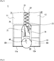
- Fig. 1 is a schematic elevational view of a rear end of a slide fastener 1 provided with a stop member 50 according to an aspect of the present disclosure.
- First and second fastener stringers 31,32 are closed, and illustration of slider 40 (See Figs. 2 and 3 ) positioned frontward of the stop member 50 of the slide fastener 1 is omitted.
- Fig. 2 is a schematic perspective view of a non-limiting exemplary slider 40 included in the slide fastener 1.
- Fig. 3 is a schematic side view of a non-limiting exemplary slider 40 included in the slide fastener 1.
- Slide fastener 1 has first and second fastener stringers 31,32 and a slider 40 for opening and closing the first and second fastener stringers 31,32.
- the first fastener stringer 31 has a first fastener tape 11 and first fastener elements 21 provided on the side-edge, extending in the lengthwise direction, of the first fastener tape 11.
- the second fastener stringer 32 has a second fastener tape 12, and second fastener elements 22 provided on a side-edge, extending in the lengthwise direction, of the second fastener tape 12.
- Fastener tape 11,12 may be a fabric such as woven fabric or knitted fabric or combination thereof.
- the fastener tape 11,12 has a pair of tape surfaces which define a thickness of the fastener tape.
- the fastener element 21,22 may be a resin element, metal element, coil element or other types of element.
- the side-edge of the first fastener tape 11 with the first fastener element 21 and the side-edge of the second fastener tape 12 with the second fastener element 22 are arranged to face one another, and thus may be referred to as opposed side-edges.
- Frontward movement of slider 40 closes the first and second fastener stringers 31,32.
- Rearward movement of slider 40 opens the first and second fastener stringers 31,32.
- "Front-and-Rear direction” is determined based on a direction of movement of slider 40.
- the first and second fastener stringers 31,32 are arranged in Left-and-Right direction that is orthogonal to the Front-and-Rear direction.
- the first and second fastener stringers 31,32 can be thus referred to as left and right fastener stringers. This holds true for the fastener tapes 11,12 and the fastener elements 21,22.
- Left-and-Right direction is a direction orthogonal to the Front-and-Rear direction and parallel to a tape surface of respective fastener tapes 11,12.
- Up-and-Down direction is orthogonal to Front-and-Rear direction and Left-and-Right direction.
- Up-and-Down direction matches a direction an interconnecting post 43 (described below) of the slider 40 extends. Redefining the Font-and-Rear direction, Left-and-Right direction, and Up-and-Down direction would be possible based on other descriptions in the present specification.
- the slider 40 has a top wing 41, a bottom wing 42, and an interconnecting post 43 that interconnects the top wing 41 and the bottom wing 42.
- Paired left and right front mouths 44 are arranged to sandwich the interconnecting post 43.
- Rear mouth 45 is arranged at the opposite side relative to the front mouth 44 in the front-and-rear direction.
- Left slit (or tape-passage) 46 allowing the first fastener tape 11 to move there-though, extends between the left-side front mouth 44 and the rear mouth 45.
- Right slit 46 allowing the second fastener tape 12 to move there-through, extends between the right-side front mouth 44 and the rear mouth 45.
- the slider 40 has Y-shaped element-passage bifurcated by the interconnecting post 43 between the top wing 41 and the bottom wing 42.
- First fastener elements 21 enter in and go out from the slider 40 via the left-side front mouth 44.
- Second fastener elements 22 enter in and go out from the slider 40 via the right-side front mouth 44.
- Engaged first and second fastener elements 21,22 enter in and go out from the slider 40 via the rear mouth 45.
- Top wing 41 of the slider 40 includes a top wing plate 41a and paired top flanges 41b protruded downward at the left and right side-edges of the top wing plate 41a.
- Bottom wing 42 includes a bottom wing plate 42a and paired bottom flanges 42b protruded upward at the left and right side-edges of the bottom wing plate 42a. In some cases, one of the top and bottom flanges 41b and 42b is omitted.
- the top wing plate 41a and the bottom wing plate 42a may be arranged in a plane orthogonal to Up-and-Down direction along which the interconnecting post 43 extends.
- the slider 40 has a pull-attachment column 48 and a pull tab 49 attached to the top wing plate 41a via the pull-attachment column 48.
- the slider 40 has a locking pawl 47 to be operated by the pull tab 49.
- the slider 40 may be made of metal, resin or other material.
- Slide fastener 1 has a stop member 50 additionally to the above-described first and second fastener stringers 31,32.
- the stop member 50 defines a stop position for the slider 40.
- the stop member 50 of the present disclosure has first and second members 51 and 52 which are separable. Separation of the first and second members 51 and 52 allows separation of the first and second fastener stringers 31,32. Therefore, the stop member 50 may be referred to as a separable stop.
- the first member 51 is secured to the first fastener tape 11 and positioned rearward of the first fastener element 21.
- the second member 52 is secured to the second fastener tape 12 and positioned rearward of the second fastener element 22.
- the first or second member 51,52 may be arranged to be slightly protruded rearward from the terminal end 11e, 12e of the first or second fastener tape 11,12, not necessarily limited to this though.
- the stop member 50 is provided at the terminal of the fastener stringer 31,32 or of the fastener tape 11,12 or of the fastener elements 21,22 and thus may be referred to as a terminal member.
- each of the first and second members 51 and 52 may be made of resin, metal or other material.
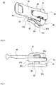
- Fig. 4 is schematic perspective view of the first member 51.
- Fig. 5 is a schematic perspective view of the first member 51, illustrating a structure of the first member at the opposite side compared with Fig. 4 .
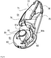
- Fig. 6 is a schematic perspective view of the first member 51 which is viewed obliquely from a different point compared with Fig. 5 .
- Fig. 7 is a schematic perspective view of the second member 52.
- Fig. 8 is a schematic perspective view of the second member 52, illustrating a structure of the second member 52 at the opposite side compared with Fig. 7 .
- Fig. 9 is a schematic cross-sectional view of the stop member taken along a chain line X9-X9 in Fig. 1 .
- the first member 51 has a first insert 71 to be inserted into the slider 40 via the rear mouth 45 of the slider 40 of the slide fastener 1; and a first base 61 positioned rearward of the first insert 71.
- the second member 52 includes a second insert 72 to be inserted into the slider 40 via the slit 46 extending between the rear mouth 45 and the front mouth 44 of the slider 40, and a second base 62 to be overlaid onto the first base 61.
- the first and second bases 61,62 are configured to effect magnetic attraction and/or repulsion (in the case of Fig.9 , magnetic attraction) between the first and second bases 61,62 when the first and second bases 61,62 are overlaid.
- the second base 62 rotates relative to the first base 61 in accordance with the magnetic attraction and/or repulsion to allow the second insert 72 to pivot toward the slit 46. Accordingly, the stop member 50 with improved operability can be provided.
- the first insert 71 extends along the Front-and-Rear direction between the first base 61 and the first fastener elements 21.
- the second insert 72 extends along the Front-and-Rear direction between the second base 62 and the second fastener elements 22.
- the first insert 71 has a groove 73 into which the second insert 72 is inserted.
- the groove 73 extends in the Front-and-Rear direction and is opening at front, rear and right sides.
- the groove 73 receives the second insert 72 which has entered into the slider 40 via the right-side slit 46 of the slider 40 while the first insert 71 has been inserted into the slider 40.
- the second insert 72 is inserted into the groove 73 of the first insert 71 so that upward-and-downward displacement of the second insert 72 is restricted.
- the first member 51 may be configured to facilitate to keep the slider 40 stationary on the first member 51. It is facilitated that the second insert 72 can enter into the slider 40 via the right-side slit 46 of the slider 40 while the first insert 71 has been inserted into the slider 40.
- the first member 51 may have one or any combination of a thin plate 74, a guide 75, and a stopping wall 76.
- Thin plate 74 is arranged adjacent to the first insert 71 in the left-and-right direction.
- Thin plate 74 has a thickness that enables its insertion into the slit 46 of the slider 40.
- Guide 75 is projected from the thin plate 74 in Up-and-Down direction and extends along the Front-and-Rear direction. Embodiments are envisioned where the guide 75 is protruded from the thin plate 74 upward only or downward only.
- Groove 77 is formed between the first insert 71 and the guide 75, and a flange portion of the slider 40 is inserted into the groove 77.
- the first insert 71 is protruded from the thin plate 74 in Up-and-down direction.
- the stopping wall 76 extends in Left-and-Right direction and is coupled to the first insert 71, the thin plate 74, and the guide 75.
- the stopping wall 76 defines a stop position for the slider 40.
- the first base 61 is positioned rearward of the first insert 71, and is directly or indirectly coupled to the first insert 71. Indirect coupling of the first base 61 with the first insert 71 indicates that the first base 61 is coupled with the first insert 71 via another or other structural portion(s) such as the stopping wall 76.
- the first base 61 has a flat plate 63, an axial portion 81, and a sloped surface 83.
- the axial portion 81 is arranged in and protruded downward from the bottom surface the flat plate 63.
- the axial portion 81 has a portion with a diameter reduced toward the end 91.
- the axial portion 81 has an end surface 81a in its end 91, and an outer peripheral surface 81b in the outer periphery of the end surface 81a.
- Flattened end surface 81a reduces a stimulus otherwise given to a human skin by the axial portion 81.
- the sloped surface 83 extends about a rotational axis AX regarding the pivoting of the second insert 72.
- the sloped surface 83 extends in an arc about the rotational axis AX, but embodiments are envisioned where it extends across the entire circle about the rotational axis AX.
- the sloped surface 83 extends between the outer peripheral surface 81b of the axial portion 81 and the bottom surface of the flat plate 63.
- the sloped surface 83 is arranged to convert displacement of the second base 62 in the axial direction of the rotational axis AX to displacement of the second base 62 about the rotational axis AX.
- the second insert 72 of the second member 52 includes a portion which is capable of entering into the slider 40 via the slit 46 of the slider 40.
- the second insert 72 is a flat plate with a thickness enabling the passing via the slit 46 of the slider 40.
- the second insert 72 has a side-edge 72a that touches the top wing 41 or the bottom wing 42 of the slider 40.
- the side-edge 72a of the second insert 72 has a shape that matches a side part of the profile of the top or bottom wing 41 or 42 of the slider 40.
- the side-edge 72a of the second insert 72 has a recess 72b for avoiding interference with a corner 42c of the slider 40.
- the second member 52 has a guide 85 and a third fastener element 23 additionally to the second insert 72.
- the guide 85 is protruded in both sides of upward and downward from the second insert 72, and extends in the Front-and-Rear direction. This guide 85 defines a passage for the slider 40.
- the third fastener element 23 is coupled to the front end of the second insert 72 and is positioned between the second insert 72 and the second fastener element 22. When the second insert 72 is inserted into the slider 40 via the slit 46 which extends between the rear mouth 45 and the front mouth 44 of the slider 40, the third fastener element 23 is positioned adjacent to and frontward of the front mouth 44 of the slider 40. Frontward movement of the slider 40 allows the third fastener element 23 to be inside the slider 40 and, in turn, be engaged with the first fastener element 21 inside the slider 40 (See Fig. 1 ).
- the third fastener element 23 has a groove 24 and the first insert 71 has an insertion portion 25.
- the insertion portion 25 of the first insert 71 is inserted into the groove 24 of the third fastener element 23 (see Fig. 1 ), thus suppressing the front ends of the first and second members 51 52 from being separated in Up-and-Down direction.
- the second base 62 has a receiving portion 82 that receives the axial portion 81 of the first base 61, and a sliding portion 84 that slides on the sloped surface 83 provided in the first base 61.
- the receiving portion 82 has a bottom surface 82a that is opposed to the end surface 81a of the axial portion 81, and an outer peripheral surface 82b that is opposed to the outer peripheral surface 81b of the axial portion 81.
- the bottom surface 82a is a substantially flat surface but should not be limited to this.
- the outer peripheral surface 82b is a slant surface that slants obliquely relative to the bottom surface 82a.
- the sliding portion 84 is arranged to protrude into the internal space of the receiving portion 82.
- the sliding portion 84 is protruded radially inward of the rotational axis AX regarding the pivoting of the second insert 72.
- the sliding portion 84 has a projected part 84a.
- the projected part 84a of the sliding portion 84 is inserted into a recess 81c of the axial portion 81 (See Fig. 6 ).
- the second base 62 is provided with the axial portion 81 and the first base 61 is provided with the receiving portion 82.
- the second base 62 is provided with the sloped surface 83 and the first base 61 is provided with the sliding portion 84.
- the axial portion 81 and the receiving portion 82 are provided for a purpose of positioning when stacking the first and second bases 61 and 62 and/or for a purpose of enhancing a rotational stability of the first and second bases 61 and 62.
- the first and second bases 61,62 are configured to effect magnetic attraction and/or repulsion (magnetic attraction in the case of Fig. 9 ) between the first and second bases 61,62 when the first and second bases 61,62 are overlaid. Furthermore, the second base 62 is rotatable relative to the first base 61 in accordance with the magnetic attraction and/or repulsion to allow the second insert 72 to pivot towards the slit 46. Accordingly, the stop member 50 with improved operability can be provided.
- the magnetic attraction is effected based on the use of at least one permanent magnet.
- the magnetic repulsion is effected based on the use of permanent magnets respectively provided in the first and second bases 61,62.
- the first base 61 has one or more permanent magnets, and the second base 62 has one or more magnetic bodies; (ii) the first base 61 has one or more magnetic bodies, and the second base 62 has one or more permanent magnets; and (iii) the first base 61 has one or more permanent magnets, and the second base 62 has one or more permanent magnets.
- Use of the permanent magnet and the magnetic body can effect the magnetic attraction.
- Use of the permanent magnet and the permanent magnet can effect the magnetic attraction and/or repulsion.
- the permanent magnet has first and second poles as widely known.
- the first pole is one of N-pole and S-pole and the second pole is the other one of N-pole and S-pole.
- the magnetic body can be made of any material magnetically attachable to the permanent magnet and, for example, including one or more metals selected from Iron (Fe), Cobalt (Co), Nickel (Ni), and Gadolinium (Gd).
- Magnetic body can include stainless-steel such as martensite, ferrite, and austenite-ferrite. Note that the stainless-steel is an alloy and, in fact, includes Iron (Fe).
- the permanent magnet and magnetic body can take various shapes such as a bar, circular plate, and ring. Embodiments are envisioned where particulate permanent magnets and magnetic bodies are used.
- the permanent magnet and/or magnetic body can be variously provided in the first base 61 and the second base 62. Embodiments are envisioned where the permanent magnet and/or magnetic body is embedded in the first base 61 through insert-molding or other methods. Embodiments are envisioned where the permanent magnet and/or magnetic body is fitted with or secured, by adhesive, to the first base 61. Embodiments are envisioned where the first base 61 is provided with a housing for hosing the permanent magnet and/or magnetic body. Similar embodiments are envisioned for the second base 62 either.
- the first member 51 (or the first base 61) or the second member 52 (or the second base 62) itself is made of magnetic material.
- the first member 51 or the second member 52 is produced by casting of magnetic metal. Attachment of the first member 51 to the first fastener tape 11 can be achieved by any methods such as sewing and gluing. The same applies to attachment of the second member 52 to the second fastener tape 12.
- the first member 51 is fixed to the first fastener tape 11 as a result of insert-molding using a plastic/resin.
- the second member 52 is fixed to the second fastener tape 12.
- the first base 61 or the second base 62 can additionally have a permanent magnet or magnetic body.
- first base 61 is provided with a first housing 101 for housing the first permanent magnet 111 and the second base 62 is provided with a second housing 102 for housing the second permanent magnet 112.
- first and second permanent magnets 111, 112 with magnetic body can also be understandable. In other words, one can read the following descriptions with replacing one of the first and second permanent magnets 111, 112 with magnetic body.
- Fig. 10 is a schematic bottom view of the first member 51 without illustration of a first cover 121.
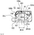
- Fig. 11 is a schematic cross-sectional view of the first member 51 taken along a chain line X11-X11 in Fig. 10 , illustration of a first permanent magnet 111 and the first cover 121 are omitted.
- Fig. 12 is a schematic top view of the second member 52, illustration of a second cover 122 is omitted.
- Fig. 13 is a schematic cross-sectional view of the second member 52 taken along a chain line X13-X13 in Fig. 12 , illustration of a second permanent magnet 112 and the second cover 122 are omitted.
- the first base 61 has the first housing 101 that houses the first permanent magnet 111.
- the first housing 101 is provided to form a hollow in the axial portion 81.
- the first housing 101 has an opening OP101 for introducing the first permanent magnet 111 from the opposite side of the end 91 (e.g. the end surface 81a) of the axial portion 81.
- the first permanent magnet 111 is introduced into the first housing 101 via the opening OP101 of the first housing 101.
- the first housing 101 has a bottom 106 at the side of the end 91 of the axial portion 81.
- the first housing 101 has a circumferential wall surface 101a extending along the depth direction of the first housing 101 and a bottom surface 101b that is crossing or orthogonal to the depth direction of the first housing 101.
- Cross-sectional shape of the first housing 101 in a plane orthogonal to the depth direction of the first housing 101 may take any shape such as a circle, triangle, rectangle and pentagon. It is envisioned that the cross-sectional shape of the first housing 101 changes along the depth direction of the first housing 101. Note that, the depth direction of the first housing 101 matches or is parallel to the axial direction AX1 of the axial portion 81. Note that, the axial direction AX1 of the axial portion 81 is co-axially arranged with the rotational axis AX regarding the pivoting of the second insert 72.
- the bottom 106 of the first housing 101 is positioned in the proximity of the end 91 (e.g. the end surface 81a) of the axial portion 81. Distance between the bottom 106 of the first housing 101 and the end 91 of the axial portion 81 may be reduced, thus increasing magnetic permeability.
- First thinned portion 108 is provided between the end surface 81a of the axial portion 81 and the bottom surface 101b of the first housing 101. It is envisioned that one or more magnetically permeable holes are arranged in the first thinned portion 108 to further facilitate transmission of magnetic field lines there-through.
- the magnetically permeable holes are holes with permeability of magnetic fields and should not be limited to a space.
- the first thinned portion 108 is not necessarily a layer-like portion with a constant thickness.
- the second base 62 has the second housing 102 that houses the second permanent magnet 112.
- the second housing 102 of the second base 62 is provided at the opposite side relative to the receiving portion 82 of the second base 62.
- the second housing 102 has an opening OP102 for introducing the second permanent magnet 112 from the opposite side of the opening of the receiving portion 82.
- the second permanent magnet 112 is introduced into the second housing 102 via the opening OP102 of the second housing 102.
- the second housing 102 has a bottom 107 at the side of the receiving portion 82. Note that, the second housing 102 has a circumferential wall surface 102a extending along the depth direction of the second housing 102 and a bottom surface 102b crossing or orthogonal to the depth direction of the second housing 102.
- Cross-sectional shape of the second housing 102 in a plane orthogonal to the depth direction of the second housing 102 can take any shape such as a circle, triangle, rectangle, and pentagon, for example. It is envisioned that the cross-sectional shape of the second housing 102 changes along the depth direction of the second housing 102. Note that the depth direction of the second housing 102 is opposite to the depth direction of the receiving portion 82.
- the bottom 107 of the second housing 102 is positioned in the proximity of the bottom 92 (e.g. the bottom surface 82a) of the receiving portion 82. Distance between the bottom 107 of the second housing 102 and the bottom 92 of the receiving portion 82 may be reduced, thus increasing magnetic permeability.
- Second thinned portion 109 is provided between the bottom 92 (e.g. the bottom surface 82a) of the receiving portion 82 and the bottom 107 (e.g. the bottom surface 102b) of the second housing 102. It is envisioned that one or more magnetically permeable holes are arranged in the second thinned portion 109 to further facilitate transmission of magnetic field lines there-through.
- the magnetically permeable holes are holes with permeability for magnetic fields lines and should not be limited to a space.
- the second thinned portion 109 is not necessarily a layer-like portion with a constant thickness.
- the depth D101 of the first housing 101 of the first base 61 is greater than the depth D102 of the second housing 102 of the second base 62. This facilitates that the first housing 101 can have a greater accommodating space in a limited volume of the first base 61 provided with the axial portion 81. This facilitates to increase the size of the first permanent magnet 111 arranged in the first housing 101.
- the width W102 of the second housing 102 in a plane orthogonal to the depth direction of the receiving portion 82 is greater than the width W101 of the first housing 101 in a plane orthogonal to the axial direction of the axial portion 81. This facilitates that the second housing 102 can have a greater housing space in a limited volume of the second base 62 provided with the receiving portion 82. This facilitates to increase the size of the second permanent magnet 112 arranged in the second housing 102.
- Each of the permanent magnet 111, 112 has first and second poles arranged along the rotational axis AX regarding the pivoting of the second insert 72.
- Arrangement direction Dill, D112 (See Fig. 9 ) of the first and second poles in the first permanent magnet 111 and/or the second permanent magnet 112 are parallel to the rotational axis AX regarding the pivoting of the second insert 72 (See Fig. 1 ).
- the arrangement direction Dill of the first and second poles of the first permanent magnet 111 housed in the first housing 101 is parallel to the depth direction of the first housing 101 and/or the axial direction AX1 of the axial portion 81.
- the arrangement direction D112 of the first and second poles of the second permanent magnet 112 housed in the second housing 102 is parallel to the depth direction of the second housing 102 and/or the depth direction of the receiving portion 82.
- the first permanent magnet 111 housed in the first housing 101 of the first base 61, is shaped like a cylinder and, in the other hand, the second permanent magnet 112, housed in the second housing 102 of the second base 62, is shaped like a circular plate. This facilitates to allow the permanent magnet to exert greater magnetic force in a limited volume of the base portion provided with the axial portion 81 or the receiving portion 82. Likewise, in cases where the permanent magnet is replaced by magnetic body, the extent of magnetic interaction may be greater. As indicated above, one out of the two permanent magnets can be replaced by a magnetic body.
- the cross-sectional shape of the first housing 101 and the cross-sectional shape of the first permanent magnet 111 (housed in the first housing 101) in a plane orthogonal to the depth direction of the first housing 101 are the same or different. Typically, both are shaped like a circle, facilitating smoother insertion of the permanent magnet into the housing.
- the cross-sectional shape of the second housing 102 and the cross-sectional shape of the second permanent magnet 112 (housed in the second housing 102) in a plane orthogonal to the depth direction of the second housing 102 are the same or different. Typically, both are shaped like a circle, facilitating smoother insertion of the permanent magnet into the housing.
- Embodiments are envisaged where one or more position-restricting portion (e.g. a protrusion, a recess or combination of them) for restricting displacement of the permanent magnet is provided in one or both housings.
- one or more position-restricting portion e.g. a protrusion, a recess or combination of them
- first cover 121 is secured, by fitting, to the first member 51 (or the first base 61) and the second cover 122 is secured, by fitting, to the second member 52 (or the second base 62), but should not be limited to this.
- the cover can be fixed to the base portion by adhesive.
- Fig. 14 is a schematic perspective view of the first cover 121.
- Fig. 15 is a schematic perspective view of the second cover 122.
- Fig. 16 is a schematic bottom view of the first member 51 in which the first cover 121 is attached to the first base 61.
- Fig. 17 is a schematic cross-sectional view of the first member 51 taken along a chain line X17-X17 in Fig. 16 with the first cover 121 attached to the first base 61.
- Fig. 18 is a schematic top view of the second member 52 with the second cover 122 attached to the second base 62.
- Fig. 19 is a schematic cross-sectional view of the second member 52 taken along a chain line X19-X19 in Fig. 18 with the second cover 122 attached to the second base 62.
- Each of the first and second cover 121,122 has a covering portion 131 and one or more engaging protrusions 132.
- each cover is provided with two engaging protrusions 132.
- the covering portion 131 is a portion that covers the opening of the housing into which the permanent magnet or the magnetic body is inserted.
- the engaging protrusion 132 is a portion that prevents the cover from coming off the stop member or the base portion.
- Each engaging protrusion 132 has a post 133 provided on the covering portion 131 and an engagement head 134 provided at the end of the post 133.
- the covering portion 131 is provided with a rotation stop 135 as illustrated. Note that, in the case where adhesive is used, the engaging protrusions 132 can be omitted.
- the first and second bases 61,62 have third and fourth housings 103, 104 respectively that receive a respective covering portion 131 of the cover 121, 122 so that the cover is suppressed from coming off.
- the depth of the third and fourth housings 103,104 may be set equal to the thickness of a respective covering portion 131 of the cover 121,122.
- the third housing 103 is in spatial communication with the first housing 101.
- the fourth housing 104 is in spatial communication with the second housing 102.
- each cover 121,122 is provided with the engaging protrusion 132
- the first and second bases 61,62 have respective first and second engaged portions 141,142 with which the engaging protrusions 132 are respectively engaged.
- the first engaged portion 141 is provided radially outwardly offset from the axial direction AX1 of the axial portion 81. Therefore, when engaged with the first engaged portion 141, the engaging protrusion 132 of the first cover 121 is positioned radially outwardly offset from the axial direction AX1 of the axial portion 81.
- the first engaged portion 141 may be provided to penetrate through the outer peripheral surface 81b of the axial portion 81 and a surface of the first base 61 at the opposite side of the axial portion 81, but not necessarily limited to this.
- the first engaged portion 141 has a locking surface 151 by which the engagement head 134 of the engaging protrusion 132 is locked.
- the second engaged portion 142 is positioned outwardly offset from the bottom 92 of the receiving portion 82. Therefore, when engaged with the second engaged portion 142, the engaging protrusion 132 of the second cover 122 is positioned outwardly offset from the bottom 92 of the receiving portion 82.
- the second engaged portion 142 is provided to penetrate through the outer peripheral surface 82b about the bottom surface 82a of the receiving portion 82 and a surface of the second base 62 at the opposite side of the receiving portion 82, but not necessarily limited to this.
- the second engaged portion 142 has a locking surface 152 by which the engagement head 134 of the engaging protrusion 132 is locked.
- Figs. 20 and 21 are a schematic view illustrating that, while the first and second bases 61,62 are magnetically attached, the sliding portion 84 slides down a sloped surface 83 and the second insert 72 of the second member 52 moves toward the slit 46 of the slider 40.
- Fig. 20 illustrates a condition before the second insert 72 enters into the slider 40 via the slit 46 of the slider 40.
- Fig. 21 illustrates a condition after the second insert 72 has entered into the slider 40 via the slit 46 of the slider 40.
- the first and second bases 61 and 62 are overlaid.
- the first insert 71 has been inserted into the slider 40 beforehand.
- the slider 40 is held stationary on the first member 51.
- the second base 62 moves toward the first base 61 in accordance with the magnetic attraction effected between them.
- the axial portion 81 of the first base 61 enters into the receiving portion 82 of the second base 62.
- the sliding portion 84 touches the sloped surface 83. Reduction in the interspace between the first and second bases 61 and 62 is accompanied by sliding movement of the sliding portion 84 on the sloped surface 83.
- the second base 62 rotates relative to the first base 61 and the second insert 72 pivots about the rotational axis AX toward the slit 46 of the slider 40.
- the second insert 72 enters into the slider 40 via the slit 46 of the slider 40.
- the second base 62 moves toward the first base 61 in accordance with the magnetic attraction in the axial direction of the rotational axis AX regarding the pivoting of the second insert 72, and the second insert 72 pivots about the rotational axis AX.
- Magnetic attraction between the first and second bases 61 and 62 cause the rotation of the second base 62 relative to the first base 61 while the first base 61 and the second base 62 approach one another.
- just overlaying the first base 61 and the second base 62 would let the second insert 72 automatically pivot towards the slit 46 of the slider 40.
- Operational burden for inserting the second insert 72 into the slit 46 of the slider 40 would be omitted.
- Even if the second insert 72 failed to insert into the slit46 of the slider 40 for some reasons, operational burden for moving the second insert 72 toward the slit 46 of the slider 40 would be reduced. It is conceived that operation for moving the second insert 72 toward the slit 46 of the slider 40 is not easy for infants or elderly people.
- the stop member 50 of the present disclosure may be easily handled by such people.
- the second insert 72 moves toward the slit 46 of the slider 40 based on magnetic repulsion between the first and second permanent magnets 111 and 112 of the first and second bases 61 and 62. That is, in the above descriptions, the first and second bases 61,62 are configured to effect magnetic attraction between the first and second bases 61,62 when the first and second bases 61,62 are overlaid. Also, the second base 62 rotates relative to the first base 61 in a process of magnetic attachment of the first and second bases 61,62 according to the magnetic attraction. In contrast, in the following descriptions, the first and second bases 61,62 are configured to effect magnetic repulsion when the first and second bases 61,62 are overlaid.
- the second base 62 rotates relative to the first base 61 in accordance with the magnetic repulsion. Even in such a case, operational burden for inserting the second insert 72 into the slit 46 of the slider 40 would be omitted or reduced.
- first base 61 is not provided with the axial portion 81 and the sloped surface 83
- second base 62 is not provided with the receiving portion 82 and the sliding portion 84. However, embodiments are envisioned where they are provided with these omitted portions.
- the base portion 61,62 are portions to be overlaid, and rotation based on magnetic attraction and/or repulsion would be more easily imparted.
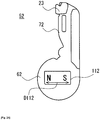
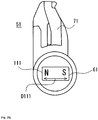
- Fig. 22 is a schematic view of the first member 51 having the first permanent magnet 111 of bar magnet.
- Fig. 23 is a schematic view of the second member 52 having the second permanent magnet 112 of bar magnet.
- Fig. 24 is a schematic cross-sectional view illustrating an embodiment where the first permanent magnet 111 housed in the first housing 101 of the first base 61 is covered by the first cover 121 and the second permanent magnet 112 housed in the second housing 102 of the second base 62 is covered by the second cover 122.
- Fig. 25 is a schematic view illustrating that the first base 61 of the first member 51 and the second base 62 of the second member 52 are overlaid.
- the second insert 72 moves toward the slit 46 of the slider 40 in accordance with magnetic repulsion effected between the first permanent magnet 111 of the first base 61 and the second permanent magnet 112 of the second base 62.
- Fig. 26 is a schematic view illustrating that the second insert 72 has been inserted in the slider 40 via the slit 46 of the slider 40 in accordance with magnetic repulsion effected between the first permanent magnet 111 of the first base 61 and the second permanent magnet 112 of the second base 62. Magnetic repulsion between the first poles of the first and second permanent magnets 111 and 112 and/or between the second poles of the first and second permanent magnets 111 and 112 would be used for pivoting the second insert 72.
- each of the permanent magnets 111, 112 has first and second poles arranged in a plane crossing or orthogonal to the rotational axis AX regarding the pivoting of the second insert 72.
- Arrangement direction Dill of the first and second poles in the first permanent magnet 111 of the first base 61 is crossing or orthogonal (i.e. non-parallel) to the rotational axis AX regarding the pivoting of the second insert 72 (See Fig. 1 ).
- Arrangement direction D112 of the first and second poles in the second permanent magnet 112 of the second base 62 is crossing or orthogonal (i.e. non-parallel) to the rotational axis AX regarding the pivoting of the second insert 72.
- the first and second bases 61 and 62 are engaged in rotatable manner, not necessarily limited to this though.
- the first base 61 has one or more engaging portion 161 and the second base 62 has one or more engaged portions 162.
- the engaging portion 161 is a protrusion and the engaged portion is a recess, but these can be interchanged.
- the recess extends in the circumferential direction regarding the rotational axis AX, for example. Accordingly, rotation of the second base 62 relative to the first base 61 or rotation of the first base 61 relative to the second base 62 in accordance with magnetic force effected between the first and second permanent magnets 111 and 112 would be facilitated.
- the first pole of the second permanent magnet 112 is positioned near the first pole of the first permanent magnet 111.
- the second pole of the second permanent magnet 112 is positioned near the second pole of the first permanent magnet 111.
- the first and second bases 61 and 62 are sandwiched between thumb and index finger of a hand of human.
- the first permanent magnet 111 cannot move away from the second permanent magnet 112 along the rotational axis AX.
- the second permanent magnet 112 cannot move away from the first permanent magnet 111 along the rotational axis AX.
- the first pole of the second permanent magnet 112 moves away from the first pole of the first permanent magnet 111 in a plane crossing or orthogonal to the rotational axis AX in accordance with magnetic repulsion effected between the same poles of the first and second permanent magnets 111 and 112 and similarly, the second pole of the second permanent magnet 112 moves away from the second pole of the first permanent magnet 111. That is, the rotation of the second base 62 relative to the first base 61 starts in accordance with magnetic repulsion effected between the same poles of the first and second permanent magnets 111 and 112. Directionality can be given to the rotational direction of the second base 62 in accordance with the adjustment of force for sandwiching them between the thumb and index finger.
- the second insert 72 pivots toward the slit 46 of the slider 40 in accordance with the above-described rotation of the second base 62 relative to the first base 61. It is an option for the first and second bases 61 and 62 to be associated in rotatable manner, but such a case allows one to control more easily a rotational direction of the second base 62 as described above.
- Figs. 27 to 30 describe embodiments where the second insert 72 is inserted into the slider 40 via the slit 46 of the slider 40 in accordance with magnetic attraction effected between the first and second permanent magnets 111 and 112 of the first and second bases 61 and 62.
- the second pole of the second permanent magnet 112 is placed near the first pole of the first permanent magnet 111 and likewise, the first pole of the second permanent magnet 112 is placed near the second pole of the first permanent magnet 111.
- the second pole of the second permanent magnet 112 moves closer to the first pole of the first permanent magnet 111 in a plane crossing or orthogonal to the rotational axis AX in accordance with magnetic attraction effected between the opposite poles of the first and second permanent magnets 111 and 112 and likewise, the first pole of the second permanent magnet 112 moves closer to the second pole of the first permanent magnet 111. That is, the rotation of the second base 62 relative to the first base 61 starts in accordance with magnetic attraction effected between the opposite poles of the first permanent magnet 111 and the second permanent magnet 112. This is accompanied by the second insert 72 pivoting toward the slit 46 of the slider 40. It is an option for the first base 61 and the second base 62 to be associated in rotatable manner, but such a case allows one to control more easily the rotational direction of the second base 62 as described above.
Landscapes
- Slide Fasteners (AREA)
- Telephone Set Structure (AREA)
- Slide Fasteners, Snap Fasteners, And Hook Fasteners (AREA)
- Purses, Travelling Bags, Baskets, Or Suitcases (AREA)
Abstract
Description
- The present disclosure is related to a stop member and a slide fastener including the same.
-
Patent literatures Patent literature 1 discloses a support member 7 provided with agroove portion 15, and an insertion member 8 having a protruded portion 20 to be inserted into thegroove portion 15. Thegroove portion 15 is provided with a magnet or magnetic body. The protruded portion 20 is provided with a magnet or magnetic body therein. The protruded portion 20 and thegroove portion 15 are magnetically attracted each another, and the protruded portion 20 is automatically inserted into the groove portion 15 (See para. 0037 of Patent literature 1). -
Patent literature 2 discloses a method of attaching a magnet shown in itsFigs. 5 and6 . -
- [Patent literature 1] Japanese Utility-Model Registration No.
3,170,902 - [Patent literature 2] Japanese Patent No.
4,152,216 - The present inventors have newly identified a technical problem that, in the case of
Patent literature - Stop member according to an aspect of the present disclosure includes: a first member including a first insert to be inserted into a slider via a rear mouth of the slider, and a first base positioned rearward of the first insert; and a second member including a second insert to be inserted into the slider via a slit extending between the rear mouth and a front mouth of the slider, and a second base to be overlaid onto the first base. The first and second bases are configured to effect magnetic attraction and/or repulsion between the first and second bases, when the first and second bases are overlaid. The second base rotates relative to the first base in accordance with the magnetic attraction and/or repulsion to allow the second insert to pivot toward the slit. In some embodiments, the second base starts to rotate relative to the first base in accordance with magnetic attraction between the first and second bases. In some embodiments, the second base starts to rotate relative to the first base in accordance with magnetic repulsion between the first and second bases.
- In some embodiments, the first and second bases are configured to effect magnetic attraction between the first and second bases when the first and second bases are overlaid. The second base rotates relative to the first base in a process of magnetic attachment of the first and second bases in accordance with the magnetic attraction.
- In some embodiments, in accordance with the magnetic attraction, the second base moves closer to the first base in an axial direction of a rotational axis regarding the pivoting of the second insert and accordingly, the second insert pivots about the rotational axis.
- In some embodiments, at least one of the first and second bases is provided with a permanent magnet.
- In some embodiments, the permanent magnet has first and second poles arranged along a rotational axis regarding the pivoting of the second insert.
- In some embodiments, the first and second bases are configured to effect magnetic repulsion when the first and second bases are overlaid, and the second base rotates relative to the first base in accordance with the magnetic repulsion.
- In some embodiments, the first and second bases are respectively provided with first and second permanent magnets.
- In some embodiments, each of the first and second permanent magnets has first and second poles arranged in a plane crossing or orthogonal to a rotational axis AX regarding the pivoting of the second insert.
- In some embodiments, the first and second bases are engageable in a rotatable manner.
- In some embodiments, the permanent magnet is housed in a housing of the first or second base.
- In some embodiments, one of the first and second bases includes a sloped surface that extends about a rotational axis regarding the pivoting of the second insert and the other one of the first and second bases includes a sliding portion that slides on the sloped surface.
- In some embodiments, one of the first base and the second base is provided with an axial portion and the other one of the first base and the second base is provided with a receiving portion that receives the axial portion.
- In some embodiments, the first base is provided with the axial portion, the first base has a first housing for housing a first permanent magnet, and the first housing has a bottom positioned in the proximity of an end of the axial portion.
- In some embodiments, the second base is provided with the receiving portion, the second base has a second housing for housing a second permanent magnet, and the second housing has a bottom positioned in the proximity of a bottom of the receiving portion.
- A stop member according to an aspect of the present disclosure includes: a first member including a first insert to be inserted into a slider via a rear mouth of the slider and a first base positioned rearward of the first insert; and a second member including a second insert to be inserted into the slider via a slit extending between the rear mouth and a front mouth of the slider and a second base to be overlaid onto the first base. The first and second bases are configured to effect magnetic attraction and/or repulsion between the first and second bases when the first and second bases are overlaid. One of the first and second bases includes a sloped surface that extends about a rotational axis AX regarding the pivoting of the second insert and the other one of the first and second bases includes a sliding portion that slides on the sloped surface.
- In some embodiments, the sloped surface is provided to convert displacement of the second base in an axial direction of the rotational axis to displacement of the second base about the rotational axis.
- Slide fastener according to an aspect of the present disclosure has the above-described stop member.
- According to an aspect of the present disclosure, stop member may be provided with improved operability.
-
- [
Fig. 1] Fig. 1 is a schematic elevational view of a rear end of a slide fastener provided with a stop member according to an aspect of the present disclosure. First and second fastener stringers are closed, and illustration of a slider positioned frontward of the stop member of the slide fastener is omitted. - [
Fig. 2] Fig. 2 is a schematic perspective view of a non-limiting exemplary slider in a slide fastener according to an aspect of the present disclosure. - [
Fig. 3] Fig. 3 is a schematic side view of a non-limiting exemplary slider in a slide fastener according to an aspect of the present disclosure. - [
Fig. 4] Fig. 4 is schematic perspective view of a first member according to an aspect of the present disclosure. - [
Fig. 5] Fig. 5 is a schematic perspective view of a first member according to an aspect of the present disclosure, illustrating a structure of the first member at the opposite side compared withFig. 4 . - [
Fig. 6] Fig. 6 is a schematic perspective view of a first member according to an aspect of the present disclosure with the first member viewed obliquely from another point compared withFig. 5 . - [
Fig. 7] Fig. 7 is a schematic perspective view of a second member according to an aspect of the present disclosure. - [
Fig. 8] Fig. 8 is a schematic perspective view of a second member according to an aspect of the present disclosure, illustrating a structure of the second member at the opposite side compared withFig. 7 . - [
Fig. 9] Fig. 9 is a schematic cross-sectional view of a stop member taken along a chain line X9-X9 inFig. 1 . - [
Fig. 10] Fig. 10 is a schematic bottom view of a first member without illustration of first cover. - [
Fig. 11] Fig. 11 is a schematic cross-sectional view of a first member taken along a chain line X11-X11 inFig. 10 , illustration of first permanent magnet and first cover are omitted. - [
Fig. 12] Fig. 12 is a schematic top view of a second member, illustration of second cover is omitted. - [
Fig. 13] Fig. 13 is a schematic cross-sectional view of a second member taken along a chain line X13-X13 inFig. 12 , illustration of second permanent magnet and second cover are omitted. - [
Fig. 14] Fig. 14 is a schematic perspective view of a first cover. - [
Fig. 15] Fig. 15 is a schematic perspective view of a second cover. - [
Fig. 16] Fig. 16 is a schematic bottom view of a first member in which a first cover is attached to a first base. - [
Fig. 17] Fig. 17 is a schematic cross-sectional view of a first member taken along a chain line X17-X17 inFig. 16 with a first cover attached to a first base. - [
Fig. 18] Fig. 18 is a schematic top view of a second member with a second cover attached to a second base. - [
Fig. 19] Fig. 19 is a schematic cross-sectional view of a second member taken along a chain line X19-X19 inFig. 18 with a second cover attached to a second base. - [
Fig. 20] Fig. 20 is a schematic view illustrating a process of magnetic attachment of the first and second bases in which a sliding portion slides down a sloped surface and a second insert of second member moves toward a slit of slider, and depicting a condition before the second insert enters into the slider via the slit of the slider. - [
Fig. 21] Fig. 21 is a schematic view illustrating a process of magnetic attachment of the first and second bases in which a sliding portion slides down a sloped surface and a second insert of second member moves toward a slit of slider, depicting a condition after the second insert entered into the slider via the slit of the slider. - [
Fig. 22] Fig. 22 is a schematic view of a first member having a first permanent magnet of bar magnet. - [
Fig. 23] Fig. 23 is a schematic view of a second member having a second permanent magnet of bar magnet. - [
Fig. 24] Fig. 24 is a schematic cross-sectional view illustrating an embodiment where a first permanent magnet housed in a first housing of the first base is covered by a first cover and a second permanent magnet housed in a second housing of second base is covered by a second cover. - [
Fig. 25] Fig. 25 is a schematic view illustrating that a first base of first member and a second base of second member are overlaid. Second insert moves toward a slit of slider in accordance with magnetic repulsion effected between first and second permanent magnets of first and second bases. - [
Fig. 26] Fig. 26 is a schematic view illustrating that a second insert has been inserted in a slider via a slit of the slider in accordance with magnetic repulsion effected between first and second permanent magnets of first and second bases. - [
Fig. 27] Fig. 27 is a schematic view of a first member having a first permanent magnet of bar magnet. - [
Fig. 28] Fig. 28 is a schematic view of a second member having a second permanent magnet of bar magnet. - [
Fig. 29] Fig. 29 is a schematic view illustrating that first and second bases of first and second members are overlaid. Second insert moves toward a slit of slider in accordance with magnetic attraction effected between first and second permanent magnets of first and second bases. - [
Fig. 30] Fig. 30 is a schematic view illustrating that a second insert has been inserted in a slider via a slit of slider in accordance with magnetic attraction effected between first and second permanent magnets of first and second bases. - Hereinafter, embodiments of the present invention will be described with reference to
Figs. 1 to 30 . A skilled person would be able to combine respective embodiments and/or respective features without requiring excess descriptions. Also, a skilled person would appreciate synergistic effects of such combinations. Overlapping descriptions among the exemplary embodiments would be basically omitted. Referenced drawings are mainly for describing inventions, and may possibly be simplified for the sake of convenience of illustration. Individual features may possibly be highlighted by an expression "in some embodiments". Individual features will be understood as universal feature which is not only effective to disclosed stop members but also effective to undisclosed stop members. -
Fig. 1 is a schematic elevational view of a rear end of aslide fastener 1 provided with astop member 50 according to an aspect of the present disclosure. First andsecond fastener stringers Figs. 2 and 3 ) positioned frontward of thestop member 50 of theslide fastener 1 is omitted.Fig. 2 is a schematic perspective view of a non-limitingexemplary slider 40 included in theslide fastener 1.Fig. 3 is a schematic side view of a non-limitingexemplary slider 40 included in theslide fastener 1. -
Slide fastener 1 has first andsecond fastener stringers slider 40 for opening and closing the first andsecond fastener stringers first fastener stringer 31 has afirst fastener tape 11 andfirst fastener elements 21 provided on the side-edge, extending in the lengthwise direction, of thefirst fastener tape 11. Thesecond fastener stringer 32 has asecond fastener tape 12, andsecond fastener elements 22 provided on a side-edge, extending in the lengthwise direction, of thesecond fastener tape 12. -
Fastener tape fastener tape fastener element first fastener tape 11 with thefirst fastener element 21 and the side-edge of thesecond fastener tape 12 with thesecond fastener element 22 are arranged to face one another, and thus may be referred to as opposed side-edges. - Frontward movement of
slider 40 closes the first andsecond fastener stringers slider 40 opens the first andsecond fastener stringers slider 40. The first andsecond fastener stringers second fastener stringers fastener tapes fastener elements - Left-and-Right direction is a direction orthogonal to the Front-and-Rear direction and parallel to a tape surface of
respective fastener tapes slider 40 extends. Redefining the Font-and-Rear direction, Left-and-Right direction, and Up-and-Down direction would be possible based on other descriptions in the present specification. - As shown in
Figs. 2 and 3 , theslider 40 has atop wing 41, abottom wing 42, and an interconnectingpost 43 that interconnects thetop wing 41 and thebottom wing 42. Paired left and rightfront mouths 44 are arranged to sandwich the interconnectingpost 43.Rear mouth 45 is arranged at the opposite side relative to thefront mouth 44 in the front-and-rear direction. Left slit (or tape-passage) 46, allowing thefirst fastener tape 11 to move there-though, extends between the left-side front mouth 44 and therear mouth 45. Right slit 46, allowing thesecond fastener tape 12 to move there-through, extends between the right-side front mouth 44 and therear mouth 45. - The
slider 40 has Y-shaped element-passage bifurcated by the interconnectingpost 43 between thetop wing 41 and thebottom wing 42.First fastener elements 21 enter in and go out from theslider 40 via the left-side front mouth 44.Second fastener elements 22 enter in and go out from theslider 40 via the right-side front mouth 44. Engaged first andsecond fastener elements slider 40 via therear mouth 45. -
Top wing 41 of theslider 40 includes atop wing plate 41a and pairedtop flanges 41b protruded downward at the left and right side-edges of thetop wing plate 41a.Bottom wing 42 includes abottom wing plate 42a and pairedbottom flanges 42b protruded upward at the left and right side-edges of thebottom wing plate 42a. In some cases, one of the top andbottom flanges top wing plate 41a and thebottom wing plate 42a may be arranged in a plane orthogonal to Up-and-Down direction along which the interconnectingpost 43 extends. Optionally, theslider 40 has a pull-attachment column 48 and apull tab 49 attached to thetop wing plate 41a via the pull-attachment column 48. Optionally, theslider 40 has a lockingpawl 47 to be operated by thepull tab 49. Note that, theslider 40 may be made of metal, resin or other material. -
Slide fastener 1 has astop member 50 additionally to the above-described first andsecond fastener stringers stop member 50 defines a stop position for theslider 40. Thestop member 50 of the present disclosure has first andsecond members second members second fastener stringers stop member 50 may be referred to as a separable stop. Thefirst member 51 is secured to thefirst fastener tape 11 and positioned rearward of thefirst fastener element 21. Thesecond member 52 is secured to thesecond fastener tape 12 and positioned rearward of thesecond fastener element 22. The first orsecond member terminal end second fastener tape stop member 50 is provided at the terminal of thefastener stringer fastener tape fastener elements second members -
Fig. 4 is schematic perspective view of thefirst member 51.Fig. 5 is a schematic perspective view of thefirst member 51, illustrating a structure of the first member at the opposite side compared withFig. 4 .Fig. 6 is a schematic perspective view of thefirst member 51 which is viewed obliquely from a different point compared withFig. 5 .Fig. 7 is a schematic perspective view of thesecond member 52.Fig. 8 is a schematic perspective view of thesecond member 52, illustrating a structure of thesecond member 52 at the opposite side compared withFig. 7 .Fig. 9 is a schematic cross-sectional view of the stop member taken along a chain line X9-X9 inFig. 1 . - As would be understood by referring to
Figs. 1 and4-8 , thefirst member 51 has afirst insert 71 to be inserted into theslider 40 via therear mouth 45 of theslider 40 of theslide fastener 1; and afirst base 61 positioned rearward of thefirst insert 71. Thesecond member 52 includes asecond insert 72 to be inserted into theslider 40 via theslit 46 extending between therear mouth 45 and thefront mouth 44 of theslider 40, and asecond base 62 to be overlaid onto thefirst base 61. - As would be well understood from
Fig. 9 and the following descriptions, in the present embodiment, the first andsecond bases Fig.9 , magnetic attraction) between the first andsecond bases second bases second base 62 rotates relative to thefirst base 61 in accordance with the magnetic attraction and/or repulsion to allow thesecond insert 72 to pivot toward theslit 46. Accordingly, thestop member 50 with improved operability can be provided. - The
first insert 71 extends along the Front-and-Rear direction between thefirst base 61 and thefirst fastener elements 21. Thesecond insert 72 extends along the Front-and-Rear direction between thesecond base 62 and thesecond fastener elements 22. Thefirst insert 71 has agroove 73 into which thesecond insert 72 is inserted. Thegroove 73 extends in the Front-and-Rear direction and is opening at front, rear and right sides. Thegroove 73 receives thesecond insert 72 which has entered into theslider 40 via the right-side slit 46 of theslider 40 while thefirst insert 71 has been inserted into theslider 40. Thesecond insert 72 is inserted into thegroove 73 of thefirst insert 71 so that upward-and-downward displacement of thesecond insert 72 is restricted. - The
first member 51 may be configured to facilitate to keep theslider 40 stationary on thefirst member 51. It is facilitated that thesecond insert 72 can enter into theslider 40 via the right-side slit 46 of theslider 40 while thefirst insert 71 has been inserted into theslider 40. - Additionally to the
first insert 71, thefirst member 51 may have one or any combination of athin plate 74, aguide 75, and a stoppingwall 76.Thin plate 74 is arranged adjacent to thefirst insert 71 in the left-and-right direction.Thin plate 74 has a thickness that enables its insertion into theslit 46 of theslider 40.Guide 75 is projected from thethin plate 74 in Up-and-Down direction and extends along the Front-and-Rear direction. Embodiments are envisioned where theguide 75 is protruded from thethin plate 74 upward only or downward only.Groove 77 is formed between thefirst insert 71 and theguide 75, and a flange portion of theslider 40 is inserted into thegroove 77. Note that likewise theguide 75, thefirst insert 71 is protruded from thethin plate 74 in Up-and-down direction. The stoppingwall 76 extends in Left-and-Right direction and is coupled to thefirst insert 71, thethin plate 74, and theguide 75. The stoppingwall 76 defines a stop position for theslider 40. - The
first base 61 is positioned rearward of thefirst insert 71, and is directly or indirectly coupled to thefirst insert 71. Indirect coupling of thefirst base 61 with thefirst insert 71 indicates that thefirst base 61 is coupled with thefirst insert 71 via another or other structural portion(s) such as the stoppingwall 76. Thefirst base 61 has aflat plate 63, anaxial portion 81, and asloped surface 83. Theaxial portion 81 is arranged in and protruded downward from the bottom surface theflat plate 63. Theaxial portion 81 has a portion with a diameter reduced toward theend 91. Theaxial portion 81 has anend surface 81a in itsend 91, and an outerperipheral surface 81b in the outer periphery of theend surface 81a. Flattenedend surface 81a reduces a stimulus otherwise given to a human skin by theaxial portion 81. The slopedsurface 83 extends about a rotational axis AX regarding the pivoting of thesecond insert 72. The slopedsurface 83 extends in an arc about the rotational axis AX, but embodiments are envisioned where it extends across the entire circle about the rotational axis AX. The slopedsurface 83 extends between the outerperipheral surface 81b of theaxial portion 81 and the bottom surface of theflat plate 63. Particularly, in some cases, the slopedsurface 83 is arranged to convert displacement of thesecond base 62 in the axial direction of the rotational axis AX to displacement of thesecond base 62 about the rotational axis AX. - The
second insert 72 of thesecond member 52 includes a portion which is capable of entering into theslider 40 via theslit 46 of theslider 40. For example, thesecond insert 72 is a flat plate with a thickness enabling the passing via theslit 46 of theslider 40. Thesecond insert 72 has a side-edge 72a that touches thetop wing 41 or thebottom wing 42 of theslider 40. The side-edge 72a of thesecond insert 72 has a shape that matches a side part of the profile of the top orbottom wing slider 40. The side-edge 72a of thesecond insert 72 has arecess 72b for avoiding interference with acorner 42c of theslider 40. - The
second member 52 has aguide 85 and athird fastener element 23 additionally to thesecond insert 72. Theguide 85 is protruded in both sides of upward and downward from thesecond insert 72, and extends in the Front-and-Rear direction. Thisguide 85 defines a passage for theslider 40. Thethird fastener element 23 is coupled to the front end of thesecond insert 72 and is positioned between thesecond insert 72 and thesecond fastener element 22. When thesecond insert 72 is inserted into theslider 40 via theslit 46 which extends between therear mouth 45 and thefront mouth 44 of theslider 40, thethird fastener element 23 is positioned adjacent to and frontward of thefront mouth 44 of theslider 40. Frontward movement of theslider 40 allows thethird fastener element 23 to be inside theslider 40 and, in turn, be engaged with thefirst fastener element 21 inside the slider 40 (SeeFig. 1 ). - The
third fastener element 23 has a groove 24 and thefirst insert 71 has aninsertion portion 25. Theinsertion portion 25 of thefirst insert 71 is inserted into the groove 24 of the third fastener element 23 (seeFig. 1 ), thus suppressing the front ends of the first andsecond members 51 52 from being separated in Up-and-Down direction. - The
second base 62 has a receivingportion 82 that receives theaxial portion 81 of thefirst base 61, and a slidingportion 84 that slides on the slopedsurface 83 provided in thefirst base 61. The receivingportion 82 has abottom surface 82a that is opposed to theend surface 81a of theaxial portion 81, and an outerperipheral surface 82b that is opposed to the outerperipheral surface 81b of theaxial portion 81. Thebottom surface 82a is a substantially flat surface but should not be limited to this. The outerperipheral surface 82b is a slant surface that slants obliquely relative to thebottom surface 82a. The slidingportion 84 is arranged to protrude into the internal space of the receivingportion 82. When thefirst base 61 and thesecond base 62 are overlaid, the slidingportion 84 is protruded radially inward of the rotational axis AX regarding the pivoting of thesecond insert 72. The slidingportion 84 has a projectedpart 84a. When the slidingportion 84 finishes in sliding across the slopedsurface 83, the projectedpart 84a of the slidingportion 84 is inserted into arecess 81c of the axial portion 81 (SeeFig. 6 ). - Note that embodiments are obviously envisioned where the
second base 62 is provided with theaxial portion 81 and thefirst base 61 is provided with the receivingportion 82. Embodiments are naturally envisioned where thesecond base 62 is provided with the slopedsurface 83 and thefirst base 61 is provided with the slidingportion 84. Note that, theaxial portion 81 and the receivingportion 82 are provided for a purpose of positioning when stacking the first andsecond bases second bases - The first and
second bases Fig. 9 ) between the first andsecond bases second bases second base 62 is rotatable relative to thefirst base 61 in accordance with the magnetic attraction and/or repulsion to allow thesecond insert 72 to pivot towards theslit 46. Accordingly, thestop member 50 with improved operability can be provided. - There are various ways in terms of how the above-described magnetic attraction and/or repulsion is effected. In some cases, the magnetic attraction is effected based on the use of at least one permanent magnet. In some cases, the magnetic repulsion is effected based on the use of permanent magnets respectively provided in the first and
second bases - Specifically, the following cases are envisaged: (i) the
first base 61 has one or more permanent magnets, and thesecond base 62 has one or more magnetic bodies; (ii) thefirst base 61 has one or more magnetic bodies, and thesecond base 62 has one or more permanent magnets; and (iii) thefirst base 61 has one or more permanent magnets, and thesecond base 62 has one or more permanent magnets. Use of the permanent magnet and the magnetic body can effect the magnetic attraction. Use of the permanent magnet and the permanent magnet can effect the magnetic attraction and/or repulsion. When thefirst base 61 and thesecond base 62 are overlaid, if a first pole (e.g. N-pole) of the permanent magnet in thefirst base 61 and a second pole (e.g. S-pole) of the permanent magnet in thesecond base 62 are arranged closely, the magnetic attraction would be effected between them. When thefirst base 61 and thesecond base 62 are overlaid, if a first pole (e.g. N-pole) of the permanent magnet in thefirst base 61 and a first pole (e.g. N-pole) of the permanent magnet in thesecond base 62 are arranged closely, the magnetic repulsion would be effected between them. - The permanent magnet has first and second poles as widely known. The first pole is one of N-pole and S-pole and the second pole is the other one of N-pole and S-pole. The magnetic body can be made of any material magnetically attachable to the permanent magnet and, for example, including one or more metals selected from Iron (Fe), Cobalt (Co), Nickel (Ni), and Gadolinium (Gd). Magnetic body can include stainless-steel such as martensite, ferrite, and austenite-ferrite. Note that the stainless-steel is an alloy and, in fact, includes Iron (Fe). The permanent magnet and magnetic body can take various shapes such as a bar, circular plate, and ring. Embodiments are envisioned where particulate permanent magnets and magnetic bodies are used.
- The permanent magnet and/or magnetic body can be variously provided in the
first base 61 and thesecond base 62. Embodiments are envisioned where the permanent magnet and/or magnetic body is embedded in thefirst base 61 through insert-molding or other methods. Embodiments are envisioned where the permanent magnet and/or magnetic body is fitted with or secured, by adhesive, to thefirst base 61. Embodiments are envisioned where thefirst base 61 is provided with a housing for hosing the permanent magnet and/or magnetic body. Similar embodiments are envisioned for thesecond base 62 either. - Embodiments are envisioned where the first member 51 (or the first base 61) or the second member 52 (or the second base 62) itself is made of magnetic material. For example, the
first member 51 or thesecond member 52 is produced by casting of magnetic metal. Attachment of thefirst member 51 to thefirst fastener tape 11 can be achieved by any methods such as sewing and gluing. The same applies to attachment of thesecond member 52 to thesecond fastener tape 12. Note that, in typical cases, thefirst member 51 is fixed to thefirst fastener tape 11 as a result of insert-molding using a plastic/resin. Likewise, thesecond member 52 is fixed to thesecond fastener tape 12. In cases where the first member 51 (or the first base 61) or the second member 52 (or the second base 62) itself is made of magnetic material, thefirst base 61 or thesecond base 62 can additionally have a permanent magnet or magnetic body. - Referring to
Figs. 10-13 , embodiments will be described where thefirst base 61 is provided with afirst housing 101 for housing the firstpermanent magnet 111 and thesecond base 62 is provided with asecond housing 102 for housing the secondpermanent magnet 112. Note that replacing one of the first and secondpermanent magnets permanent magnets -
Fig. 10 is a schematic bottom view of thefirst member 51 without illustration of afirst cover 121.Fig. 11 is a schematic cross-sectional view of thefirst member 51 taken along a chain line X11-X11 inFig. 10 , illustration of a firstpermanent magnet 111 and thefirst cover 121 are omitted.Fig. 12 is a schematic top view of thesecond member 52, illustration of asecond cover 122 is omitted.Fig. 13 is a schematic cross-sectional view of thesecond member 52 taken along a chain line X13-X13 inFig. 12 , illustration of a secondpermanent magnet 112 and thesecond cover 122 are omitted. - The
first base 61 has thefirst housing 101 that houses the firstpermanent magnet 111. In some embodiments, thefirst housing 101 is provided to form a hollow in theaxial portion 81. In some embodiments, thefirst housing 101 has an opening OP101 for introducing the firstpermanent magnet 111 from the opposite side of the end 91 (e.g. theend surface 81a) of theaxial portion 81. The firstpermanent magnet 111 is introduced into thefirst housing 101 via the opening OP101 of thefirst housing 101. In some embodiments, thefirst housing 101 has a bottom 106 at the side of theend 91 of theaxial portion 81. Note that, thefirst housing 101 has acircumferential wall surface 101a extending along the depth direction of thefirst housing 101 and abottom surface 101b that is crossing or orthogonal to the depth direction of thefirst housing 101. - Cross-sectional shape of the
first housing 101 in a plane orthogonal to the depth direction of thefirst housing 101 may take any shape such as a circle, triangle, rectangle and pentagon. It is envisioned that the cross-sectional shape of thefirst housing 101 changes along the depth direction of thefirst housing 101. Note that, the depth direction of thefirst housing 101 matches or is parallel to the axial direction AX1 of theaxial portion 81. Note that, the axial direction AX1 of theaxial portion 81 is co-axially arranged with the rotational axis AX regarding the pivoting of thesecond insert 72. - The
bottom 106 of thefirst housing 101 is positioned in the proximity of the end 91 (e.g. theend surface 81a) of theaxial portion 81. Distance between the bottom 106 of thefirst housing 101 and theend 91 of theaxial portion 81 may be reduced, thus increasing magnetic permeability. First thinnedportion 108 is provided between theend surface 81a of theaxial portion 81 and thebottom surface 101b of thefirst housing 101. It is envisioned that one or more magnetically permeable holes are arranged in the first thinnedportion 108 to further facilitate transmission of magnetic field lines there-through. The magnetically permeable holes are holes with permeability of magnetic fields and should not be limited to a space. The first thinnedportion 108 is not necessarily a layer-like portion with a constant thickness. - The
second base 62 has thesecond housing 102 that houses the secondpermanent magnet 112. In some embodiments, thesecond housing 102 of thesecond base 62 is provided at the opposite side relative to the receivingportion 82 of thesecond base 62. In some embodiments, thesecond housing 102 has an opening OP102 for introducing the secondpermanent magnet 112 from the opposite side of the opening of the receivingportion 82. The secondpermanent magnet 112 is introduced into thesecond housing 102 via the opening OP102 of thesecond housing 102. In some embodiments, thesecond housing 102 has a bottom 107 at the side of the receivingportion 82. Note that, thesecond housing 102 has acircumferential wall surface 102a extending along the depth direction of thesecond housing 102 and abottom surface 102b crossing or orthogonal to the depth direction of thesecond housing 102. - Cross-sectional shape of the
second housing 102 in a plane orthogonal to the depth direction of thesecond housing 102 can take any shape such as a circle, triangle, rectangle, and pentagon, for example. It is envisioned that the cross-sectional shape of thesecond housing 102 changes along the depth direction of thesecond housing 102. Note that the depth direction of thesecond housing 102 is opposite to the depth direction of the receivingportion 82. - The
bottom 107 of thesecond housing 102 is positioned in the proximity of the bottom 92 (e.g. thebottom surface 82a) of the receivingportion 82. Distance between the bottom 107 of thesecond housing 102 and the bottom 92 of the receivingportion 82 may be reduced, thus increasing magnetic permeability. Second thinnedportion 109 is provided between the bottom 92 (e.g. thebottom surface 82a) of the receivingportion 82 and the bottom 107 (e.g. thebottom surface 102b) of thesecond housing 102. It is envisioned that one or more magnetically permeable holes are arranged in the second thinnedportion 109 to further facilitate transmission of magnetic field lines there-through. The magnetically permeable holes are holes with permeability for magnetic fields lines and should not be limited to a space. The second thinnedportion 109 is not necessarily a layer-like portion with a constant thickness. - In some embodiments, the depth D101 of the
first housing 101 of thefirst base 61 is greater than the depth D102 of thesecond housing 102 of thesecond base 62. This facilitates that thefirst housing 101 can have a greater accommodating space in a limited volume of thefirst base 61 provided with theaxial portion 81. This facilitates to increase the size of the firstpermanent magnet 111 arranged in thefirst housing 101. - In some embodiments, the width W102 of the
second housing 102 in a plane orthogonal to the depth direction of the receivingportion 82 is greater than the width W101 of thefirst housing 101 in a plane orthogonal to the axial direction of theaxial portion 81. This facilitates that thesecond housing 102 can have a greater housing space in a limited volume of thesecond base 62 provided with the receivingportion 82. This facilitates to increase the size of the secondpermanent magnet 112 arranged in thesecond housing 102. - Each of the
permanent magnet second insert 72. Arrangement direction Dill, D112 (SeeFig. 9 ) of the first and second poles in the firstpermanent magnet 111 and/or the secondpermanent magnet 112 are parallel to the rotational axis AX regarding the pivoting of the second insert 72 (SeeFig. 1 ). The arrangement direction Dill of the first and second poles of the firstpermanent magnet 111 housed in thefirst housing 101 is parallel to the depth direction of thefirst housing 101 and/or the axial direction AX1 of theaxial portion 81. The arrangement direction D112 of the first and second poles of the secondpermanent magnet 112 housed in thesecond housing 102 is parallel to the depth direction of thesecond housing 102 and/or the depth direction of the receivingportion 82. - In some embodiments, the first
permanent magnet 111, housed in thefirst housing 101 of thefirst base 61, is shaped like a cylinder and, in the other hand, the secondpermanent magnet 112, housed in thesecond housing 102 of thesecond base 62, is shaped like a circular plate. This facilitates to allow the permanent magnet to exert greater magnetic force in a limited volume of the base portion provided with theaxial portion 81 or the receivingportion 82. Likewise, in cases where the permanent magnet is replaced by magnetic body, the extent of magnetic interaction may be greater. As indicated above, one out of the two permanent magnets can be replaced by a magnetic body. - The cross-sectional shape of the
first housing 101 and the cross-sectional shape of the first permanent magnet 111 (housed in the first housing 101) in a plane orthogonal to the depth direction of thefirst housing 101 are the same or different. Typically, both are shaped like a circle, facilitating smoother insertion of the permanent magnet into the housing. The cross-sectional shape of thesecond housing 102 and the cross-sectional shape of the second permanent magnet 112 (housed in the second housing 102) in a plane orthogonal to the depth direction of thesecond housing 102 are the same or different. Typically, both are shaped like a circle, facilitating smoother insertion of the permanent magnet into the housing. - Embodiments are envisaged where one or more position-restricting portion (e.g. a protrusion, a recess or combination of them) for restricting displacement of the permanent magnet is provided in one or both housings.
- As a method for securing the first
permanent magnet 111 in thefirst housing 101, various manners are envisioned such as gluing, fitting or closing by a cover. The same applies to a method for securing the secondpermanent magnet 112 in thesecond housing 102. - With reference to
Figs. 14-19 , embodiments will be described where the opening OP101 of thefirst housing 101 is closed by afirst cover 121, and the opening OP102 of thesecond housing 102 is closed by asecond cover 122. In particular, embodiments will be described where thefirst cover 121 is secured, by fitting, to the first member 51 (or the first base 61) and thesecond cover 122 is secured, by fitting, to the second member 52 (or the second base 62), but should not be limited to this. For example, additionally or alternatively to the fitting, the cover can be fixed to the base portion by adhesive. -
Fig. 14 is a schematic perspective view of thefirst cover 121.Fig. 15 is a schematic perspective view of thesecond cover 122.Fig. 16 is a schematic bottom view of thefirst member 51 in which thefirst cover 121 is attached to thefirst base 61.Fig. 17 is a schematic cross-sectional view of thefirst member 51 taken along a chain line X17-X17 inFig. 16 with thefirst cover 121 attached to thefirst base 61.Fig. 18 is a schematic top view of thesecond member 52 with thesecond cover 122 attached to thesecond base 62.Fig. 19 is a schematic cross-sectional view of thesecond member 52 taken along a chain line X19-X19 inFig. 18 with thesecond cover 122 attached to thesecond base 62. - Each of the first and second cover 121,122 has a covering
portion 131 and one or moreengaging protrusions 132. In the illustrated case, each cover is provided with two engagingprotrusions 132. The coveringportion 131 is a portion that covers the opening of the housing into which the permanent magnet or the magnetic body is inserted. The engagingprotrusion 132 is a portion that prevents the cover from coming off the stop member or the base portion. Each engagingprotrusion 132 has apost 133 provided on the coveringportion 131 and anengagement head 134 provided at the end of thepost 133. Embodiments are envisaged where the coveringportion 131 is provided with arotation stop 135 as illustrated. Note that, in the case where adhesive is used, the engagingprotrusions 132 can be omitted. - The first and
second bases fourth housings respective covering portion 131 of thecover respective covering portion 131 of the cover 121,122. Note that thethird housing 103 is in spatial communication with thefirst housing 101. Likewise, thefourth housing 104 is in spatial communication with thesecond housing 102. - In cases where each cover 121,122 is provided with the engaging
protrusion 132, the first andsecond bases protrusions 132 are respectively engaged. The firstengaged portion 141 is provided radially outwardly offset from the axial direction AX1 of theaxial portion 81. Therefore, when engaged with the first engagedportion 141, the engagingprotrusion 132 of thefirst cover 121 is positioned radially outwardly offset from the axial direction AX1 of theaxial portion 81. The firstengaged portion 141 may be provided to penetrate through the outerperipheral surface 81b of theaxial portion 81 and a surface of thefirst base 61 at the opposite side of theaxial portion 81, but not necessarily limited to this. The firstengaged portion 141 has a lockingsurface 151 by which theengagement head 134 of the engagingprotrusion 132 is locked. - The second
engaged portion 142 is positioned outwardly offset from the bottom 92 of the receivingportion 82. Therefore, when engaged with the secondengaged portion 142, the engagingprotrusion 132 of thesecond cover 122 is positioned outwardly offset from the bottom 92 of the receivingportion 82. The secondengaged portion 142 is provided to penetrate through the outerperipheral surface 82b about thebottom surface 82a of the receivingportion 82 and a surface of thesecond base 62 at the opposite side of the receivingportion 82, but not necessarily limited to this. The secondengaged portion 142 has a lockingsurface 152 by which theengagement head 134 of the engagingprotrusion 132 is locked. - Operation of the
stop member 50 of the present disclosure will be described with reference toFigs. 20 and21 .Figs. 20 and21 are a schematic view illustrating that, while the first andsecond bases portion 84 slides down a slopedsurface 83 and thesecond insert 72 of thesecond member 52 moves toward theslit 46 of theslider 40.Fig. 20 illustrates a condition before thesecond insert 72 enters into theslider 40 via theslit 46 of theslider 40.Fig. 21 illustrates a condition after thesecond insert 72 has entered into theslider 40 via theslit 46 of theslider 40. - Firstly, in order to close the first and
second fastener stringers second bases first insert 71 has been inserted into theslider 40 beforehand. Theslider 40 is held stationary on thefirst member 51. When the first andsecond bases second base 62 moves toward thefirst base 61 in accordance with the magnetic attraction effected between them. Theaxial portion 81 of thefirst base 61 enters into the receivingportion 82 of thesecond base 62. The slidingportion 84 touches the slopedsurface 83. Reduction in the interspace between the first andsecond bases portion 84 on the slopedsurface 83. Accordingly, thesecond base 62 rotates relative to thefirst base 61 and thesecond insert 72 pivots about the rotational axis AX toward theslit 46 of theslider 40. Finally, thesecond insert 72 enters into theslider 40 via theslit 46 of theslider 40. In short, thesecond base 62 moves toward thefirst base 61 in accordance with the magnetic attraction in the axial direction of the rotational axis AX regarding the pivoting of thesecond insert 72, and thesecond insert 72 pivots about the rotational axis AX. - As shown in
Fig. 21 , following that thesecond insert 72 has entered into theslider 40 via theslit 46 of theslider 40, theslider 40 is moved frontward and thefastener stringers first fastener element 21 and thethird fastener element 23 are engaged and in turn, thefirst fastener elements 21 and thesecond fastener elements 22 are engaged. - Magnetic attraction between the first and
second bases second base 62 relative to thefirst base 61 while thefirst base 61 and thesecond base 62 approach one another. For a person operating thestop member 50, just overlaying thefirst base 61 and thesecond base 62 would let thesecond insert 72 automatically pivot towards theslit 46 of theslider 40. Operational burden for inserting thesecond insert 72 into theslit 46 of theslider 40 would be omitted. Even if thesecond insert 72 failed to insert into the slit46 of theslider 40 for some reasons, operational burden for moving thesecond insert 72 toward theslit 46 of theslider 40 would be reduced. It is conceived that operation for moving thesecond insert 72 toward theslit 46 of theslider 40 is not easy for infants or elderly people. Thestop member 50 of the present disclosure may be easily handled by such people. - With reference to
Figs. 22-26 , embodiments will be described where thesecond insert 72 moves toward theslit 46 of theslider 40 based on magnetic repulsion between the first and secondpermanent magnets second bases second bases second bases second bases second base 62 rotates relative to thefirst base 61 in a process of magnetic attachment of the first andsecond bases second bases second bases second base 62 rotates relative to thefirst base 61 in accordance with the magnetic repulsion. Even in such a case, operational burden for inserting thesecond insert 72 into theslit 46 of theslider 40 would be omitted or reduced. Note that embodiments will be described where thefirst base 61 is not provided with theaxial portion 81 and the slopedsurface 83, and thesecond base 62 is not provided with the receivingportion 82 and the slidingportion 84. However, embodiments are envisioned where they are provided with these omitted portions. Note that thebase portion -
Fig. 22 is a schematic view of thefirst member 51 having the firstpermanent magnet 111 of bar magnet.Fig. 23 is a schematic view of thesecond member 52 having the secondpermanent magnet 112 of bar magnet.Fig. 24 is a schematic cross-sectional view illustrating an embodiment where the firstpermanent magnet 111 housed in thefirst housing 101 of thefirst base 61 is covered by thefirst cover 121 and the secondpermanent magnet 112 housed in thesecond housing 102 of thesecond base 62 is covered by thesecond cover 122.Fig. 25 is a schematic view illustrating that thefirst base 61 of thefirst member 51 and thesecond base 62 of thesecond member 52 are overlaid. Thesecond insert 72 moves toward theslit 46 of theslider 40 in accordance with magnetic repulsion effected between the firstpermanent magnet 111 of thefirst base 61 and the secondpermanent magnet 112 of thesecond base 62.Fig. 26 is a schematic view illustrating that thesecond insert 72 has been inserted in theslider 40 via theslit 46 of theslider 40 in accordance with magnetic repulsion effected between the firstpermanent magnet 111 of thefirst base 61 and the secondpermanent magnet 112 of thesecond base 62. Magnetic repulsion between the first poles of the first and secondpermanent magnets permanent magnets second insert 72. - As shown in
Figs. 22 and23 , each of thepermanent magnets second insert 72. Arrangement direction Dill of the first and second poles in the firstpermanent magnet 111 of thefirst base 61 is crossing or orthogonal (i.e. non-parallel) to the rotational axis AX regarding the pivoting of the second insert 72 (SeeFig. 1 ). Arrangement direction D112 of the first and second poles in the secondpermanent magnet 112 of thesecond base 62 is crossing or orthogonal (i.e. non-parallel) to the rotational axis AX regarding the pivoting of thesecond insert 72. - In some embodiments, the first and
second bases Fig. 24 , thefirst base 61 has one or moreengaging portion 161 and thesecond base 62 has one or moreengaged portions 162. The engagingportion 161 is a protrusion and the engaged portion is a recess, but these can be interchanged. The recess extends in the circumferential direction regarding the rotational axis AX, for example. Accordingly, rotation of thesecond base 62 relative to thefirst base 61 or rotation of thefirst base 61 relative to thesecond base 62 in accordance with magnetic force effected between the first and secondpermanent magnets - At a situation shown in
Fig. 25 , the first pole of the secondpermanent magnet 112 is positioned near the first pole of the firstpermanent magnet 111. Likewise, the second pole of the secondpermanent magnet 112 is positioned near the second pole of the firstpermanent magnet 111. The first andsecond bases permanent magnet 111 cannot move away from the secondpermanent magnet 112 along the rotational axis AX. Likewise, the secondpermanent magnet 112 cannot move away from the firstpermanent magnet 111 along the rotational axis AX. The first pole of the secondpermanent magnet 112 moves away from the first pole of the firstpermanent magnet 111 in a plane crossing or orthogonal to the rotational axis AX in accordance with magnetic repulsion effected between the same poles of the first and secondpermanent magnets permanent magnet 112 moves away from the second pole of the firstpermanent magnet 111. That is, the rotation of thesecond base 62 relative to thefirst base 61 starts in accordance with magnetic repulsion effected between the same poles of the first and secondpermanent magnets second base 62 in accordance with the adjustment of force for sandwiching them between the thumb and index finger. Thesecond insert 72 pivots toward theslit 46 of theslider 40 in accordance with the above-described rotation of thesecond base 62 relative to thefirst base 61. It is an option for the first andsecond bases second base 62 as described above. -
Figs. 27 to 30 describe embodiments where thesecond insert 72 is inserted into theslider 40 via theslit 46 of theslider 40 in accordance with magnetic attraction effected between the first and secondpermanent magnets second bases permanent magnet 112 is placed near the first pole of the firstpermanent magnet 111 and likewise, the first pole of the secondpermanent magnet 112 is placed near the second pole of the firstpermanent magnet 111. The second pole of the secondpermanent magnet 112 moves closer to the first pole of the firstpermanent magnet 111 in a plane crossing or orthogonal to the rotational axis AX in accordance with magnetic attraction effected between the opposite poles of the first and secondpermanent magnets permanent magnet 112 moves closer to the second pole of the firstpermanent magnet 111. That is, the rotation of thesecond base 62 relative to thefirst base 61 starts in accordance with magnetic attraction effected between the opposite poles of the firstpermanent magnet 111 and the secondpermanent magnet 112. This is accompanied by thesecond insert 72 pivoting toward theslit 46 of theslider 40. It is an option for thefirst base 61 and thesecond base 62 to be associated in rotatable manner, but such a case allows one to control more easily the rotational direction of thesecond base 62 as described above. - Based on the above teachings, a skilled person in the art would be able to add various modifications to the respective embodiments. Reference numbers in Claims are just for reference and should not be referred for a purpose of narrowly construing the scope of claims. Embodiments are envisioned where only magnetic repulsion is caused when the first base and the second base are overlaid, and the second insert pivots into the slit.
-
- 1
- Slide fastener
- 40
- Slider
- 44
- Front mouth
- 45
- Rear mouth
- 46
- Slit
- 51
- First member
- 52
- Second member
- 61
- First base
- 62
- Second base
- 71
- First insert
- 72
- Second insert
- 81
- Axial portion
- 82
- Receiving portion
- 83
- Sloped surface
- 84
- Sliding portion
Claims (17)
- A stop member comprising:a first member (51) including a first insert (71) to be inserted into a slider (40) via a rear mouth (45) of the slider (40), and a first base (61) positioned rearward of the first insert (71); anda second member (52) including a second insert (72) to be inserted into the slider (40) via a slit (46) extending between the rear mouth (45) and a front mouth (44) of the slider (40), and a second base (62) to be overlaid onto the first base (61), whereinthe first and second bases (61,62) are configured to effect magnetic attraction and/or repulsion between the first and second bases (61,62) when the first and second bases (61,62) are overlaid, andthe second base (62) rotates relative to the first base (61) in accordance with the magnetic attraction and/or repulsion to allow the second insert (72) to pivot toward the slit (46).
- The stop member of Claim 1, wherein the first and second bases (61,62) are configured to effect magnetic attraction between the first and second bases (61,62) when the first and second bases (61,62) are overlaid, and
the second base (62) rotates relative to the first base (61) in a process of magnetic attachment of the first and second bases (61,62) in accordance with the magnetic attraction. - The stop member of Claim 1 or 2, wherein in accordance with the magnetic attraction, the second base (62) moves closer to the first base (61) in an axial direction of a rotational axis (AX) regarding the pivoting of the second insert (72) and accordingly, the second insert (72) pivots about the rotational axis (AX).
- The stop member of any one of Claims 1 to 3, wherein at least one of the first and second bases (61,62) is provided with a permanent magnet (111, 112).
- The stop member of Claim 4, wherein the permanent magnet (111, 112) has first and second poles arranged along a rotational axis (AX) regarding the pivoting of the second insert (72).
- The stop member of Claim 1, wherein the first and second bases (61,62) are configured to effect magnetic repulsion when the first and second bases (61,62) are overlaid, and the second base (62) rotates relative to the first base (61) in accordance with the magnetic repulsion.
- The stop member of Claim 6, wherein the first and second bases (61,62) are respectively provided with first and second permanent magnets (111, 112).
- The stop member of Claim 7, wherein each of the first and second permanent magnets (111, 112) has first and second poles arranged in a plane crossing or orthogonal to a rotational axis (AX) regarding the pivoting of the second insert (72).
- The stop member of any one of Claims 6-8, wherein the first and second bases (61,62) are engageable in a rotatable manner.
- The stop member of any one of Claims 4, 5, 7 or 8, wherein the permanent magnet (111, 112) is housed in a housing (101, 102) of the first or second base (61,62).
- The stop member of any one of Claims 1-10, wherein one of the first and second bases (61,62) includes a sloped surface (83) that extends about a rotational axis (AX) regarding the pivoting of the second insert (72), and the other one of the first and second bases (61,62) includes a sliding portion (84) that slides on the sloped surface (83).
- The stop member of any one of Claims 1-11, wherein one of the first base (61) and the second base (62) is provided with an axial portion (81), and the other one of the first base (61) and the second base (62) is provided with a receiving portion (82) that receives the axial portion (81).
- The stop member of Claim 12, wherein the first base (61) is provided with the axial portion (81), the first base (61) has a first housing (101) for housing a first permanent magnet (111), and the first housing (101) has a bottom (106) positioned in the proximity of an end (91) of the axial portion (81).
- The stop member of Claim 12, wherein the second base (62) is provided with the receiving portion (82), the second base (62) has a second housing (102) for housing a second permanent magnet (112), and the second housing (102) has a bottom (107) positioned in the proximity of a bottom (92) of the receiving portion (82).
- A stop member comprising:a first member (51) including a first insert (71) to be inserted into a slider (40) via a rear mouth (45) of the slider (40), and a first base (61) positioned rearward of the first insert (71); anda second member (52) including a second insert (72) to be inserted into the slider (40) via a slit (46) extending between the rear mouth (45) and a front mouth (44) of the slider (40), and a second base (62) to be overlaid onto the first base (61), whereinthe first and second bases (61,62) are configured to effect magnetic attraction and/or repulsion between the first and second bases (61,62) when the first and second bases (61,62) are overlaid, andone of the first and second bases (61,62) includes a sloped surface (83) that extends about a rotational axis (AX) regarding the pivoting of the second insert (72), and the other one of the first and second bases (61,62) includes a sliding portion (84) that slides on the sloped surface (83).
- The stop member of Claim 15 wherein the sloped surface (83) is provided to convert displacement of the second base (62) in an axial direction of the rotational axis (AX) to displacement of the second base (62) about the rotational axis (AX).
- A slide fastener including the stop member of any one of Claims 1-16.
Applications Claiming Priority (1)
| Application Number | Priority Date | Filing Date | Title |
|---|---|---|---|
| PCT/JP2018/009575 WO2019175944A1 (en) | 2018-03-12 | 2018-03-12 | Stopper and slide fastener comprising same |
Publications (2)
| Publication Number | Publication Date |
|---|---|
| EP3766371A1 true EP3766371A1 (en) | 2021-01-20 |
| EP3766371A4 EP3766371A4 (en) | 2021-11-03 |
Family
ID=67764190
Family Applications (1)
| Application Number | Title | Priority Date | Filing Date |
|---|---|---|---|
| EP18910224.7A Pending EP3766371A4 (en) | 2018-03-12 | 2018-03-12 | STOP AND ZIPPER ELEMENT INCLUDING IT |
Country Status (6)
| Country | Link |
|---|---|
| US (1) | US11425972B2 (en) |
| EP (1) | EP3766371A4 (en) |
| KR (1) | KR102460171B1 (en) |
| CN (1) | CN111712156B (en) |
| TW (1) | TWI662916B (en) |
| WO (1) | WO2019175944A1 (en) |
Cited By (1)
| Publication number | Priority date | Publication date | Assignee | Title |
|---|---|---|---|---|
| US12207710B2 (en) | 2020-12-24 | 2025-01-28 | Ykk Corporation | Fastener stringer, slide fastener, and method for producing stopper component and slide fastener |
Families Citing this family (7)
| Publication number | Priority date | Publication date | Assignee | Title |
|---|---|---|---|---|
| EP4029399B1 (en) * | 2019-09-10 | 2023-10-25 | YKK Corporation | Fastener stringer and method for manufacturing same |
| WO2021095139A1 (en) | 2019-11-12 | 2021-05-20 | Ykk株式会社 | Slide fastener |
| US11432622B2 (en) * | 2020-03-17 | 2022-09-06 | Nike, Inc. | Releasable coupling device |
| CN215075937U (en) * | 2020-09-17 | 2021-12-10 | 理想(广东)拉链实业有限公司 | Stop end assembling structure of magnetic zipper |
| CN218418702U (en) * | 2022-08-22 | 2023-02-03 | 浙江伟星实业发展股份有限公司 | Zipper bottom stop and zipper |
| USD1088955S1 (en) * | 2023-04-13 | 2025-08-19 | Ykk Corporation | Chain for slide fastener |
| USD1085939S1 (en) * | 2024-03-01 | 2025-07-29 | Ideal Fastener (Guangdong) Industries Ltd. | Zipper slider |
Family Cites Families (13)
| Publication number | Priority date | Publication date | Assignee | Title |
|---|---|---|---|---|
| DE2965836D1 (en) | 1978-04-13 | 1983-08-18 | Martin F Friedberg | Device for connecting the ends of a separable zipper |
| JP3170902B2 (en) | 1992-09-30 | 2001-05-28 | キヤノン株式会社 | Signal processing method and encoder using the same |
| JP3733343B2 (en) * | 2002-05-20 | 2006-01-11 | Ykk株式会社 | Separation insert for slide fastener |
| JP4152216B2 (en) * | 2003-02-19 | 2008-09-17 | Ykk株式会社 | Separation insert for slide fastener |
| US8146214B2 (en) * | 2009-06-15 | 2012-04-03 | Dns Designs, Llc | Zipper |
| US8484764B2 (en) * | 2010-08-18 | 2013-07-16 | Under Armour, Inc. | Zipper arrangement |
| JP3170902U (en) | 2011-07-25 | 2011-10-06 | Ykk株式会社 | Separation fitting insert for slide fastener and slide fastener |
| US9027210B2 (en) * | 2011-09-12 | 2015-05-12 | Dns Designs, Llc | Self-aligning zipper |
| WO2016114456A1 (en) * | 2015-01-12 | 2016-07-21 | 주식회사 케이엠케이 | Slide fastener |
| WO2018061208A1 (en) * | 2016-09-30 | 2018-04-05 | Ykk株式会社 | Rotation mechanism of separable stopper for slide fastener and slide fastener including same |
| EP4029399B1 (en) * | 2019-09-10 | 2023-10-25 | YKK Corporation | Fastener stringer and method for manufacturing same |
| WO2021095139A1 (en) * | 2019-11-12 | 2021-05-20 | Ykk株式会社 | Slide fastener |
| CN116471957B (en) * | 2020-12-24 | 2025-10-28 | Ykk株式会社 | Zipper chain tape, zipper, stopper component and method for manufacturing zipper |
-
2018
- 2018-03-12 US US16/979,451 patent/US11425972B2/en active Active
- 2018-03-12 CN CN201880089272.XA patent/CN111712156B/en active Active
- 2018-03-12 KR KR1020207025582A patent/KR102460171B1/en active Active
- 2018-03-12 WO PCT/JP2018/009575 patent/WO2019175944A1/en not_active Ceased
- 2018-03-12 EP EP18910224.7A patent/EP3766371A4/en active Pending
- 2018-08-02 TW TW107126854A patent/TWI662916B/en active
Cited By (2)
| Publication number | Priority date | Publication date | Assignee | Title |
|---|---|---|---|---|
| US12207710B2 (en) | 2020-12-24 | 2025-01-28 | Ykk Corporation | Fastener stringer, slide fastener, and method for producing stopper component and slide fastener |
| DE112020007865B4 (en) * | 2020-12-24 | 2026-05-13 | Ykk Corporation | Zipper longitudinal section, zipper, and method for manufacturing limit section and zipper |
Also Published As
| Publication number | Publication date |
|---|---|
| CN111712156B (en) | 2023-07-04 |
| EP3766371A4 (en) | 2021-11-03 |
| WO2019175944A1 (en) | 2019-09-19 |
| US11425972B2 (en) | 2022-08-30 |
| TWI662916B (en) | 2019-06-21 |
| KR20200118138A (en) | 2020-10-14 |
| US20210007446A1 (en) | 2021-01-14 |
| KR102460171B1 (en) | 2022-10-31 |
| TW201938062A (en) | 2019-10-01 |
| CN111712156A (en) | 2020-09-25 |
Similar Documents
| Publication | Publication Date | Title |
|---|---|---|
| US11425972B2 (en) | Stopper and slide fastener comprising same | |
| KR100857948B1 (en) | Slide fastener with separable bottom end stop | |
| JP2944643B1 (en) | Magnetic stop | |
| CN106413450B (en) | Magnetic snap fastener | |
| JP4610521B2 (en) | fastener | |
| US6295702B1 (en) | Locking magnetic fastener | |
| CN103945728B (en) | School bag cover buckle | |
| CN103917124B (en) | self-aligning zipper | |
| US20120042433A1 (en) | Zipper Arrangement | |
| JP3548503B2 (en) | Magnetic stop | |
| JP3170902U (en) | Separation fitting insert for slide fastener and slide fastener | |
| JPH0638818A (en) | Fastener | |
| WO2020095364A1 (en) | Stopper for slide fastener | |
| CN114009908B (en) | Wearable device | |
| JPH0559861A (en) | Fastener | |
| JP7135104B2 (en) | Stopper for slide fastener | |
| US20250009078A1 (en) | Zip Tail Stop | |
| EP3777597A1 (en) | Slider and slide fastener with same | |
| HK40112352A (en) | Zip tail stop | |
| JP2024162144A (en) | holder | |
| HK1233457A1 (en) | Magnetic snap fastener | |
| JPS5874008A (en) | Engaging device | |
| HK1233457B (en) | Magnetic snap fastener |
Legal Events
| Date | Code | Title | Description |
|---|---|---|---|
| STAA | Information on the status of an ep patent application or granted ep patent |
Free format text: STATUS: THE INTERNATIONAL PUBLICATION HAS BEEN MADE |
|
| PUAI | Public reference made under article 153(3) epc to a published international application that has entered the european phase |
Free format text: ORIGINAL CODE: 0009012 |
|
| STAA | Information on the status of an ep patent application or granted ep patent |
Free format text: STATUS: REQUEST FOR EXAMINATION WAS MADE |
|
| 17P | Request for examination filed |
Effective date: 20201001 |
|
| AK | Designated contracting states |
Kind code of ref document: A1 Designated state(s): AL AT BE BG CH CY CZ DE DK EE ES FI FR GB GR HR HU IE IS IT LI LT LU LV MC MK MT NL NO PL PT RO RS SE SI SK SM TR |
|
| AX | Request for extension of the european patent |
Extension state: BA ME |
|
| DAV | Request for validation of the european patent (deleted) | ||
| DAX | Request for extension of the european patent (deleted) | ||
| A4 | Supplementary search report drawn up and despatched |
Effective date: 20210930 |
|
| RIC1 | Information provided on ipc code assigned before grant |
Ipc: A44B 19/38 20060101AFI20210924BHEP |
|
| STAA | Information on the status of an ep patent application or granted ep patent |
Free format text: STATUS: EXAMINATION IS IN PROGRESS |
|
| 17Q | First examination report despatched |
Effective date: 20230717 |
|
| GRAP | Despatch of communication of intention to grant a patent |
Free format text: ORIGINAL CODE: EPIDOSNIGR1 |
|
| STAA | Information on the status of an ep patent application or granted ep patent |
Free format text: STATUS: GRANT OF PATENT IS INTENDED |