EP3766218B1 - Full-duplex communication method in high efficient wireless lan network and station apparatus - Google Patents
Full-duplex communication method in high efficient wireless lan network and station apparatus Download PDFInfo
- Publication number
- EP3766218B1 EP3766218B1 EP19766709.0A EP19766709A EP3766218B1 EP 3766218 B1 EP3766218 B1 EP 3766218B1 EP 19766709 A EP19766709 A EP 19766709A EP 3766218 B1 EP3766218 B1 EP 3766218B1
- Authority
- EP
- European Patent Office
- Prior art keywords
- ppdu
- sta
- full
- field
- transmitted
- Prior art date
- Legal status (The legal status is an assumption and is not a legal conclusion. Google has not performed a legal analysis and makes no representation as to the accuracy of the status listed.)
- Active
Links
Images






Classifications
-
- H—ELECTRICITY
- H04—ELECTRIC COMMUNICATION TECHNIQUE
- H04L—TRANSMISSION OF DIGITAL INFORMATION, e.g. TELEGRAPHIC COMMUNICATION
- H04L27/00—Modulated-carrier systems
- H04L27/26—Systems using multi-frequency codes
- H04L27/2601—Multicarrier modulation systems
- H04L27/2602—Signal structure
-
- H—ELECTRICITY
- H04—ELECTRIC COMMUNICATION TECHNIQUE
- H04B—TRANSMISSION
- H04B1/00—Details of transmission systems, not covered by a single one of groups H04B3/00 - H04B13/00; Details of transmission systems not characterised by the medium used for transmission
- H04B1/06—Receivers
- H04B1/10—Means associated with receiver for limiting or suppressing noise or interference
-
- H—ELECTRICITY
- H04—ELECTRIC COMMUNICATION TECHNIQUE
- H04B—TRANSMISSION
- H04B1/00—Details of transmission systems, not covered by a single one of groups H04B3/00 - H04B13/00; Details of transmission systems not characterised by the medium used for transmission
- H04B1/06—Receivers
- H04B1/10—Means associated with receiver for limiting or suppressing noise or interference
- H04B1/1027—Means associated with receiver for limiting or suppressing noise or interference assessing signal quality or detecting noise/interference for the received signal
-
- H—ELECTRICITY
- H04—ELECTRIC COMMUNICATION TECHNIQUE
- H04B—TRANSMISSION
- H04B7/00—Radio transmission systems, i.e. using radiation field
- H04B7/02—Diversity systems; Multi-antenna system, i.e. transmission or reception using multiple antennas
- H04B7/04—Diversity systems; Multi-antenna system, i.e. transmission or reception using multiple antennas using two or more spaced independent antennas
- H04B7/0413—MIMO systems
-
- H—ELECTRICITY
- H04—ELECTRIC COMMUNICATION TECHNIQUE
- H04L—TRANSMISSION OF DIGITAL INFORMATION, e.g. TELEGRAPHIC COMMUNICATION
- H04L27/00—Modulated-carrier systems
- H04L27/26—Systems using multi-frequency codes
- H04L27/2601—Multicarrier modulation systems
- H04L27/2602—Signal structure
- H04L27/2603—Signal structure ensuring backward compatibility with legacy system
-
- H—ELECTRICITY
- H04—ELECTRIC COMMUNICATION TECHNIQUE
- H04L—TRANSMISSION OF DIGITAL INFORMATION, e.g. TELEGRAPHIC COMMUNICATION
- H04L5/00—Arrangements affording multiple use of the transmission path
- H04L5/14—Two-way operation using the same type of signal, i.e. duplex
-
- H—ELECTRICITY
- H04—ELECTRIC COMMUNICATION TECHNIQUE
- H04L—TRANSMISSION OF DIGITAL INFORMATION, e.g. TELEGRAPHIC COMMUNICATION
- H04L5/00—Arrangements affording multiple use of the transmission path
- H04L5/14—Two-way operation using the same type of signal, i.e. duplex
- H04L5/1469—Two-way operation using the same type of signal, i.e. duplex using time-sharing
-
- H—ELECTRICITY
- H04—ELECTRIC COMMUNICATION TECHNIQUE
- H04W—WIRELESS COMMUNICATION NETWORKS
- H04W52/00—Power management, e.g. Transmission Power Control [TPC] or power classes
- H04W52/02—Power saving arrangements
- H04W52/0209—Power saving arrangements in terminal devices
- H04W52/0212—Power saving arrangements in terminal devices managed by the network, e.g. network or access point is leader and terminal is follower
- H04W52/0216—Power saving arrangements in terminal devices managed by the network, e.g. network or access point is leader and terminal is follower using a pre-established activity schedule, e.g. traffic indication frame
-
- H—ELECTRICITY
- H04—ELECTRIC COMMUNICATION TECHNIQUE
- H04W—WIRELESS COMMUNICATION NETWORKS
- H04W52/00—Power management, e.g. Transmission Power Control [TPC] or power classes
- H04W52/02—Power saving arrangements
- H04W52/0209—Power saving arrangements in terminal devices
- H04W52/0225—Power saving arrangements in terminal devices using monitoring of external events, e.g. the presence of a signal
-
- H—ELECTRICITY
- H04—ELECTRIC COMMUNICATION TECHNIQUE
- H04W—WIRELESS COMMUNICATION NETWORKS
- H04W72/00—Local resource management
- H04W72/04—Wireless resource allocation
- H04W72/044—Wireless resource allocation based on the type of the allocated resource
- H04W72/0446—Resources in time domain, e.g. slots or frames
-
- H—ELECTRICITY
- H04—ELECTRIC COMMUNICATION TECHNIQUE
- H04W—WIRELESS COMMUNICATION NETWORKS
- H04W74/00—Wireless channel access
- H04W74/002—Transmission of channel access control information
-
- H—ELECTRICITY
- H04—ELECTRIC COMMUNICATION TECHNIQUE
- H04W—WIRELESS COMMUNICATION NETWORKS
- H04W84/00—Network topologies
- H04W84/02—Hierarchically pre-organised networks, e.g. paging networks, cellular networks, WLAN [Wireless Local Area Network] or WLL [Wireless Local Loop]
- H04W84/10—Small scale networks; Flat hierarchical networks
- H04W84/12—WLAN [Wireless Local Area Networks]
-
- Y—GENERAL TAGGING OF NEW TECHNOLOGICAL DEVELOPMENTS; GENERAL TAGGING OF CROSS-SECTIONAL TECHNOLOGIES SPANNING OVER SEVERAL SECTIONS OF THE IPC; TECHNICAL SUBJECTS COVERED BY FORMER USPC CROSS-REFERENCE ART COLLECTIONS [XRACs] AND DIGESTS
- Y02—TECHNOLOGIES OR APPLICATIONS FOR MITIGATION OR ADAPTATION AGAINST CLIMATE CHANGE
- Y02D—CLIMATE CHANGE MITIGATION TECHNOLOGIES IN INFORMATION AND COMMUNICATION TECHNOLOGIES [ICT], I.E. INFORMATION AND COMMUNICATION TECHNOLOGIES AIMING AT THE REDUCTION OF THEIR OWN ENERGY USE
- Y02D30/00—Reducing energy consumption in communication networks
- Y02D30/70—Reducing energy consumption in communication networks in wireless communication networks
Definitions
- the following description relates to a technique for performing in-band full-duplex communication in a high-efficiency wireless local area network (WLAN).
- WLAN wireless local area network
- a single basic service set (BSS) is composed of two kinds of entities which are a single AP Station (STA) and multiple non-AP STAs. STAs share a same radio frequency channel with one out of WLAN operation bandwidth options (e.g.20/40/80/160MHz).
- WLAN operation bandwidth options e.g.20/40/80/160MHz.
- AP STA and non-AP STA could be referred as AP and STA, respectively.
- the legacy IEEE 802.11a/b/g/n/ac standard does not guarantee communication stability in dense environments with many users.
- the High-Efficiency WLAN Study Group (HEW SG) and the IEEE Task Group ax (TGax) were formed by IEEE 802.11 working group, which has worked on the standardization of IEEE 802.11ax as the next generation WLAN standard in 2019.
- the IEEE 802.11ax standard aims to improve system throughput in dense environments with many APs and STAs.
- US 2017/055284 A1 discloses a full duplex mechanism to improve spectral efficiency of wireless communication systems such as 802.11ax.
- EP 3 188 429 A1 discloses full-duplex communication over WLAN networks (HE WLAN, 802.11ax).
- the AP obtains the channel through contention and computes a schedule for uplink and downlink transmissions for different stations in full duplex mode.
- the scheduling is either for two legacy stations, one that receives and one that sends at the same time, or for a single full-duplex station.
- the scheduling information is sent to the stations using a trigger frame with a legacy preamble.
- FD communication is one of promising next-generation wireless technologies. This technology enables up to double network throughput ideally because the information can be transmitted and received between wireless communication nodes through the same channel at the same time. In recent FD communication becomes more feasible thanks to the enhancement of self-interference cancellation (SIC) technology.
- SIC self-interference cancellation
- the following description is intended to provide full-duplex communication between an AP and an STA in an IEEE 802.11ax environment.
- the following description enables full-duplex communication in the IEEE 802.11ax environment while maintaining backward compatibility with the IEEE 802.11 standards (802.11a/b/g/n/ac/ax).
- the following description provides a communication protocol for avoiding interference between an uplink signal and a downlink signal that are carried through the same channel at the same time in IEEE 802.11ax.
- components that will be described in the specification are discriminated merely according to functions mainly performed by the components or conventionally carried out according to common knowledge of related technical fields. That is, two or more components which will be described later can be integrated into a single component. Furthermore, a single component which will be explained later can be separated into two or more components. Moreover, each component which will be described can additionally perform some or all of a function executed by another component in addition to the main function thereof. Some or all of the main function of each component which will be explained can be carried out by another component. Accordingly, presence/absence of each component which will be described throughout the specification should be functionally interpreted.
- the following description applies to a wireless local area network (WLAN).
- the following description may apply to the next generation WLAN method (IEEE 802.11ax) or the like.
- IEEE 802.11ax maintains compatibility with the conventional IEEE 802.11a/b/g/n/ac.
- the following description may be executed in the IEEE 802.11ax environment, and also maintains compatibility with the conventional IEEE 802.11a/b/g/n/ac.
- the following description relates to in-band full-duplex communication.
- the following description may basically apply to the IEEE 802.11ax.
- the following description does not necessarily limitedly apply to the IEEE 802.11ax. Therefore, the following description may apply to WLAN standards that will emerge after the IEEE 802.11ax.
- a WLAN or a next generation WLAN basically refers to a communication network operating according to a protocol defined in the IEEE 802.11ax.
- a conventional WLAN refers to a WLAN according to a standard prior to the IEEE 802.11ax.
- An access point is an apparatus that provides access to the distribution system services and mostly is connected to the Internet to provide a wireless channel in a certain coverage area.
- the apparatus is hereinafter referred to as an AP station or an AP.
- a non-AP station is an apparatus that communicates the information through a certain wireless channel allocated by an AP.
- the apparatus is hereinafter referred to as a station or an STA.
- a signal transmitted by an AP to an STA is called a downlink signal.
- the downlink signal may be composed of at least one frame.
- the frame included in the downlink signal is called a downlink frame.
- a signal transmitted by an STA to an AP is called an uplink signal.
- the uplink signal may be composed of at least one frame.
- the frame included in the uplink signal is called an uplink frame.
- the full-duplex communication basically refers to in-band full-duplex transmission and reception concurrently using the same channel.
- the IEEE 802.11ax is well known as High Efficiency WLAN (HE WLAN).
- a Physical Protocol Data Unit (PPDU) is newly defined in the IEEE 802.11ax PHY. Examples of the PHY PPDU for data transmission include High Efficiency Single User Physical Protocol Data Unit (HE SU PPDU), High Efficiency Multi User Physical Protocol Data Unit (HE MU PPDU), High Efficiency extended range Single User Physical Protocol Data Unit (HE ER SU PPDU) and High Efficiency Trigger Based Physical Protocol Data Unit (HE TB PPDU).
- HE SU PPDU High Efficiency Single User Physical Protocol Data Unit
- HE MU PPDU High Efficiency Multi User Physical Protocol Data Unit
- HE ER SU PPDU High Efficiency extended range Single User Physical Protocol Data Unit
- HE TB PPDU High Efficiency Trigger Based Physical Protocol Data Unit
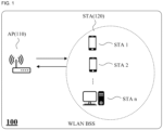
- FIG. 1 illustrates an example basic service set (BSS) in a wireless local area network (WLAN).
- a BSS may include one AP and at least one STA.
- FIG. 1 illustrates an example of a WLAN BSS 100 including a single AP 110 and a plurality of STAs 120.
- a single BSS includes a plurality of STAs. Any one of the plurality of STAs 120 receives resources allocated for wireless communication and communicates with the AP 110.
- the AP 110 delivers information regarding the resource allocation to the STA.
- FIG. 2 illustrates example resources used for WLAN communication.
- one rectangular block refers to a resource allocated to one STA.
- FIG. 2A illustrates Orthogonal Frequency Division Multiple (OFDM) used in the conventional IEEE 802.11.
- a conventional WLAN has a frame exchange performed in Time Division Multiple Access (TDMA).
- STAs share any one wireless frequency channel in ISM band. Only one user (STA) occupies a specific channel in a specific time period.
- TDMA Time Division Multiple Access
- FIG. 2B illustrates Orthogonal Frequency Division Multiple Access (OFDMA) modulation technology was employed newly in the IEEE 802.11ax.
- OFDMA Orthogonal Frequency Division Multiple Access
- one wireless channel can be composed of one or multiple resource units and the IEEE 802.11ax defines RU as a minimum allocation unit which is a group of subcarriers.
- the OFDMA enables multi-user transmission using frequency orthogonal division in the same time period. Any one user (STA) may use one RU in a specific time period.
- the AP may allocate different RUs to one or a plurality of STAs in a WLAN packet. Alternatively, the AP may separate spatial streams in a specific RU to allocate resources to any one or a plurality of STAs.
- the OFDMA provides more dynamic resource allocation to multiple users than the OFDM.
- FIG. 3 illustrates an example PHY PPDU packet format newly defined in 802.11ax.
- the PPDUs in FIG. 3 are as follows: HE SU PPDU; HE MU PPDU; HE ER SU PPDU; and HE TB PPDU.
- the formats are shown in FIG. 3 . Details of fields constituting each of the formats shown in FIG. 3 are shown in Table 1 below. Detailed descriptions of the fields will be omitted.
- the HE TB PPDU will be described below with reference to FIG. 8 .
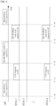
- FIG. 4 illustrates an example communication process between an AP and multiple STAs in 802.11ax.
- FIG. 4 illustrates an example communication process in a BSS in which there are a single AP and 'n' number of STAs. This example will be described in time order.
- FIG. 4 describes a multi-user (MU) scenario as an example.
- MU multi-user
- MU-RTS Multi-User Request-to-Send
- CTS Clear-to-Send
- the AP can perform the following steps.
- the MU-RTS/CTS exchange corresponds to a pre-operation for WLAN data transmission. This process is optional, and thus may not be an operation that must be performed before a DL MU PPDU.
- the AP transmits a frame including resource allocation information to solicited STAs.
- the DL MU PPDU may include a trigger frame or the DL MU PPDU may include a triggered response scheduling (TRS) control field.
- TRS triggered response scheduling
- the solicited STAs transmit the HE TB PPDU using allocated RU respectively.
- the AP may transmit a BlockAck frame in response to the reception of the HE TB PPDU. This kind of transmission of the BlockAck frame may be optional.
- the AP may communicate with a plurality of STAs.
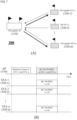
- FIG. 5 illustrates an example process of performing full-duplex communication in a WLAN environment.
- FIG. 5A illustrates a BSS 200 that performs full-duplex communication in a WLAN environment.
- the BSS 200 includes a single AP 210 and n number of STAs 220-1, 220-2,..., 220-n.
- the AP 210 is an AP capable of full-duplex communication (hereinafter referred to as an FD-capable AP).
- the FD-capable AP may be an AP having a function of cancelling self-interference (SI) caused by a signal transmitted by the AP itself.
- SI cancellation technology can be implemented in various ways.
- FIG. 5B illustrates an example for a full-duplex communication in the BSS 200. This example will be described in time order.
- the AP 210 transmits a reference frame to STA 1 220-1 and STA n 220-n.
- the reference frame may be the above-described trigger frame.
- the reference frame may include a TRS control field.
- the reference frame may include RU allocation information for OFDMA communication.
- solicited STA 1 220-1 and STA n 220-n transmit an HE TB PPDU through allocated RUs.
- STA 1 220-1 and STA n 220-n may transmit an HE TB PPDU to the AP in the same time period.
- STA 1 220-1 and STA n 220-n may transmit an HE TB PPDU at a certain timing on the basis of the received reference frame. That is, STA 1 220-1 and STA n 220-n may synchronize frames to be transmitted by using the timing of the received reference frame end.
- the AP 210 may transmit a certain frame to STA 2 220-2 at or within the same time period in which STA 1 220-1 and STA n 220-n transmit an HE TB PPDU.
- the frame transmitted from the AP 210 is represented as an HE TB FD PPDU. That is, the AP 210 transmits a frame to STA 2 220-2 while receiving frames from STA 1 220-1 and STA n 220-n in the same time period (full-duplex communication).
- a downlink constituting the full-duplex communication is represented by a thick solid line.
- the AP 210 synchronizes downlink and uplink and then performs downlink transmission.
- the AP 210 transmits an HE TB FD PPDU on the basis of the reference frame transmitted by the AP 210 or on the basis of timing information included in the reference frame.
- FIG. 6 illustrates another example process of performing full-duplex communication in a WLAN environment.
- FIG. 6 may be an example process of the BSS of FIG. 5A . This example will be described in time order.
- the AP can perform the following steps.
- the MU-RTS/CTS exchange corresponds to a pre-operation for MU transmission. This process is optional, and thus may not be an operation that must be performed before the DL MU PPDU.
- the DL MU PPDU corresponds to the above-described reference frame.
- the DL MU PPDU may include a TRS control field.
- the DL MU PPDU may include RU allocation information for STAs.
- STA 1 220-1 and STA n 220-n may transmit an HE TB PPDU to the AP in the same time period.
- STA 1 220-1 and STA n 220-n may transmit an HE TB PPDU at a certain timing which is the SIFS time boundary, after the end of a received reference frame. That is, STA 1 220-1 and STA n 220-n may synchronize frames to be transmitted by using the received DL MU PPDU.
- a SIFS is the time from the end of the last symbol, or signal extension if present, of the previous frame to the beginning of the first symbol of the preamble of the subsequent frame. For example, if the control frame is a response frame of a previous frame, the WLAN device transmits the control frame without performing backoff if a SIFS has elapsed.
- the transmission of the BlockAck frame may be optional.
- FIG. 7 is still another example process of performing full-duplex communication in a WLAN environment.
- FIG. 7A illustrates a BSS 300 that performs full-duplex communication in a WLAN environment.
- the BSS 300 includes a single AP 310 and n STAs 320-1, 320-2,..., 320-n.
- the AP 310 is an AP capable of full-duplex communication (hereinafter referred to as an FD-capable AP).
- the FD-capable AP may be an AP having a function of cancelling self-interference (SI) caused by a signal transmitted by the AP itself.
- STA 1 320-1 and STA n 320-n are STAs capable of full-duplex communication.
- the FD-capable STA may be an STA having a function of cancelling self-interference (SI) caused by a signal transmitted by the STA itself.
- SI cancellation technology can be implemented in various ways.
- FIG. 7B illustrates an example in which full-duplex communication is performed in the BSS 300. This example will be described in time order.
- the AP 310 transmits a reference frame to STA 1 320-1 and STA n 320-n.
- the reference frame may be the above-described trigger frame.
- the reference frame may include a TRS control field.
- the reference frame may include RU allocation information for OFDMA communication.
- STA 1 320-1 and STA n 320-n transmit an HE TB PPDU through allocated RUs.
- STA 1 320-1 and STA n 320-n may each transmit an HE TB PPDU to the AP in the same time period.
- STA 1 320-1 and STA n 320-n may transmit an HE TB PPDU at a certain timing on the basis of the received reference frame. That is, STA 1 320-1 and STA n 320-n may synchronize frames to be transmitted by using the received reference frame.
- the AP 310 may transmit an HE TB FD PPDU to STA 1 320-1 and STA n 320-n at or within a time period in which the HE TB PPDU is received (full-duplex communication).
- a downlink constituting the full-duplex communication is represented by a thick solid line.
- the AP 310 synchronizes downlink and uplink and then performs downlink transmission.
- the AP 310 transmits an HE TB FD PPDU on the basis of the reference frame transmitted by the AP 310 or on the basis of timing information included in the reference frame.
- the MU-RTS/CTS exchange may be performed before the reference frame is transmitted.
- the AP 310 may transmit a BlockAck frame in response to the reception of the HE TB PPDU.
- STA 1 320-1 and STA n 320-n may transmit an ACK for the HE TB FD PPDU.
- FIG. 8 is an example packet for full-duplex communication.
- An HE TB PPDU structure defined in IEEE 802.11ax is shown in an upper portion of FIG. 8 .
- An example HE TB FD PPDU structure is shown in a lower portion of FIG. 8 .
- An example in which the HE TB PPDU and the HE TB FD PPDU are placed in the same time period is shown.
- FIG. 8 is an example in which HE TB PPDU (uplink) and HE TB FD PPDU (downlink) constituting full-duplex communication are placed in the same time period.
- the HE TB PPDU may be transmitted in a certain time period on the basis of a reference frame (trigger framing) sent by AP.
- the HE TB PPDU may be transmitted after a short IFS (SIFS) time interval from the reference frame end.
- SIFS refers to the shortest one among inter-packet space time intervals between consecutive two packets defined in the standard.
- the HE TB PPDU can be divided into a non-HE portion and an HE portion.
- the non-HE portion includes a L-short training field (STF), L-long training field (LTF), and L-signal information field (SIG). These fields are defined in a conventional WLAN standard. 802.11ax uses the same fields as described in the WLAN standard for the purpose of compatibility with conventional WLAN.
- the L-STF is a short training sequence and is used for packet detection and automatic gain adjustment (AGC).
- the L-LTF is a relatively long training sequence and is used for channel estimation.
- the L-SIG may include control information corresponding to decoding of PSDU or the like.
- RL-SIG in which a conventional legacy L-SIG is repeated, is a field for HE PPDU detection.
- HE-SIG-A includes MCS, a frequency bandwidth, the number of spatial streams (NSTS), and parameters for frame decoding.
- HE-STF and HE-LTF include a training sequence for multiple-input and multiple-output (MIMO).
- MIMO multiple-input and multiple-output
- the HE-STF is mainly used to measure automatic gain adjustment during MIMO transmission.
- the HE-LTF is used to estimate a MIMO channel.
- the HE-LTF has a variable length.
- Data field includes an encoder/decoder scrambler and an encoded MAC frame.
- PE is an extension field.
- the HE TB PPDU can be divided into a pre-HE modulated field and an HE modulated field.
- HE PHY can support DFT periods of 3.2 ⁇ s and 12.8 ⁇ s for the pre-HE modulated field and the HE modulated filed of the HE PPDU, respectively.
- a modulated signal may be transmitted in a region in which the HE modulated field of the HE TB PPDU is started in the same time period.
- the HE TB FD PPDU may be aligned to the HE modulated field of the HE TB PPDU in the same time period.
- a null portion may be a signal field in which no signal is transmitted. Also, the null portion may be a signal field for transmitting information that does not affect the demodulation processing of the HE TB PPDU by the AP.
- the HE TB FD PPDU may be transmitted in a time period in which the AP receives the HE TB PPDU, and the HE TB FD PPDU is intended to be transmitted in a period that does not affect the processing of the received HE TB PPDU. That is, the AP controls a time to transmit the HE TB FD PPDU such that the transmission of the HE TB FD PPDU does not disturb the transmission of the HE TB PPDU. The AP ensures that the training process for the received HE TB PPDU is normally performed.
- FIG. 8 A lower portion of FIG. 8 illustrates an HE TB FD PPDU structure.
- the HE TB FD PPDU structure shown in FIG. 8 is an example, and the HE TB FD PPDU may have another structure.
- FIG. 8 illustrates an example including FD-STF, FD-LTF, FD-SIG, and the like. In this case, the fields may perform functions similar to those of the HE-STF, HE-LTF, and HE-SIG.
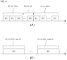
- FIG. 9 illustrates example resources to be allocated for full-duplex communication.
- FIG. 9A illustrates an example in which individual RUs are allocated to uplink and downlink. As described in FIG. 5 , when an FD-capable AP performs full-duplex communication with any STA, the AP and the STA may use different RUs.
- FIG. 9B illustrates an example in which a common RU is allocated to uplink and downlink.
- FIG. 9B illustrates a case in which a pair of AP and STA uses a single common RU.
- the AP may deliver information regarding the RU through the reference frame (the trigger frame).
- FIG. 9B illustrates an example in which the AP of FIG. 7 and STA 1 use a common RU and the AP of FIG. 7 and STA n use a common RU.
- FIG. 10 illustrates an example of resource allocation for full-duplex communication.
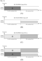
- FIG. 10 illustrates an example in which an AP receives an HE TB PPDU from two STAs (STA 1 and STA n) at a specific time and transmits an HE TB FD PPDU to an STA (STA1, STA n, or another STA) at the same specific time.
- FIG. 10 illustrates a 40-MHz band, as an example.
- FIG. 10A illustrates an example of resource allocation for the HE TB PPDU transmitted by STA 1.
- FIG. 10B illustrates an example of resource allocation for the HE TB FD PPDU transmitted by the AP. In the HE TB FD PPDU, a signal is transmitted only in the HE modulated field as described above.
- FIG. 10C illustrates an example of resource allocation for the HE TB PPDU transmitted by STA n.
- FIG. 10D illustrates an example in which resources are allocated to frames transmitted by STA 1, STA n, and the AP in the same time period. Referring to FIG. 10 , it shows that three individual frames may be simultaneously transmitted on two channels of 20 MHz.
- a pre-HE modulated field is generally transmitted at corresponding 20 MHz (indicated by 1 and 2 in FIG. 10 ). However, in some cases, the pre-HE modulated field may be transmitted at 40 MHz including a corresponding 20 MHz channel (not shown).
- FIG. 11 illustrates an example reference frame.
- the reference frame may be a trigger frame defined in IEEE 802.11ax.
- the reference frame may include information regarding RUs for full-duplex communication (FD). Resource allocation information for the FD communication may be implemented in various ways.
- FIG. 11 illustrates an example frame to be used in 802.11ax. A description of information included in a MAC header, that is, a description of the same part as a conventional WLAN header will be omitted.
- HT Control includes an aggregated control subfield.
- a part (A) indicates an example in which a field for FD resource information is separately added to the control subfield.
- the part (A) includes Control ID, FD, and Reserved field.
- Control ID is an identifier about information indicated by the control subfield.
- FD field may include resource information for the FD communication.
- a part (B) indicates another example control subfield.
- the resource information for the FD may be included in Control Information field.
- Control ID is a specific value to which any current use is not allocated
- the resource information for the FD feature may be included in Control Information field.
- FIG. 11 illustrates an example in which the FD resource information is conveyed using HT Control field.
- the reference frame may convey the FD resource information through another field or an FD-dedicated field.
- FIG. 12 illustrates an example block diagram of an AP and an STA.
- FIG. 12 illustrates a BSS including a single AP 410 and a single STA 420, as an example. It is assumed that the AP 410 and the STA 420 are FD-capable apparatuses.
- the AP 410 includes a storage device 411, a memory 412, a computing device 413, and a communication device 414.
- the storage device 411, the memory 412, the computing device 413, and the communication device 414 are shown as separate independent elements. At least any combination merged with two or more components among the storage device, the memory, the computing device and the communication device 414 may be configured in an integrated manner.
- the storage device 411 stores a source code or program for WLAN communication with the STA.
- the storage device 411 stores information for high-efficiency WLAN communication by default. Also, the storage device 411 may store information for the above-described full-duplex communication.
- the storage device 411 may be implemented in the form of a hard disk, a read-only memory (ROM), a flash memory, or the like.
- the storage device 411 may store data to be transmitted and data received.
- the memory 412 may temporarily store data generated while the AP 410 performs communication.
- the communication device 414 refers to an element for transmitting and receiving data through WLAN communication.
- the communication device 414 may include at least one antenna and a communication module.
- the communication device 414 may include a plurality of antennas for MIMO.
- the communication device 414 may receive packets from at least one STA. Also, the communication device 414 may transmit packets to at least one STA.
- the communication device 414 may receive program update information from an external object.
- the computing device 413 may transmit and receive data (packets) using a program stored in the storage device 411.
- the computing device 413 may transmit a reference frame to at least one STA through the communication device 414 according to a received command or a generated command.
- the communication device 414 may receive an uplink frame from an STA in a specific time period determined on the basis of the reference frame.
- the computing device 413 may transmit a downlink frame to an STA through the communication device 414 in a part time of the time period in which the downlink frame is received. In this case, the computing device 413 may transmit a downlink frame to the STA having transmitted the uplink or another STA.
- the computing device 413 may perform control such that the downlink frame is transmitted to an HE modulated field of an uplink frame.
- the computing device 413 may be a device for processing data and performing certain computation, such as a processor, an AP, and a chip with an embedded program.
- the AP 410 may transmit the DL MU PPDU to the STA 420.
- the AP 410 may receive the HE TB PPDU from the STA 420 in a specific time period.
- the AP 410 may transmit the HE TB FD PPDU to the STA 420 or another STA in a period in which an HE TB PPDU HE modulated field is transmitted.
- the AP 410 may include an element for cancelling SI to perform full-duplex communication.
- the STA 420 includes a storage device 421, a memory 422, a computing device 423, an interface device 424, and a communication device 425.
- the storage device 421, the memory 422, the computing device 423, the interface device 424, and the communication device 425 are shown as separate independent elements. At least any combination merged with two or more components among the storage device 421, the memory 422, the computing device 423, the interface device 424 and the communication device 425 may be configured in an integrated manner.
- the storage device 421 stores a source code or program for WLAN communication with the AP.
- the storage device 421 stores information for high-efficiency WLAN communication by default. Also, the storage device 421 may store information for the above-described full-duplex communication.
- the storage device 421 may be implemented in the form of a hard disk, a ROM, a flash memory, or the like.
- the storage device 421 may store data to be transmitted and data received.
- the memory 422 may temporarily store data generated while the STA 420 performs communication.
- the interface device 424 is a device for receiving certain commands or data from the outside.
- the interface device 424 may receive certain commands or data from an external storage device or an input device that is physically connected to the interface device 424.
- the interface device 424 may receive a command for communication with the AP 410, control information, data to be transmitted, or the like.
- the communication device 425 refers to an element for transmitting and receiving data through WLAN communication.
- the communication device 425 may include at least one antenna and a communication module.
- the communication device 425 may include a plurality of antennas for MIMO.
- the communication device 425 may receive packets from the AP. Also, the communication device 425 may transmit packets to the AP.
- the communication device 425 may receive program update information from an external object.
- the computing device 423 may transmit and receive data (packets) using a program stored in the storage device 421.
- the communication device 425 may receive a reference frame from the AP 410.
- the computing device 423 may determine a specific time period on the time basis of the reference frame.
- the computing device 423 may transmit an uplink frame to the AP through the communication device 425 in the determined specific time period.
- the computing device 423 may be a device for processing data and performing certain computation, such as a processor, an AP, and a chip with an embedded program.
- the communication device 425 may receive a downlink frame from the AP 410 in a part time of the period in which the uplink frame is transmitted.
- the downlink frame may be received in a region where an HE modulated field of the uplink frame is placed.
- the computing device 423 may control the communication device 425 such that the downlink frame is received at the same time as the uplink frame is transmitted.
- the STA 420 may receive the DL MU PPDU from the AP 410.
- the STA 420 may transmit the HE TB PPDU in a specific time period on the basis of the DL MU PPDU.
- the STA 420 may receive the HE TB FD PPDU from the AP 410 while transmitting the HE TB PPDU.
- the HE TB FD PPDU may be received in a period in which the HE modulated field of the HE TB PPDU is transmitted.
- the STA 420 may include an element for cancelling SI to perform full-duplex communication.
- full-duplex communication method may be implemented using a program (or application) including an executable algorithm that may be executed by a computer.
- the full-duplex communication method may be embedded into an AP and an STA.
- the program may be stored and provided in a non-transitory computer readable medium.
- the non-transitory computer readable medium refers not to a medium that temporarily stores data such as a register, a cache, and a memory but to a medium that semi-permanently stores data and that is readable by a device.
- the above-described various applications or programs may be provided while being stored in a non-transitory computer readable medium such as a compact disc (CD), a digital versatile disc (DVD), a hard disk, a Blu-ray disc, a Universal Serial Bus (USB), a memory card, a read-only memory (ROM), etc.
Landscapes
- Engineering & Computer Science (AREA)
- Signal Processing (AREA)
- Computer Networks & Wireless Communication (AREA)
- Mobile Radio Communication Systems (AREA)
Description
- The following description relates to a technique for performing in-band full-duplex communication in a high-efficiency wireless local area network (WLAN).
- In a wireless local area network (WLAN), a single basic service set (BSS) is composed of two kinds of entities which are a single AP Station (STA) and multiple non-AP STAs. STAs share a same radio frequency channel with one out of WLAN operation bandwidth options (e.g.20/40/80/160MHz). Here, AP STA and non-AP STA could be referred as AP and STA, respectively.
- the legacy IEEE 802.11a/b/g/n/ac standard does not guarantee communication stability in dense environments with many users. In order to overcome this limit, the High-Efficiency WLAN Study Group (HEW SG) and the IEEE Task Group ax (TGax) were formed by IEEE 802.11 working group, which has worked on the standardization of IEEE 802.11ax as the next generation WLAN standard in 2019. The IEEE 802.11ax standard aims to improve system throughput in dense environments with many APs and STAs.
US 2017/055284 A1 discloses a full duplex mechanism to improve spectral efficiency of wireless communication systems such as 802.11ax. -
EP 3 188 429 A1 - Full-duplex (FD) communication is one of promising next-generation wireless technologies. This technology enables up to double network throughput ideally because the information can be transmitted and received between wireless communication nodes through the same channel at the same time. In recent FD communication becomes more feasible thanks to the enhancement of self-interference cancellation (SIC) technology.
- The following description is intended to provide full-duplex communication between an AP and an STA in an IEEE 802.11ax environment.
- The invention is defined by the independent claims. Embodiments are defined by dependent claims.
- The following description enables full-duplex communication in the IEEE 802.11ax environment while maintaining backward compatibility with the IEEE 802.11 standards (802.11a/b/g/n/ac/ax). The following description provides a communication protocol for avoiding interference between an uplink signal and a downlink signal that are carried through the same channel at the same time in IEEE 802.11ax.
-
-
FIG. 1 illustrates an example of a basic service set in a wireless local area network (WLAN). -
FIG. 2 illustrates example resources used for WLAN communication. -
FIG. 3 illustrates an example PHY PPDU packet format defined in 802.11ax. -
FIG. 4 illustrates an example communication process between an access point (AP) and a station (STA) in 802.11ax. -
FIG. 5 illustrates an example process of performing full-duplex communication in a WLAN environment. -
FIG. 6 illustrates another example process of performing full-duplex communication in a WLAN environment. -
FIG. 7 illustrates still another example process of performing full-duplex communication in a WLAN environment. -
FIG. 8 illustrates an example packet for full-duplex communication. -
FIG. 9 illustrates example resources to be allocated for full-duplex communication. -
FIG. 10 illustrates example resource allocation for full-duplex communication. -
FIG. 11 illustrates an example reference frame. -
FIG. 12 illustrates an example block diagram of an AP and an STA. - Throughout the drawings and the detailed description, unless otherwise described, the same drawing reference numerals will be understood to refer to the same elements, features, and structures. The relative size and depiction of these elements may be exaggerated for clarity, illustration, and convenience
- The following detailed description is provided to assist the reader in gaining a comprehensive understanding of the methods, apparatuses, and/or systems described herein. Accordingly, various changes, modifications, and equivalents of the systems, apparatuses and/or methods described herein will be suggested to those of ordinary skill in the art. Also, descriptions of well-known functions and constructions may be omitted for increased clarity and conciseness.
- The presently described examples will be understood by reference to the drawings, wherein like parts are designated by like numerals throughout. The drawings are not necessarily drawn to scale, and the size and relative sizes of the layers and regions may have been exaggerated for clarity.
- It will be understood that, although the terms first, second, A, B, etc. may be used herein to describe various elements, these elements should not be limited by these terms. These terms are only used to distinguish one element from another. For example, a first element could be termed a second element, and, similarly, a second element could be termed a first element, without departing from the scope of the present invention. As used herein, the term "and/or" includes any and all combinations of one or more of the associated listed items.
- As used herein, the singular forms "a," "an" and "the" are intended to include the plural forms as well, unless the context clearly indicates otherwise. It will be further understood that the terms "comprises," "comprising," "includes" and/or "including," when used herein, specify the presence of stated features, integers, steps, operations, elements, and/or components, but do not preclude the presence or addition of one or more other features, integers, steps, operations, elements, components, and/or groups thereof.
- Before starting detailed explanations of figures, components that will be described in the specification are discriminated merely according to functions mainly performed by the components or conventionally carried out according to common knowledge of related technical fields. That is, two or more components which will be described later can be integrated into a single component. Furthermore, a single component which will be explained later can be separated into two or more components. Moreover, each component which will be described can additionally perform some or all of a function executed by another component in addition to the main function thereof. Some or all of the main function of each component which will be explained can be carried out by another component. Accordingly, presence/absence of each component which will be described throughout the specification should be functionally interpreted.
- The following description applies to a wireless local area network (WLAN). The following description may apply to the next generation WLAN method (IEEE 802.11ax) or the like. The IEEE 802.11ax maintains compatibility with the conventional IEEE 802.11a/b/g/n/ac. The following description may be executed in the IEEE 802.11ax environment, and also maintains compatibility with the conventional IEEE 802.11a/b/g/n/ac.
- The following description relates to in-band full-duplex communication. The following description may basically apply to the IEEE 802.11ax. However, the following description does not necessarily limitedly apply to the IEEE 802.11ax. Therefore, the following description may apply to WLAN standards that will emerge after the IEEE 802.11ax.
- Terms used herein will be defined.
- A WLAN or a next generation WLAN basically refers to a communication network operating according to a protocol defined in the IEEE 802.11ax. A conventional WLAN refers to a WLAN according to a standard prior to the IEEE 802.11ax.
- An access point (AP) is an apparatus that provides access to the distribution system services and mostly is connected to the Internet to provide a wireless channel in a certain coverage area. The apparatus is hereinafter referred to as an AP station or an AP.
- A non-AP station (STA) is an apparatus that communicates the information through a certain wireless channel allocated by an AP. The apparatus is hereinafter referred to as a station or an STA.
- A signal transmitted by an AP to an STA is called a downlink signal. The downlink signal may be composed of at least one frame. The frame included in the downlink signal is called a downlink frame.
- A signal transmitted by an STA to an AP is called an uplink signal. The uplink signal may be composed of at least one frame. The frame included in the uplink signal is called an uplink frame.
- The full-duplex communication basically refers to in-band full-duplex transmission and reception concurrently using the same channel.
- The IEEE 802.11ax is well known as High Efficiency WLAN (HE WLAN). A Physical Protocol Data Unit (PPDU) is newly defined in the IEEE 802.11ax PHY. Examples of the PHY PPDU for data transmission include High Efficiency Single User Physical Protocol Data Unit (HE SU PPDU), High Efficiency Multi User Physical Protocol Data Unit (HE MU PPDU), High Efficiency extended range Single User Physical Protocol Data Unit (HE ER SU PPDU) and High Efficiency Trigger Based Physical Protocol Data Unit (HE TB PPDU).
- First, the WLAN and the IEEE 802.11ax will be described briefly below.
-
FIG. 1 illustrates an example basic service set (BSS) in a wireless local area network (WLAN). A BSS may include one AP and at least one STA.FIG. 1 illustrates an example of aWLAN BSS 100 including asingle AP 110 and a plurality ofSTAs 120. For convenience of description, it is assumed that a single BSS includes a plurality of STAs. Any one of the plurality ofSTAs 120 receives resources allocated for wireless communication and communicates with theAP 110. TheAP 110 delivers information regarding the resource allocation to the STA. -
FIG. 2 illustrates example resources used for WLAN communication. InFIG. 2 , one rectangular block refers to a resource allocated to one STA. -
FIG. 2A illustrates Orthogonal Frequency Division Multiple (OFDM) used in the conventional IEEE 802.11. A conventional WLAN has a frame exchange performed in Time Division Multiple Access (TDMA). STAs share any one wireless frequency channel in ISM band. Only one user (STA) occupies a specific channel in a specific time period. -
FIG. 2B illustrates Orthogonal Frequency Division Multiple Access (OFDMA) modulation technology was employed newly in the IEEE 802.11ax. In OFDMA, one wireless channel can be composed of one or multiple resource units and the IEEE 802.11ax defines RU as a minimum allocation unit which is a group of subcarriers. The OFDMA enables multi-user transmission using frequency orthogonal division in the same time period. Any one user (STA) may use one RU in a specific time period. The AP may allocate different RUs to one or a plurality of STAs in a WLAN packet. Alternatively, the AP may separate spatial streams in a specific RU to allocate resources to any one or a plurality of STAs. The OFDMA provides more dynamic resource allocation to multiple users than the OFDM. -
FIG. 3 illustrates an example PHY PPDU packet format newly defined in 802.11ax. The PPDUs inFIG. 3 are as follows: HE SU PPDU; HE MU PPDU; HE ER SU PPDU; and HE TB PPDU. The formats are shown inFIG. 3 . Details of fields constituting each of the formats shown inFIG. 3 are shown in Table 1 below. Detailed descriptions of the fields will be omitted. The HE TB PPDU will be described below with reference toFIG. 8 .[Table 1] Field Description L-STF Non-HT Short Training field L-LTF Non-HT Long Training field L-SIG Non-HT SIGNAL field RL-SIG Repeated Non-HT SIGNAL field HE-SIG-A HE SIGNAL A field HE-SIG-B HE SIGNAL B field HE-STF HE Short Training field HE-LTF HE Long Training field Data The Data field carrying the PSDU(s) PE Packet -
FIG. 4 illustrates an example communication process between an AP and multiple STAs in 802.11ax.FIG. 4 illustrates an example communication process in a BSS in which there are a single AP and 'n' number of STAs. This example will be described in time order.FIG. 4 describes a multi-user (MU) scenario as an example. - The AP transmits a Multi-User Request-to-Send (MU-RTS) frame to
STA 1 and STA n at time T = t0. In response to the MU-RTS frame,STA 1 and STA n commence a Clear-to-Send (CTS) frame at time T = t1. After receiving the CTS response successfully, the AP can perform the following steps. The MU-RTS/CTS exchange corresponds to a pre-operation for WLAN data transmission. This process is optional, and thus may not be an operation that must be performed before a DL MU PPDU. - The AP transmits a frame including resource allocation information to solicited STAs. The AP transmits a DL MU PPDU to solicited STAs, herein,
STA 1 and STA n at time T = t2. The DL MU PPDU may include a trigger frame or the DL MU PPDU may include a triggered response scheduling (TRS) control field. In response to the DL MU PPDU,STA 1 and STA n transmit an HE TB PPDU at time T = t3 as a response frame along with an ACK. The solicited STAs transmit the HE TB PPDU using allocated RU respectively. - The AP may transmit a BlockAck frame in response to the reception of the HE TB PPDU. This kind of transmission of the BlockAck frame may be optional.
- By repeating the above communication process, the AP may communicate with a plurality of STAs.
- Full-duplex communication applicable to a WLAN environment such as 802.11ax will be described below. It is assumed that an AP and STA which will be mentioned support IEEE 802.11ax.
-
FIG. 5 illustrates an example process of performing full-duplex communication in a WLAN environment.FIG. 5A illustrates aBSS 200 that performs full-duplex communication in a WLAN environment. TheBSS 200 includes asingle AP 210 and n number of STAs 220-1, 220-2,..., 220-n. TheAP 210 is an AP capable of full-duplex communication (hereinafter referred to as an FD-capable AP). The FD-capable AP may be an AP having a function of cancelling self-interference (SI) caused by a signal transmitted by the AP itself. The SI cancellation technology can be implemented in various ways. -
FIG. 5B illustrates an example for a full-duplex communication in theBSS 200. This example will be described in time order. TheAP 210 transmits a reference frame toSTA 1 220-1 and STA n 220-n. The reference frame may be the above-described trigger frame. Also, the reference frame may include a TRS control field. The reference frame may include RU allocation information for OFDMA communication. - When the reference frame is received, solicited
STA 1 220-1 and STA n 220-n transmit an HE TB PPDU through allocated RUs.STA 1 220-1 and STA n 220-n may transmit an HE TB PPDU to the AP in the same time period.STA 1 220-1 and STA n 220-n may transmit an HE TB PPDU at a certain timing on the basis of the received reference frame. That is,STA 1 220-1 and STA n 220-n may synchronize frames to be transmitted by using the timing of the received reference frame end. - Meanwhile, the
AP 210 may transmit a certain frame toSTA 2 220-2 at or within the same time period in whichSTA 1 220-1 and STA n 220-n transmit an HE TB PPDU. Herein the frame transmitted from theAP 210 is represented as an HE TB FD PPDU. That is, theAP 210 transmits a frame toSTA 2 220-2 while receiving frames fromSTA 1 220-1 and STA n 220-n in the same time period (full-duplex communication). InFIG. 5A , a downlink constituting the full-duplex communication is represented by a thick solid line. TheAP 210 synchronizes downlink and uplink and then performs downlink transmission. TheAP 210 transmits an HE TB FD PPDU on the basis of the reference frame transmitted by theAP 210 or on the basis of timing information included in the reference frame. -
FIG. 6 illustrates another example process of performing full-duplex communication in a WLAN environment.FIG. 6 may be an example process of the BSS ofFIG. 5A . This example will be described in time order. - The
AP 210 transmits an MU-RTS frame toSTA 1 220-1 and STA n 220-n at time T = t0. In response to the MU-RTS frame,STA 1 220-1 and STA n 220-n commence the transmission of a CTS frame at time T = t1 respectively in OFDMA modulation way. After receiving the CTS response, the AP can perform the following steps. The MU-RTS/CTS exchange corresponds to a pre-operation for MU transmission. This process is optional, and thus may not be an operation that must be performed before the DL MU PPDU. - The
AP 210 transmits the DL MU PPDU toSTA 1 220-1 and STA n 220-n at time T = t2. The DL MU PPDU corresponds to the above-described reference frame. The DL MU PPDU may include a TRS control field. The DL MU PPDU may include RU allocation information for STAs.
When the reference frame is received,STA 1 220-1 and STA n 220-n may transmit an HE TB PPDU through allocated RUs along with an ACK at time T = t3.STA 1 220-1 and STA n 220-n may transmit an HE TB PPDU to the AP in the same time period.STA 1 220-1 and STA n 220-n may transmit an HE TB PPDU at a certain timing which is the SIFS time boundary, after the end of a received reference frame. That is,STA 1 220-1 and STA n 220-n may synchronize frames to be transmitted by using the received DL MU PPDU. A SIFS is the time from the end of the last symbol, or signal extension if present, of the previous frame to the beginning of the first symbol of the preamble of the subsequent frame. For example, if the control frame is a response frame of a previous frame, the WLAN device transmits the control frame without performing backoff if a SIFS has elapsed. - Meanwhile, the
AP 210 may transmit an HE TB FD PPDU toSTA 2 220-2 at time T = t3. That is, theAP 210 transmits a frame toSTA 2 220-2 while receiving frames fromSTA 1 220-1 and STA n 220-n in the same time period (full-duplex communication). TheAP 210 transmits an HE TB FD PPDU on the basis of the DL MU PPDU transmitted by theAP 210 or on the basis of timing information included in the DL MU PPDU. Referring toFIG. 6 , a null portion are shown in front of the HE TB FD PPDU at time T = t3. This will be described withFIG. 8 . - In response to the reception of the HE TB PPDU, the
AP 210 may transmit a BlockAck frame toSTA 1 220-1 and STA n 220-n at time T = t4. The transmission of the BlockAck frame may be optional. Also, at time T = t4,STA 2 220-2 may transmit an ACK for the HE TB FD PPDU corresponding to time T = t3. -
FIG. 7 is still another example process of performing full-duplex communication in a WLAN environment.FIG. 7A illustrates aBSS 300 that performs full-duplex communication in a WLAN environment. TheBSS 300 includes asingle AP 310 and n STAs 320-1, 320-2,..., 320-n. TheAP 310 is an AP capable of full-duplex communication (hereinafter referred to as an FD-capable AP). The FD-capable AP may be an AP having a function of cancelling self-interference (SI) caused by a signal transmitted by the AP itself.STA 1 320-1 and STA n 320-n are STAs capable of full-duplex communication. The FD-capable STA may be an STA having a function of cancelling self-interference (SI) caused by a signal transmitted by the STA itself. The SI cancellation technology can be implemented in various ways. -
FIG. 7B illustrates an example in which full-duplex communication is performed in theBSS 300. This example will be described in time order. TheAP 310 transmits a reference frame toSTA 1 320-1 and STA n 320-n. The reference frame may be the above-described trigger frame. Also, the reference frame may include a TRS control field. The reference frame may include RU allocation information for OFDMA communication. - When the reference frame is received,
STA 1 320-1 and STA n 320-n transmit an HE TB PPDU through allocated RUs.STA 1 320-1 and STA n 320-n may each transmit an HE TB PPDU to the AP in the same time period.STA 1 320-1 and STA n 320-n may transmit an HE TB PPDU at a certain timing on the basis of the received reference frame. That is,STA 1 320-1 and STA n 320-n may synchronize frames to be transmitted by using the received reference frame. - Meanwhile, the
AP 310 may transmit an HE TB FD PPDU toSTA 1 320-1 and STA n 320-n at or within a time period in which the HE TB PPDU is received (full-duplex communication). InFIG. 7A , a downlink constituting the full-duplex communication is represented by a thick solid line. TheAP 310 synchronizes downlink and uplink and then performs downlink transmission. TheAP 310 transmits an HE TB FD PPDU on the basis of the reference frame transmitted by theAP 310 or on the basis of timing information included in the reference frame. - Similarly, to
FIG. 6 , although not shown inFIG. 7B , the MU-RTS/CTS exchange may be performed before the reference frame is transmitted. Also, after the HE TB FD PPDU is transmitted, theAP 310 may transmit a BlockAck frame in response to the reception of the HE TB PPDU. Also,STA 1 320-1 and STA n 320-n may transmit an ACK for the HE TB FD PPDU. -
FIG. 8 is an example packet for full-duplex communication. An HE TB PPDU structure defined in IEEE 802.11ax is shown in an upper portion ofFIG. 8 . An example HE TB FD PPDU structure is shown in a lower portion ofFIG. 8 . An example in which the HE TB PPDU and the HE TB FD PPDU are placed in the same time period is shown.FIG. 8 is an example in which HE TB PPDU (uplink) and HE TB FD PPDU (downlink) constituting full-duplex communication are placed in the same time period. - As described above, the HE TB PPDU may be transmitted in a certain time period on the basis of a reference frame (trigger framing) sent by AP. In this case, the HE TB PPDU may be transmitted after a short IFS (SIFS) time interval from the reference frame end. The SIFS refers to the shortest one among inter-packet space time intervals between consecutive two packets defined in the standard.
- The HE TB PPDU can be divided into a non-HE portion and an HE portion. The non-HE portion includes a L-short training field (STF), L-long training field (LTF), and L-signal information field (SIG). These fields are defined in a conventional WLAN standard. 802.11ax uses the same fields as described in the WLAN standard for the purpose of compatibility with conventional WLAN. The L-STF is a short training sequence and is used for packet detection and automatic gain adjustment (AGC). The L-LTF is a relatively long training sequence and is used for channel estimation. The L-SIG may include control information corresponding to decoding of PSDU or the like.
- RL-SIG, in which a conventional legacy L-SIG is repeated, is a field for HE PPDU detection. HE-SIG-A includes MCS, a frequency bandwidth, the number of spatial streams (NSTS), and parameters for frame decoding. HE-STF and HE-LTF include a training sequence for multiple-input and multiple-output (MIMO). The HE-STF is mainly used to measure automatic gain adjustment during MIMO transmission. The HE-LTF is used to estimate a MIMO channel. The HE-LTF has a variable length. Data field includes an encoder/decoder scrambler and an encoded MAC frame. PE is an extension field.
- The HE TB PPDU can be divided into a pre-HE modulated field and an HE modulated field. HE PHY can support DFT periods of 3.2 µs and 12.8 µs for the pre-HE modulated field and the HE modulated filed of the HE PPDU, respectively.
- In the HE TB FD PPDU, a modulated signal may be transmitted in a region in which the HE modulated field of the HE TB PPDU is started in the same time period. The HE TB FD PPDU may be aligned to the HE modulated field of the HE TB PPDU in the same time period. A null portion may be a signal field in which no signal is transmitted. Also, the null portion may be a signal field for transmitting information that does not affect the demodulation processing of the HE TB PPDU by the AP. The HE TB FD PPDU may be transmitted in a time period in which the AP receives the HE TB PPDU, and the HE TB FD PPDU is intended to be transmitted in a period that does not affect the processing of the received HE TB PPDU. That is, the AP controls a time to transmit the HE TB FD PPDU such that the transmission of the HE TB FD PPDU does not disturb the transmission of the HE TB PPDU. The AP ensures that the training process for the received HE TB PPDU is normally performed.
- A lower portion of
FIG. 8 illustrates an HE TB FD PPDU structure. The HE TB FD PPDU structure shown inFIG. 8 is an example, and the HE TB FD PPDU may have another structure.FIG. 8 illustrates an example including FD-STF, FD-LTF, FD-SIG, and the like. In this case, the fields may perform functions similar to those of the HE-STF, HE-LTF, and HE-SIG. -
FIG. 9 illustrates example resources to be allocated for full-duplex communication.FIG. 9A illustrates an example in which individual RUs are allocated to uplink and downlink. As described inFIG. 5 , when an FD-capable AP performs full-duplex communication with any STA, the AP and the STA may use different RUs. -
FIG. 9B illustrates an example in which a common RU is allocated to uplink and downlink.FIG. 9B illustrates a case in which a pair of AP and STA uses a single common RU. As shown inFIG. 7 , when an FD-capable AP and an FD-capable STA perform full-duplex communication, the pair may use a common RU. The AP may deliver information regarding the RU through the reference frame (the trigger frame).FIG. 9B illustrates an example in which the AP ofFIG. 7 andSTA 1 use a common RU and the AP ofFIG. 7 and STA n use a common RU. -
FIG. 10 illustrates an example of resource allocation for full-duplex communication.FIG. 10 illustrates an example in which an AP receives an HE TB PPDU from two STAs (STA 1 and STA n) at a specific time and transmits an HE TB FD PPDU to an STA (STA1, STA n, or another STA) at the same specific time.FIG. 10 illustrates a 40-MHz band, as an example. -
FIG. 10A illustrates an example of resource allocation for the HE TB PPDU transmitted bySTA 1.FIG. 10B illustrates an example of resource allocation for the HE TB FD PPDU transmitted by the AP. In the HE TB FD PPDU, a signal is transmitted only in the HE modulated field as described above.FIG. 10C illustrates an example of resource allocation for the HE TB PPDU transmitted by STA n.FIG. 10D illustrates an example in which resources are allocated to frames transmitted bySTA 1, STA n, and the AP in the same time period. Referring toFIG. 10 , it shows that three individual frames may be simultaneously transmitted on two channels of 20 MHz. - When 242-tone RU (20 MHz) or less-tone RU is allocated, a pre-HE modulated field is generally transmitted at corresponding 20 MHz (indicated by ① and ② in
FIG. 10 ). However, in some cases, the pre-HE modulated field may be transmitted at 40 MHz including a corresponding 20 MHz channel (not shown). -
FIG. 11 illustrates an example reference frame. The reference frame may be a trigger frame defined in IEEE 802.11ax. The reference frame may include information regarding RUs for full-duplex communication (FD). Resource allocation information for the FD communication may be implemented in various ways.FIG. 11 illustrates an example frame to be used in 802.11ax. A description of information included in a MAC header, that is, a description of the same part as a conventional WLAN header will be omitted. - HT Control includes an aggregated control subfield. In
FIG. 11 , a part (A) indicates an example in which a field for FD resource information is separately added to the control subfield. The part (A) includes Control ID, FD, and Reserved field. Control ID is an identifier about information indicated by the control subfield. When Control ID is configured to set a value indicating FD resource information, FD field may include resource information for the FD communication. InFIG. 11 , a part (B) indicates another example control subfield. In the part (B), when Control ID is configured to set a value indicating FD resource information, the resource information for the FD may be included in Control Information field. Alternatively, when Control ID is a specific value to which any current use is not allocated, the resource information for the FD feature may be included in Control Information field. -
FIG. 11 illustrates an example in which the FD resource information is conveyed using HT Control field. In some cases, the reference frame may convey the FD resource information through another field or an FD-dedicated field. -
FIG. 12 illustrates an example block diagram of an AP and an STA.FIG. 12 illustrates a BSS including asingle AP 410 and asingle STA 420, as an example. It is assumed that theAP 410 and theSTA 420 are FD-capable apparatuses. - The
AP 410 includes astorage device 411, amemory 412, a computing device 413, and acommunication device 414. InFIG. 12 , thestorage device 411, thememory 412, the computing device 413, and thecommunication device 414 are shown as separate independent elements. At least any combination merged with two or more components among the storage device, the memory, the computing device and thecommunication device 414 may be configured in an integrated manner. - The
storage device 411 stores a source code or program for WLAN communication with the STA. Thestorage device 411 stores information for high-efficiency WLAN communication by default. Also, thestorage device 411 may store information for the above-described full-duplex communication. Thestorage device 411 may be implemented in the form of a hard disk, a read-only memory (ROM), a flash memory, or the like. Thestorage device 411 may store data to be transmitted and data received. - The
memory 412 may temporarily store data generated while theAP 410 performs communication. - The
communication device 414 refers to an element for transmitting and receiving data through WLAN communication. Thecommunication device 414 may include at least one antenna and a communication module. Thecommunication device 414 may include a plurality of antennas for MIMO. Thecommunication device 414 may receive packets from at least one STA. Also, thecommunication device 414 may transmit packets to at least one STA. Thecommunication device 414 may receive program update information from an external object. - The computing device 413 may transmit and receive data (packets) using a program stored in the
storage device 411. The computing device 413 may transmit a reference frame to at least one STA through thecommunication device 414 according to a received command or a generated command. Thecommunication device 414 may receive an uplink frame from an STA in a specific time period determined on the basis of the reference frame. The computing device 413 may transmit a downlink frame to an STA through thecommunication device 414 in a part time of the time period in which the downlink frame is received. In this case, the computing device 413 may transmit a downlink frame to the STA having transmitted the uplink or another STA. In this case, the computing device 413 may perform control such that the downlink frame is transmitted to an HE modulated field of an uplink frame. The computing device 413 may be a device for processing data and performing certain computation, such as a processor, an AP, and a chip with an embedded program. - For example, the
AP 410 may transmit the DL MU PPDU to theSTA 420. TheAP 410 may receive the HE TB PPDU from theSTA 420 in a specific time period. In this case, theAP 410 may transmit the HE TB FD PPDU to theSTA 420 or another STA in a period in which an HE TB PPDU HE modulated field is transmitted. - Although not shown in
FIG. 12 , theAP 410 may include an element for cancelling SI to perform full-duplex communication. - The
STA 420 includes astorage device 421, amemory 422, a computing device 423, aninterface device 424, and acommunication device 425. InFIG. 12 , thestorage device 421, thememory 422, the computing device 423, theinterface device 424, and thecommunication device 425 are shown as separate independent elements. At least any combination merged with two or more components among thestorage device 421, thememory 422, the computing device 423, theinterface device 424 and thecommunication device 425 may be configured in an integrated manner. - The
storage device 421 stores a source code or program for WLAN communication with the AP. Thestorage device 421 stores information for high-efficiency WLAN communication by default. Also, thestorage device 421 may store information for the above-described full-duplex communication. Thestorage device 421 may be implemented in the form of a hard disk, a ROM, a flash memory, or the like. Thestorage device 421 may store data to be transmitted and data received. - The
memory 422 may temporarily store data generated while theSTA 420 performs communication. - The
interface device 424 is a device for receiving certain commands or data from the outside. Theinterface device 424 may receive certain commands or data from an external storage device or an input device that is physically connected to theinterface device 424. Theinterface device 424 may receive a command for communication with theAP 410, control information, data to be transmitted, or the like. - The
communication device 425 refers to an element for transmitting and receiving data through WLAN communication. Thecommunication device 425 may include at least one antenna and a communication module. Thecommunication device 425 may include a plurality of antennas for MIMO. Thecommunication device 425 may receive packets from the AP. Also, thecommunication device 425 may transmit packets to the AP. Thecommunication device 425 may receive program update information from an external object. - The computing device 423 may transmit and receive data (packets) using a program stored in the
storage device 421. Thecommunication device 425 may receive a reference frame from theAP 410. The computing device 423 may determine a specific time period on the time basis of the reference frame. The computing device 423 may transmit an uplink frame to the AP through thecommunication device 425 in the determined specific time period. The computing device 423 may be a device for processing data and performing certain computation, such as a processor, an AP, and a chip with an embedded program. - The
communication device 425 may receive a downlink frame from theAP 410 in a part time of the period in which the uplink frame is transmitted. In this case, the downlink frame may be received in a region where an HE modulated field of the uplink frame is placed. The computing device 423 may control thecommunication device 425 such that the downlink frame is received at the same time as the uplink frame is transmitted. - For example, the
STA 420 may receive the DL MU PPDU from theAP 410. TheSTA 420 may transmit the HE TB PPDU in a specific time period on the basis of the DL MU PPDU. TheSTA 420 may receive the HE TB FD PPDU from theAP 410 while transmitting the HE TB PPDU. The HE TB FD PPDU may be received in a period in which the HE modulated field of the HE TB PPDU is transmitted. - Although not shown in
FIG. 12 , theSTA 420 may include an element for cancelling SI to perform full-duplex communication. - Also, the above-described full-duplex communication method may be implemented using a program (or application) including an executable algorithm that may be executed by a computer. The full-duplex communication method may be embedded into an AP and an STA.
- The program may be stored and provided in a non-transitory computer readable medium. The non-transitory computer readable medium refers not to a medium that temporarily stores data such as a register, a cache, and a memory but to a medium that semi-permanently stores data and that is readable by a device. Specifically, the above-described various applications or programs may be provided while being stored in a non-transitory computer readable medium such as a compact disc (CD), a digital versatile disc (DVD), a hard disk, a Blu-ray disc, a Universal Serial Bus (USB), a memory card, a read-only memory (ROM), etc.
- A number of examples have been described above. Nevertheless, it will be understood that various modifications may be made.
Claims (9)
- A full-duplex communication method in a high efficiency wireless local area network (WLAN), the full-duplex communication method being performed by an access point (AP) in a WLAN network, the method comprising:transmitting to at least one station (STA), a trigger frame including Resource Unit (RU) allocation information of an Orthogonal Frequency Division Multiple Access (OFDMA) communication;receiving a High Efficiency Trigger Based Physical Protocol Data Unit (HE TB PPDU) from the at least one STA in a time period determined on the basis of the trigger frame through the allocated RU; andtransmitting a High Efficiency Trigger Based Full Duplex Physical Protocol Data Unit (HE TB FD PPDU) to the at least one STA in the time period,wherein the HE TB PPDU and the HE TB FD PPDU are transmitted simultaneously,wherein the HE TB FD PPDU includes a null portion including a signal field in which no signal is transmitted or including a signal field for transmitting information that does not affect the demodulation processing in the HE TB PPDU, andwherein the HE TB PPDU is divided into a pre-HE modulated field and an HE modulated field, the pre-HE modulated field of the HE TB PPDU being aligned with the null portion of the HE TB FD PPDU, the pre-HE modulated field including a non-HE portion including a L-short training field STF and L-long training field LTF.
- The full-duplex communication method of claim 1, wherein the AP transmits the HE TB FD PPDU to the at least one STA solicited by the trigger frame to transmit the HE TB PPDU.
- The full-duplex communication method of claim 1, wherein the AP transmits the HE TB FD PPDU to another STA not solicited by the trigger frame to transmit the HE TB PPDU.
- The full-duplex communication method of claim 1, wherein the trigger frame includes a triggered response scheduling (TRS) control field.
- The full-duplex communication method of claim 1, wherein the HE TB FD PPDU and the HE TB PPDU are transmitted in a common resource unit (RU).
- A full-duplex communication method in a high efficiency wireless local area network (WLAN), the full-duplex communication method being performed by a specific station (STA) in a WLAN network, the method comprising:receiving from an access point (AP) a trigger frame including Resource Unit (RU) allocation information of OFDMA communication;transmitting a High Efficiency Trigger Based Physical Protocol Data Unit (HE TB PPDU) to the AP in a time period determined on the basis of the trigger frame through the allocated RU; andreceiving a High Efficiency Trigger Based Full Duplex Physical Protocol Data Unit (HE TB FD PPDU) from the AP in the time period,wherein the trigger frame is transmitted to a plurality of STAs including the specific STA, andwherein the time period is a period in which at least one of the plurality of STAs is solicited to transmit a HE TB PPDU to the AP, andwherein the HE TB PPDU and the HE TB FD PPDU are transmitted simultaneously, andwherein HE TB FD PPDU includes a null portion including a signal field in which no signal is transmitted or including a signal field for transmitting information that does not affect the demodulation processing in the HE TB PPDU, andwherein the HE TB PPDUE is divided into a pre-HE modulated field and an HE modulated field, the pre-HE modulated field of the HE TB PPDU being aligned with the null portion of the HE TB FD PPDU, the pre-HE modulated field including a non-HE portion including a L-short training field STF and L-long training field LTF.
- The full-duplex communication method of claim 6, wherein the HE TB FD PPDU and the HE TB PPDU are transmitted in a common resource unit (RU).
- A station apparatus for performing full-duplex communication in a high efficiency wireless local area network (WLAN) the station apparatus comprising:a communication device configured to receive a trigger frame including Resource Unit (RU) allocation information for OFDMA communication from an access point (AP) in a WLAN, transmit a High Efficiency Trigger Based Physical Protocol Data Unit (HE TB PPDU) to the AP in a time period through the allocated RU, and receive a High Efficiency Trigger Based Full Duplex Physical Protocol Data Unit (HE TB FD PPDU) from the AP in the time period; anda processor configured to determine the time period based on the trigger frame,wherein the trigger frame is transmitted to a plurality of stations including the station apparatus, andwherein the time period is a period in which at least one of the plurality of stations transmits a HE TB PPDU to the AP, andwherein the HE TB PPDU and the HE TB FD PPDU are transmitted simultaneously, andwherein HE TB FD PPDU includes a null portion including a signal field in which no signal is transmitted or including a signal field for transmitting information that does not affect the demodulation processing in the HE TB PPDU, andwherein the HE TB PPDU is divided into a pre-HE modulated field and an HE modulated field, the pre-HE modulated field of the HE TB PPDU being aligned with the null portion of the HE TB FD PPDU, the pre-HE modulated field including a non-HE portion including a L-short training field STF and L-long training field LTF.
- The station apparatus of claim 8, wherein the HE TB FD PPDU and the HE TB PPDU are transmitted in a common resource unit (RU).
Applications Claiming Priority (3)
| Application Number | Priority Date | Filing Date | Title |
|---|---|---|---|
| US201862641832P | 2018-03-12 | 2018-03-12 | |
| US201862641862P | 2018-03-12 | 2018-03-12 | |
| PCT/CN2019/077735 WO2019174556A1 (en) | 2018-03-12 | 2019-03-12 | Full-duplex communication method in high efficient wireless lan network and station apparatus |
Publications (3)
| Publication Number | Publication Date |
|---|---|
| EP3766218A1 EP3766218A1 (en) | 2021-01-20 |
| EP3766218A4 EP3766218A4 (en) | 2022-01-12 |
| EP3766218B1 true EP3766218B1 (en) | 2025-02-12 |
Family
ID=67907415
Family Applications (2)
| Application Number | Title | Priority Date | Filing Date |
|---|---|---|---|
| EP19767667.9A Active EP3766291B1 (en) | 2018-03-12 | 2019-03-12 | Full-duplex communication method during target wake time service period in high efficient wireless lan network and station apparatus |
| EP19766709.0A Active EP3766218B1 (en) | 2018-03-12 | 2019-03-12 | Full-duplex communication method in high efficient wireless lan network and station apparatus |
Family Applications Before (1)
| Application Number | Title | Priority Date | Filing Date |
|---|---|---|---|
| EP19767667.9A Active EP3766291B1 (en) | 2018-03-12 | 2019-03-12 | Full-duplex communication method during target wake time service period in high efficient wireless lan network and station apparatus |
Country Status (5)
| Country | Link |
|---|---|
| US (2) | US11445438B2 (en) |
| EP (2) | EP3766291B1 (en) |
| KR (1) | KR102295768B1 (en) |
| CN (2) | CN110380746B (en) |
| WO (2) | WO2019174556A1 (en) |
Families Citing this family (26)
| Publication number | Priority date | Publication date | Assignee | Title |
|---|---|---|---|---|
| US10856244B2 (en) * | 2018-08-02 | 2020-12-01 | Qualcomm Incorporated | Orthogonal multiplexing of high efficiency (HE) and extremely high throughput (EHT) wireless traffic |
| US11246118B2 (en) * | 2019-03-26 | 2022-02-08 | Lg Electronics Inc. | Method and apparatus for downlink transmission using preconfigured downlink resource |
| US11751134B2 (en) | 2019-05-24 | 2023-09-05 | Marvell Asia Pte Ltd | Power save and group-addressed frames in WLAN using multiple communication links |
| US12170962B2 (en) * | 2019-06-03 | 2024-12-17 | Lg Electronics Inc. | Method and apparatus for transmitting or receiving information relating to link in wireless LAN system |
| US11997673B2 (en) * | 2019-09-06 | 2024-05-28 | Apple Inc. | Negative-block ACK based Wi-Fi MAC protocol |
| WO2021109063A1 (en) * | 2019-12-05 | 2021-06-10 | Hewlett Packard Enterprise Development Lp | Twt based multi-connection mechanism |
| CN118199827A (en) | 2020-04-14 | 2024-06-14 | 华为技术有限公司 | A communication method and a communication device |
| CN116326154A (en) * | 2020-10-05 | 2023-06-23 | 现代自动车株式会社 | Method and apparatus for non-STR operation in a communication system supporting multiple links |
| US20230389000A1 (en) * | 2020-10-13 | 2023-11-30 | Beijing Xiaomi Mobile Software Co., Ltd. | Multi-link communication method and apparatus, device, and storage medium |
| KR20220058238A (en) | 2020-10-30 | 2022-05-09 | 삼성전자주식회사 | Electronic device performing rescheduling over wireless channel and method for controlling thereof |
| KR20230107238A (en) * | 2020-11-20 | 2023-07-14 | 엘지전자 주식회사 | Protection of limited TWT operation |
| CN112584405B (en) * | 2020-11-28 | 2023-01-31 | 重庆邮电大学 | Multi-user full duplex channel access method in wireless network |
| AU2021393650B2 (en) | 2020-12-02 | 2025-08-14 | Guangdong Oppo Mobile Telecommunications Corp., Ltd. | Methods and apparatuses for soliciting trigger-based physical layer protocol data unit transmission in wireless local area network |
| WO2022132030A1 (en) * | 2020-12-15 | 2022-06-23 | Panasonic Intellectual Property Corporation Of America | Communication apparatus and communication method for coordinated service periods |
| US12574903B2 (en) | 2020-12-31 | 2026-03-10 | Lg Electronics Inc. | Configuration of subchannel in wireless LAN system |
| WO2022186640A1 (en) | 2021-03-03 | 2022-09-09 | 삼성전자 주식회사 | Multi-connection method and device based on target wake time |
| CN115208509B (en) * | 2021-04-14 | 2024-08-09 | 苏州速通半导体科技有限公司 | Method and device for sending PPDU in repetitive mode in wireless communication system |
| CN117296413A (en) * | 2021-04-29 | 2023-12-26 | Oppo广东移动通信有限公司 | Method and device for selective transmission operation of sub-channels in wireless local area network |
| US12316580B2 (en) | 2021-06-02 | 2025-05-27 | Electronics And Telecommunication Research Institute | Method and apparatus for in-band full-duplex communication |
| KR20230056963A (en) | 2021-10-21 | 2023-04-28 | 삼성전자주식회사 | Electronic device for performing sa query in wlan system and operating method thereof |
| US12245155B2 (en) * | 2021-11-29 | 2025-03-04 | Qualcomm Incorporated | Scheduling multicast transmissions in a wireless network |
| US12207124B2 (en) * | 2021-12-07 | 2025-01-21 | Qualcomm Incorporated | Dynamic selection of parameters for enhanced quality of service (QOS) and reliability |
| US20230189359A1 (en) * | 2021-12-15 | 2023-06-15 | Samsung Electronics Co., Ltd. | Method and apparatus for triggered txop sharing for peer-to-peer communication with twt operation |
| US12526654B2 (en) * | 2022-10-04 | 2026-01-13 | Qualcomm Incorporated | Trigger conditions for switching service intervals and service periods |
| US20240292325A1 (en) * | 2023-02-28 | 2024-08-29 | Meta Platforms Technologies, Llc | Systems and method for extending target wake time service period |
| CN118632371A (en) * | 2023-03-07 | 2024-09-10 | 华为技术有限公司 | Communication method, communication device, communication system and storage medium |
Family Cites Families (27)
| Publication number | Priority date | Publication date | Assignee | Title |
|---|---|---|---|---|
| US9473269B2 (en) * | 2003-12-01 | 2016-10-18 | Qualcomm Incorporated | Method and apparatus for providing an efficient control channel structure in a wireless communication system |
| EP1594275B1 (en) * | 2004-05-07 | 2012-07-18 | Broadcom Corporation | Mimo wireless communication greenfield preamble formats |
| US7630338B2 (en) * | 2005-04-13 | 2009-12-08 | Nokia Corporation | Techniques for radio link resource management in wireless networks carrying packet traffic |
| TWI552635B (en) * | 2010-04-13 | 2016-10-01 | 內數位專利控股公司 | Group transmission in a wireless local area network |
| KR101790036B1 (en) * | 2011-07-11 | 2017-10-25 | 삼성전자 주식회사 | Method for controlling discontinuous reception in mobile terminal |
| WO2013112030A1 (en) * | 2012-01-29 | 2013-08-01 | 엘지전자 주식회사 | Data transmission method and apparatus for half-duplex devices |
| EP2810493B1 (en) * | 2012-02-03 | 2016-08-17 | LG Electronics Inc. | Method for transmitting and receiving frame performed by station operating in power save mode in wireless local area network system and apparatus for the same |
| US9231693B2 (en) * | 2013-07-19 | 2016-01-05 | Motorola Solutions, Inc. | Full duplex individual call via linked single frequency repeaters |
| CN107078872A (en) | 2014-06-12 | 2017-08-18 | 马维尔国际贸易有限公司 | Subchannel distribution in OFDM WLAN |
| US9742544B2 (en) * | 2014-08-08 | 2017-08-22 | Newracom, Inc. | Dynamic inter-frame space processing in high efficiency wireless LAN |
| KR101529672B1 (en) | 2014-09-11 | 2015-06-19 | 성균관대학교산학협력단 | Method and apparatus for high speed wlan using multi-rate aware partitioning and cooperative transmission |
| WO2016041205A1 (en) | 2014-09-19 | 2016-03-24 | 华为技术有限公司 | Method and apparatus for full-duplex communication in wlan system |
| WO2016090372A1 (en) * | 2014-12-05 | 2016-06-09 | Marvell Semiconductor, Inc. | Trigger frame format for orthogonal frequency division multiple access (ofdma) communication |
| US10194391B2 (en) * | 2015-01-28 | 2019-01-29 | Qualcomm Incorporated | Triggered target wake time operation |
| US10425917B2 (en) * | 2015-04-21 | 2019-09-24 | Qualcomm Incorporated | Legacy compatible signaling for channel bonding |
| US10042794B2 (en) * | 2015-06-12 | 2018-08-07 | Apple Inc. | Methods and apparatus for synchronizing uplink and downlink transactions on an inter-device communication link |
| US10135957B2 (en) * | 2015-06-15 | 2018-11-20 | Qualcomm Incorporated | Methods and apparatus for communicating high efficiency control information |
| CN105071906B (en) * | 2015-07-09 | 2018-06-15 | 清华大学 | Method and node with frequency full-duplex communication simultaneously are realized in wlan system |
| US9924539B2 (en) * | 2015-08-21 | 2018-03-20 | Intel Corporation | Device, system and method of OFDMA full-duplex communication |
| US20170064633A1 (en) * | 2015-08-25 | 2017-03-02 | Qualcomm Incorporated | Power save mechanism in a wlan with large number of stations |
| US20170064625A1 (en) * | 2015-09-01 | 2017-03-02 | Qualcomm Incorporated | Coordinating receiver wakeup times used for wireless wide area networks and wireless local area networks |
| US10194427B2 (en) * | 2015-11-02 | 2019-01-29 | Qualcomm Incorporated | Methods and apparatus for multiple user uplink |
| CN105554891B (en) * | 2015-12-28 | 2019-01-18 | 珠海市魅族科技有限公司 | The communication means and communication device and website of WLAN |
| US10863510B2 (en) * | 2016-01-08 | 2020-12-08 | Qualcomm Incorporated | Per stream and per antenna cyclic shift delay in wireless communications and uplink multi-user MIMO |
| CN107027145B (en) * | 2016-02-01 | 2021-01-01 | 华为技术有限公司 | Channel measurement method and device |
| US10439687B2 (en) * | 2016-07-18 | 2019-10-08 | Intel IP Corporation | Transmission opportunity (TXOP) duration field disable setting in high efficiency signal A (HE-SIG-A) |
| US10681679B1 (en) * | 2017-06-21 | 2020-06-09 | Nxp Usa, Inc. | Resource unit detection in high-efficiency wireless system |
-
2019
- 2019-03-06 CN CN201910169540.5A patent/CN110380746B/en active Active
- 2019-03-06 CN CN201910169551.3A patent/CN110267287B/en active Active
- 2019-03-12 US US16/979,818 patent/US11445438B2/en active Active
- 2019-03-12 EP EP19767667.9A patent/EP3766291B1/en active Active
- 2019-03-12 KR KR1020190027978A patent/KR102295768B1/en active Active
- 2019-03-12 US US16/979,811 patent/US11457408B2/en active Active
- 2019-03-12 WO PCT/CN2019/077735 patent/WO2019174556A1/en not_active Ceased
- 2019-03-12 WO PCT/CN2019/077738 patent/WO2019174557A1/en not_active Ceased
- 2019-03-12 EP EP19766709.0A patent/EP3766218B1/en active Active
Also Published As
| Publication number | Publication date |
|---|---|
| US11445438B2 (en) | 2022-09-13 |
| KR20190107600A (en) | 2019-09-20 |
| EP3766291A4 (en) | 2022-01-12 |
| CN110267287A (en) | 2019-09-20 |
| EP3766291B1 (en) | 2025-09-24 |
| CN110380746B (en) | 2021-08-31 |
| CN110267287B (en) | 2022-10-14 |
| US20210058862A1 (en) | 2021-02-25 |
| WO2019174556A1 (en) | 2019-09-19 |
| WO2019174557A1 (en) | 2019-09-19 |
| EP3766218A4 (en) | 2022-01-12 |
| CN110380746A (en) | 2019-10-25 |
| EP3766291A1 (en) | 2021-01-20 |
| US11457408B2 (en) | 2022-09-27 |
| US20210111858A1 (en) | 2021-04-15 |
| EP3766218A1 (en) | 2021-01-20 |
| KR102295768B1 (en) | 2021-08-31 |
Similar Documents
| Publication | Publication Date | Title |
|---|---|---|
| US11457408B2 (en) | Full-duplex communication method in high efficient wireless LAN network and station apparatus | |
| US11870634B2 (en) | Doppler mode in a wireless network | |
| US10939476B1 (en) | WiFi backoff timer | |
| US10225866B2 (en) | Systems, methods, and devices for enhanced OFDMA random access | |
| JP6262852B2 (en) | Multi-user uplink reception method and apparatus in wireless LAN | |
| US9832772B2 (en) | System and method for packet information indication in communication systems | |
| EP3107223B1 (en) | Method and device for transmitting frame in wireless lan | |
| US10674483B2 (en) | Wireless communication system, wireless communication method, wireless LAN access point, and wireless LAN station | |
| KR101919392B1 (en) | Method and apparatus for transmitting frame in wireless lan | |
| CN115211217A (en) | Coordinated access point transmission | |
| US20170047972A1 (en) | Sub-channel allocation in orthogonal frequency division multiplex wlan | |
| EP4150870B1 (en) | SYNCHRONIZATION SHORT INTERFACE SPACE (SIFS) | |
| EP3104567A1 (en) | Method and apparatus for transmitting data unit in wireless local area network | |
| US20240146597A1 (en) | Doppler mode in a wireless network | |
| KR102375549B1 (en) | Full-duplex communication method in high efficient wireless lan network and station apparatus | |
| US20250247886A1 (en) | Coordinated tdma considering channel utilization |
Legal Events
| Date | Code | Title | Description |
|---|---|---|---|
| STAA | Information on the status of an ep patent application or granted ep patent |
Free format text: STATUS: THE INTERNATIONAL PUBLICATION HAS BEEN MADE |
|
| PUAI | Public reference made under article 153(3) epc to a published international application that has entered the european phase |
Free format text: ORIGINAL CODE: 0009012 |
|
| STAA | Information on the status of an ep patent application or granted ep patent |
Free format text: STATUS: REQUEST FOR EXAMINATION WAS MADE |
|
| 17P | Request for examination filed |
Effective date: 20200917 |
|
| AK | Designated contracting states |
Kind code of ref document: A1 Designated state(s): AL AT BE BG CH CY CZ DE DK EE ES FI FR GB GR HR HU IE IS IT LI LT LU LV MC MK MT NL NO PL PT RO RS SE SI SK SM TR |
|
| AX | Request for extension of the european patent |
Extension state: BA ME |
|
| DAV | Request for validation of the european patent (deleted) | ||
| DAX | Request for extension of the european patent (deleted) | ||
| REG | Reference to a national code |
Ref country code: DE Ref legal event code: R079 Free format text: PREVIOUS MAIN CLASS: H04L0027260000 Ipc: H04W0072040000 Ref country code: DE Ref legal event code: R079 Ref document number: 602019065799 Country of ref document: DE Free format text: PREVIOUS MAIN CLASS: H04L0027260000 Ipc: H04W0072040000 |
|
| A4 | Supplementary search report drawn up and despatched |
Effective date: 20211213 |
|
| RIC1 | Information provided on ipc code assigned before grant |
Ipc: H04W 84/12 20090101ALN20211207BHEP Ipc: H04L 27/26 20060101ALI20211207BHEP Ipc: H04L 5/14 20060101ALI20211207BHEP Ipc: H04W 52/02 20090101ALI20211207BHEP Ipc: H04W 72/04 20090101AFI20211207BHEP |
|
| STAA | Information on the status of an ep patent application or granted ep patent |
Free format text: STATUS: EXAMINATION IS IN PROGRESS |
|
| 17Q | First examination report despatched |
Effective date: 20240410 |
|
| GRAP | Despatch of communication of intention to grant a patent |
Free format text: ORIGINAL CODE: EPIDOSNIGR1 |
|
| STAA | Information on the status of an ep patent application or granted ep patent |
Free format text: STATUS: GRANT OF PATENT IS INTENDED |
|
| RIC1 | Information provided on ipc code assigned before grant |
Ipc: H04W 72/0446 20230101ALI20240829BHEP Ipc: H04L 27/26 20060101ALI20240829BHEP Ipc: H04L 5/14 20060101ALI20240829BHEP Ipc: H04W 52/02 20090101ALI20240829BHEP Ipc: H04W 72/04 20090101AFI20240829BHEP |
|
| INTG | Intention to grant announced |
Effective date: 20240913 |
|
| GRAS | Grant fee paid |
Free format text: ORIGINAL CODE: EPIDOSNIGR3 |
|
| GRAA | (expected) grant |
Free format text: ORIGINAL CODE: 0009210 |
|
| STAA | Information on the status of an ep patent application or granted ep patent |
Free format text: STATUS: THE PATENT HAS BEEN GRANTED |
|
| AK | Designated contracting states |
Kind code of ref document: B1 Designated state(s): AL AT BE BG CH CY CZ DE DK EE ES FI FR GB GR HR HU IE IS IT LI LT LU LV MC MK MT NL NO PL PT RO RS SE SI SK SM TR |
|
| P01 | Opt-out of the competence of the unified patent court (upc) registered |
Free format text: CASE NUMBER: APP_218/2025 Effective date: 20250103 |
|
| REG | Reference to a national code |
Ref country code: GB Ref legal event code: FG4D |
|
| REG | Reference to a national code |
Ref country code: CH Ref legal event code: EP |
|
| REG | Reference to a national code |
Ref country code: DE Ref legal event code: R096 Ref document number: 602019065799 Country of ref document: DE |
|
| REG | Reference to a national code |
Ref country code: IE Ref legal event code: FG4D |
|
| PGFP | Annual fee paid to national office [announced via postgrant information from national office to epo] |
Ref country code: FR Payment date: 20250225 Year of fee payment: 7 |
|
| PGFP | Annual fee paid to national office [announced via postgrant information from national office to epo] |
Ref country code: GB Payment date: 20250218 Year of fee payment: 7 |
|
| REG | Reference to a national code |
Ref country code: NL Ref legal event code: MP Effective date: 20250212 |
|
| PG25 | Lapsed in a contracting state [announced via postgrant information from national office to epo] |
Ref country code: RS Free format text: LAPSE BECAUSE OF FAILURE TO SUBMIT A TRANSLATION OF THE DESCRIPTION OR TO PAY THE FEE WITHIN THE PRESCRIBED TIME-LIMIT Effective date: 20250512 |
|
| PG25 | Lapsed in a contracting state [announced via postgrant information from national office to epo] |
Ref country code: FI Free format text: LAPSE BECAUSE OF FAILURE TO SUBMIT A TRANSLATION OF THE DESCRIPTION OR TO PAY THE FEE WITHIN THE PRESCRIBED TIME-LIMIT Effective date: 20250212 |
|
| PG25 | Lapsed in a contracting state [announced via postgrant information from national office to epo] |
Ref country code: PL Free format text: LAPSE BECAUSE OF FAILURE TO SUBMIT A TRANSLATION OF THE DESCRIPTION OR TO PAY THE FEE WITHIN THE PRESCRIBED TIME-LIMIT Effective date: 20250212 |
|
| PG25 | Lapsed in a contracting state [announced via postgrant information from national office to epo] |
Ref country code: ES Free format text: LAPSE BECAUSE OF FAILURE TO SUBMIT A TRANSLATION OF THE DESCRIPTION OR TO PAY THE FEE WITHIN THE PRESCRIBED TIME-LIMIT Effective date: 20250212 |
|
| REG | Reference to a national code |
Ref country code: LT Ref legal event code: MG9D |
|
| PG25 | Lapsed in a contracting state [announced via postgrant information from national office to epo] |
Ref country code: NO Free format text: LAPSE BECAUSE OF FAILURE TO SUBMIT A TRANSLATION OF THE DESCRIPTION OR TO PAY THE FEE WITHIN THE PRESCRIBED TIME-LIMIT Effective date: 20250512 Ref country code: IS Free format text: LAPSE BECAUSE OF FAILURE TO SUBMIT A TRANSLATION OF THE DESCRIPTION OR TO PAY THE FEE WITHIN THE PRESCRIBED TIME-LIMIT Effective date: 20250612 |
|
| PG25 | Lapsed in a contracting state [announced via postgrant information from national office to epo] |
Ref country code: NL Free format text: LAPSE BECAUSE OF FAILURE TO SUBMIT A TRANSLATION OF THE DESCRIPTION OR TO PAY THE FEE WITHIN THE PRESCRIBED TIME-LIMIT Effective date: 20250212 |
|
| PG25 | Lapsed in a contracting state [announced via postgrant information from national office to epo] |
Ref country code: HR Free format text: LAPSE BECAUSE OF FAILURE TO SUBMIT A TRANSLATION OF THE DESCRIPTION OR TO PAY THE FEE WITHIN THE PRESCRIBED TIME-LIMIT Effective date: 20250212 |
|
| PG25 | Lapsed in a contracting state [announced via postgrant information from national office to epo] |
Ref country code: PT Free format text: LAPSE BECAUSE OF FAILURE TO SUBMIT A TRANSLATION OF THE DESCRIPTION OR TO PAY THE FEE WITHIN THE PRESCRIBED TIME-LIMIT Effective date: 20250612 Ref country code: LV Free format text: LAPSE BECAUSE OF FAILURE TO SUBMIT A TRANSLATION OF THE DESCRIPTION OR TO PAY THE FEE WITHIN THE PRESCRIBED TIME-LIMIT Effective date: 20250212 |
|
| PG25 | Lapsed in a contracting state [announced via postgrant information from national office to epo] |
Ref country code: BG Free format text: LAPSE BECAUSE OF FAILURE TO SUBMIT A TRANSLATION OF THE DESCRIPTION OR TO PAY THE FEE WITHIN THE PRESCRIBED TIME-LIMIT Effective date: 20250212 Ref country code: GR Free format text: LAPSE BECAUSE OF FAILURE TO SUBMIT A TRANSLATION OF THE DESCRIPTION OR TO PAY THE FEE WITHIN THE PRESCRIBED TIME-LIMIT Effective date: 20250513 |
|
| REG | Reference to a national code |
Ref country code: AT Ref legal event code: MK05 Ref document number: 1767297 Country of ref document: AT Kind code of ref document: T Effective date: 20250212 |
|
| PG25 | Lapsed in a contracting state [announced via postgrant information from national office to epo] |
Ref country code: SE Free format text: LAPSE BECAUSE OF FAILURE TO SUBMIT A TRANSLATION OF THE DESCRIPTION OR TO PAY THE FEE WITHIN THE PRESCRIBED TIME-LIMIT Effective date: 20250212 |
|
| PG25 | Lapsed in a contracting state [announced via postgrant information from national office to epo] |
Ref country code: SM Free format text: LAPSE BECAUSE OF FAILURE TO SUBMIT A TRANSLATION OF THE DESCRIPTION OR TO PAY THE FEE WITHIN THE PRESCRIBED TIME-LIMIT Effective date: 20250212 |
|
| PG25 | Lapsed in a contracting state [announced via postgrant information from national office to epo] |
Ref country code: DK Free format text: LAPSE BECAUSE OF FAILURE TO SUBMIT A TRANSLATION OF THE DESCRIPTION OR TO PAY THE FEE WITHIN THE PRESCRIBED TIME-LIMIT Effective date: 20250212 |
|
| PG25 | Lapsed in a contracting state [announced via postgrant information from national office to epo] |
Ref country code: IT Free format text: LAPSE BECAUSE OF FAILURE TO SUBMIT A TRANSLATION OF THE DESCRIPTION OR TO PAY THE FEE WITHIN THE PRESCRIBED TIME-LIMIT Effective date: 20250212 |
|
| PG25 | Lapsed in a contracting state [announced via postgrant information from national office to epo] |
Ref country code: AT Free format text: LAPSE BECAUSE OF FAILURE TO SUBMIT A TRANSLATION OF THE DESCRIPTION OR TO PAY THE FEE WITHIN THE PRESCRIBED TIME-LIMIT Effective date: 20250212 |
|
| PG25 | Lapsed in a contracting state [announced via postgrant information from national office to epo] |
Ref country code: CZ Free format text: LAPSE BECAUSE OF FAILURE TO SUBMIT A TRANSLATION OF THE DESCRIPTION OR TO PAY THE FEE WITHIN THE PRESCRIBED TIME-LIMIT Effective date: 20250212 Ref country code: EE Free format text: LAPSE BECAUSE OF FAILURE TO SUBMIT A TRANSLATION OF THE DESCRIPTION OR TO PAY THE FEE WITHIN THE PRESCRIBED TIME-LIMIT Effective date: 20250212 |
|
| REG | Reference to a national code |
Ref country code: CH Ref legal event code: H13 Free format text: ST27 STATUS EVENT CODE: U-0-0-H10-H13 (AS PROVIDED BY THE NATIONAL OFFICE) Effective date: 20251023 |
|
| PG25 | Lapsed in a contracting state [announced via postgrant information from national office to epo] |
Ref country code: RO Free format text: LAPSE BECAUSE OF FAILURE TO SUBMIT A TRANSLATION OF THE DESCRIPTION OR TO PAY THE FEE WITHIN THE PRESCRIBED TIME-LIMIT Effective date: 20250212 |
|
| PG25 | Lapsed in a contracting state [announced via postgrant information from national office to epo] |
Ref country code: SK Free format text: LAPSE BECAUSE OF FAILURE TO SUBMIT A TRANSLATION OF THE DESCRIPTION OR TO PAY THE FEE WITHIN THE PRESCRIBED TIME-LIMIT Effective date: 20250212 |
|
| REG | Reference to a national code |
Ref country code: DE Ref legal event code: R097 Ref document number: 602019065799 Country of ref document: DE |
|
| PG25 | Lapsed in a contracting state [announced via postgrant information from national office to epo] |
Ref country code: LU Free format text: LAPSE BECAUSE OF NON-PAYMENT OF DUE FEES Effective date: 20250312 |
|
| REG | Reference to a national code |
Ref country code: BE Ref legal event code: MM Effective date: 20250331 |
|
| PLBE | No opposition filed within time limit |
Free format text: ORIGINAL CODE: 0009261 |
|
| STAA | Information on the status of an ep patent application or granted ep patent |
Free format text: STATUS: NO OPPOSITION FILED WITHIN TIME LIMIT |
|
| PG25 | Lapsed in a contracting state [announced via postgrant information from national office to epo] |
Ref country code: MC Free format text: LAPSE BECAUSE OF FAILURE TO SUBMIT A TRANSLATION OF THE DESCRIPTION OR TO PAY THE FEE WITHIN THE PRESCRIBED TIME-LIMIT Effective date: 20250212 |
|
| PG25 | Lapsed in a contracting state [announced via postgrant information from national office to epo] |
Ref country code: BE Free format text: LAPSE BECAUSE OF NON-PAYMENT OF DUE FEES Effective date: 20250331 |
|
| PG25 | Lapsed in a contracting state [announced via postgrant information from national office to epo] |
Ref country code: CH Free format text: LAPSE BECAUSE OF NON-PAYMENT OF DUE FEES Effective date: 20250331 |
|
| PG25 | Lapsed in a contracting state [announced via postgrant information from national office to epo] |
Ref country code: IE Free format text: LAPSE BECAUSE OF NON-PAYMENT OF DUE FEES Effective date: 20250312 |
|
| 26N | No opposition filed |
Effective date: 20251113 |
|
| PGFP | Annual fee paid to national office [announced via postgrant information from national office to epo] |
Ref country code: DE Payment date: 20260331 Year of fee payment: 8 |
|
| PG25 | Lapsed in a contracting state [announced via postgrant information from national office to epo] |
Ref country code: CY Free format text: LAPSE BECAUSE OF FAILURE TO SUBMIT A TRANSLATION OF THE DESCRIPTION OR TO PAY THE FEE WITHIN THE PRESCRIBED TIME-LIMIT Effective date: 20250212 |
|
| PG25 | Lapsed in a contracting state [announced via postgrant information from national office to epo] |
Ref country code: LT Free format text: LAPSE BECAUSE OF FAILURE TO SUBMIT A TRANSLATION OF THE DESCRIPTION OR TO PAY THE FEE WITHIN THE PRESCRIBED TIME-LIMIT Effective date: 20250212 |
|
| PG25 | Lapsed in a contracting state [announced via postgrant information from national office to epo] |
Ref country code: TR Free format text: LAPSE BECAUSE OF FAILURE TO SUBMIT A TRANSLATION OF THE DESCRIPTION OR TO PAY THE FEE WITHIN THE PRESCRIBED TIME-LIMIT Effective date: 20250212 |