EP3765828B1 - Rim with sensor and wheel including that rim - Google Patents
Rim with sensor and wheel including that rim Download PDFInfo
- Publication number
- EP3765828B1 EP3765828B1 EP19714483.5A EP19714483A EP3765828B1 EP 3765828 B1 EP3765828 B1 EP 3765828B1 EP 19714483 A EP19714483 A EP 19714483A EP 3765828 B1 EP3765828 B1 EP 3765828B1
- Authority
- EP
- European Patent Office
- Prior art keywords
- wheel
- rim
- sensor
- value
- deformation
- Prior art date
- Legal status (The legal status is an assumption and is not a legal conclusion. Google has not performed a legal analysis and makes no representation as to the accuracy of the status listed.)
- Active
Links
Images



Classifications
-
- B—PERFORMING OPERATIONS; TRANSPORTING
- B60—VEHICLES IN GENERAL
- B60C—VEHICLE TYRES; TYRE INFLATION; TYRE CHANGING; CONNECTING VALVES TO INFLATABLE ELASTIC BODIES IN GENERAL; DEVICES OR ARRANGEMENTS RELATED TO TYRES
- B60C23/00—Devices for measuring, signalling, controlling, or distributing tyre pressure or temperature, specially adapted for mounting on vehicles; Arrangement of tyre inflating devices on vehicles, e.g. of pumps or of tanks; Tyre cooling arrangements
- B60C23/02—Signalling devices actuated by tyre pressure
- B60C23/04—Signalling devices actuated by tyre pressure mounted on the wheel or tyre
- B60C23/0408—Signalling devices actuated by tyre pressure mounted on the wheel or tyre transmitting the signals by non-mechanical means from the wheel or tyre to a vehicle body mounted receiver
- B60C23/0474—Measurement control, e.g. setting measurement rate or calibrating of sensors; Further processing of measured values, e.g. filtering, compensating or slope monitoring
-
- G—PHYSICS
- G01—MEASURING; TESTING
- G01L—MEASURING FORCE, STRESS, TORQUE, WORK, MECHANICAL POWER, MECHANICAL EFFICIENCY, OR FLUID PRESSURE
- G01L1/00—Measuring force or stress, in general
- G01L1/14—Measuring force or stress, in general by measuring variations in capacitance or inductance of electrical elements, e.g. by measuring variations of frequency of electrical oscillators
- G01L1/142—Measuring force or stress, in general by measuring variations in capacitance or inductance of electrical elements, e.g. by measuring variations of frequency of electrical oscillators using capacitors
-
- B—PERFORMING OPERATIONS; TRANSPORTING
- B60—VEHICLES IN GENERAL
- B60C—VEHICLE TYRES; TYRE INFLATION; TYRE CHANGING; CONNECTING VALVES TO INFLATABLE ELASTIC BODIES IN GENERAL; DEVICES OR ARRANGEMENTS RELATED TO TYRES
- B60C23/00—Devices for measuring, signalling, controlling, or distributing tyre pressure or temperature, specially adapted for mounting on vehicles; Arrangement of tyre inflating devices on vehicles, e.g. of pumps or of tanks; Tyre cooling arrangements
- B60C23/02—Signalling devices actuated by tyre pressure
- B60C23/04—Signalling devices actuated by tyre pressure mounted on the wheel or tyre
- B60C23/0491—Constructional details of means for attaching the control device
- B60C23/0493—Constructional details of means for attaching the control device for attachment on the tyre
-
- G—PHYSICS
- G01—MEASURING; TESTING
- G01L—MEASURING FORCE, STRESS, TORQUE, WORK, MECHANICAL POWER, MECHANICAL EFFICIENCY, OR FLUID PRESSURE
- G01L5/00—Apparatus for, or methods of, measuring force, work, mechanical power, or torque, specially adapted for specific purposes
- G01L5/20—Apparatus for, or methods of, measuring force, work, mechanical power, or torque, specially adapted for specific purposes for measuring wheel side-thrust
Definitions
- the present invention relates to the sector of control systems for motor vehicles and in particular to that of sensored wheels.
- Patents US20070065060 and EP0637734 envisage the use of a load sensor inside the ball bearing that uncouples the axle shaft from the hub bracket.
- the sensor is, however, located in a position that is difficult to reach in the event of maintenance.
- Patents US2009180722 and US5793285 disclose the use of sensors for measuring hub deformations. However, also in this case, access to the sensor for maintenance is complicated.
- EP1426259 describes a method and a device for determining the force exerted on a wheel of a vehicle.
- data are obtained on a relationship between the tension of the wheel in angularly and radially predetermined measurement positions.
- the data obtained are used to define a formula of the force acting on the wheel.
- the physical parameter is measured and the force is processed.
- DE10001272 describes a wheel of a vehicle in which a sensor is arranged on the perimeter of the wheel rim, to measure the deformation of the rim in the peripheral direction. Furthermore, a processing unit determines predetermined forces of a tyre through a calculation process based on the deformations detected on the perimeter of the rim.
- US9404820 describes a method for measuring the forces and moments generated by the tyre-road contact from the combination of deformation signals measured in different angular and radial positions of the wheel.
- the combination of deformation signals implies six or more independent signals from the angular position of the measurement sensors with respect to the tyre-road contact point. Said signals provide estimates of the loads through the resolution of two systems of linear equations with constant matrices and three unknowns each.
- WO2005108945 describes a method for determining the force at the hub of a wheel of a vehicle whilst travelling.
- the wheel comprises a rim and at least one deformation sensor directly associated with said rim in at least one predetermined position and arranged according to at least one predetermined orientation.
- the method envisages detecting at least one deformation component of said rim during rotation.
- a correlation parameter is applied to the deformation component between the force at the hub and the relative deformation of said rim, which is characteristic of the rim used, to determine at least one force component at the hub.
- WO2018016236 describes a wheel provided with a detection device.
- the detection device comprises a shift extraction element, a part to be detected and a detecting part.
- the shift extraction element extends in the radial direction of the wheel, and comprises a free end and a constrained end.
- the detecting part is coupled to the free end of the shift extraction element in proximity to the part to be detected.
- the output signal of the detection device changes based on changes in the positional relationship of the detecting part and of the part to be detected.
- the invention therefore relates to a rim for wheel comprising a measuring system for detecting a vertical load applied to the wheel in mounted wheel conditions with a horizontal rotation axis.
- the measuring system comprises a sensor that detects a deformation of the rim and transmits a relevant deformation signal to a processing unit. The latter receives the deformation signal and determines the vertical load applied to the wheel.
- This solution offers the advantage of allowing quick installation of the measuring system on the vehicle. In fact, it is sufficient to change the wheel of a vehicle without a measuring system to equip the vehicle with a measuring system.
- the senor is housed in a seat on a surface of the rim and the sensor is adapted to detect a deformation of such seat.
- the rim comprises a plurality of spokes then the seat is preferably obtained on one of these spokes.
- the rim is of the type that comprises an annular element adapted to house a tyre, and a frontal disc applied to the aforementioned annular element, then the seat is preferably obtained on a surface of the disc that faces the annular element.
- Reading the deformation of a seat obtained on the rim is particularly advantageous as it has contained dimensions and is therefore suited to allowing a detection of the load with greater precision. Then, placing the seat in points that are particularly strained by the vertical load, such as those indicated above, allows the deformations of the seat to be appreciated more and the measurement of the load to be improved.
- the senor is a capacitive type sensor comprising a pair of metal plates and a dielectric material interposed between said metal
- this dielectric material is chosen in the group comprising the following materials: cellulose acetate, copolymers, fluoropolymers, Polymers, Tedlar ® . These materials are particularly efficient in the working range envisaged for most ground vehicles such as cars that travel at any average speed comprised between 0 and 130 km/h.
- the processing unit is adapted to store measurements made by the sensor and to detect a first absolute minimum value L MIN of the deformation signal, a second absolute maximum value L MAX of the deformation signal and a relative minimum value L t_med of the deformation signal.
- the rim further comprises means adapted to detect a temperature value of the tyre.
- the processing unit is adapted to store measurements made by said sensor and to detect a first absolute minimum value L MIN of the deformation signal, a second absolute maximum value L MAX of the deformation signal and a relative minimum value L t_med of the deformation signal.
- the measuring system comprises means adapted to detect a temperature value of the tyre and the processing unit is configured to determine K 1 and K 2 , for example through selection from among a plurality of stored values, as a function of the detected temperature value.
- the invention also relates to a wheel comprising a tyre mounted on a rim provided with a measuring system as indicated above and better described in the following preferred embodiments.
- the invention also relates to a vehicle, e.g. a car or a truck, comprising the aforesaid wheel.
- FIG. 1 a sectional view of a wheel 1 is illustrated according to an embodiment of the present invention.
- the wheel is considered in the mounted condition, i.e. with a horizontal rotation axis.
- the wheel 1 comprises in a known way a rim 2 on which a tyre 3 is mounted, and a measuring system able to measure a vertical load applied to the wheel in mounted conditions with a horizontal rotation axis.
- the rim is of the type comprising a frontal disc 20 welded to an annular element 21 whose radial surface forms the so-called channel 22 intended to house the heel 30 of the tyre 3.
- the rim 1 is provided with a seat 23 in which a sensor 4 is housed that can detect deformations of the seat 23.
- the sensor 4 is a capacitive sensor, therefore provided with two conducting plates 40 separated by a dielectric material 41.
- the dielectric material 41 can be of various types, however, preferred materials are cellulose acetate, copolymers, fluoropolymers, thermopolymers and Tedlar ® . Experimental tests performed by the Applicant (see Fig. 3 ), have demonstrated that these materials have reduced signal attenuation (percentage less than 10%) for the frequencies of interest, comprised between 0 and 50 Hz, corresponding to the rotation frequency of the sensor mounted on a rim of 22" of a vehicle that travels at a speed comprised between 0 and 130 km/h.
- the plates of the capacitive sensor are shielded by means of a conductive layer, so as to reduce the noise coming from the vehicle, e.g. due to capacity due to contact between wheel and vehicle/ground.
- the capacitive sensor 4 is mounted on a PCB that also houses an analog-to-digital converter 5.
- the output of the sensor 4 is connected to the input of the analog-to-digital converter (A/D) 5, which converts the analog signal at the output of the sensor 4 into a digital signal that is then sent, through appropriate wiring 10, to a storage and processing unit 6, which performs a first local processing of the measurement of the sensor 4 and supplies the data to a wireless transmitter module 7 which transmits them to a remote unit, not illustrated in the figure, but preferably mounted on board the vehicle, e.g. a car or truck, on which the wheel 1 is mounted.
- A/D analog-to-digital converter
- the wireless transmitter 7 and the storage and processing unit 6 are housed in a case 8 that also houses an electric battery 9 able to supply the transmitter and all the other active elements of the system, such as the sensor 4, the A/D converter 5.
- the absolute maximum L MAX , absolute minimum L MIN and relative minimum L t_med values are considered net of the disturbances and noise associated with the output signal of the sensor 4, as appears clear to a person skilled in the art from the example of Figure 4 .
- the absolute maximum and minimum and relative values can be detected after filtering - such as lowpass filtering or bandpass filtering - of the output signal of the sensor 4, performed by the processing unit 6.
- the system for measuring the loads applied to the wheel also comprises means adapted to detect a pressure and temperature value of the tyre mounted on the rim.
- the means adapted to detect a pressure and temperature value comprise a sensor, e.g. a TPMS sensor, able to measure the inflation pressure of the tyre and the temperature of the air inside the tyre, the latter being connected to the temperature of the tyre itself.
- a pressure sensor is preferable for measuring the pressure of the tyre
- other systems may be used, which indirectly determine a pressure value by measuring other parameters.
- the measurement of the distance between the rim and the tyre depends on the shape, but also on the pressure, of the tyre, so that differential measurements of the distance between the rim and the tyre can be considered indirect measurements of the tyre pressure.
- the means for detecting a pressure and temperature value of the tyre mounted on the rim can be mounted on the wheel, or be means already provided on the vehicle that mounts the wheel.
- the storage and processing unit 6 can receive the pressure and temperature data from the remote unit of the vehicle through the wireless interface 7 that operates both as a transmitting module, as previously described, and as a receiving module for receiving data and/or controls from the remote unit of the vehicle.
- the coefficient values Cij can be empirically measured.
- tyre pressure p comprised between 3 and 4.5 bar (commercial vehicle)
- the values mentioned above can vary by ⁇ 10%.
- an appropriate user interface e.g. a remote control terminal that communicates in Bluetooth to the unit 6
- the plates of the capacitive sensor 4 move with respect to each other deforming the dielectrics interposed between them.
- the processing unit 6 detects and stores these three values and calculates the values the values of the horizontal forces F L and vertical forces F V acting on the wheel.
- the processing unit 6 transmits at least the value of the vertical force F V , but preferably also the value of the horizontal force F O to the wireless transmitter 7.
- the signal transmitted by the transmitter 7 is received by a remote control unit that re-transmits the signal (possibly re-processed) to external devices (e.g. remote control units) and/or uses the information transported by such signal (i.e. F L and F V ) for controlling actuators of the vehicle, e.g. for switching on alarm signals in the case of sudden variations of the load measured by a wheel.
- a remote control unit that re-transmits the signal (possibly re-processed) to external devices (e.g. remote control units) and/or uses the information transported by such signal (i.e. F L and F V ) for controlling actuators of the vehicle, e.g. for switching on alarm signals in the case of sudden variations of the load measured by a wheel.
- the influence of the vehicle's translation speed is less than 4% and is random.
- the system according to the embodiments of the present invention requires a single deformation signal for precisely identifying the horizontal forces F L and vertical forces F V acting on the wheel. This allows a system to be realized with extremely reduced dimensions and a single cable - for connecting the single sensor 4 to the storage and processing unit 6.
- the seat for the sensor is positioned in a point of the rim that is subject to the vertical load acting on the wheel, e.g. a portion of the channel for housing the tyre, or a spoke of a spoked rim.
- Figure 9 indicates different possible positions of a seat 23 for the sensor.
- a preferred position for the seat 23 is an area of the spoke that is located in the most external half of the spoke itself, i.e. in the proximal position of the channel.
- the senor can also be of another type, e.g. optical or inductive sensors can be provided, which measure deformations of a seat obtained in the rim.
- the senor can have parallel plane plates or also of another type.
- the plates can comprise parallel flat plane surfaces (e.g. Figures 10A and 10B ) of any shape (e.g. rectangular as in Fig. 10A or elliptical as in Fig. 10B ), or comprise curved plane surfaces ( fig. 10C ), comprise semi-circular surfaces ( Fig. 10E ), have a constant thickness along the whole width thereof (e.g. Fig. 10A-10C ) have a thickness 'D' that varies along the width, e.g. being maximum at the centre and minimum at the edges as in Fig. 10D .
Landscapes
- Engineering & Computer Science (AREA)
- Physics & Mathematics (AREA)
- General Physics & Mathematics (AREA)
- Mechanical Engineering (AREA)
- Power Engineering (AREA)
- Force Measurement Appropriate To Specific Purposes (AREA)
- Measuring Fluid Pressure (AREA)
Description
- The present invention relates to the sector of control systems for motor vehicles and in particular to that of sensored wheels.
- There is currently a strongly felt need to monitor the operating conditions of road vehicles, both for the purpose of guaranteeing road safety, and for planning road maintenance. For example, knowing the weight of the vehicles that transit on a road allows the wear on the road surface to be estimated and the resurfacing thereof to be suitably planned.
- In order to monitor the operating conditions of a vehicle, and in particular the load on a wheel, many solutions have been proposed.
- Patents
US20070065060 andEP0637734 envisage the use of a load sensor inside the ball bearing that uncouples the axle shaft from the hub bracket. The sensor is, however, located in a position that is difficult to reach in the event of maintenance. - Patents
US2009180722 andUS5793285 disclose the use of sensors for measuring hub deformations. However, also in this case, access to the sensor for maintenance is complicated. - Other systems, such as
EP1516794 andDE19744611 , instead envisage sensors that are mounted on the wheel. In particular, these solutions exploit optical systems that are placed between the rim and the tyre that determine the load as a function of the deflection of the tyre. However, these systems have the limit that the deformation of the tyre depends not only on the load applied, but also on the mix and structure of the tyre, thus with the same load applied different tyres are deformed in different ways. -
EP1426259 describes a method and a device for determining the force exerted on a wheel of a vehicle. In the first place, data are obtained on a relationship between the tension of the wheel in angularly and radially predetermined measurement positions. The data obtained are used to define a formula of the force acting on the wheel. During the rolling of the wheel the physical parameter is measured and the force is processed. -
DE10001272 describes a wheel of a vehicle in which a sensor is arranged on the perimeter of the wheel rim, to measure the deformation of the rim in the peripheral direction. Furthermore, a processing unit determines predetermined forces of a tyre through a calculation process based on the deformations detected on the perimeter of the rim.US9404820 -
WO2005108945 describes a method for determining the force at the hub of a wheel of a vehicle whilst travelling. The wheel comprises a rim and at least one deformation sensor directly associated with said rim in at least one predetermined position and arranged according to at least one predetermined orientation. The method envisages detecting at least one deformation component of said rim during rotation. Then a correlation parameter is applied to the deformation component between the force at the hub and the relative deformation of said rim, which is characteristic of the rim used, to determine at least one force component at the hub. -
WO2018016236 describes a wheel provided with a detection device. The detection device comprises a shift extraction element, a part to be detected and a detecting part. The shift extraction element extends in the radial direction of the wheel, and comprises a free end and a constrained end. The detecting part is coupled to the free end of the shift extraction element in proximity to the part to be detected. The output signal of the detection device changes based on changes in the positional relationship of the detecting part and of the part to be detected. - Therefore, a need is perceived for monitoring systems that allow efficient measurement of the load supported by a wheel and are at the same time easy to install and maintain.
- It is therefore an object of the present invention to solve the problems of known systems for monitoring the load applied to a wheel of a vehicle.
- In particular, it is an object of the present invention to allow easy installation of the system for measuring the load applied to the wheel of a vehicle.
- It is also an object of the present invention to allow easier maintenance of the system for measuring the load applied to the wheel of a vehicle.
- These and other objects of the present invention will become clearer from the following description and appended claims, which form an integral part of the present description.
- According to a first aspect, the invention therefore relates to a rim for wheel comprising a measuring system for detecting a vertical load applied to the wheel in mounted wheel conditions with a horizontal rotation axis. The measuring system comprises a sensor that detects a deformation of the rim and transmits a relevant deformation signal to a processing unit. The latter receives the deformation signal and determines the vertical load applied to the wheel.
- This solution offers the advantage of allowing quick installation of the measuring system on the vehicle. In fact, it is sufficient to change the wheel of a vehicle without a measuring system to equip the vehicle with a measuring system.
- In one embodiment, the sensor is housed in a seat on a surface of the rim and the sensor is adapted to detect a deformation of such seat. In particular, if the rim comprises a plurality of spokes then the seat is preferably obtained on one of these spokes. If the rim is of the type that comprises an annular element adapted to house a tyre, and a frontal disc applied to the aforementioned annular element, then the seat is preferably obtained on a surface of the disc that faces the annular element.
- Reading the deformation of a seat obtained on the rim is particularly advantageous as it has contained dimensions and is therefore suited to allowing a detection of the load with greater precision. Then, placing the seat in points that are particularly strained by the vertical load, such as those indicated above, allows the deformations of the seat to be appreciated more and the measurement of the load to be improved.
- Preferably the sensor is a capacitive type sensor comprising a pair of metal plates and a dielectric material interposed between said metalThis solution is particularly advantageous as the deformation of the rim and, in particular, of the seat that houses the sensor, cause a relative movement of the plates depending on the load.
- Then, advantageously, in the case of a capacitive type sensor, this dielectric material is chosen in the group comprising the following materials: cellulose acetate, copolymers, fluoropolymers, Polymers, Tedlar ®. These materials are particularly efficient in the working range envisaged for most ground vehicles such as cars that travel at any average speed comprised between 0 and 130 km/h.
- In one embodiment, the processing unit is adapted to store measurements made by the sensor and to detect a first absolute minimum value LMIN of the deformation signal, a second absolute maximum value LMAX of the deformation signal and a relative minimum value Lt_med of the deformation signal. The processing unit is therefore configured to calculate a value of the vertical load applied to the wheel according to the following formula:

- In one embodiment, the measuring signal also comprises means for detecting a pressure of a tyre mounted on the rim, and the processing unit is configured to correct the value of the Cij coefficients as follows:

- In one embodiment, the rim further comprises means adapted to detect a temperature value of the tyre. In this embodiment, the processing unit is adapted to store measurements made by said sensor and to detect a first absolute minimum value LMIN of the deformation signal, a second absolute maximum value LMAX of the deformation signal and a relative minimum value Lt_med of the deformation signal. The processing unit is therefore adapted to calculate a value of the vertical load applied to the wheel according to the following formula:

- In this embodiment, the measuring system comprises means adapted to detect a temperature value of the tyre and the processing unit is configured to determine K1 and K2 , for example through selection from among a plurality of stored values, as a function of the detected temperature value.
- The invention also relates to a wheel comprising a tyre mounted on a rim provided with a measuring system as indicated above and better described in the following preferred embodiments.
- The invention also relates to a vehicle, e.g. a car or a truck, comprising the aforesaid wheel.
- Further features and advantages of the present invention will be more evident from the following description of some preferred embodiments thereof made with reference to the appended drawings.
- The different features in the individual configurations can be combined with each other as preferred according to the previous description, should it be necessary to avail of the advantages resulting specifically from a particular combination.
- In such drawings,
-
Figure 1 illustrates a wheel according to an embodiment of the present invention; -
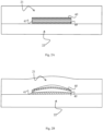
Figure 2A illustrates a sensor inserted in a seat provided in the rim of the wheel ofFigure 1 ; -
Figure 2B schematically illustrates a deformation of the rim and of the sensor ofFigure 2A when the wheel is subject to a vertical load; -
Figure 3 illustrates the attenuation of the output signal of the sensor used in the wheel ofFigure 1 as the frequency and the dielectric material used changes; -
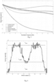
Figure 4 illustrates the output of the sensor ofFigure 1 as a function of the rotation angle of the wheel; -
Figure 5 illustrates the load variation measured by the sensor as a function of the rotation speed of the wheel; -
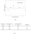
Figure 6 is a table that shows the influence of the longitudinal load on the measurement of the vertical one; -
Figure 7 illustrates the variation of the load measurement as the pressure increases; -
Figure 8 illustrates the measurement of the vertical load when a vertical and a horizontal load are applied; -
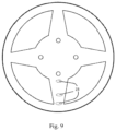
Figure 9 shows an alternative rim to that offigure 1 ; -
Figures 10A, 10B, 10C, 10D, 10E show different alternative embodiments for the plates of a capacitive sensor. - In the following description, for the illustration of the figures, identical numbers or reference symbols are used to indicate construction elements with the same function. Further, for illustration clarity, some references may not be repeated in all the figures.
- While the invention is susceptible to various modifications and alternative constructions, certain preferred embodiments are shown in the drawings and are described hereinbelow in detail. It is in any case to be noted that there is no intention to limit the invention to the specific embodiment illustrated, rather on the contrary, the invention intends covering all the modifications, alternative and equivalent constructions that fall within the scope of the invention as defined in the claims.
- The use of "for example", "etc.", "or" indicates non-exclusive alternatives without limitation, unless otherwise indicated. The use of "comprises" and "includes" means "comprises or includes, but not limited to", unless otherwise indicated.
- With reference to
Figure 1 a sectional view of awheel 1 is illustrated according to an embodiment of the present invention. In the following description the wheel is considered in the mounted condition, i.e. with a horizontal rotation axis. - The
wheel 1 comprises in a known way arim 2 on which atyre 3 is mounted, and a measuring system able to measure a vertical load applied to the wheel in mounted conditions with a horizontal rotation axis. - In the example of
Figure 1 the rim is of the type comprising afrontal disc 20 welded to anannular element 21 whose radial surface forms the so-calledchannel 22 intended to house theheel 30 of thetyre 3. - The
rim 1 is provided with a seat 23 in which a sensor 4 is housed that can detect deformations of the seat 23. Preferably the sensor 4 is a capacitive sensor, therefore provided with two conductingplates 40 separated by adielectric material 41. - The
dielectric material 41 can be of various types, however, preferred materials are cellulose acetate, copolymers, fluoropolymers, thermopolymers and Tedlar®. Experimental tests performed by the Applicant (seeFig. 3 ), have demonstrated that these materials have reduced signal attenuation (percentage less than 10%) for the frequencies of interest, comprised between 0 and 50 Hz, corresponding to the rotation frequency of the sensor mounted on a rim of 22" of a vehicle that travels at a speed comprised between 0 and 130 km/h. - As illustrated in
Figure 2A , in conditions of null load applied to the wheel, the twoelements fig.2B ), the twoelements plates 40 of the sensor 4 move translating and rotating with respect to each other. Such movement of the plates causes a deformation of thedielectric material 41 and, therefore, a variation of the electric signal generated by the sensor. The variation of the electric signal of the sensor therefore depends on the load applied to the wheel and its measurement can be used to measure the load on the wheel. - Advantageously, the plates of the capacitive sensor are shielded by means of a conductive layer, so as to reduce the noise coming from the vehicle, e.g. due to capacity due to contact between wheel and vehicle/ground.
- In the example of
Figure 1 , the capacitive sensor 4 is mounted on a PCB that also houses an analog-to-digital converter 5. The output of the sensor 4 is connected to the input of the analog-to-digital converter (A/D) 5, which converts the analog signal at the output of the sensor 4 into a digital signal that is then sent, throughappropriate wiring 10, to a storage andprocessing unit 6, which performs a first local processing of the measurement of the sensor 4 and supplies the data to awireless transmitter module 7 which transmits them to a remote unit, not illustrated in the figure, but preferably mounted on board the vehicle, e.g. a car or truck, on which thewheel 1 is mounted. - In the example of
Figure 1 , thewireless transmitter 7 and the storage andprocessing unit 6 are housed in acase 8 that also houses an electric battery 9 able to supply the transmitter and all the other active elements of the system, such as the sensor 4, the A/D converter 5. - Experimental tests, reported in
Figure 4 , have made it possible to verify that by applying a constant vertical load to the wheel, as the latter rotates, the output signal of the sensor has a peak LMAX, when the sensor is located along the horizontal (values of 90° and 270° in the graphs ofFigure 4 ). The output signal of the sensor, instead, has an absolute minimum value LMIN when it is in the lowest part of the wheel (values of 0 and 360° in the graph offigure 4 ), and a relative minimum Lt_med when it is in the highest point of the wheel (value of 180° in the graph ofFigure 4 ). - Preferably, the absolute maximum LMAX, absolute minimum LMIN and relative minimum Lt_med values are considered net of the disturbances and noise associated with the output signal of the sensor 4, as appears clear to a person skilled in the art from the example of
Figure 4 . For example, the absolute maximum and minimum and relative values can be detected after filtering - such as lowpass filtering or bandpass filtering - of the output signal of the sensor 4, performed by theprocessing unit 6. - The Applicant has therefore, empirically, discovered that the lateral FL and vertical Fv forces acting on the wheel can be obtained according to the following formula (1):

- In order to be able to calculate the vertical load Fv and lateral load FL values, in a preferred embodiment the system for measuring the loads applied to the wheel also comprises means adapted to detect a pressure and temperature value of the tyre mounted on the rim. In one embodiment the means adapted to detect a pressure and temperature value comprise a sensor, e.g. a TPMS sensor, able to measure the inflation pressure of the tyre and the temperature of the air inside the tyre, the latter being connected to the temperature of the tyre itself.
- In particular, it is to be noted that although the use of a pressure sensor is preferable for measuring the pressure of the tyre, other systems may be used, which indirectly determine a pressure value by measuring other parameters. For example, the measurement of the distance between the rim and the tyre depends on the shape, but also on the pressure, of the tyre, so that differential measurements of the distance between the rim and the tyre can be considered indirect measurements of the tyre pressure.
- The means for detecting a pressure and temperature value of the tyre mounted on the rim can be mounted on the wheel, or be means already provided on the vehicle that mounts the wheel. In this case the storage and
processing unit 6 can receive the pressure and temperature data from the remote unit of the vehicle through thewireless interface 7 that operates both as a transmitting module, as previously described, and as a receiving module for receiving data and/or controls from the remote unit of the vehicle. - In general, the coefficient values Cij can be empirically measured. The Applicant has verified that in tyre pressure conditions of 4 bar and temperature of 20°C the following values are recorded:


- In general, in usual operating conditions of a wheel, i.e. T comprised between - 15°C and T=45°C, and tyre pressure p comprised between 3 and 4.5 bar (commercial vehicle), the values mentioned above can vary by ± 10%.
- Although slightly less accurate, given that the temperature drift is not very important in formula (1), in an embodiment that does not require any temperature sensor, the values K1 and K2 can be assumed to be equal to zero in formula (1). Through experimental tests, the Applicant has also verified the existence of a linear relationship between the pressure of the tyre P and the coefficients Cij. The graph of
Figure 7 shows how, with the same vertical load applied, as the pressure increases the load value measured by the sensor also increases. - Therefore, the
processing unit 6 is preferably configured to correct the value of coefficients Cij of formula (1) as follows:
processing unit 6. In one embodiment, the storage andprocessing unit 6 can comprise different values of k stored in a comparison table where, for different types of tyre and tyre pressure, a predetermined value of k is associated. At the time of mounting the wheel on the vehicle, the mechanic can interface with the storage and processing unit through an appropriate user interface (e.g. a remote control terminal that communicates in Bluetooth to the unit 6) for selecting the value of k. - Experimental tests, reported in
Figure 8 , have further demonstrated the effect of lateral forces on the measurement of the vertical force by the sensor that determine the ratio between the coefficients Cij. - Operatively, therefore, as the
wheel 1 turns, the plates of the capacitive sensor 4 move with respect to each other deforming the dielectrics interposed between them. This implies a variation to the signal generated by the sensor which, under ideal conditions, is repeated cyclically at each rotation and that has an absolute maximum LMAX, an absolute minimum LMIN and a relative minimum Lt_med. Theprocessing unit 6 detects and stores these three values and calculates the values the values of the horizontal forces FL and vertical forces FV acting on the wheel. - The
processing unit 6 transmits at least the value of the vertical force FV, but preferably also the value of the horizontal force FO to thewireless transmitter 7. - The signal transmitted by the
transmitter 7 is received by a remote control unit that re-transmits the signal (possibly re-processed) to external devices (e.g. remote control units) and/or uses the information transported by such signal (i.e. FL and FV) for controlling actuators of the vehicle, e.g. for switching on alarm signals in the case of sudden variations of the load measured by a wheel. - Experimental tests have made it possible to verify that the system described above is resistant to noise and other factors that can in some way affect the measurement.
- In particular, as illustrated in
Figure 5 , the influence of the vehicle's translation speed is less than 4% and is random. - Experimental tests have then made it possible to verify (see table in
Figure 6 ) that the influence of the longitudinal load on the measurement of the vertical one is less than 3%. - Furthermore, as will be clear to a person skilled in the art, the system according to the embodiments of the present invention requires a single deformation signal for precisely identifying the horizontal forces FL and vertical forces FV acting on the wheel. This allows a system to be realized with extremely reduced dimensions and a single cable - for connecting the single sensor 4 to the storage and
processing unit 6. - In light of what is described above it is clear to a person skilled in the art how the invention allows the intended objects to be reached. In particular, the positioning of the sensor in a seat obtained in the rim of the wheel allows easy installation and facilitated access to the sensor in case of maintenance.
- Advantageously, the seat for the sensor is positioned in a point of the rim that is subject to the vertical load acting on the wheel, e.g. a portion of the channel for housing the tyre, or a spoke of a spoked rim.
Figure 9 , for example, indicates different possible positions of a seat 23 for the sensor. Preferably, in case of spoked rims, a preferred position for the seat 23 is an area of the spoke that is located in the most external half of the spoke itself, i.e. in the proximal position of the channel. - For example, despite the invention being described above with reference to a capacitive type sensor, it is clear that the sensor can also be of another type, e.g. optical or inductive sensors can be provided, which measure deformations of a seat obtained in the rim.
- Again, in the preferred solution of a capacitive condenser, it is clear that the sensor can have parallel plane plates or also of another type. For example, the plates can comprise parallel flat plane surfaces (e.g.
Figures 10A and 10B ) of any shape (e.g. rectangular as inFig. 10A or elliptical as inFig. 10B ), or comprise curved plane surfaces (fig. 10C ), comprise semi-circular surfaces (Fig. 10E ), have a constant thickness along the whole width thereof (e.g.Fig. 10A-10C ) have a thickness 'D' that varies along the width, e.g. being maximum at the centre and minimum at the edges as inFig. 10D .
Claims (13)
- Rim (2) for wheel (1) including a measuring system (4, 5, 6) to detect a vertical load (Fv) applied to the wheel (1) in operating conditions with wheel mounted with horizontal rotation axis, the measuring system comprising:- a sensor (4) to detect a deformation of the rim and to transmit a deformation signal related to the detected deformation, and- a processing unit (6), operatively connected to the sensor (4), configured to receive the deformation signal, and to determine the vertical load applied to the wheel (1), based on the deformation of the rim detected by the sensor (4), characterized in thatthe processing unit:detects and stores a first value (LMIN) of absolute minimum, a second value (LMAX) of absolute maximum and a value (Lt_med) of relative minimum of the deformation signal generated by said sensor (4) during a rotation of the rim (2), andcalculates the value of the vertical (FV) load acting on the wheel, based on the first value (LMIN) of absolute minimum, the second value (LMAX) of absolute maximum and the value (Lt_med) of relative minimum of the deformation signal generated by said sensor (4) stored.
- Rim according to claim 1, wherein the sensor (4) is housed in a seat (23) on a surface of the rim, said seat comprising two walls (21, 22) facing each other, and wherein the sensor is adapted to detect a deformation of said seat (23), said deformation of the seat (23) being caused by a deformation of the two walls due to a load applied to wheel (1) coupled with the rim (2).
- Rim according to claim 2, further comprising a plurality of spokes and wherein the seat (23) is obtained on a spoke of the said plurality of spokes.
- Rim according to claim 2, further including an annular element to house a tyre, and a frontal disc applied to the annular element, and wherein the seat (23) is obtained on an area of the said disc that faces said annular element.
- Rim according to claim 2 or 3 or 4, wherein the sensor (4) is a capacitive type sensor comprising a pair of conducting plates (40) and a dielectric material (41) interposed between said conducting plates.
- Rim according to claim 5, wherein a first conducting plate (40) of the pair of conducting plates (40) is adjacent to a first wall (21) of the two walls (21, 22) of the seat (23) and a second conducting plate (40) is adjacent to a second wall (22) of the two walls (21,22) of the seat (23), the conducting plates (40) translating and rotating with respect to each other by a deformation of the two walls due to a load applied to wheel (1) coupled with the rim (2) causing a deformation of the dielectric material (41).
- Rim According to claim 5 or 6, wherein this dielectric material is chosen in the group of materials comprising the following materials: cellulose acetate, copolymers, fluoropolymers, Polymers, Tedlar®.
- Rim according to any of the previous claims, wherein the processing unit is further adapted to calculate a value of the vertical load applied to the wheel according to the following formula:

- Rim according to any of claims 1 to 8, further comprising means adapted to detect a temperature value of the tyre and wherein said processing unit (6) is adapted to store measurements made by said sensor (4), and wherein the processing unit is further adapted to calculate a value of the vertical load applied to the wheel according to the following formula:

- Rim according to claim 8 or 9, further comprising means for detecting pressure of a tyre mounted on said rim, and where the processing unit (6) is configured to correct the value of the Cij coefficients as follows:

- Wheel comprising a rim according to any of the claims from 1 to 10 and a tyre mounted on that rim.
- Vehicle comprising a wheel according to claim 11, wherein the measurement system comprises a wireless transmitter module (7) to transmit measurements of the load acting on the wheel, and wherein the vehicle comprises a remote unit adapted to receive said measurements of the load acting on the wheel.
- Vehicle according to claim 12, further comprising a plurality of actuators, wherein the remote unit uses the measurements of the load acting on the wheel to control at least one actuator of said plurality of actuators.
Applications Claiming Priority (2)
| Application Number | Priority Date | Filing Date | Title |
|---|---|---|---|
| IT102018000003697A IT201800003697A1 (en) | 2018-03-16 | 2018-03-16 | RIM WITH SENSOR AND WHEEL INCLUDING THIS RIM |
| PCT/IB2019/052091 WO2019175833A1 (en) | 2018-03-16 | 2019-03-14 | Rim for wheel with sensor and wheel comprising said rim |
Publications (2)
| Publication Number | Publication Date |
|---|---|
| EP3765828A1 EP3765828A1 (en) | 2021-01-20 |
| EP3765828B1 true EP3765828B1 (en) | 2023-04-26 |
Family
ID=62530440
Family Applications (1)
| Application Number | Title | Priority Date | Filing Date |
|---|---|---|---|
| EP19714483.5A Active EP3765828B1 (en) | 2018-03-16 | 2019-03-14 | Rim with sensor and wheel including that rim |
Country Status (4)
| Country | Link |
|---|---|
| US (1) | US11701928B2 (en) |
| EP (1) | EP3765828B1 (en) |
| IT (1) | IT201800003697A1 (en) |
| WO (1) | WO2019175833A1 (en) |
Families Citing this family (3)
| Publication number | Priority date | Publication date | Assignee | Title |
|---|---|---|---|---|
| DE202021103142U1 (en) | 2021-06-10 | 2022-11-09 | Maxion Wheels Holding Gmbh | Vehicle wheel with measuring device and monitoring device for vehicles |
| CN117141163A (en) * | 2023-09-11 | 2023-12-01 | 上海为彪汽配制造有限公司 | Vehicle tire monitoring device, method and vehicle |
| CN118294056B (en) * | 2024-04-07 | 2024-10-15 | 中国农业大学 | A pin-type tire force measuring system and testing method |
Family Cites Families (12)
| Publication number | Priority date | Publication date | Assignee | Title |
|---|---|---|---|---|
| SE501814C2 (en) | 1993-08-06 | 1995-05-22 | Skf Ab | Device for load measurement in rolling bearings |
| DE19613916C2 (en) | 1996-04-06 | 2001-12-06 | Daimler Chrysler Ag | Method and device for tire monitoring in a vehicle |
| DE19744611A1 (en) | 1997-10-09 | 1999-04-15 | Valentin Dr Ing Magori | Sensor for detecting tire condition in motor vehicle |
| DE10001272C2 (en) * | 2000-01-14 | 2003-08-21 | Markus Fach | Device and method for determining forces in the tire of a vehicle wheel |
| AU2003235461A1 (en) | 2002-06-21 | 2004-01-06 | Bridgestone Corporation | Tire acting force measuring method, and tire acting force measuring device |
| JP2004233331A (en) * | 2002-12-04 | 2004-08-19 | Sumitomo Rubber Ind Ltd | Wheel force detecting device and wheel force detecting method |
| AU2003304318A1 (en) * | 2003-07-04 | 2005-01-28 | Pirelli Pneumatici S.P.A. | Method and system for determining a tyre load during the running of a motor vehicle |
| DE112004001197T5 (en) | 2003-07-04 | 2006-06-08 | Ntn Corp. | Wheel carrier-bearing arrangement with built-in load sensor |
| EP1747439B1 (en) * | 2004-05-12 | 2012-03-21 | PIRELLI TYRE S.p.A. | Method for determining a force at the hub of a wheel of a vehicle whilst traveling and wheel suitable for allowing said method to be carried out |
| US20090180722A1 (en) | 2006-03-06 | 2009-07-16 | The Timken Company | Load sensing wheel end |
| ES2363400B2 (en) * | 2011-03-03 | 2011-12-20 | Universidad Politécnica de Madrid | METHOD AND ESTIMATION SYSTEM OF EFFORTS GENERATED BY THE TIRE CONTACT WITH THE SHOE IN AN INSTRUMENTALIZED RIM. |
| WO2018016236A1 (en) * | 2016-07-19 | 2018-01-25 | 日本精工株式会社 | Wheel equipped with sensing device |
-
2018
- 2018-03-16 IT IT102018000003697A patent/IT201800003697A1/en unknown
-
2019
- 2019-03-14 US US16/981,401 patent/US11701928B2/en active Active
- 2019-03-14 WO PCT/IB2019/052091 patent/WO2019175833A1/en not_active Ceased
- 2019-03-14 EP EP19714483.5A patent/EP3765828B1/en active Active
Also Published As
| Publication number | Publication date |
|---|---|
| EP3765828A1 (en) | 2021-01-20 |
| US11701928B2 (en) | 2023-07-18 |
| WO2019175833A1 (en) | 2019-09-19 |
| US20210023893A1 (en) | 2021-01-28 |
| IT201800003697A1 (en) | 2019-09-16 |
Similar Documents
| Publication | Publication Date | Title |
|---|---|---|
| US7673505B2 (en) | Tire footprint determination apparatuses, systems and methods | |
| US8584517B2 (en) | Load based wheel position determination | |
| US20240351381A1 (en) | Method and system for monitoring a parameter related to a tire during the running of a vehicle | |
| EP1487682B1 (en) | Method and system for monitoring a tyre during the running of a vehicle | |
| EP1675735B1 (en) | Method and system for determining a tyre load during the running of a vehicle | |
| EP1263616B1 (en) | System, tyre and method for determining the behaviour of a tyre in motion | |
| US8096174B2 (en) | Vehicle load weight detecting apparatus | |
| EP3765828B1 (en) | Rim with sensor and wheel including that rim | |
| US9061662B2 (en) | Method and device for continuously determining wheel state variables of a wheel | |
| JP2017149414A (en) | Tire sensor | |
| JP7072063B2 (en) | A method and system for signaling the aquaplane status of tires mounted on a vehicle | |
| JP2014227124A (en) | Wheel position determination device | |
| JP3993899B2 (en) | Safety insert that generates a transverse vibration signal and device for detecting tire support on the safety insert | |
| JPH10297228A (en) | Tire pneumatic pressure alarm device | |
| CN106794729A (en) | For the methods, devices and systems of the automatic detection of wheel rim parameter | |
| JP6425883B2 (en) | Tire pressure drop detection device for automobile tires | |
| Gobbi et al. | Rim for wheel with sensor and wheel comprising said rim | |
| KR20210067011A (en) | Road condition diagnosis system and wheel bearing provided therewith | |
| CN120380311A (en) | Wheel load determining apparatus and method | |
| WO2025141451A1 (en) | Method and sistem for detecting an aquaplane condition of a tyre mounted on a vehicle | |
| WO2025141450A1 (en) | Method for equipping a tyre with a device for monitoring at least one parameter characteristics of an interaction between the tyre and a tyre rolling surface, and tyre equipped with a monitoring device | |
| KR101744714B1 (en) | Method and apparatus for detecting tire deflation |
Legal Events
| Date | Code | Title | Description |
|---|---|---|---|
| STAA | Information on the status of an ep patent application or granted ep patent |
Free format text: STATUS: UNKNOWN |
|
| STAA | Information on the status of an ep patent application or granted ep patent |
Free format text: STATUS: THE INTERNATIONAL PUBLICATION HAS BEEN MADE |
|
| PUAI | Public reference made under article 153(3) epc to a published international application that has entered the european phase |
Free format text: ORIGINAL CODE: 0009012 |
|
| STAA | Information on the status of an ep patent application or granted ep patent |
Free format text: STATUS: REQUEST FOR EXAMINATION WAS MADE |
|
| 17P | Request for examination filed |
Effective date: 20201002 |
|
| AK | Designated contracting states |
Kind code of ref document: A1 Designated state(s): AL AT BE BG CH CY CZ DE DK EE ES FI FR GB GR HR HU IE IS IT LI LT LU LV MC MK MT NL NO PL PT RO RS SE SI SK SM TR |
|
| AX | Request for extension of the european patent |
Extension state: BA ME |
|
| DAV | Request for validation of the european patent (deleted) | ||
| DAX | Request for extension of the european patent (deleted) | ||
| RIN1 | Information on inventor provided before grant (corrected) |
Inventor name: GOBBI, MASSIMILIANO Inventor name: MASTINU, GIANPIERO Inventor name: DELL'AGOSTINO, STEFANO |
|
| GRAP | Despatch of communication of intention to grant a patent |
Free format text: ORIGINAL CODE: EPIDOSNIGR1 |
|
| STAA | Information on the status of an ep patent application or granted ep patent |
Free format text: STATUS: GRANT OF PATENT IS INTENDED |
|
| INTG | Intention to grant announced |
Effective date: 20230201 |
|
| GRAS | Grant fee paid |
Free format text: ORIGINAL CODE: EPIDOSNIGR3 |
|
| GRAA | (expected) grant |
Free format text: ORIGINAL CODE: 0009210 |
|
| STAA | Information on the status of an ep patent application or granted ep patent |
Free format text: STATUS: THE PATENT HAS BEEN GRANTED |
|
| AK | Designated contracting states |
Kind code of ref document: B1 Designated state(s): AL AT BE BG CH CY CZ DE DK EE ES FI FR GB GR HR HU IE IS IT LI LT LU LV MC MK MT NL NO PL PT RO RS SE SI SK SM TR |
|
| REG | Reference to a national code |
Ref country code: GB Ref legal event code: FG4D |
|
| REG | Reference to a national code |
Ref country code: CH Ref legal event code: EP |
|
| REG | Reference to a national code |
Ref country code: DE Ref legal event code: R096 Ref document number: 602019028034 Country of ref document: DE |
|
| REG | Reference to a national code |
Ref country code: AT Ref legal event code: REF Ref document number: 1563143 Country of ref document: AT Kind code of ref document: T Effective date: 20230515 |
|
| REG | Reference to a national code |
Ref country code: IE Ref legal event code: FG4D |
|
| P01 | Opt-out of the competence of the unified patent court (upc) registered |
Effective date: 20230615 |
|
| REG | Reference to a national code |
Ref country code: LT Ref legal event code: MG9D |
|
| REG | Reference to a national code |
Ref country code: NL Ref legal event code: MP Effective date: 20230426 |
|
| REG | Reference to a national code |
Ref country code: AT Ref legal event code: MK05 Ref document number: 1563143 Country of ref document: AT Kind code of ref document: T Effective date: 20230426 |
|
| PG25 | Lapsed in a contracting state [announced via postgrant information from national office to epo] |
Ref country code: NL Free format text: LAPSE BECAUSE OF FAILURE TO SUBMIT A TRANSLATION OF THE DESCRIPTION OR TO PAY THE FEE WITHIN THE PRESCRIBED TIME-LIMIT Effective date: 20230426 |
|
| PG25 | Lapsed in a contracting state [announced via postgrant information from national office to epo] |
Ref country code: SE Free format text: LAPSE BECAUSE OF FAILURE TO SUBMIT A TRANSLATION OF THE DESCRIPTION OR TO PAY THE FEE WITHIN THE PRESCRIBED TIME-LIMIT Effective date: 20230426 Ref country code: PT Free format text: LAPSE BECAUSE OF FAILURE TO SUBMIT A TRANSLATION OF THE DESCRIPTION OR TO PAY THE FEE WITHIN THE PRESCRIBED TIME-LIMIT Effective date: 20230828 Ref country code: NO Free format text: LAPSE BECAUSE OF FAILURE TO SUBMIT A TRANSLATION OF THE DESCRIPTION OR TO PAY THE FEE WITHIN THE PRESCRIBED TIME-LIMIT Effective date: 20230726 Ref country code: ES Free format text: LAPSE BECAUSE OF FAILURE TO SUBMIT A TRANSLATION OF THE DESCRIPTION OR TO PAY THE FEE WITHIN THE PRESCRIBED TIME-LIMIT Effective date: 20230426 Ref country code: AT Free format text: LAPSE BECAUSE OF FAILURE TO SUBMIT A TRANSLATION OF THE DESCRIPTION OR TO PAY THE FEE WITHIN THE PRESCRIBED TIME-LIMIT Effective date: 20230426 |
|
| PG25 | Lapsed in a contracting state [announced via postgrant information from national office to epo] |
Ref country code: RS Free format text: LAPSE BECAUSE OF FAILURE TO SUBMIT A TRANSLATION OF THE DESCRIPTION OR TO PAY THE FEE WITHIN THE PRESCRIBED TIME-LIMIT Effective date: 20230426 Ref country code: PL Free format text: LAPSE BECAUSE OF FAILURE TO SUBMIT A TRANSLATION OF THE DESCRIPTION OR TO PAY THE FEE WITHIN THE PRESCRIBED TIME-LIMIT Effective date: 20230426 Ref country code: LV Free format text: LAPSE BECAUSE OF FAILURE TO SUBMIT A TRANSLATION OF THE DESCRIPTION OR TO PAY THE FEE WITHIN THE PRESCRIBED TIME-LIMIT Effective date: 20230426 Ref country code: LT Free format text: LAPSE BECAUSE OF FAILURE TO SUBMIT A TRANSLATION OF THE DESCRIPTION OR TO PAY THE FEE WITHIN THE PRESCRIBED TIME-LIMIT Effective date: 20230426 Ref country code: IS Free format text: LAPSE BECAUSE OF FAILURE TO SUBMIT A TRANSLATION OF THE DESCRIPTION OR TO PAY THE FEE WITHIN THE PRESCRIBED TIME-LIMIT Effective date: 20230826 Ref country code: HR Free format text: LAPSE BECAUSE OF FAILURE TO SUBMIT A TRANSLATION OF THE DESCRIPTION OR TO PAY THE FEE WITHIN THE PRESCRIBED TIME-LIMIT Effective date: 20230426 Ref country code: GR Free format text: LAPSE BECAUSE OF FAILURE TO SUBMIT A TRANSLATION OF THE DESCRIPTION OR TO PAY THE FEE WITHIN THE PRESCRIBED TIME-LIMIT Effective date: 20230727 |
|
| PG25 | Lapsed in a contracting state [announced via postgrant information from national office to epo] |
Ref country code: FI Free format text: LAPSE BECAUSE OF FAILURE TO SUBMIT A TRANSLATION OF THE DESCRIPTION OR TO PAY THE FEE WITHIN THE PRESCRIBED TIME-LIMIT Effective date: 20230426 |
|
| PG25 | Lapsed in a contracting state [announced via postgrant information from national office to epo] |
Ref country code: SK Free format text: LAPSE BECAUSE OF FAILURE TO SUBMIT A TRANSLATION OF THE DESCRIPTION OR TO PAY THE FEE WITHIN THE PRESCRIBED TIME-LIMIT Effective date: 20230426 |
|
| REG | Reference to a national code |
Ref country code: DE Ref legal event code: R097 Ref document number: 602019028034 Country of ref document: DE |
|
| PG25 | Lapsed in a contracting state [announced via postgrant information from national office to epo] |
Ref country code: SM Free format text: LAPSE BECAUSE OF FAILURE TO SUBMIT A TRANSLATION OF THE DESCRIPTION OR TO PAY THE FEE WITHIN THE PRESCRIBED TIME-LIMIT Effective date: 20230426 Ref country code: SK Free format text: LAPSE BECAUSE OF FAILURE TO SUBMIT A TRANSLATION OF THE DESCRIPTION OR TO PAY THE FEE WITHIN THE PRESCRIBED TIME-LIMIT Effective date: 20230426 Ref country code: RO Free format text: LAPSE BECAUSE OF FAILURE TO SUBMIT A TRANSLATION OF THE DESCRIPTION OR TO PAY THE FEE WITHIN THE PRESCRIBED TIME-LIMIT Effective date: 20230426 Ref country code: EE Free format text: LAPSE BECAUSE OF FAILURE TO SUBMIT A TRANSLATION OF THE DESCRIPTION OR TO PAY THE FEE WITHIN THE PRESCRIBED TIME-LIMIT Effective date: 20230426 Ref country code: DK Free format text: LAPSE BECAUSE OF FAILURE TO SUBMIT A TRANSLATION OF THE DESCRIPTION OR TO PAY THE FEE WITHIN THE PRESCRIBED TIME-LIMIT Effective date: 20230426 Ref country code: CZ Free format text: LAPSE BECAUSE OF FAILURE TO SUBMIT A TRANSLATION OF THE DESCRIPTION OR TO PAY THE FEE WITHIN THE PRESCRIBED TIME-LIMIT Effective date: 20230426 |
|
| PLBE | No opposition filed within time limit |
Free format text: ORIGINAL CODE: 0009261 |
|
| STAA | Information on the status of an ep patent application or granted ep patent |
Free format text: STATUS: NO OPPOSITION FILED WITHIN TIME LIMIT |
|
| 26N | No opposition filed |
Effective date: 20240129 |
|
| PG25 | Lapsed in a contracting state [announced via postgrant information from national office to epo] |
Ref country code: SI Free format text: LAPSE BECAUSE OF FAILURE TO SUBMIT A TRANSLATION OF THE DESCRIPTION OR TO PAY THE FEE WITHIN THE PRESCRIBED TIME-LIMIT Effective date: 20230426 |
|
| PG25 | Lapsed in a contracting state [announced via postgrant information from national office to epo] |
Ref country code: SI Free format text: LAPSE BECAUSE OF FAILURE TO SUBMIT A TRANSLATION OF THE DESCRIPTION OR TO PAY THE FEE WITHIN THE PRESCRIBED TIME-LIMIT Effective date: 20230426 |
|
| PGFP | Annual fee paid to national office [announced via postgrant information from national office to epo] |
Ref country code: IT Payment date: 20240327 Year of fee payment: 6 |
|
| PGFP | Annual fee paid to national office [announced via postgrant information from national office to epo] |
Ref country code: DE Payment date: 20240403 Year of fee payment: 6 |
|
| REG | Reference to a national code |
Ref country code: CH Ref legal event code: PL |
|
| PG25 | Lapsed in a contracting state [announced via postgrant information from national office to epo] |
Ref country code: BG Free format text: LAPSE BECAUSE OF FAILURE TO SUBMIT A TRANSLATION OF THE DESCRIPTION OR TO PAY THE FEE WITHIN THE PRESCRIBED TIME-LIMIT Effective date: 20230426 |
|
| PG25 | Lapsed in a contracting state [announced via postgrant information from national office to epo] |
Ref country code: LU Free format text: LAPSE BECAUSE OF NON-PAYMENT OF DUE FEES Effective date: 20240314 |
|
| PG25 | Lapsed in a contracting state [announced via postgrant information from national office to epo] |
Ref country code: MC Free format text: LAPSE BECAUSE OF FAILURE TO SUBMIT A TRANSLATION OF THE DESCRIPTION OR TO PAY THE FEE WITHIN THE PRESCRIBED TIME-LIMIT Effective date: 20230426 |
|
| GBPC | Gb: european patent ceased through non-payment of renewal fee |
Effective date: 20240314 |
|
| PG25 | Lapsed in a contracting state [announced via postgrant information from national office to epo] |
Ref country code: MC Free format text: LAPSE BECAUSE OF FAILURE TO SUBMIT A TRANSLATION OF THE DESCRIPTION OR TO PAY THE FEE WITHIN THE PRESCRIBED TIME-LIMIT Effective date: 20230426 Ref country code: LU Free format text: LAPSE BECAUSE OF NON-PAYMENT OF DUE FEES Effective date: 20240314 Ref country code: BG Free format text: LAPSE BECAUSE OF FAILURE TO SUBMIT A TRANSLATION OF THE DESCRIPTION OR TO PAY THE FEE WITHIN THE PRESCRIBED TIME-LIMIT Effective date: 20230426 |
|
| REG | Reference to a national code |
Ref country code: BE Ref legal event code: MM Effective date: 20240331 |
|
| PG25 | Lapsed in a contracting state [announced via postgrant information from national office to epo] |
Ref country code: BE Free format text: LAPSE BECAUSE OF NON-PAYMENT OF DUE FEES Effective date: 20240331 |
|
| PG25 | Lapsed in a contracting state [announced via postgrant information from national office to epo] |
Ref country code: GB Free format text: LAPSE BECAUSE OF NON-PAYMENT OF DUE FEES Effective date: 20240314 |
|
| PG25 | Lapsed in a contracting state [announced via postgrant information from national office to epo] |
Ref country code: FR Free format text: LAPSE BECAUSE OF NON-PAYMENT OF DUE FEES Effective date: 20240331 |
|
| PG25 | Lapsed in a contracting state [announced via postgrant information from national office to epo] |
Ref country code: IE Free format text: LAPSE BECAUSE OF NON-PAYMENT OF DUE FEES Effective date: 20240314 |
|
| PG25 | Lapsed in a contracting state [announced via postgrant information from national office to epo] |
Ref country code: IE Free format text: LAPSE BECAUSE OF NON-PAYMENT OF DUE FEES Effective date: 20240314 Ref country code: GB Free format text: LAPSE BECAUSE OF NON-PAYMENT OF DUE FEES Effective date: 20240314 Ref country code: FR Free format text: LAPSE BECAUSE OF NON-PAYMENT OF DUE FEES Effective date: 20240331 Ref country code: BE Free format text: LAPSE BECAUSE OF NON-PAYMENT OF DUE FEES Effective date: 20240331 Ref country code: CH Free format text: LAPSE BECAUSE OF NON-PAYMENT OF DUE FEES Effective date: 20240331 |
|
| PG25 | Lapsed in a contracting state [announced via postgrant information from national office to epo] |
Ref country code: CY Free format text: LAPSE BECAUSE OF FAILURE TO SUBMIT A TRANSLATION OF THE DESCRIPTION OR TO PAY THE FEE WITHIN THE PRESCRIBED TIME-LIMIT; INVALID AB INITIO Effective date: 20190314 |
|
| PG25 | Lapsed in a contracting state [announced via postgrant information from national office to epo] |
Ref country code: HU Free format text: LAPSE BECAUSE OF FAILURE TO SUBMIT A TRANSLATION OF THE DESCRIPTION OR TO PAY THE FEE WITHIN THE PRESCRIBED TIME-LIMIT; INVALID AB INITIO Effective date: 20190314 |
|
| REG | Reference to a national code |
Ref country code: DE Ref legal event code: R119 Ref document number: 602019028034 Country of ref document: DE |
|
| PG25 | Lapsed in a contracting state [announced via postgrant information from national office to epo] |
Ref country code: TR Free format text: LAPSE BECAUSE OF FAILURE TO SUBMIT A TRANSLATION OF THE DESCRIPTION OR TO PAY THE FEE WITHIN THE PRESCRIBED TIME-LIMIT Effective date: 20230426 |
|
| PG25 | Lapsed in a contracting state [announced via postgrant information from national office to epo] |
Ref country code: DE Free format text: LAPSE BECAUSE OF NON-PAYMENT OF DUE FEES Effective date: 20251001 |
|
| PG25 | Lapsed in a contracting state [announced via postgrant information from national office to epo] |
Ref country code: IT Free format text: LAPSE BECAUSE OF NON-PAYMENT OF DUE FEES Effective date: 20250314 |