EP3765742B1 - Method and apparatus related to servicing of liquid ring pumps - Google Patents
Method and apparatus related to servicing of liquid ring pumps Download PDFInfo
- Publication number
- EP3765742B1 EP3765742B1 EP19767637.2A EP19767637A EP3765742B1 EP 3765742 B1 EP3765742 B1 EP 3765742B1 EP 19767637 A EP19767637 A EP 19767637A EP 3765742 B1 EP3765742 B1 EP 3765742B1
- Authority
- EP
- European Patent Office
- Prior art keywords
- shaft
- housing
- liquid ring
- ring pump
- component
- Prior art date
- Legal status (The legal status is an assumption and is not a legal conclusion. Google has not performed a legal analysis and makes no representation as to the accuracy of the status listed.)
- Active
Links
Images

Classifications
-
- F—MECHANICAL ENGINEERING; LIGHTING; HEATING; WEAPONS; BLASTING
- F04—POSITIVE - DISPLACEMENT MACHINES FOR LIQUIDS; PUMPS FOR LIQUIDS OR ELASTIC FLUIDS
- F04C—ROTARY-PISTON, OR OSCILLATING-PISTON, POSITIVE-DISPLACEMENT MACHINES FOR LIQUIDS; ROTARY-PISTON, OR OSCILLATING-PISTON, POSITIVE-DISPLACEMENT PUMPS
- F04C19/00—Rotary-piston pumps with fluid ring or the like, specially adapted for elastic fluids
-
- F—MECHANICAL ENGINEERING; LIGHTING; HEATING; WEAPONS; BLASTING
- F04—POSITIVE - DISPLACEMENT MACHINES FOR LIQUIDS; PUMPS FOR LIQUIDS OR ELASTIC FLUIDS
- F04C—ROTARY-PISTON, OR OSCILLATING-PISTON, POSITIVE-DISPLACEMENT MACHINES FOR LIQUIDS; ROTARY-PISTON, OR OSCILLATING-PISTON, POSITIVE-DISPLACEMENT PUMPS
- F04C7/00—Rotary-piston machines or pumps with fluid ring or the like
-
- F—MECHANICAL ENGINEERING; LIGHTING; HEATING; WEAPONS; BLASTING
- F04—POSITIVE - DISPLACEMENT MACHINES FOR LIQUIDS; PUMPS FOR LIQUIDS OR ELASTIC FLUIDS
- F04C—ROTARY-PISTON, OR OSCILLATING-PISTON, POSITIVE-DISPLACEMENT MACHINES FOR LIQUIDS; ROTARY-PISTON, OR OSCILLATING-PISTON, POSITIVE-DISPLACEMENT PUMPS
- F04C29/00—Component parts, details or accessories of pumps or pumping installations, not provided for in groups F04C18/00 - F04C28/00
- F04C29/0042—Driving elements, brakes, couplings, transmissions specially adapted for pumps
- F04C29/005—Means for transmitting movement from the prime mover to driven parts of the pump, e.g. clutches, couplings, transmissions
-
- F—MECHANICAL ENGINEERING; LIGHTING; HEATING; WEAPONS; BLASTING
- F04—POSITIVE - DISPLACEMENT MACHINES FOR LIQUIDS; PUMPS FOR LIQUIDS OR ELASTIC FLUIDS
- F04C—ROTARY-PISTON, OR OSCILLATING-PISTON, POSITIVE-DISPLACEMENT MACHINES FOR LIQUIDS; ROTARY-PISTON, OR OSCILLATING-PISTON, POSITIVE-DISPLACEMENT PUMPS
- F04C29/00—Component parts, details or accessories of pumps or pumping installations, not provided for in groups F04C18/00 - F04C28/00
- F04C29/12—Arrangements for admission or discharge of the working fluid, e.g. constructional features of the inlet or outlet
-
- F—MECHANICAL ENGINEERING; LIGHTING; HEATING; WEAPONS; BLASTING
- F04—POSITIVE - DISPLACEMENT MACHINES FOR LIQUIDS; PUMPS FOR LIQUIDS OR ELASTIC FLUIDS
- F04C—ROTARY-PISTON, OR OSCILLATING-PISTON, POSITIVE-DISPLACEMENT MACHINES FOR LIQUIDS; ROTARY-PISTON, OR OSCILLATING-PISTON, POSITIVE-DISPLACEMENT PUMPS
- F04C2230/00—Manufacture
- F04C2230/60—Assembly methods
-
- F—MECHANICAL ENGINEERING; LIGHTING; HEATING; WEAPONS; BLASTING
- F04—POSITIVE - DISPLACEMENT MACHINES FOR LIQUIDS; PUMPS FOR LIQUIDS OR ELASTIC FLUIDS
- F04C—ROTARY-PISTON, OR OSCILLATING-PISTON, POSITIVE-DISPLACEMENT MACHINES FOR LIQUIDS; ROTARY-PISTON, OR OSCILLATING-PISTON, POSITIVE-DISPLACEMENT PUMPS
- F04C2230/00—Manufacture
- F04C2230/60—Assembly methods
- F04C2230/604—Mounting devices for pumps or compressors
-
- F—MECHANICAL ENGINEERING; LIGHTING; HEATING; WEAPONS; BLASTING
- F04—POSITIVE - DISPLACEMENT MACHINES FOR LIQUIDS; PUMPS FOR LIQUIDS OR ELASTIC FLUIDS
- F04C—ROTARY-PISTON, OR OSCILLATING-PISTON, POSITIVE-DISPLACEMENT MACHINES FOR LIQUIDS; ROTARY-PISTON, OR OSCILLATING-PISTON, POSITIVE-DISPLACEMENT PUMPS
- F04C2230/00—Manufacture
- F04C2230/70—Disassembly methods
-
- F—MECHANICAL ENGINEERING; LIGHTING; HEATING; WEAPONS; BLASTING
- F04—POSITIVE - DISPLACEMENT MACHINES FOR LIQUIDS; PUMPS FOR LIQUIDS OR ELASTIC FLUIDS
- F04C—ROTARY-PISTON, OR OSCILLATING-PISTON, POSITIVE-DISPLACEMENT MACHINES FOR LIQUIDS; ROTARY-PISTON, OR OSCILLATING-PISTON, POSITIVE-DISPLACEMENT PUMPS
- F04C2230/00—Manufacture
- F04C2230/80—Repairing methods
-
- F—MECHANICAL ENGINEERING; LIGHTING; HEATING; WEAPONS; BLASTING
- F04—POSITIVE - DISPLACEMENT MACHINES FOR LIQUIDS; PUMPS FOR LIQUIDS OR ELASTIC FLUIDS
- F04C—ROTARY-PISTON, OR OSCILLATING-PISTON, POSITIVE-DISPLACEMENT MACHINES FOR LIQUIDS; ROTARY-PISTON, OR OSCILLATING-PISTON, POSITIVE-DISPLACEMENT PUMPS
- F04C2230/00—Manufacture
- F04C2230/85—Methods for improvement by repair or exchange of parts
-
- F—MECHANICAL ENGINEERING; LIGHTING; HEATING; WEAPONS; BLASTING
- F04—POSITIVE - DISPLACEMENT MACHINES FOR LIQUIDS; PUMPS FOR LIQUIDS OR ELASTIC FLUIDS
- F04C—ROTARY-PISTON, OR OSCILLATING-PISTON, POSITIVE-DISPLACEMENT MACHINES FOR LIQUIDS; ROTARY-PISTON, OR OSCILLATING-PISTON, POSITIVE-DISPLACEMENT PUMPS
- F04C27/00—Sealing arrangements in rotary-piston pumps specially adapted for elastic fluids
- F04C27/008—Sealing arrangements in rotary-piston pumps specially adapted for elastic fluids for other than working fluid, i.e. the sealing arrangements are not between working chambers of the machine
- F04C27/009—Shaft sealings specially adapted for pumps
Definitions
- the present invention relates to methods and apparatus for decoupling liquid ring pump components from liquid ring pumps, for example to enable or facilitate maintenance services to be performed on the liquid ring pump and components thereof.
- Liquid ring pumps are a known type of pump.
- Liquid ring pumps typically include a housing that defines a chamber, a shaft passing into the chamber, an impeller mounted to the shaft, and a drive system such as a motor operably connected to the shaft to drive the shaft.
- the impeller and shaft are positioned eccentrically within the chamber.
- the chamber is partially filled with an operating liquid.
- a liquid ring is formed on the inner wall of the chamber thus providing a seal that isolates individual volumes between adjacent impeller vanes.
- the impeller and shaft are eccentric to the liquid ring. This results in a cyclic variation of the volumes enclosed between adjacent vanes of the impeller and the liquid ring.
- liquid ring pumps examples include single-stage liquid ring pumps and multi-stage liquid ring pumps.
- Single-stage liquid ring pumps involve the use of only a single chamber and impeller.
- Multi-stage liquid ring pumps (e.g. two-stage) involve the use of multiple chambers connected in series.
- liquid ring pumps undergo maintenance procedures.
- pump bearings may be periodically lubricated.
- liquid ring pumps may be regularly cleaned to remove solid matter (such as dirt, sand, or lime deposits) that has entered and collected in the liquid ring pump through the operating liquid and/or the pumped gases.
- liquid ring pumps may undergo repair procedures to repair or replace damaged or failed components.
- Components of the liquid ring pump including but not limited to bearings, belt drives, and seals, may become damaged or fail, for example, as a result of cavitation, erosion, and/or corrosion.
- US 2013/0290251 A1 discloses the installation of a mechanical seal in a liquid ring pump.
- a liquid ring pump is installed such that, in operation, the shaft of the liquid ring pump is substantially horizontal (e.g. substantially parallel with a surface upon which the liquid ring pump is located or installed).
- Maintenance and/or repair procedures for a liquid ring pump tend to involve disassembly or loosening of at least part of the liquid ring pump.
- disassembly of the liquid ring pump while the shaft is oriented horizontally tends to risk unwanted bending of the shaft.
- Such bending of the shaft may damage the shaft and may also cause the impeller vanes to collide with the walls of the housing, which may damage the vanes and/or housing.
- maintenance and/or repair procedures typically include suspending the liquid ring pump above the ground, and rotating it through about 90° so that its shaft is substantially vertical. Maintenance and/or repair of the liquid ring pump, including partial disassembly, are then performed.
- the present inventors have realised that it would be beneficial to provide a maintenance or repair procedure for a liquid ring pump that may be implemented while the shaft of the liquid ring pump is oriented horizontally, and which also reduces or eliminates unwanted shaft bending.
- the present inventors have further realised that it would be beneficial to provide a way of at least partially disassembling a liquid ring pump while the shaft of the pump is oriented horizontally in a way that reduces or eliminates unwanted shaft bending.
- the present inventors have realised that it would be beneficial to provide a maintenance or repair procedure for a liquid ring pump that avoids lifting, rotating, and suspending above the ground the liquid ring pump.
- the present invention provides a method for decoupling a liquid ring pump component from a liquid ring pump.
- the liquid ring pump comprises a housing defining an annular chamber and a shaft passing into the chamber.
- the liquid ring pump component is disposed around the shaft and coupled between the shaft and the housing.
- the method comprises: coupling, using a first fixing member, a first end of the shaft to the housing thereby to prevent or oppose movement of the shaft relative to the housing in at least a radial direction; and, thereafter, sliding the component along the shaft in a direction along the shaft from the housing towards the first end of the shaft, thereby spacing apart the housing and the component.
- the liquid ring pump component may be configured to, when the liquid ring pump component is disposed around the shaft and coupled between the shaft and the housing, prevent or oppose movement of the shaft relative to the housing in a radial direction and/or axial direction.
- An impeller comprising a plurality of impeller blades or vanes may be mounted to the shaft and located within the chamber such that rotation of the shaft causes the impeller to rotate within the chamber.
- the method may further comprise, while the component and the housing are spaced apart, inspecting, cleaning, repairing or replacing the component or a further component of the liquid ring pump.
- the method may further comprise sliding the component along the shaft in a direction along the shaft from the first end of the shaft towards the housing, and coupling the component between the shaft and the housing.
- the first fixing member may be a member selected from the group of members consisting of: a fixing bracket configured to fixedly attach between the first end of the shaft and the housing, and a support member configured to be coupled between the shaft and a surface upon which the liquid ring pump is located.
- the first fixing member may be a bracket comprising a base member, two side members extending substantially perpendicularly from opposite ends of the base member, and two arms, each arm being attached to a respective side member at the opposite end of that side member to the base member, the arms extending outwards from the side members substantially parallel to the base member.
- Coupling the first end of the shaft to the housing may comprise bolting the fixing bracket to the shaft and the housing.
- Bolting the fixing bracket to the shaft and the housing may comprise inserting a bolt into a hole in the housing, the hole being a hole via which a bearing assembly or bearing assembly cover is bolted to the liquid ring pump.
- the method may further comprise coupling, using a second fixing member, the shaft to the housing.
- the second fixing member may be configured to prevent or oppose movement of the shaft relative to the housing in at least a radial direction.
- the second fixing member may be coupled to the shaft at a position along the length of the shaft that is further away from the first end than the component.
- the method may further comprise decoupling the first fixing member from the first end of the shaft, and removing the component from the shaft at the first end of the shaft.
- the method may further comprise: inspecting, cleaning, repairing or replacing the removed component, thereby to provide a reconditioned or replacement component; disposing the reconditioned or replacement component around the shaft at the first end of the shaft; coupling, using a fixing member, a first end of the shaft to the housing, the fixing member configured to prevent or oppose movement of the shaft relative to the housing in at least a radial direction; decoupling the second fixing member from the shaft; sliding the reconditioned or replacement component along the shaft in a direction along the shaft from the first end of the shaft towards the housing; coupling the reconditioned or replacement component between the shaft and the housing; and, thereafter, decoupling the fixing member from the first end of the shaft.
- the second fixing member may be a member selected from the group of members consisting of: a fixing bracket configured to fixedly attach between the shaft and the housing, and a support member configured to be coupled between the shaft and a surface upon which the liquid ring pump is located.
- the component may be a mechanical seal.
- the method may further comprise: prior to coupling the first end of the shaft to the housing using the first fixing member, removing, from the liquid ring pump at or proximate to the first end of the shaft, one or more liquid ring pump components selected from the group of components consisting of: a bearing cover, a bolt, a spacer, a washer, a bearing assembly, a bearing, a seal, a lantern ring, a V-ring, and a circlip.
- the method may further comprise inspecting, cleaning, repairing or replacing the removed one or more liquid ring pump components, thereby to provide a reconditioned or replacement one or more liquid ring pump components.
- Coupling, using the first fixing member, the first end of the shaft to the housing may further prevent or oppose axial and/or rotational movement of the shaft relative to the housing.
- the shaft may be retained in a substantially horizonal orientation during the method.
- the term "horizontal” may refer to being parallel to the plane of the horizon, or parallel to the plane of a surface upon which the liquid ring pump is located or installed.
- the method may further comprise: coupling, using a third fixing member, a second end of the shaft to the housing thereby to prevent or oppose movement of the shaft relative to the housing in at least a radial direction, the second end of the shaft being opposite to the first end; and, thereafter, sliding a further component along the shaft in a direction along the shaft from the housing towards the second end of the shaft, thereby spacing apart the housing and the component.
- the steps of coupling the second end of the shaft to the housing and sliding the further component along the shaft towards the second end of the shaft may overlap temporally at least to some extent with the steps of coupling the first end of the shaft to the housing and sliding the component along the shaft towards the first end of the shaft.
- the present invention provides a system comprising: a liquid ring pump comprising a housing defining an annular chamber, a shaft coupled to the housing and passing through the housing into the chamber, and a component disposed around the shaft and coupled between the shaft and the housing and configured to prevent or oppose movement of the shaft relative to the housing in at least a radial direction; and a fixing member configured to couple together a first end of the shaft and the housing thereby to prevent or oppose movement of the shaft relative to the housing in at least the radial direction.
- Figure 1 is a schematic illustration (not to scale) of an example single stage liquid ring pump 2 that will be used to illustrate an embodiment of a maintenance and/or repair procedure.
- the liquid ring pump 2 comprises a housing 4 that defines a substantially cylindrical chamber 6, a shaft 8 extending into the chamber 6, and an impeller 10 fixedly mounted to the shaft 8.
- the liquid ring pump 2 further comprises a gas inlet 12 fluidly connected to a gas intake of the chamber 6, and a gas outlet (not shown in the Figures) fluidly connected to a gas output of the chamber 6.
- the shaft 8 rotates thereby rotating the impeller 10 within the chamber 6.
- an operating liquid (not shown in the Figures) is forced against the walls of the chamber 6 thereby to form a liquid ring that seals and isolates individual volumes between adjacent impeller vanes.
- gas 14 (such as air) is drawn into the chamber 6 via the inlet 12 and the gas intake of the chamber 6. This gas flows into the volumes formed between adjacent vanes of the impeller 10. The rotation of the impeller 10 compresses the gas contained within the volume as it is moved from the gas intake of the chamber 6 to the gas output of the chamber 6, where the compressed gas exits the chamber 6.
- the housing 4 comprises a first end portion 16, a second end portion 18, and a central portion 20 disposed between the first and second end portions 16, 18.
- the first and second end portions 16, 18 are located at opposite axial ends of the central portion 20.
- the chamber 6 is defined by interior walls of the central portion 20 of the housing 4.
- the longitudinal axis of the shaft 8 is offset, i.e. eccentric, relative to the axis of the central portion 20.
- the first end portion 16 comprises a first mechanical seal 22 disposed between the shaft 8 and the walls of the chamber 6.
- the first mechanical seal 22 forms a seal between the shaft 8 and the walls of the chamber 6 thereby to prevent or oppose leakage of the gas and operating liquid out of the chamber 6 at the first end portion 16.
- the first mechanical seal 22 is arranged to prevent or oppose radial movement of the shaft 8, i.e. in a direction that is substantially perpendicular to the longitudinal axis of the shaft 8.
- the first mechanical seal 22 may prevent or oppose axial movement of the shaft 8.
- the first mechanical seal 22 is configured to permit rotation of the shaft 8 about its longitudinal axis.
- the first end portion 16 further comprises a first bearing assembly 24 disposed around the shaft 8 and axially outward of the first mechanical seal 22.
- the first end portion 16 further comprises a first bearing cover 26 which houses the first bearing assembly 24 and covers a first end of the shaft 8 at the first end portion 16.
- the first bearing cover 26 is at the outboard end of the liquid ring pump 2.
- the second end portion 18 comprises a second mechanical seal 28 disposed between the shaft 8 and the walls of the chamber 6.
- the second mechanical seal 28 forms a seal between the shaft 8 and the walls of the chamber 6 thereby to prevent or oppose leakage of the gas and operating liquid out of the chamber 6 at the second end portion 18.
- the second mechanical seal 28 is arranged to prevent or oppose radial movement of the shaft 8, i.e. in a direction that is substantially perpendicular to the longitudinal axis of the shaft 8.
- the second mechanical seal 28 may prevent or oppose axial movement of the shaft 8.
- the second mechanical seal 28 is configured to permit rotation of the shaft 8 about its longitudinal axis.
- the second end portion 18 further comprises a second bearing assembly 30 disposed around the shaft 8 and axially outward of the second mechanical seal 28.
- the second end portion 18 further comprises a second bearing cover 32 which houses the second bearing assembly 30 and covers a second end of the shaft 8 (opposite to the first end of the shaft 8) at the second end portion 18.
- the second end portion 18 further comprises a lantern ring 34 coupled to the housing 4 and around the shaft 8, the second bearing assembly 30, and the second bearing cover 32.
- the lantern ring 34 is a perforated hollow ring that, in operation, is used to couple the pump to the motor, supports the motor and the drive end casing, to the base frame.
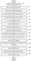
- Figure 2 is a process flow chart showing certain steps of an embodiment of maintenance and/or repair procedure for a liquid ring pump.
- the maintenance and/or repair procedure is performed on the liquid ring pump 2 shown in Figure 1 and described in more detail earlier above.
- the maintenance and/or repair procedure is described as being performed on the first end portion 16 of the liquid ring pump 2 only.
- the below described maintenance and/or repair procedure may be performed at other areas of the liquid ring pump 2 instead of or in addition to being performed at the first end portion 16.
- the maintenance and/or repair procedure is performed on the second end portion 18 of the liquid ring pump 2 instead of or in addition to being performed at the first end portion 16.
- the maintenance and/or repair procedure being performed at the second end portion 18 may be performed in series, in parallel, or partially overlapping temporally with the maintenance and/or repair procedure being performed at the first end portion 16.
- the maintenance and/or repair procedure performed at the second end portion 18 may be performed to inspect, clean, maintain, or replace liquid ring pump one or more components located at the second end portion 18 selected from the group of components comprising the second mechanical seal 28, the second bearing assembly 30, the second bearing cover 32, the lantern ring 34, washers, seals, bearings, bolts, coupling mechanisms, V-rings, and circlips.
- a user i.e. a human that is performing the maintenance and/or repair procedure removes the first bearing cover 26 from the liquid ring pump 2.
- Figure 3 is a schematic illustration (not to scale) showing the first bearing cover 26 being removed from the liquid ring pump 2.
- the first bearing cover 26 is attached to the housing 4 at the first end portion 16 by a first plurality of bolts 36.
- the user removes from the liquid ring pump 2 the first plurality of bolts 36, followed by the first bearing cover 26, as indicated in Figure 3 by solid arrows and the reference numeral 38.
- step s4 the user removes the first bearing assembly 24 from the liquid ring pump 2.
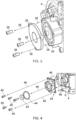
- Figure 4 is a schematic illustration (not to scale) showing the first bearing assembly 24 being removed from the liquid ring pump 2.
- the first bearing assembly 24 fits around the shaft 8 and attaches to the housing 4 at the first end portion 16 by a second plurality of bolts 40.
- a first washer 42 and a first spacer 44 are coupled to an end of the shaft 8 between the first bearing assembly 24 and the first bearing cover 26.
- the user removes from the liquid ring pump 2, in turn, the second plurality of bolts 40, the first washer 42 and the first spacer 44, and the first bearing assembly 24, as indicated in Figure 4 by solid arrows and the reference numeral 46.
- the user reconditions the first bearing assembly 24 if required. For example, the user may inspect, clean, repair and/or replace some or all of the components of the first bearing assembly 24 that has been removed from the liquid ring pump 2. In some embodiments, the user replaces the first bearing assembly 24 with a new bearing assembly.
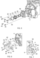
- Figure 5 is a schematic illustration (not to scale) showing an exploded view of the first bearing assembly 24.
- the first bearing assembly 24 comprises a second washer 50, a second spacer 52, a bearing 54, a bearing spacer 56, a lip seal 58, and a bearing assembly housing 60.
- the user may disassemble some or all of the first bearing assembly 24 to perform maintenance, inspection, cleaning, repair or replacement.
- the user may inspect, clean, repair, and/or replace one or more of the component parts 50-60 of the first bearing assembly 24 prior to reassembling the first bearing assembly 24, thereby to provide a reconditioned first bearing assembly 24.
- step s6 the user attaches a fixing bracket to the liquid ring pump 2 (which has had the first bearing cover 26 and first bearing assembly 24 removed).
- Figure 6 is a schematic illustration (not to scale) illustrating the fixing bracket 62 being attached to the liquid ring pump 2.
- the fixing bracket 62 is made of a metal.
- the fixing bracket 62 comprises a square U-shaped central portion having a base member 64 and two side members 66 extending substantially perpendicularly from opposite ends of the base member 64.
- the fixing bracket 62 further comprises two arms 68.
- Each arm 68 is attached to a respective side member 66, at the opposite end of that side member 66 to the base member 64.
- the arms 68 extend outwards from the side members 66 substantially parallel to the base member 64.
- the fixing bracket 62 comprises three holes, namely a first hole 71, a second hole 72, and a third hole 73.
- the first hole 71 passes through the base member 64 substantially equidistant between the ends of the base member 64.
- the second and third holes 72, 73 each pass through a respective arm 68 of the fixing bracket 62.
- the fixing bracket 62 is attached to liquid ring pump 2 via three bolts, namely a first bolt 81, a second bolt 82, and a third bolt 83.
- the first bolt 81 passes through the first hole 71 in the base member 64, and into a bore in the first end of the shaft 8, thereby fixedly attaching the base member 64 to the shaft 8.
- the second bolt 82 passes through the second hole 72 of the fixing bracket 62 and into a bore in the housing 4, thereby fixedly attaching an arm 68 of the fixing bracket 62 to the housing 4.
- the third bolt 83 passes through the third hole 73 of the fixing bracket 62 and into a bore in the housing 4, thereby fixedly attaching an arm 68 of the fixing bracket 62 to the housing 4.
- the bores in the housing 4 into which the second and third bolts 82, 83 are inserted are the same bores as those used by two bolts from the first or second pluralities of bolts 36, 40 (which were removed earlier in the process of Figure 2 ).
- Figure 7 is a schematic illustration (not to scale) illustrating the fixing bracket 62 attached to the liquid ring pump 2.
- the fixing bracket 62 fixedly attaches the shaft 8 to the housing 4 such that relative movement therebetween is prevented or opposed.
- the fixing bracket 62 prevents the shaft 8 from rotating about its axis, i.e. the fixing bracket 62 prevents rotation of the shaft 8 relative to the housing 4.
- the fixing bracket 62 prevents axial movement of the shaft 8 relative to the housing 4.
- the fixing bracket 62 prevents radial movement of the shaft 8 relative to the housing 4.
- the user removes (e.g. detaches or decouples) the first mechanical seal 22 from the housing 4.
- Figure 8 is a schematic illustration (not to scale) illustrating removal of the first mechanical seal 22 from the housing 4.
- the first mechanical seal 22 is detached from the housing 4 and slid along the shaft 8 from the housing 4 towards the fixing bracket 62.
- the first mechanical seal 22 is moved such that it is spaced apart from the housing 4.
- This removal of the first mechanical seal 22 from the housing 4 is indicated in Figure 8 by solid arrows and the reference numeral 86.
- the user couples a support member between the shaft 8 and the surface upon which the liquid ring pump 2 is installed (e.g. the ground).
- Figure 9 is a schematic illustration (not to scale) showing the support member 90 coupled between the shaft 8 and the surface 92 upon which the liquid ring pump 2 is installed.
- the liquid ring pump is attached (e.g. by bolts) to the surface 92.
- the support member 90 is an elongate metal member.
- the support member 90 is coupled to the shaft 8 at a position along the shaft 8 between the first mechanical seal 22 and the housing 4. Thus, the support member 90 does not impede the later removal of the first mechanical seal 22 from the first end of the shaft 8.
- the support member 90 fixedly couples the shaft 8 to the surface 92 onto which the housing 4 is secured.
- the shaft 8 is securely coupled to the housing via the support member 90.
- the support member 90 prevents the shaft 8 from rotating about its axis, i.e. the support member 90 prevents rotation of the shaft 8 relative to the housing 4.
- the support member 90 prevents axial movement of the shaft 8 relative to the housing 4.
- the support member 90 prevents radial movement of the shaft 8 relative to the housing 4.
- the user removes the fixing bracket 62 from the liquid ring pump 2.
- the fixing bracket 62 is detached from the end of the shaft 8 and from the housing 4.
- step s14 the user removes the first mechanical seal 22 from the shaft 8.
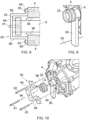
- Figure 10 is a schematic illustration (not to scale) illustrating the fixing bracket 62 and the first mechanical seal 22 being removed from the liquid ring pump 2.
- the user removes from the liquid ring pump 2 the first, second, and third bolts 81, 82, 83, followed by the fixing bracket 62, followed by the first mechanical seal 22, as indicated in Figure 10 by solid arrows and the reference numeral 94.
- the user reconditions the mechanical seal 22 if required. For example, the user may inspect, clean repair and/or replace some or all of the components of the first mechanical seal 22. In some embodiments, the user may replace the first mechanical seal 22 with a new mechanical seal.
- step s16 the user places the reconditioned mechanical seal onto the first end of the shaft 8 outward of the support member 90.
- the user attaches the fixing bracket 62 to the liquid ring pump 2 (which has the first bearing cover 26 and assembly 24 removed).
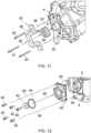
- FIG 11 is a schematic illustration (not to scale) illustrating the reconditioned first mechanical seal 22' and the fixing bracket 62 being attached to the liquid ring pump 2.
- the reconditioned mechanical seal 22' is first placed onto the first end of the shaft 8, and the fixing bracket 62 is subsequently attached to the shaft 8 and the housing 4 by the first, second, and third bolts 81, 82, 83 in the same way as performed at step s6 (and described in more detail earlier above with reference to Figure 6 ).
- the reconditioned first mechanical seal 22' is thus located between the fixing bracket 62 and the support member 90.
- This attachment of the reconditioned first mechanical seal 22' and the fixing bracket 62 to the liquid ring pump 2 is indicated in Figure 11 by solid arrows and the reference numeral 96.
- the user removes the support member 90 from between the shaft 8 and the surface 92.
- the support member 90 is decoupled from the shaft 8. Relative positions of the shaft 8 and the housing 4 are maintained by the fixing bracket 62.
- the user installs the reconditioned first mechanical seal 22' in the liquid ring pump 2.
- the reconditioned first mechanical seal 22' is slid along the shaft 8 into the housing 4.
- the reconditioned first mechanical seal 22' is then coupled between the housing 4 and shaft 8 in the same way as it was before it was removed and reconditioned at step s14 and s15 respectively.
- the user removes the fixing bracket 62 from the liquid ring pump 2.
- the fixing bracket 62 is detached from the end of the shaft 8 and from the housing 4. Correct positioning between the shaft and the housing 4 is provided by the reconditioned first mechanical seal 22'.
- step s26 the user attaches the reconditioned first bearing assembly 24 to the liquid ring pump 2.
- Figure 12 is a schematic illustration (not to scale) showing the reconditioned first bearing assembly 24' being attached to the liquid ring pump 2.
- the reconditioned first bearing assembly 24' fits around the shaft 8 and attaches to the housing 4 at the first end portion 16 by the second plurality of bolts 40.
- the reconditioned first bearing assembly 24' is coupled to the housing 4 and shaft 8 in the same way as it was before it was removed and reconditioned at steps s4 and s5 respectively.
- the first washer 42 and the first spacer 44 are coupled to the first end of the shaft 8 in the same way as they were before they were removed at step s4.
- the first washer 42 and/or the first spacer 44 are reconditioned (e.g. cleaned or repaired) prior to reattachment to the liquid ring pump 2.
- the first washer 42 and/or the first spacer 44 are replaced by new parts which are then attached to the liquid ring pump 2.
- step s26 the user reattaches the first bearing cover 26 to the liquid ring pump 2.
- the first bearing cover 26 is reattached to the housing 4 at the first end portion 16 by the first plurality of bolts 36.
- the first bearing cover 26 is coupled to the housing 4 and shaft 8 in the same way as it was before it was removed at step s2.
- the first bearing cover 26 is reconditioned (e.g. cleaned or repaired) prior to reattachment to the liquid ring pump 2. In some embodiments, the first bearing cover 26 is replaced by a new part which is then attached to the liquid ring pump 2.
- the above-described maintenance and/or repair procedure may be performed while the shaft of the liquid ring pump is substantially horizontal, e.g. substantially parallel to the surface upon which the liquid ring pump is installed.
- maintenance and/or repair of the liquid ring pump may be performed with the liquid ring pump in its installed state.
- the shaft is secured in its substantially horizontal position such that movement of the shaft relative to the housing is prevented or opposed. This tends to reduce the likelihood of components of the liquid ring pump being damaged during the procedure. For example, undesirable bending of the shaft which may damage the shaft tends to be reduced or eliminated.
- the likelihood of the impeller vanes mounted to the shaft impacting the walls of the housing, which may damage the vanes and/or housing tends to be reduced or eliminated.
- the above-described maintenance and/or repair procedure tends to avoid the conventionally implemented process of suspending the liquid ring pump above the ground, and rotating it through about 90° so that the shaft is substantially vertical.
- a need for apparatus for lifting, rotating, and suspending the liquid ring pump tends to be avoided.
- a risk that component parts disassembled or loosened during maintenance fall from the liquid ring pump and become damaged is reduced or eliminated. This further tends to improve the safety of personnel carrying out maintenance or repair of the liquid ring pump.
- the above-described maintenance and/or repair procedure tends to provide for faster maintenance and/or repair of a liquid ring pump compared to conventional techniques.
- the maintenance and/or repair procedure is implemented on a single stage liquid ring pump.
- the maintenance and/or repair procedure is implemented on a different type of liquid ring pump, e.g. a multi-stage liquid ring pump.
- the maintenance and/or repair procedure is implemented on a liquid ring pump that has different components to those described above, or components that may be arranged or connected together in a different way.
- the maintenance and/or repair procedure may be performed to inspect, clean, maintain, repair or replace liquid ring pump components including but not limited to the first mechanical seal, the first bearing assembly, the first bearing cover, and/or washers and seals located at the first end portion.
- inspection, cleaning, maintaining, or replacement of one or more other liquid ring pump components is performed instead of or in addition to those described above, for example, coupling mechanisms, housings, washers, spacers, seals, bearings, belts, belt drives, V-rings, circlips, bolts, and nuts.
- the fixing bracket is made of metal.
- the fixing bracket comprises a different material instead of or in addition to metal.
- the fixing bracket comprises a square U-shaped central portion with two arms extending from the end of that square U-shaped central portion.
- the fixing bracket has a different shape.
- the fixing bracket attaches to the shaft and the housing via three bolts which pass through respective holes in the fixing bracket.
- the fixing bracket is fixedly attached to the shaft and/or the housing in a different appropriate way, for example, via a different number of bolts.
- the fixing bracket may have a different number of holes for receiving a different number of bolts.
- the fixing bracket is attached between an end of the shaft and the housing, thereby to prevent or oppose relative movement of the shaft and housing.
- a support member or other structure is attached between the end of the shaft and the surface upon which the liquid ring pump is installed (e.g. the ground), thereby to prevent or oppose relative movement of the shaft and housing.
- the support member is made of metal.
- the support member comprises a different material instead of or in addition to metal.
- the support member is an elongate member.
- the support member has a different shape.
- the support member is attached between the shaft and the surface upon which the liquid ring pump is installed, thereby to prevent or oppose relative movement of the shaft and housing.
- the support member is coupled to the shaft at an intermediate position along the length of the shaft between the first mechanical seal and the housing.
- relative movement of the shaft and housing is prevented or opposed in a different way.
- a fixing member is attached directly between the shaft and the housing, thereby to prevent or oppose relative movement of the shaft and housing.
- the fixing member may attach to the shaft at the intermediate position along the length of the shaft between the first mechanical seal and the housing.
- many of the above described method steps are performed by a human user using any appropriate tools.
- one or more of the above described method steps is performed by a different entity, for example a computer-controlled robot arm.
- the mechanical seal is removed from the liquid ring pump at an end of the shaft.
- the mechanical seal is not removed from the liquid ring pump.
- a maintenance operation e.g. cleaning or repair
- steps s10-s14 and s16-s20 may be omitted from the maintenance and/or repair procedure.
- a maintenance operation is performed on the housing of the liquid ring pump, or on a component on or within the housing that is accessible by virtue of the mechanical seal being spaced apart from the housing.
Landscapes
- Engineering & Computer Science (AREA)
- Mechanical Engineering (AREA)
- General Engineering & Computer Science (AREA)
- Structures Of Non-Positive Displacement Pumps (AREA)
Description
- The present invention relates to methods and apparatus for decoupling liquid ring pump components from liquid ring pumps, for example to enable or facilitate maintenance services to be performed on the liquid ring pump and components thereof.
- Liquid ring pumps are a known type of pump. Liquid ring pumps typically include a housing that defines a chamber, a shaft passing into the chamber, an impeller mounted to the shaft, and a drive system such as a motor operably connected to the shaft to drive the shaft. The impeller and shaft are positioned eccentrically within the chamber.
- In operation, the chamber is partially filled with an operating liquid. When the drive system drives the shaft and the impeller, a liquid ring is formed on the inner wall of the chamber thus providing a seal that isolates individual volumes between adjacent impeller vanes. The impeller and shaft are eccentric to the liquid ring. This results in a cyclic variation of the volumes enclosed between adjacent vanes of the impeller and the liquid ring.
- In a portion of the chamber where the liquid ring is further away from the shaft, there is a larger volume between adjacent impeller vanes which results in a smaller pressure therein. This allows the portion where the liquid ring is further away from the shaft to act as a gas intake zone. In a portion of the chamber where the liquid ring is closer to the shaft, there is a smaller volume between adjacent impeller vanes which results in a larger pressure therein. This allows the portion where the liquid ring is closer to the impeller to act a gas discharge zone.
- Examples of liquid ring pumps include single-stage liquid ring pumps and multi-stage liquid ring pumps. Single-stage liquid ring pumps involve the use of only a single chamber and impeller. Multi-stage liquid ring pumps (e.g. two-stage) involve the use of multiple chambers connected in series.
- Preferably, liquid ring pumps undergo maintenance procedures. For example, pump bearings may be periodically lubricated. Also, liquid ring pumps may be regularly cleaned to remove solid matter (such as dirt, sand, or lime deposits) that has entered and collected in the liquid ring pump through the operating liquid and/or the pumped gases.
- Also, liquid ring pumps may undergo repair procedures to repair or replace damaged or failed components. Components of the liquid ring pump, including but not limited to bearings, belt drives, and seals, may become damaged or fail, for example, as a result of cavitation, erosion, and/or corrosion.
-
US 2013/0290251 A1 discloses the installation of a mechanical seal in a liquid ring pump. - Typically, a liquid ring pump is installed such that, in operation, the shaft of the liquid ring pump is substantially horizontal (e.g. substantially parallel with a surface upon which the liquid ring pump is located or installed). Maintenance and/or repair procedures for a liquid ring pump tend to involve disassembly or loosening of at least part of the liquid ring pump. However, conventionally, such disassembly of the liquid ring pump while the shaft is oriented horizontally tends to risk unwanted bending of the shaft. Such bending of the shaft may damage the shaft and may also cause the impeller vanes to collide with the walls of the housing, which may damage the vanes and/or housing.
- Conventionally, to alleviate this problem, maintenance and/or repair procedures typically include suspending the liquid ring pump above the ground, and rotating it through about 90° so that its shaft is substantially vertical. Maintenance and/or repair of the liquid ring pump, including partial disassembly, are then performed.
- However, apparatus for lifting, rotating, and suspending a liquid ring pump is large and costly. Furthermore, there tends to be an increased likelihood that component parts disassembled or loosened during maintenance may fall from the suspended liquid ring pump and become damaged.
- The present inventors have realised that it would be beneficial to provide a maintenance or repair procedure for a liquid ring pump that may be implemented while the shaft of the liquid ring pump is oriented horizontally, and which also reduces or eliminates unwanted shaft bending. The present inventors have further realised that it would be beneficial to provide a way of at least partially disassembling a liquid ring pump while the shaft of the pump is oriented horizontally in a way that reduces or eliminates unwanted shaft bending.
- The present inventors have realised that it would be beneficial to provide a maintenance or repair procedure for a liquid ring pump that avoids lifting, rotating, and suspending above the ground the liquid ring pump.
- In a first aspect, the present invention provides a method for decoupling a liquid ring pump component from a liquid ring pump. The liquid ring pump comprises a housing defining an annular chamber and a shaft passing into the chamber. The liquid ring pump component is disposed around the shaft and coupled between the shaft and the housing. The method comprises: coupling, using a first fixing member, a first end of the shaft to the housing thereby to prevent or oppose movement of the shaft relative to the housing in at least a radial direction; and, thereafter, sliding the component along the shaft in a direction along the shaft from the housing towards the first end of the shaft, thereby spacing apart the housing and the component.
- The liquid ring pump component may be configured to, when the liquid ring pump component is disposed around the shaft and coupled between the shaft and the housing, prevent or oppose movement of the shaft relative to the housing in a radial direction and/or axial direction.
- An impeller comprising a plurality of impeller blades or vanes may be mounted to the shaft and located within the chamber such that rotation of the shaft causes the impeller to rotate within the chamber.
- The method may further comprise, while the component and the housing are spaced apart, inspecting, cleaning, repairing or replacing the component or a further component of the liquid ring pump. The method may further comprise sliding the component along the shaft in a direction along the shaft from the first end of the shaft towards the housing, and coupling the component between the shaft and the housing.
- The first fixing member may be a member selected from the group of members consisting of: a fixing bracket configured to fixedly attach between the first end of the shaft and the housing, and a support member configured to be coupled between the shaft and a surface upon which the liquid ring pump is located.
- The first fixing member may be a bracket comprising a base member, two side members extending substantially perpendicularly from opposite ends of the base member, and two arms, each arm being attached to a respective side member at the opposite end of that side member to the base member, the arms extending outwards from the side members substantially parallel to the base member. Coupling the first end of the shaft to the housing may comprise bolting the fixing bracket to the shaft and the housing. Bolting the fixing bracket to the shaft and the housing may comprise inserting a bolt into a hole in the housing, the hole being a hole via which a bearing assembly or bearing assembly cover is bolted to the liquid ring pump.
- The method may further comprise coupling, using a second fixing member, the shaft to the housing. The second fixing member may be configured to prevent or oppose movement of the shaft relative to the housing in at least a radial direction. The second fixing member may be coupled to the shaft at a position along the length of the shaft that is further away from the first end than the component. The method may further comprise decoupling the first fixing member from the first end of the shaft, and removing the component from the shaft at the first end of the shaft. The method may further comprise: inspecting, cleaning, repairing or replacing the removed component, thereby to provide a reconditioned or replacement component; disposing the reconditioned or replacement component around the shaft at the first end of the shaft; coupling, using a fixing member, a first end of the shaft to the housing, the fixing member configured to prevent or oppose movement of the shaft relative to the housing in at least a radial direction; decoupling the second fixing member from the shaft; sliding the reconditioned or replacement component along the shaft in a direction along the shaft from the first end of the shaft towards the housing; coupling the reconditioned or replacement component between the shaft and the housing; and, thereafter, decoupling the fixing member from the first end of the shaft.
- The second fixing member may be a member selected from the group of members consisting of: a fixing bracket configured to fixedly attach between the shaft and the housing, and a support member configured to be coupled between the shaft and a surface upon which the liquid ring pump is located.
- The component may be a mechanical seal.
- The method may further comprise: prior to coupling the first end of the shaft to the housing using the first fixing member, removing, from the liquid ring pump at or proximate to the first end of the shaft, one or more liquid ring pump components selected from the group of components consisting of: a bearing cover, a bolt, a spacer, a washer, a bearing assembly, a bearing, a seal, a lantern ring, a V-ring, and a circlip. The method may further comprise inspecting, cleaning, repairing or replacing the removed one or more liquid ring pump components, thereby to provide a reconditioned or replacement one or more liquid ring pump components.
- Coupling, using the first fixing member, the first end of the shaft to the housing may further prevent or oppose axial and/or rotational movement of the shaft relative to the housing.
- The shaft may be retained in a substantially horizonal orientation during the method. The term "horizontal" may refer to being parallel to the plane of the horizon, or parallel to the plane of a surface upon which the liquid ring pump is located or installed.
- The method may further comprise: coupling, using a third fixing member, a second end of the shaft to the housing thereby to prevent or oppose movement of the shaft relative to the housing in at least a radial direction, the second end of the shaft being opposite to the first end; and, thereafter, sliding a further component along the shaft in a direction along the shaft from the housing towards the second end of the shaft, thereby spacing apart the housing and the component. The steps of coupling the second end of the shaft to the housing and sliding the further component along the shaft towards the second end of the shaft may overlap temporally at least to some extent with the steps of coupling the first end of the shaft to the housing and sliding the component along the shaft towards the first end of the shaft.
- In a further aspect, the present invention provides a system comprising: a liquid ring pump comprising a housing defining an annular chamber, a shaft coupled to the housing and passing through the housing into the chamber, and a component disposed around the shaft and coupled between the shaft and the housing and configured to prevent or oppose movement of the shaft relative to the housing in at least a radial direction; and a fixing member configured to couple together a first end of the shaft and the housing thereby to prevent or oppose movement of the shaft relative to the housing in at least the radial direction.
-
-
Figure 1 is a schematic illustration (not to scale) of a liquid ring pump; -
Figure 2 is a process flow chart showing certain steps of a maintenance and/or repair procedure for the liquid ring pump; -
Figure 3 is a schematic illustration (not to scale) showing a bearing cover being removed from the liquid ring pump; -
Figure 4 is a schematic illustration (not to scale) showing a bearing assembly being removed from the liquid ring pump; -
Figure 5 is a schematic illustration (not to scale) showing an exploded view of the bearing assembly; -
Figure 6 is a schematic illustration (not to scale) illustrating a fixing bracket being attached to the liquid ring pump; -
Figure 7 is a schematic illustration (not to scale) illustrating the fixing bracket attached to the liquid ring pump; -
Figure 8 is a schematic illustration (not to scale) illustrating removal of a mechanical seal from a housing of the liquid ring pump; -
Figure 9 is a schematic illustration (not to scale) showing a support member coupled to the liquid ring pump; -
Figure 10 is a schematic illustration (not to scale) illustrating the fixing bracket and the mechanical seal being removed from the liquid ring pump; -
Figure 11 is a schematic illustration (not to scale) illustrating a reconditioned mechanical seal and the fixing bracket being attached to the liquid ring pump; and -
Figure 12 is a schematic illustration (not to scale) showing a reconditioned bearing assembly being attached to the liquid ring pump. -
Figure 1 is a schematic illustration (not to scale) of an example single stageliquid ring pump 2 that will be used to illustrate an embodiment of a maintenance and/or repair procedure. - The
liquid ring pump 2 comprises ahousing 4 that defines a substantially cylindrical chamber 6, ashaft 8 extending into the chamber 6, and animpeller 10 fixedly mounted to theshaft 8. Theliquid ring pump 2 further comprises agas inlet 12 fluidly connected to a gas intake of the chamber 6, and a gas outlet (not shown in the Figures) fluidly connected to a gas output of the chamber 6. - During operation of the
liquid ring pump 2, theshaft 8 rotates thereby rotating theimpeller 10 within the chamber 6. As theimpeller 10 rotates, an operating liquid (not shown in the Figures) is forced against the walls of the chamber 6 thereby to form a liquid ring that seals and isolates individual volumes between adjacent impeller vanes. Also, gas 14 (such as air) is drawn into the chamber 6 via theinlet 12 and the gas intake of the chamber 6. This gas flows into the volumes formed between adjacent vanes of theimpeller 10. The rotation of theimpeller 10 compresses the gas contained within the volume as it is moved from the gas intake of the chamber 6 to the gas output of the chamber 6, where the compressed gas exits the chamber 6. - The
housing 4 comprises afirst end portion 16, asecond end portion 18, and acentral portion 20 disposed between the first andsecond end portions second end portions central portion 20. - The chamber 6 is defined by interior walls of the
central portion 20 of thehousing 4. The longitudinal axis of theshaft 8 is offset, i.e. eccentric, relative to the axis of thecentral portion 20. - The
first end portion 16 comprises a firstmechanical seal 22 disposed between theshaft 8 and the walls of the chamber 6. The firstmechanical seal 22 forms a seal between theshaft 8 and the walls of the chamber 6 thereby to prevent or oppose leakage of the gas and operating liquid out of the chamber 6 at thefirst end portion 16. The firstmechanical seal 22 is arranged to prevent or oppose radial movement of theshaft 8, i.e. in a direction that is substantially perpendicular to the longitudinal axis of theshaft 8. The firstmechanical seal 22 may prevent or oppose axial movement of theshaft 8. The firstmechanical seal 22 is configured to permit rotation of theshaft 8 about its longitudinal axis. - The
first end portion 16 further comprises afirst bearing assembly 24 disposed around theshaft 8 and axially outward of the firstmechanical seal 22. Thefirst end portion 16 further comprises afirst bearing cover 26 which houses thefirst bearing assembly 24 and covers a first end of theshaft 8 at thefirst end portion 16. Thefirst bearing cover 26 is at the outboard end of theliquid ring pump 2. - The
second end portion 18 comprises a secondmechanical seal 28 disposed between theshaft 8 and the walls of the chamber 6. The secondmechanical seal 28 forms a seal between theshaft 8 and the walls of the chamber 6 thereby to prevent or oppose leakage of the gas and operating liquid out of the chamber 6 at thesecond end portion 18. The secondmechanical seal 28 is arranged to prevent or oppose radial movement of theshaft 8, i.e. in a direction that is substantially perpendicular to the longitudinal axis of theshaft 8. The secondmechanical seal 28 may prevent or oppose axial movement of theshaft 8. The secondmechanical seal 28 is configured to permit rotation of theshaft 8 about its longitudinal axis. - The
second end portion 18 further comprises asecond bearing assembly 30 disposed around theshaft 8 and axially outward of the secondmechanical seal 28. Thesecond end portion 18 further comprises asecond bearing cover 32 which houses thesecond bearing assembly 30 and covers a second end of the shaft 8 (opposite to the first end of the shaft 8) at thesecond end portion 18. - The
second end portion 18 further comprises alantern ring 34 coupled to thehousing 4 and around theshaft 8, thesecond bearing assembly 30, and thesecond bearing cover 32. Thelantern ring 34 is a perforated hollow ring that, in operation, is used to couple the pump to the motor, supports the motor and the drive end casing, to the base frame. -
Figure 2 is a process flow chart showing certain steps of an embodiment of maintenance and/or repair procedure for a liquid ring pump. In this embodiment, the maintenance and/or repair procedure is performed on theliquid ring pump 2 shown inFigure 1 and described in more detail earlier above. - In this embodiment, for the sake of brevity, the maintenance and/or repair procedure is described as being performed on the
first end portion 16 of theliquid ring pump 2 only. However, it will be appreciated by those skilled in the art that the below described maintenance and/or repair procedure may be performed at other areas of theliquid ring pump 2 instead of or in addition to being performed at thefirst end portion 16. For example, in other embodiments the maintenance and/or repair procedure is performed on thesecond end portion 18 of theliquid ring pump 2 instead of or in addition to being performed at thefirst end portion 16. The maintenance and/or repair procedure being performed at thesecond end portion 18 may be performed in series, in parallel, or partially overlapping temporally with the maintenance and/or repair procedure being performed at thefirst end portion 16. The maintenance and/or repair procedure performed at thesecond end portion 18 may be performed to inspect, clean, maintain, or replace liquid ring pump one or more components located at thesecond end portion 18 selected from the group of components comprising the secondmechanical seal 28, thesecond bearing assembly 30, thesecond bearing cover 32, thelantern ring 34, washers, seals, bearings, bolts, coupling mechanisms, V-rings, and circlips. - At step s2, a user (i.e. a human that is performing the maintenance and/or repair procedure) removes the first bearing cover 26 from the
liquid ring pump 2. -
Figure 3 is a schematic illustration (not to scale) showing thefirst bearing cover 26 being removed from theliquid ring pump 2. In this embodiment, thefirst bearing cover 26 is attached to thehousing 4 at thefirst end portion 16 by a first plurality ofbolts 36. At step s2, the user removes from theliquid ring pump 2 the first plurality ofbolts 36, followed by thefirst bearing cover 26, as indicated inFigure 3 by solid arrows and thereference numeral 38. - At step s4, the user removes the
first bearing assembly 24 from theliquid ring pump 2. -
Figure 4 is a schematic illustration (not to scale) showing thefirst bearing assembly 24 being removed from theliquid ring pump 2. In this embodiment, thefirst bearing assembly 24 fits around theshaft 8 and attaches to thehousing 4 at thefirst end portion 16 by a second plurality ofbolts 40. Afirst washer 42 and afirst spacer 44 are coupled to an end of theshaft 8 between thefirst bearing assembly 24 and thefirst bearing cover 26. At step s4, the user removes from theliquid ring pump 2, in turn, the second plurality ofbolts 40, thefirst washer 42 and thefirst spacer 44, and thefirst bearing assembly 24, as indicated inFigure 4 by solid arrows and thereference numeral 46. - At step s5, the user reconditions the
first bearing assembly 24 if required. For example, the user may inspect, clean, repair and/or replace some or all of the components of thefirst bearing assembly 24 that has been removed from theliquid ring pump 2. In some embodiments, the user replaces thefirst bearing assembly 24 with a new bearing assembly. -
Figure 5 is a schematic illustration (not to scale) showing an exploded view of thefirst bearing assembly 24. In this embodiment, thefirst bearing assembly 24 comprises asecond washer 50, asecond spacer 52, abearing 54, a bearingspacer 56, alip seal 58, and a bearingassembly housing 60. The user may disassemble some or all of thefirst bearing assembly 24 to perform maintenance, inspection, cleaning, repair or replacement. The user may inspect, clean, repair, and/or replace one or more of the component parts 50-60 of thefirst bearing assembly 24 prior to reassembling thefirst bearing assembly 24, thereby to provide a reconditioned first bearingassembly 24. - At step s6, the user attaches a fixing bracket to the liquid ring pump 2 (which has had the
first bearing cover 26 andfirst bearing assembly 24 removed). -
Figure 6 is a schematic illustration (not to scale) illustrating the fixingbracket 62 being attached to theliquid ring pump 2. - In this embodiment, the fixing
bracket 62 is made of a metal. - In this embodiment, the fixing
bracket 62 comprises a square U-shaped central portion having abase member 64 and twoside members 66 extending substantially perpendicularly from opposite ends of thebase member 64. The fixingbracket 62 further comprises twoarms 68. Eacharm 68 is attached to arespective side member 66, at the opposite end of thatside member 66 to thebase member 64. Thearms 68 extend outwards from theside members 66 substantially parallel to thebase member 64. - In this embodiment, the fixing
bracket 62 comprises three holes, namely afirst hole 71, asecond hole 72, and athird hole 73. Thefirst hole 71 passes through thebase member 64 substantially equidistant between the ends of thebase member 64. The second andthird holes respective arm 68 of the fixingbracket 62. - The fixing
bracket 62 is attached toliquid ring pump 2 via three bolts, namely afirst bolt 81, asecond bolt 82, and athird bolt 83. - The
first bolt 81 passes through thefirst hole 71 in thebase member 64, and into a bore in the first end of theshaft 8, thereby fixedly attaching thebase member 64 to theshaft 8. Thesecond bolt 82 passes through thesecond hole 72 of the fixingbracket 62 and into a bore in thehousing 4, thereby fixedly attaching anarm 68 of the fixingbracket 62 to thehousing 4. Thethird bolt 83 passes through thethird hole 73 of the fixingbracket 62 and into a bore in thehousing 4, thereby fixedly attaching anarm 68 of the fixingbracket 62 to thehousing 4. This attachment of the fixingbracket 62 to theshaft 8 and thehousing 4 via the first, second, and third bolts 81-83 is indicated inFigure 6 by solid arrows and thereference numeral 84. Preferably, the bores in thehousing 4 into which the second andthird bolts bolts 36, 40 (which were removed earlier in the process ofFigure 2 ). -
Figure 7 is a schematic illustration (not to scale) illustrating the fixingbracket 62 attached to theliquid ring pump 2. In this embodiment, the fixingbracket 62 fixedly attaches theshaft 8 to thehousing 4 such that relative movement therebetween is prevented or opposed. Preferably, the fixingbracket 62 prevents theshaft 8 from rotating about its axis, i.e. the fixingbracket 62 prevents rotation of theshaft 8 relative to thehousing 4. Preferably, the fixingbracket 62 prevents axial movement of theshaft 8 relative to thehousing 4. Preferably, the fixingbracket 62 prevents radial movement of theshaft 8 relative to thehousing 4. - At step s8, the user removes (e.g. detaches or decouples) the first
mechanical seal 22 from thehousing 4. -
Figure 8 is a schematic illustration (not to scale) illustrating removal of the firstmechanical seal 22 from thehousing 4. In this embodiment, the firstmechanical seal 22 is detached from thehousing 4 and slid along theshaft 8 from thehousing 4 towards the fixingbracket 62. Thus, the firstmechanical seal 22 is moved such that it is spaced apart from thehousing 4. This removal of the firstmechanical seal 22 from thehousing 4 is indicated inFigure 8 by solid arrows and thereference numeral 86. - At step s10, the user couples a support member between the
shaft 8 and the surface upon which theliquid ring pump 2 is installed (e.g. the ground). -
Figure 9 is a schematic illustration (not to scale) showing thesupport member 90 coupled between theshaft 8 and thesurface 92 upon which theliquid ring pump 2 is installed. In some embodiments, the liquid ring pump is attached (e.g. by bolts) to thesurface 92. - In this embodiment, the
support member 90 is an elongate metal member. - The
support member 90 is coupled to theshaft 8 at a position along theshaft 8 between the firstmechanical seal 22 and thehousing 4. Thus, thesupport member 90 does not impede the later removal of the firstmechanical seal 22 from the first end of theshaft 8. - The
support member 90 fixedly couples theshaft 8 to thesurface 92 onto which thehousing 4 is secured. Thus, theshaft 8 is securely coupled to the housing via thesupport member 90. Preferably, thesupport member 90 prevents theshaft 8 from rotating about its axis, i.e. thesupport member 90 prevents rotation of theshaft 8 relative to thehousing 4. Preferably, thesupport member 90 prevents axial movement of theshaft 8 relative to thehousing 4. Preferably, thesupport member 90 prevents radial movement of theshaft 8 relative to thehousing 4. - At step s12, the user removes the fixing
bracket 62 from theliquid ring pump 2. In this embodiment, the fixingbracket 62 is detached from the end of theshaft 8 and from thehousing 4. - At step s14, the user removes the first
mechanical seal 22 from theshaft 8. -
Figure 10 is a schematic illustration (not to scale) illustrating the fixingbracket 62 and the firstmechanical seal 22 being removed from theliquid ring pump 2. In this embodiment, at step s14 the user removes from theliquid ring pump 2 the first, second, andthird bolts bracket 62, followed by the firstmechanical seal 22, as indicated inFigure 10 by solid arrows and thereference numeral 94. - At step s15, the user reconditions the
mechanical seal 22 if required. For example, the user may inspect, clean repair and/or replace some or all of the components of the firstmechanical seal 22. In some embodiments, the user may replace the firstmechanical seal 22 with a new mechanical seal. - At step s16, the user places the reconditioned mechanical seal onto the first end of the
shaft 8 outward of thesupport member 90. - At step s18, the user attaches the fixing
bracket 62 to the liquid ring pump 2 (which has thefirst bearing cover 26 andassembly 24 removed). -
Figure 11 is a schematic illustration (not to scale) illustrating the reconditioned first mechanical seal 22' and the fixingbracket 62 being attached to theliquid ring pump 2. In this embodiment, the reconditioned mechanical seal 22' is first placed onto the first end of theshaft 8, and the fixingbracket 62 is subsequently attached to theshaft 8 and thehousing 4 by the first, second, andthird bolts Figure 6 ). The reconditioned first mechanical seal 22' is thus located between the fixingbracket 62 and thesupport member 90. This attachment of the reconditioned first mechanical seal 22' and the fixingbracket 62 to theliquid ring pump 2 is indicated inFigure 11 by solid arrows and thereference numeral 96. - At step s20, the user removes the
support member 90 from between theshaft 8 and thesurface 92. Thus, thesupport member 90 is decoupled from theshaft 8. Relative positions of theshaft 8 and thehousing 4 are maintained by the fixingbracket 62. - At step s22, the user installs the reconditioned first mechanical seal 22' in the
liquid ring pump 2. In this embodiment, the reconditioned first mechanical seal 22' is slid along theshaft 8 into thehousing 4. The reconditioned first mechanical seal 22' is then coupled between thehousing 4 andshaft 8 in the same way as it was before it was removed and reconditioned at step s14 and s15 respectively. - At step s24, the user removes the fixing
bracket 62 from theliquid ring pump 2. In this embodiment, the fixingbracket 62 is detached from the end of theshaft 8 and from thehousing 4. Correct positioning between the shaft and thehousing 4 is provided by the reconditioned first mechanical seal 22'. - At step s26, the user attaches the reconditioned first bearing
assembly 24 to theliquid ring pump 2. -
Figure 12 is a schematic illustration (not to scale) showing the reconditioned first bearing assembly 24' being attached to theliquid ring pump 2. In this embodiment, the reconditioned first bearing assembly 24' fits around theshaft 8 and attaches to thehousing 4 at thefirst end portion 16 by the second plurality ofbolts 40. Thus, the reconditioned first bearing assembly 24' is coupled to thehousing 4 andshaft 8 in the same way as it was before it was removed and reconditioned at steps s4 and s5 respectively. - In this embodiment, the
first washer 42 and thefirst spacer 44 are coupled to the first end of theshaft 8 in the same way as they were before they were removed at step s4. In some embodiments, thefirst washer 42 and/or thefirst spacer 44 are reconditioned (e.g. cleaned or repaired) prior to reattachment to theliquid ring pump 2. In some embodiments, thefirst washer 42 and/or thefirst spacer 44 are replaced by new parts which are then attached to theliquid ring pump 2. - The attachment of the reconditioned first bearing assembly 24', the
first washer 42, and thefirst spacer 44 to theliquid ring pump 2 is indicated inFigure 12 by solid arrows and thereference numeral 98. - At step s26, the user reattaches the
first bearing cover 26 to theliquid ring pump 2. - In this embodiment, the
first bearing cover 26 is reattached to thehousing 4 at thefirst end portion 16 by the first plurality ofbolts 36. Thus, thefirst bearing cover 26 is coupled to thehousing 4 andshaft 8 in the same way as it was before it was removed at step s2. - In some embodiments, the
first bearing cover 26 is reconditioned (e.g. cleaned or repaired) prior to reattachment to theliquid ring pump 2. In some embodiments, thefirst bearing cover 26 is replaced by a new part which is then attached to theliquid ring pump 2. - Thus, a maintenance and/or repair procedure for a liquid ring pump is provided.
- Advantageously, the above-described maintenance and/or repair procedure may be performed while the shaft of the liquid ring pump is substantially horizontal, e.g. substantially parallel to the surface upon which the liquid ring pump is installed. In other words, maintenance and/or repair of the liquid ring pump may be performed with the liquid ring pump in its installed state. During the procedure, the shaft is secured in its substantially horizontal position such that movement of the shaft relative to the housing is prevented or opposed. This tends to reduce the likelihood of components of the liquid ring pump being damaged during the procedure. For example, undesirable bending of the shaft which may damage the shaft tends to be reduced or eliminated. Also, the likelihood of the impeller vanes mounted to the shaft impacting the walls of the housing, which may damage the vanes and/or housing, tends to be reduced or eliminated.
- Furthermore, the above-described maintenance and/or repair procedure tends to avoid the conventionally implemented process of suspending the liquid ring pump above the ground, and rotating it through about 90° so that the shaft is substantially vertical. Thus, a need for apparatus for lifting, rotating, and suspending the liquid ring pump tends to be avoided. Also, a risk that component parts disassembled or loosened during maintenance fall from the liquid ring pump and become damaged is reduced or eliminated. This further tends to improve the safety of personnel carrying out maintenance or repair of the liquid ring pump.
- The above-described maintenance and/or repair procedure tends to require fewer personnel and less equipment compared to conventional techniques.
- The above-described maintenance and/or repair procedure tends to provide for faster maintenance and/or repair of a liquid ring pump compared to conventional techniques.
- It should be noted that certain of the process steps depicted in the flowchart of
Figure 2 and described above may be omitted or such process steps may be performed in differing order to that presented above and shown inFigure 2 . Furthermore, although all the process steps have, for convenience and ease of understanding, been depicted as discrete temporally-sequential steps, nevertheless some of the process steps may in fact be performed simultaneously or at least overlapping to some extent temporally. - In the above embodiments, the maintenance and/or repair procedure is implemented on a single stage liquid ring pump. However, in other embodiments, the maintenance and/or repair procedure is implemented on a different type of liquid ring pump, e.g. a multi-stage liquid ring pump. In some embodiments, the maintenance and/or repair procedure is implemented on a liquid ring pump that has different components to those described above, or components that may be arranged or connected together in a different way.
- In the above embodiments, the maintenance and/or repair procedure may be performed to inspect, clean, maintain, repair or replace liquid ring pump components including but not limited to the first mechanical seal, the first bearing assembly, the first bearing cover, and/or washers and seals located at the first end portion. However, in other embodiments inspection, cleaning, maintaining, or replacement of one or more other liquid ring pump components is performed instead of or in addition to those described above, for example, coupling mechanisms, housings, washers, spacers, seals, bearings, belts, belt drives, V-rings, circlips, bolts, and nuts.
- In the above embodiments, the fixing bracket is made of metal. However, in other embodiments, the fixing bracket comprises a different material instead of or in addition to metal.
- In the above embodiments, the fixing bracket comprises a square U-shaped central portion with two arms extending from the end of that square U-shaped central portion. However, in other embodiments the fixing bracket has a different shape.
- In the above embodiments, the fixing bracket attaches to the shaft and the housing via three bolts which pass through respective holes in the fixing bracket. However, in other embodiments, the fixing bracket is fixedly attached to the shaft and/or the housing in a different appropriate way, for example, via a different number of bolts. The fixing bracket may have a different number of holes for receiving a different number of bolts.
- In the above embodiments, at steps s6 and s18, the fixing bracket is attached between an end of the shaft and the housing, thereby to prevent or oppose relative movement of the shaft and housing. However, in other embodiments, at one or both of these steps, relative movement of the shaft and housing is prevented or opposed in a different way. For example, in some embodiments, at one or both of steps s6 and s18, a support member (or other structure) is attached between the end of the shaft and the surface upon which the liquid ring pump is installed (e.g. the ground), thereby to prevent or oppose relative movement of the shaft and housing.
- In the above embodiments, the support member is made of metal. However, in other embodiments, the support member comprises a different material instead of or in addition to metal.
- In the above embodiments, the support member is an elongate member. However, in other embodiments the support member has a different shape.
- In the above embodiments, at step s10, the support member is attached between the shaft and the surface upon which the liquid ring pump is installed, thereby to prevent or oppose relative movement of the shaft and housing. The support member is coupled to the shaft at an intermediate position along the length of the shaft between the first mechanical seal and the housing. However, in other embodiments, at step s10, relative movement of the shaft and housing is prevented or opposed in a different way. For example, in some embodiments, at steps s10, a fixing member is attached directly between the shaft and the housing, thereby to prevent or oppose relative movement of the shaft and housing. The fixing member may attach to the shaft at the intermediate position along the length of the shaft between the first mechanical seal and the housing.
- In the above embodiments, many of the above described method steps are performed by a human user using any appropriate tools. However, in other embodiments one or more of the above described method steps is performed by a different entity, for example a computer-controlled robot arm.
- In the above embodiments, the mechanical seal is removed from the liquid ring pump at an end of the shaft. However, in other embodiments, the mechanical seal is not removed from the liquid ring pump. For example, in some embodiments, a maintenance operation (e.g. cleaning or repair) may be performed on the mechanical seal while that mechanical seal remains disposed on the shaft. Thus, in some embodiments, steps s10-s14 and s16-s20 may be omitted from the maintenance and/or repair procedure.
- In some embodiments, while the mechanical seal is spaced apart from the housing, a maintenance operation is performed on the housing of the liquid ring pump, or on a component on or within the housing that is accessible by virtue of the mechanical seal being spaced apart from the housing.
Claims (15)
- A method for decoupling a liquid ring pump component from a liquid ring pump, the liquid ring pump comprising a housing defining an annular chamber and a shaft passing into the chamber, the component being disposed around the shaft and coupled between the shaft and the housing, the method comprising:coupling, using a first fixing member, a first end of the shaft to the housing thereby to prevent or oppose movement of the shaft relative to the housing in at least a radial direction; and,thereafter, sliding the component along the shaft in a direction along the shaft from the housing towards the first end of the shaft, thereby spacing apart the housing and the component.
- A method according to claim 1, further comprising:while the component and the housing are spaced apart, inspecting, cleaning, repairing or replacing the component or a further component of the liquid ring pump; and, thereafter,sliding the component along the shaft in a direction along the shaft from the first end of the shaft towards the housing; andcoupling the component between the shaft and the housing.
- A method according to claim 1 or 2, wherein the first fixing member is a member selected from the group of members consisting of: a fixing bracket configured to fixedly attach between the first end of the shaft and the housing, and a support member configured to be coupled between the shaft and a surface upon which the liquid ring pump is located.
- A method according to claim 3, wherein:the first fixing member is a bracket comprising a base member, two side members extending substantially perpendicularly from opposite ends of the base member, and two arms, each arm being attached to a respective side member at the opposite end of that side member to the base member, the arms extending outwards from the side members substantially parallel to the base member; andcoupling the first end of the shaft to the housing comprises bolting the fixing bracket to the shaft and the housing.
- A method according to claim 4, wherein bolting the fixing bracket to the shaft and the housing comprises inserting a bolt into a hole in the housing, the hole being a hole via which a bearing assembly or bearing assembly cover is bolted to the liquid ring pump.
- A method according to any of claims 1 to 5, further comprising:coupling, using a second fixing member, the shaft to the housing, the second fixing member configured to prevent or oppose movement of the shaft relative to the housing in at least a radial direction, wherein the second fixing member is coupled to the shaft at a position along the length of the shaft that is further away from the first end than the component;decoupling the first fixing member from the first end of the shaft; andremoving the component from the shaft at the first end of the shaft.
- A method according to claim 6, further comprising:inspecting, cleaning, repairing or replacing the removed component, thereby to provide a reconditioned or replacement component;disposing the reconditioned or replacement component around the shaft at the first end of the shaft;coupling, using a fixing member, a first end of the shaft to the housing, the fixing member configured to prevent or oppose movement of the shaft relative to the housing in at least a radial direction;decoupling the second fixing member from the shaft;sliding the reconditioned or replacement component along the shaft in a direction along the shaft from the first end of the shaft towards the housing;coupling the reconditioned or replacement component between the shaft and the housing; and,thereafter, decoupling the fixing member from the first end of the shaft.
- A method according to claim 6 or 7, wherein the second fixing member is a member selected from the group of members consisting of: a fixing bracket configured to fixedly attach between the shaft and the housing, and a support member configured to be coupled between the shaft and a surface upon which the liquid ring pump is located.
- A method according to any of claim 1 to 8, wherein the component is a mechanical seal.
- A method according to any of claims 1 to 9, further comprising:prior to coupling the first end of the shaft to the housing using the first fixing member, removing, from the liquid ring pump at or proximate to the first end of the shaft, one or more liquid ring pump components selected from the group of components consisting of: a bearing cover, a bolt, a spacer, a washer, a bearing assembly, a bearing, a seal, a lantern ring, a V-ring, and a circlip; andinspecting, cleaning, repairing or replacing the removed one or more liquid ring pump components, thereby to provide a reconditioned or replacement one or more liquid ring pump components.
- A method according to any of claims 1 to 10, wherein coupling, using the first fixing member, the first end of the shaft to the housing further prevents or opposes axial and/or rotational movement of the shaft relative to the housing.
- A method according to any of claims 1 to 11, wherein the shaft is retained in a substantially horizonal orientation.
- A method according to any of claims 1 to 12, further comprising:coupling, using a third fixing member, a second end of the shaft to the housing thereby to prevent or oppose movement of the shaft relative to the housing in at least a radial direction, the second end of the shaft being opposite to the first end; and,thereafter, sliding a further component along the shaft in a direction along the shaft from the housing towards the second end of the shaft, thereby spacing apart the housing and the component.
- A method according to claim 13, wherein the steps of coupling the second end of the shaft to the housing and sliding the further component along the shaft towards the second end of the shaft overlap temporally at least to some extent with the steps of coupling the first end of the shaft to the housing and sliding the component along the shaft towards the first end of the shaft.
- A system comprising:a liquid ring pump comprising:a housing defining an annular chamber;a shaft coupled to the housing and passing through the housing into the chamber; anda component disposed around the shaft and coupled between the shaft and the housing and configured to prevent or oppose movement of the shaft relative to the housing in at least a radial direction; andthe system being characterised by
a fixing member configured to couple together a first end of the shaft and the housing thereby to prevent or oppose movement of the shaft relative to the housing in at least the radial direction.
Applications Claiming Priority (2)
| Application Number | Priority Date | Filing Date | Title |
|---|---|---|---|
| GB1804110.3A GB2571972B (en) | 2018-03-14 | 2018-03-14 | Method and apparatus related to servicing of liquid ring pumps |
| PCT/IB2019/052065 WO2019175818A1 (en) | 2018-03-14 | 2019-03-14 | Method and apparatus related to servicing of liquid ring pumps |
Publications (3)
| Publication Number | Publication Date |
|---|---|
| EP3765742A1 EP3765742A1 (en) | 2021-01-20 |
| EP3765742A4 EP3765742A4 (en) | 2021-12-15 |
| EP3765742B1 true EP3765742B1 (en) | 2023-05-03 |
Family
ID=61972659
Family Applications (1)
| Application Number | Title | Priority Date | Filing Date |
|---|---|---|---|
| EP19767637.2A Active EP3765742B1 (en) | 2018-03-14 | 2019-03-14 | Method and apparatus related to servicing of liquid ring pumps |
Country Status (5)
| Country | Link |
|---|---|
| US (1) | US20210025390A1 (en) |
| EP (1) | EP3765742B1 (en) |
| CN (1) | CN112105820A (en) |
| GB (1) | GB2571972B (en) |
| WO (1) | WO2019175818A1 (en) |
Families Citing this family (1)
| Publication number | Priority date | Publication date | Assignee | Title |
|---|---|---|---|---|
| CN117989128A (en) * | 2024-02-21 | 2024-05-07 | 广东肯富来泵业股份有限公司 | Horizontal disassembly and assembly method of tie rod structure liquid ring pump |
Family Cites Families (24)
| Publication number | Priority date | Publication date | Assignee | Title |
|---|---|---|---|---|
| GB1154341A (en) * | 1965-10-19 | 1969-06-04 | Edwards High Vacuum Int Ltd | Rotary Pumping Apparatus including a Rotary Vacuum Pump |
| ZA835575B (en) * | 1982-08-13 | 1984-09-26 | Chesterton A W Co | Centrifugal pump |
| CN86203878U (en) * | 1986-05-27 | 1987-05-20 | 金保国 | Circulating chemical process pump |
| US5120206A (en) * | 1991-04-08 | 1992-06-09 | Bridgestone/Firestone, Inc. | Gear metering pump for compounded elastomeric material |
| US5423614A (en) * | 1992-06-26 | 1995-06-13 | Vooner Vacuum Pumps, Inc. | Self aligning removable bearing carrier for a liquid ring vacuum pump |
| JP2604193Y2 (en) * | 1993-11-16 | 2000-04-17 | 株式会社マキタ | Spindle locking mechanism for rotary tools |
| JP2852604B2 (en) * | 1994-05-10 | 1999-02-03 | 江東産業株式会社 | Pulley puller |
| US6543113B1 (en) * | 2000-04-18 | 2003-04-08 | Cummins Engine Company, Inc. | Tooling components for crankshaft seal removal and installation |
| US6622381B2 (en) * | 2001-11-30 | 2003-09-23 | Moyno, Inc. | Method of manipulating a pump |
| EP1477681B1 (en) * | 2003-05-16 | 2006-08-23 | Sterling Fluid Systems (Germany) GmbH | Liquid ring gas pump |
| DE102004052558A1 (en) * | 2004-10-29 | 2006-05-04 | Saurer Gmbh & Co. Kg | gear pump |
| KR200425025Y1 (en) * | 2006-06-19 | 2006-08-28 | 현대제철 주식회사 | Rotor withdrawal jig of vacuum pump |
| US8127417B1 (en) * | 2007-02-26 | 2012-03-06 | American Airlines, Inc. | Bearing assembly removal system and method |
| KR20090046453A (en) * | 2007-11-06 | 2009-05-11 | 현대제철 주식회사 | Rotor take-out jig for vacuum pump |
| US20130209251A1 (en) * | 2012-02-09 | 2013-08-15 | Athanasios Diakomis | Seal arrangement along the shaft of a liquid ring pump |
| JP6037948B2 (en) * | 2013-06-12 | 2016-12-07 | 三菱日立パワーシステムズ株式会社 | Rotating shaft lifting jig and rotating shaft lifting method |
| DE102013108322B4 (en) * | 2013-08-02 | 2015-07-16 | Netzsch Pumpen & Systeme Gmbh | Clamping device and method for stationary fixation of a drive shaft |
| US9541086B2 (en) * | 2013-10-01 | 2017-01-10 | Gardner Denver Nash Llc | Liquid ring pump with modular construction, an inter-stage bypass and overload protection |
| DE102014000846A1 (en) * | 2014-01-27 | 2015-07-30 | Klaus Union Gmbh & Co. Kg | Screw Pump |
| GB201500619D0 (en) * | 2015-01-15 | 2015-03-04 | Rolls Royce Controls & Data Services Ltd | Seal extraction tool |
| CN205261199U (en) * | 2015-12-10 | 2016-05-25 | 合肥凌江汽车焊装有限公司 | Safety device is overhauld to automobile parts welding equipment connecting rod formula |
| CN206668231U (en) * | 2017-04-19 | 2017-11-24 | 大庆市晟威机械制造有限公司 | Directly drive extracting device of oil in a kind of screw pump ground with reverse-rotation preventing function |
| KR101803843B1 (en) * | 2017-08-24 | 2017-12-04 | 주식회사 백콤 | Water ring vacuum pump for component change type |
| CN208416920U (en) * | 2018-07-17 | 2019-01-22 | 克拉玛依红山油田有限责任公司 | Three screw pump fixator |
-
2018
- 2018-03-14 GB GB1804110.3A patent/GB2571972B/en not_active Expired - Fee Related
-
2019
- 2019-03-14 US US16/980,493 patent/US20210025390A1/en not_active Abandoned
- 2019-03-14 WO PCT/IB2019/052065 patent/WO2019175818A1/en not_active Ceased
- 2019-03-14 CN CN201980019125.XA patent/CN112105820A/en active Pending
- 2019-03-14 EP EP19767637.2A patent/EP3765742B1/en active Active
Also Published As
| Publication number | Publication date |
|---|---|
| US20210025390A1 (en) | 2021-01-28 |
| EP3765742A1 (en) | 2021-01-20 |
| EP3765742A4 (en) | 2021-12-15 |
| GB2571972B (en) | 2021-01-20 |
| CN112105820A (en) | 2020-12-18 |
| WO2019175818A1 (en) | 2019-09-19 |
| GB2571972A (en) | 2019-09-18 |
| GB201804110D0 (en) | 2018-04-25 |
Similar Documents
| Publication | Publication Date | Title |
|---|---|---|
| RU2494264C2 (en) | Guide apparatus divided into sectors for turbomachine, low-pressure turbine and turbomachine | |
| US20080034717A1 (en) | Compressed air cleaner utilizing a centrifugal impeller and spiral grooves | |
| CN103917761A (en) | Hot gas expander inlet casing assembly and method | |
| KR20110028337A (en) | Volumetric pump with easy access to common gearbox modules, variable displacement and mechanical seals | |
| JP4260391B2 (en) | Replaceable variable stator blades for gas turbines | |
| US20210025390A1 (en) | Method and apparatus related to servicing of liquid ring pumps | |
| KR101968176B1 (en) | A Mechanical Seal Repair Coupling Device of a Pump | |
| CN105465391A (en) | Rotary valve | |
| AU598027B2 (en) | Centrifugal pump | |
| CN113526334A (en) | Lifting tool, supporting jig, and method of disassembling and assembling rotary machine | |
| CN106168164B (en) | For the system and method close to the blade in turbine | |
| CN204984899U (en) | A high vacuum roots's unit for recovered solvent | |
| US8100627B2 (en) | Pump wet end replacement method and impeller fixing mechanism | |
| US5580222A (en) | Liquid ring vacuum pump and method of assembly | |
| EP0054116B1 (en) | Turbomachine stator assembly, and disassembling and assembling method therefor | |
| US20130284660A1 (en) | Care-free pumped flow rotating drum screen | |
| WO2006096448A2 (en) | Wear ring for a centrifugal pitot tube pump | |
| US20250172159A1 (en) | Centrifugal Pump Casing With Strainer Device Attachment | |
| CN114278580B (en) | Large-scale tubular pump with replaceable guide vanes | |
| CN106687661A (en) | Remanufactured center housing and method | |
| CN216048523U (en) | Drying and filtering device for refrigeration equipment | |
| EP3561225A1 (en) | Method for repairing in-situ installations inside a compressor rear frame case of a gas turbine | |
| RU231406U1 (en) | INDUSTRIAL HIGH PRESSURE FAN | |
| CN101275587B (en) | Centrifugal pump comprising a spiral shape mounting arrangement and composite structure comprising centrifugal pump | |
| CN110094343A (en) | A kind of pump housing of corrosion resistance submerged pump maintenance easy to disassemble |
Legal Events
| Date | Code | Title | Description |
|---|---|---|---|
| STAA | Information on the status of an ep patent application or granted ep patent |
Free format text: STATUS: THE INTERNATIONAL PUBLICATION HAS BEEN MADE |
|
| PUAI | Public reference made under article 153(3) epc to a published international application that has entered the european phase |
Free format text: ORIGINAL CODE: 0009012 |
|
| STAA | Information on the status of an ep patent application or granted ep patent |
Free format text: STATUS: REQUEST FOR EXAMINATION WAS MADE |
|
| 17P | Request for examination filed |
Effective date: 20200928 |
|
| AK | Designated contracting states |
Kind code of ref document: A1 Designated state(s): AL AT BE BG CH CY CZ DE DK EE ES FI FR GB GR HR HU IE IS IT LI LT LU LV MC MK MT NL NO PL PT RO RS SE SI SK SM TR |
|
| AX | Request for extension of the european patent |
Extension state: BA ME |
|
| DAV | Request for validation of the european patent (deleted) | ||
| DAX | Request for extension of the european patent (deleted) | ||
| A4 | Supplementary search report drawn up and despatched |
Effective date: 20211117 |
|
| RIC1 | Information provided on ipc code assigned before grant |
Ipc: F04C 29/12 20060101ALI20211111BHEP Ipc: F04C 19/00 20060101AFI20211111BHEP |
|
| GRAP | Despatch of communication of intention to grant a patent |
Free format text: ORIGINAL CODE: EPIDOSNIGR1 |
|
| STAA | Information on the status of an ep patent application or granted ep patent |
Free format text: STATUS: GRANT OF PATENT IS INTENDED |
|
| INTG | Intention to grant announced |
Effective date: 20221114 |
|
| GRAS | Grant fee paid |
Free format text: ORIGINAL CODE: EPIDOSNIGR3 |
|
| GRAA | (expected) grant |
Free format text: ORIGINAL CODE: 0009210 |
|
| STAA | Information on the status of an ep patent application or granted ep patent |
Free format text: STATUS: THE PATENT HAS BEEN GRANTED |
|
| RBV | Designated contracting states (corrected) |
Designated state(s): AL AT BE BG CH CY CZ DE DK EE ES FI FR GR HR HU IE IS IT LI LT LU LV MC MK MT NL NO PL PT RO RS SE SI SK SM TR |
|
| AK | Designated contracting states |
Kind code of ref document: B1 Designated state(s): AL AT BE BG CH CY CZ DE DK EE ES FI FR GR HR HU IE IS IT LI LT LU LV MC MK MT NL NO PL PT RO RS SE SI SK SM TR |
|
| REG | Reference to a national code |
Ref country code: AT Ref legal event code: REF Ref document number: 1564811 Country of ref document: AT Kind code of ref document: T Effective date: 20230515 Ref country code: CH Ref legal event code: EP |
|
| REG | Reference to a national code |
Ref country code: DE Ref legal event code: R096 Ref document number: 602019028430 Country of ref document: DE |
|
| REG | Reference to a national code |
Ref country code: IE Ref legal event code: FG4D |
|
| P01 | Opt-out of the competence of the unified patent court (upc) registered |
Effective date: 20230508 |
|
| REG | Reference to a national code |
Ref country code: LT Ref legal event code: MG9D |
|
| REG | Reference to a national code |
Ref country code: NL Ref legal event code: MP Effective date: 20230503 |
|
| REG | Reference to a national code |
Ref country code: AT Ref legal event code: MK05 Ref document number: 1564811 Country of ref document: AT Kind code of ref document: T Effective date: 20230503 |
|
| PG25 | Lapsed in a contracting state [announced via postgrant information from national office to epo] |
Ref country code: SE Free format text: LAPSE BECAUSE OF FAILURE TO SUBMIT A TRANSLATION OF THE DESCRIPTION OR TO PAY THE FEE WITHIN THE PRESCRIBED TIME-LIMIT Effective date: 20230503 Ref country code: PT Free format text: LAPSE BECAUSE OF FAILURE TO SUBMIT A TRANSLATION OF THE DESCRIPTION OR TO PAY THE FEE WITHIN THE PRESCRIBED TIME-LIMIT Effective date: 20230904 Ref country code: NO Free format text: LAPSE BECAUSE OF FAILURE TO SUBMIT A TRANSLATION OF THE DESCRIPTION OR TO PAY THE FEE WITHIN THE PRESCRIBED TIME-LIMIT Effective date: 20230803 Ref country code: NL Free format text: LAPSE BECAUSE OF FAILURE TO SUBMIT A TRANSLATION OF THE DESCRIPTION OR TO PAY THE FEE WITHIN THE PRESCRIBED TIME-LIMIT Effective date: 20230503 Ref country code: ES Free format text: LAPSE BECAUSE OF FAILURE TO SUBMIT A TRANSLATION OF THE DESCRIPTION OR TO PAY THE FEE WITHIN THE PRESCRIBED TIME-LIMIT Effective date: 20230503 Ref country code: AT Free format text: LAPSE BECAUSE OF FAILURE TO SUBMIT A TRANSLATION OF THE DESCRIPTION OR TO PAY THE FEE WITHIN THE PRESCRIBED TIME-LIMIT Effective date: 20230503 |
|
| PG25 | Lapsed in a contracting state [announced via postgrant information from national office to epo] |
Ref country code: RS Free format text: LAPSE BECAUSE OF FAILURE TO SUBMIT A TRANSLATION OF THE DESCRIPTION OR TO PAY THE FEE WITHIN THE PRESCRIBED TIME-LIMIT Effective date: 20230503 Ref country code: PL Free format text: LAPSE BECAUSE OF FAILURE TO SUBMIT A TRANSLATION OF THE DESCRIPTION OR TO PAY THE FEE WITHIN THE PRESCRIBED TIME-LIMIT Effective date: 20230503 Ref country code: LV Free format text: LAPSE BECAUSE OF FAILURE TO SUBMIT A TRANSLATION OF THE DESCRIPTION OR TO PAY THE FEE WITHIN THE PRESCRIBED TIME-LIMIT Effective date: 20230503 Ref country code: LT Free format text: LAPSE BECAUSE OF FAILURE TO SUBMIT A TRANSLATION OF THE DESCRIPTION OR TO PAY THE FEE WITHIN THE PRESCRIBED TIME-LIMIT Effective date: 20230503 Ref country code: IS Free format text: LAPSE BECAUSE OF FAILURE TO SUBMIT A TRANSLATION OF THE DESCRIPTION OR TO PAY THE FEE WITHIN THE PRESCRIBED TIME-LIMIT Effective date: 20230903 Ref country code: HR Free format text: LAPSE BECAUSE OF FAILURE TO SUBMIT A TRANSLATION OF THE DESCRIPTION OR TO PAY THE FEE WITHIN THE PRESCRIBED TIME-LIMIT Effective date: 20230503 Ref country code: GR Free format text: LAPSE BECAUSE OF FAILURE TO SUBMIT A TRANSLATION OF THE DESCRIPTION OR TO PAY THE FEE WITHIN THE PRESCRIBED TIME-LIMIT Effective date: 20230804 |
|
| PG25 | Lapsed in a contracting state [announced via postgrant information from national office to epo] |
Ref country code: FI Free format text: LAPSE BECAUSE OF FAILURE TO SUBMIT A TRANSLATION OF THE DESCRIPTION OR TO PAY THE FEE WITHIN THE PRESCRIBED TIME-LIMIT Effective date: 20230503 |
|
| PG25 | Lapsed in a contracting state [announced via postgrant information from national office to epo] |
Ref country code: SK Free format text: LAPSE BECAUSE OF FAILURE TO SUBMIT A TRANSLATION OF THE DESCRIPTION OR TO PAY THE FEE WITHIN THE PRESCRIBED TIME-LIMIT Effective date: 20230503 |
|
| PG25 | Lapsed in a contracting state [announced via postgrant information from national office to epo] |
Ref country code: SM Free format text: LAPSE BECAUSE OF FAILURE TO SUBMIT A TRANSLATION OF THE DESCRIPTION OR TO PAY THE FEE WITHIN THE PRESCRIBED TIME-LIMIT Effective date: 20230503 Ref country code: SK Free format text: LAPSE BECAUSE OF FAILURE TO SUBMIT A TRANSLATION OF THE DESCRIPTION OR TO PAY THE FEE WITHIN THE PRESCRIBED TIME-LIMIT Effective date: 20230503 Ref country code: RO Free format text: LAPSE BECAUSE OF FAILURE TO SUBMIT A TRANSLATION OF THE DESCRIPTION OR TO PAY THE FEE WITHIN THE PRESCRIBED TIME-LIMIT Effective date: 20230503 Ref country code: EE Free format text: LAPSE BECAUSE OF FAILURE TO SUBMIT A TRANSLATION OF THE DESCRIPTION OR TO PAY THE FEE WITHIN THE PRESCRIBED TIME-LIMIT Effective date: 20230503 Ref country code: DK Free format text: LAPSE BECAUSE OF FAILURE TO SUBMIT A TRANSLATION OF THE DESCRIPTION OR TO PAY THE FEE WITHIN THE PRESCRIBED TIME-LIMIT Effective date: 20230503 Ref country code: CZ Free format text: LAPSE BECAUSE OF FAILURE TO SUBMIT A TRANSLATION OF THE DESCRIPTION OR TO PAY THE FEE WITHIN THE PRESCRIBED TIME-LIMIT Effective date: 20230503 |
|
| REG | Reference to a national code |
Ref country code: DE Ref legal event code: R097 Ref document number: 602019028430 Country of ref document: DE |
|
| PLBE | No opposition filed within time limit |
Free format text: ORIGINAL CODE: 0009261 |
|
| STAA | Information on the status of an ep patent application or granted ep patent |
Free format text: STATUS: NO OPPOSITION FILED WITHIN TIME LIMIT |
|
| 26N | No opposition filed |
Effective date: 20240206 |
|
| PGFP | Annual fee paid to national office [announced via postgrant information from national office to epo] |
Ref country code: DE Payment date: 20240327 Year of fee payment: 6 |
|
| PG25 | Lapsed in a contracting state [announced via postgrant information from national office to epo] |
Ref country code: SI Free format text: LAPSE BECAUSE OF FAILURE TO SUBMIT A TRANSLATION OF THE DESCRIPTION OR TO PAY THE FEE WITHIN THE PRESCRIBED TIME-LIMIT Effective date: 20230503 |
|
| PG25 | Lapsed in a contracting state [announced via postgrant information from national office to epo] |
Ref country code: SI Free format text: LAPSE BECAUSE OF FAILURE TO SUBMIT A TRANSLATION OF THE DESCRIPTION OR TO PAY THE FEE WITHIN THE PRESCRIBED TIME-LIMIT Effective date: 20230503 |
|
| PGFP | Annual fee paid to national office [announced via postgrant information from national office to epo] |
Ref country code: IT Payment date: 20240321 Year of fee payment: 6 Ref country code: FR Payment date: 20240325 Year of fee payment: 6 |
|
| REG | Reference to a national code |
Ref country code: CH Ref legal event code: PL |
|
| PG25 | Lapsed in a contracting state [announced via postgrant information from national office to epo] |
Ref country code: BG Free format text: LAPSE BECAUSE OF FAILURE TO SUBMIT A TRANSLATION OF THE DESCRIPTION OR TO PAY THE FEE WITHIN THE PRESCRIBED TIME-LIMIT Effective date: 20230503 |
|
| PG25 | Lapsed in a contracting state [announced via postgrant information from national office to epo] |
Ref country code: LU Free format text: LAPSE BECAUSE OF NON-PAYMENT OF DUE FEES Effective date: 20240314 |
|
| PG25 | Lapsed in a contracting state [announced via postgrant information from national office to epo] |
Ref country code: MC Free format text: LAPSE BECAUSE OF FAILURE TO SUBMIT A TRANSLATION OF THE DESCRIPTION OR TO PAY THE FEE WITHIN THE PRESCRIBED TIME-LIMIT Effective date: 20230503 |
|
| PG25 | Lapsed in a contracting state [announced via postgrant information from national office to epo] |
Ref country code: MC Free format text: LAPSE BECAUSE OF FAILURE TO SUBMIT A TRANSLATION OF THE DESCRIPTION OR TO PAY THE FEE WITHIN THE PRESCRIBED TIME-LIMIT Effective date: 20230503 Ref country code: LU Free format text: LAPSE BECAUSE OF NON-PAYMENT OF DUE FEES Effective date: 20240314 Ref country code: BG Free format text: LAPSE BECAUSE OF FAILURE TO SUBMIT A TRANSLATION OF THE DESCRIPTION OR TO PAY THE FEE WITHIN THE PRESCRIBED TIME-LIMIT Effective date: 20230503 |
|
| REG | Reference to a national code |
Ref country code: BE Ref legal event code: MM Effective date: 20240331 |
|
| PG25 | Lapsed in a contracting state [announced via postgrant information from national office to epo] |
Ref country code: BE Free format text: LAPSE BECAUSE OF NON-PAYMENT OF DUE FEES Effective date: 20240331 |
|
| PG25 | Lapsed in a contracting state [announced via postgrant information from national office to epo] |
Ref country code: IE Free format text: LAPSE BECAUSE OF NON-PAYMENT OF DUE FEES Effective date: 20240314 |
|
| PG25 | Lapsed in a contracting state [announced via postgrant information from national office to epo] |
Ref country code: IE Free format text: LAPSE BECAUSE OF NON-PAYMENT OF DUE FEES Effective date: 20240314 Ref country code: BE Free format text: LAPSE BECAUSE OF NON-PAYMENT OF DUE FEES Effective date: 20240331 Ref country code: CH Free format text: LAPSE BECAUSE OF NON-PAYMENT OF DUE FEES Effective date: 20240331 |
|
| PG25 | Lapsed in a contracting state [announced via postgrant information from national office to epo] |
Ref country code: CY Free format text: LAPSE BECAUSE OF FAILURE TO SUBMIT A TRANSLATION OF THE DESCRIPTION OR TO PAY THE FEE WITHIN THE PRESCRIBED TIME-LIMIT; INVALID AB INITIO Effective date: 20190314 |
|
| PG25 | Lapsed in a contracting state [announced via postgrant information from national office to epo] |
Ref country code: HU Free format text: LAPSE BECAUSE OF FAILURE TO SUBMIT A TRANSLATION OF THE DESCRIPTION OR TO PAY THE FEE WITHIN THE PRESCRIBED TIME-LIMIT; INVALID AB INITIO Effective date: 20190314 |
|
| REG | Reference to a national code |
Ref country code: DE Ref legal event code: R119 Ref document number: 602019028430 Country of ref document: DE |
|
| PG25 | Lapsed in a contracting state [announced via postgrant information from national office to epo] |
Ref country code: TR Free format text: LAPSE BECAUSE OF FAILURE TO SUBMIT A TRANSLATION OF THE DESCRIPTION OR TO PAY THE FEE WITHIN THE PRESCRIBED TIME-LIMIT Effective date: 20230503 |
|
| PG25 | Lapsed in a contracting state [announced via postgrant information from national office to epo] |
Ref country code: DE Free format text: LAPSE BECAUSE OF NON-PAYMENT OF DUE FEES Effective date: 20251001 |
|
| PG25 | Lapsed in a contracting state [announced via postgrant information from national office to epo] |
Ref country code: FR Free format text: LAPSE BECAUSE OF NON-PAYMENT OF DUE FEES Effective date: 20250331 Ref country code: IT Free format text: LAPSE BECAUSE OF NON-PAYMENT OF DUE FEES Effective date: 20250314 |