EP3765293B1 - Inhibiting media deformation - Google Patents
Inhibiting media deformation Download PDFInfo
- Publication number
- EP3765293B1 EP3765293B1 EP18929888.8A EP18929888A EP3765293B1 EP 3765293 B1 EP3765293 B1 EP 3765293B1 EP 18929888 A EP18929888 A EP 18929888A EP 3765293 B1 EP3765293 B1 EP 3765293B1
- Authority
- EP
- European Patent Office
- Prior art keywords
- media
- wetting agent
- deposition
- printed
- fluid
- Prior art date
- Legal status (The legal status is an assumption and is not a legal conclusion. Google has not performed a legal analysis and makes no representation as to the accuracy of the status listed.)
- Active
Links
Images


Classifications
-
- B—PERFORMING OPERATIONS; TRANSPORTING
- B41—PRINTING; LINING MACHINES; TYPEWRITERS; STAMPS
- B41J—TYPEWRITERS; SELECTIVE PRINTING MECHANISMS, i.e. MECHANISMS PRINTING OTHERWISE THAN FROM A FORME; CORRECTION OF TYPOGRAPHICAL ERRORS
- B41J2/00—Typewriters or selective printing mechanisms characterised by the printing or marking process for which they are designed
- B41J2/005—Typewriters or selective printing mechanisms characterised by the printing or marking process for which they are designed characterised by bringing liquid or particles selectively into contact with a printing material
- B41J2/01—Ink jet
- B41J2/015—Ink jet characterised by the jet generation process
- B41J2/04—Ink jet characterised by the jet generation process generating single droplets or particles on demand
- B41J2/045—Ink jet characterised by the jet generation process generating single droplets or particles on demand by pressure, e.g. electromechanical transducers
- B41J2/04501—Control methods or devices therefor, e.g. driver circuits, control circuits
- B41J2/04535—Control methods or devices therefor, e.g. driver circuits, control circuits involving calculation of drop size, weight or volume
-
- B—PERFORMING OPERATIONS; TRANSPORTING
- B41—PRINTING; LINING MACHINES; TYPEWRITERS; STAMPS
- B41J—TYPEWRITERS; SELECTIVE PRINTING MECHANISMS, i.e. MECHANISMS PRINTING OTHERWISE THAN FROM A FORME; CORRECTION OF TYPOGRAPHICAL ERRORS
- B41J2/00—Typewriters or selective printing mechanisms characterised by the printing or marking process for which they are designed
- B41J2/005—Typewriters or selective printing mechanisms characterised by the printing or marking process for which they are designed characterised by bringing liquid or particles selectively into contact with a printing material
- B41J2/215—Typewriters or selective printing mechanisms characterised by the printing or marking process for which they are designed characterised by bringing liquid or particles selectively into contact with a printing material by passing a medium, e.g. consisting of an air or particle stream, through an ink mist
-
- B—PERFORMING OPERATIONS; TRANSPORTING
- B41—PRINTING; LINING MACHINES; TYPEWRITERS; STAMPS
- B41J—TYPEWRITERS; SELECTIVE PRINTING MECHANISMS, i.e. MECHANISMS PRINTING OTHERWISE THAN FROM A FORME; CORRECTION OF TYPOGRAPHICAL ERRORS
- B41J11/00—Devices or arrangements of selective printing mechanisms, e.g. ink-jet printers or thermal printers, for supporting or handling copy material in sheet or web form
- B41J11/0005—Curl smoothing, i.e. smoothing down corrugated printing material, e.g. by pressing means acting on wrinkled printing material
-
- B—PERFORMING OPERATIONS; TRANSPORTING
- B41—PRINTING; LINING MACHINES; TYPEWRITERS; STAMPS
- B41J—TYPEWRITERS; SELECTIVE PRINTING MECHANISMS, i.e. MECHANISMS PRINTING OTHERWISE THAN FROM A FORME; CORRECTION OF TYPOGRAPHICAL ERRORS
- B41J11/00—Devices or arrangements of selective printing mechanisms, e.g. ink-jet printers or thermal printers, for supporting or handling copy material in sheet or web form
- B41J11/0015—Devices or arrangements of selective printing mechanisms, e.g. ink-jet printers or thermal printers, for supporting or handling copy material in sheet or web form for treating before, during or after printing or for uniform coating or laminating the copy material before or after printing
-
- B—PERFORMING OPERATIONS; TRANSPORTING
- B41—PRINTING; LINING MACHINES; TYPEWRITERS; STAMPS
- B41J—TYPEWRITERS; SELECTIVE PRINTING MECHANISMS, i.e. MECHANISMS PRINTING OTHERWISE THAN FROM A FORME; CORRECTION OF TYPOGRAPHICAL ERRORS
- B41J2/00—Typewriters or selective printing mechanisms characterised by the printing or marking process for which they are designed
- B41J2/005—Typewriters or selective printing mechanisms characterised by the printing or marking process for which they are designed characterised by bringing liquid or particles selectively into contact with a printing material
- B41J2/01—Ink jet
- B41J2/015—Ink jet characterised by the jet generation process
- B41J2/04—Ink jet characterised by the jet generation process generating single droplets or particles on demand
- B41J2/045—Ink jet characterised by the jet generation process generating single droplets or particles on demand by pressure, e.g. electromechanical transducers
- B41J2/04501—Control methods or devices therefor, e.g. driver circuits, control circuits
- B41J2/04586—Control methods or devices therefor, e.g. driver circuits, control circuits controlling heads of a type not covered by groups B41J2/04575 - B41J2/04585, or of an undefined type
-
- B—PERFORMING OPERATIONS; TRANSPORTING
- B41—PRINTING; LINING MACHINES; TYPEWRITERS; STAMPS
- B41J—TYPEWRITERS; SELECTIVE PRINTING MECHANISMS, i.e. MECHANISMS PRINTING OTHERWISE THAN FROM A FORME; CORRECTION OF TYPOGRAPHICAL ERRORS
- B41J2/00—Typewriters or selective printing mechanisms characterised by the printing or marking process for which they are designed
- B41J2/005—Typewriters or selective printing mechanisms characterised by the printing or marking process for which they are designed characterised by bringing liquid or particles selectively into contact with a printing material
- B41J2/01—Ink jet
- B41J2/205—Ink jet for printing a discrete number of tones
- B41J2/2054—Ink jet for printing a discrete number of tones by the variation of dot disposition or characteristics, e.g. dot number density, dot shape
-
- B—PERFORMING OPERATIONS; TRANSPORTING
- B41—PRINTING; LINING MACHINES; TYPEWRITERS; STAMPS
- B41J—TYPEWRITERS; SELECTIVE PRINTING MECHANISMS, i.e. MECHANISMS PRINTING OTHERWISE THAN FROM A FORME; CORRECTION OF TYPOGRAPHICAL ERRORS
- B41J2/00—Typewriters or selective printing mechanisms characterised by the printing or marking process for which they are designed
- B41J2/005—Typewriters or selective printing mechanisms characterised by the printing or marking process for which they are designed characterised by bringing liquid or particles selectively into contact with a printing material
- B41J2/01—Ink jet
- B41J2/21—Ink jet for multi-colour printing
- B41J2/2107—Ink jet for multi-colour printing characterised by the ink properties
- B41J2/2114—Ejecting specialized liquids, e.g. transparent or processing liquids
-
- B—PERFORMING OPERATIONS; TRANSPORTING
- B41—PRINTING; LINING MACHINES; TYPEWRITERS; STAMPS
- B41M—PRINTING, DUPLICATING, MARKING, OR COPYING PROCESSES; COLOUR PRINTING
- B41M5/00—Duplicating or marking methods; Sheet materials for use therein
- B41M5/0011—Pre-treatment or treatment during printing of the recording material, e.g. heating, irradiating
- B41M5/0017—Application of ink-fixing material, e.g. mordant, precipitating agent, on the substrate prior to printing, e.g. by ink-jet printing, coating or spraying
-
- B—PERFORMING OPERATIONS; TRANSPORTING
- B41—PRINTING; LINING MACHINES; TYPEWRITERS; STAMPS
- B41J—TYPEWRITERS; SELECTIVE PRINTING MECHANISMS, i.e. MECHANISMS PRINTING OTHERWISE THAN FROM A FORME; CORRECTION OF TYPOGRAPHICAL ERRORS
- B41J2202/00—Embodiments of or processes related to ink-jet or thermal heads
- B41J2202/01—Embodiments of or processes related to ink-jet heads
- B41J2202/21—Line printing
Definitions
- An inkjet web press is a high-speed, digital, industrial printing device that prints on a continuous media web at speeds of hundreds of feet per minute.
- a roll of media such as a paper on an unwinding device supplies the press with a web which is conveyed through the press along a media path.
- Stationary printheads along the media path may eject droplets of printing fluid onto the web to form images.
- the web may be conveyed through a drying area and out of the press through rollers to be rewound on a rewinding device.
- Print fluid used in printing may include a significant amount of water that can saturate the web or other media that is being printed on. As this water is applied to the media, hydrogen bonds within the paper may be disassociated, and the fibers within the media may grow. Because printing is performed selectively where not all portions of the media is printed on and subjected to this fiber growth, a change in the stress strain profile of the paper occurs, and deformations within the media may form due to differential expansion along the length and width of the media. The moisture content of the web and tension along the media path within the press, among other factors, may cause the web to become deformed and produce media defects. Forms of deformation that may occur when the media is printed on may include curling, wrinkling, creasing, and other types of deformations within the media.
- deformations are due, at least in part, to different amounts of moisture content within the printing fluids such as inks or other fluids deposited on the media that causes the differential expansion along the length and width of the media.
- a first print job may include a book in which one side of a page is a line drawing or light text, and the backside is a solid area fill.
- a second print job may include a top liner for a corrugate product in which there is a box being printed with heavy printed content on the sides of the box, and relatively little to no content on the bottom of the box, which would form a 'ring' shape of heavy content.
- the first print job to balance the heavy content, it may be desirable to add moisture on the opposite side of the heavy content to inhibit curl.
- the invention is defined by the claims. Examples described herein provide a deposition module within a web press for inhibiting media deformation.
- the deposition module may include a fluid deposition device located on a side of a media, and a processing device to control the fluid deposition device to selectively apply a wetting agent to the media.
- the deposition of the wetting agent may be based on the location of content printed on the media as defined by print data.
- the fluid deposition device includes two fluid deposition devices.
- the fluid deposition devices are located on opposite sides of the media.
- the processing device controls the fluid deposition device to selectively apply the wetting agent to portions of the media where the content is not printed on the media.
- the processing device controls the fluid deposition device to selectively apply the wetting agent to portions of the media where the content is not printed on the media and where the content is printed on the media.
- the amount of wetting agent deposited on the media where the content is not printed is different from the amount of the wetting agent where the content is printed.
- the fluid deposition device may be a thermal inkjet printhead or a piezoelectric printhead.
- the processing device controls the fluid deposition device to selectively apply the wetting agent to portions of the media based on blooming where the content is and is not printed as defined by the print data.
- Examples described herein provide a system for inhibiting media deformation. Inhibiting deformation in the media includes reducing to any level the curling, wrinkling, creasing, and other types of deformations in the media up to and including preventing or eliminating such deformations.
- the examples described herein allows for the management of the deformation in a way that allows for dimensional expansion in the media, while managing the deformations.
- the system may include a web press.
- the web press may include an inkjet printhead and a fluid deposition device located on a side of a media to deposit a wetting agent onto a media.
- the system may also include a processing device to control the fluid deposition device to selectively apply the wetting agent to the media based on the location of content printed on the media as defined by print data.
- the processing device controls the fluid deposition device to selectively apply the wetting agent to portions of the media where the content is not printed on the media and where the content is printed on the media.
- the amount of wetting agent deposited on the media where the content is not printed is different from the amount of the wetting agent where the content is printed.
- the processing device controls the fluid deposition device to apply the wetting agent to a whole frame as defined by the print data.
- the processing device controls the fluid deposition device to selectively apply the wetting agent to portions of the media where the content is not printed on the media and where the content is printed on the media.
- the amount of the wetting agent dispensed by the fluid deposition device is variable.
- the system may include a deposition mode selection module to, when executed by the processing device, select a wetting agent deposition mode based on print data.
- the system may include a wetting agent selection module to select a wetting agent for deposition.
- Examples described herein provide a method of inhibiting media deformation.
- the method may include determining positions on a media at which a wetting agent is to be deposited based on the location of content printed on the media as defined by print data, and, with a fluid deposition device of a printing device, depositing the wetting agent on the media based on a deposition mode of the wetting agent.
- the method may include determining from the intended printed content whether the media is susceptible to media deformation, and selecting the deposition mode of the wetting agent based on the determination as to whether the media is susceptible to media deformation.
- Fig. 1 is a block diagram of a deposition module (110) within a web press for inhibiting media deformation, according to an example of the principles described herein.
- the deposition module (110) may be a device capable of depositing fluid (151) onto a media (150) such as, for example, a printhead such as those printheads used to print printing fluid onto the media (150).
- the deposition module (110) may be located alongside a number of ink printheads that are used to print images and text onto the media (150).
- the deposition module (110) may include at least one fluid deposition device (100) that is the device within the deposition module (150) that is activated to deposit fluid (151) onto the media (150).
- fluid deposition device (100) include thermal ejection devices, piezoelectrical ejection devices, and other types of fluid ejection devices. As the media (150) travels along a print path in the direction of arrow 140, the fluid deposition device (100) deposits the fluid (151) onto the media (150) as instructed by the processing device (101).
- the fluid (151) deposited by the fluid deposition device (100) may include any colorless fluid that may inhibit, reduce, or prevent deformations when ink is printed onto the media (150).
- the fluid (151) may be a precursor that conditions the medium surface prior to application of one or more colorants to the recording medium surface of the media.
- the term "wetting agent,” “bonding agent,” “fixing fluid,” “fixer,” or similar terms as used in the present specification and in the appended claims is meant to be understood broadly as any fluid that chemically, electrically, or otherwise physically inhibits, reduces, or prevents deformations when ink is printed onto the media (150).
- the wetting agent (151) may include a large proportion of water to assist in the ejection of the wetting agent (151) from the fluid deposition device (100).
- the water in the wetting agent (151) may assist in a thermal inkjet process in examples where the fluid deposition device (100) is a thermal inkjet printhead.
- the water component within the wetting agent (151) relaxes the media (150) to inhibit the curling of the media (150).
- the wetting agent (151) may also include chemical substances used to keep the fluid deposition device (100) healthy as to its ability to eject the wetting agent (151), and may also include a salt to crash the pigments deposited by the printhead (152) during printing.
- the deposition module (110) also includes a processing device (101) to control the fluid deposition device (100) to selectively apply a wetting agent (151) to the media.
- the processing device (101) may be any device that provides print data to the fluid deposition device (100) that defines where ink is to be printed to the media (150).
- the processing device (101) may use the print data to allow the fluid deposition device (100) to print the wetting agent (151) at portions of the media (150) where ink is to be printed, at portions of the media (150) where the ink is not to be printed such as background portions, throughout an entirety of the media (150), at varying portions of the media (150), at varying amounts or gradients of the wetting agent (151), and combinations thereof.
- the deposition of the wetting agent may be based on the location of content printed on the media (150) as defined by the print data supplied to the processing device (101).
- the deposition module (110) allows for the inhibition, reduction, or prevention of deformation of the media by selectively printing or not printing the wetting agent (151) under the printed content and not at other locations, in the background and not under the printed content, as a flood coat, and with the ability to set different levels of fixer being deposited under content and in the background. Further, as described herein, by leveraging the print data by performing additional processing on the print data in the processing device, the deposition module (110) does not require the use of additional color plane data from a digital front end (DFE) or additional print bars on the web press in which the deposition module (110) is included. This, in turn, allows an operator to execute print jobs that maximize the resources (such as memory, bandwidth or processing speed) of the processing module. If a separate plane was used, additional hardware may be used to maintain the performance of the printing device, or the operator may be forced to slow down the printing process.
- DFE digital front end
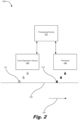
- Fig. 2 is a block diagram of a deposition module (200) within a web press for inhibiting media (150) deformation, according to an example of the principles described herein.
- the systems and methods of inhibition of deformations in the media (150) allow for dimensional expansion along the surface of the media (150) through application of the wetting agent (151) and/or a printing fluid (153), but ensures that deformations do not occur despite the application of the wetting agent (151) and/or a printing fluid (153).
- the deposition module (200) of Fig. 2 includes similar elements as described in connection with Fig. 1 herein, and description of those elements is provided in connection with Fig. 1 .
- the deposition module (200) also includes a printhead (152) that deposits printing fluid (153) such as an ink onto the media (150) after the fluid deposition device (100) has deposited the wetting agent (151) onto the media (150).
- the processing device (101) may control the deposition of the printing fluid (153) as well as the deposition of the wetting agent (151) onto the media (150) based on the print data supplied to the processing device (101).
- any number of printheads (152) may be included within the deposition module (200) to allow any number of colors to be printed to the media (150).
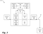
- Fig. 3 is a block diagram of a system (300) for inhibiting media (150) deformation, according to an example of the principles described herein.
- the system may be or include a web press.
- the system (300) may include an unwinding device (301).
- the unwinding device (301) includes a spool of print media web, and may be spooled out to through a printing device (350) for deposition of the wetting agent (151) and printing fluid (153).
- the system (300) may also include a rewinding device (304).
- the rewinding device (304) is used to collect the printed-on web (150) onto a spool much like the web (150) existed as it sat on the unwinding device (301) before the web (150) was unspooled from the unwinding device (301).
- the system (300) may also include a number of finishing devices (305).
- the finishing device (305) may be located between the printing device and the rewinding device (304), or may be in place of the rewinding device (304) to perform at least one post-printing operation on the media (150).
- Post-printing operations performed by the finishing device (305) may include, for example, cutting, folding, collating, packaging, other finishing processes, or combinations thereof.
- the printing device (350) of the system (300) of Fig. 3 may include the processing device (101) and printhead (152) described herein. Further, the printing device (350) may include a first fluid deposition device (100-1) and a second fluid deposition device (100-2) located on opposite sides of the media (150). In some examples, the wetting agent (151) may be deposited on both sides of the media (150) by activation of the first fluid deposition device (100-1) and the second fluid deposition device (100-2) positioned in this manner relative to the media (150).
- the wetting agent (151) may be printed on both sides of the media (150) along with the printed content in order to inhibit the deformation of the media (150) as ink is applied to both sides. Further, in examples, where one side is to be printed heavily with content including text and/or images with little or no content printed on the other side, the wetting agent (151) may be applied to the side with little or no content printed thereon. In these examples, the wetting agent (151) may be applied to portions of one or both sides of the media (150) to inhibit differential expansion of the media (150) that leads to the types of deformation of the media (150) described herein.
- the differential expansion caused by the application of a printing fluid causes the media (150) to become deformed.
- the application of the wetting agent (151) as described herein inhibits this deformation by counteracting the effects of the differential expansion caused by the application of a printing fluid.
- the printing device (350) may also include a number of modules used in the implementation of wetting agent (151) application to the media (150) to inhibit deformations in the media (150).
- the various modules within the printing device (350) include executable program code that may be executed separately.
- the various modules may be stored as separate computer program products.
- the various modules within the printing device (350) may be combined within a number of computer program products; each computer program product comprising a number of the modules.
- the printing device (350) may include a deposition mode selection module (302) to, when executed by the processing device (101), allow for the automatic selection and/or user-selection of a mode of wetting agent (151) deposition.
- the modes of deposition of the wetting agent (151) include, for example, application of the wetting agent (151) under printed portions of the media (150), application of the wetting agent (151) in portions of the media (150) where the printed portions are do not exist, flood coating of the wetting agent (151), application of the wetting agent (151) under printed portions of the media (150) using blooming function, application of the wetting agent (151) under printed portions of the media (150) using a blooming function, varying the amounts of wetting agent (151) applied to the media (150) in any of the above examples, other wetting agent (151) deposition modes, and combinations thereof.
- the application of the wetting agent (151) to the media (150) may not be beneficial to inhibiting deformation of the media (150).
- the wetting agent (151) is not applied to the media (150) before printing.
- Figs. 4 and 5 depict a scenario where no wetting agent (151) is applied to the media (150).
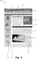
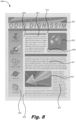
- Fig. 4 is a diagram of a document (400) for application of the wetting agent (151), according to an example of the principles described herein
- Fig. 5 is a diagram of a portion of the document (400) of Fig. 4 , according to an example of the principles described herein.
- the document (400) of Figs. 4 and 5 as well as documents depicted in Figs.
- document (400) of Figs. 4 and 5 may include text portions (401) where text is included in the document (400), and graphics portions (402) where graphics are included in the document (400). Further, the document (400) may include a number of spaces (403) between the text portions (401) and graphics portions (402).
- FIG. 4 In the case of Figs. 4 and 5 , no wetting agent (151) has been applied to the dummy text document (400).
- Section 450 of Fig. 4 is depicted in Fig. 5 and includes details of the both text portions (401) and graphics portions (402).
- Figs. 4 and 5 may be used by way of comparison relative to Figs. 6 through 11 as to how the wetting agent (151) is applied to the dummy text document (400).
- the different types of wetting agent (151) deposition that are available as selectable modes by the deposition mode selection module (302) will now be described in more detail.
- a first mode may include depositing the wetting agent (151) under the printed portions of the document (400) as depicted in Figs. 6 and 7 .
- Fig. 6 is a diagram of the document (400) of Fig. 4 including the wetting agent (151) applied under printed portions (401, 402) of the document (400), according to an example of the principles described herein.
- Fig. 7 is a diagram of a portion (650) of the document (400) of Fig. 6 , according to an example of the principles described herein.
- the wetting agent (151) may be deposited by the processing device (101) executing the deposition mode selection module (302) and controlling the first fluid deposition device (100-1) and/or the second fluid deposition device (100-2) to deposit the wetting agent (151) onto the media (150).
- the wetting agent (151) may be deposited based on print data supplied to the processing device (101) and controlling the digitally addressable fluid deposition devices (100-1, 100-2) to deposit the wetting agent (151) onto portions where the text portions (401) and the graphics portions (402) of the document (400) are to be printed by the printhead (152). As depicted in Fig. 7 , the wetting agent (151) is depicted as a being deposited below the text portion (401) and a graphics portion (402) as indicated by the silhouette around the text of the text portion (401) and the graphics of the graphics portion (402).
- the wetting agent (151) may be deposited directly underneath the text portion (401) and a graphics portion (402), or a blooming function may be executed by the processing device (101) to expand the area of deposition of the wetting agent (151) around where the printing fluid (153) is to be deposited by the printhead (152).
- the processing device (101) is able to expand the area under the text portions (401) and a graphics portions (402) of the document so that any errors in the deposition of the printing fluid (153) will not result in the printing fluid (153) being deposited on a portion of the document (140) that is not covered by the wetting agent (151). It is noted that the wetting agent (151) in Figs.
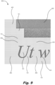
- a second mode of wetting agent (151) deposition may include depositing the wetting agent (151) in a flood coat where the wetting agent (151) is deposited on the whole frame of the media (150).
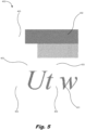
- Fig. 8 is a diagram of the document (400) of Fig. 4 including a wetting agent (151) applied in a flooded manner across the document (400), according to an example of the principles described herein.
- Fig. 9 is a diagram of a portion of the document (400) of Fig. 8 , according to an example of the principles described herein. As depicted in Figs. 8 and 9 as compared to, for example, Figs.
- the wetting agent (151) is deposited under the text portions (401) and graphics portions (402) as well as in the spaces (403) between the text portions (401) and graphics portions (402).
- wetting agent (151) By depositing wetting agent (151) throughout the entirety of the frame of the media (150) in which the text portions (401) and graphics portions (402) are to be printed, deformations may not be formed since the entirety of the frame of the media (150) has been relaxed by the wetting agent (151) and will dry at approximately the same rate such that the deformations will not form.
- a variable flood coat of the wetting agent (151) may be applied to the media (150).
- a configurable and relatively different amount of wetting agent (151) may be deposited under the text portions (401), the graphics portions (402), and the spaces (403) between the text portions (401) and graphics portions (402).
- a least amount of wetting agent (151) may be deposited at areas of the media (150) where the graphics portions (402) are to be printed
- a relatively greater amount of wetting agent (151) may be deposited at areas of the media (150) where the text portions (401) are to printed
- a relatively greatest amount of wetting agent (151) may be deposited at areas of the media (150) where the spaces (403) exists.
- the amount of wetting agent (151) applied in the spaces (403) may be considered a baseline 100%.
- the amount of wetting agent (151) applied under the text portions (401) may be less than 100% of the amount of wetting agent (151) applied at the spaces (403) but greater than the percentage of wetting agent (151) applied under the graphics portions (402), and the amount of wetting agent (151) applied under the graphics portions (402) may be less than the percentage of wetting agent (151) deposited under the text portions (401).
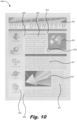
- a third mode of wetting agent (151) deposition may include depositing the wetting agent (151) as a background coating where the wetting agent (151) is applied to background areas where text and graphics are not printed on the media (150).
- the wetting agent (151) is deposited on the spaces (403) between the text portions (401) and graphics portions (402).
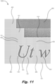
- Fig. 10 is a diagram of the document (400) of Fig. 4 including a wetting agent (151) applied to background portions (403) of the document (403), according to an example of the principles described herein.
- Fig. 11 is a diagram of a portion of the document (400) of Fig. 10 , according to an example of the principles described herein.
- the processor (101) may execute an inverted blooming function.
- the processing device (101) when using a blooming function, the processing device (101) is able to expand the area under the text portions (401) and a graphics portions (402) of the document (400).
- the inverted blooming function takes the results of the blooming function, inverts the data, and produces wetting agent (151) deposition data based on the inverted data.
- the spaces (403) between the text portions (401) and graphics portions (402) (i.e., the background) within the document (400) may be coated with the wetting agent (151).
- the wetting agent (151) is depicted as a being deposited around the text portion (401) and a graphics portion (402) as indicated by the silhouette (1101) around the text of the text portion (401) and the graphics of the graphics portion (402).
- the silhouette (1101) is the opposite of the silhouette described above in connection with Fig. 7 in that the silhouette depicted in Fig. 7 indicates where wetting agent (151) is deposited next to the text portions (401) and the graphics portions (402), whereas the silhouette (1101) around the text portions (401) and the graphics portions (402) depicted in Fig. 11 indicate where wetting agent (151) is not deposited due to the application of the inverted blooming function.
- Figs. 10 and 11 leverages the blooming function by inverting bloomed data to create a depleted background fill so that the text portions (401) and graphics portions (402) are not likely to encounter the wetting agent (151) and create an unwanted image effect when printing occurs.
- the print data may be pre-warped, and a depletion function may be executed by the processing device (101).
- Other methods of obtaining data defining the spaces (403) between the text portions (401) and graphics portions (402) i.e., background data
- the pre-calculated color planes used to instruct the printhead (152) to deposit printing fluid (153) onto the media (150) may be leveraged to re-map the print data to provide wetting agent deposition planes for use by the fluid deposition devices (100, 100-1, 100-2) within the printing device (350).
- Use of existing color planes in this way significantly reduces processing time of the printing device (350) and allows the printing device (350) to implement the systems and methods described herein with any set of print data provided to the printing device (350).
- remapping the print data may include the backend of the print pipeline of the printing device (350) to have information as to what mode of wetting agent (151) deposition is selected.
- the printing device (350) may remap the data to output data in a masking or mapping process to choose the amount of wetting agent (151) such as a number of drops deposited by the fluid deposition devices (100, 100-1, 100-2).
- Incoming print data may be mapped to a printed output drop.
- the mapping may be changed so that the print data may be warped to no output, no print data to a printed output, or combinations thereof. This warping may be performed by software, or in hardware such as in a field-programmable gate array (FPGA), or combinations thereof.
- FPGA field-programmable gate array
- of an efficient implementation is through the use of a look-up table (LUT).
- certain areas or portions of the media (150) may not be selected for deposition of the wetting agent (151) or printing fluid (153). These areas or portions may include, for example, margins of the document. Not depositing wetting agent (151) or printing fluid (153) in these areas or portions ensure that the wetting agent (151) is not wasted on these areas that are not of consequence in printing the document.
- the printing device may also include a wetting agent selection module (303) and a graphic user interface (GUI) (306) along with the deposition mode selection module (302).
- the processing device (101) may execute the wetting agent selection module (303) to present on the GUI (306) a number of user-selectable options such as the type of media (150) being printed on, a desired mode of wetting agent (151) deposition, and a desired type of wetting agent.
- the user may make a selection, and the printing device (350) may deposit the wetting agent (151) and printing fluid (153) onto the media (150) according to the user's selections.
- the user may select a type of wetting agent to apply to the media as provided by the wetting agent selection module (303), and a mode of deposition as provided by the deposition mode selection module (302).
- selection of the deposition mode and the wetting agent may be performed automatically by the printing device (350).
- the user may be prompted to indicate via the GUI (306) the type of media (150) the print data is to be printed on.
- the printing device (350) may then select the type of wetting agent (151) to use by executing the wetting agent selection module (303) to automatically select a type of wetting agent (151) to deposit on the media (150) based on the type of media (150) identified by the user.
- the printing device (350) may also select the mode of deposition of the wetting agent (151) on the media (150) based on the type of media (150) identified by the user.
- the printing device (350) may also consider the print data defining the text and graphics to be printed on the media (150) in determining which mode of deposition of the wetting agent to use as the print data defines how much the printing fluid (153) deposited by the printhead (152) will effect the potential for deformation of the media (150).
- the type of wetting agent (151) may be user-selectable from the GUI (306) at the inception of a print job.
- information encoded by a DFE may be automatically selected as part of print job characteristic control bits that are passed from the DFE to the rest of the printing system. This may give the customer a user-selectable option to combat media issues on types of print jobs that are known to be prone to media deformation.
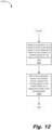
- Fig. 12 is a flowchart showing a method (1200) of inhibiting media (150) deformation, according to an example of the principles described herein.
- the method (1200) may include, determining (block 1201) positions on a media (150) at which a wetting agent (151) is to be deposited based on the location of content printed on the media (150) as defined by print data.
- the positions as to where the wetting agent (151) may be deposited on the media (150) may be based on the type of media (150) being printed on, the mode of wetting agent (151) deposition, and the type of wetting agent (151) selected for deposition, as well as the location of the content printed on the media (150).
- the method may also include, with a fluid deposition device (100, 100-1, 100-2) of a printing device (350), depositing (block 1202) the wetting agent (151) on the media (150) based on a deposition mode of the wetting agent (151).
- the modes of deposition of the wetting agent (151) include, for example, application of the wetting agent (151) under printed portions of the media (150), application of the wetting agent (151) in portions of the media (150) where the printed portions are do not exist, flood coating of the wetting agent (151), application of the wetting agent (151) under printed portions of the media (150) using blooming function, application of the wetting agent (151) under printed portions of the media (150) using a blooming function, varying the amounts of wetting agent (151) applied to the media (150) in any of the above examples, other wetting agent (151) deposition modes, and combinations thereof.
- Fig. 13 is a flowchart showing a method (1300) of inhibiting media deformation, according to an example of the principles described herein.
- the method (1300) of fig. 13 may begin by determining (block 1301) whether the media is susceptible to media deformation.
- the printing device (350) may determine (block 1303) positions on the media (150) at which the wetting agent (151) is to be deposited based on the location of content printed on the media (150) as defined by print data.
- the printing device (350) may select (block 1302) the deposition mode of the wetting agent (151) based on the determination as to whether the media (150) is susceptible to media deformation.
- the method (1300) may then proceed to block 1303.
- the wetting agent (151) may be deposited (block 1304) on the media (150) based on a deposition mode of the wetting agent (151).
- the computer usable program code may be provided to a processor of a general purpose computer, special purpose computer, or other programmable data processing apparatus to produce a machine, such that the computer usable program code, when executed via, for example, the processing device (101) of the printing device (350) or other programmable data processing apparatus, implement the functions or acts specified in the flowchart and/or block diagram block or blocks.
- the computer usable program code may be embodied within a computer readable storage medium; the computer readable storage medium being part of the computer program product.
- the computer readable storage medium is a non-transitory computer readable medium.
- the specification and figures describe a deposition module within a web press for inhibiting media deformation.
- the deposition module may include a fluid deposition device located on a side of a media, and a processing device to control the fluid deposition device to selectively apply a wetting agent to the media.
- the deposition of the wetting agent may be based on the location of content printed on the media as defined by print data.
- the systems and methods described herein provide for the addition of moisture that assists in reducing, eliminating, or inhibiting differential expansion of the media that may otherwise lead to deformation of the media.
- the systems and methods described herein do not use additional color plane data from the DFE or additional print bars on the press which may detrimentally impact the speed at which a user may run using existing hardware.
Landscapes
- Ink Jet (AREA)
- Accessory Devices And Overall Control Thereof (AREA)
Description
- An inkjet web press is a high-speed, digital, industrial printing device that prints on a continuous media web at speeds of hundreds of feet per minute. A roll of media such as a paper on an unwinding device supplies the press with a web which is conveyed through the press along a media path. Stationary printheads along the media path may eject droplets of printing fluid onto the web to form images. The web may be conveyed through a drying area and out of the press through rollers to be rewound on a rewinding device.
- The accompanying drawings illustrate various examples of the principles described herein and are part of the specification. The illustrated examples are given merely for illustration, and do not limit the scope of the claims.
-
Fig. 1 is a block diagram of a deposition module within a web press for inhibiting media deformation, according to an example of the principles described herein. -
Fig. 2 is a block diagram of a deposition module within a web press for inhibiting media deformation, according to an example of the principles described herein. -
Fig. 3 is a block diagram of a system for inhibiting media deformation, according to an example of the principles described herein. -
Fig. 4 is a diagram of a document for application of a wetting agent, according to an example of the principles described herein. -
Fig. 5 is a diagram of a portion of the document ofFig. 4 , according to an example of the principles described herein. -
Fig. 6 is a diagram of the document ofFig. 4 including a wetting agent applied under printed portions of the document, according to an example of the principles described herein. -
Fig. 7 is a diagram of a portion of the document ofFig. 6 , according to an example of the principles described herein. -
Fig. 8 is a diagram of the document ofFig. 4 including a wetting agent applied in a flooded manner across the document, according to an example of the principles described herein. -
Fig. 9 is a diagram of a portion of the document ofFig. 8 , according to an example of the principles described herein. -
Fig. 10 is a diagram of the document ofFig. 4 including a wetting agent applied to background portions of the document, according to an example of the principles described herein. -
Fig. 11 is a diagram of a portion of the document ofFig. 10 , according to an example of the principles described herein. -
Fig. 12 is a flowchart showing a method of inhibiting media deformation, according to an example of the principles described herein. -
Fig. 13 is a flowchart showing a method of inhibiting media deformation, according to an example of the principles described herein. - Throughout the drawings, identical reference numbers designate similar, but not necessarily identical, elements. The figures are not necessarily to scale, and the size of some parts may be exaggerated to more clearly illustrate the example shown. Moreover, the drawings provide examples and/or implementations consistent with the description; however, the description is not limited to the examples and/or implementations provided in the drawings.
- Print fluid used in printing may include a significant amount of water that can saturate the web or other media that is being printed on. As this water is applied to the media, hydrogen bonds within the paper may be disassociated, and the fibers within the media may grow. Because printing is performed selectively where not all portions of the media is printed on and subjected to this fiber growth, a change in the stress strain profile of the paper occurs, and deformations within the media may form due to differential expansion along the length and width of the media. The moisture content of the web and tension along the media path within the press, among other factors, may cause the web to become deformed and produce media defects. Forms of deformation that may occur when the media is printed on may include curling, wrinkling, creasing, and other types of deformations within the media. Further, when there is significant variation across a printed media, or variation between the printed portions on the front and back of the media, it is possible that a variety of these deformations may occur. These deformations are due, at least in part, to different amounts of moisture content within the printing fluids such as inks or other fluids deposited on the media that causes the differential expansion along the length and width of the media.
- Further, as the media subsequently dries, the drying may additionally affect the level of deformations within the media. For example, a first print job may include a book in which one side of a page is a line drawing or light text, and the backside is a solid area fill. In another example, a second print job may include a top liner for a corrugate product in which there is a box being printed with heavy printed content on the sides of the box, and relatively little to no content on the bottom of the box, which would form a 'ring' shape of heavy content. In the first print job, to balance the heavy content, it may be desirable to add moisture on the opposite side of the heavy content to inhibit curl. In the second print job, it may be desirable to add moisture to the same side to inhibit media puckering and wrinkling. In both examples, the technique of adding moisture assists in reducing or eliminating differential expansion of the media. Document
US 2014/292843 discloses such a printing apparatus which deposits a variable amount of treatment fluid in addition to the printed image data. - The invention is defined by the claims. Examples described herein provide a deposition module within a web press for inhibiting media deformation. The deposition module may include a fluid deposition device located on a side of a media, and a processing device to control the fluid deposition device to selectively apply a wetting agent to the media. The deposition of the wetting agent may be based on the location of content printed on the media as defined by print data.
- The fluid deposition device includes two fluid deposition devices. The fluid deposition devices are located on opposite sides of the media. The processing device controls the fluid deposition device to selectively apply the wetting agent to portions of the media where the content is not printed on the media. The processing device controls the fluid deposition device to selectively apply the wetting agent to portions of the media where the content is not printed on the media and where the content is printed on the media. The amount of wetting agent deposited on the media where the content is not printed is different from the amount of the wetting agent where the content is printed. The fluid deposition device may be a thermal inkjet printhead or a piezoelectric printhead. The processing device controls the fluid deposition device to selectively apply the wetting agent to portions of the media based on blooming where the content is and is not printed as defined by the print data.
- Examples described herein provide a system for inhibiting media deformation. Inhibiting deformation in the media includes reducing to any level the curling, wrinkling, creasing, and other types of deformations in the media up to and including preventing or eliminating such deformations. The examples described herein allows for the management of the deformation in a way that allows for dimensional expansion in the media, while managing the deformations.
- The system may include a web press. The web press may include an inkjet printhead and a fluid deposition device located on a side of a media to deposit a wetting agent onto a media. The system may also include a processing device to control the fluid deposition device to selectively apply the wetting agent to the media based on the location of content printed on the media as defined by print data. The processing device controls the fluid deposition device to selectively apply the wetting agent to portions of the media where the content is not printed on the media and where the content is printed on the media. The amount of wetting agent deposited on the media where the content is not printed is different from the amount of the wetting agent where the content is printed. The processing device controls the fluid deposition device to apply the wetting agent to a whole frame as defined by the print data. The processing device controls the fluid deposition device to selectively apply the wetting agent to portions of the media where the content is not printed on the media and where the content is printed on the media.
- The amount of the wetting agent dispensed by the fluid deposition device is variable. The system may include a deposition mode selection module to, when executed by the processing device, select a wetting agent deposition mode based on print data. The system may include a wetting agent selection module to select a wetting agent for deposition.
- Examples described herein provide a method of inhibiting media deformation. The method may include determining positions on a media at which a wetting agent is to be deposited based on the location of content printed on the media as defined by print data, and, with a fluid deposition device of a printing device, depositing the wetting agent on the media based on a deposition mode of the wetting agent. The method may include determining from the intended printed content whether the media is susceptible to media deformation, and selecting the deposition mode of the wetting agent based on the determination as to whether the media is susceptible to media deformation.
- Turning now to the figures,
Fig. 1 is a block diagram of a deposition module (110) within a web press for inhibiting media deformation, according to an example of the principles described herein. The deposition module (110) may be a device capable of depositing fluid (151) onto a media (150) such as, for example, a printhead such as those printheads used to print printing fluid onto the media (150). In this example, the deposition module (110) may be located alongside a number of ink printheads that are used to print images and text onto the media (150). - The deposition module (110) may include at least one fluid deposition device (100) that is the device within the deposition module (150) that is activated to deposit fluid (151) onto the media (150). Examples of fluid deposition device (100) include thermal ejection devices, piezoelectrical ejection devices, and other types of fluid ejection devices. As the media (150) travels along a print path in the direction of
arrow 140, the fluid deposition device (100) deposits the fluid (151) onto the media (150) as instructed by the processing device (101). - The fluid (151) deposited by the fluid deposition device (100) may include any colorless fluid that may inhibit, reduce, or prevent deformations when ink is printed onto the media (150). In one example, the fluid (151) may be a precursor that conditions the medium surface prior to application of one or more colorants to the recording medium surface of the media. Thus, as defined herein, the term "wetting agent," "bonding agent," "fixing fluid," "fixer," or similar terms as used in the present specification and in the appended claims is meant to be understood broadly as any fluid that chemically, electrically, or otherwise physically inhibits, reduces, or prevents deformations when ink is printed onto the media (150).
- In an example, the wetting agent (151) may include a large proportion of water to assist in the ejection of the wetting agent (151) from the fluid deposition device (100). For example, the water in the wetting agent (151) may assist in a thermal inkjet process in examples where the fluid deposition device (100) is a thermal inkjet printhead. The water component within the wetting agent (151) relaxes the media (150) to inhibit the curling of the media (150). The wetting agent (151) may also include chemical substances used to keep the fluid deposition device (100) healthy as to its ability to eject the wetting agent (151), and may also include a salt to crash the pigments deposited by the printhead (152) during printing.
- The deposition module (110) also includes a processing device (101) to control the fluid deposition device (100) to selectively apply a wetting agent (151) to the media. The processing device (101) may be any device that provides print data to the fluid deposition device (100) that defines where ink is to be printed to the media (150). The processing device (101) may use the print data to allow the fluid deposition device (100) to print the wetting agent (151) at portions of the media (150) where ink is to be printed, at portions of the media (150) where the ink is not to be printed such as background portions, throughout an entirety of the media (150), at varying portions of the media (150), at varying amounts or gradients of the wetting agent (151), and combinations thereof. In this manner, the deposition of the wetting agent may be based on the location of content printed on the media (150) as defined by the print data supplied to the processing device (101).
- The deposition module (110) allows for the inhibition, reduction, or prevention of deformation of the media by selectively printing or not printing the wetting agent (151) under the printed content and not at other locations, in the background and not under the printed content, as a flood coat, and with the ability to set different levels of fixer being deposited under content and in the background. Further, as described herein, by leveraging the print data by performing additional processing on the print data in the processing device, the deposition module (110) does not require the use of additional color plane data from a digital front end (DFE) or additional print bars on the web press in which the deposition module (110) is included. This, in turn, allows an operator to execute print jobs that maximize the resources (such as memory, bandwidth or processing speed) of the processing module. If a separate plane was used, additional hardware may be used to maintain the performance of the printing device, or the operator may be forced to slow down the printing process.
-
Fig. 2 is a block diagram of a deposition module (200) within a web press for inhibiting media (150) deformation, according to an example of the principles described herein. The systems and methods of inhibition of deformations in the media (150) allow for dimensional expansion along the surface of the media (150) through application of the wetting agent (151) and/or a printing fluid (153), but ensures that deformations do not occur despite the application of the wetting agent (151) and/or a printing fluid (153). The deposition module (200) ofFig. 2 includes similar elements as described in connection withFig. 1 herein, and description of those elements is provided in connection withFig. 1 . The deposition module (200) also includes a printhead (152) that deposits printing fluid (153) such as an ink onto the media (150) after the fluid deposition device (100) has deposited the wetting agent (151) onto the media (150). The processing device (101) may control the deposition of the printing fluid (153) as well as the deposition of the wetting agent (151) onto the media (150) based on the print data supplied to the processing device (101). Although one printhead (152) is depicted inFig. 2 , any number of printheads (152) may be included within the deposition module (200) to allow any number of colors to be printed to the media (150). -
Fig. 3 is a block diagram of a system (300) for inhibiting media (150) deformation, according to an example of the principles described herein. In one example, the system may be or include a web press. The system (300) may include an unwinding device (301). The unwinding device (301) includes a spool of print media web, and may be spooled out to through a printing device (350) for deposition of the wetting agent (151) and printing fluid (153). The system (300) may also include a rewinding device (304). The rewinding device (304) is used to collect the printed-on web (150) onto a spool much like the web (150) existed as it sat on the unwinding device (301) before the web (150) was unspooled from the unwinding device (301). Further, the system (300) may also include a number of finishing devices (305). The finishing device (305) may be located between the printing device and the rewinding device (304), or may be in place of the rewinding device (304) to perform at least one post-printing operation on the media (150). Post-printing operations performed by the finishing device (305) may include, for example, cutting, folding, collating, packaging, other finishing processes, or combinations thereof. - The printing device (350) of the system (300) of
Fig. 3 may include the processing device (101) and printhead (152) described herein. Further, the printing device (350) may include a first fluid deposition device (100-1) and a second fluid deposition device (100-2) located on opposite sides of the media (150). In some examples, the wetting agent (151) may be deposited on both sides of the media (150) by activation of the first fluid deposition device (100-1) and the second fluid deposition device (100-2) positioned in this manner relative to the media (150). For example, if the media (150) is being printed in duplex where content is printed on both sides of the media (150), the wetting agent (151) may be printed on both sides of the media (150) along with the printed content in order to inhibit the deformation of the media (150) as ink is applied to both sides. Further, in examples, where one side is to be printed heavily with content including text and/or images with little or no content printed on the other side, the wetting agent (151) may be applied to the side with little or no content printed thereon. In these examples, the wetting agent (151) may be applied to portions of one or both sides of the media (150) to inhibit differential expansion of the media (150) that leads to the types of deformation of the media (150) described herein. As the media (150) dries, the differential expansion caused by the application of a printing fluid causes the media (150) to become deformed. The application of the wetting agent (151) as described herein inhibits this deformation by counteracting the effects of the differential expansion caused by the application of a printing fluid. - The printing device (350) may also include a number of modules used in the implementation of wetting agent (151) application to the media (150) to inhibit deformations in the media (150). The various modules within the printing device (350) include executable program code that may be executed separately. In this example, the various modules may be stored as separate computer program products. In another example, the various modules within the printing device (350) may be combined within a number of computer program products; each computer program product comprising a number of the modules.
- The printing device (350) may include a deposition mode selection module (302) to, when executed by the processing device (101), allow for the automatic selection and/or user-selection of a mode of wetting agent (151) deposition. The modes of deposition of the wetting agent (151) include, for example, application of the wetting agent (151) under printed portions of the media (150), application of the wetting agent (151) in portions of the media (150) where the printed portions are do not exist, flood coating of the wetting agent (151), application of the wetting agent (151) under printed portions of the media (150) using blooming function, application of the wetting agent (151) under printed portions of the media (150) using a blooming function, varying the amounts of wetting agent (151) applied to the media (150) in any of the above examples, other wetting agent (151) deposition modes, and combinations thereof.
- In some examples, the application of the wetting agent (151) to the media (150) may not be beneficial to inhibiting deformation of the media (150). In this example, the wetting agent (151) is not applied to the media (150) before printing.
Figs. 4 and5 depict a scenario where no wetting agent (151) is applied to the media (150). Specifically,Fig. 4 is a diagram of a document (400) for application of the wetting agent (151), according to an example of the principles described herein, andFig. 5 is a diagram of a portion of the document (400) ofFig. 4 , according to an example of the principles described herein. The document (400) ofFigs. 4 and5 , as well as documents depicted inFigs. 6 through 11 , are dummy text and graphics documents that demonstrate the visual form of a document without relying on meaningful content (i.e., greeking) by replacing actual content with placeholder text and graphics. Thus, document (400) ofFigs. 4 and5 , as well as the documents depicted inFigs. 6 through 11 , may include text portions (401) where text is included in the document (400), and graphics portions (402) where graphics are included in the document (400). Further, the document (400) may include a number of spaces (403) between the text portions (401) and graphics portions (402). - In the case of
Figs. 4 and5 , no wetting agent (151) has been applied to the dummy text document (400).Section 450 ofFig. 4 is depicted inFig. 5 and includes details of the both text portions (401) and graphics portions (402).Figs. 4 and5 may be used by way of comparison relative toFigs. 6 through 11 as to how the wetting agent (151) is applied to the dummy text document (400). The different types of wetting agent (151) deposition that are available as selectable modes by the deposition mode selection module (302) will now be described in more detail. - A first mode may include depositing the wetting agent (151) under the printed portions of the document (400) as depicted in
Figs. 6 and7 .Fig. 6 is a diagram of the document (400) ofFig. 4 including the wetting agent (151) applied under printed portions (401, 402) of the document (400), according to an example of the principles described herein.Fig. 7 is a diagram of a portion (650) of the document (400) ofFig. 6 , according to an example of the principles described herein. The wetting agent (151) may be deposited by the processing device (101) executing the deposition mode selection module (302) and controlling the first fluid deposition device (100-1) and/or the second fluid deposition device (100-2) to deposit the wetting agent (151) onto the media (150). - The wetting agent (151) may be deposited based on print data supplied to the processing device (101) and controlling the digitally addressable fluid deposition devices (100-1, 100-2) to deposit the wetting agent (151) onto portions where the text portions (401) and the graphics portions (402) of the document (400) are to be printed by the printhead (152). As depicted in
Fig. 7 , the wetting agent (151) is depicted as a being deposited below the text portion (401) and a graphics portion (402) as indicated by the silhouette around the text of the text portion (401) and the graphics of the graphics portion (402). - In the example of
Figs, 6 and7 , the wetting agent (151) may be deposited directly underneath the text portion (401) and a graphics portion (402), or a blooming function may be executed by the processing device (101) to expand the area of deposition of the wetting agent (151) around where the printing fluid (153) is to be deposited by the printhead (152). When using the blooming function, the processing device (101) is able to expand the area under the text portions (401) and a graphics portions (402) of the document so that any errors in the deposition of the printing fluid (153) will not result in the printing fluid (153) being deposited on a portion of the document (140) that is not covered by the wetting agent (151). It is noted that the wetting agent (151) inFigs. 6 and7 is not deposited in the spaces (403) between the text portions (401) and graphics portions (402). By not depositing the wetting agent (151) in the spaces (403), the wetting agent (151) is not overconsumed or overused, resulting in less expensive print job for the user. - A second mode of wetting agent (151) deposition may include depositing the wetting agent (151) in a flood coat where the wetting agent (151) is deposited on the whole frame of the media (150).
Fig. 8 is a diagram of the document (400) ofFig. 4 including a wetting agent (151) applied in a flooded manner across the document (400), according to an example of the principles described herein. Further,Fig. 9 is a diagram of a portion of the document (400) ofFig. 8 , according to an example of the principles described herein. As depicted inFigs. 8 and9 as compared to, for example,Figs. 4 and5 , the wetting agent (151) is deposited under the text portions (401) and graphics portions (402) as well as in the spaces (403) between the text portions (401) and graphics portions (402). By depositing wetting agent (151) throughout the entirety of the frame of the media (150) in which the text portions (401) and graphics portions (402) are to be printed, deformations may not be formed since the entirety of the frame of the media (150) has been relaxed by the wetting agent (151) and will dry at approximately the same rate such that the deformations will not form. - As an example of flood coating of the wetting agent (151), a variable flood coat of the wetting agent (151) may be applied to the media (150). In this example, a configurable and relatively different amount of wetting agent (151) may be deposited under the text portions (401), the graphics portions (402), and the spaces (403) between the text portions (401) and graphics portions (402). For example, a least amount of wetting agent (151) may be deposited at areas of the media (150) where the graphics portions (402) are to be printed, a relatively greater amount of wetting agent (151) may be deposited at areas of the media (150) where the text portions (401) are to printed, and a relatively greatest amount of wetting agent (151) may be deposited at areas of the media (150) where the spaces (403) exists.
- In this example, the amount of wetting agent (151) applied in the spaces (403) may be considered a
baseline 100%. The amount of wetting agent (151) applied under the text portions (401) may be less than 100% of the amount of wetting agent (151) applied at the spaces (403) but greater than the percentage of wetting agent (151) applied under the graphics portions (402), and the amount of wetting agent (151) applied under the graphics portions (402) may be less than the percentage of wetting agent (151) deposited under the text portions (401). By varying the amount of wetting agent (151) applied in a flooded manner along the entirety of the media (150) provides flexibility to mitigate the cost to the user for deposition of the wetting agent (151) in the printed document while providing flexibility to choose a solution that inhibits deformation in the media (150) most effectively. - A third mode of wetting agent (151) deposition may include depositing the wetting agent (151) as a background coating where the wetting agent (151) is applied to background areas where text and graphics are not printed on the media (150). In other words, in the example of
Figs. 10 and11 , the wetting agent (151) is deposited on the spaces (403) between the text portions (401) and graphics portions (402).Fig. 10 is a diagram of the document (400) ofFig. 4 including a wetting agent (151) applied to background portions (403) of the document (403), according to an example of the principles described herein.Fig. 11 is a diagram of a portion of the document (400) ofFig. 10 , according to an example of the principles described herein. In order to derive data defining where the wetting agent (151) is to be deposited in the example ofFigs. 10 and11 , in one example, the processor (101) may execute an inverted blooming function. - As described herein, when using a blooming function, the processing device (101) is able to expand the area under the text portions (401) and a graphics portions (402) of the document (400). The inverted blooming function takes the results of the blooming function, inverts the data, and produces wetting agent (151) deposition data based on the inverted data. In this manner, the spaces (403) between the text portions (401) and graphics portions (402) (i.e., the background) within the document (400) may be coated with the wetting agent (151). As depicted in
Fig. 11 , the wetting agent (151) is depicted as a being deposited around the text portion (401) and a graphics portion (402) as indicated by the silhouette (1101) around the text of the text portion (401) and the graphics of the graphics portion (402). The silhouette (1101) is the opposite of the silhouette described above in connection withFig. 7 in that the silhouette depicted inFig. 7 indicates where wetting agent (151) is deposited next to the text portions (401) and the graphics portions (402), whereas the silhouette (1101) around the text portions (401) and the graphics portions (402) depicted inFig. 11 indicate where wetting agent (151) is not deposited due to the application of the inverted blooming function. - The example of
Figs. 10 and11 leverages the blooming function by inverting bloomed data to create a depleted background fill so that the text portions (401) and graphics portions (402) are not likely to encounter the wetting agent (151) and create an unwanted image effect when printing occurs. In one example, the instead of executing an inverted blooming function to obtain the background fill as depicted inFigs. 10 and11 , the print data may be pre-warped, and a depletion function may be executed by the processing device (101). Other methods of obtaining data defining the spaces (403) between the text portions (401) and graphics portions (402) (i.e., background data) may be used. - Use of the modes of wetting agent (151) deposition described in connection with
Figs. 4 through 11 allows users to improve output quality of the printing device (350) by giving users the ability to select the quantity of the wetting agent (151) and the level of application such as flood coating, background coating, deposition under text, deposition under graphics, variable deposition, and combinations thereof, that best showcases their printed product while mitigating the printed defects caused by differential expansion of the media. - In the modes of wetting agent (151) deposition described in connection with
Figs. 4 through 11 , the pre-calculated color planes used to instruct the printhead (152) to deposit printing fluid (153) onto the media (150) may be leveraged to re-map the print data to provide wetting agent deposition planes for use by the fluid deposition devices (100, 100-1, 100-2) within the printing device (350). Use of existing color planes in this way significantly reduces processing time of the printing device (350) and allows the printing device (350) to implement the systems and methods described herein with any set of print data provided to the printing device (350). - In one example, remapping the print data may include the backend of the print pipeline of the printing device (350) to have information as to what mode of wetting agent (151) deposition is selected. The printing device (350) may remap the data to output data in a masking or mapping process to choose the amount of wetting agent (151) such as a number of drops deposited by the fluid deposition devices (100, 100-1, 100-2). Incoming print data may be mapped to a printed output drop. In this example, the mapping may be changed so that the print data may be warped to no output, no print data to a printed output, or combinations thereof. This warping may be performed by software, or in hardware such as in a field-programmable gate array (FPGA), or combinations thereof. In one example, of an efficient implementation is through the use of a look-up table (LUT).
- In one example, certain areas or portions of the media (150) may not be selected for deposition of the wetting agent (151) or printing fluid (153). These areas or portions may include, for example, margins of the document. Not depositing wetting agent (151) or printing fluid (153) in these areas or portions ensure that the wetting agent (151) is not wasted on these areas that are not of consequence in printing the document.
- Turning again to
Fig. 3 , the printing device may also include a wetting agent selection module (303) and a graphic user interface (GUI) (306) along with the deposition mode selection module (302). The processing device (101) may execute the wetting agent selection module (303) to present on the GUI (306) a number of user-selectable options such as the type of media (150) being printed on, a desired mode of wetting agent (151) deposition, and a desired type of wetting agent. In this example, the user may make a selection, and the printing device (350) may deposit the wetting agent (151) and printing fluid (153) onto the media (150) according to the user's selections. For example, the user may select a type of wetting agent to apply to the media as provided by the wetting agent selection module (303), and a mode of deposition as provided by the deposition mode selection module (302). - In an example, selection of the deposition mode and the wetting agent may be performed automatically by the printing device (350). In this example, the user may be prompted to indicate via the GUI (306) the type of media (150) the print data is to be printed on. The printing device (350) may then select the type of wetting agent (151) to use by executing the wetting agent selection module (303) to automatically select a type of wetting agent (151) to deposit on the media (150) based on the type of media (150) identified by the user. The printing device (350) may also select the mode of deposition of the wetting agent (151) on the media (150) based on the type of media (150) identified by the user. The printing device (350) may also consider the print data defining the text and graphics to be printed on the media (150) in determining which mode of deposition of the wetting agent to use as the print data defines how much the printing fluid (153) deposited by the printhead (152) will effect the potential for deformation of the media (150).
- In one example, the type of wetting agent (151) may be user-selectable from the GUI (306) at the inception of a print job. Further, in one example, information encoded by a DFE may be automatically selected as part of print job characteristic control bits that are passed from the DFE to the rest of the printing system. This may give the customer a user-selectable option to combat media issues on types of print jobs that are known to be prone to media deformation.
-
Fig. 12 is a flowchart showing a method (1200) of inhibiting media (150) deformation, according to an example of the principles described herein. The method (1200) may include, determining (block 1201) positions on a media (150) at which a wetting agent (151) is to be deposited based on the location of content printed on the media (150) as defined by print data. In an example, the positions as to where the wetting agent (151) may be deposited on the media (150) may be based on the type of media (150) being printed on, the mode of wetting agent (151) deposition, and the type of wetting agent (151) selected for deposition, as well as the location of the content printed on the media (150). - The method may also include, with a fluid deposition device (100, 100-1, 100-2) of a printing device (350), depositing (block 1202) the wetting agent (151) on the media (150) based on a deposition mode of the wetting agent (151). The modes of deposition of the wetting agent (151) include, for example, application of the wetting agent (151) under printed portions of the media (150), application of the wetting agent (151) in portions of the media (150) where the printed portions are do not exist, flood coating of the wetting agent (151), application of the wetting agent (151) under printed portions of the media (150) using blooming function, application of the wetting agent (151) under printed portions of the media (150) using a blooming function, varying the amounts of wetting agent (151) applied to the media (150) in any of the above examples, other wetting agent (151) deposition modes, and combinations thereof.
-
Fig. 13 is a flowchart showing a method (1300) of inhibiting media deformation, according to an example of the principles described herein. the method (1300) offig. 13 may begin by determining (block 1301) whether the media is susceptible to media deformation. In response to the determination that the media (150) is not susceptible to media deformation (block 1301, determination NO), the printing device (350) may determine (block 1303) positions on the media (150) at which the wetting agent (151) is to be deposited based on the location of content printed on the media (150) as defined by print data. - In response to the determination that the media (150) is susceptible to media deformation (
block 1301, determination YES), the printing device (350) may select (block 1302) the deposition mode of the wetting agent (151) based on the determination as to whether the media (150) is susceptible to media deformation. The method (1300) may then proceed to block 1303. With a fluid deposition device (100, 100-1, 100-2) of the printing device (350), the wetting agent (151) may be deposited (block 1304) on the media (150) based on a deposition mode of the wetting agent (151). - Aspects of the present system and method are described herein with reference to flowchart illustrations and/or block diagrams of methods, apparatus (systems) and computer program products according to examples of the principles described herein. Each block of the flowchart illustrations and block diagrams, and combinations of blocks in the flowchart illustrations and block diagrams, may be implemented by computer usable program code. The computer usable program code may be provided to a processor of a general purpose computer, special purpose computer, or other programmable data processing apparatus to produce a machine, such that the computer usable program code, when executed via, for example, the processing device (101) of the printing device (350) or other programmable data processing apparatus, implement the functions or acts specified in the flowchart and/or block diagram block or blocks. In one example, the computer usable program code may be embodied within a computer readable storage medium; the computer readable storage medium being part of the computer program product. In one example, the computer readable storage medium is a non-transitory computer readable medium.
- The specification and figures describe a deposition module within a web press for inhibiting media deformation. The deposition module may include a fluid deposition device located on a side of a media, and a processing device to control the fluid deposition device to selectively apply a wetting agent to the media. The deposition of the wetting agent may be based on the location of content printed on the media as defined by print data.
- The systems and methods described herein provide for the addition of moisture that assists in reducing, eliminating, or inhibiting differential expansion of the media that may otherwise lead to deformation of the media. The systems and methods described herein do not use additional color plane data from the DFE or additional print bars on the press which may detrimentally impact the speed at which a user may run using existing hardware.
- The preceding description has been presented to illustrate and describe examples of the principles described.
Claims (11)
- A deposition module (110) within a web press for inhibiting media (150) deformation, comprising:a fluid deposition device (100) located on a side of a media (150); anda processing device (101) to control the fluid deposition device (100) to selectively apply a wetting agent (151) to the media (150);wherein:the deposition of the wetting agent (151) is based on the location of content printed on the media (150) as defined by print data;characterised in that the processing device (101) is configured to control the fluid deposition device (100) to selectively apply the wetting agent (151) to portions of the media (150) where the content is not printed on the media (150) and where the content is printed on the media (150); andthe amount of the wetting agent (151) deposited on the media (150) where the content is not printed is different from the amount of the wetting agent (151) where the content is printed.
- The deposition module (110) of claim 1, wherein:the fluid deposition device (100) comprises two fluid deposition devices (100-1, 100-2), andthe fluid deposition devices (100-1, 100-2) are located on opposite sides of the media (150).
- The deposition module (110) of claim 1, wherein the fluid deposition device (100) is a thermal inkjet printhead (152) or a piezoelectric printhead (152).
- The deposition module (110) of claim 1, wherein the processing device (101) controls the fluid deposition device (100) to selectively apply the wetting agent (151) to portions of the media (150) based on blooming where the content is and is not printed as defined by the print data.
- A system for inhibiting media (150) deformation, comprising:
a web press comprising:an ink printhead (152); anda deposition module (110) as defined in claim 1. - The system of claim 5, wherein the processing device (101) controls the fluid deposition device (100) to apply the wetting agent (151) to a whole frame as defined by the print data.
- The system of claim 5, wherein the amount of the wetting agent (151) dispensed by the fluid deposition device (100) is variable.
- The system of claim 5, comprising a deposition mode selection module (302) to, when executed by the processing device (101), select a wetting agent (151) deposition mode based on print data.
- The system of claim 5, comprising a wetting agent selection module (303) to select a wetting agent (151) for deposition.
- A method of inhibiting media (150) deformation, comprising:providing a deposition module (110) according to claim 1;determining positions on a media (150) at which a wetting agent (151) is to be deposited based on the location of content printed on the media (150) as defined by print data; andwith a fluid deposition device (100) of a printing device, depositing the wetting agent (151) on the media (150) based on a deposition mode of the wetting agent (151).
- The method of claim 10, comprising:determining from the intended printed content whether the media (150) is susceptible to media (150) deformation; andselecting the deposition mode of the wetting agent (151) based on the determination as to whether the media (150) is susceptible to media (150) deformation.
Applications Claiming Priority (1)
| Application Number | Priority Date | Filing Date | Title |
|---|---|---|---|
| PCT/US2018/046642 WO2020036589A1 (en) | 2018-08-14 | 2018-08-14 | Inhibiting media deformation |
Publications (3)
| Publication Number | Publication Date |
|---|---|
| EP3765293A1 EP3765293A1 (en) | 2021-01-20 |
| EP3765293A4 EP3765293A4 (en) | 2021-11-17 |
| EP3765293B1 true EP3765293B1 (en) | 2024-01-03 |
Family
ID=69525672
Family Applications (1)
| Application Number | Title | Priority Date | Filing Date |
|---|---|---|---|
| EP18929888.8A Active EP3765293B1 (en) | 2018-08-14 | 2018-08-14 | Inhibiting media deformation |
Country Status (3)
| Country | Link |
|---|---|
| US (1) | US11584121B2 (en) |
| EP (1) | EP3765293B1 (en) |
| WO (1) | WO2020036589A1 (en) |
Families Citing this family (2)
| Publication number | Priority date | Publication date | Assignee | Title |
|---|---|---|---|---|
| US12325227B2 (en) * | 2023-02-09 | 2025-06-10 | Xerox Corporation | Anti-curl system for a liquid ink printer and method thereof |
| JP2025011797A (en) * | 2023-07-12 | 2025-01-24 | 理想科学工業株式会社 | Print control device, print control method, and program |
Citations (2)
| Publication number | Priority date | Publication date | Assignee | Title |
|---|---|---|---|---|
| US20140366760A1 (en) | 2013-06-18 | 2014-12-18 | Stuart J. Boland | Liquid dispersal in radiant dryers for printing systems |
| DE102015104382A1 (en) | 2015-03-24 | 2016-09-29 | Manroland Web Systems Gmbh | Process for the controlled and controlled rewetting and drying of paper webs |
Family Cites Families (25)
| Publication number | Priority date | Publication date | Assignee | Title |
|---|---|---|---|---|
| US5764263A (en) * | 1996-02-05 | 1998-06-09 | Xerox Corporation | Printing process, apparatus, and materials for the reduction of paper curl |
| US5850589A (en) | 1997-09-29 | 1998-12-15 | Xerox Corporation | Sheet moisture replacement system using water jet technology |
| US5842105A (en) | 1997-09-29 | 1998-11-24 | Xerox Corporation | Controlled moisturization of paper to eliminate curl |
| GB2353761B (en) | 1999-09-01 | 2003-02-19 | Hewlett Packard Co | Method for reducing print medium cockle |
| US6789874B1 (en) * | 2003-02-28 | 2004-09-14 | Eastman Kodak Company | Method of cleaning nozzles in inkjet printhead |
| JP2008044765A (en) | 2006-08-21 | 2008-02-28 | Konica Minolta Business Technologies Inc | Device for supplying water to sheet and image forming device |
| JP2008229980A (en) | 2007-03-19 | 2008-10-02 | Seiko Epson Corp | Liquid ejection device and liquid ejection method |
| JP2009143010A (en) | 2007-12-11 | 2009-07-02 | Seiko Epson Corp | Curl prediction method and liquid ejection device |
| US20090295893A1 (en) * | 2008-05-28 | 2009-12-03 | Kabushiki Kaisha Toshiba | Inkjet recording method and pretreatment liquid for inkjet recording |
| US8079694B2 (en) * | 2008-11-13 | 2011-12-20 | Hewlett-Packard Development Company, L.P. | Clear fluid patterning on paper media |
| EP2414171B1 (en) * | 2009-04-03 | 2016-03-23 | Hewlett-Packard Development Company, L.P. | Media for inkjet web press printing |
| JP2011161822A (en) | 2010-02-10 | 2011-08-25 | Fujifilm Corp | Device and method for inkjet printing |
| JP5517788B2 (en) | 2010-07-01 | 2014-06-11 | キヤノン株式会社 | Image forming apparatus |
| DE102010060409B4 (en) | 2010-11-08 | 2013-03-07 | OCé PRINTING SYSTEMS GMBH | Method for reducing the wave formation of a printing substrate in a printer and device for printing on a printing substrate |
| US20120127228A1 (en) | 2010-11-19 | 2012-05-24 | Chen Huijuan D | Ejecting anti-curl solution in carriage printers |
| US8480199B2 (en) | 2010-11-19 | 2013-07-09 | Eastman Kodak Company | Method of printing with anti-curl solution |
| JP5310754B2 (en) | 2011-01-31 | 2013-10-09 | ブラザー工業株式会社 | Droplet discharge apparatus and program thereof |
| CN103958211B (en) * | 2011-10-06 | 2016-01-06 | 惠普发展公司,有限责任合伙企业 | Print system and Method of printing |
| US8985735B2 (en) * | 2013-03-28 | 2015-03-24 | Hewlett-Packard Development Company, L.P. | Deposition of print treatment |
| US9193177B1 (en) | 2014-09-04 | 2015-11-24 | Xerox Corporation | System for reducing cockle in media printed by an inkjet printer |
| JP2016112728A (en) * | 2014-12-12 | 2016-06-23 | 株式会社リコー | Pretreatment liquid application drying device, printing system including the same, and printing device |
| US9956789B2 (en) * | 2015-10-07 | 2018-05-01 | Xerox Corporation | Systems and methods for implementing a post-processing scheme for minimizing curl in sets of output image receiving media substrates imaged in image forming devices |
| WO2017095417A1 (en) | 2015-12-03 | 2017-06-08 | Hewlett-Packard Development Company, L.P. | Inkjet printers |
| JP7106862B2 (en) * | 2017-12-27 | 2022-07-27 | ブラザー工業株式会社 | Pretreatment device and pretreatment information setting method |
| JP7115087B2 (en) * | 2018-07-11 | 2022-08-09 | 株式会社リコー | Image forming method and image forming apparatus |
-
2018
- 2018-08-14 US US17/051,106 patent/US11584121B2/en active Active
- 2018-08-14 EP EP18929888.8A patent/EP3765293B1/en active Active
- 2018-08-14 WO PCT/US2018/046642 patent/WO2020036589A1/en not_active Ceased
Patent Citations (2)
| Publication number | Priority date | Publication date | Assignee | Title |
|---|---|---|---|---|
| US20140366760A1 (en) | 2013-06-18 | 2014-12-18 | Stuart J. Boland | Liquid dispersal in radiant dryers for printing systems |
| DE102015104382A1 (en) | 2015-03-24 | 2016-09-29 | Manroland Web Systems Gmbh | Process for the controlled and controlled rewetting and drying of paper webs |
Non-Patent Citations (1)
| Title |
|---|
| KIPPHAN HELMUT HEIDELBERGER: "Übersicht zu den Ink JetTechnologien ", HANDBUCH DER PRINTMEDIEN : TECHNOLOGIEN UND PRODUKTIONSVERFAHREN, SPRINGER VERLAG, 1 January 2000 (2000-01-01), pages 745 - 755, XP093231221 |
Also Published As
| Publication number | Publication date |
|---|---|
| EP3765293A1 (en) | 2021-01-20 |
| WO2020036589A1 (en) | 2020-02-20 |
| US11584121B2 (en) | 2023-02-21 |
| EP3765293A4 (en) | 2021-11-17 |
| US20210252853A1 (en) | 2021-08-19 |
Similar Documents
| Publication | Publication Date | Title |
|---|---|---|
| US9254683B2 (en) | Image forming apparatus, image forming system, image forming method and printing method of printed matter | |
| US9561644B1 (en) | System and method for compensating for malfunctioning inkjets | |
| EP3765293B1 (en) | Inhibiting media deformation | |
| US20180207949A1 (en) | System and method to adapt a quantity of a coating substance applied in the printing to a recording medium | |
| US8579429B2 (en) | Droplet ejection device that applies treating agent to recording medium | |
| CN106042668A (en) | Printing apparatus and printing apparatus control method | |
| JP2016016583A (en) | Printing system, control device, control method, and program | |
| US10112386B2 (en) | Non-uniform spitting | |
| US8882236B1 (en) | System and method for compensating for defective inkjets ejecting black ink in solid fill areas | |
| US6706118B2 (en) | Apparatus and method of using motion control to improve coatweight uniformity in intermittent coaters in an inkjet printer | |
| US8894174B2 (en) | Swath height adjustments | |
| US9427992B2 (en) | System and method for lead edge release coating for improved media stripping in an aqueous inkjet printer | |
| US20120139980A1 (en) | Printing device and printing method | |
| JP6805595B2 (en) | Post-treatment liquid application device, image forming system having post-treatment liquid application device, post-treatment liquid application method, and program | |
| US8031372B2 (en) | System and method for distributing image values of a color separation | |
| US20130329260A1 (en) | System and Method for Merged Image Alignment in Raster Image Data | |
| CN105163946B (en) | Printer with ink control | |
| US8721019B2 (en) | Apparatus and method for treatment of printed ink images | |
| JP6539361B2 (en) | Printing device | |
| US20210387460A1 (en) | Curl compensation through selective ink depletion | |
| JP2017124561A (en) | Image formation device, image formation method, and program | |
| JP2010094993A (en) | System and method for recording image by single pass for serially arranged multiple printheads | |
| US9440814B1 (en) | Method and apparatus for mitigating sheet wrinkle resulting from decurler contamination | |
| JP6385111B2 (en) | Processing apparatus, method thereof, and program | |
| JP7834208B2 (en) | Inkjet recording system and inkjet recording method |
Legal Events
| Date | Code | Title | Description |
|---|---|---|---|
| STAA | Information on the status of an ep patent application or granted ep patent |
Free format text: STATUS: THE INTERNATIONAL PUBLICATION HAS BEEN MADE |
|
| PUAI | Public reference made under article 153(3) epc to a published international application that has entered the european phase |
Free format text: ORIGINAL CODE: 0009012 |
|
| STAA | Information on the status of an ep patent application or granted ep patent |
Free format text: STATUS: REQUEST FOR EXAMINATION WAS MADE |
|
| 17P | Request for examination filed |
Effective date: 20201015 |
|
| AK | Designated contracting states |
Kind code of ref document: A1 Designated state(s): AL AT BE BG CH CY CZ DE DK EE ES FI FR GB GR HR HU IE IS IT LI LT LU LV MC MK MT NL NO PL PT RO RS SE SI SK SM TR |
|
| AX | Request for extension of the european patent |
Extension state: BA ME |
|
| A4 | Supplementary search report drawn up and despatched |
Effective date: 20211015 |
|
| DAV | Request for validation of the european patent (deleted) | ||
| DAX | Request for extension of the european patent (deleted) | ||
| RIC1 | Information provided on ipc code assigned before grant |
Ipc: B41J 2/215 20060101ALI20211011BHEP Ipc: B41J 11/00 20060101ALI20211011BHEP Ipc: B41J 2/205 20060101ALI20211011BHEP Ipc: B41J 2/21 20060101ALI20211011BHEP Ipc: B41J 2/315 20060101ALI20211011BHEP Ipc: B41F 13/02 20060101AFI20211011BHEP |
|
| GRAP | Despatch of communication of intention to grant a patent |
Free format text: ORIGINAL CODE: EPIDOSNIGR1 |
|
| STAA | Information on the status of an ep patent application or granted ep patent |
Free format text: STATUS: GRANT OF PATENT IS INTENDED |
|
| INTG | Intention to grant announced |
Effective date: 20230802 |
|
| GRAS | Grant fee paid |
Free format text: ORIGINAL CODE: EPIDOSNIGR3 |
|
| GRAA | (expected) grant |
Free format text: ORIGINAL CODE: 0009210 |
|
| STAA | Information on the status of an ep patent application or granted ep patent |
Free format text: STATUS: THE PATENT HAS BEEN GRANTED |
|
| AK | Designated contracting states |
Kind code of ref document: B1 Designated state(s): AL AT BE BG CH CY CZ DE DK EE ES FI FR GB GR HR HU IE IS IT LI LT LU LV MC MK MT NL NO PL PT RO RS SE SI SK SM TR |
|
| REG | Reference to a national code |
Ref country code: GB Ref legal event code: FG4D |
|
| REG | Reference to a national code |
Ref country code: CH Ref legal event code: EP |
|
| REG | Reference to a national code |
Ref country code: DE Ref legal event code: R096 Ref document number: 602018063840 Country of ref document: DE |
|
| REG | Reference to a national code |
Ref country code: IE Ref legal event code: FG4D |
|
| REG | Reference to a national code |
Ref country code: LT Ref legal event code: MG9D |
|
| PG25 | Lapsed in a contracting state [announced via postgrant information from national office to epo] |
Ref country code: ES Free format text: LAPSE BECAUSE OF FAILURE TO SUBMIT A TRANSLATION OF THE DESCRIPTION OR TO PAY THE FEE WITHIN THE PRESCRIBED TIME-LIMIT Effective date: 20240103 |
|
| PG25 | Lapsed in a contracting state [announced via postgrant information from national office to epo] |
Ref country code: ES Free format text: LAPSE BECAUSE OF FAILURE TO SUBMIT A TRANSLATION OF THE DESCRIPTION OR TO PAY THE FEE WITHIN THE PRESCRIBED TIME-LIMIT Effective date: 20240103 |
|
| REG | Reference to a national code |
Ref country code: NL Ref legal event code: MP Effective date: 20240103 |
|
| REG | Reference to a national code |
Ref country code: AT Ref legal event code: MK05 Ref document number: 1646426 Country of ref document: AT Kind code of ref document: T Effective date: 20240103 |
|
| PG25 | Lapsed in a contracting state [announced via postgrant information from national office to epo] |
Ref country code: NL Free format text: LAPSE BECAUSE OF FAILURE TO SUBMIT A TRANSLATION OF THE DESCRIPTION OR TO PAY THE FEE WITHIN THE PRESCRIBED TIME-LIMIT Effective date: 20240103 |
|
| PG25 | Lapsed in a contracting state [announced via postgrant information from national office to epo] |
Ref country code: NL Free format text: LAPSE BECAUSE OF FAILURE TO SUBMIT A TRANSLATION OF THE DESCRIPTION OR TO PAY THE FEE WITHIN THE PRESCRIBED TIME-LIMIT Effective date: 20240103 |
|
| PG25 | Lapsed in a contracting state [announced via postgrant information from national office to epo] |
Ref country code: IS Free format text: LAPSE BECAUSE OF FAILURE TO SUBMIT A TRANSLATION OF THE DESCRIPTION OR TO PAY THE FEE WITHIN THE PRESCRIBED TIME-LIMIT Effective date: 20240503 |
|
| PG25 | Lapsed in a contracting state [announced via postgrant information from national office to epo] |
Ref country code: LT Free format text: LAPSE BECAUSE OF FAILURE TO SUBMIT A TRANSLATION OF THE DESCRIPTION OR TO PAY THE FEE WITHIN THE PRESCRIBED TIME-LIMIT Effective date: 20240103 |
|
| PG25 | Lapsed in a contracting state [announced via postgrant information from national office to epo] |
Ref country code: GR Free format text: LAPSE BECAUSE OF FAILURE TO SUBMIT A TRANSLATION OF THE DESCRIPTION OR TO PAY THE FEE WITHIN THE PRESCRIBED TIME-LIMIT Effective date: 20240404 |
|
| PG25 | Lapsed in a contracting state [announced via postgrant information from national office to epo] |
Ref country code: HR Free format text: LAPSE BECAUSE OF FAILURE TO SUBMIT A TRANSLATION OF THE DESCRIPTION OR TO PAY THE FEE WITHIN THE PRESCRIBED TIME-LIMIT Effective date: 20240103 Ref country code: RS Free format text: LAPSE BECAUSE OF FAILURE TO SUBMIT A TRANSLATION OF THE DESCRIPTION OR TO PAY THE FEE WITHIN THE PRESCRIBED TIME-LIMIT Effective date: 20240403 |
|
| PG25 | Lapsed in a contracting state [announced via postgrant information from national office to epo] |
Ref country code: CZ Free format text: LAPSE BECAUSE OF FAILURE TO SUBMIT A TRANSLATION OF THE DESCRIPTION OR TO PAY THE FEE WITHIN THE PRESCRIBED TIME-LIMIT Effective date: 20240103 Ref country code: AT Free format text: LAPSE BECAUSE OF FAILURE TO SUBMIT A TRANSLATION OF THE DESCRIPTION OR TO PAY THE FEE WITHIN THE PRESCRIBED TIME-LIMIT Effective date: 20240103 |
|
| PG25 | Lapsed in a contracting state [announced via postgrant information from national office to epo] |
Ref country code: RS Free format text: LAPSE BECAUSE OF FAILURE TO SUBMIT A TRANSLATION OF THE DESCRIPTION OR TO PAY THE FEE WITHIN THE PRESCRIBED TIME-LIMIT Effective date: 20240403 Ref country code: NO Free format text: LAPSE BECAUSE OF FAILURE TO SUBMIT A TRANSLATION OF THE DESCRIPTION OR TO PAY THE FEE WITHIN THE PRESCRIBED TIME-LIMIT Effective date: 20240403 Ref country code: LT Free format text: LAPSE BECAUSE OF FAILURE TO SUBMIT A TRANSLATION OF THE DESCRIPTION OR TO PAY THE FEE WITHIN THE PRESCRIBED TIME-LIMIT Effective date: 20240103 Ref country code: IS Free format text: LAPSE BECAUSE OF FAILURE TO SUBMIT A TRANSLATION OF THE DESCRIPTION OR TO PAY THE FEE WITHIN THE PRESCRIBED TIME-LIMIT Effective date: 20240503 Ref country code: HR Free format text: LAPSE BECAUSE OF FAILURE TO SUBMIT A TRANSLATION OF THE DESCRIPTION OR TO PAY THE FEE WITHIN THE PRESCRIBED TIME-LIMIT Effective date: 20240103 Ref country code: GR Free format text: LAPSE BECAUSE OF FAILURE TO SUBMIT A TRANSLATION OF THE DESCRIPTION OR TO PAY THE FEE WITHIN THE PRESCRIBED TIME-LIMIT Effective date: 20240404 Ref country code: CZ Free format text: LAPSE BECAUSE OF FAILURE TO SUBMIT A TRANSLATION OF THE DESCRIPTION OR TO PAY THE FEE WITHIN THE PRESCRIBED TIME-LIMIT Effective date: 20240103 Ref country code: BG Free format text: LAPSE BECAUSE OF FAILURE TO SUBMIT A TRANSLATION OF THE DESCRIPTION OR TO PAY THE FEE WITHIN THE PRESCRIBED TIME-LIMIT Effective date: 20240103 Ref country code: AT Free format text: LAPSE BECAUSE OF FAILURE TO SUBMIT A TRANSLATION OF THE DESCRIPTION OR TO PAY THE FEE WITHIN THE PRESCRIBED TIME-LIMIT Effective date: 20240103 |
|
| PG25 | Lapsed in a contracting state [announced via postgrant information from national office to epo] |
Ref country code: PT Free format text: LAPSE BECAUSE OF FAILURE TO SUBMIT A TRANSLATION OF THE DESCRIPTION OR TO PAY THE FEE WITHIN THE PRESCRIBED TIME-LIMIT Effective date: 20240503 Ref country code: PL Free format text: LAPSE BECAUSE OF FAILURE TO SUBMIT A TRANSLATION OF THE DESCRIPTION OR TO PAY THE FEE WITHIN THE PRESCRIBED TIME-LIMIT Effective date: 20240103 |
|
| PG25 | Lapsed in a contracting state [announced via postgrant information from national office to epo] |
Ref country code: SE Free format text: LAPSE BECAUSE OF FAILURE TO SUBMIT A TRANSLATION OF THE DESCRIPTION OR TO PAY THE FEE WITHIN THE PRESCRIBED TIME-LIMIT Effective date: 20240103 Ref country code: PT Free format text: LAPSE BECAUSE OF FAILURE TO SUBMIT A TRANSLATION OF THE DESCRIPTION OR TO PAY THE FEE WITHIN THE PRESCRIBED TIME-LIMIT Effective date: 20240503 Ref country code: PL Free format text: LAPSE BECAUSE OF FAILURE TO SUBMIT A TRANSLATION OF THE DESCRIPTION OR TO PAY THE FEE WITHIN THE PRESCRIBED TIME-LIMIT Effective date: 20240103 Ref country code: LV Free format text: LAPSE BECAUSE OF FAILURE TO SUBMIT A TRANSLATION OF THE DESCRIPTION OR TO PAY THE FEE WITHIN THE PRESCRIBED TIME-LIMIT Effective date: 20240103 |
|
| REG | Reference to a national code |
Ref country code: DE Ref legal event code: R026 Ref document number: 602018063840 Country of ref document: DE |
|
| PLBI | Opposition filed |
Free format text: ORIGINAL CODE: 0009260 |
|
| PG25 | Lapsed in a contracting state [announced via postgrant information from national office to epo] |
Ref country code: DK Free format text: LAPSE BECAUSE OF FAILURE TO SUBMIT A TRANSLATION OF THE DESCRIPTION OR TO PAY THE FEE WITHIN THE PRESCRIBED TIME-LIMIT Effective date: 20240103 |
|
| PG25 | Lapsed in a contracting state [announced via postgrant information from national office to epo] |
Ref country code: SM Free format text: LAPSE BECAUSE OF FAILURE TO SUBMIT A TRANSLATION OF THE DESCRIPTION OR TO PAY THE FEE WITHIN THE PRESCRIBED TIME-LIMIT Effective date: 20240103 |
|
| PLAX | Notice of opposition and request to file observation + time limit sent |
Free format text: ORIGINAL CODE: EPIDOSNOBS2 |
|
| PG25 | Lapsed in a contracting state [announced via postgrant information from national office to epo] |
Ref country code: EE Free format text: LAPSE BECAUSE OF FAILURE TO SUBMIT A TRANSLATION OF THE DESCRIPTION OR TO PAY THE FEE WITHIN THE PRESCRIBED TIME-LIMIT Effective date: 20240103 |
|
| PG25 | Lapsed in a contracting state [announced via postgrant information from national office to epo] |
Ref country code: SK Free format text: LAPSE BECAUSE OF FAILURE TO SUBMIT A TRANSLATION OF THE DESCRIPTION OR TO PAY THE FEE WITHIN THE PRESCRIBED TIME-LIMIT Effective date: 20240103 |
|
| PG25 | Lapsed in a contracting state [announced via postgrant information from national office to epo] |
Ref country code: SM Free format text: LAPSE BECAUSE OF FAILURE TO SUBMIT A TRANSLATION OF THE DESCRIPTION OR TO PAY THE FEE WITHIN THE PRESCRIBED TIME-LIMIT Effective date: 20240103 Ref country code: SK Free format text: LAPSE BECAUSE OF FAILURE TO SUBMIT A TRANSLATION OF THE DESCRIPTION OR TO PAY THE FEE WITHIN THE PRESCRIBED TIME-LIMIT Effective date: 20240103 Ref country code: RO Free format text: LAPSE BECAUSE OF FAILURE TO SUBMIT A TRANSLATION OF THE DESCRIPTION OR TO PAY THE FEE WITHIN THE PRESCRIBED TIME-LIMIT Effective date: 20240103 Ref country code: EE Free format text: LAPSE BECAUSE OF FAILURE TO SUBMIT A TRANSLATION OF THE DESCRIPTION OR TO PAY THE FEE WITHIN THE PRESCRIBED TIME-LIMIT Effective date: 20240103 Ref country code: DK Free format text: LAPSE BECAUSE OF FAILURE TO SUBMIT A TRANSLATION OF THE DESCRIPTION OR TO PAY THE FEE WITHIN THE PRESCRIBED TIME-LIMIT Effective date: 20240103 |
|
| 26 | Opposition filed |
Opponent name: MANROLAND GOSS WEB SYSTEMS GMBH Effective date: 20241002 |
|
| PG25 | Lapsed in a contracting state [announced via postgrant information from national office to epo] |
Ref country code: IT Free format text: LAPSE BECAUSE OF FAILURE TO SUBMIT A TRANSLATION OF THE DESCRIPTION OR TO PAY THE FEE WITHIN THE PRESCRIBED TIME-LIMIT Effective date: 20240103 |
|
| PG25 | Lapsed in a contracting state [announced via postgrant information from national office to epo] |
Ref country code: IT Free format text: LAPSE BECAUSE OF FAILURE TO SUBMIT A TRANSLATION OF THE DESCRIPTION OR TO PAY THE FEE WITHIN THE PRESCRIBED TIME-LIMIT Effective date: 20240103 |
|
| PLBB | Reply of patent proprietor to notice(s) of opposition received |
Free format text: ORIGINAL CODE: EPIDOSNOBS3 |
|
| REG | Reference to a national code |
Ref country code: CH Ref legal event code: PL |
|
| PG25 | Lapsed in a contracting state [announced via postgrant information from national office to epo] |
Ref country code: LU Free format text: LAPSE BECAUSE OF NON-PAYMENT OF DUE FEES Effective date: 20240814 |
|
| GBPC | Gb: european patent ceased through non-payment of renewal fee |
Effective date: 20240814 |
|
| PG25 | Lapsed in a contracting state [announced via postgrant information from national office to epo] |
Ref country code: SI Free format text: LAPSE BECAUSE OF FAILURE TO SUBMIT A TRANSLATION OF THE DESCRIPTION OR TO PAY THE FEE WITHIN THE PRESCRIBED TIME-LIMIT Effective date: 20240103 Ref country code: MC Free format text: LAPSE BECAUSE OF FAILURE TO SUBMIT A TRANSLATION OF THE DESCRIPTION OR TO PAY THE FEE WITHIN THE PRESCRIBED TIME-LIMIT Effective date: 20240103 Ref country code: CH Free format text: LAPSE BECAUSE OF NON-PAYMENT OF DUE FEES Effective date: 20240831 |
|
| REG | Reference to a national code |
Ref country code: BE Ref legal event code: MM Effective date: 20240831 |
|
| PG25 | Lapsed in a contracting state [announced via postgrant information from national office to epo] |
Ref country code: GB Free format text: LAPSE BECAUSE OF NON-PAYMENT OF DUE FEES Effective date: 20240814 |
|
| PG25 | Lapsed in a contracting state [announced via postgrant information from national office to epo] |
Ref country code: BE Free format text: LAPSE BECAUSE OF NON-PAYMENT OF DUE FEES Effective date: 20240831 |
|
| PG25 | Lapsed in a contracting state [announced via postgrant information from national office to epo] |
Ref country code: FR Free format text: LAPSE BECAUSE OF NON-PAYMENT OF DUE FEES Effective date: 20240831 |
|
| PG25 | Lapsed in a contracting state [announced via postgrant information from national office to epo] |
Ref country code: IE Free format text: LAPSE BECAUSE OF NON-PAYMENT OF DUE FEES Effective date: 20240814 |
|
| PG25 | Lapsed in a contracting state [announced via postgrant information from national office to epo] |
Ref country code: FI Free format text: LAPSE BECAUSE OF FAILURE TO SUBMIT A TRANSLATION OF THE DESCRIPTION OR TO PAY THE FEE WITHIN THE PRESCRIBED TIME-LIMIT Effective date: 20240103 |
|
| PGFP | Annual fee paid to national office [announced via postgrant information from national office to epo] |
Ref country code: DE Payment date: 20250724 Year of fee payment: 8 |
|
| PG25 | Lapsed in a contracting state [announced via postgrant information from national office to epo] |
Ref country code: CY Free format text: LAPSE BECAUSE OF FAILURE TO SUBMIT A TRANSLATION OF THE DESCRIPTION OR TO PAY THE FEE WITHIN THE PRESCRIBED TIME-LIMIT; INVALID AB INITIO Effective date: 20180814 |
|
| PG25 | Lapsed in a contracting state [announced via postgrant information from national office to epo] |
Ref country code: HU Free format text: LAPSE BECAUSE OF FAILURE TO SUBMIT A TRANSLATION OF THE DESCRIPTION OR TO PAY THE FEE WITHIN THE PRESCRIBED TIME-LIMIT; INVALID AB INITIO Effective date: 20180814 |
|
| PLCK | Communication despatched that opposition was rejected |
Free format text: ORIGINAL CODE: EPIDOSNREJ1 |