EP3765164B1 - Snow ski equipment securement device - Google Patents
Snow ski equipment securement device Download PDFInfo
- Publication number
- EP3765164B1 EP3765164B1 EP19767114.2A EP19767114A EP3765164B1 EP 3765164 B1 EP3765164 B1 EP 3765164B1 EP 19767114 A EP19767114 A EP 19767114A EP 3765164 B1 EP3765164 B1 EP 3765164B1
- Authority
- EP
- European Patent Office
- Prior art keywords
- strap
- skis
- clip
- shaped member
- ski
- Prior art date
- Legal status (The legal status is an assumption and is not a legal conclusion. Google has not performed a legal analysis and makes no representation as to the accuracy of the status listed.)
- Active
Links
Images

Classifications
-
- A—HUMAN NECESSITIES
- A45—HAND OR TRAVELLING ARTICLES
- A45C—PURSES; LUGGAGE; HAND CARRIED BAGS
- A45C13/00—Details; Accessories
- A45C13/30—Straps; Bands
-
- A—HUMAN NECESSITIES
- A63—SPORTS; GAMES; AMUSEMENTS
- A63C—SKATES; SKIS; ROLLER SKATES; DESIGN OR LAYOUT OF COURTS, RINKS OR THE LIKE
- A63C11/00—Accessories for skiing or snowboarding
- A63C11/02—Devices for stretching, clamping or pressing skis or snowboards for transportation or storage
- A63C11/021—Devices for binding skis in pairs, e.g. straps, clips
-
- A—HUMAN NECESSITIES
- A63—SPORTS; GAMES; AMUSEMENTS
- A63C—SKATES; SKIS; ROLLER SKATES; DESIGN OR LAYOUT OF COURTS, RINKS OR THE LIKE
- A63C11/00—Accessories for skiing or snowboarding
- A63C11/02—Devices for stretching, clamping or pressing skis or snowboards for transportation or storage
- A63C11/023—Carrying-devices
- A63C11/025—Carrying-devices for skis or ski-sticks
Definitions
- the present invention relates generally to the transport of snow skiing equipment such as skis and poles. More specifically, the disclosed invention concerns a securement device adapted for engagement to and securement of skis and poles which provides the user an ability to transport the skis and poles as a unit with greater ease.
- skiers During transport to and from ski slope areas, it is common that skiers must walk from parking lots for long distances to either the slopes or a bus providing transport to the slopes. Maintaining the skis and poles, which by their elongated nature, are continually moving independently from each other, becomes an arduous task. This task becomes harder as the duration of transport of the equipment due to the weight and long length of a typical pair of disconnected skis. This carrying task increases in difficulty where a skier is tasked with carrying their own skis and poles as well as those of a child or ski buddy.
- skiers will carry a pair of skis by grasping a first end of the disconnected pair of skis in one hand to try and maintain them adjacent. The mid portion of the skis will then be supported on the shoulder. While compressing the two skis against each other with the first hand, the skier must hold the two ski poles in the other hand which may also be grasping the ski boots to be worn while skiing.
- the device herein disclosed is adapted for easy yet secure removable engagement to snow skis and poles used throughout the world in alpine and cross country skiing. It is adapted to compressibly engage both skies to each other as well as to secure the two ski poles adjacent to the two skis in a fashion forming a handle from the two poles allowing for easy carrying of the engaged equipment either in horizontal or vertical disposition. This easy carrying is accomplished with one hand, leaving the other hand free for hand rails or for carrying a second set of equipment such as that of a child. Upon arrival at the ski slopes, the device is easily disengaged and stored in a pocket alleviating the need to rent a locker.
- US4620722 discloses a ski and pole carrier
- US4165027 discloses a retainer for skis and ski poles
- the device in all modes includes a strap extending from an engagement at a first end to a curved member or substantially C-shaped member, to an engagement of a second end of the strap to a clip.
- substantially C-shaped member is meant any curved member extending along a length of a first section and around a curved area to a second section which extends a second length to a distal end.
- This curved shape or substantially C-shaped member extending along the first section and around the curved area and along the second section to a distal end, defines an opening accessible through a passage adapted for positioning of portions of ski poles therein.
- the device in all modes herein includes at least a portion of the strap being formed of elastic material to provide a biasing force when the strap of the device is positioned to a stretched engagement encircling ski equipment.
- the biasing force from the elongated elastic material forms a compressed contact against the exposed surfaces of adjacently positioned skis thereby enhancing the frictional contact of the strap in contact with the skis.
- the device is posited with portions of both ski poles located within the opening and with a member section of the C-shaped member in contact with side surfaces of two skis which are placed with their smooth snow-contacting surfaces in contact with each other.
- the user pulls the strap around to encircle the exposed surfaces of the skis and the clip is engaged to the clip connector to hold the device in the engaged position.
- the stretching of the elastic imparts a biasing force to the strap which causes it to contact against the exterior of the skis in a biased contact.
- ski poles engaged through the opening as a handle to carry the skis.
- ski poles have loops thereon employed to hold the poles engaged to the wrists of the user while skiing. These loops may be placed to encircle the two skis prior to placing the device in the engaged position to thereby provide a secure mount of the handle ends of the poles to the skis once the device is placed in the engaged position.
- the device is easily removed by disengaging the clip from the clip connector and removing the poles from the opening by sliding them through the passage in the substantially C-shaped member.
- snow ski equipment invention is not limited in its application to the details of construction and to the arrangement of the components or steps noted in the following description or illustrated in the drawings.
- the invention herein described is capable of other embodiments and of being practiced and carried out in various ways which will be obvious to those skilled in the art.
- the phraseology and terminology employed herein are for the purpose of description and should not be regarded as limiting.
- “comprising” means including, but not limited to, whatever follows the word “comprising”. Thus, use of the term “comprising” indicates that the listed elements are required or mandatory, but that other elements are optional and may or may not be present.
- “consisting of” is meant including, and limited to, whatever follows the phrase “consisting of”. Thus, the phrase “consisting of” indicates that the listed elements are required or mandatory, and that no other elements may be present.
- “consisting essentially of” is meant including any elements listed after the phrase, and limited to other elements that do not interfere with or contribute to the activity or action specified in the disclosure for the listed elements. Thus, the phrase “consisting essentially of” indicates that the listed elements are required or mandatory, but that other elements are optional and may or may not be present depending upon whether or not they affect the activity or action of the listed elements.
- Figure 5 shows the device 10 of figures 1-4 , positioned in an engaged position with ski equipment such as two skis 20 adjacent and in contact with each other, and one or a plurality of poles 22.
- a pole clamping area is formed by an opening 42 formed between opposing sides of the C-shaped member 14, and a passage 44 provides access for the poles 22 into and out of the opening 42.
Landscapes
- Fittings On The Vehicle Exterior For Carrying Loads, And Devices For Holding Or Mounting Articles (AREA)
- Footwear And Its Accessory, Manufacturing Method And Apparatuses (AREA)
Description
- The present invention relates generally to the transport of snow skiing equipment such as skis and poles. More specifically, the disclosed invention concerns a securement device adapted for engagement to and securement of skis and poles which provides the user an ability to transport the skis and poles as a unit with greater ease.
- During trips to and from the ski slopes, snow skiers must carry their skis and poles across parking lots and sidewalks, and other areas, on their way to the slopes, and at the end of a long day back to their vehicle and evening accommodations. By their nature, elongated snow skis and the ski poles used with them, are ungainly and hard to hold in the hands of the user. This task is made harder by the need to wear gloves in cold climates as well as the damp and cold nature of the skis and poles, especially after use on the slopes.
- During transport to and from ski slope areas, it is common that skiers must walk from parking lots for long distances to either the slopes or a bus providing transport to the slopes. Maintaining the skis and poles, which by their elongated nature, are continually moving independently from each other, becomes an arduous task. This task becomes harder as the duration of transport of the equipment due to the weight and long length of a typical pair of disconnected skis. This carrying task increases in difficulty where a skier is tasked with carrying their own skis and poles as well as those of a child or ski buddy.
- Conventionally, skiers will carry a pair of skis by grasping a first end of the disconnected pair of skis in one hand to try and maintain them adjacent. The mid portion of the skis will then be supported on the shoulder. While compressing the two skis against each other with the first hand, the skier must hold the two ski poles in the other hand which may also be grasping the ski boots to be worn while skiing.
- As can be discerned, carrying heavy skies, poles, and boots and selected hands while attempting to maintain the skis adjacent and balanced on the shoulder, is a tiring task. This is especially true when required over long distances walking and riding on buses. Still further, once in the ski lodge, skiers must navigate ice laden steps and pathways in crowded or confined areas carefully to avoid contact with other skiers and their equipment. With both hands required to hold the skiing equipment in this conventional fashion, frequently skiers are left with little or no ability to employ a hand to steady themselves using hand rails adjacent stairs and icy pathways.
- Attempts to lessen the issues of carrying ungainly ski equipment over such distances and hazardous terrain have been tried in the past. For example, bags are used frequently in which the loose poles and skis are confined, and the bag is then carried using an exterior strap. However, once at the slopes, the skier must find a secure place to store the bag while the equipment is being used on the slopes.
- The device herein disclosed, is adapted for easy yet secure removable engagement to snow skis and poles used throughout the world in alpine and cross country skiing. It is adapted to compressibly engage both skies to each other as well as to secure the two ski poles adjacent to the two skis in a fashion forming a handle from the two poles allowing for easy carrying of the engaged equipment either in horizontal or vertical disposition. This easy carrying is accomplished with one hand, leaving the other hand free for hand rails or for carrying a second set of equipment such as that of a child. Upon arrival at the ski slopes, the device is easily disengaged and stored in a pocket alleviating the need to rent a locker.
-
- The forgoing examples of related art concerning snow skiing equipment and limitations related therewith are intended to be illustrative and not exclusive, and they do not imply any limitations on the invention described and claimed herein. Various other limitations of the related art are well known or will become apparent to those skilled in the art upon a reading and understanding of this specification and the accompanying drawings.
- The shortcomings of prior art are overcome by the disclosed securement device herein. The device in all modes includes a strap extending from an engagement at a first end to a curved member or substantially C-shaped member, to an engagement of a second end of the strap to a clip. By substantially C-shaped member is meant any curved member extending along a length of a first section and around a curved area to a second section which extends a second length to a distal end. This curved shape or substantially C-shaped member extending along the first section and around the curved area and along the second section to a distal end, defines an opening accessible through a passage adapted for positioning of portions of ski poles therein.
- Additionally, the term clip is used for convenience herein, in the depictions showing a curved or hook-like fastener engaged to the second end of the strap. However, a clip may be any first fastener which is adapted for a removable connection to a mating fastener, located on the C-shaped member or the strap immediately adjacent the C-shaped member. Thus, while shown as a hook-like clip, such should thus not be considered limited in any fashion as other removably engageable mating fasteners may be employed such as snaps, buttons, hooks, hook and loop material, or other fasteners as would occur to those skilled in the art. Currently, the hook-like clip is a preferred mode due to the ease of connection to the clip connector positioned on or adjacent the C-shaped member.
- The device in all modes herein includes at least a portion of the strap being formed of elastic material to provide a biasing force when the strap of the device is positioned to a stretched engagement encircling ski equipment. The biasing force from the elongated elastic material forms a compressed contact against the exposed surfaces of adjacently positioned skis thereby enhancing the frictional contact of the strap in contact with the skis.
- In a preferred mode of the device, a second portion of the strap may be formed of non-elastic material such as nylon or polyester or other woven or non woven belt or strap material such that it maintains substantially a fixed length. It should be noted that the strap may be formed entirely of elastic material where the first portion runs the entire length of the strap or could be formed entirely of non-elastic material, as with the included ramp described herein, will still provide significant enhancement to a strapped engagement with skis and poles. However, it was found in experimentation that forming the strap with a first portion which is elastic and second portion which is substantially fixed in length provided a more durable device and enhanced the frictional engagement of both the elastic and non elastic material with the exterior surfaces of skis.
- The device of the invention includes a formed ramp, on the exterior surface of the C-shaped member which is opposite the interior surface surrounding the opening. This ramp is formed by a recess in the exterior surface and may include shoulders on opposing sides. So configured, this forms a pathway or area for secure positioning of the strap within the recess and prevents it from sliding off once the device is encircled around skis and poles in an engaged position.
- In a method of use, the device is posited with portions of both ski poles located within the opening and with a member section of the C-shaped member in contact with side surfaces of two skis which are placed with their smooth snow-contacting surfaces in contact with each other. Next, the user pulls the strap around to encircle the exposed surfaces of the skis and the clip is engaged to the clip connector to hold the device in the engaged position. Where elastic forms a portion of the strap, the stretching of the elastic imparts a biasing force to the strap which causes it to contact against the exterior of the skis in a biased contact.
- The pulling of the strap to encircle and contact against the skis also positions a portion of the strap across the passage allowing the poles to enter and exit the opening, thereby holding the poles engaged within the opening. Further, where the C-shaped member is formed of pliable material allowing for a slight deflection of the first member section extending from the distal end of the C-shaped member, this deflection lessens the diameter of the opening and may provide for a compressive contact of the first and second member sections against the surfaces of the poles which prevent sliding.
- Once the device is placed in this engaged position, the user may employ the poles engaged through the opening as a handle to carry the skis. As is well known but not shown herein, ski poles have loops thereon employed to hold the poles engaged to the wrists of the user while skiing. These loops may be placed to encircle the two skis prior to placing the device in the engaged position to thereby provide a secure mount of the handle ends of the poles to the skis once the device is placed in the engaged position.
- The device is easily removed by disengaging the clip from the clip connector and removing the poles from the opening by sliding them through the passage in the substantially C-shaped member.
- With respect to the above description of the ski equipment securement device, before explaining at least one preferred embodiment of the herein disclosed invention in detail, it is to be understood that snow ski equipment invention is not limited in its application to the details of construction and to the arrangement of the components or steps noted in the following description or illustrated in the drawings. The invention herein described is capable of other embodiments and of being practiced and carried out in various ways which will be obvious to those skilled in the art. Also, it is to be understood that the phraseology and terminology employed herein are for the purpose of description and should not be regarded as limiting.
- As such, those skilled in the art will appreciate that the conception upon which this disclosure is based may readily be utilized as a basis for designing of other structures, methods and systems for carrying out the several purposes of the present disclosed removably engageable ski equipment securement device. It is important, therefore, that the claims be regarded as including such equivalent construction and methodology insofar as they do not depart from the spirit and scope of the present invention.
- As used in the claims to describe the various inventive aspects and embodiments, "comprising" means including, but not limited to, whatever follows the word "comprising". Thus, use of the term "comprising" indicates that the listed elements are required or mandatory, but that other elements are optional and may or may not be present. By "consisting of" is meant including, and limited to, whatever follows the phrase "consisting of". Thus, the phrase "consisting of" indicates that the listed elements are required or mandatory, and that no other elements may be present. By "consisting essentially of" is meant including any elements listed after the phrase, and limited to other elements that do not interfere with or contribute to the activity or action specified in the disclosure for the listed elements. Thus, the phrase "consisting essentially of" indicates that the listed elements are required or mandatory, but that other elements are optional and may or may not be present depending upon whether or not they affect the activity or action of the listed elements.
- It is an object of the present invention to provide an improved carrying device for transporting elongated ski equipment in a hands-free manner, where the elongated ski equipment comprises a snowboard as well as a ski or a pair of skis.
- It is a further object of the present invention to provide a device to removably engage snow skis and poles in adjacent stable positions, to allow for easy carrying and transport of the ski equipment.
- It is an additional object of this invention to provide such a removably engageable ski and pole securement device which, once removed, may be stored in a clothing pocket easily.
- A still further object of this invention is the provision of such a ski and pole securement device, which securely positions the skies adjacent the ski poles and thereby forms a handle from the ski poles allowing for carrying the engaged equipment in either of a vertical or horizontal disposition.
- Other objects features, and advantages of the present invention, as well as the advantages thereof over existing prior art, which will become apparent from the description to follow, are accomplished by the improvements described in this specification and hereinafter described in the following detailed description which fully discloses the invention, but should not be considered as placing limitations thereon.
- The accompanying drawings, which are incorporated herein and form a part of the specification, illustrate some, but not the only or exclusive, examples of embodiments and/or features of the ski equipment securement device herein. It is intended that the embodiments and figures disclosed herein are to be considered illustrative rather than limiting. In the drawings:
-
Figure 1 depicts a perspective view of the ski equipment securement device showing a strap having a first portion engaged with a substantially C-shaped member and a second portion thereof attached to a clip which is removably engageable to a connector on the C-shaped member. -
Figure 2 depicts an overhead view of the device as infigure 1 . -
Figure 3 shows a side view of the device offigures 1-2 and also showing a pathway by a recess formed on an exterior surface of the C-shaped member which is configured for a biased positioning of the elastic second portion of the strap therein to an engaged position, with the clip removably engaged to the connector on the C-shaped member as shown infigure 5 . -
Figure 4 depicts another mode of the device herein substantially the same as that offigure 1-3 where the strap is formed entirely of elastic material. -
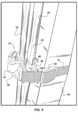
Figure 5 shows the device offigures 1-4 positioned in an engaged position with the elastic portion of the strap exerting a biasing force to hold the two skis in fixed positions relative to each other, and concurrently hold the poles within a ski pole clamp area within the C-shaped member. - Other aspects of the present invention shall be more readily understood when considered in conjunction with the accompanying drawings, and the following detailed description, neither of which should be considered limiting.
- In this description, the directional prepositions of up, upwardly, down, downwardly, front, back, top, upper, bottom, lower, left, right and other such terms refer to the device as it is oriented and appears in the drawings and are used for convenience only. Such prepositions are not intended to be limiting or to imply that the device has to be used or positioned in any particular orientation.
- Now referring to drawings in
figures 1-5 , there is seen inFigure 1 a perspective view of the skiequipment securement device 10 in a disengaged configuration. As shown, thedevice 10 in all modes includes astrap 12 extending from an engagement at a first end to a C-shapedmember 14, to an engagement of a second end of thestrap 12 to aclip 16. While theclip 16 is shown as a hook-like fastener, it may be any fastener which is adapted for a removable connection to a mating fastener located on the C-shapedmember 14 or on thestrap 12 adjacent the C-shapedmember 14. As depicted the fastener is shown as the hook-like clip 16 and the mating fastener is shown as a ring-like clip connector 40. However, such should not be considered in any fashion as other fasteners removably engageable to mating fasteners may be employed such as snaps, buttons, hooks, hook and loop material, or fasteners as would occur to those skilled in the art. - As shown in all figures herein, at least a
first portion 17 of thestrap 12 is formed of elastic material. Elastic strap material is preferred for at least a portion of thestrap 12 to provide a biasing force when thestrap 12 of thedevice 10 is in a stretched engagement encircling ski equipment such asskis 20 and poles 22 (figure 5 ). The provided biasing force from the elongated elastic material, better holds the compressed contacting surfaces of adjacently positionedskis 20 stationary relative to each other. The biasing force also enhances the frictional contact of thestrap 12 where it contacts surfaces of theskis 22, to better hold thestrap 12, and the engageddevice 10, in a fixed position encircling the twoskis 20. Asecond portion 18 of thestrap 12 may be formed of non-elastic material such as nylon or polyester or other woven or non woven belt or strap material such that it maintains substantially a fixed length. By substantially is meant that when stretched thesecond portion 18 maintains its non stretched length plus or minus 10 percent. - While the
strap 12 may be formed entirely of elastic material where thefirst portion 17 of thestrap 12 runs the entire length of thestrap 12 such as infigure 4 , it was found in experimentation that forming the strap in afirst portion 17 which is elastic andsecond portion 18 which is substantially fixed in length, and non-elastic, provided a moredurable device 10, which better frictionally engaged around the exterior surfaces ofskis 20 to which it is adapted to circumferentially engage. - While it was originally thought that the
strap 12 entirely of elastic material would work better to hold thedevice 10 andskis 20 stationary, unexpectedly in experimentation it was found that the non-elasticsecond portion 18 when used, maintained the position of thedevice 10 better when circumferentially contacting the surfaces ofadjacent skis 20 when engaged as infigure 5 . As such, thedevice 10 adapted for engagement aroundadjacent skis 20 andpoles 22 in all modes has at least afirst portion 17 of thestrap 12 formed of elastic material, and preferably has asecond portion 18 of thestrap 12 formed of material which is substantially fixed in length. - Shown in
figure 2 , is an overhead view of a particularly preferred configuration of thedevice 10 where thefirst portion 17 of the strap formed of elastic material is engaged between theclip 16 and aconnection point 24 at a second end of thesecond portion 18 of thestrap 12. While thisconnection point 24 is shown as a connectingmember 26 with twoopenings 28 at opposing ends, it might also be formed by sewing, riveting, or other connections between the second end of thesecond portion 18 of thestrap 12 and one end of thefirst portion 17 of thestrap 12. - As shown in
figure 2 , the employment of a connectingmember 26 withopenings 28 at opposing ends, allows the elasticfirst portion 17 of thestrap 12 to be formed of twosections first portion 17 of thestrap 12. This configuration also allows thesecond portion 18 of thestrap 12 to form a looped connection through theopening 28 of the connectingmember 26, and engage a distal end of thesecond portion 18 of thestrap 12 with anadjustment member 30. Thisadjustment member 30 provides for a length adjustment of thesecond portion 18 of the strap, between a first end thereof engaged with the C-shapedmember 14 and the second end thereof engaged to one end of the elasticfirst portion 17 of thestrap 12. - Additionally shown in
figure 2 , and other figures herein, is a curved recessedramp 32 formed by a recess into theexterior surface 33 of the C-shapedmember 14 in between opposing raised edges, or as shown, shoulders 34. Theramp 34 in the form of such a recess, extends around all of, or at least thecurved area 36 of the C-shapedmember 14. Thisramp 32 provides a secure positioning of the elasticfirst portion 17 of thestrap 12, in between the raised portions orshoulders 34, such that when thedevice 10 is in the engagement with the ski equipment as infigure 5 , thefirst portion 17 of thestrap 12 is located within a recessed pathway 38 (figure 3 ) and will not slide from either side edge of the C-shapedmember 14. -
Figure 3 shows a side view of the device offigures 1-2 and also showing the recessedpathway 36 defined by theramp 32 which is recessed into the exterior 33 surface of the C-shapedmember 14. As can be seen, in moving to the engagement of thedevice 10 as shown infigure 5 , theclip 16 is engaged to aclip connector 40, and pulls and stretches the elasticfirst portion 17 of thestrap 12, which locates into the recess provided by theramp 32. As shown, the recess forming theramp 32 is located in between the opposing raised side edges or shoulders 24 formed on the exterior 33 surface of the C-shapedmember 14. The recess into the exterior surface of the C-shaped member forming aramp 32 is preferred as it maintains the biased contact of the elasticfirst portion 17 of thestrap 12, within and against the surface of theramp 32, which extends around thecurved area 36. - To achieve the removable engagement with ski equipment to which the
device 10 is adapted, when thedevice 10 is circumferentially engaged around two contacting adjacently positionedskis 20, as infigure 5 , theclip 16 is pulled to stretch thefirst portion 17 of thestrap 12, which settles into the recess and on the surface of theramp 32, as theclip 16 is engaged to theclip connector 40. The biasing force exerted by the stretched elasticfirst portion 17 of thestrap 12 is communicated to thesecond portion 18 of thestrap 12, which frictionally contacts against portions of exterior surface of the twoskis 20. The contact against the surfaces of the two adjacent skis holds theskis 20 in position relative to each other, and also holds thedevice 10 in a fixed position encircling bothskis 20. - As shown in
Figure 4 the portion of thestrap 12 formed of elastic material, can include the entire length of thestrap 12. In this mode, as can be discerned, the elastic material is formed by afirst section 17a extending between the engagement to theclip 16 and the C-shapedmember 14. Thesecond section 17b (not shown) will extend from theclip 16 to theadjustment member 30. - As noted,
Figure 5 shows thedevice 10 offigures 1-4 , positioned in an engaged position with ski equipment such as twoskis 20 adjacent and in contact with each other, and one or a plurality ofpoles 22. As shown infigure 5 andfigures 1 and 3 herein, a pole clamping area is formed by anopening 42 formed between opposing sides of the C-shapedmember 14, and apassage 44 provides access for thepoles 22 into and out of theopening 42. - With the
device 10 in the engaged position offigure 5 , a portion of thestrap 12 encircling theskis 20, is positioned to block thepassage 44 and thereby maintain thepoles 22 within theopening 42 as long as thedevice 10 is located to the engaged position.Ski poles 22 as is well known, conventionally have handles on one end opposite a tip on the other end. At the tip end, what is known as a basket which is the disc like object just above the tip, surrounds the pole and is so positioned to stop the ski pole from sinking too far into the snow. Also well known and not shown are loops located on each handle of ski poles to secure them to the wrists of the user. - As shown, with the diameter of the
opening 42 being substantially equal to that of thepoles 22 to which theopening 42 is adapted to encircle, or at least smaller than a diameter of the handle and/or the basket on thepoles 22, thepoles 22 cannot slide out of opening 42 along the axis of thepoles 22. Further, with thestrap 12 blocking thepassage 44, thepoles 22 cannot move out of theopening 42 through thepassage 44. Additionally, as noted, one or both of the ski handle loops may first be engaged to encircle both skis to provide an engagement of the handle ends of the poles to the skis to hold thepoles 22 substantially parallel to theskis 20 when thedevice 10 is in the engaged position offigure 5 . - As such, with the
device 10, in the engaged position offigure 5 , it is held in a substantially fixed engagement at a mounting position on theskis 20 which are encircled by thestrap 12, and thepoles 12 are held within theopening 42 by the blocking of thepassage 44 by the encirclingstrap 12. Thus, the user may hold thepoles 22, and thereby carry theskis 20 comfortably and easily with one hand. - Further, while the C-shaped
member 14 may be formed of metal or polymeric or other material having the strength and durability to handle the ongoing engagement with ski equipment, in another preferred mode, the material forming the C-shaped member is sufficiently flexible to allow a deflection and move one or both of afirst member section 46 on one side of thepassage 44 and asecond member section 48 on the opposing side of thepassage 44 closer to each other. This deflection will narrow the gap forming thepassage 44 and will also narrow a diameter D (figure 3 ) of theopening 42 which is situated in between thefirst member section 46 andsecond member section 48. - The narrowing of the diameter D of the
opening 42, causes thefirst member section 46 and/orsecond member section 48, to deflect, and thereby form a compressive engagement with sides of thepoles 22 located within theopening 42 with aninterior surface 43 forming theopening 42. This forms a more secure engagement with thepoles 22 to which thedevice 10 is adapted to removably engage along with theskis 20. - While all of the fundamental characteristics and features of the removably engageable ski equipment securement device have been shown and described herein, with reference to particular embodiments thereof, a latitude of modification, various changes and substitutions are intended in the foregoing disclosure and it will be apparent that in some instances, some features of the invention may be employed without a corresponding use of other features without departing from the scope of the invention as set forth. The scope of the invention as defined by the following claims.
Claims (6)
- A ski equipment securement apparatus (10), comprising:a substantially C-shaped member (14) having a body, said body having a first member section (46) and a second member section (48);said second member section extending from a first end of said body, to a curved area (36) of said body;said first member section extending from said curved area to a distal end thereof; said body having an exterior surface (33) opposite an interior surface (43);said interior surface defining an opening (42) situated between said first member section and said second member section, said opening accessible through a passage (44) located in-between said distal end of said first member section and said second member section;a strap (12), said strap in a connection at a first end thereof, with said first end of said body;a second end of said strap in a connection to a clip (16);a clip connector (40) positioned at or adjacent said first end of said strap;a removable engagement of said clip to said clip connector positioning a portion of said strap in a side surface contact with said exterior surface of said body of said C-shaped member along a curved pathway (38), said curved pathway extending around said curved portion upon said second member section;said C-shaped member adapted for positioning to an engaged position with at least one ski pole positioned within said opening, and with said clip in said removable engagement with said clip connector, to thereby hold said strap in an encircling contact against exterior surfaces of a pair of skis, whereby a said pole within said opening is employable as a handle to carry said skis while said C-shaped member is in said engaged position; characterized in that the apparatus additionally comprises:a recess (36) formed in said exterior surface of said body of said C-shaped member, said recess located along said curved pathway; andsaid side surface contact of said strap with said exterior surface of said body along said pathway, being within said recess.
- The ski equipment securement apparatus of claim 1, additionally comprising:
said recess defined by ribs (34) positioned on opposing sides of said recess along said curved pathway. - The ski equipment securement apparatus of claim 1 or 2, additionally comprising:said strap having a first portion (18), and having a second portion (17) formed of elastic material;said elastic material during said positioning to an engaged position imparting compression to said encircling contact of said strap with said exterior surfaces of said pair of skis to form a compressive encircling contact with exterior surfaces of a pair of skis.
- The ski equipment securement apparatus of claim 3, additionally comprising:
said second portion of said strap formed of a first section (17a) of elastic material engaged between a connection point with said first portion of said strap and said clip, and a second section (17b) of elastic material engaged between said connection point and said clip. - The ski equipment securement apparatus of claim 3 or 4, additionally comprising:
said elastic material forming a biased said side surface contact with said exterior surface of said body within said recess. - The ski equipment securement apparatus of any one of the claims 1, 3 or 5 additionally comprising:
said body of said C-shaped member being formed of pliable material; and movement of said first member section toward said second member section with said C-shaped member in said engaged position, imparting a compressing contact of said interior surface defining said opening against exterior surfaces of a ski pole therein.
Applications Claiming Priority (2)
| Application Number | Priority Date | Filing Date | Title |
|---|---|---|---|
| US201862642246P | 2018-03-13 | 2018-03-13 | |
| PCT/US2019/022091 WO2019178258A1 (en) | 2018-03-13 | 2019-03-13 | Snow ski equipment securement device |
Publications (3)
| Publication Number | Publication Date |
|---|---|
| EP3765164A1 EP3765164A1 (en) | 2021-01-20 |
| EP3765164A4 EP3765164A4 (en) | 2021-12-22 |
| EP3765164B1 true EP3765164B1 (en) | 2025-01-22 |
Family
ID=67908131
Family Applications (1)
| Application Number | Title | Priority Date | Filing Date |
|---|---|---|---|
| EP19767114.2A Active EP3765164B1 (en) | 2018-03-13 | 2019-03-13 | Snow ski equipment securement device |
Country Status (5)
| Country | Link |
|---|---|
| US (1) | US11766600B2 (en) |
| EP (1) | EP3765164B1 (en) |
| JP (1) | JP7387621B2 (en) |
| CA (1) | CA3092997A1 (en) |
| WO (1) | WO2019178258A1 (en) |
Families Citing this family (2)
| Publication number | Priority date | Publication date | Assignee | Title |
|---|---|---|---|---|
| JP1672711S (en) * | 2020-05-08 | 2020-11-16 | ||
| JP1672713S (en) * | 2020-05-08 | 2020-11-16 |
Family Cites Families (12)
| Publication number | Priority date | Publication date | Assignee | Title |
|---|---|---|---|---|
| JPS5011666U (en) * | 1973-05-29 | 1975-02-06 | ||
| US3976234A (en) * | 1974-09-23 | 1976-08-24 | Amphora Enterprises Inc. | Portable ski and ski pole carrying apparatus |
| JPS5225269Y2 (en) * | 1975-04-01 | 1977-06-08 | ||
| US4120437A (en) * | 1977-05-09 | 1978-10-17 | Hara Clarence M | Carrier for skis and ski poles |
| US4165027A (en) * | 1978-02-21 | 1979-08-21 | Briggs Robert W | Ski and ski pole assembly |
| USD288032S (en) * | 1984-06-15 | 1987-02-03 | Gainey Michael D | Ski and ski pole carrier |
| US4620722A (en) * | 1984-06-22 | 1986-11-04 | Dunn Stephen H | Ski and pole holder |
| FR2740696B1 (en) * | 1995-11-02 | 1998-02-06 | Michalon Gerard Jean | RETRACTABLE DEVICE FOR FACILITATING THE STORAGE AND HANDLING OF A PAIR OF SKIS AND POLES |
| US20040169054A1 (en) * | 2003-02-28 | 2004-09-02 | Edmund Chan | Ski carrying strap |
| US9560909B2 (en) * | 2014-12-01 | 2017-02-07 | John Krpan | Garment strap clip |
| WO2017091906A1 (en) * | 2015-12-02 | 2017-06-08 | Keohane Edmund Mark | Ski strap and hanging device |
| WO2017223410A1 (en) * | 2016-06-24 | 2017-12-28 | Vacovec John | Ski pole locking system and methods of use for carrying skis |
-
2019
- 2019-03-13 US US16/756,123 patent/US11766600B2/en active Active
- 2019-03-13 JP JP2020549638A patent/JP7387621B2/en active Active
- 2019-03-13 EP EP19767114.2A patent/EP3765164B1/en active Active
- 2019-03-13 WO PCT/US2019/022091 patent/WO2019178258A1/en not_active Ceased
- 2019-03-13 CA CA3092997A patent/CA3092997A1/en active Pending
Also Published As
| Publication number | Publication date |
|---|---|
| US20210370159A1 (en) | 2021-12-02 |
| US11766600B2 (en) | 2023-09-26 |
| EP3765164A1 (en) | 2021-01-20 |
| JP2021517489A (en) | 2021-07-26 |
| JP7387621B2 (en) | 2023-11-28 |
| WO2019178258A1 (en) | 2019-09-19 |
| EP3765164A4 (en) | 2021-12-22 |
| CA3092997A1 (en) | 2019-09-19 |
Similar Documents
| Publication | Publication Date | Title |
|---|---|---|
| US5762242A (en) | Ski carrying system | |
| US8616600B2 (en) | Portable ski carrier | |
| US4120437A (en) | Carrier for skis and ski poles | |
| US5312134A (en) | Ski glove/grip interlock system | |
| US5470108A (en) | Ski pole grip assembly | |
| US5516150A (en) | Ski glove/grip interlock system | |
| EP3171949B1 (en) | Carrying device for ski equipment | |
| EP2268370A1 (en) | Integrated pole-to-ski coupling arrangement | |
| CA1156691A (en) | Snowshoe | |
| US11766600B2 (en) | Ski pole equipment securement device | |
| US8746769B2 (en) | Portable ski and ski pole carrier system | |
| US20110006090A1 (en) | Backpack | |
| US20080018063A1 (en) | Device for towing a trolley | |
| US9993717B2 (en) | Skin cleat | |
| US5178413A (en) | Ski pole supporting assembly | |
| US4458935A (en) | Ski equipment carrier | |
| EP4247505B1 (en) | Connection system for a ski pole | |
| EP3204130B1 (en) | Sling carrier for skis and ski boots | |
| US9656151B2 (en) | Skin cleat | |
| US11045711B2 (en) | Ski management device | |
| JP2005507293A (en) | Transport equipment | |
| JPH0739614A (en) | Connection structure between ski grip and ski gloves, and ski stock | |
| CA2230168A1 (en) | Trolley for transporting snow skiing equipment | |
| WO2004043553A1 (en) | A ski carrying device | |
| GB2556407A (en) | Improved front-back pack |
Legal Events
| Date | Code | Title | Description |
|---|---|---|---|
| STAA | Information on the status of an ep patent application or granted ep patent |
Free format text: STATUS: THE INTERNATIONAL PUBLICATION HAS BEEN MADE |
|
| PUAI | Public reference made under article 153(3) epc to a published international application that has entered the european phase |
Free format text: ORIGINAL CODE: 0009012 |
|
| STAA | Information on the status of an ep patent application or granted ep patent |
Free format text: STATUS: REQUEST FOR EXAMINATION WAS MADE |
|
| 17P | Request for examination filed |
Effective date: 20201008 |
|
| AK | Designated contracting states |
Kind code of ref document: A1 Designated state(s): AL AT BE BG CH CY CZ DE DK EE ES FI FR GB GR HR HU IE IS IT LI LT LU LV MC MK MT NL NO PL PT RO RS SE SI SK SM TR |
|
| AX | Request for extension of the european patent |
Extension state: BA ME |
|
| DAV | Request for validation of the european patent (deleted) | ||
| DAX | Request for extension of the european patent (deleted) | ||
| A4 | Supplementary search report drawn up and despatched |
Effective date: 20211119 |
|
| RIC1 | Information provided on ipc code assigned before grant |
Ipc: A45C 13/30 20060101ALI20211115BHEP Ipc: A63C 11/00 20060101ALI20211115BHEP Ipc: A45F 3/14 20060101ALI20211115BHEP Ipc: A41F 15/00 20060101ALI20211115BHEP Ipc: A63C 11/02 20060101AFI20211115BHEP |
|
| GRAP | Despatch of communication of intention to grant a patent |
Free format text: ORIGINAL CODE: EPIDOSNIGR1 |
|
| STAA | Information on the status of an ep patent application or granted ep patent |
Free format text: STATUS: GRANT OF PATENT IS INTENDED |
|
| RIC1 | Information provided on ipc code assigned before grant |
Ipc: A45C 13/30 20060101ALI20240711BHEP Ipc: A63C 11/00 20060101ALI20240711BHEP Ipc: A45F 3/14 20060101ALI20240711BHEP Ipc: A41F 15/00 20060101ALI20240711BHEP Ipc: A63C 11/02 20060101AFI20240711BHEP |
|
| INTG | Intention to grant announced |
Effective date: 20240814 |
|
| GRAS | Grant fee paid |
Free format text: ORIGINAL CODE: EPIDOSNIGR3 |
|
| GRAA | (expected) grant |
Free format text: ORIGINAL CODE: 0009210 |
|
| STAA | Information on the status of an ep patent application or granted ep patent |
Free format text: STATUS: THE PATENT HAS BEEN GRANTED |
|
| AK | Designated contracting states |
Kind code of ref document: B1 Designated state(s): AL AT BE BG CH CY CZ DE DK EE ES FI FR GB GR HR HU IE IS IT LI LT LU LV MC MK MT NL NO PL PT RO RS SE SI SK SM TR |
|
| REG | Reference to a national code |
Ref country code: GB Ref legal event code: FG4D |
|
| REG | Reference to a national code |
Ref country code: CH Ref legal event code: EP |
|
| REG | Reference to a national code |
Ref country code: IE Ref legal event code: FG4D |
|
| REG | Reference to a national code |
Ref country code: DE Ref legal event code: R096 Ref document number: 602019065117 Country of ref document: DE |
|
| REG | Reference to a national code |
Ref country code: NL Ref legal event code: MP Effective date: 20250122 |
|
| PG25 | Lapsed in a contracting state [announced via postgrant information from national office to epo] |
Ref country code: NL Free format text: LAPSE BECAUSE OF FAILURE TO SUBMIT A TRANSLATION OF THE DESCRIPTION OR TO PAY THE FEE WITHIN THE PRESCRIBED TIME-LIMIT Effective date: 20250122 |
|
| PG25 | Lapsed in a contracting state [announced via postgrant information from national office to epo] |
Ref country code: RS Free format text: LAPSE BECAUSE OF FAILURE TO SUBMIT A TRANSLATION OF THE DESCRIPTION OR TO PAY THE FEE WITHIN THE PRESCRIBED TIME-LIMIT Effective date: 20250422 |
|
| PG25 | Lapsed in a contracting state [announced via postgrant information from national office to epo] |
Ref country code: FI Free format text: LAPSE BECAUSE OF FAILURE TO SUBMIT A TRANSLATION OF THE DESCRIPTION OR TO PAY THE FEE WITHIN THE PRESCRIBED TIME-LIMIT Effective date: 20250122 |
|
| PG25 | Lapsed in a contracting state [announced via postgrant information from national office to epo] |
Ref country code: PL Free format text: LAPSE BECAUSE OF FAILURE TO SUBMIT A TRANSLATION OF THE DESCRIPTION OR TO PAY THE FEE WITHIN THE PRESCRIBED TIME-LIMIT Effective date: 20250122 |
|
| PG25 | Lapsed in a contracting state [announced via postgrant information from national office to epo] |
Ref country code: ES Free format text: LAPSE BECAUSE OF FAILURE TO SUBMIT A TRANSLATION OF THE DESCRIPTION OR TO PAY THE FEE WITHIN THE PRESCRIBED TIME-LIMIT Effective date: 20250122 |
|
| REG | Reference to a national code |
Ref country code: LT Ref legal event code: MG9D |
|
| PG25 | Lapsed in a contracting state [announced via postgrant information from national office to epo] |
Ref country code: NO Free format text: LAPSE BECAUSE OF FAILURE TO SUBMIT A TRANSLATION OF THE DESCRIPTION OR TO PAY THE FEE WITHIN THE PRESCRIBED TIME-LIMIT Effective date: 20250422 Ref country code: IS Free format text: LAPSE BECAUSE OF FAILURE TO SUBMIT A TRANSLATION OF THE DESCRIPTION OR TO PAY THE FEE WITHIN THE PRESCRIBED TIME-LIMIT Effective date: 20250522 |
|
| PGFP | Annual fee paid to national office [announced via postgrant information from national office to epo] |
Ref country code: IT Payment date: 20250422 Year of fee payment: 7 |
|
| REG | Reference to a national code |
Ref country code: AT Ref legal event code: MK05 Ref document number: 1761054 Country of ref document: AT Kind code of ref document: T Effective date: 20250122 |
|
| PG25 | Lapsed in a contracting state [announced via postgrant information from national office to epo] |
Ref country code: HR Free format text: LAPSE BECAUSE OF FAILURE TO SUBMIT A TRANSLATION OF THE DESCRIPTION OR TO PAY THE FEE WITHIN THE PRESCRIBED TIME-LIMIT Effective date: 20250122 |
|
| PG25 | Lapsed in a contracting state [announced via postgrant information from national office to epo] |
Ref country code: LV Free format text: LAPSE BECAUSE OF FAILURE TO SUBMIT A TRANSLATION OF THE DESCRIPTION OR TO PAY THE FEE WITHIN THE PRESCRIBED TIME-LIMIT Effective date: 20250122 Ref country code: PT Free format text: LAPSE BECAUSE OF FAILURE TO SUBMIT A TRANSLATION OF THE DESCRIPTION OR TO PAY THE FEE WITHIN THE PRESCRIBED TIME-LIMIT Effective date: 20250522 |
|
| PG25 | Lapsed in a contracting state [announced via postgrant information from national office to epo] |
Ref country code: BG Free format text: LAPSE BECAUSE OF FAILURE TO SUBMIT A TRANSLATION OF THE DESCRIPTION OR TO PAY THE FEE WITHIN THE PRESCRIBED TIME-LIMIT Effective date: 20250122 Ref country code: GR Free format text: LAPSE BECAUSE OF FAILURE TO SUBMIT A TRANSLATION OF THE DESCRIPTION OR TO PAY THE FEE WITHIN THE PRESCRIBED TIME-LIMIT Effective date: 20250423 |
|
| PG25 | Lapsed in a contracting state [announced via postgrant information from national office to epo] |
Ref country code: AT Free format text: LAPSE BECAUSE OF FAILURE TO SUBMIT A TRANSLATION OF THE DESCRIPTION OR TO PAY THE FEE WITHIN THE PRESCRIBED TIME-LIMIT Effective date: 20250122 |
|
| PG25 | Lapsed in a contracting state [announced via postgrant information from national office to epo] |
Ref country code: SE Free format text: LAPSE BECAUSE OF FAILURE TO SUBMIT A TRANSLATION OF THE DESCRIPTION OR TO PAY THE FEE WITHIN THE PRESCRIBED TIME-LIMIT Effective date: 20250122 |
|
| REG | Reference to a national code |
Ref country code: DE Ref legal event code: R119 Ref document number: 602019065117 Country of ref document: DE |
|
| PG25 | Lapsed in a contracting state [announced via postgrant information from national office to epo] |
Ref country code: SM Free format text: LAPSE BECAUSE OF FAILURE TO SUBMIT A TRANSLATION OF THE DESCRIPTION OR TO PAY THE FEE WITHIN THE PRESCRIBED TIME-LIMIT Effective date: 20250122 |
|
| PG25 | Lapsed in a contracting state [announced via postgrant information from national office to epo] |
Ref country code: DK Free format text: LAPSE BECAUSE OF FAILURE TO SUBMIT A TRANSLATION OF THE DESCRIPTION OR TO PAY THE FEE WITHIN THE PRESCRIBED TIME-LIMIT Effective date: 20250122 |
|
| PG25 | Lapsed in a contracting state [announced via postgrant information from national office to epo] |
Ref country code: MC Free format text: LAPSE BECAUSE OF FAILURE TO SUBMIT A TRANSLATION OF THE DESCRIPTION OR TO PAY THE FEE WITHIN THE PRESCRIBED TIME-LIMIT Effective date: 20250122 |
|
| PG25 | Lapsed in a contracting state [announced via postgrant information from national office to epo] |
Ref country code: EE Free format text: LAPSE BECAUSE OF FAILURE TO SUBMIT A TRANSLATION OF THE DESCRIPTION OR TO PAY THE FEE WITHIN THE PRESCRIBED TIME-LIMIT Effective date: 20250122 Ref country code: CZ Free format text: LAPSE BECAUSE OF FAILURE TO SUBMIT A TRANSLATION OF THE DESCRIPTION OR TO PAY THE FEE WITHIN THE PRESCRIBED TIME-LIMIT Effective date: 20250122 |
|
| REG | Reference to a national code |
Ref country code: CH Ref legal event code: H13 Free format text: ST27 STATUS EVENT CODE: U-0-0-H10-H13 (AS PROVIDED BY THE NATIONAL OFFICE) Effective date: 20251023 |
|
| PG25 | Lapsed in a contracting state [announced via postgrant information from national office to epo] |
Ref country code: RO Free format text: LAPSE BECAUSE OF FAILURE TO SUBMIT A TRANSLATION OF THE DESCRIPTION OR TO PAY THE FEE WITHIN THE PRESCRIBED TIME-LIMIT Effective date: 20250122 |
|
| PG25 | Lapsed in a contracting state [announced via postgrant information from national office to epo] |
Ref country code: SK Free format text: LAPSE BECAUSE OF FAILURE TO SUBMIT A TRANSLATION OF THE DESCRIPTION OR TO PAY THE FEE WITHIN THE PRESCRIBED TIME-LIMIT Effective date: 20250122 |
|
| PG25 | Lapsed in a contracting state [announced via postgrant information from national office to epo] |
Ref country code: LU Free format text: LAPSE BECAUSE OF NON-PAYMENT OF DUE FEES Effective date: 20250313 |
|
| PLBE | No opposition filed within time limit |
Free format text: ORIGINAL CODE: 0009261 |
|
| STAA | Information on the status of an ep patent application or granted ep patent |
Free format text: STATUS: NO OPPOSITION FILED WITHIN TIME LIMIT |
|
| REG | Reference to a national code |
Ref country code: BE Ref legal event code: MM Effective date: 20250331 |
|
| GBPC | Gb: european patent ceased through non-payment of renewal fee |
Effective date: 20250422 |
|
| 26N | No opposition filed |
Effective date: 20251023 |
|
| PG25 | Lapsed in a contracting state [announced via postgrant information from national office to epo] |
Ref country code: DE Free format text: LAPSE BECAUSE OF NON-PAYMENT OF DUE FEES Effective date: 20251001 |
|
| PG25 | Lapsed in a contracting state [announced via postgrant information from national office to epo] |
Ref country code: GB Free format text: LAPSE BECAUSE OF NON-PAYMENT OF DUE FEES Effective date: 20250422 |
|
| PG25 | Lapsed in a contracting state [announced via postgrant information from national office to epo] |
Ref country code: FR Free format text: LAPSE BECAUSE OF NON-PAYMENT OF DUE FEES Effective date: 20250322 |
|
| PG25 | Lapsed in a contracting state [announced via postgrant information from national office to epo] |
Ref country code: BE Free format text: LAPSE BECAUSE OF NON-PAYMENT OF DUE FEES Effective date: 20250331 |
|
| PG25 | Lapsed in a contracting state [announced via postgrant information from national office to epo] |
Ref country code: CH Free format text: LAPSE BECAUSE OF NON-PAYMENT OF DUE FEES Effective date: 20250331 |
|
| PG25 | Lapsed in a contracting state [announced via postgrant information from national office to epo] |
Ref country code: IE Free format text: LAPSE BECAUSE OF NON-PAYMENT OF DUE FEES Effective date: 20250313 |