EP3764742A1 - Self-baking electrode for submerged electric arc furnaces comprising a center column - Google Patents
Self-baking electrode for submerged electric arc furnaces comprising a center column Download PDFInfo
- Publication number
- EP3764742A1 EP3764742A1 EP19717961.7A EP19717961A EP3764742A1 EP 3764742 A1 EP3764742 A1 EP 3764742A1 EP 19717961 A EP19717961 A EP 19717961A EP 3764742 A1 EP3764742 A1 EP 3764742A1
- Authority
- EP
- European Patent Office
- Prior art keywords
- self
- electric arc
- electrode
- arc furnaces
- center column
- Prior art date
- Legal status (The legal status is an assumption and is not a legal conclusion. Google has not performed a legal analysis and makes no representation as to the accuracy of the status listed.)
- Withdrawn
Links
- 238000010891 electric arc Methods 0.000 title claims abstract description 21
- OKTJSMMVPCPJKN-UHFFFAOYSA-N Carbon Chemical group [C] OKTJSMMVPCPJKN-UHFFFAOYSA-N 0.000 claims abstract description 47
- XEEYBQQBJWHFJM-UHFFFAOYSA-N Iron Chemical compound [Fe] XEEYBQQBJWHFJM-UHFFFAOYSA-N 0.000 claims abstract description 29
- 229910052742 iron Inorganic materials 0.000 claims abstract description 15
- VNWKTOKETHGBQD-UHFFFAOYSA-N methane Chemical compound C VNWKTOKETHGBQD-UHFFFAOYSA-N 0.000 claims abstract description 14
- 229920000049 Carbon (fiber) Polymers 0.000 claims abstract description 11
- 239000004917 carbon fiber Substances 0.000 claims abstract description 11
- 239000002243 precursor Substances 0.000 claims abstract description 8
- HBMJWWWQQXIZIP-UHFFFAOYSA-N silicon carbide Chemical compound [Si+]#[C-] HBMJWWWQQXIZIP-UHFFFAOYSA-N 0.000 claims abstract description 6
- 229910010271 silicon carbide Inorganic materials 0.000 claims abstract description 6
- 229910002804 graphite Inorganic materials 0.000 claims description 35
- XUIMIQQOPSSXEZ-UHFFFAOYSA-N Silicon Chemical compound [Si] XUIMIQQOPSSXEZ-UHFFFAOYSA-N 0.000 claims description 28
- 239000010439 graphite Substances 0.000 claims description 27
- 229910052710 silicon Inorganic materials 0.000 claims description 21
- 239000010703 silicon Substances 0.000 claims description 21
- 229910052799 carbon Inorganic materials 0.000 claims description 18
- 239000007769 metal material Substances 0.000 claims description 9
- 239000000463 material Substances 0.000 claims description 8
- 229910021364 Al-Si alloy Inorganic materials 0.000 claims description 7
- 238000009826 distribution Methods 0.000 claims description 5
- 239000002245 particle Substances 0.000 claims description 5
- 229910000838 Al alloy Inorganic materials 0.000 claims description 4
- 239000000945 filler Substances 0.000 claims description 4
- 239000000203 mixture Substances 0.000 claims description 4
- 239000011863 silicon-based powder Substances 0.000 claims description 2
- 239000002131 composite material Substances 0.000 abstract description 15
- 229910052782 aluminium Inorganic materials 0.000 abstract description 12
- XAGFODPZIPBFFR-UHFFFAOYSA-N aluminium Chemical compound [Al] XAGFODPZIPBFFR-UHFFFAOYSA-N 0.000 abstract description 12
- CSDREXVUYHZDNP-UHFFFAOYSA-N alumanylidynesilicon Chemical compound [Al].[Si] CSDREXVUYHZDNP-UHFFFAOYSA-N 0.000 abstract description 5
- 229910000676 Si alloy Inorganic materials 0.000 abstract description 4
- 229910052751 metal Inorganic materials 0.000 description 9
- 239000002184 metal Substances 0.000 description 9
- 239000007787 solid Substances 0.000 description 8
- 229910001021 Ferroalloy Inorganic materials 0.000 description 7
- 239000007788 liquid Substances 0.000 description 7
- 238000004519 manufacturing process Methods 0.000 description 6
- 230000008018 melting Effects 0.000 description 6
- 238000002844 melting Methods 0.000 description 6
- 238000006243 chemical reaction Methods 0.000 description 5
- 239000012071 phase Substances 0.000 description 5
- VYPSYNLAJGMNEJ-UHFFFAOYSA-N silicon dioxide Inorganic materials O=[Si]=O VYPSYNLAJGMNEJ-UHFFFAOYSA-N 0.000 description 5
- 229910018125 Al-Si Inorganic materials 0.000 description 4
- 229910018520 Al—Si Inorganic materials 0.000 description 4
- 239000000956 alloy Substances 0.000 description 4
- 238000011109 contamination Methods 0.000 description 4
- 239000000155 melt Substances 0.000 description 4
- 238000007711 solidification Methods 0.000 description 4
- 230000008023 solidification Effects 0.000 description 4
- 229910045601 alloy Inorganic materials 0.000 description 3
- 238000005452 bending Methods 0.000 description 3
- 238000010586 diagram Methods 0.000 description 3
- 238000005516 engineering process Methods 0.000 description 3
- IJGRMHOSHXDMSA-UHFFFAOYSA-N Atomic nitrogen Chemical compound N#N IJGRMHOSHXDMSA-UHFFFAOYSA-N 0.000 description 2
- 229910002796 Si–Al Inorganic materials 0.000 description 2
- 239000011294 coal tar pitch Substances 0.000 description 2
- 239000000356 contaminant Substances 0.000 description 2
- 210000002445 nipple Anatomy 0.000 description 2
- 239000011148 porous material Substances 0.000 description 2
- 239000000377 silicon dioxide Substances 0.000 description 2
- 235000012239 silicon dioxide Nutrition 0.000 description 2
- 238000012360 testing method Methods 0.000 description 2
- 229910001366 Hypereutectic aluminum Inorganic materials 0.000 description 1
- QVGXLLKOCUKJST-UHFFFAOYSA-N atomic oxygen Chemical compound [O] QVGXLLKOCUKJST-UHFFFAOYSA-N 0.000 description 1
- 239000011230 binding agent Substances 0.000 description 1
- 239000013078 crystal Substances 0.000 description 1
- 230000007812 deficiency Effects 0.000 description 1
- 230000005496 eutectics Effects 0.000 description 1
- 230000003203 everyday effect Effects 0.000 description 1
- 239000007789 gas Substances 0.000 description 1
- 239000007791 liquid phase Substances 0.000 description 1
- 150000001247 metal acetylides Chemical class 0.000 description 1
- 229910021471 metal-silicon alloy Inorganic materials 0.000 description 1
- 238000000034 method Methods 0.000 description 1
- 229910052757 nitrogen Inorganic materials 0.000 description 1
- 230000003647 oxidation Effects 0.000 description 1
- 238000007254 oxidation reaction Methods 0.000 description 1
- 239000001301 oxygen Substances 0.000 description 1
- 229910052760 oxygen Inorganic materials 0.000 description 1
- 239000000843 powder Substances 0.000 description 1
- 238000003825 pressing Methods 0.000 description 1
- 239000010453 quartz Substances 0.000 description 1
- 239000002210 silicon-based material Substances 0.000 description 1
- 239000011343 solid material Substances 0.000 description 1
- 238000005507 spraying Methods 0.000 description 1
- 230000009897 systematic effect Effects 0.000 description 1
Images



Classifications
-
- H—ELECTRICITY
- H05—ELECTRIC TECHNIQUES NOT OTHERWISE PROVIDED FOR
- H05B—ELECTRIC HEATING; ELECTRIC LIGHT SOURCES NOT OTHERWISE PROVIDED FOR; CIRCUIT ARRANGEMENTS FOR ELECTRIC LIGHT SOURCES, IN GENERAL
- H05B7/00—Heating by electric discharge
- H05B7/02—Details
- H05B7/06—Electrodes
- H05B7/08—Electrodes non-consumable
-
- H—ELECTRICITY
- H05—ELECTRIC TECHNIQUES NOT OTHERWISE PROVIDED FOR
- H05B—ELECTRIC HEATING; ELECTRIC LIGHT SOURCES NOT OTHERWISE PROVIDED FOR; CIRCUIT ARRANGEMENTS FOR ELECTRIC LIGHT SOURCES, IN GENERAL
- H05B7/00—Heating by electric discharge
- H05B7/02—Details
- H05B7/06—Electrodes
- H05B7/08—Electrodes non-consumable
- H05B7/085—Electrodes non-consumable mainly consisting of carbon
- H05B7/09—Self-baking electrodes, e.g. Söderberg type electrodes
-
- H—ELECTRICITY
- H05—ELECTRIC TECHNIQUES NOT OTHERWISE PROVIDED FOR
- H05B—ELECTRIC HEATING; ELECTRIC LIGHT SOURCES NOT OTHERWISE PROVIDED FOR; CIRCUIT ARRANGEMENTS FOR ELECTRIC LIGHT SOURCES, IN GENERAL
- H05B7/00—Heating by electric discharge
- H05B7/02—Details
- H05B7/06—Electrodes
- H05B7/08—Electrodes non-consumable
- H05B7/085—Electrodes non-consumable mainly consisting of carbon
Definitions
- the central column object of the present invention replaces the conventional graphite center or central column of composite self-baking electrodes which are used for the production in a submerged arc furnace of silicon metal and also of other ferroalloys, a concentric hollow metallic column with the outer casing of the electrode being defined in this invention, and in which the same double sliding system of the composite electrode can be applied.
- This central column has a shape particular to favor mechanical support and the baking of the carbon paste either in the form of a tube with fins or else star-shaped, and it is manufactured from metallic materials that are not contaminating for the silicon due to the similarity of composition, and preferably with a hypereutectic aluminum-silicon alloy.
- this metallic column could also be manufactured with iron.
- a precursor for silicon carbide to fill the hollow generated by the melting of the metallic structure in the lower part of the electrode, where the hollow can be filled with a baked carbon electrode.
- the field of application of the present invention is the industrial sector of the silicon metal and ferroalloys produced in a submerged electric arc furnace.
- electrodes are known to be one of the fundamental elements.
- electrodes are made up of a carbon mass that transmits electric current to the bottom of the furnace where the electric arc is produced between the electrode and the hearth of the furnace, whereby producing the energy needed to reduce the ores, generally in the form of oxides, and obtaining the product, for example: of quartz, which is silicon dioxide (SiO 2 ), by reaction with carbon and consuming a large amount of energy, silicon is obtained.
- quartz which is silicon dioxide (SiO 2 )
- This arc wears the electrode, which is replaced at the upper part of the column and gradually descends as it is consumed.
- Electrodes There are several types of electrodes, ranging from the so-called pre-baked electrodes, the state and shape of which do not vary in the column because they were already subjected to baking at the producer's factory, such as graphite electrodes, and in contrast, there are those electrodes which are baked with the heat itself from the furnace as they descend the column, usually referred to as self-baking electrodes, with two types in turn standing out: those referred to as Soderberg-type paste electrodes having as their only elements the casing and the carbon paste which is baked inside the casing, and those referred to as composite electrodes because part of the electrode is pre-baked and part is baked as it descends with the operating heat of the furnace itself.
- Soderberg-type electrodes are formed by a metallic casing which is used as a shell of the Soderberg paste, which is a mixture of various particle size distributions of various types of carbon together with a coal-tar pitch acting as a binder.
- Coal-tar pitch liquefies between 60 and 100 °C, such that when the paste being transported and used as a solid material enters the upper part of the electrode column at room temperature, it is converted into a liquid which completely fills the casing when exceeding 100 °C at about four meters in height above the furnace.
- the paste hardens again, being baked with the round shape of the casing and maintaining this structure when the casing melts and is introduced in the mixture of the furnace until being consumed in the electric arc of the lower part of the electrode.
- the weight of the entire carbon mass making up the paste is supported by the casing, which has on its inner surface a series of suitably perforated metallic fins where the paste bonds when it bakes and entails the mechanical support of any baked and unbaked paste. These fins are welded to the casing, descend together with it and also melt in the lower part of the electrode, but when the paste is already well baked.
- the principle of the operation and introduction of the electrodes in the furnace as they are consumed by the arc in the lower part is by means of sliding rings, which are generally two in number: the fixed ring and the mobile ring, and they have their own structure 8 meters above the furnace which is part of the structure of the electrode column.
- the weight of the entire electrode column being consumed is usually supported by the two rings, but when sliding is to be done from the standby position, the movements are: the fixed ring opens, the closed mobile ring slides or drops down, which pulls the electrode and introduces it in the furnace at the programmed length, the fixed ring which will support the entire electrode closes, while the mobile ring opens and moves up to the standby position, where it closes, leaving the two rings in the original location.
- the sliding rings are always in the same site of the column, what pulls the mobile ring is the metallic casing inside which is the carbon paste with the corresponding phase change from solid to liquid and back to solid, according to the height
- the casing can have on its surface a series of metallic fins where the paste bonds when it bakes and entails the mechanical support of the entire weight of the paste located above the baking area. These fins are welded to the casing, descend together with it and also melt in the lower part of the electrode.
- the mechanical support of the column is trusted to the bonding between the central graphite electrode and the paste as it bakes.
- the baked paste area is higher around the graphite than on its outer surface which is in contact with the casing.
- graphite is a more porous material than the iron casing, and the paste-graphite bond is far superior to the paste-casing bonding, and as the graphite slides, the entire carbon electrode lowers, breaking the paste-casing bond and stopping the casing from sliding, so the silicon is not contaminated.
- the casing in this type of composite electrode is completely smooth on the inside, having no fins, so that the paste-casing bond is always inferior to the paste- graphite bond. This technology was a complete success, and today, over two decades later, it is implemented in multiple furnaces worldwide.
- the present invention entails a new generation of composite electrodes in which the graphite center or column is replaced with another type of central column. It must be taken into account that the technologies that have been known up until now, including the one described above, have the technical problem and drawback that graphite is a brittle material with quite low tensile and bending strength. Furthermore, it is a material which may have manufacturing deficiencies that are almost impossible for the customer to detect which give rise to unexpected breakages in the electrode column which are very expensive and difficult to resolve in factories. In fact, all graphite manufacturer catalogues cite technical characteristics, but always clarifying that they are mean figures which are not guaranteed.
- the present invention solves the problem of guaranteeing a central column with better tensile and bending strength, including the possibility of plastic deformation, and it improves the performance of graphite centers, in addition to being less expensive.
- the present invention describes a new type of composite self-baking electrode in which the graphite center is replaced with a metallic central column, which central column is also in the sector also is referred to as center.
- the advantage of a metallic central column compared to a graphite central column is its better tensile and bending strength, including its possibility of plastic deformation, and the price is improved.
- the object of the present invention is the use of a metallic material for a central electrode column which does not contaminate and which has much better mechanical characteristics than graphite.
- This is solved by means of the preferred use of hypereutectic aluminum and silicon alloys, or other aluminum alloys but always reinforced and attached by means of carbon fiber parts.
- Silicon itself does not contaminate and aluminum is also known to be one of the contaminants that are the easiest to remove in liquid silicon by means of oxidation in the ladle itself where the liquid silicon is collected at the outlet of the furnace.
- the hypereutectic Al-Si alloy data is verified by means of laboratory testing in research institutes, scientific publications and manufacturers' catalogues.
- the graphite data is obtained from manufacturers' catalogues for medium grade HP electrodes; high grade UHP electrodes y nipples (connected electrodes) having special treatment.
- the form of solidification of the product is fundamental.
- the product GC has had direct solidification whereby first the silicon solidified and then the aluminum, which created silicon crystals that very significant jeopardize the mechanical characteristics, although in the worst-case scenario it is 4 times greater than graphite.
- the characteristics can be improved by adding in liquid phase certain elements such as Cu and/or graphite and/or others according to known techniques for improving characteristics in the aluminum sector.
- the self-baking electrode of the present invention is formed by an outer casing with a smooth wall on the inside and with a metallic concentric inner column, which has not been known until now in this industrial sector.
- the casing and central column have different sliding rings similarly to the composite electrode described above.
- the central column of the electrode is made of a hypereutectic Al-Si alloy in which the percentage of silicon is between 25 and 80 %, or another aluminum alloy but one which is reinforced and attached by high-strength carbon fiber parts.
- the physical shape of said center or central column and how they are connected to one another is essential, as is developing a solution that favors bonding between the paste and said central column.
- the central column is an element having a length between 2 and 3 meters and a variable diameter, depending on the diameter of the electrode of the furnace, in the same manner in which the diameter of the graphite in the composite electrode is variable.
- the present invention discloses a solution which is based on a central column with a plurality of radial fins departing from a hollow tube, whereby allowing the column to be star-shaped.
- the tube has a central outer diameter between 90 and 350 mm and an inner diameter between 40 and 250 mm sufficient for providing the assembly with mechanical strength, from which assembly there preferably depart between 4 and 10 fins or slightly conical arms with a rounded tip having a much smaller thickness between 5 and 30 mm and lengths between 40 and 380 mm intended for significantly increasing the contact surface between metal and paste.
- These fins can in turn be perforated so that when the paste is introduced in said perforations, it works under shear, increasing the mechanical strength of the assembly.
- the central column is in the form of a hollow tube, such that a third material can be introduced in the center which, upon reaction with the metallic tube or the hypereutectic aluminum-silicon tube shortly before it is melted, will delay such melting and maintain the mechanical support of this central column for more time.
- This filler material consists of a precursor for silicon carbide which is formed by the reaction of silicon with carbon at high temperatures. This precursor may consist of:
- the column can be configured by two different elements, the metallic central tube and the metallic fins as separate elements which can likewise greatly improve the mechanical strength and lower the manufacturing costs of the central column of the composite electrode compared to the current actual graphite electrode.
- the central tube has between 3 and 10 notches on its outer surface outer where there enters a projection which fits perfectly in the notch made in the fin at one of its two ends.
- the other end of the fin has a rounded tip.
- the metallic column can be made of iron.
- the metallic column can be made of a combination of aluminum alloy with carbon fiber, wherein the alloy is the support of the carbon fiber structure and allows the slenderness of the column until the temperature increases and melts the metal, and after that time it is the carbon fiber that resists.
- the form of connection between these central bodies of the electrode is by means of strips preferably made of carbon fiber, which are secured to the two bodies by means of screws or rods going from one side to the other side of the central column.
- the mechanical tensile strength due to the weight of the electrode marks the dimension of the strips and the through holes, which can be two or more in the space between the fins, as seen in the attached drawings.
- the strips can be screwed to the arms of the star, so the two upper and lower elements are attached in a very simple and quick manner, as can be seen in subsequent figures.
- the way the electrode descends inside the furnace is by means of sliding rings, which are generally two in number: a fixed ring and a mobile ring.
- the electrode is usually supported by both rings, but when sliding is to be done from the standby position the movements are: the fixed ring opens, the closed mobile ring slides or drops down, which pulls the electrode, the fixed ring closes, the mobile ring opens and moves up to the standby position. So successively, the sliding rings are always in the same site of the column, what pulls the mobile ring is the metallic casing inside which is the carbon paste with the corresponding phase change from solid to liquid and back to solid, according to the height.
- the present invention describes a composite self-baking electrode (E), with a distinguished core (1) and serving as mechanical support, having at least one set of sliding rings (2) for said core (1), and a second set of rings (3) for an outer metallic casing (7) without inner fins, which is filled with a carbon paste, and which is represented in its three phases: Initial solid (4), liquid underneath (5) and baked (6).
- the baking of the paste is performed by the heat communicated from the furnace itself and transmitted by the carbon itself and the central core and mainly through the electric energy which is introduced through the contact plates (9) of the electrode.
- the paste obtains in plates in the area baked (6) the rigidity and consistency to continue descending only the baked paste in the column until reaching the submerged arc or lower area (8) of the furnace where temperatures around 2500 °C are reached.
- This figure serves for both the present invention where the column is metallic and for conventional electrodes with a graphite center.
- the core (1) of the electrode is a central column made up of a hollow tube and a plurality of radial fins, which given the body as a whole a star shape, all of said fins being formed by a metallic material, such as a hypereutectic aluminum-silicon material or iron for other ferroalloys.
- the hollow of the core/center of the tube (10) can be observed, the fins (11) departing and projecting from the tube (10) in a radial manner with a much smaller thickness intended for significantly increasing the contact surface between the metal and the paste (14), the concentric core (1) and paste (14) being externally protected by the casing (7) having the diameter of the electrode which will be introduced in the furnace below.
- These fins can in turn be perforated or have perforations (110) so that when the paste is introduced in said perforations, it works under shear, increasing the mechanical strength of the assembly.
- the central column is in the form of a hollow tube or cylinder (10), such that a filler material (15) can be introduced in the central hollow which, upon reaction with hypereutectic aluminum-silicon, or iron, or aluminum with carbon fiber, as the case may be, which when melted, will delay such melting and maintain the mechanical support of this central core (1) for more time.
- This filler material (15) consists of a precursor, preferably for silicon carbide.
- the hollow cylinder or tube (10) has a plurality of notches (101) in which there is introduced the initial end of each of the fins (11) produced from the same alloy, but in an independent manner.
- the different cores (1) between 2 and 3 meters in height, are attached by means of pins (13) or through pins at the ends of the column in turn attached by strips (12), all of which are made of high mechanical strength carbon fiber, without having to perform any weld, whereby allowing the creation of an electrode of the required height.
- the electrode core (1) is a star-shaped column made of a metallic material, for example a hypereutectic Al-Si alloy material, or iron, or aluminum with carbon fiber, as the case may be, all forming a single monoblock body where there is a central part in the form of a hollow cylinder (10) with a central diameter, from which there radially emerge a plurality of fins (11) for significantly increasing the contact surface between metal and paste (14), the core (1) and the paste (14) being externally concentric by the casing (7) having the diameter of the electrode which will be introduced in the furnace below, and in which the connection between the parts by means of high mechanical strength carbon fiber strips.
- a metallic material for example a hypereutectic Al-Si alloy material, or iron, or aluminum with carbon fiber, as the case may be, all forming a single monoblock body where there is a central part in the form of a hollow cylinder (10) with a central diameter, from which there radially emerge a plurality of fins (11) for significantly increasing the contact
Landscapes
- Physics & Mathematics (AREA)
- Engineering & Computer Science (AREA)
- Plasma & Fusion (AREA)
- Electrolytic Production Of Metals (AREA)
- Discharge Heating (AREA)
- Vertical, Hearth, Or Arc Furnaces (AREA)
Abstract
Description
- Central column for self-baking electrodes in submerged electric arc furnaces.
- The central column object of the present invention replaces the conventional graphite center or central column of composite self-baking electrodes which are used for the production in a submerged arc furnace of silicon metal and also of other ferroalloys, a concentric hollow metallic column with the outer casing of the electrode being defined in this invention, and in which the same double sliding system of the composite electrode can be applied. This central column has a shape particular to favor mechanical support and the baking of the carbon paste either in the form of a tube with fins or else star-shaped, and it is manufactured from metallic materials that are not contaminating for the silicon due to the similarity of composition, and preferably with a hypereutectic aluminum-silicon alloy. For ferroalloys in which the iron is not a contaminant, this metallic column could also be manufactured with iron. There is placed inside the tube or star a precursor for silicon carbide to fill the hollow generated by the melting of the metallic structure in the lower part of the electrode, where the hollow can be filled with a baked carbon electrode.
- The field of application of the present invention is the industrial sector of the silicon metal and ferroalloys produced in a submerged electric arc furnace.
- In the technical field relating to submersed electric arc furnaces, electrodes are known to be one of the fundamental elements. As a general rule, electrodes are made up of a carbon mass that transmits electric current to the bottom of the furnace where the electric arc is produced between the electrode and the hearth of the furnace, whereby producing the energy needed to reduce the ores, generally in the form of oxides, and obtaining the product, for example: of quartz, which is silicon dioxide (SiO2), by reaction with carbon and consuming a large amount of energy, silicon is obtained. This arc wears the electrode, which is replaced at the upper part of the column and gradually descends as it is consumed. There are several types of electrodes, ranging from the so-called pre-baked electrodes, the state and shape of which do not vary in the column because they were already subjected to baking at the producer's factory, such as graphite electrodes, and in contrast, there are those electrodes which are baked with the heat itself from the furnace as they descend the column, usually referred to as self-baking electrodes, with two types in turn standing out: those referred to as Soderberg-type paste electrodes having as their only elements the casing and the carbon paste which is baked inside the casing, and those referred to as composite electrodes because part of the electrode is pre-baked and part is baked as it descends with the operating heat of the furnace itself.
- Soderberg-type electrodes are formed by a metallic casing which is used as a shell of the Soderberg paste, which is a mixture of various particle size distributions of various types of carbon together with a coal-tar pitch acting as a binder. Coal-tar pitch liquefies between 60 and 100 °C, such that when the paste being transported and used as a solid material enters the upper part of the electrode column at room temperature, it is converted into a liquid which completely fills the casing when exceeding 100 °C at about four meters in height above the furnace. When reaching a temperature of around 400 °C, the paste hardens again, being baked with the round shape of the casing and maintaining this structure when the casing melts and is introduced in the mixture of the furnace until being consumed in the electric arc of the lower part of the electrode. The weight of the entire carbon mass making up the paste is supported by the casing, which has on its inner surface a series of suitably perforated metallic fins where the paste bonds when it bakes and entails the mechanical support of any baked and unbaked paste. These fins are welded to the casing, descend together with it and also melt in the lower part of the electrode, but when the paste is already well baked.
- This is the system that has been used for many years in all ferroalloys where the input of iron which produces the casing is allowable for the quality of many products, such as the entire family of ferrosilicons, ferroamanganeses, silicomanganeses or ferrochromes.
- In silicon metal, the contamination caused by the iron from the casing is not allowable given that the percentage of iron must be below 0.5 %; for that reason, pre-baked electrodes, which are of a lower quality and price than graphite electrodes and much larger in diameter, were used. These electrodes are cylindrical blocks two meters in height and with a variable diameter according to the power of the furnace, which are usually between 1 m and 1.40 m. There are few factories in the world of this type of electrode, and they are an expensive and important product within the cost price of silicon.
- On the other hand, the principle of the operation and introduction of the electrodes in the furnace as they are consumed by the arc in the lower part is by means of sliding rings, which are generally two in number: the fixed ring and the mobile ring, and they have their own structure 8 meters above the furnace which is part of the structure of the electrode column. The weight of the entire electrode column being consumed is usually supported by the two rings, but when sliding is to be done from the standby position, the movements are: the fixed ring opens, the closed mobile ring slides or drops down, which pulls the electrode and introduces it in the furnace at the programmed length, the fixed ring which will support the entire electrode closes, while the mobile ring opens and moves up to the standby position, where it closes, leaving the two rings in the original location. So successively, the sliding rings are always in the same site of the column, what pulls the mobile ring is the metallic casing inside which is the carbon paste with the corresponding phase change from solid to liquid and back to solid, according to the height
- The casing can have on its surface a series of metallic fins where the paste bonds when it bakes and entails the mechanical support of the entire weight of the paste located above the baking area. These fins are welded to the casing, descend together with it and also melt in the lower part of the electrode.
- On the other hand, technology is known in which a composite electrode having a graphite center or central column and the rest being the same Soderberg-type carbon mass and the aforementioned casing is developed. This solution includes two completely distinguished sliding systems, one for the graphite center and the other one for the casing. Therefore, when the graphite slides with the ring of the casing closed, only the carbon would slide because the casing remained immobile, and since the Soderberg paste was already sufficiently baked and solid in the area where the casing disappeared, contamination was nil or negligible. This solution is based on patent
US4575856 by John Persson and patentUS5351266 by Bullon et al. In this composite electrode, the mechanical support of the column is trusted to the bonding between the central graphite electrode and the paste as it bakes. The baked paste area is higher around the graphite than on its outer surface which is in contact with the casing. Furthermore, graphite is a more porous material than the iron casing, and the paste-graphite bond is far superior to the paste-casing bonding, and as the graphite slides, the entire carbon electrode lowers, breaking the paste-casing bond and stopping the casing from sliding, so the silicon is not contaminated. The casing in this type of composite electrode is completely smooth on the inside, having no fins, so that the paste-casing bond is always inferior to the paste- graphite bond. This technology was a complete success, and today, over two decades later, it is implemented in multiple furnaces worldwide. - The present invention entails a new generation of composite electrodes in which the graphite center or column is replaced with another type of central column. It must be taken into account that the technologies that have been known up until now, including the one described above, have the technical problem and drawback that graphite is a brittle material with quite low tensile and bending strength. Furthermore, it is a material which may have manufacturing deficiencies that are almost impossible for the customer to detect which give rise to unexpected breakages in the electrode column which are very expensive and difficult to resolve in factories. In fact, all graphite manufacturer catalogues cite technical characteristics, but always clarifying that they are mean figures which are not guaranteed.
- Taking this technical problem into account, the present invention solves the problem of guaranteeing a central column with better tensile and bending strength, including the possibility of plastic deformation, and it improves the performance of graphite centers, in addition to being less expensive.
- The present invention describes a new type of composite self-baking electrode in which the graphite center is replaced with a metallic central column, which central column is also in the sector also is referred to as center. The advantage of a metallic central column compared to a graphite central column is its better tensile and bending strength, including its possibility of plastic deformation, and the price is improved.
- In this sense, it should be pointed out that an iron central column has much better mechanical characteristics than any graphite, but it has a drawback that renders it unusable in the manufacture of silicon, which is the contamination above a maximum 0.5 % of Fe allowed by silicon clients. Therefore, the solution of a metallic iron center is reserved from the remaining ferroalloys but not for silicon metal.
- Therefore, the object of the present invention is the use of a metallic material for a central electrode column which does not contaminate and which has much better mechanical characteristics than graphite. This is solved by means of the preferred use of hypereutectic aluminum and silicon alloys, or other aluminum alloys but always reinforced and attached by means of carbon fiber parts. Silicon itself does not contaminate and aluminum is also known to be one of the contaminants that are the easiest to remove in liquid silicon by means of oxidation in the ladle itself where the liquid silicon is collected at the outlet of the furnace. For the entire aluminum market, which is about 40 % of the demand for silicon, it is evident that the percentage of aluminum is not important and the removal of aluminum is very simple.
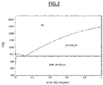
- Pure aluminum, or even eutectic aluminum containing 12 % silicon, could be used, but it has the drawback of its low melting point and of the fact that it very quickly loses its mechanical characteristics as the temperature increases. Its use, therefore, is not recommendable since it would lose these characteristics even before the solidification point, and that is the reason producers using composite electrodes exclusively use the graphite center/central column of the patents defined in the preceding section. In contrast, as can be seen in the diagram (
Figure 2 ) of Al-Si phases, as the percentage of silicon increases, the melting temperature increases significantly until reaching 100 % silicon, which would be 1402 °C. - Tests have been performed in which it can be observed that hypereutectic Al-Si improve the mechanical characteristics of graphite, with said values being compared in Table 1:
Table 1 Hypereutectic Al-Si alloy Graphite GC 70 %Si-Al RS 55 %Si-Al RS 70 % Si-AI RS 90 %Si-AI HP UHP Nipples Density g/cm3 2.15 2.48 2.41 2.26 1.6 1.7 1.8 Thermal expansion 10-6/°C 6.3 8.7 5.5 4.2 1 0.8 0.35 Thermal conductivity W/m°K 57.2 120.7 112.5 84.3 Tensile strength Mpa 44.3 198.2 143.5 95.6 8 10 25 Modulus of elasticity Gpa 62.7 100.4 75.3 55.2 9 14 Brinell hardness 210 186 268 350 - The hypereutectic Al-Si alloy data is verified by means of laboratory testing in research institutes, scientific publications and manufacturers' catalogues. The graphite data is obtained from manufacturers' catalogues for medium grade HP electrodes; high grade UHP electrodes y nipples (connected electrodes) having special treatment. In the (Table 1) hypereutectic Al-Si alloy data, it can be seen that the form of solidification of the product is fundamental. The product GC has had direct solidification whereby first the silicon solidified and then the aluminum, which created silicon crystals that very significant jeopardize the mechanical characteristics, although in the worst-case scenario it is 4 times greater than graphite. However, the extra rapid form of solidification by spraying the metal by means of gas counterflow, for example, nitrogen and others, and subsequent pressing of the powder at temperatures below 500 °C, very considerably improves said characteristics. Furthermore, the characteristics can be improved by adding in liquid phase certain elements such as Cu and/or graphite and/or others according to known techniques for improving characteristics in the aluminum sector.
- Therefore, the self-baking electrode of the present invention is formed by an outer casing with a smooth wall on the inside and with a metallic concentric inner column, which has not been known until now in this industrial sector. The casing and central column have different sliding rings similarly to the composite electrode described above. Preferably, the central column of the electrode is made of a hypereutectic Al-Si alloy in which the percentage of silicon is between 25 and 80 %, or another aluminum alloy but one which is reinforced and attached by high-strength carbon fiber parts.
- In relation to the configuration of the electrode of the invention, the physical shape of said center or central column and how they are connected to one another is essential, as is developing a solution that favors bonding between the paste and said central column. In all cases, the central column is an element having a length between 2 and 3 meters and a variable diameter, depending on the diameter of the electrode of the furnace, in the same manner in which the diameter of the graphite in the composite electrode is variable.
- There is a first possible configuration which consists of a round solid, similar to the graphite center, which would have the advantage of its lower manufacturing cost and the drawback that the bonding surface between paste and metal is only the surface of the circumference. Said surface could be rough to favor adhesion. However, this configuration has the problem that when it melts, it generates a hollow which can produce areas of brittleness in the electrode assembly.
- For this reason, the present invention discloses a solution which is based on a central column with a plurality of radial fins departing from a hollow tube, whereby allowing the column to be star-shaped. The tube has a central outer diameter between 90 and 350 mm and an inner diameter between 40 and 250 mm sufficient for providing the assembly with mechanical strength, from which assembly there preferably depart between 4 and 10 fins or slightly conical arms with a rounded tip having a much smaller thickness between 5 and 30 mm and lengths between 40 and 380 mm intended for significantly increasing the contact surface between metal and paste. These fins can in turn be perforated so that when the paste is introduced in said perforations, it works under shear, increasing the mechanical strength of the assembly. In the solution of the present invention, to solve the problems of brittleness previously set forth in the first case of the solid cylinder, the central column is in the form of a hollow tube, such that a third material can be introduced in the center which, upon reaction with the metallic tube or the hypereutectic aluminum-silicon tube shortly before it is melted, will delay such melting and maintain the mechanical support of this central column for more time. This filler material consists of a precursor for silicon carbide which is formed by the reaction of silicon with carbon at high temperatures. This precursor may consist of:
- introducing inside the tube silicon powder with a particle size distribution less than 2 mm and graphite powder having the same particle size distribution and with the stoichiometric amounts of the C+Si reaction, CSi finally being obtained. In this solution, the entire column is kept filled up to the upper part of the electrode, to favor the absence of oxygen and the gradual temperature increase. As the metallic center or column melts, the carbon powder reacts with the silicon or metal of the tube, forming carbides which are slightly expansive in terms of volume and fill up the space which was before occupied by the tube and the fins, improving the mechanical strength of the electrode; or
- filling the inside of the tube with a graphite felt wound around a pre-baked carbon electrode. This is a flexible and very porous material which absorbs the silico-aluminous metal by capillarity, such that it expends in a very flexible manner, fills the entire hollow and leaves a silicon carbide alloy inside the graphite felt, which likewise favors the mechanical strength of the electrode. This felt is a material formed by an array of intertwined graphite yarns, so the felt is porous, and when the metal dissolves, this liquid is absorbed by the felt, and the hollow fills and swells, preventing wear or brittle areas of the column in the lower part of the furnace.
- In another embodiment of the present invention, the column can be configured by two different elements, the metallic central tube and the metallic fins as separate elements which can likewise greatly improve the mechanical strength and lower the manufacturing costs of the central column of the composite electrode compared to the current actual graphite electrode. In this case, the central tube has between 3 and 10 notches on its outer surface outer where there enters a projection which fits perfectly in the notch made in the fin at one of its two ends. The other end of the fin has a rounded tip. They are two different parts, both being manufactured for use in the manufacture of silicon metal with mainly silicon alloy in the form of hypereutectic Al-Si or aluminum attached by high-strength carbon fiber.
- These same ideas can be applied to the rest of the ferroalloys, in which the use of iron does not present contamination problems, which normally use a metallic casing with inner fins which is consumed as the electrode slides. The reason is that it is much simpler to connect the metallic central electrode body that it is to weld a casing that is consumed almost every day and requires between 2 to 3 hours of two good welders. The central column prevents the systematic sliding of the casing through the principle of the double sliding system of the composite electrode and is less expensive than the sum of the cost of the casing and its assembly time in the column. Therefore, in another preferred embodiment of the invention, the metallic column can be made of iron. Finally, as mentioned above, in another embodiment of the invention, the metallic column can be made of a combination of aluminum alloy with carbon fiber, wherein the alloy is the support of the carbon fiber structure and allows the slenderness of the column until the temperature increases and melts the metal, and after that time it is the carbon fiber that resists.
- The form of connection between these central bodies of the electrode is by means of strips preferably made of carbon fiber, which are secured to the two bodies by means of screws or rods going from one side to the other side of the central column. The mechanical tensile strength due to the weight of the electrode marks the dimension of the strips and the through holes, which can be two or more in the space between the fins, as seen in the attached drawings. In the event of using the star-shaped monoblock configuration, the strips can be screwed to the arms of the star, so the two upper and lower elements are attached in a very simple and quick manner, as can be seen in subsequent figures. The way the electrode descends inside the furnace is by means of sliding rings, which are generally two in number: a fixed ring and a mobile ring. The electrode is usually supported by both rings, but when sliding is to be done from the standby position the movements are: the fixed ring opens, the closed mobile ring slides or drops down, which pulls the electrode, the fixed ring closes, the mobile ring opens and moves up to the standby position. So successively, the sliding rings are always in the same site of the column, what pulls the mobile ring is the metallic casing inside which is the carbon paste with the corresponding phase change from solid to liquid and back to solid, according to the height.
- It must be taken into account that throughout the description and claims, the term "comprises" and its variants do not seek to exclude other technical features or additional elements. Furthermore, for the purpose of completing the description and helping to better understand the features of the invention, a set of figures and drawings is provided in which the following is depicted in an illustrative and nonlimiting manner:
-
Figure 1 . Diagram of the assembly of a self-baking electrode with a central column in a submerged electric arc furnace. -
Figure 2 . Representation of the diagram of Al-Si phases where it can be observed that as the percentage of silicon increases, the melting temperature increases significantly until reaching 100 % silicon at a temperature of 1402 °C. -
Figure 3 . Perspective view of the internal structure of a way of carrying out the electrode of the present invention to practice. -
Figure 4 . Plan view of the preceding figure. -
Figure 5 . Schematic depiction of a star-shaped electrode column where the core and fins are a monoblock element. -
Figure 6 . Plan view of the preceding figure. - As can be schematically seen in
Figure 1 , the present invention describes a composite self-baking electrode (E), with a distinguished core (1) and serving as mechanical support, having at least one set of sliding rings (2) for said core (1), and a second set of rings (3) for an outer metallic casing (7) without inner fins, which is filled with a carbon paste, and which is represented in its three phases: Initial solid (4), liquid underneath (5) and baked (6). The baking of the paste is performed by the heat communicated from the furnace itself and transmitted by the carbon itself and the central core and mainly through the electric energy which is introduced through the contact plates (9) of the electrode. With this, the paste obtains in plates in the area baked (6) the rigidity and consistency to continue descending only the baked paste in the column until reaching the submerged arc or lower area (8) of the furnace where temperatures around 2500 °C are reached. This figure serves for both the present invention where the column is metallic and for conventional electrodes with a graphite center. - In a first embodiment of the invention, as can be seen in
Figures 3 and4 , the core (1) of the electrode is a central column made up of a hollow tube and a plurality of radial fins, which given the body as a whole a star shape, all of said fins being formed by a metallic material, such as a hypereutectic aluminum-silicon material or iron for other ferroalloys. Specifically, the hollow of the core/center of the tube (10) can be observed, the fins (11) departing and projecting from the tube (10) in a radial manner with a much smaller thickness intended for significantly increasing the contact surface between the metal and the paste (14), the concentric core (1) and paste (14) being externally protected by the casing (7) having the diameter of the electrode which will be introduced in the furnace below. These fins can in turn be perforated or have perforations (110) so that when the paste is introduced in said perforations, it works under shear, increasing the mechanical strength of the assembly. The central column is in the form of a hollow tube or cylinder (10), such that a filler material (15) can be introduced in the central hollow which, upon reaction with hypereutectic aluminum-silicon, or iron, or aluminum with carbon fiber, as the case may be, which when melted, will delay such melting and maintain the mechanical support of this central core (1) for more time. This filler material (15) consists of a precursor, preferably for silicon carbide. In the first embodiment, the hollow cylinder or tube (10) has a plurality of notches (101) in which there is introduced the initial end of each of the fins (11) produced from the same alloy, but in an independent manner. The different cores (1), between 2 and 3 meters in height, are attached by means of pins (13) or through pins at the ends of the column in turn attached by strips (12), all of which are made of high mechanical strength carbon fiber, without having to perform any weld, whereby allowing the creation of an electrode of the required height. - In a second embodiment of the invention, as can be observed in
Figure 5 and6 , the electrode core (1) is a star-shaped column made of a metallic material, for example a hypereutectic Al-Si alloy material, or iron, or aluminum with carbon fiber, as the case may be, all forming a single monoblock body where there is a central part in the form of a hollow cylinder (10) with a central diameter, from which there radially emerge a plurality of fins (11) for significantly increasing the contact surface between metal and paste (14), the core (1) and the paste (14) being externally concentric by the casing (7) having the diameter of the electrode which will be introduced in the furnace below, and in which the connection between the parts by means of high mechanical strength carbon fiber strips.
Claims (13)
- Self-baking electrode for submerged electric arc furnaces comprising a center column, wherein the electrode is of the type formed by and comprising a core, a carbon paste covering it and an outer concentric casing covering the core and the paste and having the diameter of the electrode which is introduced in the furnace; both the casing and the core having different sliding rings for being introduced and lowered into the furnace; wherein the central column is characterized in that the core (1) is made up of a central tube (10) which is hollow and made of a metallic material, and a plurality of fins (11) made of a metallic material which project and depart radially from the tube (10); and wherein a filler material (15) consisting of a precursor for silicon carbide is introduced in the hollow of the tube (10).
- Self-baking electrode for submerged electric arc furnaces comprising a center column according to claim 1, characterized in that the metallic material is a hypereutectic Al-Si alloy.
- Self-baking electrode for submerged electric arc furnaces comprising a center column according to claim 2, characterized in that the percentage of silicon in the hypereutectic Al-Si alloy is comprised between 25 and 80 %.
- Self-baking electrode for submerged electric arc furnaces comprising a center column according to claim 1, characterized in that the metallic material is iron.
- Self-baking electrode for submerged electric arc furnaces comprising a center column according to claim 1, characterized in that the metallic material is the combination of an aluminum alloy with outer attachment strips made of carbon fiber.
- Self-baking electrode for submerged electric arc furnaces comprising a center column according to claim 1, characterized in that the precursor is a silicon powder mixture with a particle size distribution less than 2 mm and graphite powder having the same particle size distribution.
- Self-baking electrode for submerged electric arc furnaces comprising a center column according to claim 1, characterized in that the precursor is a graphite felt wound around a pre-baked carbon electrode and consisting of a weave of intertwined graphite yarns.
- Self-baking electrode for submerged electric arc furnaces comprising a center column according to claim 1, characterized in that the number of fins (11) departing and projecting radially from the tube (10) is comprised between 4 and 10.
- Self-baking electrode for submerged electric arc furnaces comprising a center column according to claim 1, characterized in that the fins (11) have perforations (110).
- Self-baking electrode for submerged electric arc furnaces comprising a center column according to claim 1, characterized in that the different cores (1) are attached by means of pins (13) at the ends of the center in turn attached by high-strength carbon fiber strips (12).
- Self-baking electrode for submerged electric arc furnaces comprising a center column according to any of the preceding claims, characterized in that the central hollow tube (10) and the plurality of fins (11) are separate and are connected by means of introducing the initial end of each of the fins (11) into notches (101) made for that purpose on the surface of the hollow tube (10).
- Self-baking electrode for submerged electric arc furnaces comprising a center column according to claim 11, characterized in that the tube (10) has a central outer diameter between 90 and 350 mm and an inner diameter between 40 and 250 mm; and the fins (11) having a conical configuration with a rounded tip, wherein the thickness is comprised between 5 and 30 mm and it has lengths between 40 and 380 mm.
- Self-baking electrode for submerged electric arc furnaces comprising a center column according to any of claims 1 to 10, characterized in that the tube (10) and the plurality of fins (11) form a monoblock body.
Applications Claiming Priority (2)
| Application Number | Priority Date | Filing Date | Title |
|---|---|---|---|
| ES201830212A ES2724498B2 (en) | 2018-03-05 | 2018-03-05 | CENTRAL COLUMN FOR SELF-COOKING ELECTRODES IN SUBMERGED ARC OVEN OVENS |
| PCT/ES2019/070111 WO2019170941A1 (en) | 2018-03-05 | 2019-02-27 | Self-baking electrode for submerged electric arc furnaces comprising a center column |
Publications (1)
| Publication Number | Publication Date |
|---|---|
| EP3764742A1 true EP3764742A1 (en) | 2021-01-13 |
Family
ID=66182604
Family Applications (1)
| Application Number | Title | Priority Date | Filing Date |
|---|---|---|---|
| EP19717961.7A Withdrawn EP3764742A1 (en) | 2018-03-05 | 2019-02-27 | Self-baking electrode for submerged electric arc furnaces comprising a center column |
Country Status (3)
| Country | Link |
|---|---|
| EP (1) | EP3764742A1 (en) |
| ES (1) | ES2724498B2 (en) |
| WO (1) | WO2019170941A1 (en) |
Cited By (1)
| Publication number | Priority date | Publication date | Assignee | Title |
|---|---|---|---|---|
| EP4601414A4 (en) * | 2022-10-07 | 2026-01-28 | Posco Co Ltd | COMPOSITION FOR ELECTRODE ROD, ELECTRODE ROD, METHOD FOR PRODUCE AN ELECTRODE ROD AND METHOD FOR PRODUCE MOLTENED METAL |
Family Cites Families (5)
| Publication number | Priority date | Publication date | Assignee | Title |
|---|---|---|---|---|
| DE1440564B2 (en) * | 1959-04-11 | 1972-02-17 | Societe Edison-Settore Chimico S.p.A.-Azienda Industriale San Marco, Mailand (Italien) | ELECTRIC ARC OR REDUCING FURNACE |
| US3524004A (en) * | 1968-12-03 | 1970-08-11 | Ohio Ferro Alloys Corp | Non-metal reinforced self-baking electrode for electric furnaces |
| US4756813A (en) * | 1986-10-24 | 1988-07-12 | Stanley Earl K | Self-baking electrode |
| DE4010353A1 (en) * | 1990-03-28 | 1991-10-02 | Mannesmann Ag | Operating metallurgical furnace with self-baking electrode - lockable traction rod within electrode |
| CN201904937U (en) * | 2010-12-24 | 2011-07-20 | 登封电厂集团铝合金有限公司 | Combined electrode self-baking device capable of unshelling for large submerged arc furnace |
-
2018
- 2018-03-05 ES ES201830212A patent/ES2724498B2/en not_active Expired - Fee Related
-
2019
- 2019-02-27 EP EP19717961.7A patent/EP3764742A1/en not_active Withdrawn
- 2019-02-27 WO PCT/ES2019/070111 patent/WO2019170941A1/en not_active Ceased
Cited By (1)
| Publication number | Priority date | Publication date | Assignee | Title |
|---|---|---|---|---|
| EP4601414A4 (en) * | 2022-10-07 | 2026-01-28 | Posco Co Ltd | COMPOSITION FOR ELECTRODE ROD, ELECTRODE ROD, METHOD FOR PRODUCE AN ELECTRODE ROD AND METHOD FOR PRODUCE MOLTENED METAL |
Also Published As
| Publication number | Publication date |
|---|---|
| WO2019170941A1 (en) | 2019-09-12 |
| ES2724498B2 (en) | 2020-01-17 |
| ES2724498A1 (en) | 2019-09-11 |
Similar Documents
| Publication | Publication Date | Title |
|---|---|---|
| EP2327118B1 (en) | Seal ring and associated method | |
| JPS6026260B2 (en) | Structure for rotating anode X-ray tube | |
| JPH0233111B2 (en) | ||
| JPH033557B2 (en) | ||
| KR20100019520A (en) | Glass microfluidic devices and methods of manufacture thereof | |
| EP3764742A1 (en) | Self-baking electrode for submerged electric arc furnaces comprising a center column | |
| JPH08506315A (en) | High heat resistant structural parts | |
| US3036017A (en) | Heat resistant and oxidation proof materials | |
| KR20000065253A (en) | Vacuum insulated container and its manufacturing method | |
| JPS6010414B2 (en) | Anodic target bonding method | |
| JPS6258105B2 (en) | ||
| USRE31568E (en) | Composite substrate for rotating x-ray anode tube | |
| JPH0784352B2 (en) | Method of manufacturing functionally graded material | |
| CN102143926B (en) | Utilize the method for infusibility soldering assemble carbon parts | |
| JP6457397B2 (en) | Side wall bricks for electrolytic cell walls for reducing aluminum | |
| US2578167A (en) | Grinding wheel and method of producing same | |
| JPS5857247A (en) | Rotary anode for x-ray tube and its manufacture | |
| JPS5816795A (en) | Brazing material | |
| JP2016505714A5 (en) | ||
| EP0917181A1 (en) | High pressure discharge lamp and method of manufacturing the same | |
| KR100925015B1 (en) | Magnetron cathode structure fusion body and manufacturing method | |
| JPH06102803B2 (en) | Method of manufacturing functionally graded material | |
| WO2005007589A1 (en) | Tank for melting solder glass | |
| CN103710728A (en) | Method for connecting ceramic alloy outer shell and metal inner core for metal molten salt electrolysis | |
| Devine Jr | A composite substrate for rotating X-ray anode tube |
Legal Events
| Date | Code | Title | Description |
|---|---|---|---|
| STAA | Information on the status of an ep patent application or granted ep patent |
Free format text: STATUS: UNKNOWN |
|
| STAA | Information on the status of an ep patent application or granted ep patent |
Free format text: STATUS: THE INTERNATIONAL PUBLICATION HAS BEEN MADE |
|
| PUAI | Public reference made under article 153(3) epc to a published international application that has entered the european phase |
Free format text: ORIGINAL CODE: 0009012 |
|
| STAA | Information on the status of an ep patent application or granted ep patent |
Free format text: STATUS: REQUEST FOR EXAMINATION WAS MADE |
|
| 17P | Request for examination filed |
Effective date: 20200820 |
|
| AK | Designated contracting states |
Kind code of ref document: A1 Designated state(s): AL AT BE BG CH CY CZ DE DK EE ES FI FR GB GR HR HU IE IS IT LI LT LU LV MC MK MT NL NO PL PT RO RS SE SI SK SM TR |
|
| AX | Request for extension of the european patent |
Extension state: BA ME |
|
| DAV | Request for validation of the european patent (deleted) | ||
| DAX | Request for extension of the european patent (deleted) | ||
| STAA | Information on the status of an ep patent application or granted ep patent |
Free format text: STATUS: THE APPLICATION IS DEEMED TO BE WITHDRAWN |
|
| 18D | Application deemed to be withdrawn |
Effective date: 20230901 |