EP3764729A1 - Wireless communication system, slave wireless device and master wireless device - Google Patents
Wireless communication system, slave wireless device and master wireless device Download PDFInfo
- Publication number
- EP3764729A1 EP3764729A1 EP19764648.2A EP19764648A EP3764729A1 EP 3764729 A1 EP3764729 A1 EP 3764729A1 EP 19764648 A EP19764648 A EP 19764648A EP 3764729 A1 EP3764729 A1 EP 3764729A1
- Authority
- EP
- European Patent Office
- Prior art keywords
- slave
- master
- wireless device
- wireless
- control unit
- Prior art date
- Legal status (The legal status is an assumption and is not a legal conclusion. Google has not performed a legal analysis and makes no representation as to the accuracy of the status listed.)
- Granted
Links
Images



Classifications
-
- G—PHYSICS
- G05—CONTROLLING; REGULATING
- G05B—CONTROL OR REGULATING SYSTEMS IN GENERAL; FUNCTIONAL ELEMENTS OF SUCH SYSTEMS; MONITORING OR TESTING ARRANGEMENTS FOR SUCH SYSTEMS OR ELEMENTS
- G05B19/00—Program-control systems
- G05B19/02—Program-control systems electric
- G05B19/04—Program control other than numerical control, i.e. in sequence controllers or logic controllers
- G05B19/042—Program control other than numerical control, i.e. in sequence controllers or logic controllers using digital processors
- G05B19/0421—Multiprocessor system
-
- H—ELECTRICITY
- H04—ELECTRIC COMMUNICATION TECHNIQUE
- H04W—WIRELESS COMMUNICATION NETWORKS
- H04W4/00—Services specially adapted for wireless communication networks; Facilities therefor
- H04W4/30—Services specially adapted for particular environments, situations or purposes
- H04W4/33—Services specially adapted for particular environments, situations or purposes for indoor environments, e.g. buildings
-
- H—ELECTRICITY
- H04—ELECTRIC COMMUNICATION TECHNIQUE
- H04W—WIRELESS COMMUNICATION NETWORKS
- H04W64/00—Locating users or terminals or network equipment for network management purposes, e.g. mobility management
-
- H—ELECTRICITY
- H04—ELECTRIC COMMUNICATION TECHNIQUE
- H04W—WIRELESS COMMUNICATION NETWORKS
- H04W76/00—Connection management
- H04W76/10—Connection setup
-
- H—ELECTRICITY
- H04—ELECTRIC COMMUNICATION TECHNIQUE
- H04W—WIRELESS COMMUNICATION NETWORKS
- H04W76/00—Connection management
- H04W76/30—Connection release
-
- G—PHYSICS
- G05—CONTROLLING; REGULATING
- G05B—CONTROL OR REGULATING SYSTEMS IN GENERAL; FUNCTIONAL ELEMENTS OF SUCH SYSTEMS; MONITORING OR TESTING ARRANGEMENTS FOR SUCH SYSTEMS OR ELEMENTS
- G05B2219/00—Program-control systems
- G05B2219/10—Plc systems
- G05B2219/15—Plc structure of the system
- G05B2219/15117—Radio link, wireless
-
- G—PHYSICS
- G05—CONTROLLING; REGULATING
- G05B—CONTROL OR REGULATING SYSTEMS IN GENERAL; FUNCTIONAL ELEMENTS OF SUCH SYSTEMS; MONITORING OR TESTING ARRANGEMENTS FOR SUCH SYSTEMS OR ELEMENTS
- G05B2219/00—Program-control systems
- G05B2219/20—Pc systems
- G05B2219/22—Pc multi processor system
- G05B2219/2231—Leader-follower
-
- H—ELECTRICITY
- H04—ELECTRIC COMMUNICATION TECHNIQUE
- H04W—WIRELESS COMMUNICATION NETWORKS
- H04W76/00—Connection management
- H04W76/30—Connection release
- H04W76/34—Selective release of ongoing connections
-
- H—ELECTRICITY
- H04—ELECTRIC COMMUNICATION TECHNIQUE
- H04W—WIRELESS COMMUNICATION NETWORKS
- H04W84/00—Network topologies
- H04W84/18—Self-organising networks, e.g. ad-hoc networks or sensor networks
- H04W84/20—Leader-follower arrangements
Definitions
- the present invention relates to: a wireless communication system including a master wireless device and a plurality of slave wireless devices, the plurality of slave wireless devices being provided to a certain appliance and being capable of wireless communication with the master wireless device; the slave wireless device capable of wireless communication with the master wireless device; and the master wireless device capable of wireless communication with the plurality of slave wireless devices.
- Japanese Laid-Open Patent Publication No. 2017-188868 discloses a wireless communication system that, by a plurality of slave wireless devices being provided to a plurality of appliances disposed in a communication range of a master wireless device, is capable of wireless communication between the master wireless device and the plurality of slave wireless devices.
- a configuration is adopted such that a specific master wireless device and the plurality of slave wireless devices are wirelessly connected. Therefore, if, due to movement of the appliance, the slave wireless device deviates from the communication range of the master wireless device, it becomes impossible to perform wireless communication between the specific master wireless device and the slave wireless device that has deviated from the communication range. Moreover, even if this slave wireless device enters the communication range of another master wireless device, the slave wireless device that has entered the communication range and the other master wireless device cannot be wirelessly connected.
- the present invention which has been made considering such a problem, has an object of providing a wireless communication system, a slave wireless device, and a master wireless device that enable wireless communication to be performed between the slave wireless device and the master wireless device even when an appliance moves.
- a wireless communication system is a wireless communication system including: a master wireless device; and a plurality of slave wireless devices that are provided to a plurality of appliances and are capable of wireless communication with the master wireless device.
- the plurality of appliances are movable.
- a plurality of the master wireless devices each include a master control unit and a master communication unit.
- the plurality of slave wireless devices each include a slave control unit and a slave communication unit.
- the master control unit of the master wireless device wirelessly connected to the slave wireless device transmits to the slave communication unit of the slave wireless device via the master communication unit a cut-off request signal for requesting cut-off of a wireless connection, with respect to the slave wireless device deviating from a predetermined communication-target region of the master wireless device.
- the slave control unit of the slave wireless device cuts off the wireless connection in the case that the slave communication unit has received the cut-off request signal.
- the slave wireless device deviating from the communication-target region attains a connection-free state.
- the slave wireless device and the other master wireless device it becomes possible, in the case where the slave wireless device has entered the communication-target region of another master wireless device, for the slave wireless device and the other master wireless device to be wirelessly connected.
- the master control unit transmits to the slave communication unit of the slave wireless device via the master communication unit a connection request signal for requesting the wireless connection, with respect to the slave wireless device that has entered the communication-target region.
- the slave control unit of the slave wireless device performs the wireless connection in the case that the slave communication unit has received the connection request signal.
- the slave control unit is capable of transmitting to the master communication unit via the slave communication unit a connection completion signal to the effect that the wireless connection has been completed and a reception completion signal to the effect that the cut-off request signal has been received.
- the master control unit can recognize cut-off of the wireless connection to have been performed in the case that the reception completion signal is received, or that, for a fixed time, there is no response to the master communication unit from the slave communication unit.
- one bank may be configured by a plurality of the slave wireless devices provided to a plurality of the appliances.
- each of a plurality of the slave wireless devices further includes a slave-side table storing at least an identification number of the bank to which the slave wireless device itself belongs, and identification numbers of a plurality of the master wireless devices.
- each of a plurality of the master wireless devices further includes a master-side table storing at least identification numbers of a plurality of the banks, and an identification number of the master wireless device itself.
- the master control unit transmits to the slave communication units of a plurality of the slave wireless devices belonging to one of the banks that has entered the communication-target region, via the master communication unit, the connection request signal including the identification number of the one of the banks and the identification number of the master control unit itself, referring to the master-side table.
- the slave control unit may perform the wireless connection in the case that the identification number of the one of the banks included in the connection request signal that has been received by the slave communication unit and the identification number of the bank to which the slave control unit itself belongs match, and that the identification number of the master wireless device included in the connection request signal is stored in the slave-side table, referring to the slave-side table.
- pairing of each of a plurality of the master wireless devices and one of the banks is performed using data files like the master-side table and the slave-side table.
- the wireless connection can be performed accurately and efficiently.
- the identification numbers stored in the slave-side table are each transmitted to the new master wireless device from a plurality of the slave wireless devices configuring the one of the banks, then the identification signals can each be copied to the master-side table of the new master wireless device.
- repair work of the wireless communication system becomes easy.
- the wireless communication system may further include a computer connected to a plurality of the master wireless devices.
- the computer outputs an instruction signal instructing the wireless connection or cut-off of the wireless connection with one of the slave wireless devices, to a plurality of the master wireless devices.
- the master control unit transmits to the slave communication unit via the master communication unit the connection request signal or the cut-off request signal, in the case that the instruction signal has been inputted from the computer.
- the master control unit may output to the computer a completion notification signal for notifying completion of the wireless connection or completion of cut-off of the wireless connection, in the case that a connection completion signal to the effect that the wireless connection has been completed, or a reception completion signal to the effect that the cut-off request signal has been received is received by the master communication unit via the slave communication unit from the slave control unit, or that, for a fixed time, there is no response to the master communication unit from the slave communication unit.
- the computer can easily confirm completion of the wireless connection or completion of cut-off of the wireless connection, based on the completion notification signal that has been inputted.
- a slave wireless device is a slave wireless device provided to a certain appliance and capable of wireless communication with a master wireless device, wherein the appliance is movable.
- the slave wireless device includes a slave control unit and a slave communication unit. The slave control unit cuts off a wireless connection with the master wireless device in the case that the slave communication unit has received a cut-off request signal from the master wireless device.
- the slave wireless device attains the connection-free state.
- the slave wireless device has deviated from the communication-target region of the master wireless device to enter the communication-target region of another master wireless device, for the slave wireless device to be wirelessly connected to the other master wireless device.
- the present invention it becomes possible for wireless communication to be performed between the slave wireless device and the other master wireless device even when the appliance moves.
- the slave control unit may perform the wireless connection in the case that the slave communication unit has received the connection request signal from the master wireless device.
- the slave wireless device in the connection-free state and the master wireless device can be easily wirelessly connected.
- a master wireless device is a master wireless device capable of wireless communication with a plurality of slave wireless devices that are provided to a plurality of appliances, wherein a plurality of the appliances are movable.
- the master wireless device includes a master control unit and a master communication unit.
- the master control unit transmits to the slave wireless device via the master communication unit a cut-off request signal for requesting the slave wireless device to cut-off a wireless connection.
- the slave wireless device cuts off the wireless connection, and attains the connection-free state.
- the slave wireless device it becomes possible, in the case where the slave wireless device has deviated from the communication-target region to enter the communication-target region of another master wireless device, for the slave wireless device to be wirelessly connected to the other master wireless device.
- the present invention it becomes possible for wireless communication to be performed between the slave wireless device and the other master wireless device even when the appliance moves.
- the master control unit may transmit to the slave wireless device via the master communication unit a connection request signal for requesting the wireless connection.
- the slave wireless device in the connection-free state and the master wireless device can be easily wirelessly connected.
- a wireless communication system 10 includes: a plurality of master wireless devices 12; a plurality of slave wireless devices 16 provided to a plurality of appliances 14, the plurality of slave wireless devices 16 configuring a later-mentioned plurality of banks 32 and being capable of wireless communication between themselves and one master wireless device 12; and a computer 18 connected to the plurality of master wireless devices 12.
- the number of the plurality of stations 22 and the plurality of master wireless devices 12 is assumed to be L (where L is an integer of 1 or more).
- the master wireless device 12 has a certain communication range, a region within the station 22 where the master wireless device 12 is installed, of this communication range is set to a communication-target region 24 for performing wireless communication between the master wireless device 12 and the plurality of slave wireless devices 16 configuring one bank 32.
- communication-target regions 24 never overlap.
- the plurality of carriages 28 each being an appliance for movement on which an automobile 26 (refer to FIG. 2 ) prior to completion is placed, are conveyed sequentially along the conveying direction.
- a periphery of the automobile 26 has disposed therein a plurality of the appliances 14 of the likes of a clamp cylinder for clamping an automobile component, such as a door of the automobile 26.
- Each of the plurality of appliances 14 is provided with the slave wireless device 16 and various kinds of sensors 30 for detecting a state of the appliance 14 being a measurement target.
- one carriage 28 is provided with a plurality of the appliances 14, a plurality of the slave wireless devices 16, and a plurality of the sensors 30.
- the plurality of appliances 14, the plurality of slave wireless devices 16, and the plurality of sensors 30 move integrally with the carriage 28.
- FIG. 1 illustrates a situation of the banks 32 moving along the conveying direction.
- the bank 32 provided to the carriage 28 enters the communication-target region 24 of the master wireless device 12 disposed in said station 22.
- wireless communication is performed between the master wireless device 12 and the plurality of slave wireless devices 16 configuring the bank 32.
- wireless communication is performed by a frequency hopping system, between one master wireless device 12 and a plurality of slave wireless devices 16. That is, in the master wireless device 12, in order that, after cut-off of the wireless connection, wireless communication can be performed between the master wireless device 12 and the plurality of slave wireless devices 16 of the next bank 32, the master wireless device 12 is switched to a channel of a synchronizing frequency differing from a synchronizing frequency of the bank 32 that has deviated from the communication-target region 24.
- the plurality of slave wireless devices 16 are switched to a channel of a synchronizing frequency differing from the synchronizing frequency in the previous wireless connection. Switching of channels by the frequency hopping system is disclosed in the above-described publication, so a detailed description thereof will be omitted.
- the number of the plurality of slave wireless devices 16 configuring one bank 32 is assumed to be M (where M is an integer of 1 or more). Moreover, in the present embodiment, the number of banks 32 (the number of carriages 28) is assumed to be N.
- FIG. 3 is a block diagram showing, with respect to one station 22, a connection relationship of: the computer 18; the master wireless device 12; and the plurality of slave wireless devices 16 configuring the bank 32.
- the plurality of slave wireless devices 16 configuring the bank 32 have the same configurations as each other.
- the master wireless devices 12 disposed in each of the plurality of stations 22 have the same configurations as each other.
- the computer 18 having bank IDs being identification numbers of a plurality of the banks 32, it is possible for the computer 18 to recognize a current position of each of the banks 32 or a state of the wireless connection with each of the banks 32 (the plurality of slave wireless devices 16) and the master wireless device 12, based on response content inputted from the master wireless device 12.
- the master wireless device 12 includes a master control unit 12a, a master communication unit 12b, and a master-side table 12c.
- the master control unit 12a controls the whole of the master wireless device 12, and performs transmission/reception of signals by wireless communication, between the master wireless device 12 and the slave wireless device 16 in the communication-target region 24 of the master wireless device 12, via the master communication unit 12b.
- the master control unit 12a transmits to the slave wireless device 16 in the communication-target region 24 via the master communication unit 12b a connection request signal for requesting the wireless connection or a cut-off request signal for requesting cut-off of the wireless connection, based on the instruction signal inputted from the computer 18. Furthermore, the master control unit 12a outputs to the computer 18 the completion notification signal for notifying completion of the wireless connection or completion of cut-off of the wireless connection, in the case that the master communication unit 12b has received from the slave wireless device 16 a connection completion signal to the effect that the wireless connection has been completed, or a reception completion signal to the effect that the cut-off request signal has been received.
- the master control unit 12a may output to the computer 18 the completion notification signal, in the case that, for a fixed time, there is no response to the master communication unit 12b from the slave wireless device 16, instead of by reception of the reception completion signal.
- the master control unit 12a outputs the completion notification signal, recognizing cut-off of the wireless connection to have been performed, in the case that the master control unit 12a has received the reception completion signal, or in the case that, for a fixed time, there is no response to the master control unit 12a from the slave wireless device 16.
- the slave wireless device 16 includes a slave control unit 16a, a slave communication unit 16b, and a slave-side table 16c.
- the slave control unit 16a controls the whole of the slave wireless device 16, and performs transmission/reception of signals by wireless communication, between the slave wireless device 16 and the master wireless device 12, via the slave communication unit 16b.
- the slave control unit 16a supplies the appliance 14 with the control instruction signal from the master wireless device 12 received by the slave communication unit 16b, thereby operating the appliance 14, and, at the same time, transmits to the master wireless device 12 via the slave communication unit 16b a detection signal indicating a state of the appliance 14 detected by the sensor 30.
- the master-side table 12c has stored therein: a master ID being an identification number of the master-side table 12c itself; bank IDs being identification numbers of a plurality of the banks 32; and slave IDs being identification numbers of the pluralities of slave wireless devices 16 configuring the plurality of banks 32.
- a master ID of "MIDI” indicating being the first master wireless device 12, and bank IDs from 0 to N, are stored in the master-side table 12c.
- slave IDs of "SIDij" (where i is an integer from 0 to N, and j is an integer from 1 to M) indicating the pluralities of slave wireless devices 16 configuring the banks 32.
- the bank 32 having a bank ID of "0" is prepared as a spare bank for future expansion.
- the slave-side table 16c has stored therein: the bank ID of the bank 32 to which the slave-side table 16c itself belongs; a slave ID being the identification number of the slave-side table 16c itself; and the master IDs of a plurality of the master wireless devices 12.
- a bank ID of "3" indicating being the third bank 32
- a slave ID of "SID31” indicating being the third bank 32
- master IDs of "MIDk” where k is an integer from 1 to L
- the master control unit 12a transmits to the slave communication unit 16b via the master communication unit 12b the connection request signal including one bank ID, one slave ID, and the master ID of the master control unit 12a itself, referring to the master-side table 12c of FIG. 4 .
- the slave control unit 16a performs the wireless connection if the bank ID included in the connection request signal received by the slave communication unit 16b and the bank ID to which the slave control unit 16a itself belongs match, the slave ID included in the connection request signal and the slave ID of the slave control unit 16a itself match, and the master ID included in the connection request signal is stored in the slave-side table 16c of FIG. 5 , referring to the slave-side table 16c.
- the number of the banks 32 (bank IDs) or the number of the plurality of slave wireless devices 16 within the banks 32 (slave IDs) can be increased/decreased depending on a magnitude of capacity of the master-side table 12c.
- the number of the master wireless devices 12 (master IDs) can be increased/decreased depending on a magnitude of capacity of the slave-side table 16c.
- the computer 18 has the bank IDs, and is capable of monitoring all of the banks 32, based on information inputted from the plurality of master wireless devices 12. Therefore, in step S1, the computer 18 recognizes, with regard to the carriage 28 conveyed to one station 22 (refer to FIGS. 1 and 2 ), that the plurality of slave wireless devices 16 configuring the bank 32 are in the connection-free state and that the master wireless device 12 provided to said station 22 is also in an unconnected state.
- the computer 18 grasps the bank ID of the bank 32 entering the communication-target region 24 of this station 22, and, by the bank 32 entering the communication-target region 24, judges that wireless communication is possible between the master wireless device 12 and the plurality of slave wireless devices 16 configuring the bank 32. Note that in the present embodiment, wireless communication by the frequency hopping system is performed, so the master wireless device 12, and the plurality of slave wireless devices 16 configuring the bank 32 have each undergone switching of their channel of synchronizing frequency in advance.
- step S2 the computer 18 outputs to the master wireless device 12 the instruction signal for instructing request of the wireless connection between the master wireless device 12 and the plurality of slave wireless devices 16 configuring the bank 32.
- the computer 18 outputs to the master wireless device 12 the instruction signal including the bank ID of said bank 32.
- step S4 the master control unit 12a (refer to FIG. 3 ) of the master wireless device 12 recognizes the bank ID indicated by the instruction signal.
- the master control unit 12a generates the connection request signal including the bank ID, one slave ID, and the master ID of the master control unit 12a itself, referring to the master-side table 12c, and transmits the generated connection request signal to the communication-target region 24 via the master communication unit 12b.
- step S5 the slave communication units 16b of the plurality of slave wireless devices 16 belonging to the bank 32 receive the connection request signal from the master communication unit 12b.
- step S6 the slave control units 16a of the plurality of slave wireless devices 16 judge, referring to the slave-side table 16c, whether or not the bank ID included in the connection request signal and the bank ID of the bank 32 to which the slave control unit 16a itself belongs match, the slave ID included in the connection request signal and the slave ID of the slave control unit 16a itself match, and the master ID included in the connection request signal is stored in the slave-side table 16c.
- step S7 the slave control unit 16a recognizes the wireless connection to have been requested of the slave wireless device 16 in which the slave control unit 16a itself is included, and performs wireless connection processing between the slave wireless device 16 and the master wireless device 12 indicated by the master ID.
- step S8 the slave control unit 16a generates the connection completion signal including the bank ID to which the slave control unit 16a itself belongs, the slave ID of the slave control unit 16a itself, and the master ID of the master wireless device 12 that has transmitted the connection request signal, referring to the slave-side table 16c, and transmits the generated connection completion signal to the master communication unit 12b via the slave communication unit 16b.
- step S6 each of the IDs do not match, then the slave control unit 16a waits until the slave wireless device 16 receives a connection request signal in which the IDs match.
- step S9 if the master communication unit 12b has received the connection completion signal, then the master control unit 12a recognizes the wireless connection between the master wireless device 12 and the slave wireless device 16 indicated by the slave ID to have been completed if the bank ID and the slave ID included in the connection completion signal are stored in the master-side table 12c, and the master ID included in the connection completion signal and the master ID of the master control unit 12a itself match, referring to the master-side table 12c.
- step S10 the master control unit 12a judges whether or not the wireless connection between the master wireless device 12 and all of the slave wireless devices 16 within the bank 32 has been completed. If the wireless connection between the master wireless device 12 and all of the slave wireless devices 16 has not been completed, that is, if the connection completion signal has not been received from all of the slave wireless devices 16 (step S10: NO), then processing returns to step S4, and the connection request signal is retransmitted targeting the slave wireless device 16 from which the connection completion signal has not been received. Thus, processing of steps S4 to S10 is repeatedly performed until the wireless connection between the master wireless device 12 and all of the slave wireless devices 16 within the bank 32 has been completed.
- step S10 if the wireless connection between the master wireless device 12 and all of the slave wireless devices 16 within the bank 32 has been completed (step S10: YES), then in following step S11, the master control unit 12a outputs to the computer 18 the completion notification signal indicating that the wireless connection between the master wireless device 12 and all of the slave wireless devices 16 configuring the bank 32 has been completed.
- step S12 the computer 18 can recognize that the wireless connection between the plurality of slave wireless devices 16 configuring the bank 32 and the master wireless device 12 has been completed, and that a situation enabling wireless communication has been attained, based on input of the completion notification signal.
- step S13 of FIG. 7 the computer 18 outputs to the master wireless device 12 the control instruction signal for instructing control over the appliance 14. If the control instruction signal has been inputted in step S14, then in following step S15, the master control unit 12a transmits the control instruction signal, via the master communication unit 12b, to the slave communication unit 16b provided to the appliance 14 being a control target.
- step S16 If the control instruction signal has been received by the slave communication unit 16b in step S16, then in following step S17, the slave control unit 16a supplies the received control instruction signal to the appliance 14, and thereby operates the appliance 14. At the same time, the sensor 30 detects an operation state of the appliance 14, and outputs a detection signal thereof to the slave wireless device 16. In step S18, the slave control unit 16a transmits the detection signal of the sensor 30 to the master communication unit 12b via the slave communication unit 16b.
- step S19 If the detection signal has been received by the master communication unit 12b in step S19, then in following step S20, the master control unit 12a outputs to the computer 18 the detection signal received by the master communication unit 12b.
- step S21 the computer 18 can recognize the state of the appliance 14 being the control target, based on input of the detection signal.
- step S22 the computer 18 judges whether or not control over all of the appliances 14 disposed in the one carriage 28 should be completed. If control over all of the appliances 14 has not been completed (step S22: NO), then the computer 18 returns to step S13, and performs output of the control instruction signal to the same appliance 14 or another appliance 14. Repeatedly performing processing of steps S13 to S22 in this way makes it possible for the certain work on the automobile 26 placed on the carriage 28 to be done in one station 22.
- step S23 of FIG. 8 the computer 18 outputs to the master wireless device 12 the instruction signal for instructing cut-off of the wireless connection between the master wireless device 12, and the plurality of slave wireless devices 16 configuring the bank 32.
- step S24 If the instruction signal has been inputted in step S24, then in following step S25, the master control unit 12a generates the cut-off request signal, and transmits the generated cut-off request signal to the communication-target region 24 via the master communication unit 12b.
- step S26 the cut-off request signal has been received from the master communication unit 12b by the slave communication unit 16b of the plurality of slave wireless devices 16
- step S27 the slave control unit 16a recognize cut-off of the wireless connection to have been requested of the slave wireless device 16 in which the slave control unit 16a itself is included. Then, the slave control unit 16a generates the reception completion signal to the effect that the cut-off request signal has been received, and transmits the generated reception completion signal to the master communication unit 12b via the slave communication unit 16b. Subsequently, in step S28, the slave control unit 16a performs cut-off of the wireless connection between the slave wireless device 16 and the master wireless device 12.
- step S29 the reception completion signal has been received by the master communication unit 12b
- the master control unit 12a recognizes cut-off processing of the wireless connection to have been performed in the slave wireless device 16 that has transmitted the reception completion signal.
- step S30 the master control unit 12a judges whether or not cut-off processing of the wireless connection between the master wireless device 12 and all of the slave wireless devices 16 within the bank 32 has been able to be recognized, that is, whether or not the reception completion signal has been received from all of the slave wireless devices 16.
- step S30 If cut-off of the wireless connection between the master wireless device 12 and all of the slave wireless devices 16 has not been able to be recognized, that is, if the reception completion signal has not been received from all of the slave wireless devices 16 (step S30: NO), then processing returns to step S25. Then, the master control unit 12a retransmits the cut-off request signal targeting the slave wireless device 16 from which the reception completion signal has not been received. Thus, processing of steps S25 to S30 is repeatedly performed until the reception completion signal is received from all of the slave wireless devices 16 within the bank 32.
- step S30 If the reception completion signal has been received from all of the slave wireless devices 16 within the bank 32, and cut-off of the wireless connection between the master wireless device 12 and all of the slave wireless devices 16 has been able to be recognized by the master control unit 12a (step S30: YES), then in following step S31, the master control unit 12a outputs to the computer 18 the completion notification signal indicating cut-off of the wireless connection between the master wireless device 12 and all of the slave wireless devices 16 configuring the bank 32 to have been completed.
- the master wireless device 12 attains the unconnected state
- the plurality of slave wireless devices 16 attain the connection-free state.
- switching of the channel of synchronizing frequency is performed in each of the master wireless device 12 and the plurality of slave wireless devices 16 that have attained the connection-free state.
- step S33 the computer 18 can recognize that cut-off of the wireless connection between the plurality of slave wireless devices 16 configuring the bank 32 and the master wireless device 12 has been completed, and that the master wireless device 12 and the plurality of slave wireless devices 16 have together attained the unconnected state, based on the completion notification signal. Note that since the certain work on the automobile 26 have been completed, the carriage 28 is conveyed toward the next station 22 on the downstream side, whereby the bank 32 departs from the communication-target region 24 with all of the slave wireless devices 16 in the connection-free state.
- a plurality of automatic guided vehicles (AGVs) 36 each being an appliance for movement on which the automobile 26 prior to completion is placed, may be moved in the conveying direction, instead of the plurality of carriages 28.
- the bank 32 can be configured by the plurality of slave wireless devices 16 disposed in the automatic guided vehicle 36.
- the master communication unit 12b of the master wireless device 12 may transmit the connection request signal including the bank ID and the master ID.
- the connection request signal can be transmitted simultaneously to the plurality of slave wireless devices 16 of the bank 32 that has entered the communication-target region 24 of the master wireless device 12.
- the master-side table 12c and the slave-side table 16c may have stored therein at least the bank ID and the master ID.
- the master communication unit 12b of the master wireless device 12 may transmit the control instruction signal including the bank ID and the master ID, or the bank ID, the master ID, and the slave ID.
- the plurality of slave wireless devices 16 of the bank 32 that has entered the communication-target region 24 can perform ID match processing in step S17 in a manner similar to in step S6 of FIG. 6 , and after having recognized the control instruction signal to be targeting the appliance 14 connected to the slave wireless device 16 itself, supply the control instruction signal to said appliance 14.
- the slave control unit 16a may supplement the detection signal of the sensor 30 with the bank ID, the master ID, and the slave ID, and transmit the supplemented detection signal to the master communication unit 12b via the slave communication unit 16b.
- the master control unit 12a can recognize that the detection signal as a response to the control instruction signal transmitted in step S15 has been able to be received, based on the bank ID, the master ID, and the slave ID that have been received by the master communication unit 12b.
- the master communication unit 12b of the master wireless device 12 may transmit the cut-off request signal including the bank ID and the master ID, or the bank ID, the master ID, and the slave ID.
- the plurality of slave wireless devices 16 of the bank 32 that has entered the communication-target region 24 can perform ID match processing in step S27 in a manner similar to in step S6 of FIG. 6 , and after having recognized the cut-off request signal to be targeting the slave wireless device 16 itself, perform cut-off processing of the wireless connection.
- the master control unit 12a may recognize cut-off of the wireless connection to have been performed by the slave wireless device 16 in the case that, for a fixed time, there is no response to the master communication unit 12b from said slave wireless device 16, instead of by transmission of the reception completion signal in step S27 and reception of the reception completion signal in step S29.
- the master control unit 12a can output the completion notification signal to the computer 18 in step S31.
- the plurality of appliances 14, the carriage 28, and the automatic guided vehicle 36 are movable.
- the master control unit 12a of the master wireless device 12 wirelessly connected to the slave wireless device 16 provided to the appliance 14, the carriage 28, and the automatic guided vehicle 36 transmits the cut-off request signal to the slave communication unit 16b of the slave wireless device 16 via the master communication unit 12b, with respect to the slave wireless device 16 deviating from the communication-target region 24.
- the slave control unit 16a of the slave wireless device 16 cuts off the wireless connection in the case that the slave communication unit 16b has received the cut-off request signal.
- the slave wireless device 16 deviating from the communication-target region 24 attains the connection-free state.
- the slave wireless device 16 has entered the communication-target region 24 of another master wireless device 12, for the slave wireless device 16 and the other master wireless device 12 to be wirelessly connected.
- wireless communication it becomes possible for wireless communication to be performed between the slave wireless device 16 and the other master wireless device 12 even when the appliance 14, the carriage 28, and the automatic guided vehicle 36 move.
- the master control unit 12a transmits the connection request signal to the slave communication unit 16b via the master communication unit 12b, with respect to the slave wireless device 16 that has entered the communication-target region 24.
- the slave control unit 16a performs the wireless connection in the case that the slave communication unit 16b has received the connection request signal.
- the slave wireless device 16 in the connection-free state and the master wireless device 12 can be easily wirelessly connected.
- the slave control unit 16a transmits the connection completion signal and the reception completion signal to the master communication unit 12b via the slave communication unit 16b.
- the master control unit 12a can easily confirm completion of the wireless connection, and can easily recognize cut-off of the wireless connection to have been performed, based on the connection completion signal and the reception completion signal that have been received by the master communication unit 12b.
- the master control unit 12a may recognize cut-off of the wireless connection to have been performed in the case that, for a fixed time, there is no response to the master communication unit 12b from the slave communication unit 16b, instead of by reception of the reception completion signal by the master communication unit 12b.
- cut-off of the wireless connection can be certainly recognized to have been performed, by reception of the reception completion signal. Moreover, it becomes possible, in the case that, for a fixed time, there is no response from the slave communication unit 16b, for it to be inferred on a master control unit 12a side that cut-off of the wireless connection has been performed by the slave wireless device 16, and that there has been a transition to the connection-free state.
- one bank 32 is configured by the plurality of slave wireless devices 16 provided to the plurality of appliances 14, the carriage 28, and the automatic guided vehicle 36.
- Each of the plurality of slave wireless devices 16 further includes the slave-side table 16c storing the bank ID of the bank 32 to which the slave wireless device 16 itself belongs, the master IDs of a plurality of the master wireless devices 12, and the slave ID of the slave wireless device 16 itself.
- each of the plurality of master wireless devices 12 further includes the master-side table 12c storing the bank IDs of a plurality of the banks 32, the master ID of the master wireless device 12 itself, and the slave IDs of the pluralities of slave wireless devices 16 belonging to the plurality of banks 32.
- the master control unit 12a transmits to the slave communication units 16b of the plurality of slave wireless devices 16 belonging to one bank 32 that has entered the communication-target region 24, via the master communication unit 12b, the connection request signal including at least one bank ID and the master ID of the master control unit 12a itself, referring to the master-side table 12c.
- the slave control unit 16a performs the wireless connection in the case that the bank ID included in the connection request signal that has been received by the slave communication unit 16b and the bank ID of the bank 32 to which the slave control unit 16a itself belongs match, and that the master ID included in the connection request signal is stored in the slave-side table 16c, referring to the slave-side table 16c.
- pairing of each of the plurality of master wireless devices 12 and one bank 32 is performed using data files like the master-side table 12c and the slave-side table 16c.
- the wireless connection can be performed accurately and efficiently.
- the IDs stored in the slave-side table 16c are each transmitted to the new master wireless device 12 from the plurality of slave wireless devices 16 configuring one bank 32, then the IDs can each be copied to the master-side table 12c of the new master wireless device 12.
- repair work of the wireless communication system 10 becomes easy.
- the computer 18 outputs the instruction signal to the plurality of master wireless devices 12.
- the master control unit 12a transmits to the slave communication unit 16b via the master communication unit 12b the connection request signal or the cut-off request signal, in the case that the master control unit 12a has been inputted with the instruction signal, and, on the other hand, outputs to the computer 18 the completion notification signal, in the case that the connection completion signal or the reception completion signal has been received by the master communication unit 12b.
- the computer 18 can easily confirm completion of the wireless connection or completion of cut-off of the wireless connection, based on the inputted completion notification signal.
- the master control unit 12a may output the completion notification signal to the computer when, for a fixed time, there is no response to the master communication unit 12b from the slave communication unit 16b, instead of due to reception of the reception completion signal.
- the slave control unit 16a cuts off the wireless connection with the master wireless device 12 in the case that the slave communication unit 16b has received the cut-off request signal from the master wireless device 12.
- the slave wireless device 16 attains the connection-free state.
- the slave control unit 16a performs the wireless connection in the case that the slave communication unit 16b has received the connection request signal from the master wireless device 12.
- the slave wireless device 16 in the connection-free state and the master wireless device 12 can be easily wirelessly connected.
- the master control unit 12a transmits the cut-off request signal to the slave wireless device 16 via the master communication unit 12b.
- the slave wireless device 16 cuts off the wireless connection, and attains the connection-free state.
- the slave wireless device 16 it becomes possible, in the case where the slave wireless device 16 has deviated from the communication-target region 24 to enter the communication-target region 24 of another master wireless device 12, for the slave wireless device 16 to be wirelessly connected to the other master wireless device 12.
- the master control unit 12a transmits to the slave wireless device 16 via the master communication unit 12b the connection request signal with respect to the slave wireless device 16 that has entered the communication-target region 24, the slave wireless device 16 in the connection-free state and the master wireless device 12 can be easily wirelessly connected.
Landscapes
- Engineering & Computer Science (AREA)
- Computer Networks & Wireless Communication (AREA)
- Signal Processing (AREA)
- Physics & Mathematics (AREA)
- General Physics & Mathematics (AREA)
- Automation & Control Theory (AREA)
- Mobile Radio Communication Systems (AREA)
Abstract
Description
- The present invention relates to: a wireless communication system including a master wireless device and a plurality of slave wireless devices, the plurality of slave wireless devices being provided to a certain appliance and being capable of wireless communication with the master wireless device; the slave wireless device capable of wireless communication with the master wireless device; and the master wireless device capable of wireless communication with the plurality of slave wireless devices.
- Japanese Laid-Open Patent Publication No.
2017-188868 - In the above-described publication, a configuration is adopted such that a specific master wireless device and the plurality of slave wireless devices are wirelessly connected. Therefore, if, due to movement of the appliance, the slave wireless device deviates from the communication range of the master wireless device, it becomes impossible to perform wireless communication between the specific master wireless device and the slave wireless device that has deviated from the communication range. Moreover, even if this slave wireless device enters the communication range of another master wireless device, the slave wireless device that has entered the communication range and the other master wireless device cannot be wirelessly connected.
- The present invention, which has been made considering such a problem, has an object of providing a wireless communication system, a slave wireless device, and a master wireless device that enable wireless communication to be performed between the slave wireless device and the master wireless device even when an appliance moves.
- A wireless communication system according to the present invention is a wireless communication system including: a master wireless device; and a plurality of slave wireless devices that are provided to a plurality of appliances and are capable of wireless communication with the master wireless device. The plurality of appliances are movable. A plurality of the master wireless devices each include a master control unit and a master communication unit. The plurality of slave wireless devices each include a slave control unit and a slave communication unit. In this case, the master control unit of the master wireless device wirelessly connected to the slave wireless device transmits to the slave communication unit of the slave wireless device via the master communication unit a cut-off request signal for requesting cut-off of a wireless connection, with respect to the slave wireless device deviating from a predetermined communication-target region of the master wireless device. Moreover, the slave control unit of the slave wireless device cuts off the wireless connection in the case that the slave communication unit has received the cut-off request signal.
- Thus, the slave wireless device deviating from the communication-target region attains a connection-free state. As a result, it becomes possible, in the case where the slave wireless device has entered the communication-target region of another master wireless device, for the slave wireless device and the other master wireless device to be wirelessly connected. Hence, in the present invention, it becomes possible for wireless communication to be performed between the slave wireless device and the other master wireless device even when the appliance moves.
- Moreover, the master control unit transmits to the slave communication unit of the slave wireless device via the master communication unit a connection request signal for requesting the wireless connection, with respect to the slave wireless device that has entered the communication-target region. The slave control unit of the slave wireless device performs the wireless connection in the case that the slave communication unit has received the connection request signal. As a result, the slave wireless device in the connection-free state and the master wireless device can be easily wirelessly connected.
- Furthermore, the slave control unit is capable of transmitting to the master communication unit via the slave communication unit a connection completion signal to the effect that the wireless connection has been completed and a reception completion signal to the effect that the cut-off request signal has been received. The master control unit can recognize cut-off of the wireless connection to have been performed in the case that the reception completion signal is received, or that, for a fixed time, there is no response to the master communication unit from the slave communication unit.
- Further still, one bank may be configured by a plurality of the slave wireless devices provided to a plurality of the appliances. In this case, each of a plurality of the slave wireless devices further includes a slave-side table storing at least an identification number of the bank to which the slave wireless device itself belongs, and identification numbers of a plurality of the master wireless devices. In addition, each of a plurality of the master wireless devices further includes a master-side table storing at least identification numbers of a plurality of the banks, and an identification number of the master wireless device itself. Moreover, the master control unit transmits to the slave communication units of a plurality of the slave wireless devices belonging to one of the banks that has entered the communication-target region, via the master communication unit, the connection request signal including the identification number of the one of the banks and the identification number of the master control unit itself, referring to the master-side table. In response to this, the slave control unit may perform the wireless connection in the case that the identification number of the one of the banks included in the connection request signal that has been received by the slave communication unit and the identification number of the bank to which the slave control unit itself belongs match, and that the identification number of the master wireless device included in the connection request signal is stored in the slave-side table, referring to the slave-side table.
- Thus, pairing of each of a plurality of the master wireless devices and one of the banks is performed using data files like the master-side table and the slave-side table. As a result, the wireless connection can be performed accurately and efficiently. Moreover, if, at a time of replacing the master wireless device that has broken down with a new master wireless device, the identification numbers stored in the slave-side table are each transmitted to the new master wireless device from a plurality of the slave wireless devices configuring the one of the banks, then the identification signals can each be copied to the master-side table of the new master wireless device. Thus, repair work of the wireless communication system becomes easy.
- Moreover, the wireless communication system may further include a computer connected to a plurality of the master wireless devices. In this case, the computer outputs an instruction signal instructing the wireless connection or cut-off of the wireless connection with one of the slave wireless devices, to a plurality of the master wireless devices. The master control unit transmits to the slave communication unit via the master communication unit the connection request signal or the cut-off request signal, in the case that the instruction signal has been inputted from the computer. Moreover, the master control unit may output to the computer a completion notification signal for notifying completion of the wireless connection or completion of cut-off of the wireless connection, in the case that a connection completion signal to the effect that the wireless connection has been completed, or a reception completion signal to the effect that the cut-off request signal has been received is received by the master communication unit via the slave communication unit from the slave control unit, or that, for a fixed time, there is no response to the master communication unit from the slave communication unit.
- As a result, the computer can easily confirm completion of the wireless connection or completion of cut-off of the wireless connection, based on the completion notification signal that has been inputted.
- Moreover, a slave wireless device according to the present invention is a slave wireless device provided to a certain appliance and capable of wireless communication with a master wireless device, wherein the appliance is movable. In this case, the slave wireless device includes a slave control unit and a slave communication unit. The slave control unit cuts off a wireless connection with the master wireless device in the case that the slave communication unit has received a cut-off request signal from the master wireless device.
- Thus, the slave wireless device attains the connection-free state. As a result, it becomes possible, in the case where the slave wireless device has deviated from the communication-target region of the master wireless device to enter the communication-target region of another master wireless device, for the slave wireless device to be wirelessly connected to the other master wireless device. Hence, in the present invention, it becomes possible for wireless communication to be performed between the slave wireless device and the other master wireless device even when the appliance moves.
- Moreover, the slave control unit may perform the wireless connection in the case that the slave communication unit has received the connection request signal from the master wireless device. As a result, the slave wireless device in the connection-free state and the master wireless device can be easily wirelessly connected.
- Furthermore, a master wireless device according to the present invention is a master wireless device capable of wireless communication with a plurality of slave wireless devices that are provided to a plurality of appliances, wherein a plurality of the appliances are movable. In this case, the master wireless device includes a master control unit and a master communication unit. In the case that the slave wireless device wirelessly connected to the master wireless device deviates from a predetermined communication-target region of the master wireless device, the master control unit transmits to the slave wireless device via the master communication unit a cut-off request signal for requesting the slave wireless device to cut-off a wireless connection.
- Thus, the slave wireless device cuts off the wireless connection, and attains the connection-free state. As a result, it becomes possible, in the case where the slave wireless device has deviated from the communication-target region to enter the communication-target region of another master wireless device, for the slave wireless device to be wirelessly connected to the other master wireless device. Hence, in the present invention, it becomes possible for wireless communication to be performed between the slave wireless device and the other master wireless device even when the appliance moves.
- Moreover, with respect to the slave wireless device that has entered the communication-target region, the master control unit may transmit to the slave wireless device via the master communication unit a connection request signal for requesting the wireless connection. As a result, the slave wireless device in the connection-free state and the master wireless device can be easily wirelessly connected.
-
-
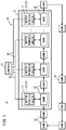
FIG. 1 is a schematic configuration diagram of a wireless communication system according to the present embodiment; -
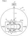
FIG. 2 is an explanatory diagram showing the case where there is one bank in a communication-target region of one master wireless device; -
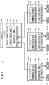
FIG. 3 is a block diagram showing a connection relationship of a computer, the master wireless device, and a plurality of slave wireless devices; -
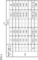
FIG. 4 is a view showing a master-side table ofFIG. 3 ; -
FIG. 5 is a view showing a slave-side table ofFIG. 3 ; -
FIG. 6 is a sequence diagram showing a flow of wireless connection processing with the master wireless device and the slave wireless device; -
FIG. 7 is a sequence diagram showing a flow of control processing over an appliance from the computer; and -
FIG. 8 is a sequence diagram showing a flow of cut-off processing of a wireless connection with the master wireless device and the slave wireless device. - A preferred embodiment of a wireless communication system, a slave wireless device, and a master wireless device according to the present invention will be described in detail below with reference to the accompanying drawings.
- As shown in
FIGS. 1 to 3 , awireless communication system 10 according to the present embodiment includes: a plurality ofmaster wireless devices 12; a plurality ofslave wireless devices 16 provided to a plurality ofappliances 14, the plurality ofslave wireless devices 16 configuring a later-mentioned plurality ofbanks 32 and being capable of wireless communication between themselves and onemaster wireless device 12; and acomputer 18 connected to the plurality ofmaster wireless devices 12. -
FIGS. 1 and2 illustrate an example where thewireless communication system 10 has been applied to wireless communication in an industrial facility. In this example, thewireless communication system 10 is applied to aconveyor line 20 of an automobile production plant. In this case, theconveyor line 20 is provided with a workingarea 21, and this workingarea 21 has provided thereto, sequentially, along a conveying direction of a later-mentioned carriage 28 (a clockwise direction shown inFIG. 1 ), a plurality ofstations 22 for doing certain work. Each of the plurality ofstations 22 has installed therein onemaster wireless device 12, and has installed therein at certain positions an unillustrated plurality of industrial robots for doing certain work. Each of these industrial robots also has connected thereto a wireless device capable of wireless communication with the onemaster wireless device 12. - Note that in the present embodiment, the number of the plurality of
stations 22 and the plurality ofmaster wireless devices 12 is assumed to be L (where L is an integer of 1 or more). Moreover, although themaster wireless device 12 has a certain communication range, a region within thestation 22 where themaster wireless device 12 is installed, of this communication range is set to a communication-target region 24 for performing wireless communication between themaster wireless device 12 and the plurality ofslave wireless devices 16 configuring onebank 32. Hence, even if parts of the communication ranges overlap between themaster wireless devices 12 ofadjacent stations 22, communication-target regions 24 never overlap. - In the
conveyor line 20, the plurality ofcarriages 28 each being an appliance for movement on which an automobile 26 (refer toFIG. 2 ) prior to completion is placed, are conveyed sequentially along the conveying direction. In the plurality ofcarriages 28, a periphery of theautomobile 26 has disposed therein a plurality of theappliances 14 of the likes of a clamp cylinder for clamping an automobile component, such as a door of theautomobile 26. Each of the plurality ofappliances 14 is provided with theslave wireless device 16 and various kinds ofsensors 30 for detecting a state of theappliance 14 being a measurement target. Hence, onecarriage 28 is provided with a plurality of theappliances 14, a plurality of theslave wireless devices 16, and a plurality of thesensors 30. Moreover, by thecarriage 28 being conveyed in the conveying direction, the plurality ofappliances 14, the plurality ofslave wireless devices 16, and the plurality ofsensors 30 move integrally with thecarriage 28. - The plurality of
slave wireless devices 16 disposed in thecarriage 28 configure onebank 32. Therefore, by thecarriage 28 moving, thebank 32 also moves (refer toFIG. 1 ). For convenience of explanation,FIG. 1 illustrates a situation of thebanks 32 moving along the conveying direction. - As shown in
FIGS. 1 and2 , when thecarriage 28 is conveyed to onestation 22 along theconveyor line 20, thebank 32 provided to thecarriage 28 enters the communication-target region 24 of themaster wireless device 12 disposed in saidstation 22. As a result, wireless communication is performed between themaster wireless device 12 and the plurality ofslave wireless devices 16 configuring thebank 32. - Moreover, in said
station 22, when, after certain work has been done on theautomobile 26 placed on thecarriage 28, thecarriage 28 is conveyed from thisstation 22 toward thenext station 22 on a downstream side, it results in thebank 32 deviating from the communication-target region 24. In this case, cut-off processing of a wireless connection is performed between themaster wireless device 12 and the plurality ofslave wireless devices 16 configuring thebank 32. Hence, the plurality ofslave wireless devices 16 after the wireless connection has been cut off attain a connection-free state. - Therefore, in the present embodiment, in each of the plurality of
stations 22, wireless communication is performed between onemaster wireless device 12 and the plurality ofslave wireless devices 16 configuring onebank 32, only when the onebank 32 is in the communication-target region 24 of the onemaster wireless device 12. - Moreover, in the present embodiment too, similarly to in the above-described publication, wireless communication is performed by a frequency hopping system, between one
master wireless device 12 and a plurality ofslave wireless devices 16. That is, in themaster wireless device 12, in order that, after cut-off of the wireless connection, wireless communication can be performed between themaster wireless device 12 and the plurality ofslave wireless devices 16 of thenext bank 32, themaster wireless device 12 is switched to a channel of a synchronizing frequency differing from a synchronizing frequency of thebank 32 that has deviated from the communication-target region 24. On the other hand, in order that wireless communication can be performed between the plurality ofslave wireless devices 16 in the connection-free state and the nextmaster wireless device 12, the plurality ofslave wireless devices 16 are switched to a channel of a synchronizing frequency differing from the synchronizing frequency in the previous wireless connection. Switching of channels by the frequency hopping system is disclosed in the above-described publication, so a detailed description thereof will be omitted. - Note that in the present embodiment, in one
carriage 28, the number of the plurality ofslave wireless devices 16 configuring onebank 32 is assumed to be M (where M is an integer of 1 or more). Moreover, in the present embodiment, the number of banks 32 (the number of carriages 28) is assumed to be N. -
FIG. 3 is a block diagram showing, with respect to onestation 22, a connection relationship of: thecomputer 18; themaster wireless device 12; and the plurality ofslave wireless devices 16 configuring thebank 32. Note that the plurality ofslave wireless devices 16 configuring thebank 32 have the same configurations as each other. Moreover, themaster wireless devices 12 disposed in each of the plurality ofstations 22 have the same configurations as each other. - The
computer 18 and themaster wireless device 12 are connected via acommunication line 34 such as a field bus, and are capable of transmission/reception of signals. Thecomputer 18, which is a PLC (Programmable Logic Controller) or a PC (Personal Computer), for example, performs at least monitoring of the industrial facility (theconveyor line 20 of the automobile production plant). Thecomputer 18 outputs various kinds of instructions (for example, an instruction signal, a control instruction signal) to themaster wireless device 12 via thecommunication line 34. In addition, thecomputer 18 is inputted with various kinds of responses to the instructions (for example, a completion notification signal) from themaster wireless device 12. Furthermore, thecomputer 18 monitors thewireless communication system 10 overall. For example, by thecomputer 18 having bank IDs being identification numbers of a plurality of thebanks 32, it is possible for thecomputer 18 to recognize a current position of each of thebanks 32 or a state of the wireless connection with each of the banks 32 (the plurality of slave wireless devices 16) and themaster wireless device 12, based on response content inputted from themaster wireless device 12. - The
master wireless device 12 includes amaster control unit 12a, amaster communication unit 12b, and a master-side table 12c. Themaster control unit 12a controls the whole of themaster wireless device 12, and performs transmission/reception of signals by wireless communication, between themaster wireless device 12 and theslave wireless device 16 in the communication-target region 24 of themaster wireless device 12, via themaster communication unit 12b. - In addition, the
master control unit 12a transmits to theslave wireless device 16 in the communication-target region 24 via themaster communication unit 12b a connection request signal for requesting the wireless connection or a cut-off request signal for requesting cut-off of the wireless connection, based on the instruction signal inputted from thecomputer 18. Furthermore, themaster control unit 12a outputs to thecomputer 18 the completion notification signal for notifying completion of the wireless connection or completion of cut-off of the wireless connection, in the case that themaster communication unit 12b has received from theslave wireless device 16 a connection completion signal to the effect that the wireless connection has been completed, or a reception completion signal to the effect that the cut-off request signal has been received. Moreover, themaster control unit 12a may output to thecomputer 18 the completion notification signal, in the case that, for a fixed time, there is no response to themaster communication unit 12b from theslave wireless device 16, instead of by reception of the reception completion signal. Thus, themaster control unit 12a outputs the completion notification signal, recognizing cut-off of the wireless connection to have been performed, in the case that themaster control unit 12a has received the reception completion signal, or in the case that, for a fixed time, there is no response to themaster control unit 12a from theslave wireless device 16. - The
slave wireless device 16 includes aslave control unit 16a, aslave communication unit 16b, and a slave-side table 16c. Theslave control unit 16a controls the whole of theslave wireless device 16, and performs transmission/reception of signals by wireless communication, between theslave wireless device 16 and themaster wireless device 12, via theslave communication unit 16b. In this case, theslave control unit 16a supplies theappliance 14 with the control instruction signal from themaster wireless device 12 received by theslave communication unit 16b, thereby operating theappliance 14, and, at the same time, transmits to themaster wireless device 12 via theslave communication unit 16b a detection signal indicating a state of theappliance 14 detected by thesensor 30. - In addition, the
slave control unit 16a transmits the connection completion signal to themaster communication unit 12b via theslave communication unit 16b after having performed the wireless connection with themaster wireless device 12, in the case that theslave communication unit 16b has received the connection request signal. Furthermore, theslave control unit 16a performs cut-off of the wireless connection with themaster wireless device 12 after having transmitted the reception completion signal to themaster communication unit 12b via theslave communication unit 16b, in the case that theslave communication unit 16b has received the cut-off request signal. -
FIG. 4 is a view showing various kinds of identification numbers (IDs) stored in the master-side table 12c, andFIG. 5 is a view showing various kinds of IDs stored in the slave-side table 16c. - The master-side table 12c has stored therein: a master ID being an identification number of the master-side table 12c itself; bank IDs being identification numbers of a plurality of the
banks 32; and slave IDs being identification numbers of the pluralities ofslave wireless devices 16 configuring the plurality ofbanks 32. InFIG. 4 , it is illustrated that a master ID of "MIDI" indicating being the firstmaster wireless device 12, and bank IDs from 0 to N, are stored in the master-side table 12c. Moreover, inFIG. 4 , there are also stored slave IDs of "SIDij" (where i is an integer from 0 to N, and j is an integer from 1 to M) indicating the pluralities ofslave wireless devices 16 configuring thebanks 32. Note that in the present embodiment, at the same time as there being present the plurality ofbanks 32 having bank IDs of "1 to N", thebank 32 having a bank ID of "0" is prepared as a spare bank for future expansion. - The slave-side table 16c has stored therein: the bank ID of the
bank 32 to which the slave-side table 16c itself belongs; a slave ID being the identification number of the slave-side table 16c itself; and the master IDs of a plurality of themaster wireless devices 12. InFIG. 5 , it is illustrated that a bank ID of "3" indicating being thethird bank 32, a slave ID of "SID31", and master IDs of "MIDk" (where k is an integer from 1 to L), are stored in the slave-side table 16c. - Hence, the
master control unit 12a transmits to theslave communication unit 16b via themaster communication unit 12b the connection request signal including one bank ID, one slave ID, and the master ID of themaster control unit 12a itself, referring to the master-side table 12c ofFIG. 4 . Theslave control unit 16a performs the wireless connection if the bank ID included in the connection request signal received by theslave communication unit 16b and the bank ID to which theslave control unit 16a itself belongs match, the slave ID included in the connection request signal and the slave ID of theslave control unit 16a itself match, and the master ID included in the connection request signal is stored in the slave-side table 16c ofFIG. 5 , referring to the slave-side table 16c. - On the other hand, the
slave control unit 16a transmits to themaster communication unit 12b via theslave communication unit 16b the connection completion signal including the bank ID to which theslave control unit 16a itself belongs, the slave ID of theslave control unit 16a itself, and the master ID of themaster wireless device 12 being a wireless connection target, referring to the slave-side table 16c. Themaster control unit 12a recognizes the wireless connection to have been completed if the bank ID and the slave ID included in the connection completion signal received by themaster communication unit 12b are stored in the master-side table 12c, and the master ID included in the connection completion signal and the master ID of themaster control unit 12a itself match, referring to the master-side table 12c. - Therefore, the number of the banks 32 (bank IDs) or the number of the plurality of
slave wireless devices 16 within the banks 32 (slave IDs) can be increased/decreased depending on a magnitude of capacity of the master-side table 12c. Moreover, the number of the master wireless devices 12 (master IDs) can be increased/decreased depending on a magnitude of capacity of the slave-side table 16c. - Operation of the
wireless communication system 10, themaster wireless device 12, and theslave wireless device 16 according to the present embodiment configured as above, will be described with reference to the sequence diagrams ofFIGS. 6 to 8 . In this operation description, description will be made with reference also toFIGS. 1 to 5 , as required. - In this operation description, operation from one
carriage 28 being conveyed to onestation 22 whereby onebank 32 enters the communication-target region 24 of themaster wireless device 12 to thebank 32 departing from the communication-target region 24 due to movement of thecarriage 28, will be described. Note that this operation is performed similarly for all of thestations 22 shown inFIG. 1 . - As previously mentioned, the
computer 18 has the bank IDs, and is capable of monitoring all of thebanks 32, based on information inputted from the plurality ofmaster wireless devices 12. Therefore, in step S1, thecomputer 18 recognizes, with regard to thecarriage 28 conveyed to one station 22 (refer toFIGS. 1 and2 ), that the plurality ofslave wireless devices 16 configuring thebank 32 are in the connection-free state and that themaster wireless device 12 provided to saidstation 22 is also in an unconnected state. In addition, thecomputer 18 grasps the bank ID of thebank 32 entering the communication-target region 24 of thisstation 22, and, by thebank 32 entering the communication-target region 24, judges that wireless communication is possible between themaster wireless device 12 and the plurality ofslave wireless devices 16 configuring thebank 32. Note that in the present embodiment, wireless communication by the frequency hopping system is performed, so themaster wireless device 12, and the plurality ofslave wireless devices 16 configuring thebank 32 have each undergone switching of their channel of synchronizing frequency in advance. - In following step S2, the
computer 18 outputs to themaster wireless device 12 the instruction signal for instructing request of the wireless connection between themaster wireless device 12 and the plurality ofslave wireless devices 16 configuring thebank 32. In this case, thecomputer 18 outputs to themaster wireless device 12 the instruction signal including the bank ID of saidbank 32. - If the instruction signal has been inputted in step S3, then in following step S4, the
master control unit 12a (refer toFIG. 3 ) of themaster wireless device 12 recognizes the bank ID indicated by the instruction signal. Next, themaster control unit 12a generates the connection request signal including the bank ID, one slave ID, and the master ID of themaster control unit 12a itself, referring to the master-side table 12c, and transmits the generated connection request signal to the communication-target region 24 via themaster communication unit 12b. - Now, if the
carriage 28 has been conveyed to thestation 22, and thebank 32 has entered the communication-target region 24, then in step S5, theslave communication units 16b of the plurality ofslave wireless devices 16 belonging to thebank 32 receive the connection request signal from themaster communication unit 12b. - Then, in step S6, the
slave control units 16a of the plurality ofslave wireless devices 16 judge, referring to the slave-side table 16c, whether or not the bank ID included in the connection request signal and the bank ID of thebank 32 to which theslave control unit 16a itself belongs match, the slave ID included in the connection request signal and the slave ID of theslave control unit 16a itself match, and the master ID included in the connection request signal is stored in the slave-side table 16c. - If, as a result, each of the IDs match, then in following step S7, the
slave control unit 16a recognizes the wireless connection to have been requested of theslave wireless device 16 in which theslave control unit 16a itself is included, and performs wireless connection processing between theslave wireless device 16 and themaster wireless device 12 indicated by the master ID. Subsequently, in step S8, theslave control unit 16a generates the connection completion signal including the bank ID to which theslave control unit 16a itself belongs, the slave ID of theslave control unit 16a itself, and the master ID of themaster wireless device 12 that has transmitted the connection request signal, referring to the slave-side table 16c, and transmits the generated connection completion signal to themaster communication unit 12b via theslave communication unit 16b. Note that if, in step S6, each of the IDs do not match, then theslave control unit 16a waits until theslave wireless device 16 receives a connection request signal in which the IDs match. - In step S9, if the
master communication unit 12b has received the connection completion signal, then themaster control unit 12a recognizes the wireless connection between themaster wireless device 12 and theslave wireless device 16 indicated by the slave ID to have been completed if the bank ID and the slave ID included in the connection completion signal are stored in the master-side table 12c, and the master ID included in the connection completion signal and the master ID of themaster control unit 12a itself match, referring to the master-side table 12c. - In following step S10, the
master control unit 12a judges whether or not the wireless connection between themaster wireless device 12 and all of theslave wireless devices 16 within thebank 32 has been completed. If the wireless connection between themaster wireless device 12 and all of theslave wireless devices 16 has not been completed, that is, if the connection completion signal has not been received from all of the slave wireless devices 16 (step S10: NO), then processing returns to step S4, and the connection request signal is retransmitted targeting theslave wireless device 16 from which the connection completion signal has not been received. Thus, processing of steps S4 to S10 is repeatedly performed until the wireless connection between themaster wireless device 12 and all of theslave wireless devices 16 within thebank 32 has been completed. - In step S10, if the wireless connection between the
master wireless device 12 and all of theslave wireless devices 16 within thebank 32 has been completed (step S10: YES), then in following step S11, themaster control unit 12a outputs to thecomputer 18 the completion notification signal indicating that the wireless connection between themaster wireless device 12 and all of theslave wireless devices 16 configuring thebank 32 has been completed. In step S12, thecomputer 18 can recognize that the wireless connection between the plurality ofslave wireless devices 16 configuring thebank 32 and themaster wireless device 12 has been completed, and that a situation enabling wireless communication has been attained, based on input of the completion notification signal. - In step S13 of
FIG. 7 , thecomputer 18 outputs to themaster wireless device 12 the control instruction signal for instructing control over theappliance 14. If the control instruction signal has been inputted in step S14, then in following step S15, themaster control unit 12a transmits the control instruction signal, via themaster communication unit 12b, to theslave communication unit 16b provided to theappliance 14 being a control target. - If the control instruction signal has been received by the
slave communication unit 16b in step S16, then in following step S17, theslave control unit 16a supplies the received control instruction signal to theappliance 14, and thereby operates theappliance 14. At the same time, thesensor 30 detects an operation state of theappliance 14, and outputs a detection signal thereof to theslave wireless device 16. In step S18, theslave control unit 16a transmits the detection signal of thesensor 30 to themaster communication unit 12b via theslave communication unit 16b. - If the detection signal has been received by the
master communication unit 12b in step S19, then in following step S20, themaster control unit 12a outputs to thecomputer 18 the detection signal received by themaster communication unit 12b. In step S21, thecomputer 18 can recognize the state of theappliance 14 being the control target, based on input of the detection signal. - In following step S22, the
computer 18 judges whether or not control over all of theappliances 14 disposed in the onecarriage 28 should be completed. If control over all of theappliances 14 has not been completed (step S22: NO), then thecomputer 18 returns to step S13, and performs output of the control instruction signal to thesame appliance 14 or anotherappliance 14. Repeatedly performing processing of steps S13 to S22 in this way makes it possible for the certain work on theautomobile 26 placed on thecarriage 28 to be done in onestation 22. - Note that in steps S13 to S22, the
computer 18 transmits the control instruction signal to the wireless device of the industrial robot installed in the communication-target region 24 of thestation 22, via themaster wireless device 12. As a result, the industrial robot can do the certain work on theautomobile 26 placed on thecarriage 28, based on the control instruction signal supplied via the wireless device. In this case, themaster wireless device 12 should utilize technology of the above-described publication to perform wireless communication between itself and the wireless device provided to the industrial robot. Moreover, in steps S13 to S22, themaster wireless device 12 may utilize technology of the above-described publication to perform wireless communication between itself and theslave wireless device 16. - If the certain work on the
automobile 26 have been completed, and control over all of theappliances 14 has been completed (step S22 ofFIG. 7 : YES), then in step S23 ofFIG. 8 , thecomputer 18 outputs to themaster wireless device 12 the instruction signal for instructing cut-off of the wireless connection between themaster wireless device 12, and the plurality ofslave wireless devices 16 configuring thebank 32. - If the instruction signal has been inputted in step S24, then in following step S25, the
master control unit 12a generates the cut-off request signal, and transmits the generated cut-off request signal to the communication-target region 24 via themaster communication unit 12b. - If, in step S26, the cut-off request signal has been received from the
master communication unit 12b by theslave communication unit 16b of the plurality ofslave wireless devices 16, then in step S27, theslave control unit 16a recognize cut-off of the wireless connection to have been requested of theslave wireless device 16 in which theslave control unit 16a itself is included. Then, theslave control unit 16a generates the reception completion signal to the effect that the cut-off request signal has been received, and transmits the generated reception completion signal to themaster communication unit 12b via theslave communication unit 16b. Subsequently, in step S28, theslave control unit 16a performs cut-off of the wireless connection between theslave wireless device 16 and themaster wireless device 12. - If, in step S29, the reception completion signal has been received by the
master communication unit 12b, then themaster control unit 12a recognizes cut-off processing of the wireless connection to have been performed in theslave wireless device 16 that has transmitted the reception completion signal. In following step S30, themaster control unit 12a judges whether or not cut-off processing of the wireless connection between themaster wireless device 12 and all of theslave wireless devices 16 within thebank 32 has been able to be recognized, that is, whether or not the reception completion signal has been received from all of theslave wireless devices 16. If cut-off of the wireless connection between themaster wireless device 12 and all of theslave wireless devices 16 has not been able to be recognized, that is, if the reception completion signal has not been received from all of the slave wireless devices 16 (step S30: NO), then processing returns to step S25. Then, themaster control unit 12a retransmits the cut-off request signal targeting theslave wireless device 16 from which the reception completion signal has not been received. Thus, processing of steps S25 to S30 is repeatedly performed until the reception completion signal is received from all of theslave wireless devices 16 within thebank 32. - If the reception completion signal has been received from all of the
slave wireless devices 16 within thebank 32, and cut-off of the wireless connection between themaster wireless device 12 and all of theslave wireless devices 16 has been able to be recognized by themaster control unit 12a (step S30: YES), then in following step S31, themaster control unit 12a outputs to thecomputer 18 the completion notification signal indicating cut-off of the wireless connection between themaster wireless device 12 and all of theslave wireless devices 16 configuring thebank 32 to have been completed. Thus, by the wireless connection between themaster wireless device 12 and the plurality ofslave wireless devices 16 within thebank 32 being cut off, themaster wireless device 12 attains the unconnected state, and the plurality ofslave wireless devices 16 attain the connection-free state. Subsequently, switching of the channel of synchronizing frequency is performed in each of themaster wireless device 12 and the plurality ofslave wireless devices 16 that have attained the connection-free state. - If the completion notification signal has been inputted in step S32, then in following step S33, the
computer 18 can recognize that cut-off of the wireless connection between the plurality ofslave wireless devices 16 configuring thebank 32 and themaster wireless device 12 has been completed, and that themaster wireless device 12 and the plurality ofslave wireless devices 16 have together attained the unconnected state, based on the completion notification signal. Note that since the certain work on theautomobile 26 have been completed, thecarriage 28 is conveyed toward thenext station 22 on the downstream side, whereby thebank 32 departs from the communication-target region 24 with all of theslave wireless devices 16 in the connection-free state. - In the present embodiment, a plurality of automatic guided vehicles (AGVs) 36 each being an appliance for movement on which the
automobile 26 prior to completion is placed, may be moved in the conveying direction, instead of the plurality ofcarriages 28. In this case too, thebank 32 can be configured by the plurality ofslave wireless devices 16 disposed in the automatic guidedvehicle 36. - Moreover, in step S4 of
FIG. 6 , themaster communication unit 12b of themaster wireless device 12 may transmit the connection request signal including the bank ID and the master ID. Thus, the connection request signal can be transmitted simultaneously to the plurality ofslave wireless devices 16 of thebank 32 that has entered the communication-target region 24 of themaster wireless device 12. As a result, it becomes possible for the wireless connection between themaster wireless device 12 and the plurality ofslave wireless devices 16 to be promptly performed. In this case, the master-side table 12c and the slave-side table 16c may have stored therein at least the bank ID and the master ID. - Furthermore, in step S15 of
FIG. 7 , themaster communication unit 12b of themaster wireless device 12 may transmit the control instruction signal including the bank ID and the master ID, or the bank ID, the master ID, and the slave ID. As a result, the plurality ofslave wireless devices 16 of thebank 32 that has entered the communication-target region 24 can perform ID match processing in step S17 in a manner similar to in step S6 ofFIG. 6 , and after having recognized the control instruction signal to be targeting theappliance 14 connected to theslave wireless device 16 itself, supply the control instruction signal to saidappliance 14. - Further still, in step S18 of
FIG. 7 , theslave control unit 16a may supplement the detection signal of thesensor 30 with the bank ID, the master ID, and the slave ID, and transmit the supplemented detection signal to themaster communication unit 12b via theslave communication unit 16b. As a result, themaster control unit 12a can recognize that the detection signal as a response to the control instruction signal transmitted in step S15 has been able to be received, based on the bank ID, the master ID, and the slave ID that have been received by themaster communication unit 12b. - Moreover, in step S25 of
FIG. 8 , themaster communication unit 12b of themaster wireless device 12 may transmit the cut-off request signal including the bank ID and the master ID, or the bank ID, the master ID, and the slave ID. As a result, the plurality ofslave wireless devices 16 of thebank 32 that has entered the communication-target region 24 can perform ID match processing in step S27 in a manner similar to in step S6 ofFIG. 6 , and after having recognized the cut-off request signal to be targeting theslave wireless device 16 itself, perform cut-off processing of the wireless connection. - Furthermore, as shown by the broken lines of
FIG. 8 , themaster control unit 12a may recognize cut-off of the wireless connection to have been performed by theslave wireless device 16 in the case that, for a fixed time, there is no response to themaster communication unit 12b from saidslave wireless device 16, instead of by transmission of the reception completion signal in step S27 and reception of the reception completion signal in step S29. Thus, if, in step S30, cut-off of the wireless connection has been recognized to have been performed for all of the slave wireless devices 16 (step S30: YES), then themaster control unit 12a can output the completion notification signal to thecomputer 18 in step S31. - As indicated above, in the
wireless communication system 10 according to the present embodiment, the plurality ofappliances 14, thecarriage 28, and the automatic guidedvehicle 36 are movable. Themaster control unit 12a of themaster wireless device 12 wirelessly connected to theslave wireless device 16 provided to theappliance 14, thecarriage 28, and the automatic guidedvehicle 36 transmits the cut-off request signal to theslave communication unit 16b of theslave wireless device 16 via themaster communication unit 12b, with respect to theslave wireless device 16 deviating from the communication-target region 24. Theslave control unit 16a of theslave wireless device 16 cuts off the wireless connection in the case that theslave communication unit 16b has received the cut-off request signal. - Thus, the
slave wireless device 16 deviating from the communication-target region 24 attains the connection-free state. As a result, it becomes possible, in the case where theslave wireless device 16 has entered the communication-target region 24 of anothermaster wireless device 12, for theslave wireless device 16 and the othermaster wireless device 12 to be wirelessly connected. Hence, it becomes possible for wireless communication to be performed between theslave wireless device 16 and the othermaster wireless device 12 even when theappliance 14, thecarriage 28, and the automatic guidedvehicle 36 move. - Moreover, the
master control unit 12a transmits the connection request signal to theslave communication unit 16b via themaster communication unit 12b, with respect to theslave wireless device 16 that has entered the communication-target region 24. Theslave control unit 16a performs the wireless connection in the case that theslave communication unit 16b has received the connection request signal. As a result, theslave wireless device 16 in the connection-free state and themaster wireless device 12 can be easily wirelessly connected. - Furthermore, the
slave control unit 16a transmits the connection completion signal and the reception completion signal to themaster communication unit 12b via theslave communication unit 16b. As a result, themaster control unit 12a can easily confirm completion of the wireless connection, and can easily recognize cut-off of the wireless connection to have been performed, based on the connection completion signal and the reception completion signal that have been received by themaster communication unit 12b. In addition, themaster control unit 12a may recognize cut-off of the wireless connection to have been performed in the case that, for a fixed time, there is no response to themaster communication unit 12b from theslave communication unit 16b, instead of by reception of the reception completion signal by themaster communication unit 12b. - In this way, cut-off of the wireless connection can be certainly recognized to have been performed, by reception of the reception completion signal. Moreover, it becomes possible, in the case that, for a fixed time, there is no response from the
slave communication unit 16b, for it to be inferred on amaster control unit 12a side that cut-off of the wireless connection has been performed by theslave wireless device 16, and that there has been a transition to the connection-free state. - Moreover, one
bank 32 is configured by the plurality ofslave wireless devices 16 provided to the plurality ofappliances 14, thecarriage 28, and the automatic guidedvehicle 36. Each of the plurality ofslave wireless devices 16 further includes the slave-side table 16c storing the bank ID of thebank 32 to which theslave wireless device 16 itself belongs, the master IDs of a plurality of themaster wireless devices 12, and the slave ID of theslave wireless device 16 itself. Moreover, each of the plurality ofmaster wireless devices 12 further includes the master-side table 12c storing the bank IDs of a plurality of thebanks 32, the master ID of themaster wireless device 12 itself, and the slave IDs of the pluralities ofslave wireless devices 16 belonging to the plurality ofbanks 32. Themaster control unit 12a transmits to theslave communication units 16b of the plurality ofslave wireless devices 16 belonging to onebank 32 that has entered the communication-target region 24, via themaster communication unit 12b, the connection request signal including at least one bank ID and the master ID of themaster control unit 12a itself, referring to the master-side table 12c. In response to this, theslave control unit 16a performs the wireless connection in the case that the bank ID included in the connection request signal that has been received by theslave communication unit 16b and the bank ID of thebank 32 to which theslave control unit 16a itself belongs match, and that the master ID included in the connection request signal is stored in the slave-side table 16c, referring to the slave-side table 16c. - Thus, pairing of each of the plurality of
master wireless devices 12 and onebank 32 is performed using data files like the master-side table 12c and the slave-side table 16c. As a result, the wireless connection can be performed accurately and efficiently. Moreover, if, at a time of replacing themaster wireless device 12 that has broken down with a newmaster wireless device 12, the IDs stored in the slave-side table 16c are each transmitted to the newmaster wireless device 12 from the plurality ofslave wireless devices 16 configuring onebank 32, then the IDs can each be copied to the master-side table 12c of the newmaster wireless device 12. Thus, repair work of thewireless communication system 10 becomes easy. - Moreover, the
computer 18 outputs the instruction signal to the plurality ofmaster wireless devices 12. Themaster control unit 12a transmits to theslave communication unit 16b via themaster communication unit 12b the connection request signal or the cut-off request signal, in the case that themaster control unit 12a has been inputted with the instruction signal, and, on the other hand, outputs to thecomputer 18 the completion notification signal, in the case that the connection completion signal or the reception completion signal has been received by themaster communication unit 12b. As a result, thecomputer 18 can easily confirm completion of the wireless connection or completion of cut-off of the wireless connection, based on the inputted completion notification signal. In this case too, themaster control unit 12a may output the completion notification signal to the computer when, for a fixed time, there is no response to themaster communication unit 12b from theslave communication unit 16b, instead of due to reception of the reception completion signal. - Moreover, due to the
slave wireless device 16 according to the present embodiment, theslave control unit 16a cuts off the wireless connection with themaster wireless device 12 in the case that theslave communication unit 16b has received the cut-off request signal from themaster wireless device 12. Thus, theslave wireless device 16 attains the connection-free state. As a result, it becomes possible, in the case where theslave wireless device 16 has deviated from the communication-target region 24 of themaster wireless device 12 to enter the communication-target region 24 of anothermaster wireless device 12, for theslave wireless device 16 to be wirelessly connected to the othermaster wireless device 12. Hence, it becomes possible for wireless communication to be performed between theslave wireless device 16 and the othermaster wireless device 12 even when theappliance 14, thecarriage 28, and the automatic guidedvehicle 36 move. - In addition, the
slave control unit 16a performs the wireless connection in the case that theslave communication unit 16b has received the connection request signal from themaster wireless device 12. As a result, theslave wireless device 16 in the connection-free state and themaster wireless device 12 can be easily wirelessly connected. - Furthermore, due to the
master wireless device 12 according to the present embodiment, in the case that theslave wireless device 16 wirelessly connected to themaster wireless device 12 deviates from the communication-target region 24, themaster control unit 12a transmits the cut-off request signal to theslave wireless device 16 via themaster communication unit 12b. Thus, theslave wireless device 16 cuts off the wireless connection, and attains the connection-free state. As a result, it becomes possible, in the case where theslave wireless device 16 has deviated from the communication-target region 24 to enter the communication-target region 24 of anothermaster wireless device 12, for theslave wireless device 16 to be wirelessly connected to the othermaster wireless device 12. Hence, it becomes possible for wireless communication to be performed between theslave wireless device 16 and the othermaster wireless device 12 even when theappliance 14, thecarriage 28, and the automatic guidedvehicle 36 move. - Moreover, since the
master control unit 12a transmits to theslave wireless device 16 via themaster communication unit 12b the connection request signal with respect to theslave wireless device 16 that has entered the communication-target region 24, theslave wireless device 16 in the connection-free state and themaster wireless device 12 can be easily wirelessly connected. - Note that the present invention is not limited to the above-mentioned embodiment, and it goes without saying that a variety of configurations may be adopted based on described content of this specification.
Reference Signs List 10 wireless communication system 12 master wireless device 12a master control unit, 12b master communication unit 12c master-side table, 14 appliance 16 slave wireless device, 16a slave control unit 16b slave communication unit, 16c slave-side table 18 computer, 20 conveyor line 22 station, 24 communication- target region 26 automobile, 28 carriage 30 sensor, 32 bank 34 communication line, 36 automatic guided vehicle
Claims (9)
- A wireless communication system including: a master wireless device; and a plurality of slave wireless devices that are provided to a plurality of appliances and are capable of wireless communication with the master wireless device, wherein
the plurality of appliances are movable,
a plurality of the master wireless devices each include a master control unit and a master communication unit,
the plurality of slave wireless devices each include a slave control unit and a slave communication unit,
with respect to the slave wireless device deviating from a predetermined communication-target region of the master wireless device, the master control unit of the master wireless device wirelessly connected to the slave wireless device transmits to the slave communication unit of the slave wireless device via the master communication unit a cut-off request signal for requesting cut-off of a wireless connection, and
the slave control unit of the slave wireless device cuts off the wireless connection in a case that the slave communication unit has received the cut-off request signal. - The wireless communication system according to claim 1, wherein
with respect to the slave wireless device that has entered the communication-target region, the master control unit transmits to the slave communication unit of the slave wireless device via the master communication unit a connection request signal for requesting the wireless connection, and
the slave control unit of the slave wireless device performs the wireless connection in a case that the slave communication unit has received the connection request signal. - The wireless communication system according to claim 2, wherein
the slave control unit is capable of transmitting to the master communication unit via the slave communication unit a connection completion signal to an effect that the wireless connection has been completed and a reception completion signal to an effect that the cut-off request signal has been received, and
the master control unit recognizes cut-off of the wireless connection to have been performed in a case that the reception completion signal is received, or that, for a fixed time, there is no response to the master communication unit from the slave communication unit. - The wireless communication system according to claim 2 or 3, wherein
one bank is configured by the plurality of slave wireless devices provided to the plurality of appliances,
each of the plurality of slave wireless devices further includes a slave-side table storing at least an identification number of the bank to which the slave wireless device itself belongs, and identification numbers of a plurality of the master wireless devices,
each of the plurality of master wireless devices further includes a master-side table storing at least identification numbers of a plurality of the banks, and an identification number of the master wireless device itself,
the master control unit transmits to the slave communication units of the plurality of slave wireless devices belonging to one of the banks that has entered the communication-target region, via the master communication unit, the connection request signal including the identification number of the one of the banks and the identification number of the master control unit itself, referring to the master-side table, and
the slave control unit performs the wireless connection in a case that the identification number of the one of the banks included in the connection request signal that has been received by the slave communication unit and the identification number of the bank to which the slave control unit itself belongs match, and that the identification number of the master wireless device included in the connection request signal is stored in the slave-side table, referring to the slave-side table. - The wireless communication system according to any one of claims 2 to 4, further including
a computer connected to a plurality of the master wireless devices,
wherein the computer outputs an instruction signal instructing the wireless connection or cut-off of the wireless connection with one of the slave wireless devices, to a plurality of the master wireless devices,
the master control unit:transmits to the slave communication unit via the master communication unit the connection request signal or the cut-off request signal, in a case that the instruction signal has been inputted from the computer; andoutputs to the computer a completion notification signal for notifying completion of the wireless connection or completion of cut-off of the wireless connection, in a case that a connection completion signal to the effect that the wireless connection has been completed, or a reception completion signal to the effect that the cut-off request signal has been received is received by the master communication unit via the slave communication unit from the slave control unit, or that, for a fixed time, there is no response to the master communication unit from the slave communication unit. - A slave wireless device provided to a certain appliance and capable of wireless communication with a master wireless device, wherein
the appliance is movable,
the slave wireless device includes a slave control unit and a slave communication unit, and
the slave control unit cuts off a wireless connection with the master wireless device in a case that the slave communication unit has received a cut-off request signal from the master wireless device. - The slave wireless device according to claim 6, wherein
the slave control unit performs the wireless connection in a case that the slave communication unit has received the connection request signal from the master wireless device. - A master wireless device capable of wireless communication with a plurality of slave wireless devices that are provided to a plurality of appliances, wherein
the plurality of appliances are movable,
the master wireless device includes a master control unit and a master communication unit, and
in a case that the slave wireless device wirelessly connected to the master wireless device deviates from a predetermined communication-target region of the master wireless device, the master control unit transmits to the slave wireless device via the master communication unit a cut-off request signal for requesting the slave wireless device to cut-off a wireless connection. - The master wireless device according to claim 8, wherein
with respect to the slave wireless device that has entered the communication-target region, the master control unit transmits to the slave wireless device via the master communication unit a connection request signal for requesting the wireless connection.
Applications Claiming Priority (2)
| Application Number | Priority Date | Filing Date | Title |
|---|---|---|---|
| JP2018039324 | 2018-03-06 | ||
| PCT/JP2019/006718 WO2019171979A1 (en) | 2018-03-06 | 2019-02-22 | Wireless communication system, slave wireless device and master wireless device |
Publications (3)
| Publication Number | Publication Date |
|---|---|
| EP3764729A1 true EP3764729A1 (en) | 2021-01-13 |
| EP3764729A4 EP3764729A4 (en) | 2021-12-08 |
| EP3764729B1 EP3764729B1 (en) | 2026-04-08 |
Family
ID=67846684
Family Applications (1)
| Application Number | Title | Priority Date | Filing Date |
|---|---|---|---|
| EP19764648.2A Active EP3764729B1 (en) | 2018-03-06 | 2019-02-22 | Wireless communication system, slave wireless device and master wireless device |
Country Status (10)
| Country | Link |
|---|---|
| US (1) | US11516877B2 (en) |
| EP (1) | EP3764729B1 (en) |
| JP (1) | JP7191300B2 (en) |
| KR (1) | KR102374435B1 (en) |
| CN (1) | CN111819906B (en) |
| BR (1) | BR112020018128A2 (en) |
| MX (1) | MX2020009170A (en) |
| RU (1) | RU2768762C1 (en) |
| TW (1) | TWI793276B (en) |
| WO (1) | WO2019171979A1 (en) |
Families Citing this family (4)
| Publication number | Priority date | Publication date | Assignee | Title |
|---|---|---|---|---|
| JP7191300B2 (en) * | 2018-03-06 | 2022-12-19 | Smc株式会社 | Wireless communication system, slave radio device and master radio device |
| IT201900009351A1 (en) * | 2019-06-18 | 2019-09-18 | Brovind Vibratori S P A | REMOTE CONTROL SYSTEM FOR VIBRATING POWER SUPPLIES |
| US11663999B2 (en) * | 2019-12-27 | 2023-05-30 | Roland Corporation | Wireless communication device, wireless communication method, and non-transitory computer-readable storage medium |
| KR102725292B1 (en) | 2022-05-31 | 2024-11-04 | 주식회사 현태 | Wireless communication-based control system |
Family Cites Families (27)
| Publication number | Priority date | Publication date | Assignee | Title |
|---|---|---|---|---|
| US6327477B1 (en) * | 1995-03-31 | 2001-12-04 | Canon Kabushiki Kaisha | Wireless communication apparatus and system |
| JP2002353978A (en) * | 2001-05-25 | 2002-12-06 | Pioneer Electronic Corp | Wireless communication terminal having main station or subordinate station function |
| CA2451223C (en) * | 2001-06-28 | 2009-12-08 | Trek 2000 International Ltd. | Method and devices for data transfer |
| JP2003332974A (en) * | 2002-05-15 | 2003-11-21 | Yazaki Corp | Communication systems, roadside systems and in-vehicle systems |
| JP4286791B2 (en) * | 2002-11-18 | 2009-07-01 | シャープ株式会社 | NETWORK RELAY DEVICE, NETWORK RELAY METHOD, NETWORK RELAY PROGRAM, AND RECORDING MEDIUM CONTAINING NETWORK RELAY PROGRAM |
| US6856844B1 (en) * | 2003-01-29 | 2005-02-15 | Mckenzie John D. | Product assembly method and apparatus using wireless communication capability |
| JP4695351B2 (en) * | 2003-06-05 | 2011-06-08 | 三菱電機株式会社 | Wireless communication system and road-to-vehicle communication method |
| KR100776689B1 (en) | 2006-02-15 | 2007-11-16 | (주)제이엠피시스템 | City traffic information system |
| US20070288612A1 (en) | 2006-06-12 | 2007-12-13 | Electronic Data Systems Corporation | Assembly, and associated method, for provisioning computer device with computer data |
| JP2010028637A (en) * | 2008-07-23 | 2010-02-04 | Fujitsu Ltd | Base station, mobile station, and communication control method |
| JP5234413B2 (en) | 2008-08-04 | 2013-07-10 | 株式会社日立製作所 | Process management device, process management method, and process management system |
| JP2010283485A (en) * | 2009-06-03 | 2010-12-16 | Casio Computer Co Ltd | Wireless communication system |
| US8717948B2 (en) * | 2009-07-16 | 2014-05-06 | Telefonaktiebolaget Lm Ericsson (Publ) | Technique for providing an asymmetric multipoint call between a plurality of network nodes |
| US8570168B2 (en) * | 2009-10-08 | 2013-10-29 | Bringrr Systems, Llc | System, method and device to interrogate for the presence of objects |
| CN103748966B (en) * | 2011-08-23 | 2016-03-09 | 皇家飞利浦有限公司 | Comprise master unit and the illuminator from unit, wherein said master unit can be moved to sleep pattern in the situation of taking over as main equipment from unit |
| JP5962389B2 (en) * | 2012-09-27 | 2016-08-03 | ブラザー工業株式会社 | Wireless communication system, wireless communication device, and communication control program |
| WO2015104227A1 (en) * | 2014-01-10 | 2015-07-16 | Koninklijke Philips N.V. | Peripherals in a wireless docking system |
| JP6109771B2 (en) * | 2014-03-13 | 2017-04-05 | 株式会社東芝 | File transmission / reception device and file transmission / reception method |
| US9801044B2 (en) * | 2014-05-13 | 2017-10-24 | Samsung Electronics Co., Ltd. | Apparatus and method for accessing wireless network |
| KR102443604B1 (en) * | 2014-08-01 | 2022-09-14 | 현대모비스 주식회사 | Vehicle communication terminal and its communication environment setting method |
| JP6275005B2 (en) * | 2014-09-12 | 2018-02-07 | 三菱電機株式会社 | Wireless slave device, wireless master device selection method, and communication system |
| JP6199351B2 (en) * | 2015-08-21 | 2017-09-20 | 株式会社Zmp | Luggage carrier and computer program |
| WO2017057520A1 (en) * | 2015-09-29 | 2017-04-06 | Whill株式会社 | Mobility, mobility maintenance system, and server apparatus |
| JP6601188B2 (en) * | 2015-11-30 | 2019-11-06 | セイコーエプソン株式会社 | Electronic device, terminal device, wireless network switching method, wireless communication connection method, and program |
| JP6508538B2 (en) | 2016-04-04 | 2019-05-08 | Smc株式会社 | Industrial wireless communication system |
| US10009874B2 (en) | 2016-04-04 | 2018-06-26 | Smc Corporation | Industrial wireless communications system |
| JP7191300B2 (en) * | 2018-03-06 | 2022-12-19 | Smc株式会社 | Wireless communication system, slave radio device and master radio device |
-
2019
- 2019-02-22 JP JP2020504918A patent/JP7191300B2/en active Active
- 2019-02-22 EP EP19764648.2A patent/EP3764729B1/en active Active
- 2019-02-22 MX MX2020009170A patent/MX2020009170A/en unknown
- 2019-02-22 WO PCT/JP2019/006718 patent/WO2019171979A1/en not_active Ceased
- 2019-02-22 KR KR1020207028679A patent/KR102374435B1/en active Active
- 2019-02-22 BR BR112020018128-5A patent/BR112020018128A2/en unknown
- 2019-02-22 US US16/978,389 patent/US11516877B2/en active Active
- 2019-02-22 RU RU2020132858A patent/RU2768762C1/en active
- 2019-02-22 CN CN201980017301.6A patent/CN111819906B/en active Active
- 2019-03-05 TW TW108107246A patent/TWI793276B/en active
Also Published As
| Publication number | Publication date |
|---|---|
| JP7191300B2 (en) | 2022-12-19 |
| BR112020018128A2 (en) | 2020-12-22 |
| EP3764729A4 (en) | 2021-12-08 |
| TWI793276B (en) | 2023-02-21 |
| US20210059007A1 (en) | 2021-02-25 |
| WO2019171979A1 (en) | 2019-09-12 |
| US11516877B2 (en) | 2022-11-29 |
| KR20200127242A (en) | 2020-11-10 |
| KR102374435B1 (en) | 2022-03-15 |
| MX2020009170A (en) | 2020-10-15 |
| RU2768762C1 (en) | 2022-03-24 |
| TW201941652A (en) | 2019-10-16 |
| CN111819906A (en) | 2020-10-23 |
| EP3764729B1 (en) | 2026-04-08 |
| JPWO2019171979A1 (en) | 2021-02-18 |
| CN111819906B (en) | 2023-09-29 |
Similar Documents
| Publication | Publication Date | Title |
|---|---|---|
| US11516877B2 (en) | Wireless communication system, slave wireless device and master wireless device | |
| US8169302B2 (en) | Sight-line non contact coupled wireless technology | |
| US11048240B2 (en) | Safety device and safety method | |
| JP6581049B2 (en) | Robot system | |
| US20190238397A1 (en) | Wireless io-link communication network having an additional master and method for its operation | |
| CN108885458B (en) | Method for operating a production facility and production facility | |
| US9382077B2 (en) | Multi-zone conveyor system having LAN based control | |
| CN107153407A (en) | Control method, operating system and manufacture method | |
| KR102590124B1 (en) | Control methods, conveying systems, and communication devices | |
| JP2009087138A (en) | Transport system, transport vehicle management apparatus, and transport control method | |
| KR101733598B1 (en) | Factory facility automation system based on robot control learning | |
| EP3036067B1 (en) | A localization system for a movable power tool. | |
| CN102513743A (en) | Method for welding work pieces | |
| US20130197673A1 (en) | Recovery method for logistics system | |
| CN215477886U (en) | Mistake proofing system | |
| KR20140095846A (en) | Auto charge system of robot and auto charge method of robot | |
| KR20160109346A (en) | Signal transmission system for railway vehicle | |
| JP6210889B2 (en) | Train radio system | |
| US8082049B2 (en) | Method and apparatus for safe switching of an automation bus system | |
| US20220219912A1 (en) | General Platform For Processing Workpiece | |
| JP2013243595A (en) | Communication method of automated guided vehicle | |
| CN116457735B (en) | Control device for at least one technical device, technical device, use of the control device and method for controlling at least one technical device | |
| CN104460530A (en) | Numerical control device including robot controller | |
| JP2016201735A (en) | Remote control system for mobile machines | |
| JP5676294B2 (en) | Spatial optical transmission equipment |
Legal Events
| Date | Code | Title | Description |
|---|---|---|---|
| STAA | Information on the status of an ep patent application or granted ep patent |
Free format text: STATUS: THE INTERNATIONAL PUBLICATION HAS BEEN MADE |
|
| PUAI | Public reference made under article 153(3) epc to a published international application that has entered the european phase |
Free format text: ORIGINAL CODE: 0009012 |
|
| STAA | Information on the status of an ep patent application or granted ep patent |
Free format text: STATUS: REQUEST FOR EXAMINATION WAS MADE |
|
| 17P | Request for examination filed |
Effective date: 20200929 |
|
| AK | Designated contracting states |
Kind code of ref document: A1 Designated state(s): AL AT BE BG CH CY CZ DE DK EE ES FI FR GB GR HR HU IE IS IT LI LT LU LV MC MK MT NL NO PL PT RO RS SE SI SK SM TR |
|
| AX | Request for extension of the european patent |
Extension state: BA ME |
|
| DAV | Request for validation of the european patent (deleted) | ||
| DAX | Request for extension of the european patent (deleted) | ||
| REG | Reference to a national code |
Ref country code: DE Ref legal event code: R079 Free format text: PREVIOUS MAIN CLASS: H04W0076100000 Ipc: H04W0084200000 |
|
| A4 | Supplementary search report drawn up and despatched |
Effective date: 20211105 |
|
| RIC1 | Information provided on ipc code assigned before grant |
Ipc: H04W 76/34 20180101ALN20211101BHEP Ipc: H04W 64/00 20090101ALN20211101BHEP Ipc: H04W 36/32 20090101ALI20211101BHEP Ipc: H04W 48/04 20090101ALI20211101BHEP Ipc: H04W 4/02 20180101ALI20211101BHEP Ipc: G05B 19/00 20060101ALI20211101BHEP Ipc: B62D 65/00 20060101ALI20211101BHEP Ipc: H04W 84/20 20090101AFI20211101BHEP |
|
| STAA | Information on the status of an ep patent application or granted ep patent |
Free format text: STATUS: EXAMINATION IS IN PROGRESS |
|
| 17Q | First examination report despatched |
Effective date: 20230621 |
|
| RAP3 | Party data changed (applicant data changed or rights of an application transferred) |
Owner name: SMC CORPORATION |
|
| REG | Reference to a national code |
Ref country code: DE Ref legal event code: R079 Free format text: PREVIOUS MAIN CLASS: H04W0084200000 Ipc: G05B0019042000 Ref document number: 602019083405 Country of ref document: DE |
|
| GRAP | Despatch of communication of intention to grant a patent |
Free format text: ORIGINAL CODE: EPIDOSNIGR1 |
|
| STAA | Information on the status of an ep patent application or granted ep patent |
Free format text: STATUS: GRANT OF PATENT IS INTENDED |
|
| RIC1 | Information provided on ipc code assigned before grant |
Ipc: G05B 19/042 20060101AFI20251022BHEP Ipc: H04W 64/00 20090101ALN20251022BHEP Ipc: H04W 76/34 20180101ALN20251022BHEP Ipc: H04W 84/20 20090101ALN20251022BHEP |
|
| INTG | Intention to grant announced |
Effective date: 20251030 |
|
| GRAS | Grant fee paid |
Free format text: ORIGINAL CODE: EPIDOSNIGR3 |
|
| GRAA | (expected) grant |
Free format text: ORIGINAL CODE: 0009210 |
|
| STAA | Information on the status of an ep patent application or granted ep patent |
Free format text: STATUS: THE PATENT HAS BEEN GRANTED |
|
| AK | Designated contracting states |
Kind code of ref document: B1 Designated state(s): AL AT BE BG CH CY CZ DE DK EE ES FI FR GB GR HR HU IE IS IT LI LT LU LV MC MK MT NL NO PL PT RO RS SE SI SK SM TR |
|
| REG | Reference to a national code |
Ref country code: CH Ref legal event code: F10 Free format text: ST27 STATUS EVENT CODE: U-0-0-F10-F00 (AS PROVIDED BY THE NATIONAL OFFICE) Effective date: 20260408 Ref country code: GB Ref legal event code: FG4D |
|
| REG | Reference to a national code |
Ref country code: DE Ref legal event code: R096 Ref document number: 602019083405 Country of ref document: DE |